WO2023218871A1 - 電線と外導体との圧着構造 - Google Patents
電線と外導体との圧着構造 Download PDFInfo
- Publication number
- WO2023218871A1 WO2023218871A1 PCT/JP2023/015407 JP2023015407W WO2023218871A1 WO 2023218871 A1 WO2023218871 A1 WO 2023218871A1 JP 2023015407 W JP2023015407 W JP 2023015407W WO 2023218871 A1 WO2023218871 A1 WO 2023218871A1
- Authority
- WO
- WIPO (PCT)
- Prior art keywords
- electric wire
- extending
- axial direction
- circumferential direction
- outer conductor
- Prior art date
- Legal status (The legal status is an assumption and is not a legal conclusion. Google has not performed a legal analysis and makes no representation as to the accuracy of the status listed.)
- Ceased
Links
Images



Classifications
-
- H—ELECTRICITY
- H01—ELECTRIC ELEMENTS
- H01R—ELECTRICALLY-CONDUCTIVE CONNECTIONS; STRUCTURAL ASSOCIATIONS OF A PLURALITY OF MUTUALLY-INSULATED ELECTRICAL CONNECTING ELEMENTS; COUPLING DEVICES; CURRENT COLLECTORS
- H01R4/00—Electrically-conductive connections between two or more conductive members in direct contact, i.e. touching one another; Means for effecting or maintaining such contact; Electrically-conductive connections having two or more spaced connecting locations for conductors and using contact members penetrating insulation
- H01R4/10—Electrically-conductive connections between two or more conductive members in direct contact, i.e. touching one another; Means for effecting or maintaining such contact; Electrically-conductive connections having two or more spaced connecting locations for conductors and using contact members penetrating insulation effected solely by twisting, wrapping, bending, crimping, or other permanent deformation
- H01R4/18—Electrically-conductive connections between two or more conductive members in direct contact, i.e. touching one another; Means for effecting or maintaining such contact; Electrically-conductive connections having two or more spaced connecting locations for conductors and using contact members penetrating insulation effected solely by twisting, wrapping, bending, crimping, or other permanent deformation by crimping
-
- H—ELECTRICITY
- H01—ELECTRIC ELEMENTS
- H01R—ELECTRICALLY-CONDUCTIVE CONNECTIONS; STRUCTURAL ASSOCIATIONS OF A PLURALITY OF MUTUALLY-INSULATED ELECTRICAL CONNECTING ELEMENTS; COUPLING DEVICES; CURRENT COLLECTORS
- H01R13/00—Details of coupling devices of the kinds covered by groups H01R12/70 or H01R24/00 - H01R33/00
- H01R13/648—Protective earth or shield arrangements on coupling devices, e.g. anti-static shielding
- H01R13/658—High frequency shielding arrangements, e.g. against EMI [Electro-Magnetic Interference] or EMP [Electro-Magnetic Pulse]
- H01R13/6581—Shield structure
-
- H—ELECTRICITY
- H01—ELECTRIC ELEMENTS
- H01R—ELECTRICALLY-CONDUCTIVE CONNECTIONS; STRUCTURAL ASSOCIATIONS OF A PLURALITY OF MUTUALLY-INSULATED ELECTRICAL CONNECTING ELEMENTS; COUPLING DEVICES; CURRENT COLLECTORS
- H01R13/00—Details of coupling devices of the kinds covered by groups H01R12/70 or H01R24/00 - H01R33/00
- H01R13/648—Protective earth or shield arrangements on coupling devices, e.g. anti-static shielding
- H01R13/658—High frequency shielding arrangements, e.g. against EMI [Electro-Magnetic Interference] or EMP [Electro-Magnetic Pulse]
- H01R13/6591—Specific features or arrangements of connection of shield to conductive members
- H01R13/6592—Specific features or arrangements of connection of shield to conductive members the conductive member being a shielded cable
-
- H—ELECTRICITY
- H01—ELECTRIC ELEMENTS
- H01R—ELECTRICALLY-CONDUCTIVE CONNECTIONS; STRUCTURAL ASSOCIATIONS OF A PLURALITY OF MUTUALLY-INSULATED ELECTRICAL CONNECTING ELEMENTS; COUPLING DEVICES; CURRENT COLLECTORS
- H01R4/00—Electrically-conductive connections between two or more conductive members in direct contact, i.e. touching one another; Means for effecting or maintaining such contact; Electrically-conductive connections having two or more spaced connecting locations for conductors and using contact members penetrating insulation
- H01R4/10—Electrically-conductive connections between two or more conductive members in direct contact, i.e. touching one another; Means for effecting or maintaining such contact; Electrically-conductive connections having two or more spaced connecting locations for conductors and using contact members penetrating insulation effected solely by twisting, wrapping, bending, crimping, or other permanent deformation
- H01R4/18—Electrically-conductive connections between two or more conductive members in direct contact, i.e. touching one another; Means for effecting or maintaining such contact; Electrically-conductive connections having two or more spaced connecting locations for conductors and using contact members penetrating insulation effected solely by twisting, wrapping, bending, crimping, or other permanent deformation by crimping
- H01R4/183—Electrically-conductive connections between two or more conductive members in direct contact, i.e. touching one another; Means for effecting or maintaining such contact; Electrically-conductive connections having two or more spaced connecting locations for conductors and using contact members penetrating insulation effected solely by twisting, wrapping, bending, crimping, or other permanent deformation by crimping for cylindrical elongated bodies, e.g. cables having circular cross-section
-
- H—ELECTRICITY
- H01—ELECTRIC ELEMENTS
- H01R—ELECTRICALLY-CONDUCTIVE CONNECTIONS; STRUCTURAL ASSOCIATIONS OF A PLURALITY OF MUTUALLY-INSULATED ELECTRICAL CONNECTING ELEMENTS; COUPLING DEVICES; CURRENT COLLECTORS
- H01R4/00—Electrically-conductive connections between two or more conductive members in direct contact, i.e. touching one another; Means for effecting or maintaining such contact; Electrically-conductive connections having two or more spaced connecting locations for conductors and using contact members penetrating insulation
- H01R4/10—Electrically-conductive connections between two or more conductive members in direct contact, i.e. touching one another; Means for effecting or maintaining such contact; Electrically-conductive connections having two or more spaced connecting locations for conductors and using contact members penetrating insulation effected solely by twisting, wrapping, bending, crimping, or other permanent deformation
- H01R4/18—Electrically-conductive connections between two or more conductive members in direct contact, i.e. touching one another; Means for effecting or maintaining such contact; Electrically-conductive connections having two or more spaced connecting locations for conductors and using contact members penetrating insulation effected solely by twisting, wrapping, bending, crimping, or other permanent deformation by crimping
- H01R4/183—Electrically-conductive connections between two or more conductive members in direct contact, i.e. touching one another; Means for effecting or maintaining such contact; Electrically-conductive connections having two or more spaced connecting locations for conductors and using contact members penetrating insulation effected solely by twisting, wrapping, bending, crimping, or other permanent deformation by crimping for cylindrical elongated bodies, e.g. cables having circular cross-section
- H01R4/184—Electrically-conductive connections between two or more conductive members in direct contact, i.e. touching one another; Means for effecting or maintaining such contact; Electrically-conductive connections having two or more spaced connecting locations for conductors and using contact members penetrating insulation effected solely by twisting, wrapping, bending, crimping, or other permanent deformation by crimping for cylindrical elongated bodies, e.g. cables having circular cross-section comprising a U-shaped wire-receiving portion
- H01R4/185—Electrically-conductive connections between two or more conductive members in direct contact, i.e. touching one another; Means for effecting or maintaining such contact; Electrically-conductive connections having two or more spaced connecting locations for conductors and using contact members penetrating insulation effected solely by twisting, wrapping, bending, crimping, or other permanent deformation by crimping for cylindrical elongated bodies, e.g. cables having circular cross-section comprising a U-shaped wire-receiving portion combined with a U-shaped insulation-receiving portion
-
- H—ELECTRICITY
- H01—ELECTRIC ELEMENTS
- H01R—ELECTRICALLY-CONDUCTIVE CONNECTIONS; STRUCTURAL ASSOCIATIONS OF A PLURALITY OF MUTUALLY-INSULATED ELECTRICAL CONNECTING ELEMENTS; COUPLING DEVICES; CURRENT COLLECTORS
- H01R9/00—Structural associations of a plurality of mutually-insulated electrical connecting elements, e.g. terminal strips or terminal blocks; Terminals or binding posts mounted upon a base or in a case; Bases therefor
- H01R9/03—Connectors arranged to contact a plurality of the conductors of a multiconductor cable, e.g. tapping connections
- H01R9/05—Connectors arranged to contact a plurality of the conductors of a multiconductor cable, e.g. tapping connections for coaxial cables
- H01R9/0518—Connection to outer conductor by crimping or by crimping ferrule
Definitions
- the present disclosure relates to a crimping structure between an electric wire and an outer conductor.
- Patent Document 1 discloses a configuration in which a protrusion that protrudes radially inward is provided at the rear end of the outer conductor, and this protrusion bites into the outer skin of the shielded wire, thereby fixing the outer conductor and the shielded wire. has been done.
- the present disclosure was completed based on the above-mentioned circumstances, and an object of the present disclosure is to firmly fix an outer conductor and a shielded wire.
- the crimping structure between the electric wire and the outer conductor of the present disclosure is as follows: an open barrel-shaped crimping part provided on an outer conductor connected to an end of an electric wire and crimped to the outer periphery of the electric wire;
- the crimp part is a substrate portion arranged to surround the outer periphery of the electric wire; a plurality of extending portions arranged in a line in the circumferential direction of the electric wire, each extending in a cantilever shape from the rear edge of the substrate portion toward the rear in the axial direction of the electric wire; a plurality of claw portions formed by bending a rear end portion of each of the extension portions inward in the radial direction of the electric wire, and biting into the outer surface of the electric wire; has Between the circumferentially adjacent claws, side edges of the claws that extend along the radial direction and face each other are offset in the axial direction.
- the outer conductor and the shielded wire can be firmly fixed.
- FIG. 1 is a side view of the shield conductive path of Embodiment 1.
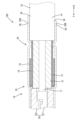
- FIG. 2 is a side sectional view of the shield conductive path of the first embodiment.
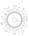
- FIG. 3 is a sectional view taken along line AA in FIG.
- FIG. 4 is a partially exploded view of the outer conductor of Embodiment 1.
- FIG. 5 is a partially exploded view of the outer conductor of the second embodiment.
- FIG. 6 is a partial side view of the shield conductive path of the second embodiment.
- FIG. 7 is a cross-sectional view taken along line BB in FIG.
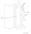
- FIG. 8 is a partially exploded view of the outer conductor of another embodiment.
- the crimping structure between the electric wire and the outer conductor of the present disclosure is as follows: (1) An open barrel-shaped crimping part is provided on the outer conductor connected to the end of the electric wire and is crimped to the outer periphery of the electric wire.
- the crimp portion includes a substrate portion, a plurality of extension portions, and a plurality of claw portions.
- the substrate portion is arranged to surround the outer periphery of the electric wire.
- the plurality of extending portions extend in a cantilevered manner backward in the axial direction of the electric wire from the rear edge of the substrate portion, and are arranged in line in the circumferential direction of the electric wire.
- the plurality of claw portions are formed by bending the rear end portion of each extension portion inward in the radial direction of the electric wire, and bite into the outer surface of the electric wire. Between circumferentially adjacent claws, side edges of the claws that extend along the radial direction and are opposed to each other are offset in the axial direction. According to this configuration, since the side edges of the circumferentially opposing claws are offset in the axial direction between the circumferentially adjacent claws, the protruding ends of the claws do not need to be made thinner. Also, interference between adjacent claw parts can be avoided. This allows the tips of the wide claws to bite into the outer surface of the electric wire, thereby firmly fixing the outer conductor and the electric wire.
- the claw portion is bent along a circumferential crease, and the creases of circumferentially adjacent extending portions are disposed offset in the axial direction. According to this configuration, by simply shifting the folds of adjacent extensions in the axial direction, it is possible to avoid interference between adjacent claws, thereby making the tip of each claw narrower. It can be inserted into the outer surface of the wire without causing any damage.
- the rear edge of the base plate is formed with a through hole that penetrates in the radial direction, and the area of the rear edge of the base where the through hole is formed extends rearward.
- the extending portion includes a first extending portion and a second extending portion that are adjacent to each other in the circumferential direction. In the axial direction, the dimensions of the first extension are larger than the dimensions of the second extension.
- the first extension part is arranged in an area of the rear edge of the substrate part where the through hole is formed, and the second extension part is arranged in an area of the rear edge of the substrate part where the through hole is not formed.
- the position where the first extension part having a large dimension in the axial direction extends from the rear edge of the base plate is rearward of the position from which the second extension part having a small dimension in the axial direction extends. Therefore, it is possible to prevent the claw portion of the first extension portion and the claw portion of the second extension portion from interfering with each other.
- the claw portion is bent along a fold diagonally with respect to both the axial direction and the circumferential direction, and the positions of the folds adjacent to each other in the circumferential direction are aligned in the axial direction. It is preferable. According to this configuration, since the positions of the circumferentially adjacent folds are aligned in the axial direction, it is possible to avoid interference between adjacent claw portions, and it is possible to improve the appearance.
- the shielded conductive path 100 includes a shielded wire 10, a sleeve 18 fitted around the shielded wire 10, which is an electric wire, and a shielded terminal 20 connected to the front end of the shielded wire 10.
- An outer conductor 16 is connected to the tip of the shielded wire 10.
- the shielded wire 10 is arranged with its axial direction facing the front-rear direction.
- the shielded electric wire 10 has a configuration in which a core wire 11 is surrounded by an insulating coating 12, a cylindrical shield layer 13 is placed on the outer periphery of the insulating coating 12, and the outer periphery of the shield layer 13 is surrounded by a sheath 14.
- the shield layer 13 is composed of a braided wire. As shown in FIG. 2, at the front end of the shielded wire 10, the sheath 14 and the insulation coating 12 are removed, and the core wire 11 is exposed to the front of the insulation coating 12. Behind the exposed core wire 11, the sheath 14 is removed and the shield layer 13 is exposed.
- a sleeve 18 is fitted onto the outer peripheral surface of the shield layer 13 exposed after the sheath 14 is removed.
- the sleeve 18 has a cylindrical shape.
- Sleeve 18 surrounds shield layer 13 and insulation coating 12.
- the front end of the shield layer 13 is folded back to cover the outer periphery of the sleeve 18.
- a region of the shield layer 13 that surrounds the sleeve 18 is defined as a folded portion 15 .
- the front end of the sleeve 18 is located slightly rearward than the front end of the insulation sheath 12.
- the rear end of the sleeve 18 is located forward of the front end of the sheath 14.
- the front end of the sheath 14 and the rear end of the sleeve 18 are spaced apart from each other in the axial direction.
- the shield terminal 20 includes an inner conductor 21 connected to the front end of the core wire 11 and a dielectric body 22 that accommodates the inner conductor 21.
- the inner conductor 21 is crimped to the front end of the core wire 11.
- the inner conductor 21 and the dielectric 22 are housed in an outer conductor 16, which will be described later.
- the outer conductor 16 includes a crimp portion 25.
- the crimping portion 25 is a portion for fixing the outer conductor 16 to the outer circumferential surface of the shielded electric wire 10 by being crimped to the outer circumference of the shielded electric wire 10 .
- the front end of the shielded wire 10 and the rear end of the shielded terminal 20 are connected in a state where they are restricted from coming apart in the axial direction, and the outer conductor is 16 and the shield layer 13 are electrically connected.
- a retaining portion 29 extending in the circumferential direction of the shielded wire 10 is formed in the crimp portion 25 (see FIG.
- the retaining portion 29 has a shape in which a portion of the crimp portion 25 is pushed out radially inward. In the state in which the crimp portion 25 is crimped to the shielded wire 10, the retaining portion 29 is continuous throughout the circumferential direction.
- the crimp portion 25 includes a base plate portion 26, a plurality of extension portions 28, and a plurality of claw portions 30.
- the base plate portion 26 is provided at the rear of the retaining portion 29 (see FIG. 1).
- the substrate portion 26 has a so-called open barrel shape in which a portion of the circumferential direction is cut out along the axial direction.
- the cutout portion of the substrate portion 26 is closed to form an annular shape, and the substrate portion 26 is arranged to surround the outer periphery of the shielded wire 10.
- the substrate portion 26 is provided with an outer circumferential locking portion 33 and an inner circumferential locking portion 37 .
- the outer peripheral locking portion 33 extends in one direction in the circumferential direction so as to straddle the cut-out portion of the base plate portion 26 (see FIG. 1).
- the outer circumferential locking portion 33 has a base portion 34 that extends flush from the base plate portion 26, and a locking protrusion 35 that is folded back inward in the radial direction from the protruding end of the base portion 34.
- the locking protrusion 35 is arranged so as to overlap the inner surface of the base 34 and is located radially inner than the base 34 .
- the locking protrusion 35 protrudes radially inward from the base plate portion 26.
- the locking protrusion 35 has a first locking surface 36 facing opposite to the protruding direction of the base 34 in the circumferential direction.
- the inner circumferential locking portion 37 extends in the opposite direction to the outer circumferential locking portion 33, that is, in the other direction in the circumferential direction (see FIG. 1).
- a rectangular through hole 38 that penetrates in the plate thickness direction (radial direction) is formed in the rear edge portion of the base plate portion 26 so as to be lined up in the circumferential direction with respect to the inner peripheral side locking portion 37 (Fig. 1 reference).
- the inner peripheral surfaces along the opening edge of the through hole 38 the inner surface on the side that is parallel to the axial direction and closer to the inner peripheral locking part 37 in the circumferential direction is the first locking part of the locking protrusion 35.
- the surfaces 36 function as second locking surfaces 39 that are locked oppositely.
- a region of the rear edge of the substrate portion 26 where the inner circumferential locking portion 37 and the through hole 38 are formed projects further rearward than a portion where the inner circumferential locking portion 37 and the through hole 38 are not formed. (See Figure 4).
- the plurality of extension parts 28 are shaped like cantilevers extending rearward in the axial direction from the rear edge of the base plate part 26.
- the extending portion 28 includes a first extending portion 28A and a second extending portion 28B. In the axial direction, the dimensions of the first extending portion 28A are larger than the dimensions of the second extending portion 28B.
- the first extending portion 28A and the second extending portion 28B (a plurality of extending portions 28) are arranged adjacent to each other in the circumferential direction and alternately lined up (in FIG. 4, the circumferential direction corresponds to the vertical direction). ).
- the second extending portion 28B is arranged at the rear edge of the base plate 26 where the base end of the outer locking portion 33 is located, and the base end of the inner locking portion 37 is located at the rear edge of the base plate 26.
- a first extending portion 28A is arranged at the rear end edge of the substrate portion 26 located therein. On the rear edge of the substrate portion 26, in the region where the through hole 38 is formed, the first extending portion 28A is disposed, and the second extending portion 28B is not disposed.
- a first extending portion 28A and a second extending portion 28B are arranged in a region of the rear edge of the substrate portion 26 where the inner circumferential locking portion 37 and the through hole 38 are not formed.
- the extending portions 28 are arranged so as to be biased toward two locations, one on the outer circumferential side locking portion 33 side and the other on the inner circumferential side locking portion 37 side.
- the extending portion 28 is arranged in two parts: on the outer circumferential locking portion 33 side and on the inner circumferential locking portion 37 side.
- a section 28C is arranged.
- one first extending portion 28A is sandwiched between two second extending portions 28B in the circumferential direction.
- the other side extending portion 28D is arranged, which is constituted by one second extending portion 28B and two first extending portions 28A. has been done.
- one second extending portion 28B is sandwiched between two first extending portions 28A in the circumferential direction. That is, the first extending portions 28A and the second extending portions 28B are arranged alternately adjacent to each other in the circumferential direction.
- the dimension between the circumferentially adjacent extension parts 28 is the same as the width direction (circumferential direction) dimension of each extension part 28.
- the dimension between the one side extension part 28C and the other side extension part 28D in the circumferential direction is the dimension between the circumferentially adjacent extension parts 28 in the one side extension part 28C and the other side extension part 28D. larger than the dimensions.
- a carrier is connected to the rear end edge of the base plate section 26 between the one side extension part 28C and the other side extension part 28D.
- the plurality of claw portions 30 are provided by bending the rear end portion of each extension portion 28 inward in the radial direction (see FIGS. 1 and 2). Specifically, each claw portion 30 is bent along a crease F1 extending in the circumferential direction. Both ends of each claw portion 30 in the circumferential direction are parallel to each other and extend along the radial direction (see FIG. 3). The leading edge (rear end edge) of each claw portion 30 is formed parallel to the fold line F1. That is, the tip edge (rear edge) of each claw portion 30 extends in the circumferential direction. At the tip of each claw portion 30, both ends in the circumferential direction are chamfered (C-face).
- each claw portion 30 in the radial direction The dimensions (projection dimensions) of each claw portion 30 in the radial direction are the same. In other words, each claw portion 30 projects radially inward from the inner surface of each extension portion 28 with the same dimensions (see FIG. 3).
- the folds F1 of the extending portions 28 that are adjacent to each other in the circumferential direction are arranged to be shifted in the axial direction (see FIG. 4). These claws 30 bite into the outer surface of the sheath 14 of the shielded wire 10 by crimping the crimp portion 25 onto the shielded wire 10 (see FIGS. 2 and 3). This suppresses the outer conductor 16 from moving in the axial direction or rotating in the circumferential direction with respect to the shielded wire 10. Between the circumferentially adjacent claws 30, the side edges of the claws 30 that extend along the radial direction and face each other are offset in the axial direction (see FIG. 1).
- the crimping part 25 and the front end of the shielded wire 10 are set in an applicator (not shown).
- the substrate portion 26 is deformed to reduce its diameter and is crimped so as to wrap around the outer periphery of the shielded wire 10 .
- the crimping part 25 is crimped to the shielded wire 10
- the area of the crimping part 25 in front of the retaining part 29 is crimped to the outer peripheral surfaces of the sleeve 18 and the folded part 15
- the folded part 15 is crimped to the sleeve 18 . 25 in the radial direction (see FIG. 2).
- the folded portion 15, the sleeve 18, and the crimp portion 25 are fixed in an integrated state so as to be electrically conductive.
- the retaining part 29 is disposed between the front end of the sheath 14 and the rear end of the sleeve 18 (see FIG. 2). Then, the outer peripheral side locking portion 33 straddles the cut-out portion of the base plate portion 26, and the locking protrusion 35 is accommodated in the through hole 38 (see FIG. 3).
- the inner circumferential locking portion 37 with which the inner surface of the base 34 comes into contact is pressed radially inward via the base 34 .
- the inner circumferential locking portion 37 with which the inner surface of the base portion 34 comes into contact is deformed so as to be recessed radially inward (see FIG.
- first locking surface 36 and the second locking surface 39 are in a state where they face each other in the circumferential direction, and are brought into contact and locked (see FIGS. 1 and 3). Due to the locking between the first locking surface 36 and the second locking surface 39, the crimp portion 25 is prevented from opening in the circumferential direction and is maintained fixed to the outer periphery of the shielded wire 10.
- each claw part 30 When crimping the crimping part 25 to the shielded wire 10, each claw part 30 is pressed radially inward and bites into the outer surface of the sheath 14 while narrowing the interval between the circumferentially adjacent claw parts 30. .
- the claw portions 30 adjacent to each other in the circumferential direction are arranged offset in the axial direction. For this reason, each claw part 30 does not contact in the circumferential direction even if the interval between the claw parts 30 adjacent to each other in the circumferential direction narrows.
- the crimping structure of the electric wire and the outer conductor of the present disclosure includes an open barrel-shaped crimping part 25 that is provided on the outer conductor 16 connected to the end of the shielded electric wire 10 and is crimped to the outer periphery of the shielded electric wire 10.
- the crimp section 25 includes a substrate section 26, a plurality of extension sections 28, and a plurality of claw sections 30.
- the substrate portion 26 is arranged to surround the outer periphery of the shielded wire 10.
- the plurality of extension portions 28 are arranged in a cantilever shape extending backward in the axial direction of the shielded wire 10 from the rear edge of the substrate portion 26 in the circumferential direction of the shielded wire 10 .
- the plurality of claw portions 30 are formed by bending the rear end portion of each extension portion 28 inward in the radial direction of the shielded wire 10, and bite into the outer surface of the sheath 14 of the shielded wire 10. Between the circumferentially adjacent claws 30, the side edges of the claws 30 that extend along the radial direction and are opposed to each other are offset in the axial direction. According to this configuration, since the side edges of the circumferentially opposing claws 30 are shifted in the axial direction between the circumferentially adjacent claws 30, the protruding ends of the claws 30 are narrowed. Even if it is not done, interference between adjacent claw parts 30 can be avoided. This allows the tips of the wide claw portions 30 to bite into the outer surface of the shielded wire 10, so that the outer conductor 16 and the shielded wire 10 can be firmly fixed.
- the claw portion 30 is bent along a circumferential fold line F1, and the fold lines F1 of circumferentially adjacent extension portions 28 are arranged to be shifted in the axial direction. According to this configuration, by simply shifting the fold line F1 of the adjacent extending portions 28 in the axial direction, it is possible to prevent the adjacent claw portions 30 from interfering with each other.
- the tip can be made to bite into the outer surface of the shielded wire 10 without being made thinner.
- a through hole 38 that penetrates in the radial direction is formed in the rear edge of the base plate part 26, and a region of the rear edge of the base plate part 26 where the through hole 38 is formed projects rearward.
- the extending portion 28 includes a first extending portion 28A and a second extending portion 28B that are adjacent to each other in the circumferential direction. In the axial direction, the dimensions of the first extending portion 28A are larger than the dimensions of the second extending portion 28B.
- a first extending portion 28A is arranged in a region of the rear edge of the substrate portion 26 where the through hole 38 is formed, and a second extending portion 28A is arranged in a region of the rear edge of the substrate portion 26 where the through hole 38 is not formed.
- An extending portion 28B is arranged.
- the position where the first extension part 28A having a large dimension in the axial direction extends from the rear edge of the base plate part 26 is the position from which the second extension part 28B having a small dimension in the axial direction extends. It is set further back than the This can prevent the claw portions 30 of the first extension portion 28A and the claw portion 30 of the second extension portion 28B from interfering with each other.
- FIGS. 5 to 7 A second embodiment embodying the present disclosure will be described with reference to FIGS. 5 to 7.
- the shield conductive path 200 having the crimping structure of the electric wire and the outer conductor of the second embodiment differs from the first embodiment in the direction in which the fold line F2 extends. Since the other configurations are the same as those of the first embodiment, the same configurations are denoted by the same reference numerals, and explanations of the structure, operation, and effect will be omitted.
- "front side” and “back side” are respectively represented by "F” and "B".
- each claw portion 130 is formed parallel to the fold line F2.
- Each claw portion 130 is bent along a fold line F2 that is diagonal to both the axial direction and the circumferential direction (see FIG. 6). As shown in FIG. 7, when viewed from the axial direction, the tip edge of each claw portion 130 extends in the circumferential direction.
- the claw portion 130 is bent along a fold line F2 that is diagonal to both the axial direction and the circumferential direction, and the positions of the fold lines F2 adjacent to each other in the circumferential direction are aligned in the axial direction. According to this configuration, since the positions of the folds F2 adjacent to each other in the circumferential direction are aligned in the axial direction, it is possible to avoid interference between the adjacent claw portions 130 and to improve the appearance.
- the extending portion 228, which has a large axial dimension, can be made difficult to bend in the radial direction, and the state in which the claw portion 230 bites into the sheath can be easily maintained.
- the adhesion between the outer conductor and the shielded wire is strengthened. can do.
- the shield layer may be a metal foil.
Landscapes
- Connections Effected By Soldering, Adhesion, Or Permanent Deformation (AREA)
- Details Of Connecting Devices For Male And Female Coupling (AREA)
Abstract
Description
電線の端部に接続される外導体に設けられ、前記電線の外周に圧着されるオープンバレル状の圧着部を備え、
前記圧着部は、
前記電線の外周を包囲するように配置された基板部と、
前記基板部の後縁から前記電線の軸線方向の後向きに片持ち状に延出した形態で、前記電線の周方向に複数並んで配置された延出部と、
各前記延出部の後端部を前記電線の径方向内向きに屈曲して形成され、前記電線の外面に食い込む複数の爪部と、
を有し、
前記周方向に隣合う前記爪部の相互間においては、前記径方向に沿って延び、且つ互いに対向する前記爪部の側縁同士が、前記軸線方向にずれている。
最初に本開示の実施形態を列記して説明する。
本開示の電線と外導体との圧着構造は、
(1)電線の端部に接続される外導体に設けられ、電線の外周に圧着されるオープンバレル状の圧着部を備えている。圧着部は、基板部と、複数の延出部と、複数の爪部と、を有している。基板部は、電線の外周を包囲するように配置される。複数の延出部は、基板部の後縁から電線の軸線方向の後向きに片持ち状に延出した形態で、電線の周方向に並んで配置される。複数の爪部は、各延出部の後端部を電線の径方向内向きに屈曲して形成され、電線の外面に食い込む。周方向に隣合う爪部の相互間においては、径方向に沿って延び、且つ互いに対向する爪部の側縁同士が、軸線方向にずれている。この構成によれば、周方向に隣合う爪部の相互間においては、周方向に対向する爪部の側縁が軸線方向にずれているので、爪部の突出端部を細らせなくても、隣合う爪部同士が干渉することを避けることができる。これによって、幅広の爪部の先端を電線の外面に食い込ませることができるので、外導体と電線とを強固に固着することができる。
[実施形態1]
本開示を具体化した実施形態1を、図1から図4を参照して説明する。図中、「前側」、「後側」は、それぞれ「F」、及び「B」で表される。
本開示を具体化した実施形態2を、図5から図7を参照して説明する。実施形態2の電線と外導体との圧着構造を有するシールド導電路200は、折り目F2が延びる向きが、実施形態1と異なる。その他の構成については実施形態1と同じであるため、同じ構成については、同一符号を付し、構造、作用及び効果の説明は省略する。図中、「前側」、「後側」は、それぞれ「F」、及び「B」で表される。
本開示は、上記記述及び図面によって説明した実施形態に限定されるものではなく、請求の範囲によって示される。本発明には、請求の範囲と均等の意味及び請求の範囲内でのすべての変更が含まれ、下記のような実施形態も含まれることが意図される。
(1)実施形態1、2とは異なり、図8に示すように、軸線方向の寸法を3種類に異ならせた延出部228を設けてもよい。この場合、軸線方向の寸法が大きい延出部228の周方向の幅寸法を、軸線方向の寸法が小さい延出部228よりも大きくすることが好ましい。これによって、軸線方向の寸法が大きい延出部228を径方向に撓み難くすることができ、爪部230がシースに食い込んだ状態を保持し易くできる。
(2)爪部の先端における周方向の幅寸法を大きくする(すなわち、シースの外面に接触する爪部先端の接触寸法を大きくする)ことによって、外導体とシールド電線との固着をより強固にすることができる。このため、実施形態1、2とは異なり、図8に示すように、基板部226の後縁の全体にわたり延出部228を設けると、シースの外面に接触する爪部先端の接触寸法をより大きくすることができ、外導体とシールド電線との固着をより強固にすることができる。
(3)実施形態1、2とは異なり、シールド層を金属箔としてもよい。
11…芯線
12…絶縁被覆
13…シールド層
14…シース
15…折返部
16…外導体
18…スリーブ
20…シールド端子
21…内導体
22…誘電体
25…圧着部
26,226…基板部
28,128,228…延出部
28A…第1延出部
28B…第2延出部
28C…一方側延出部
28D…他方側延出部
29…抜止部
30,130,230…爪部
33…外周側係止部
34…基部
35…係止突部
36…第1係止面
37…内周側係止部
38…貫通孔
39…第2係止面
100,200…シールド導電路
F1,F2…折り目
Claims (4)
- 電線の端部に接続される外導体に設けられ、前記電線の外周に圧着されるオープンバレル状の圧着部を備え、
前記圧着部は、
前記電線の外周を包囲するように配置された基板部と、
前記基板部の後縁から前記電線の軸線方向の後向きに片持ち状に延出した形態で、前記電線の周方向に複数並んで配置された延出部と、
各前記延出部の後端部を前記電線の径方向内向きに屈曲して形成され、前記電線の外面に食い込む複数の爪部と、
を有し、
前記周方向に隣合う前記爪部の相互間においては、前記径方向に沿って延び、且つ互いに対向する前記爪部の側縁同士が、前記軸線方向にずれている、電線と外導体との圧着構造。 - 前記爪部は、前記周方向の折り目に沿って屈曲されており、
前記周方向に隣合う前記延出部の前記折り目が、前記軸線方向にずれて配置されている請求項1に記載の電線と外導体との圧着構造。 - 前記基板部の後縁部には、前記径方向に貫通した貫通孔が形成されており、
前記基板部の後縁のうち前記貫通孔が形成されている領域は、後方へ張り出しており、
前記延出部は、前記周方向に隣合う第1延出部と第2延出部と、を有し、
前記軸線方向において、前記第1延出部の寸法は、前記第2延出部の寸法よりも大きく、
前記基板部の後縁のうち前記貫通孔が形成されている領域に、前記第1延出部が配置され、
前記基板部の後縁のうち前記貫通孔が形成されていない領域に、前記第2延出部が配置されている、請求項2に記載の電線と外導体との圧着構造。 - 前記爪部は、前記軸線方向及び前記周方向の両方向に対して斜め方向の折り目に沿って屈曲されており、
前記周方向に隣合う前記折り目の位置が、前記軸線方向において揃っている請求項1に記載の電線と外導体との圧着構造。
Priority Applications (2)
| Application Number | Priority Date | Filing Date | Title |
|---|---|---|---|
| CN202380035388.6A CN119054163A (zh) | 2022-05-09 | 2023-04-18 | 电线和外导体的压接结构 |
| US18/862,551 US20250350041A1 (en) | 2022-05-09 | 2023-04-18 | Structure for crimping wire and outer conductor |
Applications Claiming Priority (2)
| Application Number | Priority Date | Filing Date | Title |
|---|---|---|---|
| JP2022-077041 | 2022-05-09 | ||
| JP2022077041A JP7679796B2 (ja) | 2022-05-09 | 2022-05-09 | 電線と外導体との圧着構造 |
Publications (1)
| Publication Number | Publication Date |
|---|---|
| WO2023218871A1 true WO2023218871A1 (ja) | 2023-11-16 |
Family
ID=88730262
Family Applications (1)
| Application Number | Title | Priority Date | Filing Date |
|---|---|---|---|
| PCT/JP2023/015407 Ceased WO2023218871A1 (ja) | 2022-05-09 | 2023-04-18 | 電線と外導体との圧着構造 |
Country Status (4)
| Country | Link |
|---|---|
| US (1) | US20250350041A1 (ja) |
| JP (1) | JP7679796B2 (ja) |
| CN (1) | CN119054163A (ja) |
| WO (1) | WO2023218871A1 (ja) |
Families Citing this family (1)
| Publication number | Priority date | Publication date | Assignee | Title |
|---|---|---|---|---|
| DE102024114406B4 (de) * | 2024-05-23 | 2026-01-29 | Amphenol-Tuchel Electronics Gmbh | Verbindungsanordnung mit Schirmrohr |
Citations (3)
| Publication number | Priority date | Publication date | Assignee | Title |
|---|---|---|---|---|
| JP2019029204A (ja) * | 2017-07-31 | 2019-02-21 | 株式会社オートネットワーク技術研究所 | 電線の圧着構造及びシールド導電路 |
| JP2021180115A (ja) * | 2020-05-14 | 2021-11-18 | 株式会社オートネットワーク技術研究所 | シールド導電路 |
| WO2023282225A1 (ja) * | 2021-07-07 | 2023-01-12 | 株式会社オートネットワーク技術研究所 | シールド導電路 |
-
2022
- 2022-05-09 JP JP2022077041A patent/JP7679796B2/ja active Active
-
2023
- 2023-04-18 WO PCT/JP2023/015407 patent/WO2023218871A1/ja not_active Ceased
- 2023-04-18 CN CN202380035388.6A patent/CN119054163A/zh active Pending
- 2023-04-18 US US18/862,551 patent/US20250350041A1/en active Pending
Patent Citations (3)
| Publication number | Priority date | Publication date | Assignee | Title |
|---|---|---|---|---|
| JP2019029204A (ja) * | 2017-07-31 | 2019-02-21 | 株式会社オートネットワーク技術研究所 | 電線の圧着構造及びシールド導電路 |
| JP2021180115A (ja) * | 2020-05-14 | 2021-11-18 | 株式会社オートネットワーク技術研究所 | シールド導電路 |
| WO2023282225A1 (ja) * | 2021-07-07 | 2023-01-12 | 株式会社オートネットワーク技術研究所 | シールド導電路 |
Also Published As
| Publication number | Publication date |
|---|---|
| US20250350041A1 (en) | 2025-11-13 |
| JP7679796B2 (ja) | 2025-05-20 |
| JP2023166175A (ja) | 2023-11-21 |
| CN119054163A (zh) | 2024-11-29 |
Similar Documents
| Publication | Publication Date | Title |
|---|---|---|
| JP7096123B2 (ja) | シールド電線の端子接続構造 | |
| WO2021029201A1 (ja) | ケーブル付きコネクタ | |
| JP7792070B2 (ja) | シールド導電路 | |
| JP7129010B2 (ja) | コネクタ構造体 | |
| JP7380420B2 (ja) | シールド導電路 | |
| WO2023282225A1 (ja) | シールド導電路 | |
| WO2023218871A1 (ja) | 電線と外導体との圧着構造 | |
| JP7406711B2 (ja) | シールド導電路 | |
| EP4434120A1 (en) | High deformation and retention ferrule | |
| JPH10144405A (ja) | シールドコネクタ | |
| JPH1140274A (ja) | シールドコネクタ | |
| US20250246851A1 (en) | Shielded electrically conductive path | |
| JP4392381B2 (ja) | シールドコネクタ | |
| JP3375280B2 (ja) | シールドコネクタ | |
| US20250350071A1 (en) | Wire-and-outer conductor crimping structure | |
| JP2021180089A (ja) | コネクタ装置 | |
| JPH1140273A (ja) | シールドコネクタ | |
| US20250167493A1 (en) | Shield connector | |
| JP5344899B2 (ja) | 同軸ケーブル用コネクタ | |
| JP2025162254A (ja) | 高周波コネクタ及びケーブル付き高周波コネクタ | |
| JPH11233202A (ja) | コネクタ | |
| JP2026032657A (ja) | 端子モジュール | |
| WO2024018868A1 (ja) | シールド受け部材およびシールドコネクタ | |
| WO2023149184A1 (ja) | コネクタ | |
| JP2026022785A (ja) | シールドコネクタ |
Legal Events
| Date | Code | Title | Description |
|---|---|---|---|
| 121 | Ep: the epo has been informed by wipo that ep was designated in this application |
Ref document number: 23803353 Country of ref document: EP Kind code of ref document: A1 |
|
| WWE | Wipo information: entry into national phase |
Ref document number: 202380035388.6 Country of ref document: CN |
|
| WWE | Wipo information: entry into national phase |
Ref document number: 18862551 Country of ref document: US |
|
| NENP | Non-entry into the national phase |
Ref country code: DE |
|
| 122 | Ep: pct application non-entry in european phase |
Ref document number: 23803353 Country of ref document: EP Kind code of ref document: A1 |
|
| WWP | Wipo information: published in national office |
Ref document number: 18862551 Country of ref document: US |