WO2023218770A1 - 表示制御装置 - Google Patents
表示制御装置 Download PDFInfo
- Publication number
- WO2023218770A1 WO2023218770A1 PCT/JP2023/011806 JP2023011806W WO2023218770A1 WO 2023218770 A1 WO2023218770 A1 WO 2023218770A1 JP 2023011806 W JP2023011806 W JP 2023011806W WO 2023218770 A1 WO2023218770 A1 WO 2023218770A1
- Authority
- WO
- WIPO (PCT)
- Prior art keywords
- display
- target
- display target
- frame
- control unit
- Prior art date
- Legal status (The legal status is an assumption and is not a legal conclusion. Google has not performed a legal analysis and makes no representation as to the accuracy of the status listed.)
- Ceased
Links
Images


Classifications
-
- G—PHYSICS
- G06—COMPUTING OR CALCULATING; COUNTING
- G06T—IMAGE DATA PROCESSING OR GENERATION, IN GENERAL
- G06T19/00—Manipulating three-dimensional [3D] models or images for computer graphics
-
- G—PHYSICS
- G09—EDUCATION; CRYPTOGRAPHY; DISPLAY; ADVERTISING; SEALS
- G09G—ARRANGEMENTS OR CIRCUITS FOR CONTROL OF INDICATING DEVICES USING STATIC MEANS TO PRESENT VARIABLE INFORMATION
- G09G5/00—Control arrangements or circuits for visual indicators common to cathode-ray tube indicators and other visual indicators
- G09G5/36—Control arrangements or circuits for visual indicators common to cathode-ray tube indicators and other visual indicators characterised by the display of a graphic pattern, e.g. using an all-points-addressable [APA] memory
- G09G5/37—Details of the operation on graphic patterns
- G09G5/373—Details of the operation on graphic patterns for modifying the size of the graphic pattern
-
- G—PHYSICS
- G09—EDUCATION; CRYPTOGRAPHY; DISPLAY; ADVERTISING; SEALS
- G09G—ARRANGEMENTS OR CIRCUITS FOR CONTROL OF INDICATING DEVICES USING STATIC MEANS TO PRESENT VARIABLE INFORMATION
- G09G5/00—Control arrangements or circuits for visual indicators common to cathode-ray tube indicators and other visual indicators
- G09G5/36—Control arrangements or circuits for visual indicators common to cathode-ray tube indicators and other visual indicators characterised by the display of a graphic pattern, e.g. using an all-points-addressable [APA] memory
- G09G5/38—Control arrangements or circuits for visual indicators common to cathode-ray tube indicators and other visual indicators characterised by the display of a graphic pattern, e.g. using an all-points-addressable [APA] memory with means for controlling the display position
Definitions
- the present invention relates to a display control device.
- Patent Document 1 discloses a technique for setting a display range in a virtual space based on a combination of a viewing angle of an HMD (Head Mounted Display) and a user.
- the HMD displays a display target located within a display range in virtual space.
- the HMD user can visually recognize the display target in the virtual space along with the objects in the real world.
- the reference object is an object in the real world or a virtual object in virtual space.
- a comment on a real-world object when used as a display target, it is more important that the comment on the real-world object be visible in its entirety than on consistency in size with the real-world object.
- display objects for which it is more important to be able to see the entire object than to match it in size with a reference object are not limited to comments on objects in the real world.
- a display object for which it is more important to be able to see the entire display object than consistency in size with the reference object can also be said to be a display object whose relative size to the reference object can be adjusted.
- An object of the present invention is to provide a display control device that can reduce the display of a display object on a display device in a partially missing state where it is more important to see the entire display object than to match the size with a reference object. That's true.
- a display control device includes an acquisition unit that acquires display target information indicating a display target whose size relative to a reference object can be adjusted and a scheduled display position of the display target, and a viewing angle of the display device. and a display control unit that causes the display device to display the entire display target by at least executing a process of controlling a display magnification of the display target based on the display target and the scheduled display position.
- a display object for which it is more important to be able to see the entire display object than to match it in size with a reference object, is displayed on the display device in a partially missing state.
- FIG. 1 is a diagram schematically showing a display control system 1.
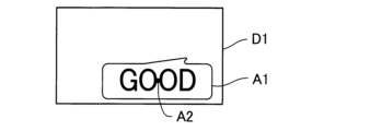
- FIG. It is a figure which shows an example of the display image C1. It is a figure showing an example of display frame D1.
- 3 is a diagram showing the relationship between the viewing angle of the display device 10, the display frame D1, and the display area D2.
- FIG. It is a figure which shows an example of the display area D2 set in the display frame D1.
- 1 is a diagram showing an example of a display device 10.
- FIG. 2 is a diagram showing an example of a terminal device 20.
- FIG. It is a figure which shows the positional relationship of the gravity center part G1 of display object A1, and display planned position A2.
- FIG. 6 is a diagram illustrating an example in which at least a part of the display target A1 does not belong to the display area D2, but a scheduled display position A2 belongs to the display area D2.
- FIG. 6 is a diagram illustrating an example in which at least a part of the display target A1 does not belong to the display area D2 and a scheduled display position A2 does not belong to the display area D2.
- FIG. 12 is a diagram illustrating an example in which the entire display target A1 belongs to the display area D2 at the stage when the display frame generation unit 262a generates the display frame D1.
- 3 is a diagram for explaining the operation of the terminal device 20.
- FIG. 1 is a diagram schematically showing a display control system 1. As shown in FIG.
- the display control system 1 includes a display device 10, a terminal device 20, and a server 30.
- the display device 10 and the terminal device 20 can communicate with each other.
- the terminal device 20 and the server 30 can communicate with each other via the communication network NW.
- the display device 10 is, for example, smart glasses. Smart glasses are eyeglass-shaped display devices.
- the smart glasses are, for example, AR (Augmented Reality) glasses or MR (Mixed Reality) glasses. Smart glasses are also called XR (X Reality) glasses or HMD.
- the display device 10 is not limited to smart glasses, and may be a non-glass-type display device, for example.
- a display device that is not a glasses type is, for example, a goggle-shaped HMD.
- the display device 10 may be included in the terminal device 20.
- the display device 10 is used by the user U.
- Display device 10 includes a display surface 11 .
- the display surface 11 is a transmissive display surface.
- the display surface 11 transmits external light representing the real world while displaying the display object A1. Therefore, the display device 10 can allow the user U to view the real world while allowing the user U to view the display target A1. That is, the display device 10 can provide the user U with augmented reality. Note that when the display target A1 exists in the virtual space, the display device 10 can provide mixed reality to the user U.
- the display surface 11 transmits external light representing a mountain M1 existing in the real world. Therefore, the user U can visually recognize the mountain M1 that exists in the real world and the display target A1 that overlaps the mountain M1. Note that the display target A1 does not have to overlap the mountain M1.
- the display surface 11 is a transmissive display surface
- the display device 10 is an example of a transmissive display device.
- the display target A1 is, for example, a speech bubble.
- the speech bubble shown in FIG. 1 indicates "GOOD" which is a comment regarding the mountain M1.
- the comment regarding mountain M1 is not limited to "GOOD” and can be changed as appropriate.
- Mountain M1 is an example of an object that exists in the real world.
- the object that exists in the real world is not limited to the mountain M1, but may be, for example, a store that exists in the real world.
- An object that exists in the real world is an example of a reference object.
- the size of the display target A1 relative to the reference object can be adjusted. That is, the display object A1 is a display object for which it is more important to be able to see the entire display object than to be consistent in size with the reference object.
- a speech bubble which is an example of the display target A1
- the virtual object is an example of the display target A1.
- the display target A1 and the virtual object are not limited to speech balloons, but may be advertisements or annotations of objects existing in the real world.
- the display surface 11 is not limited to a transmissive display surface, but may be a non-transmissive display surface.
- the display surface 11 displays a virtual object existing in the virtual space in addition to the display target A1.
- the virtual object that exists in the virtual space is, for example, a virtual store that exists in the virtual space.
- the virtual object that exists in the virtual space is not limited to a virtual store that exists in the virtual space, but may be, for example, a virtual pet that exists in the virtual space.
- the display target A1 may be a speech bubble that shows the cry of the virtual pet.
- a speech bubble indicating the cry of a virtual pet is another example of a virtual object.
- a virtual object existing in virtual space is another example of a reference object.
- the display device 10 has a field of view that is determined depending on the model of the display device 10.
- the viewing angle of the display device 10 means the angle of view of the display device 10.
- the viewing angle of the display device 10 may differ depending on the model of the display device 10.
- the terminal device 20 is, for example, a smartphone.
- the terminal device 20 is not limited to a smartphone, and may be, for example, a tablet terminal, a personal computer, or a game device.
- the terminal device 20 is used by a user U, for example.
- the terminal device 20 controls the display device 10.
- the terminal device 20 controls the display of the display target A1 on the display device 10.
- the terminal device 20 acquires display target information B1 from the server 30.
- the display target information B1 is information indicating the display target A1 and the scheduled display position A2 of the display target A1.
- the display target information B1 may further indicate the size of the display target A1.
- the terminal device 20 generates display image information B2 by using display target information B1.
- Display image information B2 is information indicating display image C1.
- FIG. 2 is a diagram showing an example of the display image C1.
- the display image C1 is an image that represents the entire display target A1.
- the terminal device 20 uses the display target information B1 to generate display image information B2, for example, as follows.
- the terminal device 20 generates a display frame D1 based on the display target information B1.
- the display frame D1 is a frame that represents the display target A1 in the first size at the scheduled display position A2.
- the first size may be the size of the display target A1 shown in the display target information B1, or may be a predetermined size.
- FIG. 3 is a diagram showing an example of the display frame D1.
- the display frame D1 is generated using, for example, VRAM (Video Random Access Memory) of the terminal device 20.
- VRAM Video Random Access Memory
- the terminal device 20 sets a display area D2 in the display frame D1 based on the viewing angle of the display device 10. For example, the terminal device 20 sets the display area D2 according to the viewing angle of the display device 10.
- FIG. 4 is a diagram showing the relationship between the viewing angle of the display device 10, the display frame D1, and the display area D2.
- the display target A1 is omitted.
- the point F1 is a reference point for the viewing angle of the display device 10.
- the point F1 is located on the normal line of the display frame D1 passing through the center O of the display frame D1.
- Point F1 is far from center O.
- the distance between point F1 and center O is set in advance.
- the distance between the point F1 and the center O may be specified by viewing angle information E1, which will be described later.
- the viewing angle of the display device 10 includes a horizontal viewing angle ⁇ h of the display device 10 and a vertical viewing angle ⁇ v of the display device 10.
- the horizontal viewing angle ⁇ h of the display device 10 means the horizontal viewing angle of the display device 10.
- the vertical viewing angle ⁇ v of the display device 10 means the vertical viewing angle of the display device 10.
- the size of the display area D2 depends on the viewing angle of the display device 10. For example, the size of the display area D2 increases as the viewing angle of the display device 10 increases. The size of the display area D2 decreases as the viewing angle of the display device 10 decreases.
- FIG. 5 is a diagram showing an example of the display area D2 set in the display frame D1.
- the display area D2 shown in FIG. 5 does not include the bottom A1a of the display target A1. That is, in the example shown in FIG. 5, at least a portion of the display target A1 does not belong to the display area D2.
- the terminal device 20 When at least a part of the display target A1 does not belong to the display area D2, the terminal device 20 at least executes a process of reducing the display magnification of the display target A1 in the display frame D1, so that the entire display target A1 is placed in the display area. Store it in D2.
- the terminal device 20 If the entire display target A1 fits within the display area D2, the terminal device 20 generates a display image C1 representing the display area D2.
- An example of the display image C1 is shown in FIG. 2 described above.
- the terminal device 20 generates information indicating the display image C1 as display image information B2.
- the terminal device 20 causes the display device 10 to display the entire display target A1 by providing the display image information B2 to the display device 10.
- the server 30 transmits display target information B1.
- the server 30 transmits display target information B1 to the terminal device 20.
- FIG. 6 is a diagram showing an example of the display device 10.
- the display device 10 includes a transparent display device 12, a communication device 13, a storage device 14, a processing device 15, and a bus 16.
- the bus 16 is wiring for communicating information.
- the bus 16 interconnects the transparent display device 12, the communication device 13, the storage device 14, and the processing device 15.
- the bus 16 may be configured using a single bus, or may be configured using different buses for each element such as a device.
- the transmissive display device 12 transmits external light representing the real world while displaying the display target A1.
- Transmissive display device 12 includes a display panel and a half mirror.
- the display panel is, for example, a liquid crystal panel or an organic EL (Electro Luminescence) panel.
- the display panel emits light representing the display image C1.
- the half mirror includes a display surface 11.
- the half mirror reflects the light emitted by the display panel toward the user's U eyes.
- the half mirror guides the external light representing the real world to the user's U's eyes by transmitting the external light representing the real world.
- a non-transmissive display device may be used instead of the transmissive display device 12.
- the communication device 13 communicates with the terminal device 20 wirelessly.
- the communication device 13 may communicate with the terminal device 20 by wire.
- the storage device 14 is a recording medium that can be read by the processing device 15.
- Storage device 14 includes one or more memories.
- the storage device 14 includes, for example, nonvolatile memory and volatile memory.
- Nonvolatile memories include, for example, ROM (Read Only Memory), EPROM (Erasable Programmable Read Only Memory), and EEPROM (Electrically Erasable Programmable Read Only Memory).
- Volatile memory is, for example, RAM (Random Access Memory) and VRAM.
- the storage device 14 stores viewing angle information E1 and a program PG1.
- the viewing angle information E1 is information indicating the viewing angle of the display device 10.
- the viewing angle information E1 indicates the horizontal viewing angle ⁇ h of the display device 10 and the vertical viewing angle ⁇ v of the display device 10.
- the processing device 15 includes one or more CPUs (Central Processing Units).
- CPUs Central Processing Units
- One or more CPUs are an example of one or more processors.
- Each of the processor and CPU is an example of a computer.
- the processing device 15 reads the program PG1 from the storage device 14.
- the processing device 15 functions as the operation control section 151 by executing the program PG1.
- the operation control unit 151 may be configured by a circuit such as a DSP (Digital Signal Processor), an ASIC (Application Specific Integrated Circuit), or an FPGA (Field Programmable Gate Array).
- the operation control unit 151 controls the operation of the display device 10. For example, the operation control unit 151 reads the viewing angle information E1 from the storage device 14. The operation control unit 151 causes the communication device 13 to transmit the viewing angle information E1 to the terminal device 20. When the communication device 13 receives the display image information B2 from the terminal device 20, the operation control unit 151 acquires the display image information B2 from the communication device 13. The operation control unit 151 causes the transparent display device 12 to display the display image C1 indicated by the display image information B2.
- FIG. 7 is a diagram showing an example of the terminal device 20.
- the terminal device 20 is an example of a display control device.
- the terminal device 20 includes an input device 21 , a display device 22 , a communication device 23 , a communication device 24 , a storage device 25 , a processing device 26 , and a bus 27 .
- the bus 27 is wiring for communicating information.
- the bus 27 interconnects the input device 21, the display device 22, the communication device 23, the communication device 24, the storage device 25, and the processing device 26.
- the bus 27 may be configured using a single bus, or may be configured using different buses for each element such as a device.
- the input device 21 includes a touch panel.
- the input device 21 may include a plurality of operation keys in addition to a touch panel.
- the input device 21 may include a plurality of operation keys without including a touch panel.
- the input device 21 receives operations performed by the user U.
- the display device 22 includes a display.
- a touch panel of the input device 21 is stacked on the display of the display device 22 .
- the display device 22 displays various information.
- the communication device 23 communicates with the server 30 via the communication network NW.
- the communication device 23 may communicate with the server 30 without going through the communication network NW.
- the communication device 24 communicates with the display device 10 wirelessly.
- the communication device 24 may communicate with the display device 10 by wire.
- the storage device 25 is a recording medium that can be read by the processing device 26.
- Storage device 25 includes one or more memories.
- the storage device 25 includes, for example, nonvolatile memory and volatile memory.
- the storage device 25 stores a program PG2.
- the storage device 25 may further store viewing angle information E1. When the storage device 25 stores the viewing angle information E1, the storage device 14 of the display device 10 does not need to store the viewing angle information E1.
- the processing device 26 includes one or more CPUs.
- the processing device 26 is another example of a display control device.
- the processing device 26 reads the program PG2 from the storage device 25.
- the processing device 26 functions as an acquisition section 261 and a display control section 262 by executing the program PG2.
- At least one of the acquisition unit 261 and the display control unit 262 may be configured by a circuit such as a DSP, ASIC, or FPGA.
- the acquisition unit 261 acquires display target information B1.
- the acquisition unit 261 acquires display target information B1 from the server 30 via the communication device 23.
- the display target information B1 indicates the display target A1 and the scheduled display position A2 of the display target A1.
- the display target information B1 may further indicate the size of the display target A1.
- the acquisition unit 261 provides the display target information B1 to the display control unit 262.
- the acquisition unit 261 further acquires viewing angle information E1 from the display device 10 via the communication device 24.
- the acquisition unit 261 may read the viewing angle information E1 from the storage device 25.
- the viewing angle information E1 indicates the viewing angle of the display device 10.
- the acquisition unit 261 provides the viewing angle information E1 to the display control unit 262.
- the display control unit 262 causes the display device 10 to display the entire display target A1 based on the viewing angle information E1 and the display target information B1.
- the display control unit 262 recognizes the viewing angle of the display device 10 based on the viewing angle information E1.
- the display control unit 262 recognizes the display target A1 based on the display target information B1.
- the display control unit 262 recognizes the scheduled display position A2 of the display target A1 based on the display target information B1.
- the display control unit 262 displays the entire display target A1 on the display device 10 by at least executing a process of controlling the display magnification of the display target A1 based on the viewing angle of the display device 10 and the scheduled display position A2. .
- the display control section 262 includes a display frame generation section 262a, a setting section 262b, a display target control section 262c, and an image display control section 262d. At least one of the display frame generation section 262a, the setting section 262b, the display target control section 262c, and the image display control section 262d may be configured by a circuit such as a DSP, ASIC, or FPGA.
- the display frame generation unit 262a generates a display frame D1 as shown in FIG. 3.
- the display frame D1 represents the display target A1 in the first size at the scheduled display position A2.
- the display frame generation unit 262a uses the size of the display target A1 indicated by the display target information B1 as the first size.
- the display frame generation unit 262a uses a predetermined size as the first size.
- the display frame generation unit 262a generates, as the display frame D1, a frame that represents the display target A1 in a first size with the center of gravity G1 of the display target A1 located at the scheduled display position A2, for example.
- FIG. 8 is a diagram showing the positional relationship between the center of gravity G1 of the display target A1 and the scheduled display position A2.
- the comment "GOOD" shown in display target A1 is omitted.
- the center of gravity G1 is located at the scheduled display position A2.
- the center of gravity portion G1 is a portion where the center of gravity of the display object A1 is located.
- the center of gravity portion G1 is an example of the first portion.
- the first portion is not limited to the center of gravity portion G1, but may be, for example, the upper left end of the display object A1 or the lower left end of the display object A1.
- the setting unit 262b sets the display area D2 in the display frame D1 based on the viewing angle of the display device 10. For example, the setting unit 262b sets a display area D2 in the display frame D1, as shown in FIGS. 4 and 5.
- the display target control unit 262c controls the display target A1.
- the display target control unit 262c reduces the display target A1 by at least executing a process of reducing the display magnification of the display target A1 in the display frame D1 based on the fact that at least a part of the display target A1 does not belong to the display area D2.
- the entire area is contained in the display area D2.
- the display target control unit 262c executes the process of reducing the display magnification of the display target A1 in the display frame D1 while maintaining the position of the center of gravity G1 of the display target A1 at the scheduled display position A2 in the display frame D1. Therefore, even if the display magnification of the display target A1 is reduced in the display frame D1, the position of the center of gravity G1 of the display target A1 does not change in the display frame D1.
- the display target control unit 262c controls the entire display target A1 by selectively performing the first process and the second process based on the fact that at least a part of the display target A1 does not belong to the display area D2. It is placed in the display area D2.
- the first process is a process of reducing the display magnification of the display target A1 in the display frame D1.
- the second process is a process of reducing the display magnification of the display target A1 in the display frame D1 and a process of changing the position of the display target A1 in the display frame D1.
- the display target control unit 262c performs the first process based on the fact that the scheduled display position A2 belongs to the display area D2 in a situation where at least a part of the display target A1 does not belong to the display area D2.
- the entire object A1 is contained in the display area D2.
- FIG. 9 is a diagram illustrating an example in which at least a part of the display target A1 does not belong to the display area D2, but the scheduled display position A2 belongs to the display area D2.
- the display target control unit 262c executes the second process.
- the entire display target A1 is contained in the display area D2.
- FIG. 10 is a diagram illustrating an example in which the scheduled display position A2 does not belong to the display area D2 in a situation where at least a part of the display target A1 does not belong to the display area D2.
- the display object A1 indicated by a broken line indicates the display object A1 whose position has been changed.
- the center of gravity G1 of the display target A1 is moved into the display area D2, and the display magnification of the display target A1 is further reduced.
- the display target control unit 262c maintains the display magnification of the display target A1 in the display frame D1 based on the fact that the entire display target A1 belongs to the display area D2.
- FIG. 11 is a diagram showing an example in which the entire display target A1 belongs to the display area D2 at the stage when the display frame generation unit 262a generates the display frame D1.
- the center of gravity G1 of the display target A1 is not changed, and the display magnification of the display target A1 is also not changed.
- the explanation returns to FIG. 7.
- the image display control unit 262d causes the display device 10 to display a display image C1 (see FIG. 2) representing the display area D2, based on the fact that the entire display target A1 fits within the display area D2. For example, the image display control unit 262d first generates display image information B2 indicating the display image C1. Subsequently, the image display control unit 262d causes the display device 10 to display the display image C1 by transmitting the display image information B2 to the display device 10.
- FIG. 12 is a diagram for explaining the operation of the terminal device 20.
- the acquisition unit 261 acquires display target information B1 from the server 30 via the communication device 23.
- the acquisition unit 261 provides the display target information B1 to the display control unit 262.
- step S102 the acquisition unit 261 acquires viewing angle information E1 from the display device 10 via the communication device 24. If the viewing angle information E1 is stored in the storage device 25 of the terminal device 20, the acquisition unit 261 may read the viewing angle information E1 from the storage device 25 of the terminal device 20. The acquisition unit 261 provides the viewing angle information E1 to the display control unit 262. Step S102 may be executed before step S101. Step S102 may be executed following step S103, which will be described later.
- the display frame generation unit 262a generates the display frame D1 based on the display target information B1. For example, the display frame generation unit 262a generates a display frame D1 that represents the display object A1 in a first size in which the center of gravity G1 of the display object A1 is located at the planned display position A2 (see FIG. 8).
- step S104 the setting unit 262b sets the display area D2 in the display frame D1 based on the viewing angle of the display device 10 (see FIGS. 4 and 5).
- step S105 the display target control unit 262c determines whether at least a portion of the display target A1 exists outside the display area D2.
- a situation where at least a part of the display target A1 exists outside the display area D2 means a situation where at least a part of the display target A1 does not belong to the display area D2.
- step S105 If the display target control unit 262c determines in step S105 that at least a portion of the display target A1 exists outside the display area D2, it executes step S106.
- step S106 the display target control unit 262c determines whether the scheduled display position A2 belongs to the display area D2.
- step S106 determines in step S106 that the scheduled display position A2 belongs to the display area D2 (for example, the situation shown in FIG. 9), it executes step S107.
- step S107 the display target control unit 262c reduces the display magnification of the display target A1 in the display frame D1 without changing the position of the center of gravity G1 of the display target A1 in the display frame D1.
- the display target control unit 262c first determines the display magnification of the first size display target A1 as 100%. Subsequently, the display target control unit 262c reduces the display magnification of the display target A1 by 5% in the display frame D1 without changing the position of the center of gravity G1 of the display target A1 in the display frame D1.
- the degree to which the display magnification of the display target A1 is reduced is not limited to 5%, and may be smaller than 5% or larger than 5%.
- An example of the process in step S107 is shown in FIG.
- step S108 the display target control unit 262c determines whether the entire display target A1 falls within the display area D2.
- step S108 determines in step S108 that the entire display target A1 does not fit within the display area D2, the process returns to step S106.
- the display magnification of the display target A1 when it is determined in step S108 that the entire display target A1 is accommodated in the display area D2 depends on the viewing angle of the display device 10 and the scheduled display position A2 of the display target A1. , depends on.
- the display target control unit 262c sets the display magnification of the display target A1 with respect to the situation shown in FIG. the display magnification.
- the display target control unit 262c changes the display magnification of the display target A1 to the display set for the situation shown in FIG. Make it smaller than the magnification.
- the display target control unit 262c sets the display magnification of the display target A1 with respect to the situation shown in FIG. the display magnification.
- step S108 If the display target control unit 262c determines in step S108 that the entire display target A1 is within the display area D2, the image display control unit 262d generates display image information B2 in step S109.
- step S109 the image display control unit 262d first generates the display image C1 by cutting out the display area D2 in which the entire display target A1 is accommodated from the display frame D1. Subsequently, the image display control unit 262d generates display image information B2 indicating the display image C1.
- step S110 the image display control unit 262d transmits the display image information B2 to the display device 10.
- the image display control unit 262d transmits the display image information B2 to the display device 10, thereby causing the display device 10 to display the display image C1 indicated by the display image information B2.
- step S106 determines in step S106 that the scheduled display position A2 does not belong to the display area D2 (for example, the situation shown in FIG. 10)
- the display target control unit 262c executes step S111. .
- step S111 the display target control unit 262c performs a process of moving the display target A1 in the display frame D1 to change the position of the center of gravity G1 of the display target A1, and a process of decreasing the display magnification of the display target A1 in the display frame D1. and execute.
- the display target control unit 262c moves the position of the center of gravity G1 of the display target A1 into the display area D2 in the display frame D1, and then executes the same process as step S107.
- An example of the process in step S111 is shown in FIG. When step S111 is completed, step S108 described above is executed.
- step S105 determines in step S105 that all of the display targets A1 belong to the display area D2 (for example, the situation shown in FIG. 11)
- the display target control unit 262c executes step S112. .
- step S112 the display target control unit 262c maintains the display magnification of the display target A1 in the display frame D1 without changing the position of the center of gravity G1 of the display target A1 in the display frame D1.
- step S109 described above is executed.
- the terminal device 20 executes a process having steps S105, S106, S107, S108, S111, and SS112 as components for each display target A1. Therefore, when the display frame D1 shows a plurality of display targets A1, the terminal device 20 controls at least the display magnification for each display target A1.
- the acquisition unit 261 acquires display target information B1 indicating a display target A1 whose size relative to the mountain M1 can be adjusted and a scheduled display position A2 of the display target A1.
- Mountain M1 is an example of a reference object.
- the display control unit 262 displays the entire display target A1 on the display device 10 by at least executing a process of controlling the display magnification of the display target A1 based on the viewing angle of the display device 10 and the scheduled display position A2. .
- the display object A1 is a display object for which it is more important to see the entire display object than to match it in size with the reference object. According to the first embodiment, it is possible to reduce the possibility that the display object A1, for which it is important to see the entire display object A1 than to match it in size with the reference object, is displayed on the display device 10 in a partially missing state. Further, even if a plurality of display devices 10 having mutually different viewing angles are used, each display device 10 can display the entire display target A1. Therefore, even if a plurality of display devices 10 having mutually different viewing angles are used, the display contents can be made uniform.
- the display control section 262 includes a display frame generation section 262a, a setting section 262b, a display target control section 262c, and an image display control section 262d.
- the display frame generation unit 262a generates a display frame D1 representing the display target A1 in the first size at the scheduled display position A2.
- the setting unit 262b sets the display area D2 in the display frame D1 based on the viewing angle of the display device 10.
- the display target control unit 262c reduces the entire display target A1 by at least executing a process of reducing the display magnification of the display target A1 in the display frame D1. It is placed in the display area D2.
- the image display control unit 262d causes the display device 10 to display a display image C1 representing the display area D2 when the entire display target A1 fits within the display area D2. Therefore, by using the display area D based on the viewing angle of the display device 10, the entire display target A1 can be displayed on the display device 10.
- the display target control unit 262c moves the entire display target A1 to the display area D2 by performing the first process and the second process alternatively. to fit in.
- the first process is a process of reducing the display magnification of the display target A1 in the display frame D1.
- the second process is a process of reducing the display magnification of the display target A1 in the display frame D1 and a process of changing the position of the display target A1 in the display frame D1. Therefore, the first process and the second process can be performed alternatively as necessary.
- the display target A1 includes a center of gravity portion G1.
- the display frame generation unit 262a generates, as the display frame D1, a frame that represents the display target A1 in a first size with the center of gravity G1 located at the scheduled display position A2.
- the display target control unit 262c executes a process of reducing the display magnification of the display target A1 in the display frame D1 while maintaining the position of the center of gravity G1 at the scheduled display position A2 in the display frame D1. If the scheduled display position A2 belongs to the display area D2 in a situation where at least a part of the display target A1 does not belong to the display area D2, the display target control unit 262c controls the entire display target A1 by executing the first process. It is placed in the display area D2.
- the display target control unit 262c executes the second process to display the entire display target A1. is placed in the display area D2. Therefore, in a situation where the entire display target A1 cannot be accommodated in the display area D2 in the first process, the entire display target A1 can be accommodated in the display area D2 by executing the second process.
- the display target control unit 262c maintains the display magnification of the display target A1 in the display frame D1 when the entire display target A1 belongs to the display area D2. Therefore, if the entire display target A1 can be accommodated in the display area D2 without changing the display magnification of the display target A1, changing the display magnification of the display target A1 can be avoided.
- a virtual object is used as an example of the display target A1.
- the display target A1 is not limited to a virtual object, and may be, for example, content whose size relative to a reference object can be adjusted. Content whose size relative to a reference object can be adjusted is an example of a display target for which it is more important to see the entire content than to match the size with the reference object.
- the content is, for example, a still image such as a guide map of mountain M1.
- the content is not limited to a guide map, and may be, for example, a text, an advertisement, or a moving image.
- the content may be located in virtual space, for example.
- the first modification it is possible to reduce the possibility that content for which it is important to see the entire content rather than consistency in size with the reference object is displayed on the display device 10 in a partially missing state.
- a lower limit value of the display magnification of the display target A1 may be set.
- the display target control unit 262c sets the display magnification of the display target A1 to the lower limit value. If the entire display target A1 does not fit within the display area D2 in a situation where the display magnification of the display target A1 is at the lower limit value, the display target control unit 262c changes the position of the display target A1 in the display frame D1 to the position of the display target A1 in the display area D2. Move toward the center to fit the entire display target A1 into the display area D2. Note that the moving direction of the display object A1 is not limited to the direction toward the center of the display area D2, but may be any direction as long as the entire display object A1 can be accommodated in the display area D2.
- the second modification it is possible to prevent the visibility of the display object A1 from decreasing due to the display object A1 becoming too small.
- the display control unit 262 provides control information for controlling the display magnification of the display target A1 and the display position of the display target A1. By using this, the display magnification of the display target A1 and the display position of the display target A1 may be determined.
- the control information is, for example, a control table that indicates the correspondence between the viewing angle of the display device 10, the scheduled display position A2 of the display target A1, the display magnification of the display target A1, and the display position of the display target A1.
- the control information is stored in the storage device 25 of the terminal device 20, for example.
- the display magnification of the display target A1 and the display position of the display target A1 that correspond to each other are the display magnification and display position at which the entire display target A can be displayed on the display device 10.
- the display control unit 262 specifies the display magnification of the display object A1 and the display position of the display object A1, which correspond to both the viewing angle of the display device 10 and the scheduled display position A2 of the display object A1.
- the display control unit 262 sets the display magnification of the display target A1 to the display magnification specified from the control information.
- the display control unit 262 sets the display position of the display target A1 to the display position specified from the control information.
- the third modification by using the control information, it is possible to reduce the possibility that the display target A1 is displayed in a partially missing state on the display device 10.
- the display control unit 262 may control the display magnification of the display target A1 based on the presence or absence of movement of the display target A1. good.
- the display control unit 262 sets the display magnification of the moving advertising balloon to be higher than the display magnification of the stationary advertising balloon. Also make it bigger. Therefore, for example, if the visibility of display target A1 decreases due to movement of display target A1, the visibility of display target A1 can be reduced by increasing the display magnification of display target A1 according to the movement of display target A1. can be suppressed.
- the display control unit 262 changes the display magnification of the stationary display target A1 to the display magnification of the display target A1 when the display target A1 is moving.
- the display magnification may be greater than the display magnification of the object A1.
- the stationary display object A1 can be emphasized more than the moving display object A1.
- the display target A1 is not limited to the advertising balloon shown in the video content, and can be changed as appropriate.
- the size of the display target A1 can be changed based on the presence or absence of movement of the display target A1.
- the display control unit 262 may control the display magnification of the display target A1 based on the movement of the display target A1.
- the display control unit 262 increases the display magnification of the advertising vehicle in accordance with an increase in the speed of the advertising vehicle. For this reason, for example, when the visibility of display target A1 decreases due to an increase in the speed of display target A1, the display magnification of display target A1 is increased in accordance with the increase in the speed of display target A1. Decrease in visibility can be suppressed.
- the display target A1 is not limited to the advertising vehicle shown in the video content, and can be changed as appropriate.
- the display control unit 262 changes the display magnification of display object A1 that is moving at low speed to that of display object A1 that is moving at high speed.
- the display magnification may be greater than the display magnification of the display target A1. In this case, it is possible to emphasize the display object A1 that is moving at a slower speed than the display object A1 that is moving at a higher speed.
- the size of the display object A1 can be changed based on the movement of the display object A1.
- Each element realized by the processing device 26 of the terminal device 20 may be realized by the processing device 15 of the display device 10.
- the processing device 15 of the display device 10 is an example of a display control device
- the transmissive display device 12 of the display device 10 and the non-transmissive display device used in place of the transmissive display device 12 are This is an example.
- each element realized by the processing device 26 of the terminal device 20 may be realized by the server 30.
- the server 30 is an example of a display control device.
- the terminal device 20 can be omitted.
- Each function illustrated in FIG. 6 or 7 is realized by any combination of hardware and software.
- the method for realizing each function is not particularly limited.
- Each function may be realized using one physically or logically coupled device, or may be realized using two or more physically or logically separated devices directly or indirectly (e.g., wired, It may also be realized using devices configured by connecting (e.g., wirelessly).
- Each function may be realized by combining software with the one device or the plurality of devices.
- apparatus may be replaced with other terms such as circuit, device, or unit.
- the storage device 14 and the storage device 25 are optical disks such as CD-ROMs (Compact Disc ROMs), hard disk drives, flexible disks, optical magnetic disks (e.g. compact discs, digital versatile discs, Blu-ray discs), smart cards, flash memories (e.g. cards, sticks, key drives), floppy discs, magnetic strips, etc. It may be configured by at least one.
- the program may also be transmitted from a network via a telecommunications line.
- Each of the first embodiment and the first to sixth modifications supports LTE (Long Term Evolution), LTE-A (LTA-Advanced), SUPER 3G, IMT-Advanced, and 4G (4th generation mobile communication). system), 5G (5th generation mobile communication system), 6th generation mobile communication system (6G), xth generation mobile communication system (xG) (x is an integer or a decimal, for example), FRA (Future Radio Access), NR (new Radio ), New radio access (NX), Future generation radio access (FX), W-CDMA (registered trademark), GSM (registered trademark), CDMA2000, UMB (Ultra Mobile Broadband), IEEE 802.11 (Wi-Fi (registered trademark) (trademark)), IEEE 802.16 (WiMAX (registered trademark)), IEEE 802.20, UWB (Ultra-WideBand), Bluetooth (registered trademark), and systems that utilize other appropriate systems and extensions based on these; It may be applied to at least one of the modified, created and defined next generation
- input/output information, etc. may be stored in a specific location (for example, memory) or managed using a management table. may be done. Information etc. to be input/output may be overwritten, updated, or additionally written. The output information etc. may be deleted. The input information etc. may be transmitted to other devices.
- the determination may be made based on a value (0 or 1) represented by 1 bit, or a truth value (Boolean: true or false), or may be performed based on numerical comparison (for example, comparison with a predetermined value).
- the programs exemplified in each of the first embodiment and the first to sixth modifications may be called software, firmware, middleware, microcode, hardware description language, or some other name.
- wired technology such as coaxial cable, fiber optic cable, twisted pair, and digital subscriber line (DSL)
- wireless technology such as infrared, microwave
- At least one of the display device 10 and the terminal device 20 may be a mobile station.
- a mobile station is defined by a person skilled in the art as a subscriber station, mobile unit, subscriber unit, wireless unit, remote unit, mobile device, wireless device, wireless communication device, remote device, mobile subscriber station, access terminal, mobile terminal, wireless It may also be referred to as a terminal, remote terminal, handset, user agent, mobile client, client, or some other suitable terminology.
- a mobile station may be called a transmitting device, a receiving device, a communication device, or the like.
- the mobile station may be a device mounted on a mobile body, or the mobile body itself.
- a moving body means a movable object. The moving speed of the moving object is arbitrary. The moving body can be stopped. Examples of moving objects include vehicles, transport vehicles, automobiles, motorcycles, bicycles, connected cars, excavators, bulldozers, wheel loaders, dump trucks, forklifts, trains, buses, carts, rickshaws, ships and other watercraft, Including, but not limited to, airplanes, rockets, artificial satellites, drones (registered trademarks), multicopters, quadcopters, balloons, and items mounted on these.
- the mobile body may be a mobile body that autonomously travels based on the operation command.
- the moving object may be a vehicle (for example, a car, an airplane, etc.), an unmanned moving object (for example, a drone, a self-driving car, etc.), or a robot (manned or unmanned).
- a vehicle for example, a car, an airplane, etc.
- an unmanned moving object for example, a drone, a self-driving car, etc.
- a robot manned or unmanned.
- Mobile stations also include devices that do not necessarily move during communication operations.
- the mobile station may be an IoT (Internet of Things) device such as a sensor.
- the term “determining” may include a wide variety of operations.
- “Decision” includes, for example, judging, calculating, computing, processing, deriving, investigating, looking up, search, inquiry (e.g., table , searching in a database or other data structure), and regarding an ascertaining as a “decision.”
- “Decision” can also mean receiving (e.g., receiving information), transmitting (e.g., sending information), input, output, accessing ( For example, it may include accessing data in memory) and regarding it as a "judgment” or “decision.”
- “determining” may include resolving, selecting, choosing, establishing, comparing, and the like, which can be considered to be “determined.” In other words, “determining” may include considering that some action has been “determined.” Furthermore, “determining” may be read as “assuming,” “expecting,” “considering,” or the like.
- connection refers to the direct or Refers to any connection or coupling that is indirect and may include the presence of one or more intermediate elements between two elements that are "connected” or “coupled” to each other.
- the bonds or connections between elements may be physical, logical, or a combination thereof.
- connection may be replaced with "access.”
- two elements may include one or more electrical wires, cables, and/or printed electrical connections, as well as in the radio frequency domain, as some non-limiting and non-inclusive examples. , electromagnetic energy having wavelengths in the microwave and optical (both visible and non-visible) ranges.
- any reference to elements using designations such as “first” and “second” does not generally limit the amount or order of those elements. These designations may be used herein as a convenient way of distinguishing between two or more elements. Thus, reference to a first and second element does not imply that only two elements may be employed or that the first element must precede the second element in any way.
- the display control device includes an acquisition section and a display control section.
- the acquisition unit acquires display target information indicating a display target whose size relative to a reference object can be adjusted and a scheduled display position of the display target.
- the display control unit displays the entirety of the display target on the display device by executing at least a process of controlling a display magnification of the display target based on a viewing angle of the display device and the scheduled display position.
- the size of the display target relative to the reference object can be adjusted. For this reason, it is more important for the display object to be visible in its entirety than to be consistent in size with the reference object. According to this aspect, it is possible to reduce the possibility that a display object, for which it is important to see the entire display object rather than consistency in size with the reference object, is displayed on the display device in a partially missing state.
- the display control section includes a display frame generation section, a setting section, a display target control section, and an image display control section.
- the display frame generation unit generates a display frame representing the display target in a first size at the scheduled display position.
- the setting unit sets a display area in the display frame based on a viewing angle of the display device.
- the display target control unit reduces the display target by at least executing a process of reducing the display magnification of the display target in the display frame based on the fact that at least a part of the display target does not belong to the display area. The entire image is contained in the display area.
- the image display control unit causes the display device to display a display image representing the display area based on the fact that the entire display target fits within the display area. According to this aspect, by using the display area based on the viewing angle of the display device, the entire display target can be displayed on the display device.
- the display target control unit performs first processing and second processing based on the fact that at least a part of the display target does not belong to the display area. By alternatively executing these, the entire display target is accommodated in the display area.
- the first process is a process of reducing the display magnification of the display target in the display frame.
- the second process is a process of reducing the display magnification of the display target in the display frame and changing the position of the display target in the display frame. According to this aspect, the first process and the second process can be performed alternatively as necessary.
- the display target includes the first portion.
- the display frame generation unit generates, as the display frame, a frame that represents the display object in the first size with the first portion located at the scheduled display position.
- the display target control unit executes a process of reducing a display magnification of the display target in the display frame while maintaining the position of the first portion at the scheduled display position in the display frame.
- the display target control unit controls the display by executing the first process based on the fact that the scheduled display position belongs to the display area in a situation where at least a part of the display target does not belong to the display area. The entire object is contained within the display area.
- the display target control unit executes the second process based on the fact that the scheduled display position does not belong to the display area in a situation where at least a part of the display target does not belong to the display area.
- the entire display target is contained within the display area. According to this aspect, in a situation where the entire display target cannot be accommodated in the display area in the first process, the entire display target can be accommodated in the display area by executing the second process.
- the display target control unit controls the display magnification of the display target in the display frame based on the fact that the entire display target belongs to the display area. maintain. According to this aspect, if the entire display target can be accommodated in the display area without changing the display magnification of the display target, changing the display magnification of the display target can be avoided.
- the display control unit controls the display magnification of the display target based on the presence or absence of movement of the display target or the movement of the display target.
- the size of the display target can be changed based on the presence or absence of movement of the display target or the movement of the display target.
Landscapes
- Engineering & Computer Science (AREA)
- Physics & Mathematics (AREA)
- Computer Hardware Design (AREA)
- General Physics & Mathematics (AREA)
- Theoretical Computer Science (AREA)
- Computer Graphics (AREA)
- General Engineering & Computer Science (AREA)
- Software Systems (AREA)
- Controls And Circuits For Display Device (AREA)
Priority Applications (1)
| Application Number | Priority Date | Filing Date | Title |
|---|---|---|---|
| JP2024520281A JPWO2023218770A1 (https=) | 2022-05-12 | 2023-03-24 |
Applications Claiming Priority (2)
| Application Number | Priority Date | Filing Date | Title |
|---|---|---|---|
| JP2022078729 | 2022-05-12 | ||
| JP2022-078729 | 2022-05-12 |
Publications (1)
| Publication Number | Publication Date |
|---|---|
| WO2023218770A1 true WO2023218770A1 (ja) | 2023-11-16 |
Family
ID=88730035
Family Applications (1)
| Application Number | Title | Priority Date | Filing Date |
|---|---|---|---|
| PCT/JP2023/011806 Ceased WO2023218770A1 (ja) | 2022-05-12 | 2023-03-24 | 表示制御装置 |
Country Status (2)
| Country | Link |
|---|---|
| JP (1) | JPWO2023218770A1 (https=) |
| WO (1) | WO2023218770A1 (https=) |
Citations (4)
| Publication number | Priority date | Publication date | Assignee | Title |
|---|---|---|---|---|
| JP2013254033A (ja) * | 2012-06-05 | 2013-12-19 | Raytron:Kk | ディスプレイシステムおよび画像合成装置 |
| JP2014021272A (ja) * | 2012-07-18 | 2014-02-03 | Nikon Corp | 情報入出力装置、及び情報入出力方法 |
| US8675019B1 (en) * | 2009-12-03 | 2014-03-18 | Innoventions, Inc. | View navigation guidance system for hand held devices with display |
| JP2016139954A (ja) * | 2015-01-28 | 2016-08-04 | セイコーエプソン株式会社 | プロジェクター及び投写方法 |
-
2023
- 2023-03-24 WO PCT/JP2023/011806 patent/WO2023218770A1/ja not_active Ceased
- 2023-03-24 JP JP2024520281A patent/JPWO2023218770A1/ja active Pending
Patent Citations (4)
| Publication number | Priority date | Publication date | Assignee | Title |
|---|---|---|---|---|
| US8675019B1 (en) * | 2009-12-03 | 2014-03-18 | Innoventions, Inc. | View navigation guidance system for hand held devices with display |
| JP2013254033A (ja) * | 2012-06-05 | 2013-12-19 | Raytron:Kk | ディスプレイシステムおよび画像合成装置 |
| JP2014021272A (ja) * | 2012-07-18 | 2014-02-03 | Nikon Corp | 情報入出力装置、及び情報入出力方法 |
| JP2016139954A (ja) * | 2015-01-28 | 2016-08-04 | セイコーエプソン株式会社 | プロジェクター及び投写方法 |
Also Published As
| Publication number | Publication date |
|---|---|
| JPWO2023218770A1 (https=) | 2023-11-16 |
Similar Documents
| Publication | Publication Date | Title |
|---|---|---|
| EP3240258B1 (en) | System and method for presenting media contents in autonomous vehicles | |
| US11073966B2 (en) | Displaying nodes visually offset from associated components | |
| CN108534794A (zh) | 一种导航中车标的显示方法、装置、设备和介质 | |
| JP7700259B2 (ja) | 出力制御装置 | |
| US20250233976A1 (en) | Transmittance control apparatus | |
| WO2023218770A1 (ja) | 表示制御装置 | |
| WO2019053572A1 (en) | DYNAMIC PRODUCTION OF CHAINS OF CHARACTER | |
| WO2020183826A1 (ja) | 関連情報出力装置 | |
| US12443340B2 (en) | Electronic device mounted to vehicle and operation method thereof | |
| US20210323404A1 (en) | Display apparatus and display method for vehicle | |
| KR102676794B1 (ko) | 동영상 제어 방법, 프로그램 및 표시 장치 | |
| WO2024004357A1 (ja) | レコメンデーション表示制御装置 | |
| US12179786B2 (en) | Computer-based vehicle control and predicted vehicle operation | |
| JP7655889B2 (ja) | 制御装置、プログラム、制御方法、及び眼鏡型デバイス | |
| US20240278643A1 (en) | Dynamically augmenting a vehicle control interface | |
| US12561916B2 (en) | Information processing apparatus | |
| EP4369186A1 (en) | Control method and apparatus, device, and storage medium | |
| US20220147746A1 (en) | End-to-end parametric road layout prediction with cheap supervision | |
| KR102485382B1 (ko) | 차량, 내비게이션 및 내비게이션의 제어방법 | |
| JP7835854B2 (ja) | 表示制御装置 | |
| WO2024038673A1 (ja) | 料金決定装置 | |
| JP7802161B2 (ja) | 表示制御システムおよびウェアラブル装置 | |
| US20250037382A1 (en) | Augmented Reality System For Locating A Parked Vehicle And Navigating Thereto | |
| US20250187591A1 (en) | Road hazard contact mitigation | |
| US20180003519A1 (en) | Navigation device and method of controlling the same |
Legal Events
| Date | Code | Title | Description |
|---|---|---|---|
| 121 | Ep: the epo has been informed by wipo that ep was designated in this application |
Ref document number: 23803253 Country of ref document: EP Kind code of ref document: A1 |
|
| WWE | Wipo information: entry into national phase |
Ref document number: 2024520281 Country of ref document: JP |
|
| NENP | Non-entry into the national phase |
Ref country code: DE |
|
| 122 | Ep: pct application non-entry in european phase |
Ref document number: 23803253 Country of ref document: EP Kind code of ref document: A1 |