WO2023218733A1 - 電気伝導性測定装置及びその製造方法 - Google Patents
電気伝導性測定装置及びその製造方法 Download PDFInfo
- Publication number
- WO2023218733A1 WO2023218733A1 PCT/JP2023/007078 JP2023007078W WO2023218733A1 WO 2023218733 A1 WO2023218733 A1 WO 2023218733A1 JP 2023007078 W JP2023007078 W JP 2023007078W WO 2023218733 A1 WO2023218733 A1 WO 2023218733A1
- Authority
- WO
- WIPO (PCT)
- Prior art keywords
- liquid
- flow path
- electrical conductivity
- sheet
- measuring device
- Prior art date
- Legal status (The legal status is an assumption and is not a legal conclusion. Google has not performed a legal analysis and makes no representation as to the accuracy of the status listed.)
- Ceased
Links
Images



Classifications
-
- G—PHYSICS
- G01—MEASURING; TESTING
- G01N—INVESTIGATING OR ANALYSING MATERIALS BY DETERMINING THEIR CHEMICAL OR PHYSICAL PROPERTIES
- G01N27/00—Investigating or analysing materials by the use of electric, electrochemical, or magnetic means
- G01N27/02—Investigating or analysing materials by the use of electric, electrochemical, or magnetic means by investigating impedance
- G01N27/04—Investigating or analysing materials by the use of electric, electrochemical, or magnetic means by investigating impedance by investigating resistance
- G01N27/06—Investigating or analysing materials by the use of electric, electrochemical, or magnetic means by investigating impedance by investigating resistance of a liquid
-
- G—PHYSICS
- G01—MEASURING; TESTING
- G01R—MEASURING ELECTRIC VARIABLES; MEASURING MAGNETIC VARIABLES
- G01R27/00—Arrangements for measuring resistance, reactance, impedance, or electric characteristics derived therefrom
- G01R27/02—Measuring real or complex resistance, reactance, impedance, or other two-pole characteristics derived therefrom, e.g. time constant
- G01R27/22—Measuring resistance of fluids
Definitions
- the present invention relates to an electrical conductivity measuring device for measuring the electrical conductivity level of a liquid and a method for manufacturing the same.
- the amount of each component of saliva changes depending on stress. Since the content of each component in saliva affects the viscosity of saliva, stress can be evaluated by measuring the viscosity of saliva. Therefore, measuring the viscosity of body fluids is effective in confirming a person's health condition.
- the viscosity of a body fluid can be measured using, for example, the body fluid viscosity measuring device described in Patent Document 1.
- the device has a chip in which a channel for flowing body fluid is formed, and is designed so that the chip can be replaced every time the viscosity of the body fluid is measured.
- the device also uses physical quantities (hereinafter referred to as " Evaluate the viscosity of body fluids from the electrical conductivity value (also called “electrical conductivity value").
- the present invention has been made in view of the above circumstances, and provides an electrical conductivity measuring device and a method for manufacturing the same, which can measure the electrical conductivity value of a liquid at low cost without using a chip with finely processed resin bodies. The purpose is to provide.
- An electrical conductivity measuring device that measures a conductivity value representing the electrical conductivity level of a liquid, and includes a flow path made of a material capable of absorbing the liquid; first and second electrodes that are spaced apart from each other in contact with the flow path; an application unit that applies voltage to the first electrode; an arithmetic unit that detects an electrical resistance value between the first and second electrodes that are electrically connected to each other, and derives the electrical conductivity value of the liquid.
- a method of manufacturing an electrical conductivity measuring device that meets the above object is a method of manufacturing an electrical conductivity measuring device that measures a conductivity value representing the electrical conductivity level of a liquid, which includes a mold in which a through hole is formed. a step of applying a lyophobic agent to one side of the sheet; and pressing one side of the mold against one side of the sheet capable of absorbing the liquid to absorb the liquid in a region of the sheet corresponding to the through hole. forming a flow path, and providing a lyophobic portion around the flow path of the sheet to prevent the liquid absorbed in the flow path from flowing out of the flow path.
- a method of manufacturing an electrical conductivity measuring device in accordance with the above object is a method of manufacturing an electrical conductivity measuring device that measures a conductivity value representing the electrical conductivity level of a liquid, wherein a groove is formed on one side. a step of applying a lyophobic agent to the one side of the mold, and pressing the one side of the mold against one side of the sheet capable of absorbing the liquid to apply the liquid to the area corresponding to the groove of the sheet. forming a flow path for absorption, and providing a lyophobic portion around the flow path of the sheet to prevent the liquid absorbed in the flow path from flowing out of the flow path.
- An electrical conductivity measuring device includes: a flow path made of a material capable of absorbing liquid; first and second electrodes that are spaced apart from each other in contact with the flow path; Detects the electrical resistance value between an application unit that applies a voltage to the electrode, and the first and second electrodes that are electrically connected via the liquid absorbed in the flow path, and derives the conductivity value of the liquid. Since the flow path can be formed from paper, for example, the electrical conductivity value of the liquid can be measured at low cost without using a chip made of finely processed resin material.
- the method for manufacturing an electrical conductivity measuring device includes the steps of applying a lyophobic agent to one side of a mold in which a through hole is formed, and applying a lyophobic agent to one side of a sheet capable of absorbing liquid. One side is pressed to form a channel for absorbing liquid in the area corresponding to the through hole of the sheet, and the liquid absorbed in the channel is prevented from flowing out of the channel around the channel of the sheet. and a step of providing a lyophobic portion.
- the method for manufacturing an electrical conductivity measuring device includes the steps of applying a lyophobic agent to one side of a mold having grooves formed on one side, and applying a lyophobic agent to one side of a sheet capable of absorbing liquid. , one side of the mold is pressed to form a channel for absorbing liquid in the area corresponding to the groove of the sheet, and a channel is formed around the channel of the sheet to prevent the liquid absorbed in the channel from flowing out of the channel.
- the present invention includes the step of providing a lyophobic portion that prevents this, it is possible to manufacture an electrical conductivity measurement device that can measure the electrical conductivity value of a liquid at a low cost without using a chip in which a resin body is minutely processed.
- FIG. 1 is an explanatory diagram of an electrical conductivity measuring device according to an embodiment of the present invention.
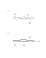
- (A) and (B) are partial cross-sectional views of the electrical conductivity measuring device, respectively.
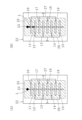
- (A) and (B) are explanatory diagrams each showing how the liquid L moves through the flow path.
- (A) and (B) are electron microscope images taken of the first electrode formed on the sheet.
- (A) and (B) are explanatory diagrams each showing a process for forming a flow path in a sheet. It is an explanatory view showing a process of forming a channel in a sheet using another mold.
- FIG. 2 is an explanatory diagram showing the results of a first experiment.
- FIG. 3 is an explanatory diagram showing the results of a second experiment.
- FIG. 7 is an explanatory diagram showing the results of a third experiment.
- an electrical conductivity measuring device 10 measures the electrical conductivity level of the liquid L.
- a device for measuring electrical conductivity values which includes a channel 11 made of a material capable of absorbing liquid L, first electrodes 12, 13, 14, 15, and second electrodes provided alternately at intervals. 16, 17, 18, and 19, an application section 20 that applies a voltage to the first electrodes 12, 13, 14, and 15, and a calculation section 21 that derives the electric value of the liquid L. This will be explained in detail below.
- the liquid L is not particularly limited, and may be, for example, a body fluid such as blood or saliva, or an electrolyte.
- a body fluid such as blood or saliva
- an electrolyte an example of a liquid containing water
- the conductivity value indicating the electrical conductivity level of the liquid L is a value indicating the ease or difficulty of conducting electricity of the liquid L. Examples of the conductivity value include electrical conductivity, electrical resistivity, and electrical conductivity. and values that are correlated with electrical resistivity.
- the first electrodes 12, 13, 14, 15 and the second electrodes 16, 17, 18, 19 are made of a material capable of absorbing the liquid L, as shown in FIGS. It is provided on one side (front side) of the formed sheet 22.
- the sheet 22 is made of paper or nonwoven fabric made of fibers that are lyophilic to the liquid L (having a high affinity for the liquid L), and is deformed by pressing.
- the rectangular sheet 22 has a linear channel 11 and a liquid supply section 23 connected to one end of the channel 11 and circular in plan view. Therefore, the channel 11 is made of paper or nonwoven fabric made of lyophilic fibers. Further, the liquid supply section 23 is also capable of absorbing the liquid L.
- the liquid L is supplied to the liquid supply part 23, the liquid L is absorbed into the liquid supply part 23, as shown in FIG. 3(A), and a part or most of it is absorbed as shown in FIG. 3(B). Then, the liquid L is absorbed into the flow path 11 (moves to the flow path 11), and a part or most of the liquid L absorbed into the flow path 11 moves along the flow path 11 toward the other end of the flow path 11.
- the sheet 22 has a flow path 11, and around the flow path 11 of the sheet 22, the liquid L absorbed in the liquid supply portion 23 and the flow path 11 flows outside the liquid supply portion 23 or A lyophobic portion 25 is formed to prevent the liquid from flowing out of the flow path 11.
- the lyophobic portion 25 is formed by impregnating a predetermined region of the sheet 22 with a hydrophobic liquid (or an oleophobic liquid if the liquid L contains oil).
- a hydrophobic liquid for example, a fluorine coating agent, an oil-based paint, or a wax can be employed.
- fluorine coating agents examples include Fluorosurf (registered trademark) manufactured by Fluoro Technology Co., Ltd.
- oil-based paints include oil-based Top Guard (“Top Guard” is a registered trademark) manufactured by Campehapio Co., Ltd.
- the first electrodes 12, 13, 14, 15 and the second electrodes 16, 17, 18, 19 are connected to the channel portion 11 on one side of the sheet 22, respectively, as shown in FIGS. 1 and 2(B). These are line-shaped metal plates (copper plates in this embodiment) that are orthogonally crossed (crossed) and are spaced apart and parallel to each other with some of them in contact with the flow path 11. Towards the end, the second electrode 16, the first electrode 12, the second electrode 17, the first electrode 13, the second electrode 18, the first electrode 14, the second electrode 19 and the first The electrodes 15 are sequentially arranged at equal pitches.
- the flow path 11 has a region (hereinafter referred to as " An electrode non-contact area (also referred to as an “electrode non-contact area”) protrudes and is exposed on one side of the sheet 22.
- the area of the flow path 11 that the first electrode 12 contacts (hereinafter also referred to as “electrode contact area”) is covered with the first electrode 12 on one side, as shown in FIG. 2(B). ing.
- This also applies to each region of the flow path 11 where the first electrodes 13, 14, 15 and the second electrodes 16, 17, 18, 19 are in contact. That is, the metal forming the first electrodes 12 , 13 , 14 , 15 and the second electrodes 16 , 17 , 18 , 19 includes some fibers of the flow path 11 .
- Both the electrode non-contact area and the electrode contact area of the channel 11 are covered with a lyophobic portion 25 from the other surface side (back side) to both side surfaces, as shown in FIGS. 2(A) and 2(B). . Therefore, the liquid L absorbed in the channel 11 moves along the channel 11 while being prevented from flowing out of the channel 11, as shown in FIGS. 3(A) and 3(B). .
- the entire circumference of the cross section of the flow path 11 is covered with the lyophobic portion 25.
- only both side surfaces of the flow path 11 may be covered by the lyophobic portion 25 (that is, the other side of the flow path 11 does not need to be covered by the lyophobic portion 25).
- most of the first electrode 12 is formed in a state that is soaked into the sheet 22, as shown in FIGS. 4(A) and 4(B), and includes some fibers of the sheet 22. are doing.
- This also applies to the first electrodes 13, 14, 15 and the second electrodes 16, 17, 18, 19. That is, the first electrodes 12, 13, 14, 15 and the second electrodes 16, 17, 18, 19 are each made of metal that includes some fibers of the sheet 22.
- cracks are formed in the first electrodes 12, 13, 14, 15 and the second electrodes 16, 17, 18, 19, respectively, into which the liquid L moving through the flow path 11 flows. There is. By forming such cracks in the first electrodes 12, 13, 14, 15 and the second electrodes 16, 17, 18, 19, the relationship between the liquid L and the first electrodes is greater than in the case where no cracks are formed. The contact area between the electrodes 12, 13, 14, 15 and the second electrodes 16, 17, 18, 19 is increased.
- the first electrodes 12, 13, 14, 15 are connected to the application unit 20 via a conducting wire 26, and the second electrodes 16, 17, 18, 19 are connected to a conducting wire 27 and an AD (not shown). It is connected to the calculation unit 21 via a converter.
- the application unit 20 is designed to be able to apply an alternating current voltage of a predetermined magnitude to the first electrodes 12 , 13 , 14 , 15 via a conducting wire 26 . Note that an application unit that applies a DC voltage may be employed.
- the calculation unit 21 can be configured to include, for example, a CPU, a memory, and an interface into which electrical signals are input, and the calculation unit 21 can be configured to include, for example, a CPU, a memory, and an interface into which electrical signals are input. It is designed so that the conductivity value of the liquid L can be derived based on the voltage signal (in this embodiment, the voltage signal).
- the electrical conductivity measuring device 10 measures the electrical conductivity value of the liquid L through the following steps S1 to S7.
- Step S1 The application unit 20 applies a voltage of a predetermined magnitude to the first electrodes 12, 13, 14, and 15.
- Step S2 A predetermined amount of liquid L is dropped into the liquid supply section 23, and the liquid L is absorbed into the liquid supply section 23.
- the liquid L absorbed by the liquid supply part 23 moves to one end of the flow path 11, as shown in FIGS. Moving.
- Step S3 The liquid L (the leading part of the liquid L) moving through the flow path 11 reaches the first electrode 12 via the second electrode 16, as shown in FIG. 3(B). Thereby, the second electrode 16 and the first electrode 12 are electrically connected via the liquid L absorbed in the region between the second electrode 16 and the first electrode 12 of the flow path 11, An electrical signal is output from the second electrode 16.
- Step S4 The calculation unit 21 acquires the electric signal from the second electrode 16 via the AD converter, and calculates the electric resistance value between the second electrode 16 and the first electrode 12 (
- the electrical resistance value also referred to as “one section electrical resistance value”
- the electrical resistivity which is an example of the conductivity value of the liquid L, is derived based on the electrical resistance value.
- the calculation unit 21 calculates the detected R1 ⁇ 1 is calculated by substituting ⁇ 1 into Equation 1 below. Note that the constants S and D are stored in the calculation unit 21 in advance.
- Step S5 The liquid L moving through the channel 11 passes through the first electrode 12 and reaches the second electrode 17, and the second electrode 16, the first electrode 12, and the second electrode 17 are electrically connected via the liquid L absorbed in the region between the second electrodes 16 and 17 of the flow path 11, the calculation unit 21 outputs the output from the second electrodes 16 and 17.
- An electrical signal is acquired via an AD converter. At this time, the second electrodes 16 and 17 are connected in parallel.
- the arithmetic unit 21 detects that the liquid L has reached the second electrode 17 when the magnitude of the acquired electric signal exceeds a predetermined value, and the distance between the second electrodes 16 and 17 is increased.
- the electrical resistance value (hereinafter also referred to as "two-section electrical resistance value”) is detected, and the conductivity value of the liquid L is derived.
- the distance between the second electrodes 16 and 17 is twice the distance between the second electrode 16 and the first electrode 12, so it becomes 2D.
- the theoretical value of the electrical resistance value in two sections is half the electrical resistance value in one section. Assuming that the electrical resistance value in the two sections is R2 and the electrical resistivity is ⁇ 2, the calculation unit 21 calculates ⁇ 2 by substituting the detected R2 into Equation 2 below.
- Step S6 After that, the calculation unit 21 calculates the electrical resistivity of the liquid L each time the liquid L moving through the channel 11 reaches the first electrode 13, the second electrode 18, etc.
- the number of electrical resistivities determined by the calculation unit 21 is assumed to be N.
- Step S7 The calculation unit 21 determines the average value of the N (plural) electrical resistivities determined as the final electrical resistivity of the liquid L. Then, the calculation unit 21 determines the viscosity of the liquid L based on the final electrical resistivity of the liquid L using Walden's law.
- the electrical conductivity measuring device 10 is manufactured through the following steps (the method for manufacturing the electrical conductivity measuring device 10 has the following steps).
- Step S11 Perform silk screen printing on one side of the sheet 22 to apply conductivity to the locations where the first electrodes 12, 13, 14, 15, second electrodes 16, 17, 18, 19 and conductive wires 26, 27 are to be formed. Apply a paste (for example, silver paste).
- a paste for example, silver paste
- Step S12 By plating the sheet 22, a copper layer is provided on the part on one side of the sheet 22 where the conductive paste is applied, and the area where the flow path 11 is planned to be formed on the one side of the sheet 22 (the area where the flow path is planned to be formed) is formed.
- First electrodes 12, 13, 14, 15 and second electrodes 16, 17, 18, 19 are provided at intervals, and conductive wires 26, 27 are formed on one side of the sheet 22.
- Step S13 As shown in FIG. 5A, a lyophobic agent Q is applied to one side of a plate-shaped mold 30 in which through-holes 29 corresponding to the channel 11 and the liquid supply section 23 are formed.
- Step S14 The mold 30 is arranged horizontally so that the one side coated with the lyophobic agent Q is positioned on the lower side, and the horizontally arranged sheet 22 with the one side applied on the upper side is placed below the mold 30.
- Two sheet-shaped cushioning materials 31 and 32 are provided directly below the sheet 22, and with a sheet-shaped protective material 33 placed directly above the mold 30, the protective material 33, the mold 30, the sheet 22, and the buffer The materials 31 and 32 are stacked and placed between an upper mold 34 and a lower mold 35 of a press machine.
- Step S15 Push down the upper mold 34 and apply pressure to the protective material 33, the mold 30, the sheet 22, and the cushioning materials 31 and 32 with the upper mold 34 and the lower mold 35, as shown in FIG. 5(B).
- one side of the mold 30 is pressed against one side (upper side) of the sheet 22, and the lyophobic agent Q is impregnated into the sheet 22.
- the lyophobic agent Q has not reached the other side of the sheet 22 at this point.
- Step S16 The sheet 22 impregnated with the lyophobic agent Q from one side is taken out from the press, and the lyophobic agent Q is applied to the other side of the sheet 22 with a brush or the like.
- Step S17 The sheet 22 is heated at 130° C. to harden the lyophobic agent Q.
- the channel 11 and the liquid supply section 23 are formed in the region of the sheet 22 corresponding to the through hole 29 of the mold 30, and the lyophobic section 25 is provided around the channel 11 of the sheet 22.
- a layer in which the lyophobic agent Q is cured is formed on the upper surface side of the first electrodes 12, 13, 14, 15 and the second electrodes 16, 17, 18, 19, but as shown in FIG. In this example, the description of the layer in which the lyophobic agent Q is cured is omitted.
- the method for manufacturing the electrical conductivity measuring device 10 is to press one side of the mold 30 coated with the lyophobic agent Q onto one surface of the sheet 22, and to The flow path 11 is formed in the sheet 22, and a lyophobic portion 25 is provided around the flow path 11 in the sheet 22.
- the target is a flow path where the amount of liquid L used for measuring the conductivity value is 20 ⁇ L
- the surface of the area where the flow path is planned to be formed is masked with tape, and the lyophobic agent is applied to the area where the flow path is planned to be formed. It has been confirmed that it is possible to measure the conductivity value of the liquid L even if it is applied to the sheet from the surface side to form a flow path.
- the method for manufacturing the electrical conductivity measuring device 10 includes a step of applying a lyophobic agent Q to an area other than the groove 37 on one side of the mold 38, and applying a lyophobic agent Q to one side of the sheet 22.
- Step S18 Connect the applying section 20 and the calculating section 21 to the conducting wires 26 and 27, respectively. Thereby, the electrical conductivity measuring device 10 is completed.
- the method for manufacturing the electrical conductivity measuring device 10 described above includes forming the first electrodes 12, 13, 14, 15 and the second electrodes 16, 17, 18, 19 on the sheet 22, and then forming the flow channels 11 on the sheet 22.
- the first electrodes 12, 13, 14, 15 and the second electrodes 16, 17, 18, 19 may be formed on the sheet 22 provided with the flow path 11.
- the first electrodes 12, 13, 14, 15 and the second electrodes 16, 17, 18, 19 which are in contact with the region of the sheet 22 where the flow path 11 is formed, are spaced apart. It will be provided with a blank space.
- a filter paper having a filtration time of 300 seconds or less, a water absorption of 5 cm or more, and a thickness of 0.3 mm or less is used as the sheet 22 .
- the water filtration time is based on JISP3801, and the water absorption rate means the height to which water rises in 10 minutes when a part of the sheet 22 in an upright state is immersed in water at 20°C.
- the filtration time of the sheet 22 exceeds 300 seconds, the ability of the flow path 11 to move the liquid L (the liquid L contains water) is low, and it takes time to measure the conductivity value.
- the lyophobic portion 25 cannot be stably formed by the method of manufacturing the electrical conductivity measuring device 10 described above. occurs. This is because the lyophobic agent Q (the lyophobic agent Q is a hydrophobic agent) is difficult to penetrate into the sheet 22, and the lyophobic portion 25 cannot be stably formed.
- Sample P2 was different from sample P1 in that it had five first and second electrodes, and the distance between adjacent first and second electrodes was 2.5 mm.
- Sample P3 differs from sample P2 in that the filter paper has hydrophobicity and that the filter paper was formed by hydrophilic treatment of the filter paper.
- four types of experimental solutions were prepared by adding sucrose to physiological saline. Each experimental solution had a different concentration of sucrose and a different viscosity. Note that in samples P2 and P3 (same as sample P1), most of the first and second electrodes were formed within the filter paper, and included fibers constituting the filter paper.
- the experimental solution was dropped into one end of the flow path of samples P2 and P3, and the electrical resistance value between the conductive parts connected to the five first electrodes and the conductive parts connected to the five second electrodes was measured. was measured, and the electrical resistivity was calculated from the measured electrical resistance value. Thereafter, the calculated electrical resistivity was compared with the viscosity coefficient measured in advance for each experimental solution. The comparison results are shown in FIG. From the comparison results, it was confirmed that there is a correlation between the electrical resistivity and the viscosity of the experimental solution for both samples P2 and P3, and that sample P2 has a higher detection resolution for the viscosity of the experimental solution than sample P3. Ta.
- ⁇ Third experiment> In the third experiment, a linear and elongated sample P4 with a width of 1 mm was used, which was obtained by cutting out the filter paper of sample P2. A pin-shaped electrode is brought into contact with each of two locations spaced apart in the longitudinal direction of sample P4, and the experimental solution used in the second experiment is dropped onto one end of sample P4. The electrical resistance value between the first and second electrodes (corresponding to the first and second electrodes) was measured, and the electrical resistivity was calculated from the measured electrical resistance value. This calculation of electrical resistivity was performed for four types of experimental solutions having different viscosity coefficients in each case in which the state of contact of the pin-shaped electrode with sample P4 was changed.
- sample P2 represents the experimental results for sample P2 in the second experiment
- sample P4 point contact
- sample P4 represents the experimental results when the tip of the pin-shaped electrode was brought into contact with sample P4.
- sample P4 line contact
- sample P4 is an experiment in which the side of a pin-shaped electrode was brought into linear contact with sample P4 (at this time, each pin-shaped electrode was arranged perpendicular to sample P4). represents the result.
- the vertical axis represents the measured electrical resistance value as a relative value
- the horizontal axis represents the viscosity of the experimental solution as a relative value.
- sample P4 point contact
- sample P4 line contact
- the present invention is not limited to the above-described embodiments, and any changes in conditions that do not depart from the gist are within the scope of the present invention.
- the first electrode may be provided on both one side and the other side of the sheet, and the first electrodes provided on the one side and the other side, respectively, may be electrically connected.
- a flow path may be formed by performing lyophilic treatment on a sheet that does not absorb the target liquid. It is not always necessary to form a flow path in the sheet; for example, a hydrophilic string-like object may be fixed to a hydrophobic substrate and the string-like object may be used as the flow path.
- the flow path does not need to be made of paper or nonwoven fabric, and may be made of, for example, molded wood chips or urethane.
- the first and second electrodes do not need to have cracks into which the liquid moving through the flow path flows.
- the measurement resolution of the conductivity value is lower than when the crack is formed.
- the first and second electrodes can also be formed by a vapor phase method such as plasma CVD or vapor deposition.
- the measurement resolution of the conductivity value is lower than when forming the first and second electrodes by plating (liquid phase method).
- microprocessed resin is used to measure the electrical conductivity value of a liquid and to measure the viscosity of a liquid based on the electrical conductivity value of the liquid. It can be done without doing anything. Therefore, for example, it is possible to commercialize a measurement kit that is priced on the premise that people measure the viscosity of body fluids every day in ordinary households.
Landscapes
- Physics & Mathematics (AREA)
- General Physics & Mathematics (AREA)
- Chemical & Material Sciences (AREA)
- Chemical Kinetics & Catalysis (AREA)
- Electrochemistry (AREA)
- Health & Medical Sciences (AREA)
- Life Sciences & Earth Sciences (AREA)
- Analytical Chemistry (AREA)
- Biochemistry (AREA)
- General Health & Medical Sciences (AREA)
- Immunology (AREA)
- Pathology (AREA)
- Investigating Or Analyzing Materials By The Use Of Electric Means (AREA)
Abstract
液体の電気伝導レベルを表す電導値を計測する電気伝導性測定装置10において、液体を吸収可能な素材からなる流路11と、流路11に接触した状態で間隔を空けて設けられた第1の電極12~15及び第2の電極16~19と、第1の電極12~15に電圧を印加する印加部20と、流路11に吸収された液体を介して電気的に接続された第1の電極12~15及び第2の電極16~19間の電気抵抗値を検出し、液体の電導値を導出する演算部21とを備える。
Description
本発明は、液体の電気伝導レベルを計測する電気伝導性測定装置及びその製造方法に関する。
糖尿病や高脂血症等の生活習慣病の患者は日々の状態確認が重要である。糖尿病については家庭での使用を前提とした血糖値計測器が普及している。これに対し、高脂血症等、糖尿病以外の生活習慣病については、家庭で状態を確認する仕組みが確立しておらず、状態の確認には医療機関での診断や検査が必要となる。ここで、血液の粘性及び生活習慣病の間には相関があることが分かりつつあるため、血液の粘性を簡易的に計測できる仕組みが確立できれば、家庭で生活習慣病の状態を確認できるようになることが期待される。
また、唾液の各成分(コルチゾール、DHEA、テストステロン等)はストレスに応じて量が変化する。唾液の各成分の含有量は唾液の粘性に影響を与えることから、唾液の粘性の測定によりストレスの評価が可能である。
従って、体液の粘性の計測は人の健康状態の確認に有効である。体液の粘性は、例えば、特許文献1に記載された体液粘性測定装置を用いて計測できる。
従って、体液の粘性の計測は人の健康状態の確認に有効である。体液の粘性は、例えば、特許文献1に記載された体液粘性測定装置を用いて計測できる。
当該装置は、体液を流す流路が形成されたチップを有し、体液の粘性が計測されるごとにチップの交換ができるように設計されている。また、当該装置は、液体の電気伝導率を基にその液体の粘性を評価できるというWalden則に基づいて、電気伝導率や電気抵抗率等の電気伝導のしやすさが分かる物理量(以下、「電気伝導値」とも言う)から体液の粘性を評価する。
しかしながら、樹脂板等に微細な加工をして製造されるチップは一定以上の製造コストを要し、例えば、当該装置を用いて家庭で体液の粘性を毎日計測したい患者にとっては、経済的負担が大きいという問題があった。
本発明は、かかる事情に鑑みてなされたもので、樹脂体に微細な加工がなされたチップを用いることなく、安価に液体の電気伝導値を計測可能な電気伝導性測定装置及びその製造方法を提供することを目的とする。
本発明は、かかる事情に鑑みてなされたもので、樹脂体に微細な加工がなされたチップを用いることなく、安価に液体の電気伝導値を計測可能な電気伝導性測定装置及びその製造方法を提供することを目的とする。
前記目的に沿う第1の発明に係る電気伝導性測定装置は、液体の電気伝導レベルを表す電導値を計測する電気伝導性測定装置において、前記液体を吸収可能な素材からなる流路と、前記流路に接触した状態で間隔を空けて設けられた第1、第2の電極と、前記第1の電極に電圧を印加する印加部と、前記流路に吸収された前記液体を介して電気的に接続された前記第1、第2の電極間の電気抵抗値を検出し、前記液体の前記電導値を導出する演算部とを備える。
前記目的に沿う第2の発明に係る電気伝導性測定装置の製造方法は、液体の電気伝導レベルを表す電導値を計測する電気伝導性測定装置の製造方法において、貫通孔が形成された金型の一側面に疎液剤を塗布する工程と、前記液体を吸収可能なシートの一面側に、前記金型の一側面を押し付けて、前記シートの前記貫通孔に対応する領域に前記液体を吸収する流路を形成し、前記シートの該流路の周囲に該流路に吸収された前記液体が該流路外に流出するのを防止する疎液部を設ける工程とを有する。
前記目的に沿う第3の発明に係る電気伝導性測定装置の製造方法は、液体の電気伝導レベルを表す電導値を計測する電気伝導性測定装置の製造方法において、一側面に溝が形成された金型の該一側面に疎液剤を塗布する工程と、前記液体を吸収可能なシートの一面側に、前記金型の一側面を押し付けて、前記シートの前記溝に対応する領域に前記液体を吸収する流路を形成し、前記シートの該流路の周囲に該流路に吸収された前記液体が該流路外に流出するのを防止する疎液部を設ける工程とを有する。
第1の発明に係る電気伝導性測定装置は、液体を吸収可能な素材からなる流路と、流路に接触した状態で間隔を空けて設けられた第1、第2の電極と、第1の電極に電圧を印加する印加部と、流路に吸収された液体を介して電気的に接続された第1、第2の電極間の電気抵抗値を検出し、液体の電導値を導出する演算部とを備えるので、例えば、流路を紙によって形成でき、樹脂体に微細な加工がなされたチップを用いることなく、安価に液体の電気伝導値を計測可能である。
第2の発明に係る電気伝導性測定装置の製造方法は、貫通孔が形成された金型の一側面に疎液剤を塗布する工程と、液体を吸収可能なシートの一面側に、金型の一側面を押し付けて、シートの貫通孔に対応する領域に液体を吸収する流路を形成し、シートの流路の周囲に流路に吸収された液体が流路外に流出するのを防止する疎液部を設ける工程とを有する。また、第3の発明に係る電気伝導性測定装置の製造方法は、一側面に溝が形成された金型の一側面に疎液剤を塗布する工程と、液体を吸収可能なシートの一面側に、金型の一側面を押し付けて、シートの溝に対応する領域に液体を吸収する流路を形成し、シートの流路の周囲に流路に吸収された液体が流路外に流出するのを防止する疎液部を設ける工程とを有するので、樹脂体に微細な加工がなされたチップを用いることなく、安価に液体の電気伝導値を計測可能な電気伝導性測定装置を製造できる。
続いて、添付した図面を参照しつつ、本発明を具体化した実施例につき説明し、本発明の理解に供する。
図1、図2(A)、(B)、図3(A)、(B)に示すように、本発明の一実施例に係る電気伝導性測定装置10は、液体Lの電気伝導レベルを表す電導値を計測する装置であって、液体Lを吸収可能な素材からなる流路11と、間隔を空けて交互に設けられた第1の電極12、13、14、15、第2の電極16、17、18、19と、第1の電極12、13、14、15に電圧を印加する印加部20と、液体Lの電動値を導出する演算部21とを備えている。以下、詳細に説明する。
図1、図2(A)、(B)、図3(A)、(B)に示すように、本発明の一実施例に係る電気伝導性測定装置10は、液体Lの電気伝導レベルを表す電導値を計測する装置であって、液体Lを吸収可能な素材からなる流路11と、間隔を空けて交互に設けられた第1の電極12、13、14、15、第2の電極16、17、18、19と、第1の電極12、13、14、15に電圧を印加する印加部20と、液体Lの電動値を導出する演算部21とを備えている。以下、詳細に説明する。
液体Lは特に限定されず、例えば、血液や唾液等の体液であってもよいし、電解液であってもよい。以下、特に記載しない限り、液体Lは体液(水分を含む液体の一例)として説明する。
液体Lの電気伝導レベルを表す電導値とは、液体Lの電気の通しやすさ又は電気の通しにくさを示す値であり、電導値として、例えば、電気伝導率、電気抵抗率、電気伝導率と相関がある値、及び、電気抵抗率と相関がある値が挙げられる。
液体Lの電気伝導レベルを表す電導値とは、液体Lの電気の通しやすさ又は電気の通しにくさを示す値であり、電導値として、例えば、電気伝導率、電気抵抗率、電気伝導率と相関がある値、及び、電気抵抗率と相関がある値が挙げられる。
第1の電極12、13、14、15及び第2の電極16、17、18、19は、図1、図2(A)、(B)に示すように、液体Lを吸収可能な素材によって形成されたシート22の一面側(表面側)に設けられている。
本実施例において、シート22は液体Lに対し親液性を有する(液体Lとの親和性が大きい)繊維によって形成された紙又は不織布からなり、プレス加工により変形する。
本実施例において、シート22は液体Lに対し親液性を有する(液体Lとの親和性が大きい)繊維によって形成された紙又は不織布からなり、プレス加工により変形する。
矩形状のシート22は、直線的な流路11と、流路11の一端部に連結された平面視して円形の給液部23を有している。従って、流路11は親液性を有する繊維によって形成された紙又は不織布からなっている。
また、給液部23も、液体Lを吸収可能である。給液部23に液体Lが供給されると、液体Lは、図3(A)に示すように、給液部23に吸収され、その一部又は大半が、図3(B)に示すように、流路11に吸収され(流路11へ移動し)、流路11に吸収された液体Lの一部又は大半が流路11を流路11の他端部に向けて移動する。
また、給液部23も、液体Lを吸収可能である。給液部23に液体Lが供給されると、液体Lは、図3(A)に示すように、給液部23に吸収され、その一部又は大半が、図3(B)に示すように、流路11に吸収され(流路11へ移動し)、流路11に吸収された液体Lの一部又は大半が流路11を流路11の他端部に向けて移動する。
シート22は、図1に示すように、流路11を有し、シート22の流路11の周囲には、給液部23及び流路11に吸収された液体Lが給液部23外又は流路11外に流出するのを防止する疎液部25が形成されている。疎液部25は、シート22の所定領域に疎水液(液体Lが油分を含むものであれば、疎油液)を浸み込ませて形成されている。疎水液として、例えば、フッ素コーティング剤、油性塗料又はワックスを採用可能である。フッ素コーティング剤として、例えば、株式会社フロロテクノロジーのフロロサーフ(登録商標)が挙げられ、油性塗料として、例えば、株式会社カンペハピオの油性トップガード(「トップガード」は登録商標)が挙げられる。
第1の電極12、13、14、15及び第2の電極16、17、18、19はそれぞれ、図1、図2(B)に示すように、シート22の一面側に流路部11に直交(交差)して一部が流路11に接触した状態で間隔を空けて平行に設けられた線分状の金属板(本実施例では銅板)であり、流路11の一端部から他端部に向けて、第2の電極16、第1の電極12、第2の電極17、第1の電極13、第2の電極18、第1の電極14、第2の電極19及び第1の電極15が順に等ピッチで配されている。
流路11は、図2(A)に示すように、第1の電極12、13、14、15及び第2の電極16、17、18、19のいずれも接触していない領域(以下、「電極非接触領域」とも言う)が、シート22の一面側に突出し露出している。これに対し、流路11の第1の電極12が接触する領域(以下、「電極接触領域」とも言う)は、図2(B)に示すように、一面側が第1の電極12に覆われている。これは、第1の電極13、14、15及び第2の電極16、17、18、19が接触する流路11の各領域についても同様である。即ち、第1の電極12、13、14、15及び第2の電極16、17、18、19を形成する金属は、流路11の一部の繊維を内包している。
流路11の電極非接触領域及び電極接触領域は共に、図2(A)、(B)に示すように、他面側(裏面側)から両側面側にかけて疎液部25により覆われている。そのため、流路11に吸収された液体Lは、図3(A)、(B)に示すように、流路11外に流出するのを防止された状態で、流路11に沿って移動する。ここで、流路11を移動する液体Lが流路11から流出するのを防止する観点では、流路11の断面の全周(流路11の一面側を含む)が疎液部25によって覆われるようにしてもよいし、流路11の両側面側のみが疎液部25によって覆われるようにしてもよい(即ち、流路11の他面側は疎液部25により覆われている必要はない)。
本実施例では、第1の電極12の大半が、図4(A)、(B)に示すように、シート22内に浸み込んだ状態で形成され、シート22の一部の繊維を内包している。これは、第1の電極13、14、15及び第2の電極16、17、18、19についても同様である。即ち、第1の電極12、13、14、15及び第2の電極16、17、18、19はそれぞれ、シート22の一部の繊維を内包した金属からなっている。
また、本実施例では、第1の電極12、13、14、15及び第2の電極16、17、18、19にはそれぞれ、流路11を移動する液体Lが流入する割れが形成されている。第1の電極12、13、14、15及び第2の電極16、17、18、19にこのような割れを形成することにより、割れを形成しない場合に比べて、液体Lと第1の電極12、13、14、15及び第2の電極16、17、18、19それぞれとの間の接触面積が大きくなるようにしている。
第1の電極12、13、14、15は、図1に示すように、導線26を介して印加部20に接続され、第2の電極16、17、18、19は導線27及び図示しないAD変換器経由で演算部21に接続されている。
印加部20は導線26を介して所定の大きさの交流電圧を第1の電極12、13、14、15に印加可能に設計されている。なお、直流電圧を印加する印加部を採用してもよい。
印加部20は導線26を介して所定の大きさの交流電圧を第1の電極12、13、14、15に印加可能に設計されている。なお、直流電圧を印加する印加部を採用してもよい。
演算部21は、例えば、CPU、メモリ及び電気信号が入力されるインターフェース等を有して構成でき、第2の電極16、17、18、19から出力されAD変換器を介して取得した電気信号(本実施例では、電圧信号)を基に液体Lの電導値を導出可能に設計されている。
電気伝導性測定装置10は、以下の工程S1~S7を経て液体Lの電導値を計測する。
工程S1:印加部20が第1の電極12、13、14、15に所定の大きさの電圧を印加した状態にする。
工程S2:給液部23に所定量の液体Lを滴下し、液体Lを給液部23に吸収させる。給液部23に吸収された液体Lは、図3(A)、(B)に示すように、流路11の一端部へ移動し、流路11を流路11の他端部に向けて移動する。
工程S3: 流路11を移動する液体L(液体Lの先頭部)が、図3(B)に示すように、第2の電極16を経て、第1の電極12に達した状態となる。これにより、第2の電極16及び第1の電極12は、流路11の第2の電極16及び第1の電極12間の領域に吸収されている液体Lを介して電気的に接続され、第2の電極16から電気信号が出力される。
工程S4:演算部21は、第2の電極16からの電気信号をAD変換器経由で取得し、取得した電気信号を基に第2の電極16及び第1の電極12間の電気抵抗値(以下、「1区間の電気抵抗値」とも言う)を検出し、当該電気抵抗値を基に、液体Lの電導値の一例である電気抵抗率を導出する。
流路11の断面積をS、第2の電極16及び第1の電極12間の距離をD、1区間の電気抵抗値をR1、電気抵抗率をρ1として、演算部21は、検出したR1を以下の式1に代入してρ1を算出する。なお、定数であるS及びDは演算部21に予め記憶されている。
ρ1=(S/D)×R1 (式1)
断面積Sを正確に測定できない場合、給液部23に吸収させた液体Lの質量を液体Lの密度で割って、給液部23に吸収させた液体Lの体積を算出し、当該体積を基に流路11の1区間分に吸収された液体Lの体積Vを求め、式1の代わりに以下の式1’を用いることによってρ1を算出可能である。
ρ1=(V/D2)×R1 (式1’)
工程S5:流路11を移動する液体Lが、第1の電極12を経て、第2の電極17に達した状態になり、第2の電極16、第1の電極12及び第2の電極17が、流路11の第2の電極16、17間の領域に吸収されている液体Lを介して電気的に接続されると、演算部21は、第2の電極16、17から出力される電気信号をAD変換器経由で取得する。このとき、第2の電極16、17は並列接続された状態となる。
演算部21は、取得する電気信号の大きさが予め定めた値以上になったことにより、液体Lが第2の電極17に達したのを検知して、第2の電極16、17間の電気抵抗値(以下、「2区間の電気抵抗値」とも言う)を検出し、液体Lの電導値を導出する。
ここで、第2の電極16、17間の距離は第2の電極16及び第1の電極12間の距離の2倍のため2Dとなる。また、2区間の電気抵抗値の理論値は1区間の電気抵抗値の半分の大きさとなる。2区間の電気抵抗値をR2、電気抵抗率をρ2として、演算部21は、検出したR2を以下の式2に代入してρ2を算出する。
ρ2=(S/2D)×R2 (式2)
工程S6:その後、演算部21は、流路11を移動する液体Lが、第1の電極13、第2の電極18等に到達する度に、液体Lの電気抵抗率を求める。ここでは、演算部21によって求められた電気抵抗率の数をN個とする。
工程S7:演算部21は求めたN個(複数)の電気抵抗率の平均値を最終的な液体Lの電気抵抗率とする。そして、演算部21は最終的な液体Lの電気抵抗率を基にしてWalden則により液体Lの粘性を求める。
また、電気伝導性測定装置10は以下の工程を経て製造される(電気伝導性測定装置10の製造方法は以下の工程を有する)。
工程S11:シート22の一面側にシルクスクリーン印刷を行い、第1の電極12、13、14、15、第2の電極16、17、18、19及び導線26、27の形成予定場所に導電性ペースト(例えば、銀ペースト)を塗布する。
工程S12:シート22に対するめっき処理によって、シート22の一面側の導電性ペーストを塗布した部分に銅の層を設け、シート22の一面側の流路11の形成予定領域(流路形成予定領域)に接触した状態の第1の電極12、13、14、15、第2の電極16、17、18、19を間隔を空けて設けると共に、シート22の一面側に導線26、27を形成する。
工程S13:図5(A)に示すように、流路11及び給液部23に対応した貫通孔29が形成された板状の金型30の一面側に疎液剤Qを塗布する。
工程S14:疎液剤Qが塗布された一面側が下側に位置するように金型30を水平に配し、金型30の下方に一面側を上側に配した水平配置したシート22を配置し、シート22の直下に2枚のシート状の緩衝材31、32を設け、金型30の真上にシート状の保護材33を載せた状態で、保護材33、金型30、シート22及び緩衝材31、32を重ね、これらをプレス機の上型34及び下型35の間に配置する。
工程S15:上型34を押し下げ、図5(B)に示すように、上型34及び下型35によって、保護材33、金型30、シート22及び緩衝材31、32を挟んで圧力を与え、シート22の一面側(上面側)に、金型30の一側面を押し付けて、シート22に疎液剤Qを浸み込ませる。本実施例では、この時点で、疎液剤Qがシート22の他面側まで達していない。
工程S16:一面側から疎液剤Qが浸み込んだシート22をプレス機から取り出し、シート22の他面側に刷毛等で疎液剤Qを塗布する。
工程S17:シート22を130℃で加熱して疎液剤Qを硬化させる。これによって、シート22の金型30の貫通孔29に対応する領域に流路11及び給液部23を形成し、シート22の流路11の周囲に疎液部25を設ける。本製造方法では、第1の電極12、13、14、15及び第2の電極16、17、18、19の上面側に疎液剤Qが硬化した層が形成されるが、図2(B)では、疎液剤Qが硬化した層の記載を省略している。
従って、電気伝導性測定装置10の製造方法は、シート22の一面側に、金型30の疎液剤Qを塗布した一側面を押し付けて、シート22の金型30の貫通孔29に対応する領域に流路11を形成し、シート22の流路11の周囲に疎液部25を設ける工程を有している。
従って、電気伝導性測定装置10の製造方法は、シート22の一面側に、金型30の疎液剤Qを塗布した一側面を押し付けて、シート22の金型30の貫通孔29に対応する領域に流路11を形成し、シート22の流路11の周囲に疎液部25を設ける工程を有している。
この点、電導値の計測に使用する液体L量を微量(例えば、10μL)とすることをターゲットとした細い流路を形成する場合、流路の形成予定領域の表面をテープ等でマスキングし、疎液剤を流路の形成予定領域の表面側からシートに塗布して流路を形成する方法では、流路の形成予定領域まで疎液剤が浸入し、流路を安定的に形成することができない。よって、上記の工程S11~工程S17を経ることで、電導値の計測に使用する液体L量を微量とすることをターゲットとした細い流路11も安定的に形成可能である。
なお、電導値の計測に使用する液体L量を20μLとすることをターゲットとした流路であれば、流路の形成予定領域の表面をテープでマスキングし、疎液剤を流路の形成予定領域の表面側からシートに塗布して流路を形成しても、液体Lの電導値の計測が可能なことを確認している。
なお、電導値の計測に使用する液体L量を20μLとすることをターゲットとした流路であれば、流路の形成予定領域の表面をテープでマスキングし、疎液剤を流路の形成予定領域の表面側からシートに塗布して流路を形成しても、液体Lの電導値の計測が可能なことを確認している。
また、貫通孔29が形成された金型30を用いる代わりに、図6に示すように、流路11及び給液部23に対応した溝37が一面側に形成された板状の金型38を用いてもよい。金型38を用いる場合、電気伝導性測定装置10の製造方法は、金型38の一面側の溝37を除く領域に疎液剤Qを塗布する工程、シート22の一面側に、金型38の疎液剤Qを塗布した一側面を押し付けて、シート22の金型38の溝37に対応する領域に流路11を形成し、シート22の流路11の周囲に疎液部25を設ける工程を有する。
工程S18:導線26、27にそれぞれ印加部20及び演算部21を接続する。これにより、電気伝導性測定装置10が完成する。
上述した電気伝導性測定装置10の製造方法は、第1の電極12、13、14、15及び第2の電極16、17、18、19をシート22に形成した後に、シート22に流路11を設けるものであるが、流路11を設けたシート22に対して第1の電極12、13、14、15及び第2の電極16、17、18、19を形成するようにしてもよい。この場合、シート22に対するめっき処理によって、シート22の流路11を形成した領域に接触した状態の第1の電極12、13、14、15及び第2の電極16、17、18、19を間隔を空けて設けることとなる。
本実施例では、シート22として、ろ水時間300秒以下、吸水度5cm以上、厚み0.3mm以下のろ紙を採用している。なお、ろ水時間はJISP3801によるものであり、吸水度は立設状態のシート22の一部を20℃の水中に浸漬し10分間で水が上昇した高さを意味する。シート22のろ水時間が300秒を超える場合、流路11の液体L(液体Lは水分を含むもの)を移動させる機能が低く、電導値の計測に時間を要することとなる。また、シート22の吸水度が5cm未満の場合や、シート22の厚みが0.3mmを超える場合、上述した電気伝導性測定装置10の製造方法により、疎液部25を安定的に形成できないおそれが生じる。これは、疎液剤Q(疎液剤Qは疎水剤)がシート22に浸み込みにくく、疎液部25を安定的に形成できないためである。
次に、本発明の作用効果を確認するために行った実験について説明する。
<第1実験>
第1実験では、親水性を有するろ紙に、2個の第1の電極、2個の第2の電極、2個の第1の電極に接続された第1の導電部、2個の第2の電極に接続された第2の導電部及び流路を形成したサンプルP1を用いた。各第1の電極及び各第2の電極は銀ペーストに銅めっきを形成したもので、隣り合う第1、第2の電極間の距離は7.5mmであった。流路はろ紙に疎水液である株式会社フロロテクノロジーのフロロサーフ(登録商標)又は株式会社カンペハピオの油性トップガード(「トップガード」は登録商標)を浸み込ませて形成したもので、幅は約1mmであった。流路の一端部から他端部に向けて1つ目の第1の電極、1つ目の第2の電極、2つ目の第1の電極及び2つ目の第2の電極が順に設けられていた。ろ紙には給液部を設けなかった。
第1実験では、親水性を有するろ紙に、2個の第1の電極、2個の第2の電極、2個の第1の電極に接続された第1の導電部、2個の第2の電極に接続された第2の導電部及び流路を形成したサンプルP1を用いた。各第1の電極及び各第2の電極は銀ペーストに銅めっきを形成したもので、隣り合う第1、第2の電極間の距離は7.5mmであった。流路はろ紙に疎水液である株式会社フロロテクノロジーのフロロサーフ(登録商標)又は株式会社カンペハピオの油性トップガード(「トップガード」は登録商標)を浸み込ませて形成したもので、幅は約1mmであった。流路の一端部から他端部に向けて1つ目の第1の電極、1つ目の第2の電極、2つ目の第1の電極及び2つ目の第2の電極が順に設けられていた。ろ紙には給液部を設けなかった。
流路の一端部に約20μLの生理食塩水を滴下し、生理食塩水が流路を他端部に向かって移動する間の第1、第2の導電部間の電気抵抗値を計測した。生理食塩水の先頭部は、最終的に2つ目の第2の電極まで達した。
計測結果を図7に示す。計測結果より、電気抵抗値が3段階低下したことが確認された。
計測結果を図7に示す。計測結果より、電気抵抗値が3段階低下したことが確認された。
<第2実験>
第2実験では、2種類のサンプルP2、P3を用いた。サンプルP2は、サンプルP1に対し、第1、第2の電極をそれぞれ5個としたもので、隣り合う第1、第2の電極間の距離は2.5mmであった。サンプルP3は、サンプルP2に対して、ろ紙が疎水性を有する点、ろ紙への親水処理によってろ紙を形成した点が異なる。また、生理食塩水にショ糖を加えた4種類の実験用溶液を用意した。各実験用溶液は、ショ糖の濃度が異なり、粘性率も異なっていた。なお、サンプルP2、P3(サンプルP1も同じ)は、第1、第2の電極の大半が、ろ紙内に形成され、ろ紙を構成する繊維を内包していた。
第2実験では、2種類のサンプルP2、P3を用いた。サンプルP2は、サンプルP1に対し、第1、第2の電極をそれぞれ5個としたもので、隣り合う第1、第2の電極間の距離は2.5mmであった。サンプルP3は、サンプルP2に対して、ろ紙が疎水性を有する点、ろ紙への親水処理によってろ紙を形成した点が異なる。また、生理食塩水にショ糖を加えた4種類の実験用溶液を用意した。各実験用溶液は、ショ糖の濃度が異なり、粘性率も異なっていた。なお、サンプルP2、P3(サンプルP1も同じ)は、第1、第2の電極の大半が、ろ紙内に形成され、ろ紙を構成する繊維を内包していた。
サンプルP2、P3の流路の一端部に実験用溶液を滴下し、5個の第1の電極に接続された導電部及び5個の第2の電極に接続された導電部間の電気抵抗値を計測し、計測した電気抵抗値から電気抵抗率を算出した。その後、算出した電気抵抗率と各実験用溶液について予め計測しておいた粘性率とを比較した。
比較結果を図8に示す。比較結果より、サンプルP2、P3共に電気抵抗率と実験用溶液の粘性率間に相関があること、及び、サンプルP2はサンプルP3に比べ実験用溶液の粘性率の検出分解能が高いことが確認できた。
比較結果を図8に示す。比較結果より、サンプルP2、P3共に電気抵抗率と実験用溶液の粘性率間に相関があること、及び、サンプルP2はサンプルP3に比べ実験用溶液の粘性率の検出分解能が高いことが確認できた。
<第3実験>
第3実験では、サンプルP2のろ紙を切り取った幅1mmの直線的な細長いサンプルP4を用いた。サンプルP4の長手方向に間隔を空けた2箇所にそれぞれピン状の電極を接触させ、サンプルP4の一端部に第2の実験で使用した実験用溶液を滴下し、2つのピン状の電極(それぞれ第1、第2の電極に相当)間の電気抵抗値を計測し、計測した電気抵抗値から電気抵抗率を算出した。この電気抵抗率の算出を、ピン状の電極のサンプルP4への接触状態を変えた各ケースにおいて粘性率が異なる4種類の実験用溶液に対して行った。
第3実験では、サンプルP2のろ紙を切り取った幅1mmの直線的な細長いサンプルP4を用いた。サンプルP4の長手方向に間隔を空けた2箇所にそれぞれピン状の電極を接触させ、サンプルP4の一端部に第2の実験で使用した実験用溶液を滴下し、2つのピン状の電極(それぞれ第1、第2の電極に相当)間の電気抵抗値を計測し、計測した電気抵抗値から電気抵抗率を算出した。この電気抵抗率の算出を、ピン状の電極のサンプルP4への接触状態を変えた各ケースにおいて粘性率が異なる4種類の実験用溶液に対して行った。
実験結果を図9に示す。図9において、「サンプルP2」は第2実験におけるサンプルP2についての実験結果を表し、「サンプルP4(点接触)」はサンプルP4にピン状の電極の先端部を接触させた際の実験結果を表し、「サンプルP4(線接触)」はサンプルP4にピン状の電極の側部を線状に接触させた際(このとき、各ピン状の電極はサンプルP4に対し垂直に配した)の実験結果を表している。なお、図9において、縦軸は計測された電気抵抗値を相対値として表したものであり、横軸は実験用溶液の粘性率を相対値として表現したものである。
「サンプルP4(点接触)」の実験結果、及び、「サンプルP4(線接触)」の実験結果より、ピン状の電極を用いた場合も、2つの接触状態で、共に、電気抵抗率と実験用溶液の粘性率間に相関があることが確認された。また、「サンプルP2」は「サンプルP4(点接触)」及び「サンプルP4(線接触)」に比べ(即ち、大半がろ紙内に形成された第1、第2の電極を流路に接触させる場合、電極をろ紙の表面に接触させる場合に比べ)、実験用溶液の粘性率の検出分解能が高いことが確認できた。
以上、本発明の実施例を説明したが、本発明は、上記した実施例に限定されるものでなく、要旨を逸脱しない条件の変更等は全て本発明の適用範囲である。
例えば、第1、第2の電極はそれぞれ1つずつであってもよい。第1の電極をシートの一面側及び他面側の双方に設け、一面側及び他面側にそれぞれ設けた第1の電極を電気的に接続するようにしてもよく、これは第2の電極についても同様である。
また、対象の液体を吸収しないシートに親液処理を行って流路を形成してもよい。シートに流路を形成することは必ずしも必要でなく、例えば、疎水性を有する基板に親水性のある紐状物を固定し、その紐状物を流路としてもよい。流路は紙又は不織布からなる必要はなく、例えば、木屑を成形したものやウレタンであってもよい。
例えば、第1、第2の電極はそれぞれ1つずつであってもよい。第1の電極をシートの一面側及び他面側の双方に設け、一面側及び他面側にそれぞれ設けた第1の電極を電気的に接続するようにしてもよく、これは第2の電極についても同様である。
また、対象の液体を吸収しないシートに親液処理を行って流路を形成してもよい。シートに流路を形成することは必ずしも必要でなく、例えば、疎水性を有する基板に親水性のある紐状物を固定し、その紐状物を流路としてもよい。流路は紙又は不織布からなる必要はなく、例えば、木屑を成形したものやウレタンであってもよい。
更に、第1、第2の電極には、流路を移動する液体が流入する割れが形成されていなくてもよい。但し、第1、第2の電極に当該割れが形成されていない場合、当該割れが形成されている場合に比べて、電導値の計測分解能が低くなる。
そして、第1、第2の電極はプラズマCVDや蒸着等の気相法により形成することもできる。但し、気相法により第1、第2の電極を形成する場合、めっき処理(液相法)により第1、第2の電極を形成する場合に比べて、電導値の計測分解能が低くなる。
そして、第1、第2の電極はプラズマCVDや蒸着等の気相法により形成することもできる。但し、気相法により第1、第2の電極を形成する場合、めっき処理(液相法)により第1、第2の電極を形成する場合に比べて、電導値の計測分解能が低くなる。
本発明に係る電気伝導性測定装置及びその製造方法によれば、液体の電気伝導値の計測や液体の電気伝導値を基にした液体の粘性の計測を、微細な加工がなされた樹脂を使用することなく行うことができる。そのため、例えば、一般家庭において人が体液の粘性を毎日計測することを前提とした価格の計測キットを製品化できる。
10:電気伝導性測定装置、11:流路、12、13、14、15:第1の電極、16、17、18、19:第2の電極、20:印加部、21:演算部、22:シート、23:給液部、25:疎液部、26、27:導線、29:貫通孔、30:金型、31、32:緩衝材、33:保護材、34:上型、35:下型、37:溝、38:金型、L:液体、Q:疎液剤
Claims (9)
- 液体の電気伝導レベルを表す電導値を計測する電気伝導性測定装置において、
前記液体を吸収可能な素材からなる流路と、
前記流路に接触した状態で間隔を空けて設けられた第1、第2の電極と、
前記第1の電極に電圧を印加する印加部と、
前記流路に吸収された前記液体を介して電気的に接続された前記第1、第2の電極間の電気抵抗値を検出し、前記液体の前記電導値を導出する演算部とを備えることを特徴とする電気伝導性測定装置。 - 請求項1記載の電気伝導性測定装置において、前記流路は、親液性を有する繊維によって形成された紙又は不織布からなり、前記第1、第2の電極は、一部の前記繊維を内包した金属からなることを特徴とする電気伝導性測定装置。
- 請求項1記載の電気伝導性測定装置において、前記液体を吸収するシートが設けられ、該シートは前記流路を有し、該シートの前記流路の周囲には、該流路に吸収された前記液体が該流路外に流出するのを防止する疎液部が形成されていることを特徴とする電気伝導性測定装置。
- 請求項3記載の電気伝導性測定装置において、前記シートは、親液性を有する繊維によって形成された紙又は不織布からなり、前記第1、第2の電極は、一部の前記繊維を内包した金属からなることを特徴とする電気伝導性測定装置。
- 請求項2又は4記載の電気伝導性測定装置において、前記第1、第2の電極には、前記流路を移動する前記液体が流入する割れが形成されていることを特徴とする電気伝導性測定装置。
- 請求項1~4のいずれか1項に記載の電気伝導性測定装置において、前記液体は体液であって、前記演算部は、前記電導値を基にして前記液体の粘性を求めることを特徴とする電気伝導性測定装置。
- 液体の電気伝導レベルを表す電導値を計測する電気伝導性測定装置の製造方法において、
貫通孔が形成された金型の一側面に疎液剤を塗布する工程と、
前記液体を吸収可能なシートの一面側に、前記金型の一側面を押し付けて、前記シートの前記貫通孔に対応する領域に前記液体を吸収する流路を形成し、前記シートの該流路の周囲に該流路に吸収された前記液体が該流路外に流出するのを防止する疎液部を設ける工程とを有することを特徴とする電気伝導性測定装置の製造方法。 - 液体の電気伝導レベルを表す電導値を計測する電気伝導性測定装置の製造方法において、
一側面に溝が形成された金型の該一側面に疎液剤を塗布する工程と、
前記液体を吸収可能なシートの一面側に、前記金型の一側面を押し付けて、前記シートの前記溝に対応する領域に前記液体を吸収する流路を形成し、前記シートの該流路の周囲に該流路に吸収された前記液体が該流路外に流出するのを防止する疎液部を設ける工程とを有することを特徴とする電気伝導性測定装置の製造方法。 - 請求項7又は8記載の電気伝導性測定装置の製造方法において、前記シートに対するめっき処理によって、前記シートの流路形成予定領域又は前記流路が形成された領域に接触した状態の金属製の第1、第2の電極を間隔を空けて設ける工程を、更に有することを特徴とする電気伝導性測定装置の製造方法。
Applications Claiming Priority (2)
| Application Number | Priority Date | Filing Date | Title |
|---|---|---|---|
| JP2022-078911 | 2022-05-12 | ||
| JP2022078911A JP7527027B2 (ja) | 2022-05-12 | 2022-05-12 | 電気伝導性測定装置 |
Publications (1)
| Publication Number | Publication Date |
|---|---|
| WO2023218733A1 true WO2023218733A1 (ja) | 2023-11-16 |
Family
ID=88729909
Family Applications (1)
| Application Number | Title | Priority Date | Filing Date |
|---|---|---|---|
| PCT/JP2023/007078 Ceased WO2023218733A1 (ja) | 2022-05-12 | 2023-02-27 | 電気伝導性測定装置及びその製造方法 |
Country Status (2)
| Country | Link |
|---|---|
| JP (1) | JP7527027B2 (ja) |
| WO (1) | WO2023218733A1 (ja) |
Citations (8)
| Publication number | Priority date | Publication date | Assignee | Title |
|---|---|---|---|---|
| WO2013181656A1 (en) * | 2012-06-01 | 2013-12-05 | President And Fellows Of Harvard College | Microfluidic devices formed from hydrophobic paper |
| JP2013545109A (ja) * | 2010-12-09 | 2013-12-19 | ケヴァル,アルテュール | 流体サンプル分析用のマイクロ流体デバイス |
| JP2015083963A (ja) * | 2013-09-19 | 2015-04-30 | 株式会社リコー | 流体デバイス、転写材、および流体デバイスの製造方法 |
| WO2015152287A1 (ja) * | 2014-03-31 | 2015-10-08 | 国立大学法人愛媛大学 | 機能性材料、機能性材料の製造方法および機能性液体 |
| JP2017133918A (ja) * | 2016-01-27 | 2017-08-03 | 国立大学法人九州工業大学 | 体液粘性測定装置 |
| JP3212682U (ja) * | 2017-06-22 | 2017-09-28 | 味の素株式会社 | 体液受入れ構造体およびそれを有する体液分析装置 |
| EP3225309A1 (fr) * | 2016-03-31 | 2017-10-04 | Biomérieux | Membranes d'analyse de dispositifs microfluidiques et procédé de fabrication |
| WO2021220716A1 (ja) * | 2020-04-28 | 2021-11-04 | デクセリアルズ株式会社 | 検査チップ、及びその製造方法 |
Family Cites Families (7)
| Publication number | Priority date | Publication date | Assignee | Title |
|---|---|---|---|---|
| JP2002328110A (ja) * | 2001-04-27 | 2002-11-15 | Yamatake Corp | 静電容量センサ |
| EP3225310A1 (fr) * | 2016-03-31 | 2017-10-04 | Biomérieux | Membranes d'analyse de dispositifs microfluidiques, réalisées en un matériau en fibre de verre |
| JP6762009B2 (ja) * | 2016-08-16 | 2020-09-30 | 国立大学法人九州工業大学 | 体液粘性測定装置 |
| KR102117950B1 (ko) * | 2018-11-08 | 2020-06-02 | 계명대학교 산학협력단 | 바이오센서용 전극 제조방법 및 그 바이오센서용 전극 |
| JP2021032659A (ja) * | 2019-08-22 | 2021-03-01 | 国立大学法人信州大学 | センサ用流路機構 |
| JP2023025870A (ja) * | 2021-08-11 | 2023-02-24 | 株式会社アドバンテスト | 生乳測定器 |
| JP2023025871A (ja) * | 2021-08-11 | 2023-02-24 | 株式会社アドバンテスト | 生乳測定器およびその製造方法 |
-
2022
- 2022-05-12 JP JP2022078911A patent/JP7527027B2/ja active Active
-
2023
- 2023-02-27 WO PCT/JP2023/007078 patent/WO2023218733A1/ja not_active Ceased
Patent Citations (8)
| Publication number | Priority date | Publication date | Assignee | Title |
|---|---|---|---|---|
| JP2013545109A (ja) * | 2010-12-09 | 2013-12-19 | ケヴァル,アルテュール | 流体サンプル分析用のマイクロ流体デバイス |
| WO2013181656A1 (en) * | 2012-06-01 | 2013-12-05 | President And Fellows Of Harvard College | Microfluidic devices formed from hydrophobic paper |
| JP2015083963A (ja) * | 2013-09-19 | 2015-04-30 | 株式会社リコー | 流体デバイス、転写材、および流体デバイスの製造方法 |
| WO2015152287A1 (ja) * | 2014-03-31 | 2015-10-08 | 国立大学法人愛媛大学 | 機能性材料、機能性材料の製造方法および機能性液体 |
| JP2017133918A (ja) * | 2016-01-27 | 2017-08-03 | 国立大学法人九州工業大学 | 体液粘性測定装置 |
| EP3225309A1 (fr) * | 2016-03-31 | 2017-10-04 | Biomérieux | Membranes d'analyse de dispositifs microfluidiques et procédé de fabrication |
| JP3212682U (ja) * | 2017-06-22 | 2017-09-28 | 味の素株式会社 | 体液受入れ構造体およびそれを有する体液分析装置 |
| WO2021220716A1 (ja) * | 2020-04-28 | 2021-11-04 | デクセリアルズ株式会社 | 検査チップ、及びその製造方法 |
Non-Patent Citations (2)
| Title |
|---|
| NOVIANA EKA, OZER TUGBA, CARRELL CODY S., LINK JEREMY S., MCMAHON CATHERINE, JANG ILHOON, HENRY CHARLES S.: "Microfluidic Paper-Based Analytical Devices: From Design to Applications", CHEMICAL REVIEWS, AMERICAN CHEMICAL SOCIETY, US, vol. 121, no. 19, 13 October 2021 (2021-10-13), US , pages 11835 - 11885, XP055854824, ISSN: 0009-2665, DOI: 10.1021/acs.chemrev.0c01335 * |
| THUO MARTIN M., MARTINEZ RAMSES V., LAN WEN-JIE, LIU XINYU, BARBER JABULANI, ATKINSON MANZA B. J., BANDARAGE DINETH, BLOCH JEAN-FR: "Fabrication of Low-Cost Paper-Based Microfluidic Devices by Embossing or Cut-and-Stack Methods", CHEMISTRY OF MATERIALS, AMERICAN CHEMICAL SOCIETY, US, vol. 26, no. 14, 22 July 2014 (2014-07-22), US , pages 4230 - 4237, XP093107228, ISSN: 0897-4756, DOI: 10.1021/cm501596s * |
Also Published As
| Publication number | Publication date |
|---|---|
| JP7527027B2 (ja) | 2024-08-02 |
| JP2023167605A (ja) | 2023-11-24 |
Similar Documents
| Publication | Publication Date | Title |
|---|---|---|
| CN102985812B (zh) | 土壤的水分状态确定装置及其方法 | |
| Ibrahim et al. | Geometric parameters optimization of planar interdigitated electrodes for bioimpedance spectroscopy | |
| KR20150013197A (ko) | 센서 어레이 | |
| US9719951B1 (en) | Method and apparatus for moisture detection | |
| AU2001237587A1 (en) | Measurement of substances in liquids | |
| CN105917219B (zh) | 气体传感器元件 | |
| EP1261868A1 (en) | Measurement of substances in liquids | |
| KR20130057477A (ko) | 대칭적으로 분포된 분해물질 민감성 영역들을 갖는 전기화학적 센서 | |
| US10684245B2 (en) | Electrode arrangements for electrochemical test elements | |
| US20190376922A1 (en) | Electrode arrangements for test element integrity | |
| JP7071723B2 (ja) | 複素誘電率測定用回路、複素誘電率測定装置及び複素誘電率の測定方法 | |
| WO2023218733A1 (ja) | 電気伝導性測定装置及びその製造方法 | |
| US20130180869A1 (en) | Electrochemical test strip and method for testing a sample using the same | |
| JP2023167605A5 (ja) | ||
| Bera et al. | Studies on thin film based flexible gold electrode arrays for resistivity imaging in electrical impedance tomography | |
| CN103134456A (zh) | 膜厚测量方法及膜厚测量装置、半导体集成电路的制造方法、控制程序、可读存储介质 | |
| JP7024553B2 (ja) | 腐食環境測定装置のプローブ及び腐食環境測定装置 | |
| JP6362256B2 (ja) | イオンセンサ | |
| KR940015522A (ko) | 재료 표면 비저항 측정 방법 및 이것에 사용하기 위한 측정프로브 | |
| Bera et al. | Gold electrode sensors for Electrical Impedance Tomography (EIT) studies | |
| WO2012114706A1 (ja) | 生体試料測定装置 | |
| Singh et al. | Based two-electrode sensor fabricated by pencil drawing for glucose sensing | |
| RU2302617C1 (ru) | Датчик для измерения уровня жидкости | |
| KR20020052796A (ko) | 전기강판의 표면 절연 저항율 측정장치 | |
| JP2018204987A (ja) | 抵抗値測定冶具および抵抗値測定装置 |
Legal Events
| Date | Code | Title | Description |
|---|---|---|---|
| 121 | Ep: the epo has been informed by wipo that ep was designated in this application |
Ref document number: 23803220 Country of ref document: EP Kind code of ref document: A1 |
|
| NENP | Non-entry into the national phase |
Ref country code: DE |
|
| 122 | Ep: pct application non-entry in european phase |
Ref document number: 23803220 Country of ref document: EP Kind code of ref document: A1 |