WO2023218640A1 - 映像生成装置、及びコンピュータが読み取り可能な記憶媒体 - Google Patents
映像生成装置、及びコンピュータが読み取り可能な記憶媒体 Download PDFInfo
- Publication number
- WO2023218640A1 WO2023218640A1 PCT/JP2022/020223 JP2022020223W WO2023218640A1 WO 2023218640 A1 WO2023218640 A1 WO 2023218640A1 JP 2022020223 W JP2022020223 W JP 2022020223W WO 2023218640 A1 WO2023218640 A1 WO 2023218640A1
- Authority
- WO
- WIPO (PCT)
- Prior art keywords
- data
- video
- display screen
- generation device
- industrial machine
- Prior art date
- Legal status (The legal status is an assumption and is not a legal conclusion. Google has not performed a legal analysis and makes no representation as to the accuracy of the status listed.)
- Ceased
Links
Images


Classifications
-
- G—PHYSICS
- G05—CONTROLLING; REGULATING
- G05B—CONTROL OR REGULATING SYSTEMS IN GENERAL; FUNCTIONAL ELEMENTS OF SUCH SYSTEMS; MONITORING OR TESTING ARRANGEMENTS FOR SUCH SYSTEMS OR ELEMENTS
- G05B23/00—Testing or monitoring of control systems or parts thereof
- G05B23/02—Electric testing or monitoring
Definitions
- the present invention relates to a video generation device and a computer readable storage medium.
- a data logger Industrial machines and machines detected by sensors installed around them are recorded in a data collection device called a data logger.
- a large number of data loggers are installed in the factory to record the status of the machines in the factory.
- a PLC Programmable Logic Controller
- a numerical controller that controls a machine tool also include a recording section therein, and store control information and status information.
- Patent Document 1 states, ⁇ When the time load means acquires the control data acquired from the control device, the image data acquired from the camera, and the acoustic data acquired from the controlled device, it calculates the time at the time when each data was acquired. The added time-added control data, time-added image data, and time-added audio data are created and stored in a temporary file, and then the log data forming means creates the time-added control data, time-added sound data, and time-added control data stored in the temporary file.
- the time-added control data, time-added image data, and time-added audio data of the set closest in time are read out, and log data having time, control data, image data, and audio data is formed. By doing so, each piece of data can be played back while being synchronized.”
- images, sounds, and logs of a device to be controlled are played back while being synchronized by time.
- Patent Document 2 states that ⁇ a camera that photographs the robot is connected to the controller, and image data indicating the behavior of the robot obtained by photographing is supplied to the controller in the form of electrical signals''; ) occurs, an error record related to the error is created separately from the operation log.” According to Patent Document 2, when an event occurs when an image is photographed, the event and the image are recorded in association with each other.
- Patent Document 1 displays an image and a log at the same time, and Patent Document 2 records a log (data) when an event occurs. If you have logs and images from when the error occurred, the situation at the time of the error can be clarified and it will be useful in investigating the cause of the error.
- An image generation device that is an aspect of the present disclosure includes a video acquisition unit that acquires an image of an industrial machine, including a display screen of the industrial machine, a data acquisition unit that acquires data indicating a mechanical state of the industrial machine, and a display screen of the industrial machine.
- a screen discrimination section that discriminates the type of the display screen, a data extraction section that extracts a part of the data based on the type of display screen and the status information of the industrial machine, and a data acquisition section that uses the data extracted by the data extraction section and the data acquisition section.
- a video generation unit that generates a video that simultaneously displays the acquired video.
- a storage medium that is an aspect of the present disclosure acquires an image of an industrial machine, including a display screen of the industrial machine, and acquires data indicating a mechanical state of the industrial machine, when executed by one or more processors. , determines the type of display screen, extracts the data used to generate the video based on the type of display screen and the status information of the industrial machine, and creates a video that simultaneously displays the extracted data and the acquired video.
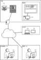
- FIG. 3 is a diagram showing the scope of application of the video generation device.
- FIG. 1 is a block diagram of a video generation device. It is an external view of a machining center. It is a table showing data extraction conditions.
- 3 is a flowchart showing a procedure for setting a tool correction amount. This is an example of a tool correction screen. It is a figure explaining the machine coordinate value of a tool measuring device.
- FIG. 3 is a diagram illustrating setting of workpiece coordinates. It is a figure showing the positional relationship of a tool and a tool measuring instrument. It is a figure explaining setting of tool length.
- FIG. 2 is a diagram showing an example of a conventional video.
- FIG. 2 is a diagram illustrating an example of a video to which the present disclosure is applied.
- FIG. 2 is a hardware configuration diagram of a video generation device.
- the image generation device acquires images of industrial machines installed in a factory and data indicating the state of the industrial machines. Video and data are stored in data loggers, PLCs, internal and external servers, numerical control devices, etc.
- the video generation device 100 acquires already accumulated data and generates a recorded video showing the operation of the industrial machine.
- the recorded video consists of images of industrial machinery and data explaining the state of the industrial machinery.
- the video generation device 100 is applied to information processing devices such as PCs (personal computers), servers, and mobile terminals.
- the video generation device 100 includes a PC used by a factory manager, a server on the cloud, a PC used by an operator of a machine manufacturer or a control machine manufacturer, and a PC used by a factory manager. This applies to, but is not limited to, mobile terminals used.
- the video generated by the video generation device 100 is utilized for management of industrial machinery (maintenance, production management, etc.).
- FIG. 2 is a block diagram of the video generation device 100.
- the video generation device 100 includes a video acquisition section 1 , a data acquisition section 2 , a screen discrimination section 3 , an extraction condition storage section 4 , a data extraction section 5 , and a video generation section 6 .
- the image acquisition unit 1 acquires images of machines and equipment in the factory from data loggers, internal and external servers, PLCs, numerical control devices, and the like.
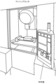
- FIG. 3 shows the appearance of the machining center.
- the machining center of the present disclosure is provided with two cameras. One camera images the workpiece attached to the table, and the other camera images the operation panel. Only the buttons and dials on the control panel may be photographed, and the display screen may be captured. Time information is added to the video acquired by the video acquisition unit 1, and it can be merged with data representing the machine state (described later). Note that in the present disclosure, video includes both moving images and still images.
- Video also includes images in which multiple still images are displayed consecutively. Further, in the present disclosure, an image of the interior of the machining center, an operation screen of the numerical control device, and an operation panel of the numerical control device are displayed side by side, but either the operation panel of the numerical control device or the operation screen of the numerical control device is displayed side by side. You may display only
- the data acquisition unit 2 acquires data regarding numerical control devices and machine tools from data loggers, internal and external servers, PLCs, numerical control devices, and the like.
- the data acquired by the data acquisition unit 2 includes status information of the numerical control device, operation input information, control information of the machine tool, and the like.
- the status information of the numerical control device is set in the internal variables of the numerical control device, and includes the mode of the numerical control device, tool offset amount, alarm, time, number of parts to be machined, modal information, position information (coordinate system), There are various types of signals.
- Operational input information includes input to the touch panel and input using physical buttons, dials, and handles.
- the machine tool control information includes physical quantities necessary for controlling the machine tool, machine tool status information, and the like.
- Control information for machine tools includes power consumption, load on servo motors, and data measured by sensors (temperature and pressure).
- the screen determination unit 3 determines the type of display screen based on the data acquired by the data acquisition unit 2 and the video acquired by the video acquisition unit 1.
- Known image analysis is used to determine the type of display screen based on the video. It may be determined what kind of screen is being displayed by image analysis. Image analysis may be used to determine information such as the button operated by the user, the type and position of the tool, the installation and position of the workpiece, and the start and end of machining.
- the data acquired by the data acquisition unit 2 includes status information of the numerical control device, operation input information of the numerical control device, control information of the machine tool, and the like.
- the status information of the numerical control device includes mode information of the numerical control device.
- the screen determination unit 3 determines the type of display screen based on the mechanical state and operation input of the numerical control device.
- the display screen can be identified by the screen ID.
- the extraction condition storage unit 4 stores data extraction conditions.
- the data to be extracted is determined by the type of display screen and the state of the numerical control device (industrial machine).
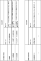
- FIG. 4 shows an example of extraction conditions.
- the upper table in Figure 4 defines the extraction conditions for the display screen type.
- “Tool data change information” is not extracted, and “Tool data change information” is not extracted. It is defined as extracting "data related to changes in machine status other than information”. Since “tool data change information” is displayed on the “tool screen,” only data that cannot be determined from the display screen is extracted.
- “work coordinate screen” it is defined that "change information of work coordinate data” is not extracted, but “data related to machine state changes other than change information of work coordinate data” is extracted. Since “workpiece coordinate data change information” is displayed on the "workpiece coordinate screen,” data that cannot be determined from the display screen is extracted.
- the data extraction section 5 extracts data based on the extraction conditions stored in the extraction condition storage section 4.
- the extracted data includes data that is always displayed in the generated video and data that is displayed only when the data value changes. If the data is to be displayed constantly, read the data periodically. In the case of data that is displayed only when the data value changes, when a change (change) in the data is detected, the extraction conditions are referred to and it is determined whether or not to extract the data.
- the data extraction unit 5 adds a time stamp to the extracted data. The timestamp indicates the time when the data changed (changed).
- the extraction conditions are conditions for excluding information that overlaps with information provided by the display screen.
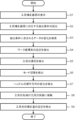
- the data extraction unit 5 detects data instructing to start setting the tool correction amount, and determines that the tool correction screen has been displayed in accordance with the instruction (step S1).
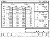
- FIG. 6 is an example of the tool correction screen.
- the tool compensation screen in Figure 6 displays a list of the tool number, tool shape compensation amount (tool length), wear compensation amount (tool length), tool shape compensation amount (tool diameter), and wear compensation amount (tool diameter). , relative coordinates, absolute coordinates, and mechanical coordinates are displayed. At the bottom of the tool offset screen, a correction amount input button and a delete button are displayed.
- the data extraction unit 5 reads extraction conditions corresponding to the tool correction screen (step S2).
- the data extraction unit 5 searches for changes in data included in the extraction conditions (step S3).
- the data extraction unit 5 detects the setting (change) of the workpiece coordinate system (absolute coordinates) with the switch of the tool measuring device as the origin based on the data acquired by the data acquisition unit 2 (step S4).
- key inputs such as “ ⁇ (upward arrow)”, “ ⁇ (downward arrow)”, “ ⁇ (leftward arrow)”, and “ ⁇ (rightward arrow)” are input, but such input signals Changes in can be determined from the video, so they are not extracted as display data.
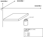
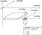
- the machine coordinates "X: 300.0", “Y: 240.0”, “Z: -380.0" of the switch of the tool measuring device are set to the workpiece coordinate origin "G55". Since the setting of the workpiece coordinate origin "G55" can be determined from the video, it is not extracted as display data.
- the data extraction unit 5 detects the selection (change) of the tool to be measured (step S5). Data regarding the tool cannot be determined from the tool correction screen shown in FIG. Therefore, data related to tools, such as "tool change: T1 ⁇ T5", is extracted as display data. Note that if a plurality of tools are selected, the processes from step S4 to step S5 are repeated a plurality of times.
- the data extraction unit 5 detects a mode switch (change) from “memory mode” to "handle mode” (step S6).
- "Memory mode” is a mode in which the numerical control device automatically operates according to a program
- "handle mode” is a mode in which the main shaft is moved by operating the handle.
- the mode extraction condition is "always display”.
- the data extraction unit 5 extracts data indicating the mode.
- the data extraction unit 5 detects a change in the operating direction of the handle (step S7).
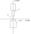
- the tool is placed directly above the tool measurer (see Figure 9). Since the operating direction of the handle cannot be determined from the video, data on the operating direction, such as "HANDLE +Z”, “HANDLE -Z”, “HANDLE +X”, and "HANDLE -X”, is extracted as display data.
- a tool is attached to the tip of the spindle.
- the tip of the tool comes into contact with the tool measuring device (step S8). Since the switch position of the tool measuring device is set to the work coordinate origin "G55", the value of the Z axis when the work coordinate origin "G55" when the tool contacts the tool measuring device is set as the origin indicates the tool length. In the example of FIG. 10, the value of the Z axis is "110.000".
- the data extraction unit 5 detects the setting (change) of the tool shape correction amount (step S9).
- the tool length correction amount for tool number "002" is set to "110.000".
- the tool length correction amount changes from “0.000" to "110.000", but since this change can be determined from the video, it is not extracted as display data.
- the video generation unit 6 merges the video acquired by the video acquisition unit 1 and the data extracted by the data extraction unit 5 based on time, and creates a screen that displays changes in the state of the machine as data. Changes in the display screen will be explained with reference to FIGS. 11 and 12.
- FIG. 11 is an example of a video generated by a conventional video generation device 100
- FIG. 12 is an example of a video generated by the video generation device 100 to which the present disclosure is applied.
- data extraction conditions are set at the time when a video is shot, and data that meets the extraction conditions is extracted as display data.
- Display data is saved with a time stamp.
- the video generation device merges video and data using time as a key, and displays the data superimposed on the video. According to the video generation device of the present disclosure, since the number of display data can be suppressed, a display screen with good visibility can be provided.
- FIG. 13 is a hardware configuration diagram of the video generation device 100.
- the video generation device 100 includes a CPU 111 that controls the video generation device 100 as a whole, a ROM 112 that records programs and data, and a RAM 113 that temporarily expands data.
- a system program recorded in the ROM 112 is read out through the ROM 112, and the entire video generation apparatus 100 is controlled in accordance with the system program.
- the nonvolatile memory 114 is backed up by, for example, a battery (not shown), so that its storage state is maintained even when the power of the video generation device 100 is turned off.
- the nonvolatile memory 114 stores various data such as programs read from external devices via the interfaces 115, 118, and 119 and user operations input via the input unit 30.
- Video generation device 1 Video acquisition unit 2 Data acquisition unit 3 Screen discrimination unit 4 Extraction condition storage unit 5 Data extraction unit 6 Video generation unit 111 CPU 113 RAM 114 Non-volatile memory
Landscapes
- Physics & Mathematics (AREA)
- General Physics & Mathematics (AREA)
- Engineering & Computer Science (AREA)
- Automation & Control Theory (AREA)
- Numerical Control (AREA)
Abstract
映像生成装置は、産業機械の表示画面を含む、前記産業機械の映像を取得し、産業機械の機械状態を示すデータを取得し、表示画面の種類を判別し、表示画面の種類と産業機械の状態情報を元に、データの一部を抽出し、抽出したデータと取得した映像とを同時に表示する映像を生成する。
Description
本発明は、映像生成装置、及びコンピュータが読み取り可能な記憶媒体に関する。
現在、産業機械の状態を記録し、制御の効率化や機械の保全に活用する技術が存在する。このような技術では、産業機械に関連するデータを収集し、収集したデータを分析することにより、産業機械の状態を把握し、産業機械の故障を防止したり、製品の品質を確認したり、生産管理の改善に活用したりしている。
産業機械、及びその周囲に設けられたセンサが検出した機械は、データロガーと呼ばれるデータ収集装置に記録される。工場内には、多数のデータロガーが設けられており、工場内の機械の状態を記録している。
また、機械の動作順序を制御するPLC(Programmable Logic Controller)や工作機械を制御する数値制御装置(Numerical Controller)も内部に記録部を備えており、制御情報や状態情報を記憶している。
また、機械の動作順序を制御するPLC(Programmable Logic Controller)や工作機械を制御する数値制御装置(Numerical Controller)も内部に記録部を備えており、制御情報や状態情報を記憶している。
収集したデータは、オペレータが視認しやすい形式に変換される。特許文献1には、「時刻負荷手段が、制御装置から取得した制御データ、カメラから取得した画像データ、および制御対象機器から取得した音響データを取得すると、それぞれのデータを取得した時点の時刻を付加した、時刻付加制御データ、時刻付加画像データ、時刻付加音響データを作成し、これらを一時ファイルに記憶させ、その後、ログデータ形成手段が、一時ファイルに記憶されている時刻付加制御データ、時刻付加画像データ、時刻付加音響データのうち、最も時刻が近い組の時刻付加制御データ、時刻付加画像データ、時刻付加音響データを読み出し、時刻、制御データ、画像データおよび音響データを有するログデータを形成するようにしたことにより、各データの同期を取りながら再生することができる」と記載されている。特許文献1によれば、制御対象機器の画像、音響、ログを時刻で同期を取りながら再生する。
特許文献2には、「コントローラには、ロボットを撮影するカメラが接続されており、撮影で得られたロボットの挙動を示す画像データを電気信号の形式でコントローラに供給する」、「エラー(イベント)が発生した場合に、動作ログとは別個に、当該エラーに関連するエラー記録を作成する」と記載されている。特許文献2によれば、画像の撮影時にイベントが発生すると、イベントと画像とを関連付けて記録する。
特許文献1では画像とログとを同時に表示し、特許文献2ではイベント発生時のログ(データ)を記録する。エラー発生時のログと画像があれば、エラー発生時の状況が解明され、エラーの原因究明に役立つ。
産業機械のデータ管理の分野では、視認性の向上という課題がある。
本開示の一態様である映像生成装置は、産業機械の表示画面を含む、産業機械の映像を取得する映像取得部と、産業機械の機械状態を示すデータを取得するデータ取得部と、表示画面の種類を判別する画面判別部と、表示画面の種類と、産業機械の状態情報を元に、データの一部を抽出するデータ抽出部と、データ抽出部が抽出したデータと、データ取得部が取得した映像とを同時に表示する映像を生成する映像生成部と、を備える。
本開示の一態様である記憶媒体は、1つ又は複数のプロセッサが実行することにより、産業機械の表示画面を含む、産業機械の映像を取得し、産業機械の機械状態を示すデータを取得し、表示画面の種類を判別し、表示画面の種類と、産業機械の状態情報を元に、映像の生成に用いるデータを抽出し、抽出したデータと、取得した映像とを同時に表示する映像を作成する、プロセッサが読み取り可能な命令を記憶する。
本開示の一態様である記憶媒体は、1つ又は複数のプロセッサが実行することにより、産業機械の表示画面を含む、産業機械の映像を取得し、産業機械の機械状態を示すデータを取得し、表示画面の種類を判別し、表示画面の種類と、産業機械の状態情報を元に、映像の生成に用いるデータを抽出し、抽出したデータと、取得した映像とを同時に表示する映像を作成する、プロセッサが読み取り可能な命令を記憶する。
本発明の一態様により、記録映像の視認性を向上することができる。
以下、本開示を適用した映像生成装置100について説明する。映像生成装置は、工場に配置される産業機械の映像及び産業機械の状態を示すデータを取得する。映像及びデータは、データロガー、PLC、内部及び外部サーバ、数値制御装置などに蓄積されている。映像生成装置100は、既に蓄積されたデータを取得し、産業機械の動作を示す記録映像を生成する。記録映像は、産業機械の映像と、産業機械の状態を説明するデータから構成される。
映像生成装置100は、PC(パーソナルコンピュータ)、サーバ、携帯端末などの情報処理装置に適用される。具体的には、映像生成装置100は、図1に示すように、工場の管理者が使用するPC、クラウド上のサーバ、機械メーカや制御機械メーカのオペレータが使用するPC、工場の管理者が使用する携帯端末などに適用されるが、これに限定さない。映像生成装置100が生成した映像は、産業機械の管理(保守、生産管理など)に活用される。
図2は、映像生成装置100のブロック図である。映像生成装置100は、映像取得部1、データ取得部2、画面判別部3、抽出条件記憶部4、データ抽出部5、映像生成部6を備える。
映像取得部1は、データロガー、内部及び外部サーバ、PLC、数値制御装置などから、工場内の機械や設備の映像を取得する。本開示では、工作機械と数値制御装置が一体化したマシニングセンタの映像を取得する例を説明する。図3は、マシニングセンタの外観である。本開示のマシニングセンタには、2台のカメラが設けられている。一方のカメラはテーブルに取り付けられたワークを撮像し、他方のカメラは操作盤を撮影する。操作盤はボタンやダイヤルのみを撮影し、表示画面はキャプチャしてもよい。
映像取得部1が取得する映像には時刻情報が付加されており、機械状態を表すデータ(後述)とマージすることができる。
なお、本開示において、映像とは、動画と静止画の両方を含む。複数の静止画を連続的に表示した画像も映像に含む。
また、本開示では、マシニングセンタの機内の映像と、数値制御装置の操作画面と数値制御装置の操作盤とを並べて表示するが、数値制御装置の操作盤又は数値制御装置の操作画面のいずれか一方のみを表示してもよい。
映像取得部1が取得する映像には時刻情報が付加されており、機械状態を表すデータ(後述)とマージすることができる。
なお、本開示において、映像とは、動画と静止画の両方を含む。複数の静止画を連続的に表示した画像も映像に含む。
また、本開示では、マシニングセンタの機内の映像と、数値制御装置の操作画面と数値制御装置の操作盤とを並べて表示するが、数値制御装置の操作盤又は数値制御装置の操作画面のいずれか一方のみを表示してもよい。
データ取得部2は、データロガー、内部及び外部サーバ、PLC、数値制御装置などから、数値制御装置及び工作機械に関するデータを取得する。データ取得部2が取得するデータには、数値制御装置の状態情報、操作入力情報、工作機械の制御情報などがある。数値制御装置の状態情報とは、数値制御装置の内部変数などに設定されており、数値制御装置のモード、工具オフセット量、アラーム、時刻、加工部品数、モーダル情報、位置情報(座標系)、各種信号などがある。操作入力情報には、タッチパネルへの入力と、物理的なボタンやダイヤル、ハンドルによる入力がある。工作機械の制御情報は、工作機械の制御に必要な物理量、工作機械の状態情報などである。工作機械の制御情報には、電力消費量、サーボモータへの負荷、センサで計測したデータ(温度や圧力)などがある。
画面判別部3は、データ取得部2が取得したデータ、及び映像取得部1が取得した映像を元に表示画面の種類を判別する。映像を元に表示画面の種類を判別するには、公知の画像解析を用いる。画像解析により表示されている画面がなんの画面であるかを判別してもよい。画像解析を用いて、ユーザの操作したボタン、工具の種類及び位置、ワークの設置及び位置、加工の開始及び終了などの情報を判別してもよい。
データ取得部2が取得したデータには、数値制御装置の状態情報、数値制御装置の操作入力情報、工作機械の制御情報などがある。数値制御装置の状態情報には、数値制御装置のモード情報がある。画面判別部3は、数値制御装置の機械状態及び操作入力から、表示画面の種類を判別する。表示画面は、画面IDで判別できる。
データ取得部2が取得したデータには、数値制御装置の状態情報、数値制御装置の操作入力情報、工作機械の制御情報などがある。数値制御装置の状態情報には、数値制御装置のモード情報がある。画面判別部3は、数値制御装置の機械状態及び操作入力から、表示画面の種類を判別する。表示画面は、画面IDで判別できる。
抽出条件記憶部4は、データの抽出条件を記憶する。抽出するデータは、表示画面の種類と、数値制御装置(産業機械)の状態によって決まる。
図4に抽出条件の一例を示す。図4の上の表は、表示画面の種類に対する抽出条件を定義しており、表示画面の種類が「工具画面」のとき、「工具データの変更情報」は抽出せず、「工具データの変更情報以外の機械状態の変化に関するデータ」を抽出すると定義している。「工具画面」には、「工具データの変更情報」が表示されるので、表示画面からは判断できないデータのみを抽出する。
表示画面の種類が「ワーク座標画面」のとき、「ワーク座標データの変更情報」は抽出せず、「ワーク座標データの変更情報以外の機械の状態変化に関するデータ」を抽出すると定義している。「ワーク座標画面」には、「ワーク座標データの変更情報」が表示されるので、表示画面から判断できないデータを抽出する。
表示画面が「マクロ変数画面」のとき、「マクロ変数データの変更情報」は抽出せず、「マクロ変数データの変更情報以外の機械の状態変化に関するデータ」を抽出すると定義している。「マクロ変数画面」には、「マクロ変数データの変更情報」が表示されているので、表示画面から判断できないデータを抽出する。
図4の下の表は、状態情報に対する抽出条件を定義している。数値制御装置が「自動運転実行中」のとき、「座標値の情報」は抽出せず、「座標値の情報以外の機械の状態変化に関するデータ」を抽出すると定義している。
表示画面の種類が「ワーク座標画面」のとき、「ワーク座標データの変更情報」は抽出せず、「ワーク座標データの変更情報以外の機械の状態変化に関するデータ」を抽出すると定義している。「ワーク座標画面」には、「ワーク座標データの変更情報」が表示されるので、表示画面から判断できないデータを抽出する。
表示画面が「マクロ変数画面」のとき、「マクロ変数データの変更情報」は抽出せず、「マクロ変数データの変更情報以外の機械の状態変化に関するデータ」を抽出すると定義している。「マクロ変数画面」には、「マクロ変数データの変更情報」が表示されているので、表示画面から判断できないデータを抽出する。
図4の下の表は、状態情報に対する抽出条件を定義している。数値制御装置が「自動運転実行中」のとき、「座標値の情報」は抽出せず、「座標値の情報以外の機械の状態変化に関するデータ」を抽出すると定義している。
データ抽出部5は、抽出条件記憶部4に記憶する抽出条件に基づき、データを抽出する。抽出するデータには、生成した映像に常時表示するデータと、データの値が変化したときのみ表示するデータがある。
常時表示するデータの場合、定期的にデータを読み出す。
データの値が変化したときのみ表示するデータの場合、データの変化(変更)を検出すると、抽出条件を参照し、データを抽出するか否かを判断する。データ抽出部5は、抽出したデータにタイムスタンプを付加する。タイムスタンプはデータが変化(変更)した時刻を示す。
常時表示するデータの場合、定期的にデータを読み出す。
データの値が変化したときのみ表示するデータの場合、データの変化(変更)を検出すると、抽出条件を参照し、データを抽出するか否かを判断する。データ抽出部5は、抽出したデータにタイムスタンプを付加する。タイムスタンプはデータが変化(変更)した時刻を示す。
上記で例示するように、抽出条件は、表示画面が提供する情報と重複する情報を除外する条件となる。
図5を参照し、工具長補正画面が表示されたときの、データ抽出について説明する。
データ抽出部5は、工具補正量の設定開始を指示するデータを検出し、その指示により工具補正画面が表示されたと判断する(ステップS1)。図6は、工具補正画面の一例である。図6の工具補正画面では、工具番号、工具形状の補正量(工具長)、摩耗補正量(工具長)、工具形状の補正量(工具径)、摩耗補正量(工具径)の一覧表示と、相対座標、絶対座標、機械座標が表示されている。工具オフセット画面の下部には、補正量の入力ボタン、消去ボタンが表示されている。
データ抽出部5は、工具補正量の設定開始を指示するデータを検出し、その指示により工具補正画面が表示されたと判断する(ステップS1)。図6は、工具補正画面の一例である。図6の工具補正画面では、工具番号、工具形状の補正量(工具長)、摩耗補正量(工具長)、工具形状の補正量(工具径)、摩耗補正量(工具径)の一覧表示と、相対座標、絶対座標、機械座標が表示されている。工具オフセット画面の下部には、補正量の入力ボタン、消去ボタンが表示されている。
データ抽出部5は、工具補正画面に対応する抽出条件を読み出す(ステップS2)。
データ抽出部5は、抽出条件に含まれるデータの変化を検索する(ステップS3)。
データ抽出部5は、データ取得部2が取得したデータを基に、工具計測器のスイッチを原点とするワーク座標系(絶対座標)の設定(変化)を検出する(ステップS4)。
制御盤を操作するとき「↑(上向き矢印)」、「↓(下向き矢印)」、「←(左向き矢印)」、「→(右向き矢印)」などのキー入力を行うが、このような入力信号の変化は映像から判断できるので表示データとして抽出しない。
図8の例では、工具計測器のスイッチの機械座標「X:300.0」、「Y:240.0」、「Z:-380.0」をワーク座標原点「G55」に設定する。ワーク座標原点「G55」の設定は、映像から判断できるため、表示データとして抽出されない。
制御盤を操作するとき「↑(上向き矢印)」、「↓(下向き矢印)」、「←(左向き矢印)」、「→(右向き矢印)」などのキー入力を行うが、このような入力信号の変化は映像から判断できるので表示データとして抽出しない。
図8の例では、工具計測器のスイッチの機械座標「X:300.0」、「Y:240.0」、「Z:-380.0」をワーク座標原点「G55」に設定する。ワーク座標原点「G55」の設定は、映像から判断できるため、表示データとして抽出されない。
データ抽出部5は、計測対象となる工具の選択(変化)を検出する(ステップS5)。工具に関するデータは、図6の工具補正画面から判断できない。そのため、「工具交換:T1→T5」など、工具に関するデータを表示データとして抽出する。なお、選択された工具が複数の場合、ステップS4からステップS5までの処理を複数回繰り返す。
データ抽出部5は、「メモリモード」から「ハンドルモード」へのモードの切り替え(変化)を検出する(ステップS6)。
「メモリモード」とはプログラムに従って数値制御装置が自動的に動くモードであり、「ハンドルモード」とはハンドル操作で主軸を動かすモードである。モードの抽出条件は、「常時表示」である。データ抽出部5は、モードを示すデータを抽出する。
「メモリモード」とはプログラムに従って数値制御装置が自動的に動くモードであり、「ハンドルモード」とはハンドル操作で主軸を動かすモードである。モードの抽出条件は、「常時表示」である。データ抽出部5は、モードを示すデータを抽出する。
データ抽出部5は、ハンドルの操作方向の変化を検出する(ステップS7)。手動操作の結果、工具は工具計測器の真上に配置される(図9参照)。
ハンドルの操作方向は映像から判断できないので、操作方向のデータ、例えば、「HANDLE +Z」、「HANDLE -Z」、「HANDLE +X」、「HANDLE -X」などは、表示データとして抽出される。
ハンドルの操作方向は映像から判断できないので、操作方向のデータ、例えば、「HANDLE +Z」、「HANDLE -Z」、「HANDLE +X」、「HANDLE -X」などは、表示データとして抽出される。
主軸の先端には、工具が取り付けられている。主軸を工具計測器の方向に移動すると(図10参照)、工具の先端が工具計測器に接触する(ステップS8)。工具計測器のスイッチ位置をワーク座標原点「G55」と設定したため、工具が工具計測器に接触したときのワーク座標原点「G55」を原点としたときのZ軸の値は工具長を示す。図10の例では、Z軸の値は「110.000」である。
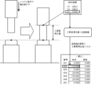
データ抽出部5は、工具形状補正量の設定(変化)を検出する(ステップS9)。図10の例では、工具番号「002」の工具長補正量が「110.000」に設定される。工具長補正量は、「0.000」から「110.000」に変化するが、この変化は映像から判断できるので表示データとして抽出されない。
映像生成部6は、映像取得部1が取得した映像と、データ抽出部5が抽出したデータとを、時刻でマージし、機械の状態変化をデータで表示する画面を作成する。
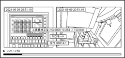
図11及び図12を参照して表示画面の変化を説明する。図11は従来の映像生成装置100で生成した映像の例であり、図12は本開示を適用した映像生成装置100で生成した映像の例である。
図11及び図12を参照して表示画面の変化を説明する。図11は従来の映像生成装置100で生成した映像の例であり、図12は本開示を適用した映像生成装置100で生成した映像の例である。
従来の映像(図11)では、工具オフセットが設定された時点の映像に対し、「工具長補正量 HG 0005 10.264->102.640」、「MDIモード」、「操作G0014.1」というデータが表示される。
本開示を適用した映像(図12)では、工具長補正量の変化は表示しない。そのため、「MDIモード」、「操作G0014.1」のみが表示される。表示されるデータの数が少ないため、産業機械の動作及び表示画面がテキストで隠れることがない。
映像の解析を行うとき、全てのデータを画面に表示すると、データの数が多くなり、画面が煩雑になる。本開示では、映像が撮影された時点での、データの抽出条件を設定し、抽出条件に適合するデータを表示データとして抽出する。表示データはタイムスタンプを付して保存する。映像生成装置は、時刻をキーとして、映像とデータをマージし、データを映像に重ねて表示する。
本開示の映像生成装置によれば、表示データの数が抑えられるので、視認性のよい表示画面が提供できる。
本開示の映像生成装置によれば、表示データの数が抑えられるので、視認性のよい表示画面が提供できる。
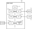
以下、本開示を適用した映像生成装置のハードウェア構成について説明する。図13は、映像生成装置100のハードウェア構成図である。映像生成装置100は、図1に示すように、映像生成装置100を全体的に制御するCPU111、プログラムやデータを記録するROM112、一時的にデータを展開するためのRAM113を備え、CPU111はバスを介してROM112に記録されたシステムプログラムを読み出し、システムプログラムに従って映像生成装置100の全体を制御する。
不揮発性メモリ114は、例えば、図示しないバッテリでバックアップされるなどして、映像生成装置100の電源がオフされても記憶状態が保持される。不揮発性メモリ114には、インタフェース115、118、119を介して外部機器から読み込まれたプログラムや入力部30を介して入力されたユーザ操作などの各種データが記憶される。
100 映像生成装置
1 映像取得部
2 データ取得部
3 画面判別部
4 抽出条件記憶部
5 データ抽出部
6 映像生成部
111 CPU
113 RAM
114 不揮発性メモリ
1 映像取得部
2 データ取得部
3 画面判別部
4 抽出条件記憶部
5 データ抽出部
6 映像生成部
111 CPU
113 RAM
114 不揮発性メモリ
Claims (9)
- 産業機械の表示画面を含む、前記産業機械の映像を取得する映像取得部と、
前記産業機械の機械状態を示すデータを取得するデータ取得部と、
前記表示画面の種類を判別する画面判別部と、
前記表示画面の種類と、前記産業機械の状態情報を元に、前記データの一部を抽出するデータ抽出部と、
前記データ抽出部が抽出したデータと、前記データ取得部が取得した映像とを同時に表示する映像を生成する映像生成部と、
を備える映像生成装置。 - 前記映像取得部が取得した映像には前記映像を撮影した時刻が含まれ、
前記データ取得部が取得したデータが出力された時刻が付加されており、
前記映像生成部は、前記時刻をキーとして、映像とデータをマージさせる、請求項1記載の映像生成装置。 - 前記画面判別部は、前記映像取得部から取得した表示画面に基づき、前記表示画面の種類を判別する、請求項1記載の映像生成装置。
- 前記画面判別部は、前記データ取得部が取得したデータに含まれる、前記産業機械の動作モード又は操作信号の少なくとも一方に基づき、前記表示画面の種類を判別する、請求項1記載の映像生成装置。
- 前記データ抽出部は、前記画面判別部が判定した表示画面が提供する情報と重複するデータを除外して抽出する、請求項1記載の映像生成装置。
- 前記データ抽出部は、前記データ取得部が取得したデータに含まれる、前記産業機械の動作モード又は信号の少なくとも一方に基づき、データを抽出する、請求項1記載の映像生成装置。
- 前記データ抽出部は、前記データ取得部が取得したデータの値が変化すると、変化したデータを抽出するか否かを判断する、請求項1記載の映像生成装置。
- 前記データ抽出部の抽出条件には、データの値の変化に関わらず常時抽出されるデータが含まれる、請求項7記載の映像生成装置。
- 1つ又は複数のプロセッサが実行することにより、
産業機械の表示画面を含む、前記産業機械の映像を取得し、
前記産業機械の機械状態を示すデータを取得し、
前記表示画面の種類を判別し、
前記表示画面の種類と、前記産業機械の状態情報を元に、映像の生成に用いるデータを抽出し、
前記抽出したデータと、前記取得した映像とを同時に表示する映像を作成する、
前記プロセッサが読み取り可能な命令を記憶する記憶媒体。
Priority Applications (2)
| Application Number | Priority Date | Filing Date | Title |
|---|---|---|---|
| PCT/JP2022/020223 WO2023218640A1 (ja) | 2022-05-13 | 2022-05-13 | 映像生成装置、及びコンピュータが読み取り可能な記憶媒体 |
| JP2024520213A JP7827845B2 (ja) | 2022-05-13 | 2022-05-13 | 映像生成装置、及びコンピュータが読み取り可能な記憶媒体 |
Applications Claiming Priority (1)
| Application Number | Priority Date | Filing Date | Title |
|---|---|---|---|
| PCT/JP2022/020223 WO2023218640A1 (ja) | 2022-05-13 | 2022-05-13 | 映像生成装置、及びコンピュータが読み取り可能な記憶媒体 |
Publications (1)
| Publication Number | Publication Date |
|---|---|
| WO2023218640A1 true WO2023218640A1 (ja) | 2023-11-16 |
Family
ID=88730123
Family Applications (1)
| Application Number | Title | Priority Date | Filing Date |
|---|---|---|---|
| PCT/JP2022/020223 Ceased WO2023218640A1 (ja) | 2022-05-13 | 2022-05-13 | 映像生成装置、及びコンピュータが読み取り可能な記憶媒体 |
Country Status (2)
| Country | Link |
|---|---|
| JP (1) | JP7827845B2 (ja) |
| WO (1) | WO2023218640A1 (ja) |
Citations (4)
| Publication number | Priority date | Publication date | Assignee | Title |
|---|---|---|---|---|
| JP2005018298A (ja) * | 2003-06-25 | 2005-01-20 | Hitachi Ltd | 監視,操作方法および表示装置 |
| JP2005056098A (ja) * | 2003-08-04 | 2005-03-03 | Digital Electronics Corp | 表示装置 |
| JP2017167867A (ja) * | 2016-03-17 | 2017-09-21 | 株式会社ジェイテクト | 工作機械用管理システム |
| JP2020179487A (ja) * | 2019-04-26 | 2020-11-05 | 株式会社ディスコ | 加工装置 |
-
2022
- 2022-05-13 JP JP2024520213A patent/JP7827845B2/ja active Active
- 2022-05-13 WO PCT/JP2022/020223 patent/WO2023218640A1/ja not_active Ceased
Patent Citations (4)
| Publication number | Priority date | Publication date | Assignee | Title |
|---|---|---|---|---|
| JP2005018298A (ja) * | 2003-06-25 | 2005-01-20 | Hitachi Ltd | 監視,操作方法および表示装置 |
| JP2005056098A (ja) * | 2003-08-04 | 2005-03-03 | Digital Electronics Corp | 表示装置 |
| JP2017167867A (ja) * | 2016-03-17 | 2017-09-21 | 株式会社ジェイテクト | 工作機械用管理システム |
| JP2020179487A (ja) * | 2019-04-26 | 2020-11-05 | 株式会社ディスコ | 加工装置 |
Also Published As
| Publication number | Publication date |
|---|---|
| JPWO2023218640A1 (ja) | 2023-11-16 |
| JP7827845B2 (ja) | 2026-03-10 |
Similar Documents
| Publication | Publication Date | Title |
|---|---|---|
| JP6432494B2 (ja) | 監視装置、監視システム、監視プログラムおよび記録媒体 | |
| CN105992976B (zh) | 加工信息管理装置以及工具路径生成装置 | |
| JP6377167B2 (ja) | 工作機械の制御装置 | |
| EP3699709B1 (en) | Servo motor adjusting device and servo motor adjusting method | |
| US20190266296A1 (en) | Machining simulation device of machine tool | |
| TWI559107B (zh) | 監視控制裝置 | |
| KR20190105518A (ko) | 로봇 제어 장치, 기록의 작성 방법 및 프로그램 | |
| JP2019160250A (ja) | 情報処理装置、情報処理方法、プログラム、および機械装置 | |
| JP7668669B2 (ja) | 分析装置、分析システム、およびその制御方法 | |
| WO2023218640A1 (ja) | 映像生成装置、及びコンピュータが読み取り可能な記憶媒体 | |
| JP2009000373A (ja) | ミシンの生産管理装置 | |
| JP6705768B2 (ja) | 情報処理装置 | |
| KR102902787B1 (ko) | 감시 데이터 처리 장치 | |
| JP7712373B2 (ja) | 教示装置及びロボットシステム | |
| CN117279737B (zh) | 运行状况显示装置以及计算机可读存储介质 | |
| US20210350296A1 (en) | Productivity improvement support system and productivity improvement support method | |
| WO2020065854A1 (ja) | ワーク位置検出方法及び工作機械 | |
| WO2023218651A1 (ja) | 映像関連情報決定装置、及びコンピュータが読み取り可能な記憶媒体 | |
| US20250301206A1 (en) | Video generation device and computer-readable storage medium | |
| JP7646098B1 (ja) | 画面データ作成プログラム、画面データ作成装置、プログラマブル表示システム、プログラマブル表示器及び画面データ作成方法 | |
| WO2023218653A1 (ja) | 映像管理装置、及びコンピュータが読み取り可能な記憶媒体 | |
| EP1746474A1 (en) | Numerical controller with integrated CNC frame and application frame display | |
| JP7328473B1 (ja) | 制御装置、産業機械のシステム、実行履歴データ表示方法、及びプログラム | |
| WO2023139772A9 (ja) | 情報生成装置、およびコンピュータ読み取り可能な記憶媒体 | |
| WO2024062541A9 (ja) | 画像生成システム及びコンピュータ読み取り可能な記録媒体 |
Legal Events
| Date | Code | Title | Description |
|---|---|---|---|
| 121 | Ep: the epo has been informed by wipo that ep was designated in this application |
Ref document number: 22941717 Country of ref document: EP Kind code of ref document: A1 |
|
| ENP | Entry into the national phase |
Ref document number: 2024520213 Country of ref document: JP Kind code of ref document: A |
|
| NENP | Non-entry into the national phase |
Ref country code: DE |
|
| 122 | Ep: pct application non-entry in european phase |
Ref document number: 22941717 Country of ref document: EP Kind code of ref document: A1 |