WO2023218630A1 - 照明装置及び移動撮像システム - Google Patents
照明装置及び移動撮像システム Download PDFInfo
- Publication number
- WO2023218630A1 WO2023218630A1 PCT/JP2022/020181 JP2022020181W WO2023218630A1 WO 2023218630 A1 WO2023218630 A1 WO 2023218630A1 JP 2022020181 W JP2022020181 W JP 2022020181W WO 2023218630 A1 WO2023218630 A1 WO 2023218630A1
- Authority
- WO
- WIPO (PCT)
- Prior art keywords
- light sources
- light
- lighting device
- plane
- light source
- Prior art date
- Legal status (The legal status is an assumption and is not a legal conclusion. Google has not performed a legal analysis and makes no representation as to the accuracy of the status listed.)
- Ceased
Links
Images





Classifications
-
- F—MECHANICAL ENGINEERING; LIGHTING; HEATING; WEAPONS; BLASTING
- F21—LIGHTING
- F21S—NON-PORTABLE LIGHTING DEVICES; SYSTEMS THEREOF; VEHICLE LIGHTING DEVICES SPECIALLY ADAPTED FOR VEHICLE EXTERIORS
- F21S2/00—Systems of lighting devices, not provided for in main groups F21S4/00 - F21S10/00 or F21S19/00, e.g. of modular construction
-
- F—MECHANICAL ENGINEERING; LIGHTING; HEATING; WEAPONS; BLASTING
- F21—LIGHTING
- F21V—FUNCTIONAL FEATURES OR DETAILS OF LIGHTING DEVICES OR SYSTEMS THEREOF; STRUCTURAL COMBINATIONS OF LIGHTING DEVICES WITH OTHER ARTICLES, NOT OTHERWISE PROVIDED FOR
- F21V5/00—Refractors for light sources
-
- F—MECHANICAL ENGINEERING; LIGHTING; HEATING; WEAPONS; BLASTING
- F21—LIGHTING
- F21W—INDEXING SCHEME ASSOCIATED WITH SUBCLASSES F21K, F21L, F21S and F21V, RELATING TO USES OR APPLICATIONS OF LIGHTING DEVICES OR SYSTEMS
- F21W2131/00—Use or application of lighting devices or systems not provided for in codes F21W2102/00-F21W2121/00
- F21W2131/10—Outdoor lighting
- F21W2131/101—Outdoor lighting of tunnels or the like, e.g. under bridges
-
- F—MECHANICAL ENGINEERING; LIGHTING; HEATING; WEAPONS; BLASTING
- F21—LIGHTING
- F21W—INDEXING SCHEME ASSOCIATED WITH SUBCLASSES F21K, F21L, F21S and F21V, RELATING TO USES OR APPLICATIONS OF LIGHTING DEVICES OR SYSTEMS
- F21W2131/00—Use or application of lighting devices or systems not provided for in codes F21W2102/00-F21W2121/00
- F21W2131/40—Lighting for industrial, commercial, recreational or military use
- F21W2131/411—Lighting for industrial, commercial, recreational or military use for inspection of the interior of hollow structures, e.g. vessels, tubes
Definitions
- the present disclosure relates to a lighting device that illuminates a wall surface of a structure, and a mobile imaging system equipped with the lighting device.
- Patent Document 1 discloses a lighting unit that is mounted on a vehicle or the like and illuminates the wall surface of a structure such as a tunnel.
- the lighting unit has six light sources arranged in a plane intersecting the traveling direction of the vehicle, and a lens is individually arranged on the emission side of each light source.
- the lighting unit disclosed in Patent Document 1 requires the same number of lenses as light sources, which increases the size of the lighting unit.
- the present disclosure has been made in view of the problems of the prior art, and aims to provide a lighting device that is small and has a simple configuration and is capable of illuminating a wide range.
- the lighting device of the present disclosure includes a light source section in which a plurality of light sources are arranged on the same plane so that the optical axes of the plurality of light sources are radial, and light emitted from the plurality of light sources enters the light source section, and the light emitted from the plurality of light sources enters the light source section. and a common lens that emits light toward the target surface.
- the illumination device of the present disclosure by using a common lens and a plurality of light sources arranged on the same plane so that the optical axes are radial, a wide area can be uniformly illuminated with a small and simple configuration. can do.
- FIG. 1 is a side view schematically showing a mobile imaging system having an illumination device according to a first embodiment
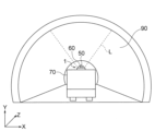
- FIG. 1 is a rear view schematically showing a mobile imaging system having an illumination device according to Embodiment 1.
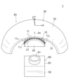
- FIG. 1 is a perspective view showing an illumination device and an imaging device according to a first embodiment
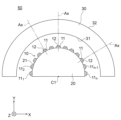
- FIG. 1 is a diagram showing a configuration of a lighting device according to a first embodiment
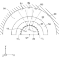
- FIG. 3 is a diagram showing an optical path in the XY plane of light emitted from the light source of the lighting device according to the first embodiment.
- FIG. 3 is a diagram showing an optical path of light emitted from a light source of the lighting device according to the first embodiment in the YZ plane.
- FIG. 2 is a block diagram showing a control system of the mobile imaging system according to the first embodiment.
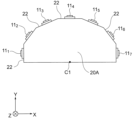
- 7 is a diagram showing a light source and a substrate of a lighting device according to a second embodiment.
- FIG. FIG. 7 is a diagram illustrating a configuration example of a lighting device according to a third embodiment. 7 is a diagram illustrating another configuration example of the lighting device according to Embodiment 3.
- the traveling direction of a moving body such as a vehicle is assumed to be the Z-axis direction.
- the moving direction of the moving body when moving forward is defined as the +Z-axis direction, and the opposite direction is defined as the -Z-axis direction.
- the left-right direction of the moving body is the X-axis direction.
- the right side when facing the front of the moving body, that is, the +Z-axis direction, is the +X-axis direction, and the left side when facing the front of the moving body is the ⁇ X-axis direction.
- the ZX plane is a plane parallel to the road surface.
- the vertical direction of the moving body is the Y-axis direction.
- the upper side is the +Y-axis direction, and the lower side is the -Y-axis direction.
- “Upper side” is toward the sky, and “lower side” is toward the ground (ie, road surface).
- FIG. 1 is a side view schematically showing a mobile imaging system 1 including a lighting device 50 according to the first embodiment.
- FIG. 2 is a diagram of the mobile imaging system 1 viewed from the ⁇ Z-axis direction, that is, a rear view.
- the mobile imaging system 1 including the illumination device 50 of the first embodiment is attached to a moving body 70.
- the moving object 70 is, for example, a vehicle such as a car that runs on a road surface.
- the moving body 70 may be a cart moved by a person, a track car running on a track, or the like.
- the mobile imaging system 1 images the wall surface of a structure.
- the wall surface of the structure is, for example, a wall surface 90 of a tunnel.
- the cross-sectional shape of the tunnel in the XY plane is generally semicircular. Below, an example will be described in which the mobile imaging system 1 images the wall surface 90 while the moving body 70 moves on the road surface in the +Z-axis direction.
- the mobile imaging system 1 includes an illumination device 50 that illuminates the wall surface 90 as shown by the broken line L, and an imaging device 60 that images the wall surface 90 illuminated by the illumination device 50.
- the illumination device 50 and the imaging device 60 are attached to a mounting portion 71 provided on the moving body 70.
- the attachment part 71 is attached to the upper part or rear part of the moving body 70, for example.
- FIG. 3 is a perspective view showing the illumination device 50 and imaging device 60 of the mobile imaging system 1.
- the illumination device 50 is arranged in front of the imaging device 60 (in the +Z-axis direction).
- the arrangement is not limited to this, as long as the illumination device 50 can illuminate the imaging range of the imaging device 60.
- the imaging device 60 includes a line sensor 62 having a plurality of light-receiving elements, a lens 61 that focuses an image of a wall surface 90 (FIG. 1) that is an object onto the light-receiving element, and a housing 63 that accommodates them.
- the line sensor 62 has a plurality of light receiving elements arranged in a line.
- the arrangement direction of the light receiving elements is the X-axis direction here, it is not limited to the X-axis direction and may be, for example, the Y-axis direction.
- the light receiving element is, for example, a CCD (Charge Coupling Device).
- the line sensor 62 is used instead of the line sensor.
- the area sensor is a two-dimensional array of light receiving elements.
- FIG. 4 is a diagram of the illumination device 50 viewed from the ⁇ Z-axis direction, that is, a rear view.
- the lighting device 50 includes a light source unit 10 including n light sources 11 arranged in the X-axis direction, a substrate 20 as a support supporting the n light sources 11, and light emitted from the n light sources 11.
- the lens 30 is provided with a lens 30 through which the light enters and irradiates the wall surface 90 (FIG. 1) with the light.
- n is an integer of 2 or more.
- the n light sources 11 are arranged in a circumferential direction centered on the central axis C1 in the Z-axis direction. Further, these n light sources 11 are arranged on a plane perpendicular to the Z-axis (that is, a plane PL shown in FIG. 6, which will be described later).
- the n light sources 11 are written as light source 11 1 , light source 11 2 , ... light source 11 n in order from one end in the arrangement direction to the other end, here from the end in the -X axis direction to the end in the +X axis direction. There is also.
- a light source group including n light sources 11 is referred to as a light source section 10.
- the light source 11 is preferably a semiconductor light source, for example, and particularly a light emitting diode (LED). Alternatively, it may be a laser diode (LD).
- LED light emitting diode
- LD laser diode
- the substrate 20 has an arrangement surface 21 on which n light sources 11 are arranged. Each light source 11 is fixed to the arrangement surface 21 by adhesive or the like.
- the cross-sectional shape of the substrate 20 in the XY plane is convex in the Y-axis direction. More specifically, the cross-sectional shape of the arrangement surface 21 in the XY plane is preferably an arc shape centered on the central axis C1, which is a virtual straight line in the Z-axis direction, and is particularly preferably a semicircle shape.
- the substrate 20 is not limited to such a shape, and may have a polygonal cross-sectional shape in the XY plane, as shown in FIG. 8, which will be described later.
- the direction of the optical axis Ax of each light source 11 arranged on the arrangement surface 21 of the substrate 20 is a radial direction centered on the above-mentioned central axis C1.
- the optical axes Ax of the n light sources 11 are radial.
- the optical axis Ax is a normal line passing through the center of the light emitting surface 12 of the light source 11.
- the lens 30 has an entrance surface 31 into which light from the n light sources 11 enters, and an exit surface 32 through which the light incident from the entrance surface 31 exits. Both the entrance surface 31 and the exit surface 32 extend in the XY plane in an arc shape centered on the central axis C1, and more preferably in a semicircle shape. That is, the entrance surface 31 and the exit surface 32 of the lens 30 are concentric circles in the XY plane.
- FIG. 5 is a diagram schematically showing the optical path of the light emitted from the light source 11 in the XY plane.
- the entrance surface 31 and the exit surface 32 are arranged concentrically around the central axis C1 in the XY plane.
- the n light sources 11 are also arranged along an arc (more preferably a semicircle) centered on the central axis C1.
- the optical axis Ax of each light source 11 coincides with the normal direction of the entrance surface 31 of the lens 30 and also coincides with the normal direction of the exit surface 32 in the XY plane. That is, the light emitted from the light source 11 is emitted without being focused in the X-axis direction, and is irradiated onto the wall surface 90. That is, the lens 30 has no power (refractive power) in the X-axis direction.
- three adjacent light sources 11 are assumed to be light sources 11 k-1 , 11 k , and 11 k+1 .
- the light emitted from the light sources 11 k-1 , 11 k , 11 k+1 passes through the entrance surface 31 and the exit surface 32 of the lens 30, and is irradiated onto the irradiation areas B1, B2, and B3 of the wall surface 90. It is desirable that the irradiation areas B1, B2, and B3 on the wall surface 90 slightly overlap each other without leaving any gaps.
- FIG. 5 shows the optical paths of the light emitted from the three light sources 11 k ⁇ 1 , 11 k , and 11 k+1 , the wall surface 90 is irradiated with the light emitted from all n light sources 11 .
- the n light sources 11 and one lens 30 can uniformly illuminate the wall surface 90, which is the target surface, over a range of, for example, 180 degrees.
- FIG. 6 is a diagram schematically showing the optical path of the light emitted from the light source 11 in the YZ plane.
- the n light sources 11 are located on the plane PL perpendicular to the Z-axis. Note that n light sources 11 being located on plane PL means that the center of each light emitting surface 12 of n light sources 11 is located on plane PL. Each optical axis Ax of the n light sources 11 is on the plane PL.
- the center of the entrance surface 31 of the lens 30 in the Z-axis direction and the center of the exit surface 32 in the Z-axis direction are on the plane PL.
- the center of the incident surface 31 in the Z-axis direction and the center of the exit surface 32 in the Z-axis direction coincide with the centers of the n light sources 11 .
- the curvatures of the entrance surface 31 and the exit surface 32 of the lens 30 are set so that the combined power of the entrance surface 31 and the exit surface 32 is larger in the Z-axis direction (FIG. 6) than in the X-axis direction (FIG. 5). ing.
- the lens 30 has no power in the X-axis direction as described above, and has positive power in the Z-axis direction.
- the power of the lens 30 in the direction perpendicular to the plane PL is greater than the power in the direction in which the light sources 11 are arranged (ie, the X-axis direction).
- the lens 30 has no power in the direction in which the light sources 11 are arranged (ie, the X-axis direction), but has positive power in the direction perpendicular to the plane PL (ie, the Z-axis direction).
- the moving body 70 moves in the Z-axis direction, it is desirable to widen the illumination range in the XY plane perpendicular to the Z-axis, but the illumination range may be narrower in the YZ plane that includes the moving direction of the moving body 70. .
- the entrance surface 31 and the exit surface 32 of the lens 30 have positive power in the Z-axis direction, the light emitted from each light source 11 is condensed in the Z-axis direction, and illumination is performed with a smaller amount of emitted light. It is possible to obtain high illuminance in the range.
- the combined focal point of the entrance surface 31 and the exit surface 32 be near the light source 11.
- the light emitted from each light source 11 is emitted from the exit surface 32 of the lens 30 as approximately parallel light.
- the illuminance in the illumination range of the wall surface 90 can be further increased.
- the combined focal point of the entrance surface 31 and the exit surface 32 may be shifted from the light source 11 in the Y-axis direction, thereby widening the light flux emitted from the lens 30. In this way, the illumination range on the wall surface 90 can be expanded in the Z-axis direction.
- the entrance surface 31 is linear, and the exit surface 32 is curved to be convex in the +Y-axis direction.
- the light emitted from each light source 11 can be condensed in the YZ plane,
- the shapes of the entrance surface 31 and the exit surface 32 are not limited to the above shapes.
- n light sources 11 are arranged on the same plane so that their respective optical axes Ax are radial, a wide range of the wall surface 90 can be evenly illuminated. Furthermore, since a common lens 30 is provided for the n light sources 11, the configuration of the illumination device 50 is simpler and more compact than in the case where a lens is provided for each light source 11. Become.
- the present invention is not limited to such a case. That is, it is sufficient that the power in the X-axis direction, which is the sum of the entrance surface 31 and the exit surface 32 of the lens 30, is smaller than the power in the Z-axis direction.
- the n light sources 11 are arranged along an arc (more preferably a semicircle) centered on the central axis C1, and the entrance surface 31 and the exit surface of the lens 30 are arranged in a circle centered on the central axis C1.
- the central axis of the arc in which the light sources 11 are arranged does not necessarily coincide with the central axis of the arc that is the shape of the entrance surface 31 and the exit surface 32. It doesn't have to be.
- the central axis C1 may be inclined with respect to the Z-axis direction. That is, the plane PL only needs to intersect with the traveling direction of the moving body 70.
- FIG. 7 is a block diagram showing a control system of the mobile imaging system 1 according to the first embodiment.
- the mobile imaging system 1 includes a control section 80, a data storage section 81, a time acquisition section 85, a speed acquisition section 86, an image processing section 87, a light source 11, and a line sensor 62.
- the control unit 80 is, for example, a CPU (Central Processing Unit), and sends control signals to the line sensor 62, the n light sources 11, the time acquisition unit 85, and the speed acquisition unit 86.
- the control signals include an imaging control signal that controls the operation of the line sensor 62, a lighting control signal that controls the operation of each light source 11, and a data acquisition control signal that controls the operation of the time acquisition section 85 and speed acquisition section 86. There is.
- the line sensor 62 performs an imaging operation based on an imaging control signal from the control unit 80.
- the n light sources 11 are turned on and off by an imaging control signal from the control unit 80. Note that the n light sources 11 may be turned on and off all at once, or may be turned on and off individually.
- the time acquisition unit 85 acquires the time when the line sensor 62 takes an image.
- the speed acquisition unit 86 acquires the speed of the moving object 70 when the image of the line sensor 62 is taken.
- the data storage section 81 includes an image data storage section 82, a speed data storage section 83, and a time data storage section 84.
- the image data storage unit 82 stores the image captured by the line sensor 62.
- the time data storage unit 84 stores the time data acquired by the time acquisition unit 85 in association with the image.
- the speed data storage unit 83 stores the speed data acquired by the speed acquisition unit 86 in association with the image.
- the image processing unit 87 combines the image data stored in the image data storage unit 82 and generates one composite image.
- the image generated by the image processing unit 87 is sent to the outside and used to inspect the tunnel wall 90 for abnormalities.
- the image processing section 87 may be provided in the moving body 70 or may be provided externally.
- the light source section 10 has n light sources 11 arranged on the same plane so that the respective optical axes Ax are radial, and the light emitted from these light sources 11 is A common lens 30 that enters the light and emits the light toward the wall surface 90 is provided. Since the n light sources 11 are arranged in this way, a wide range of the wall surface 90 can be evenly illuminated. In addition, since the common lens 30 is provided for the n light sources 11, the number of parts of the lighting device 50 is reduced compared to the case where the same number of lenses as the light sources 11 are provided, and the configuration is simplified. .
- the plurality of light sources 11 are arranged along an arc (more preferably a semicircle) centered on the central axis C1, which is a virtual straight line in the Z-axis direction, and the entrance surface 31 and exit surface 32 of the lens 30 are Since both extend in an arc shape (more preferably a semicircle shape) centered on the central axis C1, the light emitted from the lens 30 is irradiated over a wide range in the X-axis direction, and the wall surface 90 is Can illuminate a wide area.
- arc more preferably a semicircle
- the lens 30 has a larger power in the Z-axis direction than in the X-axis direction, the light emitted from the lens 30 is irradiated over a wide range in the X-axis direction, and is focused in the Z-axis direction. be able to. That is, high illuminance can be obtained over a wide range of the wall surface 90.
- each light source 11 is a light emitting diode, the light emitting efficiency is high, and the power consumption of the lighting device 50 can be reduced.
- FIG. 8 is a diagram showing a substrate 20A and a light source 11 as a support according to the second embodiment.
- the substrate 20 of the first embodiment described above had a semicircular cross-sectional shape in the XY plane.
- the substrate 20A of the second embodiment has a polygonal cross-sectional shape in the XY plane.
- the substrate 20A has n arrangement surfaces 22 on which n light sources 11 are arranged.
- the arrangement surface 22 is a flat surface, and one light source 11 is arranged on one arrangement surface 22.
- the arrangement surfaces 22 are, for example, arranged at equal intervals in the circumferential direction around the central axis C1. Although FIG. 8 shows the case where n is 7, n may be 2 or more.
- the substrate 20A has a polygonal shape, and each light source 11 is attached to a flat placement surface 22 by adhesive or the like. Therefore, the light source 11 can be easily mounted at the target position, and the manufacturing process of the lighting device 50 can be simplified.
- FIG. 9 is a diagram of the illumination device 50A of the third embodiment viewed from the ⁇ Z-axis direction.
- the lighting device 50A of the third embodiment has a configuration suitable for a case where the distance from the light source 11 to the wall surface 90 is not constant.
- the height of the tunnel is less than 1/2 of the width of the tunnel.
- the cross-sectional shape of the tunnel in the XY plane is a horizontally long ellipse. Therefore, the distance R1 in the optical axis Ax direction from the light source 11 at the center in the X-axis direction of the light source unit 10 to the center (that is, the top) of the wall surface 90 is the distance R1 from the light source 11 at the end in the X-axis direction to the side part of the wall surface 90. It is shorter than the distance R2 in the optical axis Ax direction.
- the illuminance will be high at the center of the wall surface 90, while the illuminance will be low at the side portions of the wall surface 90.
- uneven illuminance occurs such that the central portion of the wall surface 90 is brightly illuminated and the side portions of the wall surface 90 are darkly illuminated.
- the arrangement interval of the light sources 11 arranged in the first region E1 where the distance to the wall surface 90 is short is different from that in the second region where the distance to the wall surface 90 is long.
- the interval is set wider than the interval between the light sources 11 arranged at E2.
- the light sources 11 are arranged densely compared to the first region E1 where the distance to the wall surface 90 is short.
- the first region E1 is a central region in the X-axis direction
- the second region E2 is an end region in the X-axis direction.
- the light sources 11 are arranged in this way, even if the cross-sectional shape of the wall surface 90 is horizontally elongated, the illuminance of the entire wall surface 90 can be made uniform. That is, the wall surface 90 can be uniformly illuminated.
- the first area E1 includes three light sources 11, and the second area E2 also includes three light sources 11, but the number of light sources 11 included in each area E1, E2 is 1. It suffices if there are more than one.
- the cross-sectional shape of the wall surface 90 may be vertically long as shown in FIG.
- the arrangement interval of the light sources 11 arranged in the first region E1, which is close to the wall surface 90, is the same as that of the light sources 11 arranged in the second region E2, which is far from the wall surface 90.
- the wall surface 90 can be uniformly illuminated by making the arrangement interval wider than the arrangement interval.
- the first region E1 is an end region in the X-axis direction
- the second region E2 is a central region in the X-axis direction.
- the arrangement interval of the light sources 11 was made different between the first region E1, which is close to the wall surface 90, and the second region E2, which is far from the wall surface 90, Additionally, the driving current of the light source 11 may be varied.
- the N light sources 11 are controlled by the control unit 80.
- the control unit 80 turns on the N light sources 11, the drive current supplied to each light source 11 in the first region E1 may be smaller than the drive current supplied to each light source 11 in the second region E2. .
- the amount of light emitted from the light source 11 changes depending on the drive current.
- the amount of light emitted from each light source 11 in the first region E1 becomes smaller than the amount of light emitted from each light source 11 in the second region E2.
- the amount of light emitted from each light source 11 in the second region E2 is larger than the amount of light emitted from each light source 11 in the first region E1.
- the light source 11 arranged on the left side (-X axis side) of the central axis C1 is slightly close to the wall surface 90 and on the right side (+X axis side).
- the light source 11 arranged on the side) is slightly far from the wall surface 90.
- the left side of the central axis C1 is set as the first area E1
- the right side is set as the second area E2
- the arrangement interval of the light sources 11 is narrower in the second area E2 than in the first area E1
- the drive current may be increased.
- the light source section 10 may be divided into three or more regions, and the arrangement interval of the light sources 11, the drive current, or both may be varied depending on the distance to the wall surface 90.
- Embodiments 1 to 3 have been described, the present disclosure is not limited to these embodiments. Further, Embodiments 1 to 3 may be combined as appropriate.
- the present disclosure is applied to a lighting device that illuminates a target surface. Further, the present disclosure may be applied to a device that emits a low beam or a high beam in a headlight device for a motorcycle, a tricycle, a four-wheel vehicle, or the like.
- Mobile imaging system 10. Light source section, 11. Light source, 12. Output surface, 20, 20A substrate (support body), 21, 22. Arrangement surface, 30. Lens, 31. Incident surface, 32. Output surface, 50. Illumination device. 60 Imaging device, 61 Lens, 62 Line sensor, 70 Moving body, 80 Control unit, 90 Wall surface.
Landscapes
- Engineering & Computer Science (AREA)
- General Engineering & Computer Science (AREA)
- Investigating Materials By The Use Of Optical Means Adapted For Particular Applications (AREA)
- Fastening Of Light Sources Or Lamp Holders (AREA)
- Studio Devices (AREA)
- Non-Portable Lighting Devices Or Systems Thereof (AREA)
Abstract
照明装置(1)は、複数の光源(11)を、当該複数の光源(11)の光軸(Ax)が放射状となるように同一平面上に配列した光源部(10)と、複数の光源(11)から出射された光が入射し、当該光を対象面(90)に向けて出射する共通のレンズ(30)とを有する。
Description
本開示は、構造物の壁面等を照明する照明装置と、照明装置を備えた移動撮像システムに関する。
トンネル等の構造物の検査のため、車両に搭載した撮像装置で構造物の壁面を撮像する技術が開発されている。壁面を撮像する際には、壁面の撮影範囲を照明する必要がある。
例えば、特許文献1には、車両等に搭載され、トンネル等の構造体の壁面を照明する照明ユニットが開示されている。照明ユニットは、車両の走行方向と交差する面内に配置された6つの光源を有し、各光源の出射側には個別にレンズが配置されている。
しかしながら、特許文献1に開示された照明ユニットでは、光源と同数のレンズが必要となるため、照明ユニットが大型化する。
また、各光源の照明範囲の重なり部分を少なくするため、隣り合うレンズの光軸の位置を車両の走行方向にずらす必要があり、照明ユニットの構成が複雑化する。
本開示は、従来技術の課題に鑑みてなされたものであり、小型且つ簡単な構成で、広い範囲を照明可能な照明装置を提供することを目的とする。
本開示の照明装置は、複数の光源を、当該複数の光源の光軸が放射状となるように同一平面上に配列した光源部と、複数の光源から出射された光が入射し、当該光を対象面に向けて出射する共通のレンズとを備える。
本開示の照明装置によれば、光軸が放射状となるように同一平面上に配列された複数の光源と共通のレンズとを用いることにより、小型且つ簡単な構成で、広い範囲を均等に照明することができる。
以下に、実施の形態に係る照明装置を、図面を参照しながら説明する。以下の実施の形態は例にすぎず、実施の形態を適宜組み合わせること及び各実施の形態を適宜変更することが可能である。
以下の実施の形態の説明では、説明を容易にするためにXYZ座標系の座標軸及び座標平面を用いる。車両等の移動体の進行方向をZ軸方向とする。移動体の前進時の進行方向を+Z軸方向とし、その反対の方向を-Z軸方向とする。
また、移動体の左右方向をX軸方向とする。移動体の前方すなわち+Z軸方向を向いたときの右側を+X軸方向とし、移動体の前方を向いたときの左側を-X軸方向とする。ZX平面は、路面に平行な面である。
また、移動体の上下方向をY軸方向とする。上側を+Y軸方向とし、下側を-Y軸方向とする。「上側」とは空の方向であり、「下側」とは地面(すなわち、路面)の方向である。
《実施の形態1》
〈移動撮像システム〉
図1は、実施の形態1に係る照明装置50を含む移動撮像システム1を概略的に示す側面図である。図2は、この移動撮像システム1を-Z軸方向から見た図、すなわち背面図である。
〈移動撮像システム〉
図1は、実施の形態1に係る照明装置50を含む移動撮像システム1を概略的に示す側面図である。図2は、この移動撮像システム1を-Z軸方向から見た図、すなわち背面図である。
実施の形態1の照明装置50を含む移動撮像システム1は、移動体70に取り付けられている。移動体70は、例えば、路面を走行する自動車等の車両である。但し、移動体70は、人が移動させる台車、あるいは軌道上を走行する軌道車等であってもよい。
移動撮像システム1は、構造物の壁面を撮像する。構造物の壁面は、例えばトンネルの壁面90である。トンネルのXY平面における断面形状は、一般に、概ね半円形である。以下では、移動体70が路面上を+Z軸方向に移動しながら、移動撮像システム1が壁面90を撮像する例について説明する。
移動撮像システム1は、壁面90を破線Lで示すように照明する照明装置50と、照明装置50によって照明された壁面90を撮像する撮像装置60とを有する。照明装置50及び撮像装置60は、移動体70に設けられた取付け部71に取り付けられている。なお、取付け部71は、例えば、移動体70の上部、あるいは後部に取り付けられる。
図3は、移動撮像システム1の照明装置50及び撮像装置60を示す斜視図である。ここでは、照明装置50が撮像装置60の前方(+Z軸方向)に配置されている。但し、このような配置に限らず、照明装置50が撮像装置60の撮像範囲を照明することができればよい。
撮像装置60は、複数の受光素子を有するラインセンサ62と、対象物である壁面90(図1)の像を受光素子に集光させるレンズ61と、これらを収容するハウジング63とを有する。
ラインセンサ62は、複数の受光素子を一列に配列したものである。受光素子の配列方向は、ここではX軸方向であるが、X軸方向に限らず、例えばY軸方向であってもよい。受光素子は、例えばCCD(Charge Coupling Device)である。
なお、ここではラインセンサ62を用いる場合について説明するが、ラインセンサの代わりにエリアセンサを用いてもよい。エリアセンサは、受光素子を2次元的に配列したものである。
〈照明装置〉
図4は、照明装置50を-Z軸方向から見た図、すなわち背面図である。照明装置50は、X軸方向に配列されたn個の光源11を含む光源部10と、n個の光源11を支持する支持体としての基板20と、n個の光源11から出射された光が入射し、当該光を壁面90(図1)に照射するレンズ30とを備える。なお、nは2以上の整数である。
図4は、照明装置50を-Z軸方向から見た図、すなわち背面図である。照明装置50は、X軸方向に配列されたn個の光源11を含む光源部10と、n個の光源11を支持する支持体としての基板20と、n個の光源11から出射された光が入射し、当該光を壁面90(図1)に照射するレンズ30とを備える。なお、nは2以上の整数である。
n個の光源11は、Z軸方向の中心軸C1を中心とする周方向に配列されている。また、これらn個の光源11は、Z軸に直交する平面(すなわち、後述する図6に示す平面PL)上に配置されている。
n個の光源11は、配列方向の一端から他端、ここでは-X軸方向の端部から+X軸方向の端部にかけて、順に光源111、光源112、…光源11nと表記する場合もある。図3ではn=11の例を示しているが、nは2以上であればよい。n個の光源11を合わせた光源群を、光源部10と称する。
光源11は、例えば半導体光源が望ましく、特に発光ダイオード(Light Emitting Diode(LED))が望ましい。また、レーザーダイオード(Laser Diode(LD))であってもよい。
基板20は、n個の光源11が配置された配置面21を有する。各光源11は接着等により配置面21に固定されている。基板20のXY面における断面形状は、Y軸方向に凸となる形状である。より具体的には、配置面21のXY面における断面形状は、Z軸方向の仮想直線である中心軸C1を中心とする円弧状が望ましく、半円状が特に望ましい。
但し、基板20はこのような形状に限らず、後述する図8に示すように、XY面における断面形状が多角形であってもよい。
基板20の配置面21に配置された各光源11の光軸Axの方向は、上述した中心軸C1を中心とする径方向である。言い換えると、n個の光源11の光軸Axは、放射状となる。なお、光軸Axは、光源11の発光面12の中心を通る法線である。
レンズ30は、n個の光源11からの光が入射する入射面31と、入射面31から入射した光が出射される出射面32とを有する。入射面31及び出射面32はいずれも、XY面において、中心軸C1を中心とする円弧状、より望ましくは半円状に延在している。すなわち、レンズ30の入射面31及び出射面32は、XY面において同心円状である。
図5は、光源11から出射された光のXY面における光路を概略的に示す図である。上記の通り、入射面31及び出射面32は、XY面において、中心軸C1を中心とする同心円状に配置されている。また、n個の光源11も、中心軸C1を中心とする円弧(より望ましくは半円)に沿って配列されている。
そのため、各光源11の光軸Axは、XY面において、レンズ30の入射面31の法線方向と一致し、また出射面32の法線方向とも一致する。すなわち、光源11から出射された光は、X軸方向には集光されずに出射され、壁面90に照射される。すなわち、レンズ30は、X軸方向にパワー(屈折力)を有さない。
図5では、隣り合う3つの光源11を、光源11k-1,11k,11k+1とする。光源11k-1,11k,11k+1から出射された光は、レンズ30の入射面31及び出射面32を通過し、壁面90の照射領域B1,B2,B3に照射される。壁面90上の照射領域B1,B2,B3は、隙間を開けずに、僅かに重なり合っていることが望ましい。
図5には3つの光源11k-1,11k,11k+1から出射された光の光路を示したが、n個の光源11の全てから出射された光が壁面90に照射される。n個の光源11及び1つのレンズ30により、対象面である壁面90を、例えば180度の範囲に亘って均一に照明することができる。
図6は、光源11から出射された光のYZ面における光路を概略的に示す図である。上記の通り、n個の光源11は、Z軸に直交する平面PL上に位置している。なお、n個の光源11が平面PL上に位置するとは、n個の光源11の各発光面12の中心が平面PL上に位置していることを言う。n個の光源11の各光軸Axは、平面PL上にある。
レンズ30の入射面31のZ軸方向の中心及び出射面32のZ軸方向の中心は、平面PL上にある。言い換えると、入射面31のZ軸方向の中心及び出射面32のZ軸方向の中心は、n個の光源11の中心と一致している。
レンズ30の入射面31及び出射面32の曲率は、入射面31及び出射面32を合わせたパワーが、X軸方向(図5)よりもZ軸方向(図6)で大きくなるように設定されている。例えば、レンズ30は、X軸方向には上記の通りパワーを有さず、Z軸方向には正のパワーを有する。
言い換えると、レンズ30は、光源11が配列された方向(すなわちX軸方向)のパワーよりも、平面PLに直交する方向(すなわちZ軸方向)のパワーの方が大きい。例えば、レンズ30は、光源11が配列された方向(すなわちX軸方向)にパワーを有さず、平面PLに直交する方向(すなわちZ軸方向)に正のパワーを有する。
移動体70はZ軸方向に移動するため、Z軸に直交するXY面では、照明範囲を広げることが望まれるが、移動体70の移動方向を含むYZ面では、照明範囲が狭くても良い。上記のようにレンズ30の入射面31及び出射面32がZ軸方向に正のパワーを有することで、各光源11から出射された光をZ軸方向に集光し、より少ない出射光量で照明範囲における高い照度を得ることができる。
また、入射面31及び出射面32の合成焦点は、光源11の近傍にあることが望ましい。この場合、各光源11から出射された光が、レンズ30の出射面32から概ね平行光として出射される。これにより、壁面90の照明範囲における照度をさらに高めることができる。
但し、入射面31及び出射面32の合成焦点を光源11からY軸方向にずらし、これによりレンズ30から出射される光束を広げるようにしてもよい。このようにすれば、壁面90における照明範囲をZ軸方向に広げることができる。
なお、図6では、入射面31が直線状であり、出射面32が+Y軸方向に凸となる湾曲形状であるが、各光源11から出射された光をYZ面において集光することができれば、入射面31及び出射面32の形状は上記の形状には限定されない。
このように、n個の光源11がそれぞれの光軸Axが放射状となるように同一平面上に配置されているため、壁面90の広い範囲を均等に照明することができる。また、n個の光源11に対して共通のレンズ30が設けられているため、光源11毎にレンズを設けた場合と比較して照明装置50の構成が簡単になり、また小型化が可能になる。
なお、ここでは、レンズ30が、X軸方向にパワーを有さない場合について説明したが、このような場合には限定されない。すなわち、レンズ30の入射面31及び出射面32を合わせたX軸方向のパワーが、Z軸方向のパワーよりも小さければよい。
また、ここではn個の光源11が中心軸C1を中心とする円弧(より望ましくは半円)に沿って列配され、レンズ30の入射面31及び出射面が中心軸C1を中心とする円弧状(より望ましくは半円状)に延在しているが、光源11が配列された円弧の中心軸と、入射面31及び出射面の32の形状である円弧の中心軸とは必ずしも一致していなくてもよい。
また、ここでは中心軸C1がZ軸方向に平行である場合について説明したが、中心軸C1はZ軸方向に対して傾斜していてもよい。すなわち、平面PLは、移動体70の走行方向に対して交差していればよい。
〈制御系〉
図7は、実施の形態1の移動撮像システム1の制御系を示すブロック図である。移動撮像システム1は、制御部80と、データ保存部81と、時刻取得部85、速度取得部86と、画像処理部87と、光源11と、ラインセンサ62とを有する。
図7は、実施の形態1の移動撮像システム1の制御系を示すブロック図である。移動撮像システム1は、制御部80と、データ保存部81と、時刻取得部85、速度取得部86と、画像処理部87と、光源11と、ラインセンサ62とを有する。
制御部80は例えばCPU(Central Processing Unit)であり、ラインセンサ62、n個の光源11、時刻取得部85及び速度取得部86に制御信号を送る。制御信号には、ラインセンサ62の動作を制御する撮像制御信号と、各光源11の動作を制御する照明制御信号と、時刻取得部85及び速度取得部86の動作を制御するデータ取得制御信号とがある。
ラインセンサ62は、制御部80からの撮像制御信号により撮像動作を行う。n個の光源11は、制御部80からの撮像制御信号により点灯及び消灯する。なお、n個の光源11を一括して点灯、消灯してもよく、個別に点灯、消灯してもよい。時刻取得部85は、ラインセンサ62の撮像が行われたときの時刻を取得する。速度取得部86は、ラインセンサ62の撮像が行われたときの移動体70の速度を取得する。
データ保存部81は、画像データ保存部82と、速度データ保存部83と時刻データ保存部84とを有する。画像データ保存部82は、ラインセンサ62により撮像された画像を保存する。時刻データ保存部84は、時刻取得部85によって取得された時刻データを、画像に対応付けて保存する。速度データ保存部83は、速度取得部86によって取得された速度データを、画像に対応付けて保存する。
画像処理部87は、画像データ保存部82に保存された画像データを合成し、1枚の合成画像を生成する。画像処理部87で生成された画像は、外部に送られ、トンネルの壁面90の異常の有無の検査に用いられる。なお、画像処理部87は、移動体70に設けてもよく、外部に設けてもよい。
〈実施の形態1の効果〉
以上説明したように、実施の形態1では、n個の光源11をそれぞれの光軸Axが放射状となるように同一平面上に配列した光源部10と、これらの光源11から出射された光が入射し、当該光を壁面90に向けて出射する共通のレンズ30とを備える。n個の光源11がこのように配置されているため、壁面90の広範囲を均等に照明することができる。また、n個の光源11に対して共通のレンズ30を設けているため、光源11と同数のレンズを設けた場合と比較して、照明装置50の部品点数が少なくなり、構成が簡単になる。
以上説明したように、実施の形態1では、n個の光源11をそれぞれの光軸Axが放射状となるように同一平面上に配列した光源部10と、これらの光源11から出射された光が入射し、当該光を壁面90に向けて出射する共通のレンズ30とを備える。n個の光源11がこのように配置されているため、壁面90の広範囲を均等に照明することができる。また、n個の光源11に対して共通のレンズ30を設けているため、光源11と同数のレンズを設けた場合と比較して、照明装置50の部品点数が少なくなり、構成が簡単になる。
また、複数の光源11が、Z軸方向の仮想直線である中心軸C1を中心とする円弧(より望ましくは半円)に沿って配列されており、レンズ30の入射面31及び出射面32がいずれも、当該中心軸C1を中心とする円弧状(より望ましくは半円状)に延在しているため、レンズ30から出射された光をX軸方向の広い範囲に照射し、壁面90の広い範囲を照明することができる。
また、レンズ30は、X軸方向のパワーよりもZ軸方向のパワーの方が大きいため、レンズ30から出射される光をX軸方向には広範囲に照射し、Z軸方向には集光させることができる。すなわち、壁面90の広い範囲において高い照度を得ることができる。
また、各光源11が発光ダイオードであるため、発光効率が高く、照明装置50の消費電力を低減することができる。
《実施の形態2》
図8は、実施の形態2の支持体としての基板20A及び光源11を示す図である。上述した実施の形態1の基板20は、XY面における断面形状が半円形であった。これに対し、実施の形態2の基板20Aは、XY面における断面形状が多角形である。
図8は、実施の形態2の支持体としての基板20A及び光源11を示す図である。上述した実施の形態1の基板20は、XY面における断面形状が半円形であった。これに対し、実施の形態2の基板20Aは、XY面における断面形状が多角形である。
基板20Aは、n個の光源11を配置するn個の配置面22を有する。配置面22は平坦面であり、1つの配置面22に1つの光源11が配置される。配置面22は、例えば、中心軸C1を中心とする周方向に等間隔に配置されている。図8は、nが7の場合を示しているが、nは2以上であればよい。
この実施の形態2では、基板20Aが多角形形状を有しており、各光源11が平坦な配置面22に接着等により取り付けられる。そのため、光源11を目標位置に容易に実装することができ、照明装置50の製造工程を簡単にすることができる。
《実施の形態3》
図9は、実施の形態3の照明装置50Aを-Z軸方向から見た図である。実施の形態3の照明装置50Aは、光源11から壁面90までの距離が一定でない場合に適した構成を有している。
図9は、実施の形態3の照明装置50Aを-Z軸方向から見た図である。実施の形態3の照明装置50Aは、光源11から壁面90までの距離が一定でない場合に適した構成を有している。
図9に示した例では、トンネルの高さが、トンネルの幅の1/2未満である。言い換えると、トンネルのXY面における断面形状は、横長の楕円形である。そのため、光源部10のX軸方向中央の光源11から壁面90の中央部(すなわち頂部)までの光軸Ax方向の距離R1は、X軸方向端部の光源11から壁面90の側部までの光軸Ax方向の距離R2よりも短い。
この場合、n個の光源11を等間隔に配置すると、壁面90の中央部では照度が高くなる一方、壁面90の側部では照度が低くなる。すなわち、壁面90の中央部が明るく照明され、壁面90の側部が暗く照明されるといった、照度のムラが生じる。
そこで、図9に示す照明装置50Aでは、光源部10において、壁面90までの距離が近い第1の領域E1に配置された光源11の配置間隔が、壁面90までの距離が遠い第2の領域E2に配置された光源11の配置間隔よりも広く設定されている。
言い換えると、壁面90までの距離が遠い第2の領域E2では、壁面90までの距離が近い第1の領域E1と比較して、光源11が密に配置されている。第1の領域E1はX軸方向の中央領域であり、第2の領域E2はX軸方向の端部領域である。
このように光源11が配置されているため、壁面90の断面形状が横長形状であっても、壁面90の全体の照度を均一化することができる。すなわち、壁面90を均一に照明することができる。
図9では、第1の領域E1に3つの光源11が含まれ、第2の領域E2にも3つの光源11が含まれているが、各領域E1,E2に含まれる光源11の数は1つ以上であればよい。
また、ここでは壁面90の断面形状が横長形状の場合について説明したが、図10に示すように、壁面90の断面形状が縦長形状であってもよい。
図10に示した例においても、壁面90までの距離が近い第1の領域E1に配置された光源11の配置間隔を、壁面90までの距離が遠い第2の領域E2に配置された光源11の配置間隔よりも広くすることで、壁面90を均一に照明することができる。図10では、第1の領域E1はX軸方向の端部領域であり、第2の領域E2はX軸方向の中央領域である。
また、ここでは、壁面90までの距離が近い第1の領域E1と壁面90までの距離が遠い第2の領域E2とで光源11の配置間隔を異ならせたが、光源11の配置間隔の代わりに、光源11の駆動電流を異ならせてもよい。
実施の形態1で図7を参照して説明したように、N個の光源11は、制御部80によって制御される。制御部80がN個の光源11を点灯する際、第1の領域E1の各光源11に供給する駆動電流を、第2の領域E2の各光源11に供給する駆動電流より小さくしてもよい。光源11は、駆動電流に応じて出射光量が変化する。
これにより、第1の領域E1の各光源11の出射光量が、第2の領域E2の各光源11の出射光量よりも小さくなる。言い換えると、第2の領域E2の各光源11の出射光量は、第1の領域E1の各光源11の出射光量よりも大きくなる。
このように、壁面90までの距離が遠い第2の領域E2の光源11の出射光量を、壁面90までの距離が近い第1の領域E1の光源11の出射光量よりも大きくすることで、壁面90の照明範囲における照度むらを抑制することができる。
また、例えば、移動体70が道路の左車線を走行している場合には、中心軸C1よりも左側(-X軸側)に配置された光源11は壁面90にやや近く、右側(+X軸側)に配置された光源11は壁面90からやや遠い。この場合には、中心軸C1よりも左側を第1の領域E1とし、右側を第2の領域E2とし、第1の領域E1よりも第2の領域E2で光源11の配置間隔を狭くし、あるいは駆動電流を大きくしてもよい。
また、光源部10を3つ以上の領域に分けて、壁面90までの距離に応じて、光源11の配置間隔、駆動電流又はその両方を異ならせてもよい。
実施の形態1~3について説明したが、本開示はこれらの実施の形態に限るものではない。また、実施の形態1~3は適宜組み合わせてもよい。
本開示は、対象面を照明する照明装置に適用される。また、本開示は、自動二輪車、三輪車及び四輪車等の前照灯装置において、ロービーム又はハイビームを出射する装置に適用してもよい。
1 移動撮像システム、 10 光源部、 11 光源、 12 出射面、 20,20A 基板(支持体)、 21,22 配置面、 30 レンズ、 31 入射面、 32 出射面、 50 照明装置、 60 撮像装置、 61 レンズ、 62 ラインセンサ、 70 移動体、 80 制御部、 90 壁面。
Claims (14)
- 複数の光源を、当該複数の光源の光軸が放射状となるように同一平面上に配列した光源部と、
前記複数の光源から出射された光が入射し、当該光を対象面に向けて出射する共通のレンズと
を備えた照明装置。 - 前記複数の光源は、前記平面に直交する軸を中心とする円弧に沿って配列されている
請求項1に記載の照明装置。 - 前記レンズは、前記複数の光源から出射された光が入射する入射面と、前記入射面から入射した光が出射する出射面とを有し、
前記入射面及び前記出射面いずれも、前記平面に直交する軸を中心とする円弧に沿って延在している
請求項1又は2に記載の照明装置。 - 前記レンズは、前記複数の光源の配列方向のパワーよりも、前記平面に直交する方向のパワーの方が大きい
ことを特徴とする請求項1から3までのいずれか1項に記載の照明装置。 - 前記レンズは、前記複数の光源の配列方向にパワーを有さず、前記平面に直交する方向に正のパワーを有する
請求項1から4までのいずれか1項に記載の照明装置。 - 前記複数の光源を保持する支持体を有し、
前記支持体は、前記平面における断面形状が多角形である
請求項1から5までのいずれか1項に記載の照明装置。 - 前記支持体は、前記複数の光源を保持する、前記複数の光源と同数の配置面を有し、
前記配置面は平坦面である
請求項6に記載の照明装置。 - 前記複数の光源は、等間隔に配列されている
ことを特徴とする請求項1から7までのいずれか1項に記載の照明装置。 - 前記複数の光源のうち、第1の領域に配置された光源の配置間隔は、前記対象面までの距離が前記第1の領域よりも遠い第2の領域に配置された光源の配置間隔よりも広い
ことを特徴とする請求項1から7までのいずれか1項に記載の照明装置。 - 前記複数の光源のうち、第1の領域に配置された光源に供給される駆動電流は、前記対象面までの距離が前記第1の領域よりも遠い第2の領域に配置された光源に供給される駆動電流よりも小さい
ことを特徴とする請求項1から9までのいずれか1項に記載の照明装置。 - 前記複数の光源はいずれも、発光ダイオードである
ことを特徴とする請求項1から10までのいずれか1項に記載の照明装置。 - 前記照明装置は、移動体に搭載され、
前記移動体の走行方向は、前記平面に直交する方向である
ことを特徴とする請求項1から11までのいずれか1項に記載の照明装置。 - 移動体に搭載された移動撮像システムであって、
請求項1から12までのいずれか1項に記載の照明装置と、
前記照明装置で照明された対象面を撮像する撮像装置と
を備えた移動撮像システム。 - 前記撮像装置は、前記光源の配列方向と平行な方向に複数の受光素子を配列したラインセンサである
請求項13に記載の移動撮像システム。
Priority Applications (2)
| Application Number | Priority Date | Filing Date | Title |
|---|---|---|---|
| PCT/JP2022/020181 WO2023218630A1 (ja) | 2022-05-13 | 2022-05-13 | 照明装置及び移動撮像システム |
| JP2024520204A JP7580666B2 (ja) | 2022-05-13 | 2022-05-13 | 照明装置及び移動撮像システム |
Applications Claiming Priority (1)
| Application Number | Priority Date | Filing Date | Title |
|---|---|---|---|
| PCT/JP2022/020181 WO2023218630A1 (ja) | 2022-05-13 | 2022-05-13 | 照明装置及び移動撮像システム |
Publications (1)
| Publication Number | Publication Date |
|---|---|
| WO2023218630A1 true WO2023218630A1 (ja) | 2023-11-16 |
Family
ID=88730083
Family Applications (1)
| Application Number | Title | Priority Date | Filing Date |
|---|---|---|---|
| PCT/JP2022/020181 Ceased WO2023218630A1 (ja) | 2022-05-13 | 2022-05-13 | 照明装置及び移動撮像システム |
Country Status (2)
| Country | Link |
|---|---|
| JP (1) | JP7580666B2 (ja) |
| WO (1) | WO2023218630A1 (ja) |
Citations (3)
| Publication number | Priority date | Publication date | Assignee | Title |
|---|---|---|---|---|
| JPH09161068A (ja) * | 1995-12-12 | 1997-06-20 | Furukawa Electric Co Ltd:The | 画像撮影方法とそれを用いた画像編集装置 |
| JP2016057579A (ja) * | 2014-09-12 | 2016-04-21 | 金川 典代 | 広域面撮影装置及び広域面撮影法 |
| JP2017058167A (ja) * | 2015-09-14 | 2017-03-23 | 富士電機株式会社 | 検査装置および車両 |
-
2022
- 2022-05-13 WO PCT/JP2022/020181 patent/WO2023218630A1/ja not_active Ceased
- 2022-05-13 JP JP2024520204A patent/JP7580666B2/ja active Active
Patent Citations (3)
| Publication number | Priority date | Publication date | Assignee | Title |
|---|---|---|---|---|
| JPH09161068A (ja) * | 1995-12-12 | 1997-06-20 | Furukawa Electric Co Ltd:The | 画像撮影方法とそれを用いた画像編集装置 |
| JP2016057579A (ja) * | 2014-09-12 | 2016-04-21 | 金川 典代 | 広域面撮影装置及び広域面撮影法 |
| JP2017058167A (ja) * | 2015-09-14 | 2017-03-23 | 富士電機株式会社 | 検査装置および車両 |
Also Published As
| Publication number | Publication date |
|---|---|
| JP7580666B2 (ja) | 2024-11-11 |
| JPWO2023218630A1 (ja) | 2023-11-16 |
Similar Documents
| Publication | Publication Date | Title |
|---|---|---|
| CN109073187B (zh) | 用于车辆的前照灯 | |
| CN104703869B (zh) | 车辆用前照灯装置 | |
| CN102791522B (zh) | 交通工具的照明组件 | |
| JP5157883B2 (ja) | 車両用前照灯 | |
| US10363860B2 (en) | Headlight module and headlight apparatus | |
| US10711968B2 (en) | Vehicle lighting apparatus | |
| CN1639845A (zh) | 照明方法和曝光方法及其装置 | |
| US11371670B2 (en) | Lamp for automobile and automobile including the lamp | |
| JP7630953B2 (ja) | 自動車用ランプ及びそのランプを含む自動車 | |
| WO2018193609A1 (ja) | 距離計測装置及び移動体 | |
| KR102481310B1 (ko) | 자동차 헤드램프용 조명 장치 | |
| CN1257626C (zh) | 光束组合器 | |
| JP6207465B2 (ja) | 車載用前照灯 | |
| JP6868491B2 (ja) | 車両用前照灯 | |
| WO2023218630A1 (ja) | 照明装置及び移動撮像システム | |
| US20050206883A1 (en) | Single source, single camera inspection system | |
| JP5197712B2 (ja) | 撮像装置 | |
| JP7305057B2 (ja) | 前照灯装置 | |
| JP2022111555A (ja) | 撮影装置、及び構造物検査システム | |
| JP2018207234A (ja) | 照明装置およびセンサユニット | |
| EP4246223A1 (en) | Lighting device and image-capturing system | |
| CN111142315A (zh) | 近地激光照明装置 | |
| WO2021095156A1 (ja) | 前照灯装置 | |
| JP2023138276A (ja) | 照明装置及び撮像システム | |
| CN111306504B (zh) | 用于机动车的照明装置 |
Legal Events
| Date | Code | Title | Description |
|---|---|---|---|
| 121 | Ep: the epo has been informed by wipo that ep was designated in this application |
Ref document number: 22941708 Country of ref document: EP Kind code of ref document: A1 |
|
| WWE | Wipo information: entry into national phase |
Ref document number: 2024520204 Country of ref document: JP |
|
| NENP | Non-entry into the national phase |
Ref country code: DE |
|
| 122 | Ep: pct application non-entry in european phase |
Ref document number: 22941708 Country of ref document: EP Kind code of ref document: A1 |