WO2023218620A1 - エレベーターおよびエレベーターの点検方法 - Google Patents
エレベーターおよびエレベーターの点検方法 Download PDFInfo
- Publication number
- WO2023218620A1 WO2023218620A1 PCT/JP2022/020142 JP2022020142W WO2023218620A1 WO 2023218620 A1 WO2023218620 A1 WO 2023218620A1 JP 2022020142 W JP2022020142 W JP 2022020142W WO 2023218620 A1 WO2023218620 A1 WO 2023218620A1
- Authority
- WO
- WIPO (PCT)
- Prior art keywords
- car
- connector
- stopper pin
- elevator
- control device
- Prior art date
- Legal status (The legal status is an assumption and is not a legal conclusion. Google has not performed a legal analysis and makes no representation as to the accuracy of the status listed.)
- Ceased
Links
Images


Classifications
-
- B—PERFORMING OPERATIONS; TRANSPORTING
- B66—HOISTING; LIFTING; HAULING
- B66B—ELEVATORS; ESCALATORS OR MOVING WALKWAYS
- B66B5/00—Applications of checking, fault-correcting, or safety devices in elevators
-
- B—PERFORMING OPERATIONS; TRANSPORTING
- B66—HOISTING; LIFTING; HAULING
- B66B—ELEVATORS; ESCALATORS OR MOVING WALKWAYS
- B66B5/00—Applications of checking, fault-correcting, or safety devices in elevators
- B66B5/02—Applications of checking, fault-correcting, or safety devices in elevators responsive to abnormal operating conditions
- B66B5/16—Braking or catch devices operating between cars, cages, or skips and fixed guide elements or surfaces in hoistway or well
- B66B5/26—Positively-acting devices, e.g. latches, knives
Definitions
- the present invention relates to an elevator and an elevator inspection method.
- Patent Document 1 states, ⁇ When performing maintenance or inspection work on an elevator, a rod-shaped stopper pin installed on the car is engaged with each stopper fixed to the left and right guide rails to stop the car during work. Work may begin after restricting movement.''
- one of the maintenance and inspection items for elevators is the brake inspection of the hoisting machine.
- this inspection an operation is performed to release the brake of the hoisting machine, thereby allowing the cage and the counterweight to move freely.
- an operation to release the brake of a hoisting machine is performed on a car, it can only be performed while the movement of the car is firmly regulated, ensuring worker safety. There is a need to.
- an object of the present invention is to provide an elevator and an elevator inspection method that can reliably ensure the safety of workers during inspection work.
- the present application includes a plurality of means for solving the above problems, and to give one example, a car, a movement restriction mechanism for regulating the movement of the car, and a control for controlling the travel of the car. and a bar-shaped stopper pin that can freely protrude from the car in a horizontal direction, and the movement restriction mechanism can be connected only when the stopper pin is accommodated in the car.
- the control device includes a first connector and a second connector that can be connected only when the stopper pin protrudes from the car, and the control device controls the connection state of the first connector and the second connector. This is an elevator that controls the movement of cars.
- FIG. 1 is an overall diagram for explaining the schematic configuration of an elevator according to an embodiment.
- 2A is a front view and FIG. 2B is a top view.
- FIG. 3A is a front view and FIG. 3B is a top view.
- FIG. 7 is a diagram comparing the connection state of the connector and the control state of the elevator in each operating state of the movement regulating mechanism.
- FIG. 1 is an overall view for explaining the schematic configuration of an elevator 1 according to an embodiment.
- the elevator 1 shown in this figure has a car 10, a car frame 11, an operating section 12, a guide rail 13, a counterweight 14, a main rope 15, a hoist 16, and an elevator control device 17. Further, the elevator 1 includes a movement restriction mechanism 20 for restricting movement of the car 10 during inspection of the elevator 1. These are structured as follows.
- the car 10 is box-shaped, and a part of the side wall is provided with a car door 10a for getting on and off the car 10. Further, the car frame 11 is arranged so as to extend around the car 10 in the longitudinal direction on a side of the side wall of the car 10 where the car door 10a is not provided, and is fixed to the car 10. Guide portions 11a are fixed to such a car frame 11, for example, at its four corners in a state of protruding outward from the car 10 in the horizontal direction. The guide portion 11a is for guiding the traveling of the car 10. Furthermore, a pair of pulleys 11b are fixed to the lower part of the car frame 11. A main rope 15 for suspending the car 10 is slidably stretched around these pulleys 11b.
- the operating section 12 is an operating section for inputting, for example, a signal for releasing the brake of the hoisting machine 16, which will be described later, and an operating signal for maintenance operation when inspecting the elevator 1.
- This operation unit 12 transmits an operation signal wirelessly or by wire to an elevator control device 17, which will be described later.
- Such an operation unit 12 is fixed to the car 10 directly or via the car frame 11.
- the guide rails 13 are erected on both sides of the car 10 at positions sandwiching the car 10. Each of these guide rails 13 is slidably engaged with each guide portion 11a fixed to the top and bottom of the car frame 11, and guides the traveling of the car 10.
- the counterweight 14 is for balancing the car 10.
- the main rope 15 is passed around a pulley 11b fixed to the car 10 via the car frame 11, and suspends the car 10 and the counterweight 14 like a fishing bottle. Further, the hoist 16 is driven with the intermediate portion of the main rope 15 wound around it, and causes the car 10 suspended from the main rope 15 to run.
- the elevator control device 17 controls the running of the car 10 and the opening and closing of the car door 10a.
- the driving of the car 10 and the car door 10a by the elevator control device 17 is controlled by a landing call button and a car call button (not shown), the operation unit 12 described above, and a movement restriction mechanism described below. It is carried out based on the signal from 20.
- Such an elevator control device 17 is configured by a computer.
- a computer is hardware used as a so-called computer, and includes a CPU (Central Processing Unit), RAM (Random Access Memory), and non-volatile storage units such as ROM (Read Only Memory) and HDD (Hard Disk Drive). , and even has a network interface.
- the elevator control device 17 configured by a computer controls the drive of the elevator according to an inspection program stored in the storage section of the computer.
- the elevator drive control carried out by this inspection program is characterized in that it is carried out based on signals from the movement restriction mechanism 20, and will be explained in the following elevator inspection method.
- the location of the elevator control device 17 is not particularly limited, and may be placed above the car 10, on the inner wall of the running path, or in the machine room if there is a machine room above the running path.
- FIGS. 2 and 3 are diagrams (Part 1) and (Part 2) showing the configuration of the movement restriction mechanism 20 provided in the elevator according to the embodiment.
- FIGS. 2 and 3 are a front view (FIGS. 2A and 3B) and a top view (FIGS. 2B and 3B) of the movement restriction mechanism 20 on the left side of the drawing among the two movement restriction mechanisms 20 shown in FIG. ).
- FIGS. 2 and 3 are a front view (FIGS. 2A and 3B) and a top view (FIGS. 2B and 3B) of the movement restriction mechanism 20 on the left side of the drawing among the two movement restriction mechanisms 20 shown in FIG. ).
- FIGS. 2 and 3 are diagrams (Part 1) and (Part 2) showing the configuration of the movement restriction mechanism 20 provided in the elevator according to the embodiment.
- FIGS. 2 and 3 are a front view (FIGS. 2A and 3B) and a top view (FIGS. 2B and 3B) of the movement restriction mechanism 20 on the left side of the drawing among the two movement restriction
- the movement restriction mechanism 20 is a mechanical part for restricting the movement of the car 10, and two movement restriction mechanisms 20 are provided for the car 10.
- the two movement regulating mechanisms 20 are assumed to have plane-symmetrical shapes as shown in FIG. 1, but may have the same shape.
- Each movement restriction mechanism 20 includes a pin unit 100 fixed to the car 10 via the car frame 11 and a regulation plate 200 fixed to the travel path of the car 10 via the guide rail 13. These are as follows.
- the pin unit 100 is fixed to the car 10 via the car frame 11, and is fixed to both ends of the upper part of the car frame 11.
- a pin unit 100 includes a stopper pin 101, a support housing 102, a lever 103, a short connector 104, and further includes a first connector 105a, a second connector 105b, and a third connector 105c.
- the pin unit 100 is fixed to the car frame 11 in the support casing 102 using a fixing member 106 such as a screw.
- a fixing member 106 such as a screw.
- the stopper pin 101 is a cylindrical rod-shaped member, and is capable of protruding outward in the horizontal direction with respect to the car 10 while being supported by a support casing 102, which will be described next.
- This stopper pin 101 has a sufficient length to reach from the car frame 11 to a regulation plate 200, which will be described later.
- the support casing 102 is provided in a fixed state to the car frame 11, and supports the stopper pin 101 so as to be able to protrude outward in the horizontal direction with respect to the car 10 and the car frame 11.
- Such a support case 102 includes two track walls 102a and 102b arranged in parallel. These track walls 102a, 102b have through holes 102aa, 102bb into which the stopper pin 101 is slidably inserted, and regulate the movement direction of the stopper pin 101.
- the track walls 102a and 102b support the stopper pin 101 by inserting the stopper pin 101 into the through holes 102aa and 102bb.
- Such track walls 102a and 102b are arranged at an interval of about half the length of the stopper pin 101.
- the support case 102 also has a regulating wall 102c that is perpendicular to the two track walls 102a and 102b.
- This regulating wall 102c is arranged closer to the center of the car 10 than the two track walls 102a, 102b, and is arranged parallel to the stopper pin 101 supported by the two track walls 102a, 102b.
- Such a regulating wall 102c has a first fitting part 102d and a second fitting part 102e. These first fitting portion 102d and second fitting portion 102e are notches provided in the regulating wall 102c, and are perpendicular to the extending direction of the stopper pin 101 supported by the two track walls 102a and 102b.
- the restriction wall 102c is cut out in the direction shown in FIG. Further, the distance between the first fitting portion 102d located far from the guide rail 13 and the second fitting portion 102e located on the guide rail 13 side is greater than the distance between the car frame 11 and the regulation plate 200 described next. is also large, which allows the stopper pin 101 to reach the regulation plate 200.
- the lever 103 extends perpendicularly to the axial direction of the stopper pin 101 from the side peripheral wall of the stopper pin 101, and rotates the stopper pin 101 around the axis and moves the stopper pin 101 in the axial direction.
- This lever 103 has a protruding length and a diameter that allows it to be fitted into each of the first fitting part 102d and the second fitting part 102e by rotation and movement of the stopper pin 101. Further, the lever 103 has a shape that facilitates rotation and movement of the stopper pin 101 by an operator.
- the short connector 104 is for connecting any one of three connectors, a first connector 105a, a second connector 105b, and a third connector 105c, which will be described next, to conduction. inserted into something.
- Such a short connector 104 is attached to the lever 103 and moves together with the lever 103 between the first fitting part 102d and the second fitting part 102e.
- the first connector 105a, the second connector 105b, and the third connector 105c enter a electrically connected state by inserting the short connector 104, and transmit a signal indicating the connected state to the elevator control device 17.
- the short connector 104 fixed to the lever 103 can be freely inserted into the first connector 105a when the lever 103 is fitted into the first fitting part 102d. Moreover, when the lever 103 is in a state of being fitted into the shallow position of the second fitting portion 102e, the short connector 104 fixed to the lever 103 can be freely inserted into the second connector 105b. Furthermore, the short connector 104 fixed to the lever 103 can be freely inserted into the third connector 105c when the lever 103 is deeply fitted into the second fitting portion 102e.
- the regulating plate 200 is fixed at a predetermined height of the guide rail 13, and has a fitting hole 201 into which the stopper pin 101 of the pin unit 100 is fitted.
- the regulation plate 200 regulates the movement of the car 10 by fitting the stopper pin 101 into the insertion hole 201 .
- a regulation plate 200 When inspecting the elevator 1, such a regulation plate 200 is installed at a height position at which the car 10 is stopped and at a height position at which the stopper pin 101 of the pin unit 100 is inserted into the insertion hole 201. It is fixed to the rail 13. Further, the regulation plate 200 is fixed at a position where it does not affect the travel guidance of the car 10 due to sliding between the guide rail 13 and the guide portion 11a.
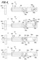
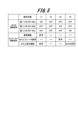
- FIG. 4 is a diagram for explaining the elevator inspection method according to the embodiment, and is a diagram showing each operating state (1) to (4) of the movement regulating mechanism 20 operated by a worker. Further, FIG. 5 is a comparison diagram of the connection state of the connector and the control state of the elevator in each operating state (1) to (4) of the movement regulating mechanism.
- the elevator inspection method explained based on these figures includes the work procedure carried out by a worker when inspecting the brakes of the hoisting machine 16 shown in FIG. This is a control method implemented by the control device 17.
- the control performed by the elevator control device 17 is control performed according to an inspection program stored in the elevator control device 17.
- This inspection program is a program that allows or disables each control of the elevator 1 based on signals from the first connector 105a, the second connector 105b, and the third connector 105c.
- an elevator inspection method will be described based on FIGS. 4 and 5 and with reference to FIG. 1.
- the short connector 104 is inserted into the first connector 105a, and the first connector 105a is in the connected state (ON).
- the second connector 105 and the third connector 105c are not connected (OFF).
- the elevator control device 17 permits normal operation based on the signal from the first connector 105a. Further, the elevator control device 17 disables (-) the operation unit 12 from operating the brake of the hoisting machine 16 on the car. Further, the elevator control device 17 allows the operation unit 12 to perform maintenance operations on the car.
- the worker pulls out the short connector 104 from the first connector 105a, and disconnects the first connector 105a, leaving it unconnected (OFF). As a result, the worker puts the first connector 105a, the second connector 105b, and the third connector 105c into a second state (2) in which they are all unconnected (OFF).
- the elevator control device 17 disables (-) the normal operation of the elevator 1 based on the signal from the second connector 105b, and controls the operation of the hoisting machine 16 on the car by the operation unit 12. Brake operation is permitted, and maintenance operation on the car by the operation unit 12 is disabled (-).
- the worker also sets the brake of the hoisting machine 16 and finishes the inspection.
- the worker rotates the lever 103 around the stopper pin 101 within the second fitting part 102e of the regulating wall 102c, and fits the lever 103 into the deepest part of the second fitting part 102e.
- the worker inserts the short connector 104 fixed to the lever 103 into the third connector 105c to bring the third connector 105c into a fourth state (4) in the connected state (ON).
- the elevator control device 17 disables (-) normal operation of the elevator 1 based on the signal from the third connector 105c, and controls the operation of the hoisting machine 16 on the car by the operation unit 12. Brake operation is disabled (-), and only the operation of lowering the car 10 among the maintenance operations on the car using the operation unit 12 is permitted. In this state, the brake operation of the hoisting machine 16 on the car by the operation unit 12 is disabled (-), so the car 10 will not be in a free running state, and the worker on the car safety will be ensured.
- the worker rotates the lever 103 around the stopper pin 101 under the control of the elevator control device 17 in the second state (2), and detaches the lever 103 from the second fitting part 102e of the regulation wall 102c. .
- the stopper pin 101 is housed in the support housing 102, and the restriction on movement of the car 10 is released.
- the brake of the hoist 16 since the brake of the hoist 16 is in the set state, the safety of the worker on the car 10 is ensured.
- the first state (1) is a connected state (ON).
- the elevator control device 17 allows normal operation based on the signal from the first connector 105a, and disallows the brake operation of the hoisting machine 16 on the car by the operation unit 12 (- ), permit maintenance operation on the car using the operation unit 12.
- the signals from the first connector 105a, which can be connected only when the stopper pin 101 is housed, and the second connector 105b, which can be connected only when the stopper pin 101 is protruded Based on this, the elevator control device 17 controls the travel of the car 10, thereby ensuring the safety of workers on the car 10 during inspection work.
- the present invention is not limited to the above-described embodiments and modifications, and includes various modifications.
- the above-described embodiments have been described in detail to explain the present invention in an easy-to-understand manner, and the present invention is not necessarily limited to having all the configurations described.
Landscapes
- Engineering & Computer Science (AREA)
- Mechanical Engineering (AREA)
- Maintenance And Inspection Apparatuses For Elevators (AREA)
- Elevator Control (AREA)
- Cage And Drive Apparatuses For Elevators (AREA)
Abstract
Description
本願は上記課題を解決する手段を複数含んでいるが、その一例を挙げるならば、乗りカゴと、前記乗りカゴの移動を規制するための移動規制機構と、前記乗りカゴの走行を制御する制御装置とを有するエレベーターであって、前記移動規制機構は、前記乗りカゴから水平方向に突出自在な棒状のストッパーピンと、前記ストッパーピンが前記乗りカゴに対して収容された状態でのみ接続可能となる第1コネクタと、前記ストッパーピンが前記乗りカゴから突出した状態でのみ接続可能となる第2コネクタとを備え、前記制御装置は、前記第1コネクタと前記第2コネクタの接続状態に基づいて前記乗りカゴの走行を制御するエレベーターである。
図1は、実施形態に係るエレベーター1の概略構成を説明するための全体図である。この図に示すエレベーター1は、乗りカゴ10、かご枠11、操作部12、ガイドレール13、釣合い錘14、主ロープ15、巻上機16、エレベーター制御装置17を有する。さらにエレベーター1は、エレベーター1の点検時において乗りカゴ10の移動を規制するための移動規制機構20を備える。これらは次のように構成されている。
乗りかご10は、箱形状のものであり、側壁の一部には乗りカゴ10内に乗降するためのかごドア10aが設けられている。またかご枠11は、乗りカゴ10の側壁のうちのかごドア10aが設けられていない面において、乗りカゴ10を縦方向に一周するように配置され、乗りカゴ10に固定されている。このようなかご枠11は、例えばその四隅に、乗りカゴ10から水平方向の外側に向かって突出させた状態でガイド部11aが固定さている。ガイド部11aは、乗りカゴ10の走行を案内するためのものである。またかご枠11の下部には、一対のプーリー11bが固定されている。これらのプーリー11bは、乗りカゴ10を吊り下げるための主ロープ15が摺動自在にかけ渡される。
操作部12は、エレベーター1の点検に際して、例えば以降に説明する巻上機16のブレーキを解除するための信号、さらには保守運転のための操作信号を入力するための操作部分である。この操作部12は、以降に説明するエレベーター制御装置17に対して、無線または有線で操作信号を送信する。このような操作部12は、乗りカゴ10に対して直接、またはかご枠11を介して固定されている。
ガイドレール13は、乗りカゴ10を挟む位置において乗りカゴ10の両脇に立設されたものである。これらの各ガイドレール13は、かご枠11の上下に固定された各ガイド部11aがそれぞれ摺動自在に係合し、乗りカゴ10の走行を案内する。
釣合い錘14は、乗りカゴ10との釣り合いをとるためのものである。主ロープ15は、かご枠11を介して乗りカゴ10に固定されたプーリー11bにかけ渡され、乗りカゴ10と釣合い錘14とを釣る瓶状に吊り下げる。また巻上機16は、主ロープ15の中間部分が巻き掛けられた状態で駆動し、主ロープ15に釣り下げられた乗りカゴ10を走行させる。
エレベーター制御装置17は、乗りカゴ10の走行およびかごドア10aの開閉を制御する。エレベーター制御装置17による乗りカゴ10およびかごドア10aの駆動の制御は、ここでの図示を省略した乗り場呼びボタンおよびかご呼びボタン、先に説明した操作部12、さらには以降に説明する移動規制機構20からの信号に基づいて実施される。
図2および図3は、実施形態に係るエレベーターに設けられる移動規制機構20の構成を示す図(その1)および(その2)である。これらの図2および図3は、図1に示す2つの移動規制機構20のうち、図面上の左側の移動規制機構20の正面図(図2A,図3B)と上面図(図2B,図3B)である。以下、これらの図2、図3、および先に説明した図1に基づいて、移動規制機構20の構成を説明する。
ピンユニット100は、かご枠11を介して乗りカゴ10に固定されたものであり、かご枠11の上部において、その両端に固定されたものである。このようなピンユニット100は、ストッパーピン101、支持筐体102、レバー103、ショートコネクタ104、さらに第1コネクタ105a、第2コネクタ105b、および第3コネクタ105cを有する。またピンユニット100は、支持筐体102において、ビスのような固定部材106を用いてかご枠11に対して固定されている。ピンユニット100を構成する各部は、次のようである。
ストッパーピン101は、円柱形の棒状のものであって、次に説明する支持筐体102に支持された状態で、乗りカゴ10に対して水平方向の外側に突出自在である。このストッパーピン101は、かご枠11から以降に説明する規制板200に届く程度に十分な長さを有する。
支持筐体102は、かご枠11に固定された状態で設けられたもので、乗りカゴ10およびかご枠11に対して水平方向の外側に対してストッパーピン101を突出自在に支持する。このような支持筐体102は、平行に配置された2枚の軌道壁102a,102bを備える。これらの軌道壁102a,102bは、ストッパーピン101が摺動自在に挿通される貫通孔102aa,102bbを有し、ストッパーピン101の移動方向を規制する。またこれとともに、軌道壁102a,102bは、貫通孔102aa、102bbにストッパーピン101を挿通させることにより、ストッパーピン101を支持する。このような軌道壁102a,102bはストッパーピン101の長さの二分の一程度の間隔で配置されている。
レバー103は、ストッパーピン101の側周壁からストッパーピン101の軸方向に対して垂直に延設されたものであって、ストッパーピン101を軸回りに回転させるとともに、ストッパーピン101を軸方向に移動させるための操作部である。このレバー103は、ストッパーピン101の回転と移動により、第1嵌合部102dおよび第2嵌合部102eのそれぞれに対して嵌入自在な突出長さ、および径を有する。またレバー103は、作業員によるストッパーピン101の回転および移動の操作を容易とする形状を有する。
ショートコネクタ104は、次に説明する第1コネクタ105a、第2コネクタ105b、および第3コネクタ105cの3つのコネクタのうちの何れかを導通させた接続状態とするためのものであり、例えばこれらの何れかに差し込まれる。このようなショートコネクタ104は、レバー103に取り付けられ、レバー103と共に第1嵌合部102dおよび第2嵌合部102eの間で移動する。
第1コネクタ105a、第2コネクタ105b、および第3コネクタ105cは、ショートコネクタ104の差し込みにより導通した接続状態となり、接続状態となった信号をエレベーター制御装置17に送信する。
規制板200は、ガイドレール13の所定高さに固定されたものであり、ピンユニット100のストッパーピン101が嵌入する嵌入孔201を有する。規制板200は、ストッパーピン101が嵌入孔201に嵌入されることにより、乗りカゴ10の移動を規制する。
図4は、実施形態に係るエレベーターの点検方法を説明する図であり、作業員によって操作された移動規制機構20の各動作状態(1)~(4)を示す図である。また図5は、移動規制機構の各動作状態(1)~(4)におけるコネクタの接続状態とエレベーターの制御状態との対比図である。
先ず第1状態(1)は、第1コネクタ105aに対してショートコネクタ104が差し込まれ、第1コネクタ105aが接続状態(ON)となっている。これにより第2コネクタ105および第3コネクタ105cは未接続(OFF)となっている。この第1状態(1)において、エレベーター制御装置17は、第1コネクタ105aからの信号に基づいて、通常運転を許可している。またエレベーター制御装置17は、操作部12によるかご上での巻上機16のブレーキ操作を不可(-)としている。さらにエレベーター制御装置17は、操作部12によるかご上での保守運転を許可している。
以上のような第1状態(1)において、作業員は、巻上機16のエレベーター1の点検を目的として、所定の高さ位置に移動させたエレベーター1の乗りカゴ10の上部に登る。この状態において、操作部12によるかご上での巻上機16のブレーキ操作は不可(-)となっているため、乗りカゴ10がフリーラン状態となることはなく、乗りカゴ10上における作業員の安全は確保されている。
第2状態(2)において、エレベーター制御装置17は、通常運転を不可(-)とし、さらに操作部12によるかご上での巻上機16のブレーキ操作および保守運転を不可(-)とする。これにより第2状態(2)においては、乗りカゴ10上の作業員の安全は確保される。
作業員は、第2状態(2)でのエレベーター制御装置17による制御下において、ストッパーピン101を軸としてレバー103を回転させ、規制壁102cの第1嵌合部102dとレバー103との嵌合状態を解除する。次いで、レバー103を第2嵌合部102e側に移動させることで、ストッパーピン101を支持筐体102から突出させ、ストッパーピン101の先端を規制板200の嵌入孔201に嵌入させる。これにより、乗りカゴ10の移動を規制する。
次に作業員は、レバー103の位置を規制壁102cの第2嵌合部102eに合わせ、ストッパーピン101を軸としてレバー103を回転させて規制壁102cの第2嵌合部102eにレバー103を嵌入させる。この状態で、作業員は、レバー103に固定されたショートコネクタ104を第2コネクタ105bに差し込み、第2コネクタ105bを接続状態(ON)とした第3状態(3)とする。
第3状態(3)において、エレベーター制御装置17は、第2コネクタ105bからの信号に基づいて、エレベーター1の通常運転を不可(-)とし、操作部12によるかご上での巻上機16のブレーキ操作を許可し、操作部12によるかご上で保守運転を不可(-)とする。
作業員は、第3状態(3)でのエレベーター制御装置17による制御下において、操作部12での操作により巻上機16のブレーキ点検を実施する。この際、作業員は、巻上機16のブレーキを解除し、乗りカゴ10と釣合い錘14の移動が巻上機16によって規制されないフリー状態とする。これにより、典型的には乗りカゴ10が上昇する方向に移動するフリーラン状態となるが、ストッパーピン101が規制板200の嵌入孔201に嵌入しているため、乗りカゴ10のフリーランが防止される。したがって、乗りカゴ10上における作業員の安全は確保される。
その後、作業員は、ショートコネクタ104を、第2コネクタ105bから抜き取り、第2コネクタ105bの接続状態を解除する。これにより、一時的に、第1コネクタ105a、第2コネクタ105b、および第3コネクタ105cの何れも未接続(OFF)な第2状態(2)となる。この第2状態(2)において、エレベーター制御装置17は、通常運転を不可(-)とし、さらに操作部12によるかご上での巻上機16のブレーキ操作および保守運転を不可(-)とするため、作業員の安全は確保される。
第4状態(4)において、エレベーター制御装置17は、第3コネクタ105cからの信号に基づいて、エレベーター1の通常運転を不可(-)とし、操作部12によるかご上での巻上機16のブレーキ操作を不可(-)とし、操作部12によるかご上での保守運転のうち、乗りカゴ10を降下させる操作のみを許可する。この状態において、操作部12によるかご上での巻上機16のブレーキ操作は不可(-)となっているため、乗りカゴ10がフリーラン状態となることはなく、乗りカゴ10上における作業員の安全は確保される。
作業員は、第4状態(4)でのエレベーター制御装置17による制御下において、操作部12での保守運転操作により、乗りカゴ10を僅かに降下させる。これにより、ストッパーピン101と規制板200との固渋状態を解消する。すなわち、先に実施した巻上機16のブレーキ点検においては、巻上機16のブレーキを解除した場合の乗りカゴ10の移動によりストッパーピン101と規制板200とが固渋し、ストッパーピン101の移動が困難な状態となっている。このため、操作部12での保守運転操作により、乗りカゴ10を僅かに降下させることで固渋状態を解消するのである。
その後、作業員は、ショートコネクタ104を、第3コネクタ105cから抜き取り、第3コネクタ105cの接続状態を解除し、第1コネクタ105a、第2コネクタ105b、および第3コネクタ105cの何れも未接続(OFF)な第2状態(2)とする。この第2状態(2)において、エレベーター制御装置17は、通常運転を不可とし、さらに操作部12によるかご上での巻上機16のブレーキ操作および保守運転を不可とするため、作業員の安全は確保される。
以上説明した実施形態によれば、ストッパーピン101が収容された状態でのみ接続可能となる第1コネクタ105aと、ストッパーピン101が突出した状態でのみ接続可能となる第2コネクタ105bからの信号に基づいて、エレベーター制御装置17が乗りカゴ10の走行制御を行うことで、点検作業に際して、乗りカゴ10上においての作業員の安全性を確実に確保することが可能である。
10…乗りカゴ
12…操作部
16…巻上機
17…エレベーター制御装置
20…移動規制機構
100…ピンユニット
101…ストッパーピン
102…支持筐体
102a,102b…軌道壁
102aa,102bb…貫通孔
102c…規制壁
102d…第1嵌合部
102e…第2嵌合部
103…レバー
104…ショートコネクタ
105a…第1コネクタ
105b…第2コネクタ
105c…第3コネクタ
200…規制板
201…嵌入孔
Claims (15)
- 乗りカゴと、前記乗りカゴの移動を規制するための移動規制機構と、前記乗りカゴの走行を制御する制御装置とを有するエレベーターであって、
前記移動規制機構は、
前記乗りカゴから水平方向に突出自在な棒状のストッパーピンと、
前記ストッパーピンが前記乗りカゴに対して収容された状態でのみ接続可能となる第1コネクタと、前記ストッパーピンが前記乗りカゴから突出した状態でのみ接続可能となる第2コネクタとを備え、
前記制御装置は、前記第1コネクタと前記第2コネクタの接続状態に基づいて前記乗りカゴの走行を制御する
エレベーター。 - 前記制御装置は、
前記第1コネクタが接続された状態でのみ、前記乗りカゴの通常走行を許可する
請求項1に記載のエレベーター。 - 前記乗りカゴの上部に設けられた操作部と、
前記乗りカゴを走行させる巻上機とを有し、
前記制御装置は、
前記第2コネクタが接続された状態でのみ前記操作部による前記巻上機のブレーキの解除を許可する
請求項1に記載のエレベーター。 - 前記移動規制機構は、前記乗りカゴから突出した前記ストッパーピンが嵌入する嵌入孔を有して前記乗りカゴが走行する走行路内に固定された規制板を備えた
請求項1に記載のエレベーター。 - 前記移動規制機構は、前記ストッパーピンを前記乗りカゴから水平方向に突出自在に支持する支持筐体を備えた
請求項1に記載のエレベーター。 - 前記支持筐体は、前記ストッパーピンを摺動自在に貫通させる貫通孔を有して対向配置された複数の軌道壁を有する
請求項5に記載のエレベーター。 - 前記移動規制機構は、
前記ストッパーピンの突出を操作するために前記ストッパーピンに固定されたレバーと、
前記第1コネクタおよび前記第2コネクタをそれぞれ個別に接続状態とするためのものであって前記レバーに固定されたショートコネクタとを備えた
請求項1に記載のエレベーター。 - 前記移動規制機構は、
前記ストッパーピンが前記乗りカゴに対して収容された位置において前記レバーと嵌合する第1嵌合部と、前記ストッパーピンが前記乗りカゴから突出した位置において前記レバーと嵌合する第2嵌合部とが設けられた前記ストッパーピンの支持筐体を備えた
請求項7に記載のエレベーター。 - 前記第1嵌合部と前記第2嵌合部とは、前記ストッパーピンの軸に対して平行に配置された規制壁に形成された切り欠きであり、
前記レバーは、前記ストッパーピンの側周壁に突設されている
請求項8に記載のエレベーター。 - 前記第1コネクタおよび前記第2コネクタは、前記規制壁に固定されている
請求項9に記載のエレベーター。 - 前記移動規制機構は、前記ストッパーピンが前記乗りカゴから突出した状態で、かつ前記第2コネクタと未接続な状態においてのみ接続可能となる第3コネクタを備えた
請求項1に記載のエレベーター。 - 前記乗りカゴの上部に設けられた操作部を有し、
前記制御装置は、前記第3コネクタが接続された状態でのみ、前記操作部による前記乗りカゴの保守運転を許可する
請求項11に記載のエレベーター。 - 乗りカゴから水平方向に突出自在な棒状のストッパーピンと、前記ストッパーピンが前記乗りカゴに対して収容された状態でのみ接続可能となる第1コネクタと、前記ストッパーピンが前記乗りカゴから突出した状態でのみ接続可能となる第2コネクタとを備えた前記乗りカゴの移動規制機構と、前記第1コネクタと前記第2コネクタの接続状態に基づいて前記乗りカゴの走行を制御する制御装置とを有するエレベーターの点検方法であって、
前記第1コネクタを接続状態とした前記制御装置による制御下において前記第1コネクタを未接続状態とする第1のステップと、
前記第1コネクタおよび第2コネクタを未接続とした状態での前記制御装置による制御下において前記乗りカゴから前記ストッパーピンを突出させて前記乗りカゴの移動を規制する第2のステップと、
前記第2コネクタを接続状態とする第3のステップと、
前記第2コネクタを接続状態とした状態での前記制御装置による制御下においてエレベーターの点検を実施する第4のステップとを実施する
エレベーターの点検方法。 - 前記エレベーターは、前記乗りカゴの上部に設けられた操作部と、前記乗りカゴを走行させる巻上機とを有し、
前記第2のステップは、前記制御装置によって通常運転および前記操作部による前記巻上機のブレーキの解除操作を不可とした制御下において実施し、
前記第4のステップは、前記制御装置によって通常運転を不可とし前記操作部による前記巻上機のブレーキの解除操作を許可した制御下において実施する
請求項13に記載のエレベーターの点検方法。 - 前記移動規制機構は、前記ストッパーピンが前記乗りカゴから突出した状態で、かつ前記第2コネクタと未接続な状態においてのみ接続可能となる第3コネクタを備えており、
前記第4のステップの後、
前記第2コネクタを未接続として前記第3コネクタを接続状態とする第5のステップと、
前記第3コネクタを接続状態とした前記制御装置による制御下においてエレベーターの保守運転を実施する第6のステップとを実施する
請求項13に記載のエレベーターの点検方法。
Priority Applications (3)
| Application Number | Priority Date | Filing Date | Title |
|---|---|---|---|
| JP2024520195A JP7723197B2 (ja) | 2022-05-13 | 2022-05-13 | エレベーターおよびエレベーターの点検方法 |
| PCT/JP2022/020142 WO2023218620A1 (ja) | 2022-05-13 | 2022-05-13 | エレベーターおよびエレベーターの点検方法 |
| CN202280095161.6A CN119072447A (zh) | 2022-05-13 | 2022-05-13 | 电梯以及电梯的检修方法 |
Applications Claiming Priority (1)
| Application Number | Priority Date | Filing Date | Title |
|---|---|---|---|
| PCT/JP2022/020142 WO2023218620A1 (ja) | 2022-05-13 | 2022-05-13 | エレベーターおよびエレベーターの点検方法 |
Publications (1)
| Publication Number | Publication Date |
|---|---|
| WO2023218620A1 true WO2023218620A1 (ja) | 2023-11-16 |
Family
ID=88730176
Family Applications (1)
| Application Number | Title | Priority Date | Filing Date |
|---|---|---|---|
| PCT/JP2022/020142 Ceased WO2023218620A1 (ja) | 2022-05-13 | 2022-05-13 | エレベーターおよびエレベーターの点検方法 |
Country Status (3)
| Country | Link |
|---|---|
| JP (1) | JP7723197B2 (ja) |
| CN (1) | CN119072447A (ja) |
| WO (1) | WO2023218620A1 (ja) |
Citations (3)
| Publication number | Priority date | Publication date | Assignee | Title |
|---|---|---|---|---|
| JP2000203774A (ja) * | 1998-11-12 | 2000-07-25 | Toshiba Corp | エレベ―タ籠の停止ロック装置 |
| JP2011524316A (ja) * | 2008-06-03 | 2011-09-01 | オーチス エレベータ カンパニー | エレベータの(電気的)個別ブレーキシュー検査 |
| JP2014012581A (ja) * | 2012-07-04 | 2014-01-23 | Toshiba Elevator Co Ltd | エレベータ装置 |
-
2022
- 2022-05-13 JP JP2024520195A patent/JP7723197B2/ja active Active
- 2022-05-13 CN CN202280095161.6A patent/CN119072447A/zh active Pending
- 2022-05-13 WO PCT/JP2022/020142 patent/WO2023218620A1/ja not_active Ceased
Patent Citations (3)
| Publication number | Priority date | Publication date | Assignee | Title |
|---|---|---|---|---|
| JP2000203774A (ja) * | 1998-11-12 | 2000-07-25 | Toshiba Corp | エレベ―タ籠の停止ロック装置 |
| JP2011524316A (ja) * | 2008-06-03 | 2011-09-01 | オーチス エレベータ カンパニー | エレベータの(電気的)個別ブレーキシュー検査 |
| JP2014012581A (ja) * | 2012-07-04 | 2014-01-23 | Toshiba Elevator Co Ltd | エレベータ装置 |
Also Published As
| Publication number | Publication date |
|---|---|
| CN119072447A (zh) | 2024-12-03 |
| JP7723197B2 (ja) | 2025-08-13 |
| JPWO2023218620A1 (ja) | 2023-11-16 |
Similar Documents
| Publication | Publication Date | Title |
|---|---|---|
| JP4107728B2 (ja) | エレベータ装置 | |
| US6230845B1 (en) | Moveable control panel for elevators | |
| US7721852B2 (en) | Control device of elevator | |
| CN102448863A (zh) | 电梯的安全装置 | |
| CN109502442A (zh) | 电梯紧急停止系统 | |
| CN107810157B (zh) | 井道中的电梯轿厢位置区域 | |
| WO2023218620A1 (ja) | エレベーターおよびエレベーターの点検方法 | |
| CN110719882A (zh) | 电梯的底坑梯子装置 | |
| JPWO2005115898A1 (ja) | エレベータ制御装置 | |
| CN101759074A (zh) | 电梯设备 | |
| JP3603606B2 (ja) | エレベータ装置 | |
| JP5079326B2 (ja) | エレベータ制御装置 | |
| CN103079980B (zh) | 电梯设备 | |
| KR101022122B1 (ko) | 위치검출장치, 엘리베이터의 위치검출장치 및 엘리베이터 장치 | |
| JP4447962B2 (ja) | エレベータのかご保持装置 | |
| CN102530665B (zh) | 电梯设备 | |
| JP7823779B1 (ja) | エレベーター制御装置及びエレベーターの制御方法 | |
| JP3152001B2 (ja) | エレベーター装置 | |
| WO2023243074A1 (ja) | エレベーターおよび乗りカゴの固定装置 | |
| JP2021004116A (ja) | エレベーター煙感知器用の点検支援窓装置 | |
| JP2016216189A (ja) | エレベータのかご移動制止装置 | |
| JP7655424B1 (ja) | エレベータ | |
| CN116331967B (zh) | 升降机运转控制装置及其方法 | |
| JP5902135B2 (ja) | 階間調整機能付きエレベータ | |
| JP7782747B1 (ja) | エレベータシステム |
Legal Events
| Date | Code | Title | Description |
|---|---|---|---|
| 121 | Ep: the epo has been informed by wipo that ep was designated in this application |
Ref document number: 22941699 Country of ref document: EP Kind code of ref document: A1 |
|
| WWE | Wipo information: entry into national phase |
Ref document number: 2024520195 Country of ref document: JP |
|
| WWE | Wipo information: entry into national phase |
Ref document number: 202280095161.6 Country of ref document: CN |
|
| WWE | Wipo information: entry into national phase |
Ref document number: 202417087278 Country of ref document: IN |
|
| NENP | Non-entry into the national phase |
Ref country code: DE |
|
| 122 | Ep: pct application non-entry in european phase |
Ref document number: 22941699 Country of ref document: EP Kind code of ref document: A1 |