WO2023218571A1 - 支援装置、支援方法およびプログラム - Google Patents
支援装置、支援方法およびプログラム Download PDFInfo
- Publication number
- WO2023218571A1 WO2023218571A1 PCT/JP2022/019984 JP2022019984W WO2023218571A1 WO 2023218571 A1 WO2023218571 A1 WO 2023218571A1 JP 2022019984 W JP2022019984 W JP 2022019984W WO 2023218571 A1 WO2023218571 A1 WO 2023218571A1
- Authority
- WO
- WIPO (PCT)
- Prior art keywords
- displacement
- vibration
- support device
- target object
- mode shape
- Prior art date
- Legal status (The legal status is an assumption and is not a legal conclusion. Google has not performed a legal analysis and makes no representation as to the accuracy of the status listed.)
- Ceased
Links
Images


Classifications
-
- G—PHYSICS
- G01—MEASURING; TESTING
- G01M—TESTING STATIC OR DYNAMIC BALANCE OF MACHINES OR STRUCTURES; TESTING OF STRUCTURES OR APPARATUS, NOT OTHERWISE PROVIDED FOR
- G01M7/00—Vibration-testing of structures; Shock-testing of structures
- G01M7/02—Vibration-testing by means of a shake table
Definitions
- the present disclosure relates to a support device, a support method, and a program.
- the natural frequency of the structure is measured through modal experiments to prevent resonance from occurring in the structure.
- the most common and simple method of modal experiment is a method using an impulse hammer and an accelerometer.
- the attenuation becomes large in large structures such as civil engineering structures, making accurate measurement difficult.
- a vibrator (modal vibrator) is used.
- a modal vibrator By using a modal vibrator, it is possible to increase the excitation force on the target object, making accurate measurement possible.
- vibration using a modal vibrator it is difficult to select the vibration point at which the object is to be vibrated by the modal vibrator, and if the vibration point is selected incorrectly, correct measurement results cannot be obtained.
- Non-Patent Document 1 describes a method of vibrating an object with an impulse hammer and searching for an excitation point.
- Non-Patent Document 1 In the method described in Non-Patent Document 1, it depends on the experimenter which point to explore, and there is a possibility that an appropriate excitation point may be missed.
- the purpose of the present disclosure which was made in view of the above-mentioned problems, is to support the determination of the excitation point at which the object is to be excited in a measurement system that vibrates the object and measures the vibrations generated in the object.
- the goal is to provide support devices, support methods, and programs that can help.
- a support device supports determination of an excitation point at which to vibrate the target object in a measurement system that vibrates the target object and measures vibrations generated in the target object.
- the support device includes a target pattern attached to the target object that is displaced in accordance with the vibration of the target object, and based on the displacement of the target pattern in a moving image taken of the vibrated target object, a displacement measurement unit that measures the planar or spatial displacement of the object in time series; and a displacement measurement unit that measures the displacement at the response point measured by the displacement measurement unit for each of the plurality of response points on the object.
- a frequency calculation unit extracts the frequency at which the vibration amplitude peaks by performing FFT calculation on the vibration amplitude, and a frequency calculation unit extracts the frequency at which the vibration amplitude peaks.
- a mode shape calculation unit that analyzes a mode shape in a vibration mode; and a selection unit that selects a position that is not a node in the mode shape of each vibration mode analyzed by the mode shape calculation unit as the excitation point. Be prepared.
- a support method includes determining an excitation point at which the object is to be excited in a measurement system that vibrates the object and measures vibrations generated in the object.
- the object is provided with a target pattern that is displaced in response to vibrations of the object, and the object is provided with a target pattern that is displaced in response to vibrations of the object, and the object is provided with a target pattern that changes depending on the displacement of the target pattern in a moving image taken of the vibrated object.
- a program according to the present disclosure causes a computer to operate as the above-mentioned support device.
- the support device, support method, and program according to the present disclosure it is possible to support determination of an excitation point at which to vibrate a target object in a measurement system that vibrates the target object and measures vibrations generated in the target object. I can do it.
- FIG. 1 is a diagram illustrating a configuration example of a support device according to an embodiment of the present disclosure.
- FIG. 2 is a diagram for explaining a moving image used for selecting an excitation point by the support device shown in FIG. 1.
- FIG. 2 is a flowchart showing an example of the operation of the support device shown in FIG. 1.
- FIG. FIG. 1 is a diagram illustrating an example of a hardware configuration of a support device according to the present disclosure.
- FIG. 1 is a diagram illustrating a configuration example of a support device 10 according to an embodiment of the present disclosure.
- the support device 10 according to the present embodiment supports determination of an excitation point at which to vibrate a target object in a measurement system that vibrates the target object and measures vibrations generated in the target object.
- a target pattern 2 is attached to the object 1, as shown in FIG. Then, the object 1 with the target pattern 2 attached thereto is vibrated, and the vibrated object 1 is photographed by the photographing device 3.
- the target pattern 2 is displaced according to the vibration of the object 1. By observing the displacement of the target pattern 2, the vibration of the object 1 can be observed. That is, the target pattern 2 allows the vibration of the object 1 to be visually detected.
- the target pattern 2 may be, for example, a marker used in motion capture. Further, the target pattern 2 may be, for example, a speckle pattern used in Digital Image Correlation (DIC). However, the target pattern 2 is not limited to these examples, and may be any pattern that allows the vibration of the target object 1 to be visually detected.
- a method of vibrating the object 1 there is a method of hitting the object 1 with a hammer or the like, for example. This method is simple, but if the object 1 is a large structure, it is difficult to hit with enough energy to vibrate the object 1.
- another method of vibrating the object 1 there is a method using natural vibration (excitation caused by wind or vibration caused by the surrounding environment of the object 1). With this method, the amplitude of the vibration of the object 1 may become small. In this case, it is necessary to use a photographing device 3 with high resolution or to bring the photographing device 3 close to the object 1 to photograph the object. Any method may be used to vibrate the object 1 depending on the object 1 and the required magnitude of vibration.
- the support device 10 includes a moving image input section 11, a displacement measurement section 12, a frequency calculation section 13, a mode shape calculation section 14, a selection section 15, and an output section. 16.
- the moving image input unit 11 receives a moving image captured by the imaging device 3. As mentioned above, the target pattern 2 is attached to the object 1, and the moving image taken by the photographing device 3 shows that the object 1 with the target pattern 2 attached is vibrated, and the object 1 is attached with the target pattern 2. 1 was taken.
- the moving image input section 11 outputs the input moving image to the displacement measuring section 12.
- the displacement measurement unit 12 measures the planar (two-dimensional) or spatial (three-dimensional) displacement of the object 1 in time series based on the displacement of the target pattern 2 in the video output from the video input unit 11. Measure accurately. For example, when the target pattern 2 is a predetermined marker, the displacement measuring unit 12 detects the position of the marker in the moving image by motion capture, thereby measuring the planar or spatial displacement of the object 1 in time series. measure. Further, for example, when the target pattern 2 is a speckle pattern, the displacement measurement unit 12 measures the planar or spatial displacement of the object 1 in time series using a digital image correlation method using the speckle pattern. do. In addition, when measuring the planar displacement of the target object 1, it is sufficient to photograph the target object 1 with the target pattern 2 attached using one photographing device 3. Furthermore, when measuring the spatial displacement of the object 1, the object 1 to which the target pattern 2 is attached may be photographed using two or more photographing devices 3.
- the displacement measurement unit 12 outputs the measurement result of the displacement of the target object 1 to the frequency calculation unit 13.
- the frequency calculation unit 13 extracts the frequency at which the amplitude of the vibration of the target object 1 reaches its peak, based on the measurement result of the displacement of the target object 1 by the displacement measurement unit 12. Specifically, the frequency calculation unit 13 performs FFT (Fast Fourier Transform) calculation on the displacement at the response point measured by the displacement measurement unit 12 for each of the plurality of response points on the object 1. Then, a frequency spectrum of the vibration of the object 1 is generated. Then, the frequency calculation unit 13 extracts a frequency at which the amplitude of vibration is at a peak from the generated frequency spectrum for each of the plurality of response points on the object 1. The frequency calculation unit 13 outputs the extraction result to the mode shape calculation unit 14. Note that an arbitrary number of response points may be set at arbitrary points on the object 1 in the moving image photographed by the photographing device 3.
- FFT Fast Fourier Transform
- the mode shape calculation unit 14 analyzes the mode shape (distribution of displacement due to vibration) in each vibration mode to be measured, based on the peaks extracted for each of the plurality of response points by the frequency calculation unit 13.
- ODS Operating Deflection Shapes
- ODS analysis is a method of graphically expressing the displacement of an object during vibration. Since ODS analysis itself is a technique well known to those skilled in the art, detailed explanation will be omitted.
- information on the amplitude of vibration as well as information on the phase of the amplitude is required.
- the phase information can be obtained, for example, by FFT calculation by the frequency calculation unit 13.
- the mode shape calculation unit 14 outputs the mode shape analysis results for each vibration mode to be measured to the selection unit 15.
- the selection unit 15 selects, as an excitation point, a position that is not a node in the mode shape of each vibration mode analyzed by the mode shape calculation unit 14.
- the selection unit 15 outputs the selection result of the vibration point to the output unit 16.
- the output unit 16 outputs the selection result of the excitation point by the selection unit 15.
- the output unit 16 displays and outputs the selection result of the selection unit 15 on a display device, for example. Further, the output unit 16 outputs the selection result by the selection unit 15 in audio, for example.
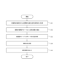
- FIG. 3 is a flowchart showing an example of the operation of the support device 10 according to the present embodiment, and is a diagram for explaining a support method by the support device 10.
- the displacement measuring unit 12 determines the target pattern 2 based on the displacement of the target pattern 2 in the video image input to the video image input unit 11 in which the target pattern 2 is attached and the target object 1 is in a vibrated state.
- the planar or spatial displacement of is measured over time (step S11).
- the frequency calculation unit 13 For each of the plurality of response points on the object 1, the frequency calculation unit 13 performs FFT calculation on the displacement at the response point measured by the displacement measurement unit 12. Thereby, the frequency calculation unit 13 generates a frequency spectrum of the vibration of the object 1 at each of the plurality of response points.
- the generated frequency spectrum has a peak at each frequency of each vibration mode, such as primary, secondary, tertiary, . . . .
- the frequency calculation unit 13 extracts a frequency at which the vibration amplitude is at a peak from the frequency spectrum generated for each response point (step S12).
- the frequency calculation unit 13 performs FFT calculation on the displacement at the response point in each of three orthogonal axes directions, and extracts a peak using at least one of the obtained frequency spectra of displacement in each direction. do.
- the mode shape calculation unit 14 analyzes the mode shape of each vibration mode to be measured, based on the peaks extracted for each of the plurality of response points by the frequency calculation unit 13 (step S13).
- the mode shape calculation unit 14 analyzes the mode shape of each vibration mode by, for example, the above-mentioned ODS analysis. As a result of the analysis, the mode shape calculation unit 14 generates a mode shape indicating the distribution of displacement due to vibration in each vibration mode (primary, secondary, . . . ) to be measured.
- the selection unit 15 superimposes the mode shapes in each vibration mode analyzed by the mode shape calculation unit 14, and selects a position that is not a node in the mode shape of each vibration mode as an excitation point (step S14).
- the output unit 16 outputs the selection result of the excitation point by the selection unit 15 (step S15).
- the output unit 16 displays and outputs the selection result by the selection unit 15 on a display device included in the support device 10 or a display device connected to the support device 10, for example. Further, the output unit 16 outputs the selection result by the selection unit 15 in audio, for example.
- each vibration mode to be measured is determined by FFT calculation and mode shape analysis.
- a mode shape is generated for.
- a position that is not a node in the mode shape of each vibration mode is selected as an excitation point.
- the excitation points selected in this way can excite the object 1 in all vibration modes to be measured. Therefore, according to the support device 10 and the support method using the support device 10 according to the present disclosure, it is possible to support the determination of the excitation point at which the object 1 is to be vibrated in the measurement system that measures vibrations occurring in the object 1. can.
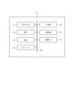
- FIG. 4 is a diagram showing an example of the hardware configuration of the support device 10 according to the present embodiment.
- FIG. 4 shows an example of the hardware configuration of the support device 10 in a case where the support device 10 is configured by a computer capable of executing program instructions.
- the computer may be a general-purpose computer, a dedicated computer, a workstation, a PC (Personal computer), an electronic notepad, or the like.
- Program instructions may be program code, code segments, etc. to perform necessary tasks.
- the support device 10 includes a processor 21, a ROM (Read Only Memory) 22, a RAM (Random Access Memory) 23, a storage 24, an input section 25, a display section 26, and a communication interface (I/F) 27. has.
- Each configuration is communicably connected to each other via a bus 29.
- the processor 21 is a CPU (Central Processing Unit), MPU (Micro Processing Unit), GPU (Graphics Processing Unit), DSP (Digital Signal Processor), SoC (System on a Chip), etc., and may be of the same or different type. It may be configured with a plurality of processors.
- the processor 21 is a control unit that controls each component and executes various calculation processes. That is, the processor 21 reads a program from the ROM 22 or the storage 24 and executes the program using the RAM 23 as a work area. The processor 21 controls each of the above components and performs various arithmetic operations according to programs stored in the ROM 22 or the storage 24. In this embodiment, the ROM 22 or the storage 24 stores a program for operating the computer as the support device 10 according to the present disclosure. Each configuration of the support device 10 described above is realized by reading and executing the program by the processor 21.
- Programs are stored in non-transitory storage media such as CD-ROM (Compact Disk Read Only Memory), DVD-ROM (Digital Versatile Disk Read Only Memory), and USB (Universal Serial Bus) memory. may be provided. Further, the program may be downloaded from an external device via a network.
- CD-ROM Compact Disk Read Only Memory
- DVD-ROM Digital Versatile Disk Read Only Memory
- USB Universal Serial Bus
- the ROM 22 stores various programs and various data.
- the RAM 23 temporarily stores programs or data as a work area.
- the storage 24 is configured with an HDD (Hard Disk Drive) or an SSD (Solid State Drive), and stores various programs including an operating system and various data.
- the input unit 25 includes a pointing device such as a mouse and a keyboard, and is used to perform various inputs.
- the display unit 26 is, for example, a liquid crystal display, and displays various information.
- the display unit 26 displays, for example, the result of the selection of the vibration point by the selection unit 15.
- the display section 26 may employ a touch panel method and function as the input section 25.
- the communication interface 27 is an interface for communicating with other devices, and is, for example, a LAN interface. For example, the result of the selection of the vibration point by the selection unit 15 is displayed on a display device connected to the support device 10 via the communication interface 27 .
- a computer can be suitably used to function as each part of the support device 10 described above.
- Such a computer is realized by storing a program that describes the processing contents for realizing the functions of each part of the support device 10 in the storage section of the computer, and having the processor of the computer read and execute this program. be able to. That is, the program can cause the computer to function as the support device 10 described above. It is also possible to record the program on a non-temporary storage medium. Moreover, it is also possible to provide the program via a network.
- a support device that supports determination of an excitation point to vibrate the target object, comprising: The target object is provided with a target pattern that is displaced in response to vibrations of the target object, memory and a control unit connected to the memory; Equipped with The control unit includes: Measuring the planar or spatial displacement of the object in time series based on the displacement of the target pattern in a moving image of the vibrated object; For each of the plurality of response points on the object, perform FFT calculation on the measured displacement at the response point to extract a frequency at which the amplitude of vibration is at a peak, Based on the peaks extracted for each of the plurality of response points, analyze the mode shape of each vibration mode to be measured, The support device selects, as the excitation point, a position that is not a node in the mode shape of each of the analyzed vibration modes.
- the target pattern is a predetermined marker
- the control unit is a support device that measures a planar or spatial displacement of the object based on a displacement of the marker in the moving image.
- the control unit is a support device that measures a planar or spatial displacement of the object using a digital image correlation method.
- a support method for supporting determination of an excitation point to vibrate the target object comprising: The target object is provided with a target pattern that is displaced in response to vibrations of the target object, Measuring the planar or spatial displacement of the object in time series based on the displacement of the target pattern in a moving image of the vibrated object; For each of the plurality of response points on the object, extracting a frequency at which the amplitude of vibration is at a peak by performing FFT calculation on the measured displacement at the response point; Analyzing the mode shape of each vibration mode to be measured based on the peaks extracted for each of the plurality of response points; A support method comprising the step of selecting, as the excitation point, a position that is not a node in the mode shape of each of the analyzed vibration modes.
- a non-temporary storage medium storing a program executable by a computer, the non-temporary storage medium storing a program that causes the computer to operate as the support device according to Supplementary Note 1.
Landscapes
- Physics & Mathematics (AREA)
- General Physics & Mathematics (AREA)
- Measurement Of Mechanical Vibrations Or Ultrasonic Waves (AREA)
Abstract
本開示に係る支援装置(10)は、加振された対象物(1)を撮影した動画像における、対象物(1)に付されたターゲット模様(2)の変位に基づき、対象物(1)の面的または空間的な変位を時系列的に計測する変位計測部(12)と、対象物上の複数の応答点それぞれについて、計測された当該応答点における変位に対してFFT計算を行うことで、振動の振幅がピークとなる周波数を抽出する周波数計算部(13)と、複数の応答点それぞれについて抽出されたピークに基づき、計測の対象とする各振動モードでのモード形状を解析するモード形状計算部(14)と、解析された各振動モードでのモード形状において節とならない位置を加振点と選定する選定部(15)と、を備える。
Description
本開示は、支援装置、支援方法およびプログラムに関する。
構造物を構築するにあたって、構造物に共振が発生しないように、モーダル実験により構造物の固有振動数などが計測される。モーダル実験の最も一般的で簡易な方法は、インパルスハンマと加速度計とを用いた方法である。しかしながら、この方法では、インパルスハンマで人力により構造物を打撃するため、土木構造物のような大型構造物では減衰が大きくなり、正しい計測が困難である。
そこで、例えば、大型構造物を計測の対象物とする場合には、加振器(モーダル加振器)が用いられる。モーダル加振器を使用することで、対象物に対する加振力を大きくすることができ、正しい計測が可能となる。ただし、モーダル加振器による加振は、対象物をモーダル加振器により加振する加振点の選定が難しく、加振点の選定を誤ると正しい計測結果が得られない。
加振点を選定するための方法として、非特許文献1には、インパルスハンマにより対象物を加振して加振点を探査する方法が記載されている。
「Frequently Asked Questions Modal Shakers and Related Topics」、The Modal Shop、[online]、[令和4年4月11日検索]、インターネット<URL:https://www.modalshop.com/filelibrary/Modal%20Shaker%20FAQ%20revA.pdf>
非特許文献1に記載の方法では、どの点を探査するかは実験者に依存しており、適切な加振点を見逃す可能性がある。
上記のような問題点に鑑みてなされた本開示の目的は、対象物を加振して、対象物に生じる振動を計測する計測系において、対象物を加振する加振点の決定を支援することができる支援装置、支援方法およびプログラムを提供することにある。
上記課題を解決するため、本開示に係る支援装置は、対象物を加振して、前記対象物に生じる振動を計測する計測系において、前記対象物を加振する加振点の決定を支援する支援装置であって、前記対象物には、前記対象物の振動に応じて変位するターゲット模様が付され、加振された前記対象物を撮影した動画像における前記ターゲット模様の変位に基づき、前記対象物の面的または空間的な変位を時系列的に計測する変位計測部と、前記対象物上の複数の応答点それぞれについて、前記変位計測部により計測された、当該応答点における変位に対してFFT計算を行うことで、振動の振幅がピークとなる周波数を抽出する周波数計算部と、前記周波数計算部により前記複数の応答点それぞれについて抽出されたピークに基づき、計測の対象とする各振動モードでのモード形状を解析するモード形状計算部と、前記モード形状計算部により解析された前記各振動モードでのモード形状において節とならない位置を前記加振点と選定する選定部と、を備える。
また、上記課題を解決するため、本開示に係る支援方法は、対象物を加振して、前記対象物に生じる振動を計測する計測系において、前記対象物を加振する加振点の決定を支援する支援方法であって、前記対象物には、前記対象物の振動に応じて変位するターゲット模様が付され、加振された前記対象物を撮影した動画像における前記ターゲット模様の変位に基づき、前記対象物の面的または空間的な変位を時系列的に計測するステップと、前記対象物上の複数の応答点それぞれについて、前記計測された、当該応答点における変位に対してFFT計算を行うことで、振動の振幅がピークとなる周波数を抽出するステップと、前記複数の応答点それぞれについて抽出されたピークに基づき、計測の対象とする各振動モードでのモード形状を解析するステップと、前記解析された各振動モードでのモード形状において節とならない位置を前記加振点と選定するステップと、を含む。
また、上記課題を解決するため、本開示に係るプログラムは、コンピュータを、上述した支援装置として動作させる。
本開示に係る支援装置、支援方法およびプログラムによれば、対象物を加振して、対象物に生じる振動を計測する計測系において、対象物を加振する加振点の決定を支援することができる。
以下、本開示の実施の形態について図面を参照して説明する。
図1は、本開示の一実施形態に係る支援装置10の構成例を示す図である。本実施形態に係る支援装置10は、対象物を加振して、対象物に生じる振動を計測する計測系において、対象物を加振する加振点の決定を支援するものである。本実施形態においては、加振点を選定するに当たって、図2に示すように、対象物1にターゲット模様2が付される。そして、ターゲット模様2が付された対象物1が加振され、加振された対象物1が撮影装置3により撮影される。
ターゲット模様2は、対象物1の振動に応じて変位する。ターゲット模様2の変位を観察することで、対象物1の振動を観察することができる。すなわち、ターゲット模様2は、対象物1の振動を視覚的に検出可能とするものである。ターゲット模様2は、例えば、モーションキャプチャで用いられるマーカであってよい。また、ターゲット模様2は、例えば、デジタル画像相関法(DIC;Digital Image Correlation)で用いられるスペックル模様であってよい。ただし、ターゲット模様2は、これらの例に限られるものではなく、対象物1の振動を視覚的に検出可能とするものであればよい。
また、対象物1を加振する方法としては、例えば、ハンマーなどで対象物1を打撃する方法がある。この方法は、簡易であるが、対象物1が大型構造物である場合、対象物1を加振するのに十分なエネルギーで打撃するのは難しい。また、対象物1を加振する別の方法としては、自然加振(風による加振あるいは対象物1の周辺環境による加振)を利用する方法がある。この方法では、対象物1の振動の振幅が小さくなることがある。この場合、解像度の高い撮影装置3を用いたり、撮影装置3を対象物1に近接して撮影したりする必要がある。対象物1を加振する方法としては、対象物1および必要とされる振動の大きさなどに応じて任意の方法を用いればよい。
図1に示すように、本実施形態に係る支援装置10は、動画像入力部11と、変位計測部12と、周波数計算部13と、モード形状計算部14と、選定部15と、出力部16とを備える。
動画像入力部11は、撮影装置3により撮影された動画像が入力される。上述したように、対象物1にはターゲット模様2が付されており、撮影装置3により撮影された動画像は、ターゲット模様2が付された対象物1が加振された状態で、対象物1を撮影したものである。動画像入力部11は、入力された動画像を変位計測部12に出力する。
変位計測部12は、動画像入力部11から出力された動画像におけるターゲット模様2の変位に基づき、対象物1の面的(二次元的)または空間的(三次元的)な変位を時系列的に計測する。例えば、ターゲット模様2が所定のマーカである場合、変位計測部12は、モーションキャプチャにより動画像におけるマーカの位置を検出することで、対象物1の面的または空間的な変位を時系列的に計測する。また、例えば、ターゲット模様2がスペックル模様である場合、変位計測部12は、スペックル模様を利用したデジタル画像相関法により、対象物1の面的または空間的な変位を時系列的に計測する。なお、対象物1の面的な変位を計測する場合には、一台の撮影装置3によりターゲット模様2が付された対象物1を撮影すればよい。また、対象物1の空間的な変位を計測する場合には、二台以上の撮影装置3によりターゲット模様2が付された対象物1を撮影すればよい。
変位計測部12は、対象物1の変位の計測結果を周波数計算部13に出力する。
周波数計算部13は、変位計測部12による対象物1の変位の計測結果に基づき、対象物1の振動の振幅がピークとなる周波数を抽出する。具体的には、周波数計算部13は、対象物1上の複数の応答点それぞれについて、変位計測部12により計測された、当該応答点における変位に対してFFT(Fast Fourier Transform)計算を行うことで、対象物1の振動の周波数スペクトルを生成する。そして、周波数計算部13は、対象物1上の複数の応答点それぞれについて、生成した周波数スペクトルから、振動の振幅がピークとなる周波数を抽出する。周波数計算部13は、抽出結果をモード形状計算部14に出力する。なお、応答点は、撮影装置3により撮影された動画像における対象物1上の任意の点に任意の数だけ設定してよい。
モード形状計算部14は、周波数計算部13により複数の応答点それぞれについて抽出されたピークに基づき、計測の対象とする各振動モードでのモード形状(振動による変位の分布)を解析する。
モード形状の解析には、例えば、ODS(Operating Deflection Shapes)解析と呼ばれる手法を用いることができる。ODS解析は、振動中の物体の変位をグラフィカルに表現する手法である。ODS解析自体は当業者によく知られた手法であるため詳細な説明は省略する。ODS解析のためには、振動の振幅の情報とともに、振幅の位相の情報が必要となる。位相の情報は、例えば、周波数計算部13によるFFT計算により取得することができる。
モード形状計算部14は、計測の対象とする各振動モードでのモード形状の解析結果を選定部15に出力する。
選定部15は、モード形状計算部14により解析された、各振動モードでのモード形状において節とならない位置を加振点と選定する。選定部15は、加振点の選定結果を出力部16に出力する。
出力部16は、選定部15による加振点の選定結果を出力する。出力部16は、例えば、選定部15の選定結果を表示装置に表示して出力する。また、出力部16は、例えば、選定部15による選定結果を音声出力する。
次に、本実施形態に係る支援装置10の動作について説明する。図3は、本実施形態に係る支援装置10の動作の一例を示すフローチャートであり、支援装置10による支援方法を説明するための図である。
変位計測部12は、動画像入力部11に入力された、ターゲット模様2が付され、加振された状態の対象物1を撮影した動画像における、ターゲット模様2の変位に基づき、対象物1の面的または空間的な変位を時系列的に計測する(ステップS11)。
周波数計算部13は、対象物1上の複数の応答点それぞれについて、変位計測部12により計測された、当該応答点における変位に対してFFT計算を行う。これにより、周波数計算部13は、複数の応答点それぞれにおける、対象物1の振動の周波数スペクトルを生成する。生成された周波数スペクトルには、1次、2次、3次、・・・の各振動モードの周波数ごとにピークが生じる。周波数計算部13は、各応答点について生成した周波数スペクトルから、振動の振幅がピークとなる周波数を抽出する(ステップS12)。周波数計算部13は、例えば、直交する3軸方向それぞれについて、応答点における変位に対してFFT計算を行い、得られた各方向の変位の周波数スペクトルのうち、少なくとも1つを用いてピークを抽出する。
モード形状計算部14は、周波数計算部13により複数の応答点それぞれについて抽出されたピークに基づき、計測の対象とする各振動モードでのモード形状を解析する(ステップS13)。モード形状計算部14は、例えば、上述したODS解析により、各振動モードでのモード形状を解析する。解析の結果、モード形状計算部14は、計測の対象とする各振動モード(1次、2次、・・・)における、振動による変位の分布を示すモード形状を生成する。
選定部15は、モード形状計算部14により解析された各振動モードでのモード形状を重ね合わせて、各振動モードのモード形状において節とならない位置を加振点と選定する(ステップS14)。
出力部16は、選定部15による加振点の選定結果を出力する(ステップS15)。出力部16は、例えば、選定部15による選定結果を、支援装置10が備える表示装置あるいは支援装置10に接続された表示装置に表示して出力する。また、出力部16は、例えば、選定部15による選定結果を音声出力する。
このように、本実施形態に係る支援装置10においては、振動する対象物1を撮影した動画像から振動による変位が計測され、FFT計算およびモード形状の解析により、計測の対象とする各振動モードについてモード形状が生成される。そして、各振動モードでのモード形状において節とならない位置が加振点と選定される。このようにして選定された加振点は、計測の対象とするすべての振動モードで対象物1を励振することが可能となる。したがって、本開示に係る支援装置10および支援装置10による支援方法によれば、対象物1に生じる振動を計測する計測系において、対象物1を加振する加振点の決定を支援することができる。
次に、本実施形態に係る支援装置10のハードウェア構成について説明する。
図4は、本実施形態に係る支援装置10のハードウェア構成の一例を示す図である。図4においては、支援装置10がプログラム命令を実行可能なコンピュータにより構成される場合の、支援装置10のハードウェア構成の一例を示している。ここで、コンピュータは、汎用コンピュータ、専用コンピュータ、ワークステーション、PC(Personal computer)、電子ノートパッドなどであってもよい。プログラム命令は、必要なタスクを実行するためのプログラムコード、コードセグメントなどであってもよい。
図4に示すように、支援装置10は、プロセッサ21、ROM(Read Only Memory)22、RAM(Random Access Memory)23、ストレージ24、入力部25、表示部26および通信インタフェース(I/F)27を有する。各構成は、バス29を介して相互に通信可能に接続されている。プロセッサ21は、具体的にはCPU(Central Processing Unit)、MPU(Micro Processing Unit)、GPU(Graphics Processing Unit)、DSP(Digital Signal Processor)、SoC(System on a Chip)などであり、同種または異種の複数のプロセッサにより構成されてもよい。
プロセッサ21は、各構成の制御および各種の演算処理を実行する制御部である。すなわち、プロセッサ21は、ROM22またはストレージ24からプログラムを読み出し、RAM23を作業領域としてプログラムを実行する。プロセッサ21は、ROM22あるいはストレージ24に記憶されているプログラムに従って、上記各構成の制御および各種の演算処理を行う。本実施形態では、ROM22またはストレージ24には、コンピュータを本開示に係る支援装置10として動作させるためのプログラムが格納されている。当該プログラムがプロセッサ21により読み出されて実行されることで、上述した支援装置10の各構成が実現される。
プログラムは、CD-ROM(Compact Disk Read Only Memory)、DVD-ROM(Digital Versatile Disk Read Only Memory)、USB(Universal Serial Bus)メモリなどの非一時的(non-transitory)記憶媒体に記憶された形態で提供されてもよい。また、プログラムは、ネットワークを介して外部装置からダウンロードされる形態としてもよい。
ROM22は、各種プログラムおよび各種データを格納する。RAM23は、作業領域として一時的にプログラムまたはデータを記憶する。ストレージ24は、HDD(Hard Disk Drive)またはSSD(Solid State Drive)により構成され、オペレーティングシステムを含む各種プログラムおよび各種データを格納する。
入力部25は、マウスなどのポインティングデバイス、およびキーボードを含み、各種の入力を行うために使用される。
表示部26は、例えば、液晶ディスプレイであり、各種の情報を表示する。表示部26は、例えば、選定部15による加振点の選定の結果を表示する。表示部26は、タッチパネル方式を採用して、入力部25として機能してもよい。
通信インタフェース27は、他の装置と通信するためのインタフェースであり、例えば、LAN用のインタフェースである。例えば、例えば、通信インタフェース27を介して、選定部15による加振点の選定の結果が、支援装置10と接続された表示装置で表示される。
上述した支援装置10の各部として機能させるためにコンピュータを好適に用いることが可能である。そのようなコンピュータは、支援装置10の各部の機能を実現する処理内容を記述したプログラムを該コンピュータの記憶部に格納しておき、該コンピュータのプロセッサによってこのプログラムを読み出して実行させることで実現することができる。すなわち、当該プログラムは、コンピュータを、上述した支援装置10として機能させることができる。また、当該プログラムを非一時的記憶媒体に記録することも可能である。また、当該プログラムを、ネットワークを介して提供することも可能である。
以上の実施形態に関し、更に以下の付記を開示する。
[付記項1]
対象物を加振して、前記対象物に生じる振動を計測する計測系において、前記対象物を加振する加振点の決定を支援する支援装置であって、
前記対象物には、前記対象物の振動に応じて変位するターゲット模様が付され、
メモリと、
前記メモリに接続された制御部と、
を備え、
前記制御部は、
加振された前記対象物を撮影した動画像における前記ターゲット模様の変位に基づき、前記対象物の面的または空間的な変位を時系列的に計測し、
前記対象物上の複数の応答点それぞれについて、前記計測された当該応答点における変位に対してFFT計算を行うことで、振動の振幅がピークとなる周波数を抽出し、
前記複数の応答点それぞれについて抽出されたピークに基づき、計測の対象とする各振動モードでのモード形状を解析し、
前記解析された各振動モードでのモード形状において節とならない位置を前記加振点と選定する、支援装置。
対象物を加振して、前記対象物に生じる振動を計測する計測系において、前記対象物を加振する加振点の決定を支援する支援装置であって、
前記対象物には、前記対象物の振動に応じて変位するターゲット模様が付され、
メモリと、
前記メモリに接続された制御部と、
を備え、
前記制御部は、
加振された前記対象物を撮影した動画像における前記ターゲット模様の変位に基づき、前記対象物の面的または空間的な変位を時系列的に計測し、
前記対象物上の複数の応答点それぞれについて、前記計測された当該応答点における変位に対してFFT計算を行うことで、振動の振幅がピークとなる周波数を抽出し、
前記複数の応答点それぞれについて抽出されたピークに基づき、計測の対象とする各振動モードでのモード形状を解析し、
前記解析された各振動モードでのモード形状において節とならない位置を前記加振点と選定する、支援装置。
[付記項2]
付記項1に記載の支援装置において、
前記ターゲット模様は所定のマーカであり、
前記制御部は、前記動画像における前記マーカの変位に基づき、前記対象物の面的または空間的な変位を計測する、支援装置。
付記項1に記載の支援装置において、
前記ターゲット模様は所定のマーカであり、
前記制御部は、前記動画像における前記マーカの変位に基づき、前記対象物の面的または空間的な変位を計測する、支援装置。
[付記項3]
付記項1に記載の支援装置において、
前記制御部は、デジタル画像相関法により、前記対象物の面的または空間的な変位を計測する、支援装置。
付記項1に記載の支援装置において、
前記制御部は、デジタル画像相関法により、前記対象物の面的または空間的な変位を計測する、支援装置。
[付記項4]
対象物を加振して、前記対象物に生じる振動を計測する計測系において、前記対象物を加振する加振点の決定を支援する支援方法であって、
前記対象物には、前記対象物の振動に応じて変位するターゲット模様が付され、
加振された前記対象物を撮影した動画像における前記ターゲット模様の変位に基づき、前記対象物の面的または空間的な変位を時系列的に計測するステップと、
前記対象物上の複数の応答点それぞれについて、前記計測された、当該応答点における変位に対してFFT計算を行うことで、振動の振幅がピークとなる周波数を抽出するステップと、
前記複数の応答点それぞれについて抽出されたピークに基づき、計測の対象とする各振動モードでのモード形状を解析するステップと、
前記解析された各振動モードでのモード形状において節とならない位置を前記加振点と選定するステップと、を含む支援方法。
対象物を加振して、前記対象物に生じる振動を計測する計測系において、前記対象物を加振する加振点の決定を支援する支援方法であって、
前記対象物には、前記対象物の振動に応じて変位するターゲット模様が付され、
加振された前記対象物を撮影した動画像における前記ターゲット模様の変位に基づき、前記対象物の面的または空間的な変位を時系列的に計測するステップと、
前記対象物上の複数の応答点それぞれについて、前記計測された、当該応答点における変位に対してFFT計算を行うことで、振動の振幅がピークとなる周波数を抽出するステップと、
前記複数の応答点それぞれについて抽出されたピークに基づき、計測の対象とする各振動モードでのモード形状を解析するステップと、
前記解析された各振動モードでのモード形状において節とならない位置を前記加振点と選定するステップと、を含む支援方法。
[付記項5]
コンピュータによって実行可能なプログラムを記憶した非一時的記憶媒体であって、前記コンピュータを、付記項1に記載の支援装置として動作させる、プログラムを記憶した非一時的記憶媒体。
コンピュータによって実行可能なプログラムを記憶した非一時的記憶媒体であって、前記コンピュータを、付記項1に記載の支援装置として動作させる、プログラムを記憶した非一時的記憶媒体。
上述の実施形態は代表的な例として説明したが、本開示の趣旨および範囲内で、多くの変更および置換ができることは当業者に明らかである。したがって、本発明は、上述の実施形態によって制限するものと解するべきではなく、請求の範囲から逸脱することなく、種々の変形または変更が可能である。例えば、実施形態の構成図に記載の複数の構成ブロックを1つに組み合わせたり、あるいは1つの構成ブロックを分割したりすることが可能である。
1 対象物
2 ターゲット模様
3 撮影装置
10 支援装置
11 動画像入力部
12 変位計測部
13 周波数計算部
14 モード形状計算部
15 選定部
16 出力部
21 プロセッサ
22 ROM
23 RAM
24 ストレージ
25 入力部
26 表示部
27 通信I/F
29 バス
2 ターゲット模様
3 撮影装置
10 支援装置
11 動画像入力部
12 変位計測部
13 周波数計算部
14 モード形状計算部
15 選定部
16 出力部
21 プロセッサ
22 ROM
23 RAM
24 ストレージ
25 入力部
26 表示部
27 通信I/F
29 バス
Claims (5)
- 対象物を加振して、前記対象物に生じる振動を計測する計測系において、前記対象物を加振する加振点の決定を支援する支援装置であって、
前記対象物には、前記対象物の振動に応じて変位するターゲット模様が付され、
加振された前記対象物を撮影した動画像における前記ターゲット模様の変位に基づき、前記対象物の面的または空間的な変位を時系列的に計測する変位計測部と、
前記対象物上の複数の応答点それぞれについて、前記変位計測部により計測された、当該応答点における変位に対してFFT計算を行うことで、振動の振幅がピークとなる周波数を抽出する周波数計算部と、
前記周波数計算部により前記複数の応答点それぞれについて抽出されたピークに基づき、計測の対象とする各振動モードでのモード形状を解析するモード形状計算部と、
前記モード形状計算部により解析された前記各振動モードでのモード形状において節とならない位置を前記加振点と選定する選定部と、を備える支援装置。 - 請求項1に記載の支援装置において、
前記ターゲット模様は所定のマーカであり、
前記変位計測部は、前記動画像における前記マーカの変位に基づき、前記対象物の面的または空間的な変位を計測する、支援装置。 - 請求項1に記載の支援装置において、
前記変位計測部は、デジタル画像相関法により、前記対象物の面的または空間的な変位を計測する、支援装置。 - 対象物を加振して、前記対象物に生じる振動を計測する計測系において、前記対象物を加振する加振点の決定を支援する支援方法であって、
前記対象物には、前記対象物の振動に応じて変位するターゲット模様が付され、
加振された前記対象物を撮影した動画像における前記ターゲット模様の変位に基づき、前記対象物の面的または空間的な変位を時系列的に計測するステップと、
前記対象物上の複数の応答点それぞれについて、前記計測された、当該応答点における変位に対してFFT計算を行うことで、振動の振幅がピークとなる周波数を抽出するステップと、
前記複数の応答点それぞれについて抽出されたピークに基づき、計測の対象とする各振動モードでのモード形状を解析するステップと、
前記解析された各振動モードでのモード形状において節とならない位置を前記加振点と選定するステップと、を含む支援方法。 - コンピュータを、請求項1から3のいずれか一項に記載の支援装置として動作させる、プログラム。
Priority Applications (2)
| Application Number | Priority Date | Filing Date | Title |
|---|---|---|---|
| JP2024520153A JPWO2023218571A1 (ja) | 2022-05-11 | 2022-05-11 | |
| PCT/JP2022/019984 WO2023218571A1 (ja) | 2022-05-11 | 2022-05-11 | 支援装置、支援方法およびプログラム |
Applications Claiming Priority (1)
| Application Number | Priority Date | Filing Date | Title |
|---|---|---|---|
| PCT/JP2022/019984 WO2023218571A1 (ja) | 2022-05-11 | 2022-05-11 | 支援装置、支援方法およびプログラム |
Publications (1)
| Publication Number | Publication Date |
|---|---|
| WO2023218571A1 true WO2023218571A1 (ja) | 2023-11-16 |
Family
ID=88730066
Family Applications (1)
| Application Number | Title | Priority Date | Filing Date |
|---|---|---|---|
| PCT/JP2022/019984 Ceased WO2023218571A1 (ja) | 2022-05-11 | 2022-05-11 | 支援装置、支援方法およびプログラム |
Country Status (2)
| Country | Link |
|---|---|
| JP (1) | JPWO2023218571A1 (ja) |
| WO (1) | WO2023218571A1 (ja) |
Citations (4)
| Publication number | Priority date | Publication date | Assignee | Title |
|---|---|---|---|---|
| JPH03122537A (ja) * | 1989-10-06 | 1991-05-24 | Hitachi Ltd | 加振方法及び装置 |
| JP2011122904A (ja) * | 2009-12-10 | 2011-06-23 | Toray Ind Inc | 実験モーダル解析における応答計測点決定方法 |
| US20150085107A1 (en) * | 2012-04-23 | 2015-03-26 | Rassini Frenos, S.A. De C.V. | Method and apparatus for measuring damping in a workpiece |
| JP2018100948A (ja) * | 2016-12-22 | 2018-06-28 | Jfeテクノリサーチ株式会社 | 振動試験方法及び振動試験装置 |
-
2022
- 2022-05-11 WO PCT/JP2022/019984 patent/WO2023218571A1/ja not_active Ceased
- 2022-05-11 JP JP2024520153A patent/JPWO2023218571A1/ja active Pending
Patent Citations (4)
| Publication number | Priority date | Publication date | Assignee | Title |
|---|---|---|---|---|
| JPH03122537A (ja) * | 1989-10-06 | 1991-05-24 | Hitachi Ltd | 加振方法及び装置 |
| JP2011122904A (ja) * | 2009-12-10 | 2011-06-23 | Toray Ind Inc | 実験モーダル解析における応答計測点決定方法 |
| US20150085107A1 (en) * | 2012-04-23 | 2015-03-26 | Rassini Frenos, S.A. De C.V. | Method and apparatus for measuring damping in a workpiece |
| JP2018100948A (ja) * | 2016-12-22 | 2018-06-28 | Jfeテクノリサーチ株式会社 | 振動試験方法及び振動試験装置 |
Also Published As
| Publication number | Publication date |
|---|---|
| JPWO2023218571A1 (ja) | 2023-11-16 |
Similar Documents
| Publication | Publication Date | Title |
|---|---|---|
| Zanarini | Full field optical measurements in experimental modal analysis and model updating | |
| Trebuňa et al. | Experimental modal analysis performed by high-speed digital image correlation system | |
| Di Maio et al. | Continuous Scan, a method for performing modal testing using meaningful measurement parameters; Part I | |
| Zanarini | Competing optical instruments for the estimation of Full Field FRFs | |
| Hill et al. | Finite element modelling of ultrasound, with reference to transducers and AE waves | |
| Sujatha | Basics of experimental modal analysis | |
| JP2007147634A (ja) | 振動解析の方法および装置ならびにコンピュータ読み取り可能な記録媒体 | |
| Beardslee et al. | Optimal measurement point selection for resonant ultrasound spectroscopy of complex-shaped specimens using principal component analysis | |
| Savoeurn et al. | Determination of dynamic characteristics of lattice structure using dynamic mode decomposition | |
| WO2023218571A1 (ja) | 支援装置、支援方法およびプログラム | |
| WO2019058478A1 (ja) | 振動判定装置、振動判定方法及びプログラム | |
| Baggens et al. | Poisson's ratio from polarization of acoustic zero-group velocity Lamb mode | |
| Elie et al. | Estimation of mechanical properties of panels based on modal density and mean mobility measurements | |
| JP2011247811A (ja) | ねじれ秤による微小力測定装置及び微小力測定方法並びに埋没物体の探査方法 | |
| JP2019168389A (ja) | ひび割れ角度判定装置及びひび割れ角度判定方法 | |
| Bouboulas et al. | Formulation of cracked beam element for analysis of fractured skeletal structures | |
| JP7846512B2 (ja) | 画像処理装置、画像処理方法及びプログラム | |
| JP5409719B2 (ja) | 超音波画像処理装置 | |
| Loveday et al. | Time domain simulation of piezoelectric excitation of guided waves in rails using waveguide finite elements | |
| Li et al. | Experimental verification and rapid estimation of uncalibrated cable force via video-based and vibration-based measurements | |
| JPWO2019234832A1 (ja) | 診断装置、診断方法、及びプログラム | |
| Czerwiński | Analysis of parametric vibrations of a tensioned string using non-contact measurement methods | |
| WO2023218570A1 (ja) | 支援装置、支援方法およびプログラム | |
| JP2004045294A (ja) | 構造物の損傷危険度判定システムおよびプログラム | |
| Blaney et al. | Unmanned aerial vehicle-based sounding of subsurface concrete defects |
Legal Events
| Date | Code | Title | Description |
|---|---|---|---|
| 121 | Ep: the epo has been informed by wipo that ep was designated in this application |
Ref document number: 22941651 Country of ref document: EP Kind code of ref document: A1 |
|
| ENP | Entry into the national phase |
Ref document number: 2024520153 Country of ref document: JP Kind code of ref document: A |
|
| NENP | Non-entry into the national phase |
Ref country code: DE |
|
| 122 | Ep: pct application non-entry in european phase |
Ref document number: 22941651 Country of ref document: EP Kind code of ref document: A1 |