WO2023214475A1 - レーザ加工装置 - Google Patents
レーザ加工装置 Download PDFInfo
- Publication number
- WO2023214475A1 WO2023214475A1 PCT/JP2023/005757 JP2023005757W WO2023214475A1 WO 2023214475 A1 WO2023214475 A1 WO 2023214475A1 JP 2023005757 W JP2023005757 W JP 2023005757W WO 2023214475 A1 WO2023214475 A1 WO 2023214475A1
- Authority
- WO
- WIPO (PCT)
- Prior art keywords
- crystal element
- polarized light
- axis
- linearly polarized
- polarization direction
- Prior art date
- Legal status (The legal status is an assumption and is not a legal conclusion. Google has not performed a legal analysis and makes no representation as to the accuracy of the status listed.)
- Ceased
Links
Images


Classifications
-
- B—PERFORMING OPERATIONS; TRANSPORTING
- B23—MACHINE TOOLS; METAL-WORKING NOT OTHERWISE PROVIDED FOR
- B23K—SOLDERING OR UNSOLDERING; WELDING; CLADDING OR PLATING BY SOLDERING OR WELDING; CUTTING BY APPLYING HEAT LOCALLY, e.g. FLAME CUTTING; WORKING BY LASER BEAM
- B23K26/00—Working by laser beam, e.g. welding, cutting or boring
- B23K26/02—Positioning or observing the workpiece, e.g. with respect to the point of impact; Aligning, aiming or focusing the laser beam
- B23K26/06—Shaping the laser beam, e.g. by masks or multi-focusing
- B23K26/064—Shaping the laser beam, e.g. by masks or multi-focusing by means of optical elements, e.g. lenses, mirrors or prisms
Definitions
- the present disclosure relates to a laser processing device.
- laser oscillators such as short pulse laser oscillators having an oscillation frequency of about 100 kHz to 1 MHz are known.
- galvano optical systems which are widely used to scan laser light, mechanically vibrate mirrors, and the maximum scanning frequency is about 1kHz, which is one to two orders of magnitude higher than the oscillation frequency of a laser oscillator. Frequency is low.
- An optical beam scanner has been proposed that utilizes KTN crystal, which is an electro-optic material that can scan laser light through voltage control (Patent Document 1).
- the optical beam scanner disclosed in Patent Document 1 does not mechanically vibrate a mirror but performs scanning with a laser beam by voltage control, so it is possible to realize high-speed operation exceeding 200 kHz.
- the light beam scanner disclosed in Patent Document 1 scans only linearly polarized light components in a predetermined polarization direction, and the laser light scanned by the light beam scanner has only linearly polarized light components. Therefore, for example, when it is desired to uniformly process all regions within the beam diameter of the laser beam, there is a possibility that the desired process cannot be performed using a laser beam with only a linearly polarized component.
- the present disclosure has been made in view of the above circumstances, and provides a laser processing device that can perform high-speed processing using a laser beam and uniformly process all areas within the beam diameter of the laser beam.
- the purpose is to provide.
- a laser processing apparatus includes an irradiation section that irradiates a workpiece with laser light along a first axis, and a laser beam that is irradiated from the irradiation section and which is incident on the first axis.
- a quarter-wave plate disposed between the first crystal element and the emission section.
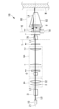
- FIG. 1 is a front view showing a schematic configuration of a laser processing apparatus according to an embodiment of the present disclosure.
- 1 is a plan view showing a schematic configuration of a laser processing apparatus according to an embodiment of the present disclosure.
- FIG. 2 is a perspective view showing a quarter wavelength plate.
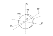
- FIG. 3 is a diagram showing the relationship between the direction of the optical axis of a quarter-wave plate and the polarization direction of laser light.
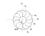
- FIG. 3 is a diagram showing an example of processing a workpiece by converting linearly polarized light into circularly polarized light.
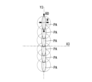
- FIG. 3 is a diagram showing an example of processing a workpiece without converting the polarization direction of linearly polarized light.
- FIG. 1 is a front view showing a schematic configuration of a laser processing apparatus 100 according to this embodiment.
- FIG. 2 is a plan view showing a schematic configuration of the laser processing apparatus 100 according to the present embodiment.
- the laser processing apparatus 100 of this embodiment includes an irradiation section 10, a linear polarizer 20, a reduction optical system 30, a KTN crystal element (second crystal element) 40, and a voltage application section ( second voltage application section) 45, plano-concave lens 47, connection optical system 50, half-wave plate 60, KTN crystal element (first crystal element) 70, voltage application section (first voltage application section) 75 , an emission section 80 , a quarter wavelength plate 90 , an adjustment mechanism 91 , and a control section 95 .
- the irradiation unit 10 is a device that irradiates a randomly polarized laser beam L0 toward a workpiece W such as a metal plate along an axis (first axis) Z1.
- the irradiation unit 10 irradiates a laser beam L0 having an output of 20 W or more and 1000 W or less.
- the linear polarizer 20 is an element into which the laser beam L0 irradiated by the irradiation unit 10 is incident.
- the linear polarizer 20 polarizes linearly polarized light (second linearly polarized light) that is a component of the polarization direction (second polarization direction) along the X2-Z1 plane formed by the axis Z1 of the laser beam L0 and the axis X2 perpendicular to the axis Z1. )
- L2 is transmitted along the axis Z1.
- the polarization direction of the linearly polarized light L2 is 90 degrees different from the polarization direction of the linearly polarized light L1, which will be described later.
- linear polarizer 20 emits linearly polarized light L3, which is a component whose polarization direction is 90 degrees different from that of the linearly polarized light L2, along the axis (second axis) X2.
- the linear polarizer 20 is made of, for example, calcite or quartz.
- the reduction optical system 30 is an optical system that narrows down the beam diameter of the linearly polarized light L2 that has passed through the linear polarizer 20 and emits it toward the KTN crystal element 40 along the axis Z1.
- the reduction optical system 30 has a first biconvex lens 31 and a second biconvex lens 32 arranged along the axis Z1.
- the KTN crystal element 40 is an oxide crystal made of potassium (K), tantalum (Ta), and niobium (Nb).
- the KTN crystal element 40 is an electro-optic crystal that can adjust the emission direction of linearly polarized light in a fixed polarization direction in accordance with the voltage applied by the voltage application section 45.
- a KTN crystal element is used as an example of the electro-optic crystal, but lithium niobate or lithium tantalate can also be used.
- the KTN crystal element 40 shown in FIG. 1 is arranged so that the output direction of the linearly polarized light L2 in the polarization direction along the X1-Z1 plane that has passed through the linear polarizer 20 can be adjusted.
- the linearly polarized light L2 that has passed through the linear polarizer 20 is incident on the KTN crystal element 40.
- the KTN crystal element 40 changes the emission direction (second emission direction) ⁇ x of the linearly polarized light L2, which is a component of the polarization direction along the X1-Z1 plane of the laser beam L0, with respect to the axis Z1 to the voltage applied by the voltage application unit 45. Adjust accordingly.
- the voltage application unit 45 is a device that applies voltage to the KTN crystal element 40.
- the voltage applying unit 45 adjusts the voltage applied to the KTN crystal element 40 so that the emission direction ⁇ x in which the KTN crystal element 40 emits the linearly polarized light L2 is adjusted to an arbitrary angle.
- the voltage application section 45 adjusts the voltage applied to the KTN crystal element 40 according to a control signal transmitted from the control section 95.
- the frequency of the voltage output by the voltage application unit 45 is set, for example, to 1 kHz or more and 1 MHz or less.
- the connecting optical system 50 is an optical system that guides the linearly polarized light L2 emitted from the KTN crystal element 40 and passed through the plano-concave lens 47 to the half-wave plate 60.
- the connecting optical system 50 includes a plano-convex lens 51 and a plano-convex lens 52, the convex portions of which are arranged to face each other.
- the half-wave plate 60 changes the polarization direction of the linearly polarized light L2 that passes through the KTN crystal element 40 and is emitted from the connection optical system 50 into a polarization direction that is 90 degrees different from the polarization direction along the X1-Z1 plane (a first polarization direction).
- ) is a member that guides the linearly polarized light (first linearly polarized light) L1 to the KTN crystal element 70.
- the half-wave plate 60 changes the polarization direction of the linearly polarized light L2 to a polarization direction that is 90 degrees different from the polarization direction along the X1-Z1 plane by giving the incident linearly polarized light L2 a phase difference of 180 degrees corresponding to a half wavelength. Convert.
- the half-wave plate 60 changes the polarization direction of the linearly polarized light L2 by 90 degrees because the KTN crystal element 70 changes the polarization direction of the linearly polarized light L1 along the Y1-Z1 plane perpendicular to the X1-Z1 plane with respect to the axis Z1.
- This is to adjust the emission direction (first emission direction) ⁇ y according to the voltage applied by the voltage application section 75.
- the emission direction ⁇ x adjusted by the KTN crystal element 40 and the emission direction ⁇ y adjusted by the KTN crystal element 70 can be adjusted to an arbitrary position on the two-dimensional plane. The position can be adjusted.
- the KTN crystal element 70 is an oxide crystal made of potassium (K), tantalum (Ta), and niobium (Nb).
- the KTN crystal element 70 is an electro-optic crystal that can adjust the emission direction of linearly polarized light in a fixed polarization direction in accordance with the voltage applied by the voltage application section 75.
- a KTN crystal element is used as an example of the electro-optic crystal, but lithium niobate or lithium tantalate can also be used.
- the KTN crystal element 70 shown in FIG. 1 is arranged so that the output direction of linearly polarized light L1 having a polarization direction along the Y1-Z1 plane that has passed through the half-wave plate 60 can be adjusted.
- the linearly polarized light L1 that has passed through the half-wave plate 60 is incident on the KTN crystal element 70.
- the KTN crystal element 70 adjusts the emission direction (first emission direction) ⁇ y of the linearly polarized light L1 having a polarization direction along the Y1-Z1 plane with respect to the axis Z1 according to the voltage applied by the voltage application unit 75.
- the voltage application unit 75 is a device that applies a voltage to the KTN crystal element 70.
- the voltage applying unit 75 adjusts the voltage applied to the KTN crystal element 70 so that the emission direction ⁇ y in which the KTN crystal element 70 emits the linearly polarized light L1 is adjusted to an arbitrary angle.
- the voltage application section 75 adjusts the voltage applied to the KTN crystal element 70 according to a control signal transmitted from the control section 95.
- the frequency of the voltage output by the voltage applying section 75 is set to, for example, 1 kHz or more and 1 MHz or less.
- the output unit 80 is a device that outputs linearly polarized light L1, whose output direction ⁇ x is adjusted by the KTN crystal element 40 and whose output direction ⁇ y is adjusted by the KTN crystal element 70, to the workpiece W.
- the output section 80 includes a condensing lens 81 that is a biconvex lens and a gas nozzle 82 .
- the condensing lens 81 is a lens for condensing the linearly polarized light L1 emitted from the KTN crystal element 70 and passing through the plano-concave lens 77 near the axis Z1.
- the gas nozzle 82 is a truncated conical tube extending along the axis Z1, and an inert gas (for example, nitrogen gas) is injected from the condensing lens 81 toward the workpiece W along the axis Z1. circulate. By injecting inert gas toward the workpiece W using the gas nozzle 82, the workpiece W melted by the laser beam can be blown away.
- the quarter-wave plate 90 is a member disposed on the axis Z1 between the KTN crystal element 70 and the emission section 80.
- the quarter-wave plate 90 is an optical member capable of converting linearly polarized light into circularly polarized light.
- the quarter-wave plate 90 is arranged to convert the linearly polarized light L1 incident from the KTN crystal element 70 into circularly polarized light L4.
- the adjustment mechanism 91 is a mechanism that adjusts the direction of the optical axis OP of the quarter-wave plate 90 around the axis Z1.
- the adjustment mechanism 91 rotates the quarter-wave plate 90 around the axis Z1 using an electric motor (not shown) that is driven in response to a control signal from the control unit 95. Adjust the direction of the optical axis OP of the /4 wavelength plate 90.
- FIG. 3 is a perspective view showing the quarter-wave plate 90.
- FIG. 4 is a diagram showing the relationship between the direction of the optical axis OP of the quarter-wave plate 90 and the polarization direction of laser light.
- the quarter-wave plate 90 is arranged so that the incident surface 90a on which the linearly polarized light L1 emitted from the KTN crystal element 70 is incident coincides with the X3-Y3 plane.
- the axis X3 is an axis perpendicular to the axis Z1.
- the axis Y3 is an axis perpendicular to both the axis Z1 and the axis X3.
- the optical axis OP is inclined at an angle ⁇ with respect to the axis Y3 in the X3-Y3 plane.
- the angle ⁇ is adjusted by an adjustment mechanism 91.
- the adjustment mechanism 91 adjusts the direction of the optical axis OP of the quarter-wave plate 90 around the axis Z1 so that the angle ⁇ is 45 degrees.
- the polarization direction L2p of the linearly polarized light L2, which is the laser light from passing through the linear polarizer 20 to entering the half-wave plate 60 is the same as the axis X3 (axis X1, X2). axis).
- the polarization direction L1p of the linearly polarized light L1 which is the laser light from passing through the half-wave plate 60 to entering the quarter-wave plate 90, is a direction along the axis Y3 (the axis in the same direction as the axis Y1). becomes.
- the optical axis OP of the quarter-wave plate 90 is inclined at an angle ⁇ with respect to the axis Y3.
- the adjustment mechanism 91 adjusts the direction of the optical axis OP of the quarter-wave plate 90 around the axis Z1 so that the angle ⁇ is 45 degrees.
- the quarter-wave plate 90 arranged so that the angle ⁇ is 45 degrees converts the linearly polarized light L1 into the circularly polarized light L4.
- the polarization direction L4p of the circularly polarized light L4 is a direction that periodically revolves around the axis Z1.
- the adjustment mechanism 91 adjusts the quarter-wave plate 90 around the axis Z1 so that when the linearly polarized light L1 passes through the quarter-wave plate 90 without changing the polarization direction, the angle ⁇ becomes 0 degrees or 90 degrees. Adjust the direction of the optical axis OP.
- the quarter-wave plate 90 arranged so that the angle ⁇ is 0 degrees or 90 degrees allows the linearly polarized light L1 to pass through without changing its polarization direction.
- FIG. 5 is a diagram showing an example of processing the workpiece W by converting the linearly polarized light L1 into the circularly polarized light L4.
- FIG. 6 is a diagram showing an example of processing the workpiece W without converting the polarization direction of the linearly polarized light L1.
- the processing area PA indicates a melted portion formed on the workpiece W such as a metal plate during the on-state period in which the laser beam is irradiated from the irradiation unit 10.
- the processing area PA has a substantially perfect circular shape with the beam diameter BD of the laser light. This is because the polarization direction of the circularly polarized light L4 emitted from the emitting section 80 changes periodically, and the amount of processing in the area irradiated with the laser beam (all areas within the beam diameter BD) is made uniform. be. Since the amount of machining in all areas within the beam diameter BD is made uniform, it is suitable for machining each area of the circular machining shape PS shown in FIG. 5 equally to make a circular hole in the workpiece W. ing.
- the processing area PA when processing the workpiece W without converting the polarization direction of the linearly polarized light L1, the processing area PA has a width where the beam diameter BD of the laser light is shorter than the beam diameter BD on the long axis. It has an elliptical shape with W as the short axis. This is because the polarization direction L1p of the linearly polarized light L1 emitted from the emission unit 80 is fixed, and the amount of processing in the area irradiated with the laser beam (all areas within the beam diameter BD) is along the polarization direction L1p. This is because the number increases in the direction (direction along the axis Y3). Since the amount of processing in the region irradiated with the laser beam increases in the direction along the polarization direction L1p, it is suitable for cutting processing, etc. in which processing is performed linearly along the polarization direction L1p.
- the adjustment mechanism 91 converts the linearly polarized light L1 into circularly polarized light L4 by setting the angle ⁇ to 45 degrees, or changes the polarization direction of the linearly polarized light L1 by setting the angle ⁇ to 0 degrees or 90 degrees.
- the adjustment mechanism 91 may set the angle ⁇ to any angle greater than 0 and less than 45 degrees, or greater than 45 degrees and less than 90 degrees.
- the width W shown in FIG. 6 can be changed. By setting the width W to an appropriate length, an appropriate processing area PA can be formed on the workpiece W according to the processing desired to be performed on the workpiece W.
- the control section 95 is a device that transmits control signals to the voltage application section 45 and the voltage application section 75.
- the control unit 95 transmits a control signal for adjusting the voltage applied to the KTN crystal element 40 by the voltage application unit 45 to the voltage application unit 45, and adjusts the voltage applied to the KTN crystal element 70 by the voltage application unit 75.
- a control signal for this purpose is transmitted to the voltage application section 75.
- the laser processing apparatus 100 of this embodiment described above has the following functions and effects.
- the laser beam irradiated from the irradiation unit 10 is incident on the KTN crystal element 70, and the laser beam is applied to the axis Z1 and perpendicular to the axis Z1 according to the voltage applied by the voltage application unit 75.
- the output direction ⁇ y of the linearly polarized light L1 in the polarization direction L1p along the plane formed by the axis Y1 is adjusted with respect to the axis Z1.
- the linearly polarized light L1 with the polarization direction L1p whose output direction ⁇ y has been adjusted is outputted to the workpiece W by the output unit 80.
- the quarter-wave plate 90 is arranged between the KTN crystal element 70 and the emission section 80, the direction of the optical axis OP of the quarter-wave plate 90 is adjusted.
- the quarter-wave plate 90 can convert the polarization direction L1p of the linearly polarized light L1 into circularly polarized light L4. Therefore, the polarization direction of the laser beam emitted from the emission section 80 changes periodically, and the processing amount in all regions within the beam diameter BD of the laser beam is made uniform.
- the laser processing apparatus 100 of the present embodiment high-speed processing is performed by adjusting the emission direction ⁇ y of the laser light according to the voltage, and uniform processing is performed in all areas within the beam diameter BD of the laser light. It becomes possible to do so.
- the direction of the optical axis OP of the quarter-wave plate 90 around the axis Z1 is adjusted by the adjustment mechanism 91 to convert the linearly polarized light L1 into the circularly polarized light L4. This makes it possible to uniformly process all regions within the beam diameter BD of the laser beam.
- the polarization of the linearly polarized light L1 within the beam diameter BD can be adjusted.
- the amount of processing in the region in the direction L1p can be made larger than the amount of processing in other regions, and for example, the amount of processing when processing by moving the laser beam linearly along the polarization direction L1p can be increased.
- the linear polarizer 20 by arranging the linear polarizer 20, a component of the randomly polarized laser light irradiated from the irradiation unit 10 in the polarization direction L2p that is 90 degrees different from the polarization direction L1p.
- the linearly polarized light L2 is incident on the KTN crystal element 40
- a component of the laser beam in a direction different from the polarization direction L2p is not incident on the KTN crystal element 40.
- a component of the laser beam in a direction different from the polarization direction L2p is a component whose emission direction ⁇ x cannot be adjusted by the KTN crystal element 40.
- the amount of the laser beam incident on the KTN crystal element 40 is suppressed, and the emission direction ⁇ x of the laser beam due to the temperature rise of the KTN crystal element 40 is reduced. Fluctuations can be suppressed.
- the linearly polarized light L2 that has passed through the KTN crystal element 40 changes to the polarization direction L1p, which is 90 degrees different from the polarization direction L2p when passing through the half-wave plate 60.
- Linearly polarized light L1 polarized in the polarization direction L1p is incident on the KTN crystal element 70.
- the KTN crystal element 70 adjusts the emission direction ⁇ y with respect to the axis Z1 according to the voltage applied by the voltage application section 75.
- the linearly polarized light L1 whose emission direction ⁇ y has been adjusted is emitted to the workpiece W by the emission unit 80.
- the laser beam can be irradiated to an arbitrary irradiation position in a two-dimensional direction. Can be adjusted.
- a laser processing apparatus (100) includes an irradiation unit (10) that irradiates a laser beam (L0) toward a workpiece (W) along a first axis (Z1);
- the laser beam irradiated from the irradiation unit is incident, and the laser beam is polarized in a first polarization direction along a plane formed by the first axis and a second axis (Y1) perpendicular to the first axis.
- a first crystal element (70) that adjusts a first emission direction ( ⁇ y) with respect to one axis according to an applied voltage
- a first voltage application section (75) that applies a voltage to the first crystal element
- an emitting section (80) that emits the laser beam, the first emitting direction of which has been adjusted by a first crystal element, to the workpiece (W); and an emitting section (80) disposed between the first crystal element and the emitting section. and a quarter wavelength plate (90).
- the laser beam irradiated from the irradiation section is incident on the first crystal element, and the laser beam is applied to the first axis according to the voltage applied by the first voltage application section.
- the first emission direction of the laser light in the first polarization direction along the plane formed by the orthogonal second axes with respect to the first axis is adjusted.
- the laser beam in the first polarization direction whose first emission direction has been adjusted is emitted to the workpiece by the emission section.
- the quarter-wave plate is disposed between the first crystal element and the emission section, by adjusting the direction of the crystal optical axis of the quarter-wave plate, The first polarization direction of the laser beam can be converted into circularly polarized light using a quarter-wave plate. Therefore, the polarization direction of the laser beam emitted from the emission section changes periodically, and the processing amount in all regions within the beam diameter of the laser beam is made uniform. Therefore, according to the laser processing apparatus according to the present disclosure, it is possible to perform high-speed processing by adjusting the emission direction of the laser light according to the voltage, and to perform uniform processing in all areas within the beam diameter of the laser light. It becomes possible.
- the quarter-wave plate converts first linearly polarized light (L1), which is a component in the first polarization direction of the laser beam, into circularly polarized light (L1). L4).
- L1 first linearly polarized light
- L4 circularly polarized light
- a laser processing apparatus includes an adjustment mechanism (91) that adjusts the direction of the optical axis (OP) of the quarter-wave plate around the first axis. Equipped with.
- the laser processing apparatus by adjusting the direction of the optical axis of the quarter-wave plate around the first axis using the adjustment mechanism and converting the first linearly polarized light into circularly polarized light, , it becomes possible to uniformly process all areas within the beam diameter of the laser beam.
- the polarization direction of the first linearly polarized light within the beam diameter can be adjusted.
- the amount of processing in the area can be made larger than the amount of processing in other areas, and for example, the amount of processing when processing by moving the laser beam linearly along the polarization direction can be increased.
- the randomly polarized laser beam irradiated by the irradiation unit is incident, and the first laser beam of the laser beam is incident.
- a linear polarizer (20) that transmits second linearly polarized light (L2), which is a component in a second polarization direction that is 90 degrees different from the polarization direction, along the first axis (Z1); a second crystal element (40) into which the second linearly polarized light is incident and which adjusts a second exit direction ( ⁇ x) of the second linearly polarized light with respect to the first axis according to an applied voltage; a second voltage applying section (45) that applies a voltage to the second crystal element; and a second voltage applying section (45) that changes the second polarization direction of the second linearly polarized light that has passed through the second crystal element to the first polarization direction and guides the second linearly polarized light to the first crystal element.
- the second linearly polarized light which is a component in the second polarization direction that is 90 degrees different from the first polarization direction, of the randomly polarized laser light irradiated from the irradiation section is
- the laser beam is incident on the second crystal element, a component of the laser beam in a direction different from the second polarization direction is not incident on the second crystal element.
- a component of the laser beam in a direction different from the second polarization direction is a component whose second emission direction cannot be adjusted by the second crystal element.
- the amount of laser light incident on the second crystal element is suppressed, and the output direction of the laser beam due to the temperature rise of the second crystal element is suppressed. Fluctuations can be suppressed.
- the second linearly polarized light that has passed through the second crystal element has a polarization direction different from the second polarization direction by 90 degrees when passing through the half-wave plate.
- the polarization direction is changed, and first linearly polarized light polarized in the first polarization direction is incident on the first crystal element.
- the first crystal element adjusts the first emission direction with respect to the first axis according to the voltage applied by the first voltage application section.
- the first linearly polarized light whose first emission direction has been adjusted is emitted to the workpiece by the emission section.
- the laser beam can be adjusted in any two-dimensional direction. It can be adjusted so that the irradiation position is irradiated.
Landscapes
- Physics & Mathematics (AREA)
- Optics & Photonics (AREA)
- Engineering & Computer Science (AREA)
- Plasma & Fusion (AREA)
- Mechanical Engineering (AREA)
- Laser Beam Processing (AREA)
Abstract
被加工物(W)に向けてレーザ光(L0)を軸線(Z1)に沿って照射する照射部(10)と、照射部(10)から照射されたレーザ光(L0)が入射するとともに軸線(Z1)および軸線(Z1)に直交する軸線(Y1)により形成される平面に沿った偏光方向のレーザ光の軸線(Z1)に対する出射方向(θy)を印加される電圧に応じて調整するKTN結晶素子(70)と、KTN結晶素子(70)に電圧を印加する電圧印加部と、KTN結晶素子(70)により出射方向(θy)が調整されたレーザ光を被加工物(W)に出射する出射部(80)と、KTN結晶素子(70)と出射部(80)との間に配置される1/4波長板(90)と、を備えるレーザ加工装置(100)を提供する。
Description
本開示は、レーザ加工装置に関するものである。
従来、100kHz~1MHz程度の発振周波数を有する短パルスレーザ発振器などのレーザ発振器が知られている。一方、レーザ光を走査するために広く用いられるガルバノ光学系は、機械的にミラーを振動させるものであり、走査周波数が最大でも1kHz程であるためレーザ発振器の発振周波数に比べて1~2桁周波数が低い。
そして、電圧制御によってレーザ光の走査を行うことが可能な電気光学材料であるKTN結晶を利用した光ビームスキャナが提案されている(特許文献1)。特許文献1に開示される光ビームスキャナは、機械的にミラーを振動させるものではなく電圧制御によりレーザ光の走査を行うため、200kHzを超える高速な動作を実現することが可能となっている。特許文献1に開示される光ビームスキャナを用いて電圧制御によりレーザ光の走査を行うことで高速走査による高速加工が可能となる。
しかしながら、特許文献1に開示される光ビームスキャナは、所定の偏光方向の直線偏光成分のみを走査するものであり、光ビームスキャナが走査するレーザ光は直線偏光成分のみを有するものとなる。そのため、例えば、レーザ光のビーム径内の全ての領域に均一の加工を行いたい場合など、直線偏光成分のみのレーザ光では所望の加工を行うことができない可能性がある。
本開示は、このような事情に鑑みてなされたものであって、レーザ光による高速加工を行うとともにレーザ光のビーム径内の全ての領域に均一の加工を行うことが可能なレーザ加工装置を提供することを目的とする。
本開示の一態様に係るレーザ加工装置は、被加工物に向けてレーザ光を第1軸線に沿って照射する照射部と、前記照射部から照射された前記レーザ光が入射するとともに前記第1軸線および前記第1軸線に直交する第2軸線により形成される平面に沿った第1偏光方向の前記レーザ光の前記第1軸線に対する第1出射方向を印加される電圧に応じて調整する第1結晶素子と、前記第1結晶素子に電圧を印加する第1電圧印加部と、前記第1結晶素子により前記第1出射方向が調整された前記レーザ光を前記被加工物に出射する出射部と、前記第1結晶素子と前記出射部との間に配置される1/4波長板と、を備える。
本開示によれば、レーザ光による高速加工を行うとともにレーザ光のビーム径内の全ての領域に均一の加工を行うことが可能なレーザ加工装置を提供することを目的とする。
以下、本開示の一実施形態に係るレーザ加工装置100について、図面を参照して説明する。図1は、本実施形態に係るレーザ加工装置100の概略構成を示す正面図である。図2は、本実施形態に係るレーザ加工装置100の概略構成を示す平面図である。
図1に示すように、本実施形態のレーザ加工装置100は、照射部10と、直線偏光子20と、縮小光学系30と、KTN結晶素子(第2結晶素子)40と、電圧印加部(第2電圧印加部)45と、平凹レンズ47と、接続用光学系50と、半波長板60と、KTN結晶素子(第1結晶素子)70と、電圧印加部(第1電圧印加部)75と、出射部80と、1/4波長板90と、調整機構91と、制御部95と、を備える。
照射部10は、金属板等の被加工物Wに向けてランダム偏光のレーザ光L0を軸線(第1軸線)Z1に沿って照射する装置である。照射部10は、20W以上かつ1000W以下の出力を有するレーザ光L0を照射する。
直線偏光子20は、照射部10により照射されたレーザ光L0が入射される素子である。直線偏光子20は、レーザ光L0の軸線Z1および軸線Z1に直交する軸線X2により形成されるX2-Z1平面に沿った偏光方向(第2偏光方向)の成分である直線偏光(第2直線偏光)L2を軸線Z1に沿って透過させる。直線偏光L2の偏光方向は、後述する直線偏光L1の偏光方向と偏光方向が90度異なる。
また、直線偏光子20は、直線偏光L2の偏光方向と90度異なる偏光方向の成分である直線偏光L3を軸線(第2軸線)X2に沿って出射する。直線偏光子20は、例えば、方解石や水晶により形成されている。
縮小光学系30は、直線偏光子20を透過した直線偏光L2のビーム径を絞り、KTN結晶素子40に向けて軸線Z1に沿って出射する光学系である。縮小光学系30は、第1両凸レンズ31および第2両凸レンズ32を軸線Z1に沿って配置したものである。
KTN結晶素子40は、カリウム(K),タンタル(Ta),ニオブ(Nb)からなる酸化物結晶である。KTN結晶素子40は、電圧印加部45により印加される電圧に応じて、一定の偏光方向の直線偏光の出射方向を調整可能な電気光学結晶である。ここでは、電気光学結晶としてKTN結晶素子を例として出しているが、ニオブ酸リチウムやタンタル酸リチウムでも適用可能である。
図1に示すKTN結晶素子40は、直線偏光子20を通過したX1-Z1平面に沿った偏光方向の直線偏光L2の出射方向を調整可能とするように配置されている。KTN結晶素子40には、直線偏光子20を通過した直線偏光L2が入射する。KTN結晶素子40は、レーザ光L0のX1-Z1平面に沿った偏光方向の成分である直線偏光L2の軸線Z1に対する出射方向(第2出射方向)θxを電圧印加部45により印加される電圧に応じて調整する。
電圧印加部45は、KTN結晶素子40に電圧を印加する装置である。電圧印加部45は、KTN結晶素子40が直線偏光L2を出射する出射方向θxを任意の角度に調整するように、KTN結晶素子40に印加する電圧を調整する。電圧印加部45は、制御部95から伝達される制御信号に応じてKTN結晶素子40に印加する電圧を調整する。電圧印加部45が出力する電圧の周波数は、例えば、1kHz以上かつ1MHz以下に設定される。
接続用光学系50は、KTN結晶素子40から出射されて平凹レンズ47を通過した直線偏光L2を半波長板60に導く光学系である。接続用光学系50は、凸部分が対向して配置される平凸レンズ51および平凸レンズ52を有する。
半波長板60は、KTN結晶素子40を通過して接続用光学系50から出射される直線偏光L2の偏光方向をX1-Z1平面に沿った偏光方向と90度異なる偏光方向(第1偏光方向)に変えた直線偏光(第1直線偏光)L1をKTN結晶素子70へ導く部材である。半波長板60は、入射される直線偏光L2に半波長分の180度の位相差を与えることにより、直線偏光L2の偏光方向をX1-Z1平面に沿った偏光方向から90度異なる偏光方向に変換する。
半波長板60で直線偏光L2の偏光方向を90度変えているのは、KTN結晶素子70においてX1-Z1平面に直交するY1-Z1平面に沿った偏光方向を有する直線偏光L1の軸線Z1に対する出射方向(第1出射方向)θyを電圧印加部75により印加される電圧に応じて調整するためである。KTN結晶素子40が調整する出射方向θxとKTN結晶素子70が調整する出射方向θyとを90度異ならせることにより、直線偏光L1の被加工物Wへの照射位置を2次元平面上の任意の位置に調整することができる。
KTN結晶素子70は、カリウム(K),タンタル(Ta),ニオブ(Nb)からなる酸化物結晶である。KTN結晶素子70は、電圧印加部75により印加される電圧に応じて、一定の偏光方向の直線偏光の出射方向を調整可能な電気光学結晶である。ここでは、電気光学結晶としてKTN結晶素子を例として出しているが、ニオブ酸リチウムやタンタル酸リチウムでも適用可能である。
図1に示すKTN結晶素子70は、半波長板60を通過したY1-Z1平面に沿った偏光方向を有する直線偏光L1の出射方向を調整可能とするように配置されている。KTN結晶素子70には、半波長板60を通過した直線偏光L1が入射する。KTN結晶素子70は、Y1-Z1平面に沿った偏光方向を有する直線偏光L1の軸線Z1に対する出射方向(第1出射方向)θyを電圧印加部75により印加される電圧に応じて調整する。
電圧印加部75は、KTN結晶素子70に電圧を印加する装置である。電圧印加部75は、KTN結晶素子70が直線偏光L1を出射する出射方向θyを任意の角度に調整するように、KTN結晶素子70に印加する電圧を調整する。電圧印加部75は、制御部95から伝達される制御信号に応じてKTN結晶素子70に印加する電圧を調整する。電圧印加部75が出力する電圧の周波数は、例えば、1kHz以上かつ1MHz以下に設定される。
出射部80は、KTN結晶素子40により出射方向θxが調整され、かつKTN結晶素子70により出射方向θyが調整された直線偏光L1を被加工物Wに出射する装置である。出射部80は、両凸レンズである集光レンズ81と、ガスノズル82とを有する。
集光レンズ81は、KTN結晶素子70から出射されて平凹レンズ77を通過した直線偏光L1を軸線Z1の近傍に集光するためのレンズである。ガスノズル82は、軸線Z1に沿って延びる円錐台状の筒であり、軸線Z1に沿って集光レンズ81から被加工物Wに向けて噴射される不活性ガス(例えば、窒素ガス)が内部を流通する。ガスノズル82により被加工物Wに向けて不活性ガスを噴射することにより、レーザ光により溶融した被加工物Wを吹き飛ばすことができる。
1/4波長板90は、KTN結晶素子70と出射部80との間の軸線Z1上に配置される部材である。1/4波長板90は、直線偏光を円偏光に変換することが可能な光学部材である。1/4波長板90は、KTN結晶素子70から入射される直線偏光L1を円偏光L4に変換するように配置されている。
調整機構91は、軸線Z1回りの1/4波長板90の光学軸OPの方向を調整する機構である。調整機構91は、例えば、制御部95からの制御信号に応答して駆動する電動モータ(図示略)を用いて1/4波長板90を軸線Z1回りに回転させることにより、軸線Z1回りの1/4波長板90の光学軸OPの方向を調整する。
ここで、図3および図4を参照して、1/4波長板90の光学軸OPとレーザ光の偏光方向との関係について説明する。図3は、1/4波長板90を示す斜視図である。図4は、1/4波長板90の光学軸OPの方向と、レーザ光の偏光方向との関係を示す図である。
図3に示すように、1/4波長板90は、KTN結晶素子70から出射した直線偏光L1が入射する入射面90aがX3-Y3平面と一致するように配置される。軸線X3は、軸線Z1に直交する軸線である。軸線Y3は、軸線Z1と軸線X3の双方に直交する軸線である。図3に示すように、光学軸OPは、X3-Y3平面において、軸線Y3に対して角度αだけ傾斜して配置される。角度αは、調整機構91により調整される。調整機構91は、角度αが45度となるように、軸線Z1回りの1/4波長板90の光学軸OPの方向を調整する。
図4に示すように、直線偏光子20を通過してから半波長板60に入射するまでのレーザ光である直線偏光L2の偏光方向L2pは、軸線X3(軸線X1,軸線X2と同じ方向の軸線)に沿った方向となる。一方、半波長板60を通過してから1/4波長板90に入射するまでのレーザ光である直線偏光L1の偏光方向L1pは、軸線Y3(軸線Y1と同じ方向の軸線)に沿った方向となる。X3-Y3平面において、1/4波長板90の光学軸OPは、軸線Y3に対して角度αだけ傾斜して配置される。
調整機構91は、直線偏光L1を円偏光L4に変換する場合、角度αが45度となるように、軸線Z1回りの1/4波長板90の光学軸OPの方向を調整する。角度αが45度となるように配置された1/4波長板90は、直線偏光L1を円偏光L4に変換する。図4に示すように、円偏光L4の偏光方向L4pは、軸線Z1回りに周期的に周回する方向となる。
調整機構91は、直線偏光L1の偏光方向を変換せずに1/4波長板90を通過させる場合、角度αが0度または90度となるように、軸線Z1回りの1/4波長板90の光学軸OPの方向を調整する。角度αが0度または90度となるように配置された1/4波長板90は、直線偏光L1の偏光方向を変換せずに通過させる。
次に、図5および図6を参照して、直線偏光L1を円偏光L4に変換して被加工物Wを加工する場合と、直線偏光L1の偏光方向を変換せずに被加工物Wを加工する場合について説明する。図5は、直線偏光L1を円偏光L4に変換して被加工物Wを加工する例を示す図である。図6は、直線偏光L1の偏光方向を変換せずに被加工物Wを加工する例を示す図である。図5および図6において、加工領域PAは、照射部10からレーザ光が照射されるオン状態の期間に金属板等の被加工物Wに形成される溶融部分を示す。
図5に示すように、直線偏光L1を円偏光L4に変換して被加工物Wを加工する場合、加工領域PAはレーザ光のビーム径BDの略真円形状となる。これは、出射部80から出射される円偏光L4の偏光方向が周期的に変化し、レーザ光が照射される領域(ビーム径BD内の全ての領域)における加工量が均一化されるからである。ビーム径BD内の全ての領域における加工量が均一化されるため、図5に示す円形の加工形状PSの各領域を均等に加工して被加工物Wに円形の穴を空ける加工等に適している。
一方、図6に示すように、直線偏光L1の偏光方向を変換せずに被加工物Wを加工する場合、加工領域PAはレーザ光のビーム径BDが長軸でビーム径BDよりも短い幅Wが短軸の楕円形状となる。これは、出射部80から出射される直線偏光L1の偏光方向L1pが固定されており、レーザ光が照射される領域(ビーム径BD内の全ての領域)における加工量が偏光方向L1pに沿った方向(軸線Y3に沿った方向)で多くなるからである。レーザ光が照射される領域における加工量が偏光方向L1pに沿った方向で多くなるため、偏光方向L1pに沿って直線状に加工する切断加工等に適している。
以上において、調整機構91は、角度αを45度となるようにして直線偏光L1を円偏光L4に変換するか、角度αを0度または90度となるようにして直線偏光L1の偏光方向を変換せずに1/4波長板90を通過させるかのいずれかを実行するものとしたが、他の態様であってもよい。例えば、調整機構91は、角度αを0より大きく45度未満の任意の角度、または45度より大きく90度未満の任意の角度に設定しても良い。この場合、図6に示す幅Wを変化させることができる。幅Wを適切な長さに設定することで、被加工物Wに行いたい加工に応じた適切な加工領域PAを被加工物Wに形成することができる。
制御部95は、電圧印加部45および電圧印加部75に制御信号を伝達する装置である。制御部95は、電圧印加部45がKTN結晶素子40に印加する電圧を調整するための制御信号を電圧印加部45に伝達し、電圧印加部75がKTN結晶素子70に印加する電圧を調整するための制御信号を電圧印加部75に伝達する。
以上説明した本実施形態のレーザ加工装置100は、以下の作用及び効果を奏する。
本実施形態のレーザ加工装置100によれば、照射部10から照射されたレーザ光がKTN結晶素子70に入射され、電圧印加部75により印加される電圧に応じて、軸線Z1および軸線Z1に直交する軸線Y1により形成される平面に沿った偏光方向L1pの直線偏光L1の軸線Z1に対する出射方向θyが調整される。出射方向θyが調整された偏光方向L1pの直線偏光L1は、出射部80により被加工物Wに出射される。
本実施形態のレーザ加工装置100によれば、照射部10から照射されたレーザ光がKTN結晶素子70に入射され、電圧印加部75により印加される電圧に応じて、軸線Z1および軸線Z1に直交する軸線Y1により形成される平面に沿った偏光方向L1pの直線偏光L1の軸線Z1に対する出射方向θyが調整される。出射方向θyが調整された偏光方向L1pの直線偏光L1は、出射部80により被加工物Wに出射される。
本実施形態のレーザ加工装置100によれば、KTN結晶素子70と出射部80との間に1/4波長板90が配置されるため、1/4波長板90の光学軸OPの方向を調整することにより、1/4波長板90で直線偏光L1の偏光方向L1pを円偏光L4に変換することができる。そのため、出射部80から出射されるレーザ光の偏光方向が周期的に変化し、レーザ光のビーム径BD内の全ての領域における加工量が均一化される。したがって、本実施形態のレーザ加工装置100によれば、電圧に応じてレーザ光の出射方向θyを調整することによる高速加工を行うとともにレーザ光のビーム径BD内の全ての領域に均一の加工を行うことが可能となる。
また、本実施形態のレーザ加工装置100によれば、調整機構91により軸線Z1回りの1/4波長板90の光学軸OPの方向を調整して、直線偏光L1を円偏光L4に変換することにより、レーザ光のビーム径BD内の全ての領域に均一の加工を行うことが可能となる。また、調整機構91により軸線Z1回りの1/4波長板90の光学軸OPの方向を調整して、直線偏光L1を直線偏光のまま通過させることにより、ビーム径BD内の直線偏光L1の偏光方向L1pの領域の加工量を他の領域の加工量よりも多くし、例えば、偏光方向L1pに沿って直線的にレーザ光を移動させて加工する際の加工量を多くすることができる。
本実施形態のレーザ加工装置100によれば、直線偏光子20を配置することにより、照射部10から照射されるランダム偏光のレーザ光のうち偏光方向L1pと90度異なる偏光方向L2pの成分である直線偏光L2がKTN結晶素子40に入射されるが、偏光方向L2pとは異なる方向のレーザ光の成分はKTN結晶素子40に入射されない。偏光方向L2pとは異なる方向のレーザ光の成分は、KTN結晶素子40による出射方向θxの調整ができない成分である。KTN結晶素子40に入射されるレーザ光を直線偏光L2に絞ることにより、KTN結晶素子40に入射されるレーザ光の光量を抑制し、KTN結晶素子40の温度上昇によるレーザ光の出射方向θxの変動を抑制することができる。
また、本実施形態のレーザ加工装置100によれば、KTN結晶素子40を通過した直線偏光L2は半波長板60を通過する際に偏光方向L2pと偏光方向が90度異なる偏光方向L1pに変わり、偏光方向L1pに偏光された直線偏光L1がKTN結晶素子70に入射される。KTN結晶素子70は、電圧印加部75により印加される電圧に応じて軸線Z1に対する出射方向θyを調整する。出射方向θyが調整された直線偏光L1は、出射部80により被加工物Wに出射される。本実施形態のレーザ加工装置によれば、直線偏光L1の出射方向θyと直線偏光L2の出射方向θxとを調整することにより、レーザ光が2次元方向の任意の照射位置へ照射されるように調整することができる。
以上説明した本実施形態に記載のレーザ加工装置は、例えば以下のように把握される。
本開示の第1態様に係るレーザ加工装置(100)は、被加工物(W)に向けてレーザ光(L0)を第1軸線(Z1)に沿って照射する照射部(10)と、前記照射部から照射された前記レーザ光が入射するとともに前記第1軸線および前記第1軸線に直交する第2軸線(Y1)により形成される平面に沿った第1偏光方向の前記レーザ光の前記第1軸線に対する第1出射方向(θy)を印加される電圧に応じて調整する第1結晶素子(70)と、前記第1結晶素子に電圧を印加する第1電圧印加部(75)と、前記第1結晶素子により前記第1出射方向が調整された前記レーザ光を前記被加工物(W)に出射する出射部(80)と、前記第1結晶素子と前記出射部との間に配置される1/4波長板(90)と、を備える。
本開示の第1態様に係るレーザ加工装置(100)は、被加工物(W)に向けてレーザ光(L0)を第1軸線(Z1)に沿って照射する照射部(10)と、前記照射部から照射された前記レーザ光が入射するとともに前記第1軸線および前記第1軸線に直交する第2軸線(Y1)により形成される平面に沿った第1偏光方向の前記レーザ光の前記第1軸線に対する第1出射方向(θy)を印加される電圧に応じて調整する第1結晶素子(70)と、前記第1結晶素子に電圧を印加する第1電圧印加部(75)と、前記第1結晶素子により前記第1出射方向が調整された前記レーザ光を前記被加工物(W)に出射する出射部(80)と、前記第1結晶素子と前記出射部との間に配置される1/4波長板(90)と、を備える。
本開示に係るレーザ加工装置によれば、照射部から照射されたレーザ光が第1結晶素子に入射され、第1電圧印加部により印加される電圧に応じて、第1軸線および第1軸線に直交する第2軸線により形成される平面に沿った第1偏光方向のレーザ光の第1軸線に対する第1出射方向が調整される。第1出射方向が調整された第1偏光方向のレーザ光は、出射部により被加工物に出射される。
本開示に係るレーザ加工装置によれば、第1結晶素子と出射部との間に1/4波長板が配置されるため、1/4波長板の結晶光学軸の方向を調整することにより、1/4波長板でレーザ光の第1偏光方向を円偏光に変換することができる。そのため、出射部から出射されるレーザ光の偏光方向が周期的に変化し、レーザ光のビーム径内の全ての領域における加工量が均一化される。したがって、本開示に係るレーザ加工装置によれば、電圧に応じてレーザ光の出射方向を調整することによる高速加工を行うとともにレーザ光のビーム径内の全ての領域に均一の加工を行うことが可能となる。
本開示の第2態様に係るレーザ加工装置は、第1態様において、前記1/4波長板が、前記レーザ光の前記第1偏光方向の成分である第1直線偏光(L1)を円偏光(L4)に変換するように配置されている。
本開示の第2態様に係るレーザ加工装置によれば、1/4波長板により第1直線偏光が円偏光に変換されるため、レーザ光のビーム径内の全ての領域に均一の加工を行うことが可能となる。
本開示の第2態様に係るレーザ加工装置によれば、1/4波長板により第1直線偏光が円偏光に変換されるため、レーザ光のビーム径内の全ての領域に均一の加工を行うことが可能となる。
本開示の第3態様に係るレーザ加工装置は、第1態様または第2態様において、前記第1軸線回りの前記1/4波長板の光学軸(OP)の方向を調整する調整機構(91)を備える。
本開示の第3態様に係るレーザ加工装置によれば、調整機構により第1軸線回りの1/4波長板の光学軸の方向を調整して、第1直線偏光を円偏光に変換することにより、レーザ光のビーム径内の全ての領域に均一の加工を行うことが可能となる。また、調整機構により第1軸線回りの1/4波長板の光学軸の方向を調整して、第1直線偏光を直線偏光のまま通過させることにより、ビーム径内の第1直線偏光の偏光方向の領域の加工量を他の領域の加工量よりも多くし、例えば、偏光方向に沿って直線的にレーザ光を移動させて加工する際の加工量を多くすることができる。
本開示の第3態様に係るレーザ加工装置によれば、調整機構により第1軸線回りの1/4波長板の光学軸の方向を調整して、第1直線偏光を円偏光に変換することにより、レーザ光のビーム径内の全ての領域に均一の加工を行うことが可能となる。また、調整機構により第1軸線回りの1/4波長板の光学軸の方向を調整して、第1直線偏光を直線偏光のまま通過させることにより、ビーム径内の第1直線偏光の偏光方向の領域の加工量を他の領域の加工量よりも多くし、例えば、偏光方向に沿って直線的にレーザ光を移動させて加工する際の加工量を多くすることができる。
本開示の第4態様に係るレーザ加工装置は、第1態様から第3態様のいずれかにおいて、前記照射部により照射されたランダム偏光の前記レーザ光が入射されるとともに前記レーザ光の前記第1偏光方向と90度異なる第2偏光方向の成分である第2直線偏光(L2)を前記第1軸線(Z1)に沿って透過させる直線偏光子(20)と、前記直線偏光子を通過した前記第2直線偏光が入射するとともに前記第2直線偏光の前記第1軸線に対する第2出射方向(θx)を印加される電圧に応じて調整する第2結晶素子(40)と、前記第2結晶素子に電圧を印加する第2電圧印加部(45)と、前記第2結晶素子を通過した前記第2直線偏光の前記第2偏光方向を前記第1偏光方向に変えて前記第1結晶素子へ導く半波長板(60)と、を備える。
本開示の第4態様に係るレーザ加工装置によれば、照射部から照射されるランダム偏光のレーザ光のうち第1偏光方向と90度異なる第2偏光方向の成分である第2直線偏光が第2結晶素子に入射されるが、第2偏光方向とは異なる方向のレーザ光の成分は第2結晶素子に入射されない。第2偏光方向とは異なる方向のレーザ光の成分は、第2結晶素子による第2出射方向の調整ができない成分である。第2結晶素子に入射されるレーザ光を第2直線偏光に絞ることにより、第2結晶素子に入射されるレーザ光の光量を抑制し、第2結晶素子の温度上昇によるレーザ光の出射方向の変動を抑制することができる。
また、本開示の第4態様に係るレーザ加工装置によれば、第2結晶素子を通過した第2直線偏光は半波長板を通過する際に第2偏光方向と偏光方向が90度異なる第1偏光方向に変わり、第1偏光方向に偏光された第1直線偏光が第1結晶素子に入射される。第1結晶素子は、第1電圧印加部により印加される電圧に応じて第1軸線に対する第1出射方向を調整する。第1出射方向が調整された第1直線偏光は、出射部により被加工物に出射される。本開示の第4態様に係るレーザ加工装置によれば、第1直線偏光の第1出射方向と第2直線偏光の第2出射方向とを調整することにより、レーザ光が2次元方向の任意の照射位置へ照射されるように調整することができる。
10 照射部
20 直線偏光子
30 縮小光学系
31 第1両凸レンズ
32 第2両凸レンズ
40 KTN結晶素子(第2結晶素子)
45 電圧印加部(第2電圧印加部)
47 平凹レンズ
50 接続用光学系
51 平凸レンズ
52 平凸レンズ
60 半波長板
70 KTN結晶素子(第1結晶素子)
75 電圧印加部(第1電圧印加部)
77 平凹レンズ
80 出射部
81 集光レンズ
82 ガスノズル
90 1/4波長板
90a 入射面
91 調整機構
95 制御部
100 レーザ加工装置
BD ビーム径
L0 レーザ光
L1 直線偏光
L1p 偏光方向
L2 直線偏光
L2p 偏光方向
L3 直線偏光
L4 円偏光
L4p 偏光方向
OP 光学軸
PA 加工領域
PS 加工形状
W 被加工物
X1,X2,X3,Y1,Y3,Z1 軸線
α 角度
θx 出射方向(第2出射方向)
θy 出射方向(第1出射方向)
20 直線偏光子
30 縮小光学系
31 第1両凸レンズ
32 第2両凸レンズ
40 KTN結晶素子(第2結晶素子)
45 電圧印加部(第2電圧印加部)
47 平凹レンズ
50 接続用光学系
51 平凸レンズ
52 平凸レンズ
60 半波長板
70 KTN結晶素子(第1結晶素子)
75 電圧印加部(第1電圧印加部)
77 平凹レンズ
80 出射部
81 集光レンズ
82 ガスノズル
90 1/4波長板
90a 入射面
91 調整機構
95 制御部
100 レーザ加工装置
BD ビーム径
L0 レーザ光
L1 直線偏光
L1p 偏光方向
L2 直線偏光
L2p 偏光方向
L3 直線偏光
L4 円偏光
L4p 偏光方向
OP 光学軸
PA 加工領域
PS 加工形状
W 被加工物
X1,X2,X3,Y1,Y3,Z1 軸線
α 角度
θx 出射方向(第2出射方向)
θy 出射方向(第1出射方向)
Claims (4)
- 被加工物に向けてレーザ光を第1軸線に沿って照射する照射部と、
前記照射部から照射された前記レーザ光が入射するとともに前記第1軸線および前記第1軸線に直交する第2軸線により形成される平面に沿った第1偏光方向の前記レーザ光の前記第1軸線に対する第1出射方向を印加される電圧に応じて調整する第1結晶素子と、
前記第1結晶素子に電圧を印加する第1電圧印加部と、
前記第1結晶素子により前記第1出射方向が調整された前記レーザ光を前記被加工物に出射する出射部と、
前記第1結晶素子と前記出射部との間に配置される1/4波長板と、を備えるレーザ加工装置。 - 前記1/4波長板は、前記レーザ光の前記第1偏光方向の成分である第1直線偏光を円偏光に変換するように配置されている請求項1に記載のレーザ加工装置。
- 前記第1軸線回りの前記1/4波長板の光学軸の方向を調整する調整機構を備える請求項1または請求項2に記載のレーザ加工装置。
- 前記照射部により照射されたランダム偏光の前記レーザ光が入射されるとともに前記レーザ光の前記第1偏光方向と90度異なる第2偏光方向の成分である第2直線偏光を前記第1軸線に沿って透過させる直線偏光子と、
前記直線偏光子を通過した前記第2直線偏光が入射するとともに前記第2直線偏光の前記第1軸線に対する第2出射方向を印加される電圧に応じて調整する第2結晶素子と、
前記第2結晶素子に電圧を印加する第2電圧印加部と、
前記第2結晶素子を通過した前記第2直線偏光の前記第2偏光方向を前記第1偏光方向に変えて前記第1結晶素子へ導く半波長板と、を備える請求項1または請求項2に記載のレーザ加工装置。
Applications Claiming Priority (2)
| Application Number | Priority Date | Filing Date | Title |
|---|---|---|---|
| JP2022075835A JP7707125B2 (ja) | 2022-05-02 | 2022-05-02 | レーザ加工装置 |
| JP2022-075835 | 2022-05-02 |
Publications (1)
| Publication Number | Publication Date |
|---|---|
| WO2023214475A1 true WO2023214475A1 (ja) | 2023-11-09 |
Family
ID=88646452
Family Applications (1)
| Application Number | Title | Priority Date | Filing Date |
|---|---|---|---|
| PCT/JP2023/005757 Ceased WO2023214475A1 (ja) | 2022-05-02 | 2023-02-17 | レーザ加工装置 |
Country Status (2)
| Country | Link |
|---|---|
| JP (1) | JP7707125B2 (ja) |
| WO (1) | WO2023214475A1 (ja) |
Citations (5)
| Publication number | Priority date | Publication date | Assignee | Title |
|---|---|---|---|---|
| JP2002530206A (ja) * | 1998-11-23 | 2002-09-17 | ミネソタ マイニング アンド マニュファクチャリング カンパニー | レーザアブレーションによる特徴部形状の再生産制御 |
| JP2008049355A (ja) * | 2006-08-23 | 2008-03-06 | Sumitomo Electric Ind Ltd | レーザ加工ヘッド |
| JP2012055929A (ja) * | 2010-09-08 | 2012-03-22 | Pulstec Industrial Co Ltd | レーザ加工装置、及び、レーザ加工装置のフォーカスサーボ制御方法 |
| JP2013064773A (ja) * | 2011-09-15 | 2013-04-11 | Ricoh Co Ltd | 光偏向装置、光走査装置および画像形成装置 |
| JP2018069310A (ja) * | 2016-11-01 | 2018-05-10 | 日本電信電話株式会社 | レーザ加工装置 |
-
2022
- 2022-05-02 JP JP2022075835A patent/JP7707125B2/ja active Active
-
2023
- 2023-02-17 WO PCT/JP2023/005757 patent/WO2023214475A1/ja not_active Ceased
Patent Citations (5)
| Publication number | Priority date | Publication date | Assignee | Title |
|---|---|---|---|---|
| JP2002530206A (ja) * | 1998-11-23 | 2002-09-17 | ミネソタ マイニング アンド マニュファクチャリング カンパニー | レーザアブレーションによる特徴部形状の再生産制御 |
| JP2008049355A (ja) * | 2006-08-23 | 2008-03-06 | Sumitomo Electric Ind Ltd | レーザ加工ヘッド |
| JP2012055929A (ja) * | 2010-09-08 | 2012-03-22 | Pulstec Industrial Co Ltd | レーザ加工装置、及び、レーザ加工装置のフォーカスサーボ制御方法 |
| JP2013064773A (ja) * | 2011-09-15 | 2013-04-11 | Ricoh Co Ltd | 光偏向装置、光走査装置および画像形成装置 |
| JP2018069310A (ja) * | 2016-11-01 | 2018-05-10 | 日本電信電話株式会社 | レーザ加工装置 |
Also Published As
| Publication number | Publication date |
|---|---|
| JP7707125B2 (ja) | 2025-07-14 |
| JP2023165158A (ja) | 2023-11-15 |
Similar Documents
| Publication | Publication Date | Title |
|---|---|---|
| JP4459530B2 (ja) | レーザ加工装置 | |
| US4380694A (en) | Laser cutting apparatus | |
| US10556293B2 (en) | Laser machining device and laser machining method | |
| CN102292671B (zh) | 延长受强激光束辐射的非线性光学系统使用寿命的设备和包括该设备的非线性光源 | |
| JP4267068B2 (ja) | レーザ彫刻機 | |
| CN1310733C (zh) | 激光加工装置 | |
| US20150260985A1 (en) | Laser processing apparatus and laser processing method | |
| JP5349406B2 (ja) | 偏光方位角調整装置およびレーザ加工装置 | |
| WO2010073465A1 (ja) | パルスレーザ加工装置 | |
| KR102344775B1 (ko) | 제3 고조파 생성을 위한 고효율 레이저 시스템 | |
| US8553734B2 (en) | Frequency conversion of laser radiation | |
| CN108581182A (zh) | 激光加工装置及方法 | |
| JP6817027B2 (ja) | レーザ加工装置 | |
| JP2023502411A (ja) | レーザーの高調波の特性を最適化するための周波数変換装置 | |
| JP2009031684A (ja) | レーザー装置 | |
| JP3463281B2 (ja) | 多軸レーザ加工装置及びレーザ加工方法 | |
| JP4945343B2 (ja) | 焦点距離調整装置、レーザ加工装置、レーザ変位計及び電気光学素子 | |
| JP3682295B2 (ja) | レーザ加工装置 | |
| JP2009012011A (ja) | レーザ加工装置 | |
| JP2020530196A5 (ja) | ||
| JP2023165158A (ja) | レーザ加工装置 | |
| KR100709171B1 (ko) | 레이저 빔 분할을 이용한 레이저 가공 장치 | |
| JP7319664B2 (ja) | レーザー加工装置、及びレーザー加工方法 | |
| WO2018211691A1 (ja) | レーザ加工装置 | |
| JP2009262224A (ja) | レーザ加工装置 |
Legal Events
| Date | Code | Title | Description |
|---|---|---|---|
| 121 | Ep: the epo has been informed by wipo that ep was designated in this application |
Ref document number: 23799407 Country of ref document: EP Kind code of ref document: A1 |
|
| NENP | Non-entry into the national phase |
Ref country code: DE |
|
| 122 | Ep: pct application non-entry in european phase |
Ref document number: 23799407 Country of ref document: EP Kind code of ref document: A1 |