WO2023210809A1 - インダクティブセンサ、および、ブレーキペダル装置 - Google Patents
インダクティブセンサ、および、ブレーキペダル装置 Download PDFInfo
- Publication number
- WO2023210809A1 WO2023210809A1 PCT/JP2023/016860 JP2023016860W WO2023210809A1 WO 2023210809 A1 WO2023210809 A1 WO 2023210809A1 JP 2023016860 W JP2023016860 W JP 2023016860W WO 2023210809 A1 WO2023210809 A1 WO 2023210809A1
- Authority
- WO
- WIPO (PCT)
- Prior art keywords
- target
- transmitting
- receiving coil
- inductive sensor
- shaft
- Prior art date
- Legal status (The legal status is an assumption and is not a legal conclusion. Google has not performed a legal analysis and makes no representation as to the accuracy of the status listed.)
- Ceased
Links
Images





















Classifications
-
- B—PERFORMING OPERATIONS; TRANSPORTING
- B60—VEHICLES IN GENERAL
- B60T—VEHICLE BRAKE CONTROL SYSTEMS OR PARTS THEREOF; BRAKE CONTROL SYSTEMS OR PARTS THEREOF, IN GENERAL; ARRANGEMENT OF BRAKING ELEMENTS ON VEHICLES IN GENERAL; PORTABLE DEVICES FOR PREVENTING UNWANTED MOVEMENT OF VEHICLES; VEHICLE MODIFICATIONS TO FACILITATE COOLING OF BRAKES
- B60T7/00—Brake-action initiating means
- B60T7/02—Brake-action initiating means for personal initiation
- B60T7/04—Brake-action initiating means for personal initiation foot actuated
- B60T7/042—Brake-action initiating means for personal initiation foot actuated by electrical means, e.g. using travel or force sensors
-
- B—PERFORMING OPERATIONS; TRANSPORTING
- B60—VEHICLES IN GENERAL
- B60T—VEHICLE BRAKE CONTROL SYSTEMS OR PARTS THEREOF; BRAKE CONTROL SYSTEMS OR PARTS THEREOF, IN GENERAL; ARRANGEMENT OF BRAKING ELEMENTS ON VEHICLES IN GENERAL; PORTABLE DEVICES FOR PREVENTING UNWANTED MOVEMENT OF VEHICLES; VEHICLE MODIFICATIONS TO FACILITATE COOLING OF BRAKES
- B60T7/00—Brake-action initiating means
- B60T7/02—Brake-action initiating means for personal initiation
-
- G—PHYSICS
- G01—MEASURING; TESTING
- G01B—MEASURING LENGTH, THICKNESS OR SIMILAR LINEAR DIMENSIONS; MEASURING ANGLES; MEASURING AREAS; MEASURING IRREGULARITIES OF SURFACES OR CONTOURS
- G01B7/00—Measuring arrangements characterised by the use of electric or magnetic techniques
- G01B7/30—Measuring arrangements characterised by the use of electric or magnetic techniques for measuring angles or tapers; for testing the alignment of axes
-
- G—PHYSICS
- G01—MEASURING; TESTING
- G01D—MEASURING NOT SPECIALLY ADAPTED FOR A SPECIFIC VARIABLE; ARRANGEMENTS FOR MEASURING TWO OR MORE VARIABLES NOT COVERED IN A SINGLE OTHER SUBCLASS; TARIFF METERING APPARATUS; MEASURING OR TESTING NOT OTHERWISE PROVIDED FOR
- G01D5/00—Mechanical means for transferring the output of a sensing member; Means for converting the output of a sensing member to another variable where the form or nature of the sensing member does not constrain the means for converting; Transducers not specially adapted for a specific variable
- G01D5/12—Mechanical means for transferring the output of a sensing member; Means for converting the output of a sensing member to another variable where the form or nature of the sensing member does not constrain the means for converting; Transducers not specially adapted for a specific variable using electric or magnetic means
- G01D5/14—Mechanical means for transferring the output of a sensing member; Means for converting the output of a sensing member to another variable where the form or nature of the sensing member does not constrain the means for converting; Transducers not specially adapted for a specific variable using electric or magnetic means influencing the magnitude of a current or voltage
- G01D5/20—Mechanical means for transferring the output of a sensing member; Means for converting the output of a sensing member to another variable where the form or nature of the sensing member does not constrain the means for converting; Transducers not specially adapted for a specific variable using electric or magnetic means influencing the magnitude of a current or voltage by varying inductance, e.g. by a movable armature
Definitions
- the present disclosure relates to an inductive sensor and a brake pedal device equipped with the same.
- Patent Document 1 describes an inductive sensor that detects the position of a pedal arm included in a brake pedal device.
- This inductive sensor includes a coupler having a target metal, and a plurality of circuit boards on which coil patterns and the like are mounted, which are arranged to face the target metal.
- This inductive sensor outputs signals corresponding to the position of the pedal arm from a plurality of circuit boards by moving a coupler having a target metal on a coil pattern in synchronization with the operation of the pedal arm.
- an object of the present disclosure is to provide an inductive sensor that can ensure redundancy in detecting the position of a detection target. Another object of the present disclosure is to provide a brake pedal device including the inductive sensor.
- a rotating body that is rotatably provided around a predetermined axis with respect to a fixed body or a movable body that moves with the movement of the rotating body is a detection target
- the present invention relates to an inductive sensor that detects the position of a detection target.
- the inductive sensor includes a circuit board and multiple targets.
- the circuit board is mounted with a transmitting/receiving coil including a transmitting coil and a receiving coil, and a receiving/transmitting circuit that supplies a high frequency to the transmitting coil and outputs a signal according to a change in the inductance of the receiving coil, and is fixed to a fixed body.
- An inductive sensor moves in synchronization with the movement of a detection target and includes a plurality of targets that include conductors.
- the inductive sensor can ensure redundancy in detecting the position of the detection target against falling off or deformation of the target.
- the brake pedal device used in a brake-by-wire system in which a brake mechanism brakes a vehicle under drive control of an electronic control device mounted on the vehicle.
- the brake pedal device includes the inductive sensor described in one aspect above, a housing as a fixed body, a shaft as a rotating body, a brake pedal as a movable body, and a reaction force generation mechanism.
- the housing is fixed directly or indirectly to the vehicle body.
- the shaft is provided to be rotatable within a predetermined angular range with respect to the housing.
- the brake pedal is fixed to the shaft and operates within a predetermined angular range around the axis of the shaft.
- the reaction force generating mechanism generates a reaction force against the driver's depression force applied to the brake pedal.
- the inductive sensor includes a plurality of targets, it is possible to ensure redundancy in detecting the positions of the shaft and the brake pedal in case the targets fall off or deform. be. Therefore, this brake pedal device can improve the safety of vehicle braking using the brake-by-wire system.
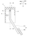
- FIG. 1 is a schematic configuration diagram of a brake-by-wire system including a side view of a brake pedal device including an inductive sensor according to a first embodiment.
- FIG. 2 is a plan view of the brake pedal device in the direction of arrow II in FIG. 1.
- FIG. 3 is a sectional view taken along line III-III in FIG. 2.
- FIG. 4 is a cross-sectional view taken along the line IV-IV in FIGS. 1 and 3.
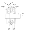
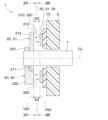
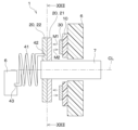
- FIG. FIG. 5 is an enlarged view of portion V in FIG. 4, and is a sectional view parallel to the axis of the shaft in the inductive sensor according to the first embodiment. 6 is a cross-sectional view taken along line VI-VI in FIG. 5.
- FIG. 5 is an enlarged view
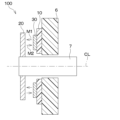
- FIG. 7 is a cross-sectional view parallel to the axis of the shaft in the inductive sensor of the first comparative example.
- FIG. 7 is a diagram showing a state in which a target has fallen off in an inductive sensor of a first comparative example.
- FIG. 5 is a sectional view showing a portion corresponding to FIG. 4 in a brake pedal device including an inductive sensor according to a second embodiment.
- FIG. 11 is an enlarged view of portion XI in FIG. 10, and is a cross-sectional view parallel to the axis of the shaft in the inductive sensor according to the second embodiment.
- FIG. 5 is a sectional view showing a portion corresponding to FIG. 4 in a brake pedal device including an inductive sensor according to a third embodiment.
- FIG. 7 is a cross-sectional view parallel to the axis of a shaft in an inductive sensor according to a fourth embodiment.
- 14 is a sectional view taken along line XIV-XIV in FIG. 13.
- FIG. 14 is a sectional view taken along line XV-XV in FIG. 13.
- FIG. FIG. 7 is a cross-sectional view parallel to the axis of a shaft in an inductive sensor according to a fifth embodiment.
- 17 is a cross-sectional view taken along line XVII-XVII in FIG. 16.
- FIG. 17 is a sectional view taken along line XVIII-XVIII in FIG.
- FIG. FIG. 7 is a cross-sectional view parallel to the axis of a shaft in an inductive sensor according to a sixth embodiment.
- 20 is a cross-sectional view taken along line XX-XX in FIG. 19.
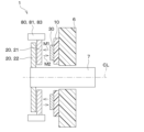
- FIG. 7 is a cross-sectional view parallel to the axis of a shaft in an inductive sensor according to a seventh embodiment.
- 17 is a sectional view taken along line XXII-XXII in FIG. 16.
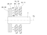
- FIG. It is a sectional view parallel to the axis of a shaft in an inductive sensor concerning an 8th embodiment. It is a sectional view parallel to the axis of a shaft in a sectional view of an inductive sensor according to a ninth embodiment.
- FIG. 7 is a cross-sectional view parallel to the axis of a shaft in an inductive sensor according to an eleventh embodiment.
- FIG. 5 is a sectional view showing a portion corresponding to FIG. 4 in a brake pedal device including an inductive sensor according to a twelfth embodiment.
- FIG. 30 is an enlarged view of the XXX portion of FIG. 29.
- FIG. 31 is a cross-sectional view taken along the XXXI-XXXI line in FIG. 30.
- FIG. 32 is a sectional view showing a portion corresponding to FIG. 31 in a brake pedal device including an inductive sensor according to a thirteenth embodiment.
- FIG. 32 is a sectional view showing a portion corresponding to FIG. 31 in a brake pedal device including an inductive sensor according to a fourteenth embodiment.
- 31 is a sectional view showing a portion corresponding to FIG. 30 in a brake pedal device including an inductive sensor according to a fifteenth embodiment.
- FIG. 32 is a sectional view showing a portion corresponding to FIG.
- FIG. 32 is a sectional view showing a portion corresponding to FIG. 31 in a brake pedal device including an inductive sensor according to a sixteenth embodiment, and is a diagram showing the state of the inductive sensor when the brake pedal is at the initial position.
- FIG. 32 is a sectional view showing a portion corresponding to FIG. 31 in a brake pedal device including an inductive sensor according to a sixteenth embodiment, and is a diagram showing the state of the inductive sensor when the brake pedal is at the maximum depression position.
- FIG. 32 is a sectional view showing a portion corresponding to FIG. 31 in a brake pedal device including an inductive sensor according to a second comparative example, and is a diagram showing the state of the inductive sensor when the brake pedal is at the initial position.
- FIG. 32 is a sectional view showing a portion corresponding to FIG.
- FIG. 31 in a brake pedal device including an inductive sensor according to a second comparative example, and is a diagram showing a state in which the shaft is eccentric when the brake pedal is at the initial position.
- FIG. 32 is a sectional view showing a portion corresponding to FIG. 31 in a brake pedal device including an inductive sensor according to a seventeenth embodiment, and is a diagram showing the state of the inductive sensor when the brake pedal is at the initial position.
- FIG. 31 is a sectional view showing a portion corresponding to FIG. 30 in a brake pedal device including an inductive sensor according to a seventeenth embodiment.
- FIG. 32 is a cross-sectional view showing a portion corresponding to FIG.
- FIG. 31 in a brake pedal device including an inductive sensor according to a third comparative example, and is a diagram showing the state of the inductive sensor when the brake pedal is at the initial position.
- FIG. 32 is a sectional view showing a portion corresponding to FIG. 31 in a brake pedal device equipped with an inductive sensor according to a third comparative example, and is a diagram showing a state in which the shaft is eccentric when the brake pedal is at the initial position.
- FIG. 32 is a sectional view showing a portion corresponding to FIG. 31 in a brake pedal device equipped with an inductive sensor according to a third comparative example, and is a diagram showing a state in which the shaft is eccentric when the brake pedal is at the initial position.
- an inductive sensor 1 according to a first embodiment is applied to a brake pedal device 2 mounted on a vehicle.
- This brake pedal device 2 is used in a brake-by-wire system 5 in which a brake mechanism 4 brakes a vehicle under drive control of an electronic control unit (hereinafter referred to as "ECU 3") mounted on the vehicle.
- ECU is an abbreviation for Electronic Control Unit.
- the brake pedal device 2 to which the inductive sensor 1 of the first embodiment is applied is used in a complete brake-by-wire system 5.
- a complete brake-by-wire system 5 means that the components of the brake mechanism 4 and the brake pedal are not mechanically connected, and the ECU 3 drives and controls the brake mechanism 4 based on the output signal of the inductive sensor 1 to operate the vehicle. This is a system that performs braking.
- a component of the brake mechanism 4 is, for example, a master cylinder.
- the brake pedal device 2 includes a housing 6, a shaft 7, a brake pedal 8, a reaction force generating mechanism 9, an inductive sensor 1, and the like.
- the housing 6 is directly fixed to the vehicle body with bolts (not shown) or indirectly fixed to the vehicle body via a base member (not shown). Specifically, the housing 6 is fixed to a dash panel or floor inside the vehicle.
- the housing 6 corresponds to an example of a fixed body. Bearings 61 and 62 for rotatably supporting the shaft 7 are provided inside the housing 6.
- the shaft 7 is formed into a rod shape and is supported by bearings 61 and 62 provided within the housing 6.
- the shaft 7 is rotatable within a predetermined angular range relative to the housing 6 in the circumferential direction of a circle centered on its own axis CL (hereinafter referred to as "around the axis").
- the shaft 7 corresponds to an example of a rotating body that is rotatably provided around a predetermined axis with respect to the housing 6 as a fixed body.
- the brake pedal 8 has a pedal arm 81 and a pedal pad 82.
- the pedal arm 81 has one end fixed to the shaft 7 and a pedal pad 82 provided at the other end.
- the pedal pad 82 is a part that is stepped on by the driver's foot.
- the brake pedal 8 swings in the forward and reverse directions around the axis of the shaft 7 within a predetermined angular range when depressed by the driver.
- the brake pedal 8 corresponds to an example of a movable body that operates in accordance with the movement of the shaft 7 as a rotating body.
- the reaction force generating mechanism 9 is composed of, for example, a spring, an actuator, etc.
- the reaction force generating mechanism 9 is a mechanism that generates a reaction force against the driver's depression force applied to the brake pedal 8.
- the brake pedal device 2 is equipped with the reaction force generating mechanism 9, so that even if the mechanical connection between the brake pedal 8 and the conventional master cylinder is abolished, when the brake pedal device 2 is connected to the master cylinder (that is, the reaction force generated by hydraulic pressure) It is possible to obtain a reaction force similar to the case in which a force is obtained).
- the inductive sensor 1 detects the position (specifically, the rotation angle) of a shaft 7 as a rotating body or a brake pedal 8 as a movable body with respect to a housing 6 as a fixed body. .
- the electrical signal output from the inductive sensor 1 is transmitted to the ECU 3.
- the ECU 3 is composed of a processor that performs control processing and arithmetic processing, a microcomputer including a storage section such as ROM and RAM that stores programs, data, etc., and its peripheral circuits.
- the storage unit is composed of a non-transitional tangible storage medium.
- the ECU 3 performs various control processes and calculation processes based on programs stored in the storage section, and controls the operation of each device connected to the output port. Specifically, the ECU 3 detects an accurate pedal operation amount (that is, the operation amount of the brake pedal 8) based on an electric signal transmitted from the inductive sensor 1 or the like, and controls the drive of the brake mechanism 4.
- the number of ECUs 3 is not limited to one, and the driving of the brake mechanism 4 may be controlled by a plurality of ECUs 3.
- the brake mechanism 4 may be an electric brake that brakes each wheel by driving an electric motor in response to a command from the ECU 3 and pressing a brake pad against a disc brake rotor.
- the brake mechanism 4 may be configured to increase the hydraulic pressure of brake fluid by operating a master cylinder or a hydraulic pump, drive a wheel cylinder disposed on each wheel, and operate the brake pad. good.
- the brake mechanism 4 is also capable of performing normal control, ABS control, VSC control, etc. in response to control signals from the ECU 3.
- ABS stands for Anti-lock Braking System
- VSC Vehicle Stability Control.
- the inductive sensor 1 is a sensor that utilizes the principle of mutual induction. Specifically, the inductive sensor 1 has a mechanism in which when a target having a conductive material approaches the transmitting coil, the magnetic field of the transmitting coil is canceled and the amount of magnetic flux passing through the receiving coil changes, and this change is read as an output. . The output corresponds to a detected value corresponding to the angular position around the axis of the detection target. Note that the transmitting coil is also called an excitation coil.
- the inductive sensor 1 of this embodiment includes a circuit board 10 and a plurality of targets 20.
- the circuit board 10 is fixed to a housing 6 as a fixed body.
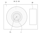
- a transmitting coil (not shown), a receiving coil (not shown), a receiving/transmitting circuit (not shown), and the like are mounted.
- the transmitting coil and the receiving coil are collectively referred to as the "transmitting/receiving coil 30."
- FIG. 2 shows a region on the circuit board 10 where the transmitter/receiver coil 30 is mounted.
- the transmitter/receiver circuit is constituted by an integrated circuit (IC) such as an ASIC, for example.
- the receiving and transmitting circuit supplies a high frequency to the transmitting coil and outputs a signal according to a change in the inductance of the receiving coil.
- the plurality of targets 20 include a first target 21 and a second target 22.
- the first target 21 among the plurality of targets 20, the one placed on the circuit board 10 side is called the first target 21, and the one placed on the opposite side of the circuit board 10 with the first target 21 in between is called the first target 21.
- the target will be referred to as the second target 22.
- the inductive sensor 1 is not limited to two targets 20 (that is, the first target 21 and the second target 22), and may have three or more targets 20. This also applies to each embodiment described below.
- the plurality of targets 20 are all configured to include a conductor. All of the plurality of targets 20 may be made of a conductor, or some of them may include a conductor.
- the plurality of targets 20 are fixed to the shaft 7 as a detection target. Therefore, the plurality of targets 20 move in synchronization with the shaft 7.
- the target 20 and the shaft 7 may be fixed by one or more of, for example, press-fitting, snap-fitting, caulking, and welding/welding.
- the plurality of targets 20 may be fixed independently with respect to the detection object, or as explained in the eleventh embodiment below, the plurality of targets 20 may be fixed to the detection object at the same time. It may be fixed with a fixing member. This also applies to each embodiment described below.
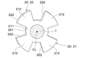
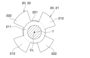
- the first target 21 has a cylindrical portion 211 surrounding the radially outer outer wall of the shaft 7, and a plurality of blade portions 212 extending radially outward from the cylindrical portion 211.
- the first target 21 has four blade parts 212.
- the second target 22 also has a cylindrical portion 221 surrounding the radially outer outer wall of the shaft 7, and a plurality of blade portions 222 extending radially outward from the cylindrical portion 221.
- the second target 22 also has four blades 222.
- the four blade portions 212 and 222 that each of the first target 21 and the second target 22 have are provided at predetermined intervals over the entire circumferential region of the cylinder portions 211 and 221 in the circumferential direction. It is possible to increase the output of the inductive sensor 1 by providing the four blade parts 212 and 222 in the entire circumferential area of the cylinder parts 211 and 221 in the circumferential direction.
- the first target 21 and the second target 22 are arranged so as to overlap in the thickness direction.
- the distance D1 between the first target 21 and the transmitting/receiving coil 30 (that is, the detection gap) is set to a distance at which mutual induction occurs.
- the distance D2 between the second target 22 and the transmitting/receiving coil 30 (that is, the detection gap) is also set to a distance at which mutual induction occurs.
- arrows M1 and M2 schematically indicate that mutual induction occurs in the detection gap between the target 20 and the transmitting/receiving coil 30.
- the shapes of the first target 21 and the second target 22 may or may not overlap. Good too.
- the shape of the first target 21 and the shape of the second target 22 are arranged with a slight deviation around the axial center (that is, a state in which they do not partially overlap). It shows.
- vibrations from the vehicle may be transmitted to the brake pedal device 2 mounted on the vehicle while the vehicle is running.
- the brake pedal device 2 may be used in high temperature or low temperature, and high humidity environments. Therefore, the target 20 attached to the brake pedal device 2 may fall off due to some reason (for example, vehicle vibration, loss of fixing force due to rust, etc.).
- FIG. 7 shows a state in which the first target 21 has fallen off the shaft 7 for some reason in the inductive sensor 1 of the first embodiment.
- the inductive sensor 1 of the first embodiment can detect the positions of the shaft 7 and brake pedal 8 using the second target 22 even if the first target 21 falls off. It is possible.
- the inductive sensor 100 of the first comparative example includes one target 20 and a circuit board 10 on which a transmitting/receiving coil 30 and the like are mounted.
- FIG. 9 shows a state in which the target 20 has fallen off the shaft 7 for some reason in the inductive sensor 100 of the first comparative example.
- the inductive sensor 100 of the first comparative example has an abnormal output when the target 20 falls off.
- the inductive sensor 100 of the first comparative example has a configuration capable of outputting a plurality of detected values from the circuit board 10, if the target 20 falls off, all of them will be considered to be abnormal outputs. Become.
- the inductive sensor 1 and brake pedal device 2 of the first embodiment have the following configuration and the effects thereof.
- the inductive sensor 1 of the first embodiment includes a plurality of targets 20 fixed to a detection target so as to move in synchronization with the motion of the detection target (for example, the shaft 7 or the brake pedal 8). According to this, even if one target 20 among the plurality of targets 20 falls off or is deformed, the position of the detection target can be correctly detected using another target 20 and the transmitting/receiving coil 30. Therefore, the inductive sensor 1 can ensure redundancy in detecting the position of the detection target even if the target 20 falls off or deforms.
- the brake pedal device 2 of the first embodiment detects the position (specifically, the rotation angle) of the shaft 7 and the brake pedal 8 as detection targets using the inductive sensor 1 equipped with a plurality of targets 20. .
- the inductive sensor 1 that detects the positions of the shaft 7 and the brake pedal 8 of the brake pedal device 2 malfunctions, braking of the vehicle may be hindered.
- the brake pedal device 2 of the first embodiment since the inductive sensor 1 includes a plurality of targets 20, there is redundancy in detecting the positions of the shaft 7 and the brake pedal 8 against falling off or deformation of the targets 20. It is possible to ensure the Therefore, this brake pedal device 2 can improve the safety of vehicle braking by the brake-by-wire system 5.
- the inductive sensor 1 has a plurality of transmitting and receiving coils 30 mounted on one circuit board 10, and is capable of outputting a plurality of detection values. It is the composition.
- the first transmitting/receiving coil 31 among the plurality of transmitting/receiving coils 30 is mounted on one surface of the circuit board 10 .
- the second transmitting/receiving coil 32 among the plurality of transmitting/receiving coils 30 is mounted on the other surface of the circuit board 10 .
- One circuit board 10 and a plurality of transmitting/receiving coils 30 (specifically, a first transmitting/receiving coil 31 and a second transmitting/receiving coil 32) mounted thereon are housed in a sensor housing 40, and a housing as a fixed body. It is fixed at 6.
- the plurality of targets 20 include a first target 21 and a second target 22.
- the first target 21 is arranged on one side of the circuit board 10 in the thickness direction
- the second target 22 is arranged on the other side of the circuit board 10 in the thickness direction.
- the first target 21 and the second target 22 are fixed to the shaft 7 as a detection target. Therefore, the first target 21 and the second target 22 move in synchronization with the shaft 7.
- the first target 21 and the second target 22 are composed of cylindrical portions 211 and 221 surrounding the radially outer wall of the shaft 7, and the same as that shown in FIG. 6 in the first embodiment. It has a plurality of blade parts 212 and 222 extending radially outward from the cylinder parts 211 and 221.
- the plurality of blade parts 212 and 222 that the first target 21 and the second target 22 each have are provided at predetermined intervals over the entire circumference in the circumferential direction of the cylinder parts 211 and 221. It is possible to increase the output of the inductive sensor 1 by providing the plurality of blade parts 212, 222 over the entire circumference in the circumferential direction of the cylinder parts 211, 221.
- the distance D3 between the first target 21 and the first transmitting/receiving coil 31 is set to a distance at which mutual induction occurs. Therefore, the first transmitting/receiving coil 31 can output a signal according to the position of the first target 21.
- the distance D4 between the second target 22 and the second transmitting/receiving coil 32 is also set to a distance at which mutual induction occurs. Therefore, the second transmitting/receiving coil 32 can output a signal according to the position of the second target 22.
- the distance D3 between the first target 21 and the first transmitting/receiving coil 31 and the distance D4 between the second target 22 and the second transmitting/receiving coil 32 are the same.
- “the distance D3 and the distance D4 are the same” includes not only a state in which those distances completely match, but also a state in which the distances are slightly deviated due to manufacturing tolerances.
- the inductive sensor 1 and brake pedal device 2 of the second embodiment described above have the following configuration and the effects thereof.
- the plurality of targets 20 include at least a first target 21 and a second target 22.
- the transmitting/receiving coil 30 includes at least a first transmitting/receiving coil 31 that outputs a detected value according to the position of the first target 21 and a second transmitting/receiving coil 32 that outputs a detected value according to the position of the second target 22.
- the inductive sensor 1 includes a first sensor section configured by the first target 21 and the first transmitting/receiving coil 31, and a second sensor section configured by the second target 22 and the second transmitting/receiving coil 32. Be prepared.
- the inductive sensor 1 can ensure redundancy in detecting the position of the detection target even if the target 20 falls off or deforms.
- the distance D3 between the first target 21 and the first transmitting/receiving coil 31 is the same as the distance D4 between the second target 22 and the second transmitting/receiving coil 32. According to this, it is possible to make the detection value of the first sensor section and the detection value of the second sensor section substantially the same regarding position detection of the detection target. Therefore, in the ECU 3 to which the detection value of the inductive sensor 1 is transmitted, post-processing of the detection value of the first sensor section and the detection value of the second sensor section is eliminated or simplified, and the two detection values are It becomes possible to easily compare the
- the signal amplitude of the sensor output is small. It will never happen. If the signal amplitude is large, the signal-to-noise ratio (that is, signal-to-noise ratio) becomes large, and the influence of noise on transmission becomes small, so that the position of the detection target can be detected with high precision.
- the first transmitting/receiving coil 31 is mounted on one surface of one circuit board 10, and the second transmitting/receiving coil 32 is mounted on the other surface. Further, the first target 21 is arranged on one side of the circuit board 10 in the thickness direction, and the second target 22 is arranged on the other side of the circuit board 10 in the thickness direction. With such a configuration, it is possible to make the distance D3 between the first target 21 and the first transmitting/receiving coil 31 and the distance D4 between the second target 22 and the second transmitting/receiving coil 32 the same.
- the third embodiment differs from the second embodiment in the fixing method of the target included in the inductive sensor 1, and is otherwise the same as the second embodiment, so there are no differences from the second embodiment. I will only explain about.
- the inductive sensor 1 of the third embodiment also includes a circuit board 10 and a plurality of targets 20.
- the second target 22 among the plurality of targets 20 is fixed to the shaft 7.
- the first target 21 among the plurality of targets 20 is fixed to a pedal arm 81 as an example of a component that operates in synchronization with the shaft 7 .
- the first target 21 is fixed to a plurality of arm portions 83 extending from the pedal arm 81 in the axial direction.
- the parts to which the plurality of targets 20 are each fixed do not have to be the same, but only need to be in synchronization with the rotation of the detection target.
- the inductive sensor 1 includes a circuit board 10 and a plurality of targets 20.
- the plurality of targets 20 include a first target 21 and a second target 22.
- the first target 21 and the second target 22 each include cylindrical portions 211 and 221 surrounding the radially outer outer wall of the shaft 7, and a plurality of cylindrical portions 211 and 221 that extend radially outward from the cylindrical portions 211 and 221. It has blade parts 212 and 222.
- the cylindrical portion 211 of the first target 21 and the cylindrical portion 221 of the second target 22 are fixed to the shaft 7.
- the plurality of blade parts 212 of the first target 21 and the plurality of blade parts 222 of the second target 22 are located at positions shifted in the circumferential direction (in other words, they do not overlap in the axial direction). location).
- a surface 210 facing the first transmitting/receiving coil 31 among the plurality of blade parts 212 of the first target 21 is arranged on the first virtual plane VS1.
- a surface 220 of the plurality of blade portions 222 of the second target 22 facing the second transmitting/receiving coil 32 is also arranged on the first virtual plane VS1.
- the inductive sensor 1 of the fourth embodiment has a plurality of transmitting/receiving coils 30 mounted on one circuit board 10, and has a configuration capable of outputting a plurality of detected values. .
- the first transmitting/receiving coil 31 and the second transmitting/receiving coil 32 are mounted in an electrically independent state.
- the first transmitting/receiving coil 31 and the second transmitting/receiving coil 32 are mounted on one surface of the circuit board 10 in an overlapping state.
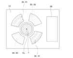
- the region where the first transmitting/receiving coil 31 and the second transmitting/receiving coil 32 are mounted on the circuit board 10 is shown with dashed hatching, although it is not a cross section.
- various shapes for example, a sine wave shape
- a circuit board 10 on which a plurality of transmitting/receiving coils 30 and a receiving/transmitting circuit 35 are mounted is fixed to a housing 6 as a fixed body.
- the first transmitting/receiving coil 31 and the second transmitting/receiving coil 32 are arranged on the circuit board 10 on a second virtual plane VS2 parallel to the first virtual plane VS1.
- "the first transmitting/receiving coil 31 and the second transmitting/receiving coil 32 are arranged on the second virtual plane” means that the first transmitting/receiving coil 31, the second transmitting/receiving coil 32, and the second transmitting/receiving coil 32 are arranged on the second virtual plane.
- the state in which the virtual plane corresponds exactly with the virtual plane it also includes the state in which there is a slight deviation.
- the slightly deviated state includes, for example, a state in which the first transmitting/receiving coil 31, the second transmitting/receiving coil 32, and the second virtual plane are slightly deviated by the thickness of the coil wire and the layer thickness of the circuit board 10. is exemplified.
- the inductive sensor 1 and brake pedal device 2 of the fourth embodiment described above have the following configuration and the effects thereof.
- a surface 210 of the first target 21 facing the first transmitting/receiving coil 31 and a surface 220 of the second target 22 facing the second transmitting/receiving coil 32 are arranged on the first virtual plane VS1. be done. Further, a surface 310 of the first transmitting/receiving coil 31 facing the first target 21 and a surface 320 of the second transmitting/receiving coil 32 facing the second target 22 are defined by a second virtual plane parallel to the first virtual plane VS1. It is placed on the plane VS2.
- the distance D3 between the first target 21 and the first transmitting/receiving coil 31 is the same as the distance D4 between the second target 22 and the second transmitting/receiving coil 32. It is. Therefore, even if either the first target 21 or the second target 22 falls off the shaft 7 for some reason and the position of the detection target is detected by the other target 20, the signal amplitude of the sensor output is small. It will never happen. If the signal amplitude is large, the signal-to-noise ratio (that is, signal-to-noise ratio) becomes large, and the influence of noise on transmission becomes small, so that the position of the detection target can be detected with high precision.
- the signal-to-noise ratio that is, signal-to-noise ratio
- the inductive The size of the sensor 1 can be reduced in size.
- the fifth embodiment also differs from the first embodiment etc. in the configuration of the inductive sensor 1, and is otherwise the same as the first embodiment etc., so only the different parts from the first embodiment etc. explain.
- the inductive sensor 1 includes a circuit board 10 and a plurality of targets 20.
- the plurality of targets 20 are the same as those described in the fourth embodiment. That is, as shown in FIG. 16, the surface 210 facing the first transmitting/receiving coil 31 among the plurality of blade parts 212 of the first target 21 is arranged on the first virtual plane VS1. A surface 220 of the plurality of blade portions 222 of the second target 22 facing the second transmitting/receiving coil 32 is also arranged on the first virtual plane VS1.
- the inductive sensor 1 of the fifth embodiment also has a plurality of transmitting/receiving coils 30 mounted on one circuit board 10, and has a configuration capable of outputting a plurality of detected values.
- the first transmitting/receiving coil 31 and the second transmitting/receiving coil 32 are mounted in an electrically independent state.
- a region where the first transmitter/receiver coil 31 is mounted on the circuit board 10 is shown with dashed-dotted line hatching rather than a cross section.
- a region where the second transmitting/receiving coil 32 is mounted on the circuit board 10 is shown with broken line hatching, although it is not a cross section.
- the first transmitting/receiving coil 31 and the second transmitting/receiving coil 32 are mounted in different areas on one surface of the circuit board 10, respectively. By mounting the first transmitting/receiving coil 31 and the second transmitting/receiving coil 32 in different areas, it is possible to suppress the first transmitting/receiving coil 31 and the second transmitting/receiving coil 32 from being mutually influenced by the magnetic field. . Therefore, even if either the first transmitting/receiving coil 31 or the second transmitting/receiving coil 32 fails for some reason and the position of the detection target is detected by the other transmitting/receiving coil 30, the output signal of the sensor effects are prevented from occurring.
- a circuit board 10 on which a plurality of transmitting/receiving coils 30 and a receiving/transmitting circuit 35 are mounted is fixed to a housing 6 as a fixed body.
- the first transmitting/receiving coil 31 and the second transmitting/receiving coil 32 are arranged on the circuit board 10 on a second virtual plane VS2 parallel to the first virtual plane VS1. Therefore, the distance D3 between the first target 21 and the first transmitting/receiving coil 31 is the same as the distance D4 between the second target 22 and the second transmitting/receiving coil 32.
- the inductive sensor 1 and brake pedal device 2 of the fifth embodiment described above have the following configuration and the effects thereof.
- the first transmitting/receiving coil 31 and the second transmitting/receiving coil 32 are mounted in different areas on one surface of the circuit board 10. Therefore, it is possible to suppress the first transmitting/receiving coil 31 and the second transmitting/receiving coil 32 from being mutually influenced by the magnetic field. Therefore, even if either the first transmitting/receiving coil 31 or the second transmitting/receiving coil 32 fails for some reason and the position of the detection target is detected by the other transmitting/receiving coil 30, the sensor output signal will not be affected. It is possible to prevent the effects from occurring.
- the inductive sensor 1 since the detection gap between the plurality of targets 20 and the transmitting/receiving coil 30 is at one location, compared to the second and third embodiments, the inductive sensor 1 is The body size can be reduced.
- the inductive sensor 1 includes a circuit board 10 and a plurality of targets 20. At least one target 20 among the plurality of targets 20 has at least a portion of the portion facing the transmitting/receiving coil 30 formed of a conductor 25, and the remaining portion formed of an insulator 26.
- the cylindrical portion 211 and the portion of the blade portion 212 on the opposite side from the transmitting/receiving coil 30 are formed of the insulator 26.
- resin is used as the insulator 26.
- a portion of the blade portion 212 on the transmitting/receiving coil 30 side is formed of the conductor 25 .
- the conductor 25 a metal such as aluminum is used, for example.
- the second target 22 may also have at least a portion of the portion facing the transmitting/receiving coil 30 formed of the conductor 25, and the remaining portion formed of the insulator 26.
- the inductive sensor 1 and brake pedal device 2 of the sixth embodiment described above have the following configuration and the effects thereof.
- At least one target 20 among the plurality of targets 20 has at least a portion of the portion facing the transmitting/receiving coil 30 formed of the conductor 25, and the remaining portion formed of the insulator 26. has been done. According to this, the portion of the target 20 that requires the function of canceling the magnetic field can be formed from the conductor 25, and the remaining portion can be formed by selecting a low-cost insulating material.
- the insulator 26 forming a part of the target 20 is made of resin, and the resin is used in the part where the target 20 is fixed to the detection target (specifically, the shaft 7). .
- the part of the target 20 that is fixed to the detection target is made of resin, so that the target 20 can be prevented from falling off due to rust or the like. Furthermore, even if the part of the target 20 that is fixed to the detection target has a complicated shape, it can be easily made of resin by injection molding.
- the portion facing the transmitting/receiving coil 30 is formed of the conductor 25, and the remaining portion is formed of the insulator 26.
- the plurality of targets 20 it is possible to further achieve fixed redundancy. That is, when two or more targets 20 are provided, the entire target 20 is made of a conductor 25 (e.g., aluminum), and the part of the target 20 that is fixed to the detection target is made of an insulator (e.g., resin). ) There are two or more types depending on what is formed.
- both targets 20 are made of aluminum, there is a risk that they will corrode due to the same factors. Furthermore, if the two targets 20 are both made of resin, there is a risk that the part of the targets 20 that is fixed to the detection target will creep at high temperatures, weakening the force of fixing it to the shaft 7, and causing both of them to fall off. There is.
- the entire target 20 may be made of a conductor 25 (e.g., aluminum), and the portion of the target 20 that is fixed to the detection target may be made of an insulator (e.g., There are two or more types depending on what is made of (resin). This prevents all the targets 20 from falling due to the same cause, thereby further providing fixed redundancy.
- the seventh embodiment also differs from the first embodiment etc. in the configuration of the inductive sensor 1, and is otherwise the same as the first embodiment etc., so only the different parts from the first embodiment etc. explain.
- the inductive sensor 1 includes a circuit board 10, a plurality of targets 20, and a torsion spring 41.
- the torsion spring 41 applies a load to at least one target 20 among the plurality of targets 20 in the circumferential direction around the axis CL of the shaft 7. .
- the torsion spring 41 applies a load to the second target 22.
- One end 42 of the torsion spring 41 is locked to a part of the second target 22, and the other end 43 of the torsion spring 41 is locked to a part of the housing 6 as a fixed body.
- the torsion spring 41 applies a load only to the second target 22, but the present invention is not limited to this.
- the torsion spring 41 may apply a load only to the first target 21 or may apply a load to both the first target 21 and the second target 22.
- the inductive sensor 1 and brake pedal device 2 of the seventh embodiment described above have the following configuration and the effects thereof.
- the torsion spring 41 is configured to apply a load to at least one target 20 among the plurality of targets 20 in the circumferential direction around the axis CL. According to this, even if the target 20 has a small deviation width in the circumferential direction around the axis CL, the biasing force of the torsion spring 41 causes the target 20 to move to one side in the circumferential direction. Since the target 20 is pressed against it, the target 20 is prevented from shaking.
- the inductive sensor 1 of the eighth embodiment also includes a circuit board 10 and a plurality of targets 20.
- the first target 21 among the plurality of targets 20 is fixed to a member 80 that operates in synchronization with a rotating body (for example, the shaft 7) as a detection target.
- the member 80 is, for example, the pedal arm 81 or a component connected thereto (for example, the arm portion 83 described in the third embodiment).
- the second target 22 among the plurality of targets 20 is fixed to a rotating body (for example, the shaft 7).
- the parts to which the plurality of targets 20 are each fixed do not have to be the same, and may be members that operate in synchronization with the rotation of the detection target.
- the ninth embodiment is a modification of the first embodiment.
- the inductive sensor 1 of the ninth embodiment includes a plurality of circuit boards 10 and a plurality of targets 20.
- the plurality of targets 20 are fixed to the shaft 7 as a detection target. Therefore, the plurality of targets 20 move in synchronization with the shaft 7.
- the one placed on the circuit board 10 side among the plurality of targets 20 is called the first target 21, and the one placed on the opposite side from the plurality of circuit boards 10 with the first target 21 in between is called the first target 21. It is called a second target 22.
- the plurality of circuit boards 10 include a first circuit board 11 and a second circuit board 12. It is assumed that the first circuit board 11 and the second circuit board 12 are arranged side by side in the axial direction of the shaft 7, and both are fixed to the housing 6 as a fixed body.
- the first circuit board 11 and the second circuit board 12 are arranged side by side in the axial direction of the shaft 7, and both are fixed to the housing 6 as a fixed body.
- the second circuit board 12 the one placed on the side of the plurality of targets 20 among the plurality of circuit boards 10
- the first circuit board 11 A first transmitting/receiving coil 31 is mounted on the first circuit board 11 .
- a second transmitting/receiving coil 32 is mounted on the second circuit board 12 .
- the first transmitting/receiving coil 31 detects the angle of the first target 21.
- the second transmitting/receiving coil 32 also detects the angle of the first target 21.
- the detection gap between the first transmitting/receiving coil 31 and the second target 22 becomes large, so the first transmitting/receiving coil 31 cannot be detected or is detected incorrectly. There is a risk of However, the second transmitting/receiving coil 32 can detect the angle of the second target 22.
- the inductive sensor 1 and brake pedal device 2 of the ninth embodiment described above can also ensure redundancy in detecting the position of the detection target in case the target 20 falls off.
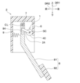
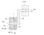
- the rotation axis CL of the shaft 7 included in the brake pedal device 2 is different from the rotation axis SC of the plurality of targets 20 included in the inductive sensor 1.
- the axis SC of rotation of the target 20 will be referred to as "sensor axis SC.”
- the inductive sensor 1 includes a plurality of targets 20 and a circuit board 10 on which a transmitting/receiving coil 30, a receiving/transmitting circuit, etc. are mounted in a sensor housing 40.
- the sensor case 40 and the housing 6 may be formed integrally.
- the plurality of targets 20, the transmitting/receiving coil 30, the circuit board 10, etc. included in the inductive sensor 1 may adopt the configurations described in the first to ninth embodiments.
- a plurality of targets 20 are fixed to a sensor rotation shaft 23.
- the sensor rotation shaft 23 is rotatable around the sensor axis SC.
- a sensor arm 24 is fixed to the sensor rotation shaft 23.
- the sensor arm 24 extends in a direction perpendicular to the sensor axis SC.
- a connecting portion 27 is provided at the end of the sensor arm 24 on the opposite side to the sensor rotating shaft 23 .
- the connecting portion 27 is inserted into a long hole 84 provided in a part of the pedal arm 81. Note that the sensor rotating shaft 23, the sensor arm 24, and the connecting portion 27 may be formed integrally.
- the brake pedal 8 and the shaft 7 rotate around the axis CL.
- the operation of the pedal arm 81 is transmitted from the elongated hole 84 to the connecting portion 27, the sensor arm 24, and the sensor rotating shaft 23, and the plurality of targets 20 rotate around the sensor axis SC.
- the inductive sensor 1 outputs a signal corresponding to the position of a target 20 that operates in synchronization with the brake pedal 8.
- the rotation axis CL of the shaft 7 included in the brake pedal device 2 and the sensor axis SC of the inductive sensor 1 may be located at different positions.
- the tenth embodiment can also provide the same effects as the first to ninth embodiments described above.
- the configuration in which the axis of rotation CL of the shaft 7 provided in the brake pedal device 2 and the sensor axis SC of the inductive sensor 1 are located at different positions is not limited to the one illustrated in the tenth embodiment, and may include a link mechanism, etc. Various configurations applying this can be adopted.
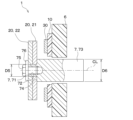
- the eleventh embodiment describes an example of a method for fixing a plurality of targets 20 in contrast to the first embodiment and the like.
- the plurality of targets 20 are fixed to the shaft 7 as the detection target with the same fixing member (for example, bolt 75).
- a screw hole 72 is provided in the axial end portion 71 of the shaft 7 so as to extend in the axial direction. Further, the outer diameter D5 of the end portion 71 of the shaft 7 is smaller than the outer diameter D6 of the base portion 73 of the shaft 7. Therefore, a step 74 is provided between the end 71 and the base 73 of the shaft 7. The first target 21 and the second target 22 are fitted onto the end 71 of the shaft 7, and the surface of the first target 21 opposite to the second target 22 is in contact with the step 74. .
- a bolt 75 which is an example of a fixing member, is screwed into the screw hole 72 of the shaft 7.
- the first target 21 and the second target 22 are fixed in a pressed state against the step 74 by a washer portion 76 provided on the head of the bolt 75.
- a mechanism for preventing relative rotation between the first target 21, the second target 22, and the shaft 7 may be provided as necessary.
- the plurality of targets 20 are fixed to the detection target so as to move in synchronization with the movement of the detection target (for example, the shaft 7 or the brake pedal 8).
- the inductive sensor 1 and brake pedal device 2 of the eleventh embodiment described above have a configuration in which a plurality of targets 20 are fixed to the detection target using the same fixing member so as to move in synchronization with the motion of the detection target. Even with this configuration, if one target 20 among the plurality of targets 20 is damaged, deformed, or falls off, the position of the detection target can be correctly detected using another target 20 and the transmitting/receiving coil 30. Therefore, the inductive sensor 1 of the eleventh embodiment can also ensure redundancy in detecting the position of the detection target against damage to the target 20, etc., as in the first embodiment and the like described above.
- the bolt 75 is exemplified as the fixing member that fixes the plurality of targets 20 and the shaft 7, but the present invention is not limited thereto.
- Various members and methods such as fixing pins, caulking, snap-fitting, press-fitting, welding, and welding can be used as fixing members or fixing methods for the plurality of targets 20 and the shaft 7, for example. It is also possible to use these members and methods in combination.
- the method of fixing the plurality of targets 20 and the detection object described in the eleventh embodiment is applicable to the first to seventeenth embodiments.
- the twelfth embodiment also describes an example of a method for fixing a plurality of targets 20 in contrast to the first embodiment and the like.
- the plurality of targets 20 include a first target 21 and a second target 22.
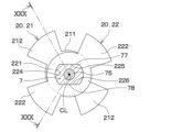
- the first target 21 and the second target 22 each have cylindrical portions 211 and 221, arm portions 213 and 223, and a plurality of blade portions 212 and 222.
- the cylindrical portions 211 and 221 are portions surrounding the radially outer outer wall of the shaft 7 .
- the arm portions 213 and 223 are portions that extend from the outer edges of the cylindrical portions 211 and 221 toward the circuit board 10 in the axial direction.
- the plurality of blade portions 212 and 222 are portions of the arm portions 213 and 223 that extend radially outward from the portion on the circuit board 10 side.
- both the first target 21 and the second target 22 are fixed to the shaft 7 as a rotating body with the same bolt 75.
- the end 71 of the shaft 7 in the axial direction is inserted into a first hole 214 of the first target 21 and a second hole 224 of the second target 22.
- a screw hole 72 is provided in the end portion 71 of the shaft 7 so as to extend in the axial direction.
- a bolt 75 is screwed into the screw hole 72 of the shaft 7.
- the first target 21 and the second target 22 are fixed in a pressed state against a step 74 provided on the shaft 7 by the axial force of the bolt 75.
- the anti-rotation structure includes two second target-side flat parts 225 and 226 formed on the inner wall of the second hole 224 of the second target 22, and two shafts provided on the outer wall of the shaft 7. It is composed of side plane parts 77 and 78. Thereby, the anti-rotation structure restricts the relative rotation between the second target 22 and the shaft 7.
- the anti-rotation structure includes two first target-side flat parts formed on the inner wall of the first hole 214 of the first target 21 and two shafts provided on the outer wall of the shaft 7. It is also constituted by side plane parts 77 and 78. Thereby, the anti-rotation structure restricts relative rotation between the first target 21 and the shaft 7. Therefore, even if the bolt 75 becomes loose, the rotation preventing structure can prevent the first target 21, the second target 22, and the shaft 7 from rotating relative to each other.
- the plurality of blade portions 212 of the first target 21 and the plurality of blade portions 222 of the second target 22 are arranged at circumferentially shifted positions, in other words, at positions that do not overlap in the axial direction.
- a surface 210 facing the first transmitting/receiving coil 31 among the plurality of blade portions 212 of the first target 21 is arranged on the first virtual plane VS1.
- a surface 220 of the plurality of blade portions 222 of the second target 22 facing the second transmitting/receiving coil 32 is also arranged on the first virtual plane VS1.
- the first transmitting/receiving coil 31 and the second transmitting/receiving coil 32 are arranged on the circuit board 10 on a second virtual plane VS2 parallel to the first virtual plane VS1.
- "the first transmitting/receiving coil 31 and the second transmitting/receiving coil 32 are arranged on the second virtual plane” means that the first transmitting/receiving coil 31, the second transmitting/receiving coil 32, and the second transmitting/receiving coil 32 are arranged on the second virtual plane.
- the state in which the virtual plane corresponds exactly with the virtual plane it also includes the state in which there is a slight deviation.
- the slightly deviated state includes, for example, a state in which the first transmitting/receiving coil 31, the second transmitting/receiving coil 32, and the second virtual plane are slightly deviated by the thickness of the coil wire and the layer thickness of the circuit board 10. is exemplified.
- the inductive sensor 1 and brake pedal device 2 of the twelfth embodiment described above have the following configuration and the effects thereof.
- both the first target 21 and the second target 22 are fixed to the shaft 7 as a rotating body by the same bolt 75. According to this, the first target 21 and the second target 22 can be easily fixed to the shaft 7 without requiring any special equipment.
- the inductive sensor 1 includes a rotation prevention structure that restricts the relative rotation between the first target 21 and the shaft 7, and restricts the relative rotation between the second target 22 and the shaft 7. According to this, even if the bolt 75 becomes loose, the first target 21, the second target 22, and the shaft 7 will not rotate relative to each other. Therefore, the inductive sensor 1 can continue to correctly detect the positions of the shaft 7 and the brake pedal 8 as detection targets, and can ensure redundancy in detecting the positions of the detection targets.
- the thirteenth embodiment describes another specific example of the rotation prevention structure compared to the twelfth embodiment.
- the relative rotation of both the first target 21 and the second target 22 with respect to the shaft 7 is regulated by the rotation prevention structure.
- the anti-rotation structure includes one second target-side flat part 225 formed on the inner wall of the second hole 224 of the second target 22 and one shaft-side flat part provided on the outer wall of the shaft 7. 77.
- the rotation prevention structure includes one first target side flat portion formed on the inner wall of the first hole 214 of the first target 21 and one shaft provided on the outer wall of the shaft 7. It is also constituted by a side plane portion 77.
- the anti-rotation structure restricts relative rotation between the first target 21 and the shaft 7. Therefore, in the thirteenth embodiment, as in the twelfth embodiment, even if the bolt 75 becomes loose, it is possible to prevent the first target 21, the second target 22, and the shaft 7 from rotating relative to each other.
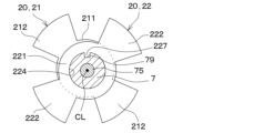
- the fourteenth embodiment also describes another specific example of the rotation prevention structure with respect to the twelfth embodiment.
- the anti-rotation structure includes a protrusion 227 that protrudes radially inward from the inner wall of the second hole 224 of the second target 22 and a recess 79 provided in the outer wall of the shaft 7 .
- the protrusion 227 of the second target 22 fits into the recess 79 of the shaft 7 .
- the anti-rotation structure restricts the relative rotation between the second target 22 and the shaft 7.
- the anti-rotation structure also includes a protrusion that protrudes radially inward from the inner wall of the first hole 214 of the first target 21 and a recess 79 provided in the outer wall of the shaft 7. ing.
- the protrusion of the first target 21 fits into the recess 79 of the shaft 7 .
- the anti-rotation structure restricts relative rotation between the first target 21 and the shaft 7. Therefore, in the 14th embodiment, as in the 12th and 13th embodiments, even if the bolt 75 becomes loose, it is possible to prevent the first target 21, the second target 22, and the shaft 7 from rotating relative to each other. .
- the fifteenth embodiment differs from the twelfth to fourteenth embodiments in that the method for fixing the plurality of targets 20 is changed.
- both the first target 21 and the second target 22 are fixed to the shaft 7 as a rotating body by caulking 701.
- the end 71 of the shaft 7 in the axial direction has a shape shown by a broken line 702 before being caulked.
- the portion indicated by the broken line 702 is inserted into the first hole 214 of the first target 21 and the second hole 224 of the second target 22.
- the portion indicated by the broken line 702 is pressurized from the axial direction and crushed, thereby performing caulking.
- the end 71 of the shaft 7 in the axial direction can fix the first target 21 and the second target 22 by caulking 701.
- the fifteenth embodiment may also include the anti-rotation structure described in the twelfth to fourteenth embodiments.
- the inductive sensor 1 and brake pedal device 2 of the fifteenth embodiment described above have the following configuration and the effects thereof.
- both the first target 21 and the second target 22 are fixed to the shaft 7 by caulking 701. According to this, the component cost of the bolt 75 can be reduced compared to a configuration in which the first target 21 and the second target 22 are fixed to the shaft 7 with the bolt 75.
- the detection surface of the target 20 is required to be placed on the first virtual plane VS1 shown in FIG. 20 (ie, the length of the arm portions 223, 223) can be reduced. Therefore, the size of the inductive sensor 1 in the axial direction can be reduced.
- the detection surface of the target 20 refers to the surface 210 facing the first transmitting/receiving coil 31 among the plurality of blades 212 of the first target 21 and the second surface of the plurality of blades 222 of the second target 22. This is a surface 220 facing the transmitting/receiving coil 32.
- (16th embodiment) A sixteenth embodiment will be described.
- the size of the transmitting/receiving coil 30 is changed from the 5th and 12th to 15th embodiments.
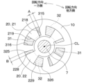
- FIG. 35 shows a state in which the centers of the bearings 61 and 62 of the housing 6 and the axis CL of the shaft 7 are in the same position, and the driver's pedal force is not applied to the brake pedal 8, that is, the brake pedal 8 is It shows the state of the inductive sensor 1 when it is in the initial position.
- the angle of the target 20 with respect to the circuit board 10 is, for example, 0°.
- FIG. 36 shows a state in which the centers of the bearings 61 and 62 of the housing 6 and the axis CL of the shaft 7 are in the same position, and the brake pedal 8 is in the most depressed position, that is, the brake pedal 8 is in the maximum depressed position.
- 1 shows the state of the inductive sensor 1 when the inductive sensor 1 is in the state shown in FIG. In this state, the angle of the target 20 with respect to the circuit board 10 is, for example, X°. Therefore, when the brake pedal 8 rotates from the initial position to the maximum depression position, the target 20 rotates in the range of 0° to X°.
- the direction in which the target 20 rotates with respect to the circuit board 10 together with the depression of the brake pedal 8 when the driver's depression force on the brake pedal 8 increases is referred to as "one side of the rotation direction.”
- the direction in which the target 20 rotates with respect to the circuit board 10 together with the return movement of the brake pedal 8 is referred to as the "other side of the rotation direction.”
- FIGS. 35 and 36 the area where the first transmitting/receiving coil 31 is mounted on the circuit board 10 is shown with dash-dotted line hatching instead of the cross section, and the area where the second transmitting/receiving coil 32 is mounted is shown with dashed line hatching. Although it is not a cross section, it is shown with dashed hatching. It should be noted that the dashed-dotted line and dashed line hatching are not applied to locations where the transmitting/receiving coil 30 and the target 20 overlap in the axial direction. This also applies to the seventeenth embodiment, second comparative example, and third comparative example, which will be described later.
- the range in which the first transmitting/receiving coil 31 is mounted on the circuit board 10 is larger than the rotation range of the first target 21 (i.e., 0° to X°). It is large on one side of the rotational direction of the first target 21 and on the other side of the rotational direction. Further, the range in which the second transmitting/receiving coil 32 is mounted on the circuit board 10 is also on one side in the rotation direction of the second target 22 and on the other side in the rotation direction of the second target 22 with respect to the rotation range of the second target 22 (i.e., 0° to X°). big.
- the distance A from the end 315 of is greater than the predetermined distance D1.
- the predetermined distance D1 is a distance by which the first target 21 may move relative to the circuit board 10 due to rattling between the bearings 61 and 62 of the housing 6 and the shaft 7.
- the distance B between the end 228 of the second target 22 on the other side in the rotational direction and the end 325 of the second transmitting/receiving coil 32 on the other side in the rotational direction is greater than the predetermined distance D2.
- the predetermined distance D2 is a distance by which the second target 22 may move relative to the circuit board 10 due to rattling between the bearings 61 and 62 of the housing 6 and the shaft 7.
- the predetermined distance D3 is a distance by which the first target 21 may move relative to the circuit board 10 due to rattling between the bearings 61 and 62 of the housing 6 and the shaft 7.
- the distance D between the end 229 of the second target 22 on one side in the rotational direction and the end 326 of the second transmitting/receiving coil 32 on the one side in the rotational direction is greater than the predetermined distance D4.
- the predetermined distance D4 is a distance by which the second target 22 may move relative to the circuit board 10 due to rattling between the bearings 61 and 62 of the housing 6 and the shaft 7.
- FIG. 37 shows the state of the inductive sensor when the centers of the bearings 61 and 62 of the housing 6 and the axis CL of the shaft 7 are at the same position and the brake pedal 8 is at the initial position.
- the first target 21 is at 0°
- the side end portion 315 is located at a position overlapping with the side end portion 315 when viewed from the axial direction.
- the end 228 of the second target 22 on the other side in the rotational direction and the end 325 of the second transmitting/receiving coil 32 on the other side in the rotational direction are It is located in an overlapping position when viewed from
- the illustration in which the centers of the bearings 61 and 62 of the housing 6 and the axis CL of the shaft 7 are at the same position, and the first target 21 and the second target 22 are at X° is omitted.
- the end 219 of the first target 21 on the one side in the rotational direction and the end 316 of the first transmitting/receiving coil 31 on the one side in the rotational direction overlap when viewed from the axial direction. in position.
- the end 229 of the second target 22 on the one side in the rotational direction and the end 326 of the second transmitting/receiving coil 32 on the one side in the rotational direction are different from each other when viewed from the axial direction. They are located in an overlapping position.
- FIG. 38 shows that in the second comparative example, when the brake pedal 8 is at the initial position, the shaft 7 is eccentric due to the rattling between the bearings 61 and 62 of the housing 6 and the shaft 7, and the target 20 is moved toward the arrow E with respect to the circuit board 10. It shows the state of movement in the direction shown.
- the upper left portion P of the first target 21 in FIG. 38 is out of the mounting range of the first transmitting/receiving coil 31.
- the upper right portion Q of the second target 22 in FIG. 38 is also outside the mounting range of the second transmitting/receiving coil 32.
- the amplitude of the signal output from the inductive sensor changes significantly.
- the first target 21 and the first transmitting/receiving coil 31 overlap in the axial direction.
- the area changes greatly.
- the area where the second target 22 and the second transmitting/receiving coil 32 overlap in the axial direction also varies greatly. Therefore, the amplitude of the signal output from the inductive sensor changes significantly.
- the inductive sensor 1 and brake pedal device 2 of the 16th embodiment have the following configuration and the effects thereof in addition to the effects described in the first embodiment etc. be.
- the range in which the first transmitting/receiving coil 31 is mounted on the circuit board 10 is larger than the movable range of the first target 21 on one side in the rotation direction of the first target 21 and on the other side in the rotation direction. Further, the range in which the second transmitting/receiving coil 32 is mounted on the circuit board 10 is larger than the movable range of the second target 22 on one side in the rotational direction of the second target 22 and on the other side in the rotational direction.
- the first transmitting/receiving coil 31 The first target 21 is always located within the range. Further, the second target 22 is always located within the range of the second transmitting/receiving coil 32. Therefore, the area where the first transmitting/receiving coil 31 and the first target 21 overlap in the axial direction does not change significantly due to the eccentricity of the first target 21 and the second target 22. Furthermore, the area where the second transmitting/receiving coil 32 and the second target 22 overlap in the axial direction does not change significantly. Therefore, the amplitude of the signal output from the inductive sensor 1 does not change significantly.
- the seventeenth embodiment differs from the fifth and twelfth to sixteenth embodiments in that the size of the target 20 is changed.
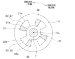
- FIG. 39 shows the state of the inductive sensor 1 when the centers of the bearings 61 and 62 of the housing 6 and the axis CL of the shaft 7 are at the same position and the brake pedal 8 is at the initial position.
- the first target 21 is larger in the radial direction outward than the range in which the first transmitting/receiving coil 31 is mounted on the circuit board 10.
- the second target 22 is larger in the radial direction outward than the range where the second transmitting/receiving coil 32 is mounted on the circuit board 10 .
- the distance F between the radially outer end 21a of the first target 21 and the radially outer end 31a of the first transmitting/receiving coil 31 is greater than the predetermined distance D7.
- the predetermined distance D7 is a distance by which the first target 21 may move relative to the circuit board 10 due to rattling between the bearings 61, 62 of the housing 6 and the shaft 7.
- the distance G between the radially outer end 22a of the second target 22 and the radially outer end 32a of the second transmitting/receiving coil 32 is larger than a predetermined distance.
- the predetermined distance is a distance in which the second target 22 may move relative to the circuit board 10 due to rattling between the bearings 61 and 62 of the housing 6 and the shaft 7.
- the blade portion 212 of the first target 21 is larger inward in the radial direction than the range where the first transmitting/receiving coil 31 is mounted on the circuit board 10.
- the blade portion 222 of the second target is larger inward in the radial direction than the range where the second transmitting/receiving coil 32 is mounted on the circuit board 10 .
- the distance H between the radially inner end 21b of the blade portion 212 of the first target 21 and the radially inner end 31b of the first transmitting/receiving coil 31 is greater than the predetermined distance D8.
- the predetermined distance D8 is a distance by which the first target 21 may move relative to the circuit board 10 due to rattling between the bearings 61 and 62 of the housing 6 and the shaft 7.
- the distance I between the radially inner end 22b of the blade portion 222 of the second target 22 and the radially inner end 32b of the second transmitting/receiving coil 32 is larger than the predetermined distance D9.
- the predetermined distance D9 is a distance by which the second target 22 may move relative to the circuit board 10 due to rattling between the bearings 61 and 62 of the housing 6 and the shaft 7.
- FIG. 41 shows the state of the inductive sensor when the centers of the bearings 61 and 62 of the housing 6 and the axis CL of the shaft 7 are at the same position and the brake pedal 8 is at the initial position.
- the radially outer end 21a of the first target 21 and the radially outer end 31a of the first transmitting/receiving coil 31 are They are located in an overlapping position.
- the radially outer end 22a of the second target 22 and the radially outer end 32a of the second transmitting/receiving coil 32 are located at overlapping positions when viewed from the axial direction.
- FIG. 42 shows a state in which the shaft 7 is eccentric due to rattling between the bearings 61, 62 of the housing 6 and the shaft 7, and the target 20 has moved in the direction shown by the arrow J with respect to the circuit board 10.
- the upper left portion R of the first target 21 in FIG. 42 is out of the mounting range of the first transmitting/receiving coil 31.
- the lower left portion S of the second target 22 in FIG. 42 is also outside the mounting range of the second transmitting/receiving coil 32. Therefore, in the third comparative example, when the shaft 7 is eccentric, the area where the first target 21 and the first transmitting/receiving coil 31 overlap in the axial direction changes greatly. Furthermore, the area where the second target 22 and the second transmitting/receiving coil 32 overlap in the axial direction also varies greatly. Therefore, the amplitude of the signal output from the inductive sensor changes significantly.
- the inductive sensor 1 and brake pedal device 2 of the seventeenth embodiment have the following configuration and the effects thereof in addition to the effects described in the first embodiment etc. be.
- the first target 21 is larger on the radially outer side and the radially inner side than the range where the first transmitting/receiving coil 31 is mounted on the circuit board 10 .
- the second target 22 is larger on the radially outer side and the radially inner side than the range where the second transmitting/receiving coil 32 is mounted on the circuit board 10 . According to this, even if the first target 21 and the second target 22 are eccentric with respect to the circuit board 10 due to, for example, rattling between the bearings 61 and 62 of the housing 6 and the shaft, the range of the first transmitting/receiving coil 31 The first target 21 is always located within.
- the second target 22 is always located within the range of the second transmitting/receiving coil 32. Therefore, the area where the first transmitting/receiving coil 31 and the first target 21 overlap in the axial direction does not change significantly due to the eccentricity of the first target 21 and the second target 22. Furthermore, the area where the second transmitting/receiving coil 32 and the second target 22 overlap in the axial direction does not change significantly. Therefore, the amplitude of the signal output from the inductive sensor 1 does not change significantly.
- the inductive sensor 1 has been described as being applied to the brake pedal device 2, but the inductive sensor 1 is not limited to this, and the inductive sensor 1 can be used in various applications that detect rotating bodies and movable bodies. It can be used for
- the brake pedal device 2 to which the inductive sensor 1 is applied is exemplified as a so-called pendant type, but is not limited to this, and may be, for example, a so-called organ type.
- the pendant type brake pedal is one in which the portion of the brake pedal that is operated by the driver's foot is located below the axis of rotation CL in the direction of gravity when mounted on a vehicle.
- the organ type brake pedal is one in which, when installed in a vehicle, the portion of the brake pedal operated by the driver's foot is located above the rotational axis CL in the direction of gravity.
- the brake pedal device 2 to which the inductive sensor 1 is applied is described as being used in a complete brake-by-wire system 5, but the invention is not limited to this.
- the brake pedal device 2 is also used for a brake-by-wire system 5 in which the components of the brake mechanism 4 and the brake pedal are mechanically connected, and in which the ECU 3 drives the brake mechanism 4 based on the output signal of the inductive sensor 1. It is also possible.
- a component of the brake mechanism 4 is, for example, a master cylinder.
- the inductive sensor 1 was described as detecting the position (specifically, the rotation angle) of the shaft 7 and the brake pedal 8, but the invention is not limited to this.
- the inductive sensor 1 may detect the stroke amount of the brake pedal 8, for example.
- the inductive sensor 1 may detect the amount of operation of the reaction force generating mechanism 9, etc.
- the inductive sensor 1 has been described as having two targets 20, but the inductive sensor 1 is not limited thereto, and may have three or more targets 20. Further, in the ninth embodiment, the inductive sensor 1 has been described as having a plurality of circuit boards 11 and 12, but the present invention is not limited thereto, and the inductive sensor 1 may have three or more circuit boards 10.
- the anti-rotation structure has the first hole 214 and the second hole 224 of the target 20 having a non-circular shape when viewed from the axial direction, that is, a non-circular shape, and the outer wall of the shaft 7 is fitted into the non-circular shape. It is also possible to have a matching shape.
- the present disclosure is not limited to the embodiments described above, and can be modified as appropriate. Furthermore, the above-described embodiments and parts thereof are not unrelated to each other, and can be combined as appropriate, except in cases where combinations are clearly impossible. Furthermore, in each of the above embodiments, it goes without saying that the elements constituting the embodiments are not necessarily essential, except in cases where it is specifically stated that they are essential or where they are clearly considered essential in principle. stomach. In addition, in each of the above embodiments, when numerical values such as the number, numerical value, amount, range, etc. of the constituent elements of the embodiment are mentioned, when it is clearly stated that it is essential, or when it is clearly limited to a specific number in principle. It is not limited to that specific number, except in cases where In addition, in each of the above embodiments, when referring to the shape, positional relationship, etc. of constituent elements, etc., the shape, It is not limited to positional relationships, etc.
- the detection target is a rotating body (7) that is rotatably provided around a predetermined axis (CL) with respect to the fixed body (6) or a movable body (8) that moves in accordance with the movement of the rotating body.
- Transmitting/receiving coils (30, 31, 32) including a transmitting coil and a receiving coil, and a receiving/transmitting circuit (35) that supplies a high frequency to the transmitting coil and outputs a signal according to a change in inductance of the receiving coil are implemented.
- An inductive sensor comprising: a plurality of targets (20, 21, 22) that move in synchronization with the movement of the detection target and include a conductor (25).
- the plurality of targets include at least a first target (21) and a second target (22),
- the transmitting/receiving coil includes a first transmitting/receiving coil (31) that outputs a detected value according to the position of the first target, and a second transmitting/receiving coil (32) that outputs a detected value according to the position of the second target.
- the inductive sensor according to the first aspect, having at least the following.
- the inductive sensor according to the second aspect wherein a distance (D3) between the first target and the first transmitting/receiving coil and a distance (D4) between the second target and the second transmitting/receiving coil are the same.
- the first transmitting/receiving coil is mounted on one surface of one of the circuit boards, and the second transmitting/receiving coil is mounted on the other surface of the circuit board,
- the first target is arranged on one side of the circuit board in the thickness direction
- the second target is arranged on the other side of the circuit board in the thickness direction. Inductive sensor.
- a surface (210) of the first target facing the first transmitting/receiving coil and a surface (220) of the second target facing the second transmitting/receiving coil are arranged on a first virtual plane (VS1). is, The first transmitting/receiving coil and the second transmitting/receiving coil are arranged on a second or third virtual plane (VS2) parallel to the first virtual plane on the circuit board.
- At least one of the plurality of targets has at least a portion of the portion facing the transmitting/receiving coil formed of the conductive material, and the remaining portion formed of the insulating material (26).
- the inductive sensor according to any one of the fifth aspects.
- the inductive sensor according to the sixth aspect wherein the insulator forming a part of the target is a resin, and the resin is used for a portion (211, 221) where the target is fixed to the detection object.
- the plurality of targets include at least a first target (21) and a second target (22),
- a shaft (7) as the rotating body is inserted into a first hole (214) of the first target and a second hole (224) of the second target,
- the inductive sensor according to the eighth aspect further comprising a rotation prevention structure that restricts relative rotation between the first target and the shaft, and restricts relative rotation between the second target and the shaft.
- the plurality of targets include at least a first target and a second target,
- the range in which the first transmitting/receiving coil is mounted on the circuit board is on one side and the other side in the movable direction of the first target, beyond the movable range of the first target that moves in synchronization with the movement of the detection target.
- the range in which the second transmitting/receiving coil is mounted on the circuit board is on one side and the other side in the movable direction of the second target, beyond the movable range of the second target that moves in synchronization with the movement of the detection target.
- the inductive sensor according to any one of the second to tenth aspects, which is large.
- the first target is larger on the radially outer side and the radially inner side of a virtual circle perpendicular to the axial center and centered on the axial center than the range in which the first transmitting/receiving coil is mounted on the circuit board
- the second target is located in any one of the second to eleventh aspects, which is larger on the radially outer side and the radially inner side of the virtual circle than the range in which the second transmitter/receiver coil is mounted on the circuit board.
- a brake pedal device (2) used in a brake-by-wire system (5) in which a brake mechanism (4) brakes the vehicle under drive control of an electronic control device (3) mounted on the vehicle
- the inductive sensor (1) according to any one of the first to seventh aspects, a housing (6) as the fixed body fixed directly or indirectly to the vehicle body; a shaft (7) as the rotating body that is rotatably provided in a predetermined angular range with respect to the housing; a brake pedal (8) as the movable body that is fixed to the shaft and operates in a predetermined angular range around the axis (CL) of the shaft;
- a brake pedal device comprising: a reaction force generation mechanism (9) that generates a reaction force against a driver's pedal force applied to the brake pedal.
- the brake pedal device according to the thirteenth aspect, which is used in a brake-by-wire system.
- the plurality of targets include at least a first target (21) and a second target (22), the first target is fixed to the shaft, The brake pedal device according to the thirteenth or fourteenth aspect, wherein the second target is fixed to the brake pedal.
- the plurality of targets are fixed to the shaft, Further comprising a torsion spring (41) that applies a load to at least one of the plurality of targets in a circumferential direction around the axis, One end (42) of the torsion spring is locked to at least one of the plurality of targets, and the other end (43) of the torsion spring is locked to the fixed body.
- the brake pedal device according to any one of the fifteenth aspects.
- the plurality of targets include at least a first target (21) and a second target (22), The brake pedal device according to the thirteenth or fourteenth aspect, wherein both the first target and the second target are fixed to the shaft with the same bolt (75).
- the shaft is inserted into a first hole (214) of the first target and a second hole (224) of the second target,
- the brake pedal device according to the seventeenth aspect, further comprising a detent structure that restricts relative rotation between the first target and the shaft and restricts relative rotation between the second target and the shaft.
- the plurality of targets include at least a first target and a second target,
- the inductive sensor according to the thirteenth or fourteenth aspect, wherein both the first target and the second target are fixed to the shaft by caulking (701).
- the plurality of targets include at least a first target and a second target
- the transmitting/receiving coil includes a first transmitting/receiving coil (31) that outputs a detected value according to the position of the first target, and a second transmitting/receiving coil (32) that outputs a detected value according to the position of the second target.
- the brake pedal device according to any one of the thirteenth to nineteenth aspects.
- the plurality of targets include at least a first target and a second target
- the transmitting/receiving coil has at least a first transmitting/receiving coil that outputs a detected value according to the position of the first target, and a second transmitting/receiving coil that outputs a detected value according to the position of the second target
- the first target is larger on the radially outer side and the radially inner side of a virtual circle perpendicular to the axial center and centered on the axial center than the range in which the first transmitting/receiving coil is mounted on the circuit board
- the second target is larger on the radially outer side and the radially inner side of the virtual circle than the range in which the second transmitter/receiver coil is mounted on the circuit board.
- Brake pedal device as described.
Landscapes
- Engineering & Computer Science (AREA)
- Transportation (AREA)
- Mechanical Engineering (AREA)
- Physics & Mathematics (AREA)
- General Physics & Mathematics (AREA)
- Mechanical Control Devices (AREA)
- Measurement Of Length, Angles, Or The Like Using Electric Or Magnetic Means (AREA)
- Braking Arrangements (AREA)
Abstract
Description
本開示は上記点に鑑みて、検出対象の位置検出の冗長性を確保することの可能なインダクティブセンサを提供することを目的とする。また、本開示は、そのインダクティブセンサを備えたブレーキペダル装置を提供することを目的とする。
第1実施形態について図面を参照しつつ説明する。図1に示すように、第1実施形態のインダクティブセンサ1は、車両に搭載されるブレーキペダル装置2に適用されるものである。このブレーキペダル装置2は、車両に搭載される電子制御装置(以下、「ECU3」という)の駆動制御によりブレーキ機構4が車両の制動を行うブレーキバイワイヤシステム5に用いられるものである。なお、ECUはElectronic Control Unitの略である。特に、第1実施形態のインダクティブセンサ1が適用されるブレーキペダル装置2は、完全なブレーキバイワイヤシステム5に用いられるものである。完全なブレーキバイワイヤシステム5とは、ブレーキ機構4の構成部材とブレーキペダルとが機械的に接続されておらず、インダクティブセンサ1の出力信号に基づいてECU3がブレーキ機構4を駆動制御して車両の制動を行うシステムである。ブレーキ機構4の構成部材は、例えばマスターシリンダが相当する。
図1~図4に示すように、ブレーキペダル装置2は、ハウジング6、シャフト7、ブレーキペダル8、反力発生機構9、インダクティブセンサ1などを備えている。
これによれば、複数のターゲット20のうち1個のターゲット20が脱落または変形等した場合でも、別のターゲット20と送受信コイル30により、検出対象の位置を正しく検出することが可能である。したがって、インダクティブセンサ1は、ターゲット20の脱落または変形等に対し、検出対象の位置検出の冗長性を確保することができる。
これによれば、ブレーキバイワイヤシステム5では、ブレーキペダル装置2のシャフト7およびブレーキペダル8の位置検出を行うインダクティブセンサ1が機能失陥すると、車両の制動に支障が出る恐れがある。それに対し、第1実施形態のブレーキペダル装置2は、インダクティブセンサ1が複数のターゲット20を備えているので、ターゲット20の脱落または変形等に対して、シャフト7およびブレーキペダル8の位置検出の冗長性を確保することが可能である。したがって、このブレーキペダル装置2は、ブレーキバイワイヤシステム5による車両制動の安全性を高めることができる。
第2実施形態について説明する。第2実施形態は、第1実施形態に対してインダクティブセンサ1の構成を変更したものであり、その他については第1実施形態と同様であるため、第1実施形態と異なる部分についてのみ説明する。
これによれば、インダクティブセンサ1は、第1ターゲット21と第1送受信コイル31により構成される第1センサ部と、第2ターゲット22と第2送受信コイル32により構成される第2センサ部とを備えるものとなる。そのため、第1センサ部および第2センサ部の一方のセンサ部が機能失陥または脱落した場合でも、他方のセンサ部により検出対象の位置を正しく検出することが可能である。したがって、インダクティブセンサ1は、ターゲット20の脱落または変形等に対して、検出対象の位置検出の冗長性を確保することができる。
これによれば、検出対象の位置検出に関し、第1センサ部の検出値と第2センサ部の検出値とを実質的に同一にすることが可能である。そのため、インダクティブセンサ1の検出値が伝送されるECU3において、第1センサ部の検出値と第2センサ部の検出値の信号後処理を無しにするか又は簡素なものとして、その2つの検出値を容易に比較することが可能となる。
このような構成により、第1ターゲット21と第1送受信コイル31との距離D3と、第2ターゲット22と第2送受信コイル32との距離D4とを同一にすることが可能である。
第3実施形態について説明する。第3実施形態は、第2実施形態等に対してインダクティブセンサ1が備えるターゲットの固定方法を変更したものであり、その他については第2実施形態と同様であるため、第2実施形態と異なる部分についてのみ説明する。
第4実施形態について説明する。第4実施形態は、第1実施形態等に対してインダクティブセンサ1の構成を変更したものであり、その他については第1実施形態等と同様であるため、第1実施形態等と異なる部分についてのみ説明する。
このような配置により、第4実施形態でも、第1ターゲット21と第1送受信コイル31との距離D3と、第2ターゲット22と第2送受信コイル32との距離D4とを同一にすることが可能である。そのため、第1ターゲット21または第2ターゲット22のいずれか一方のターゲット20がシャフト7から何らかの原因で脱落し、他方のターゲット20により検出対象の位置を検出する場合でも、センサ出力の信号振幅が小さくなることが無い。信号振幅が大きければ、SN比(即ち、信号対雑音比)が大きくなり、伝送におけるノイズの影響が小さくなるので、検出対象の位置を高精度に検出できる。
第5実施形態について説明する。第5実施形態も、第1実施形態等に対してインダクティブセンサ1の構成を変更したものであり、その他については第1実施形態等と同様であるため、第1実施形態等と異なる部分についてのみ説明する。
第6実施形態について説明する。第6実施形態も、第1実施形態等に対してインダクティブセンサ1の構成を変更したものであり、その他については第1実施形態等と同様であるため、第1実施形態等と異なる部分についてのみ説明する。
これによれば、ターゲット20のうち、磁界をキャンセルする機能を必要とする部位を導電体25で形成し、残りの部位をコストの安い絶縁体材料を選択して形成できる。
これによれば、仮にターゲット20の全部を導電体25としての金属で形成すると、ターゲット20のうち検出対象に固定される部位が錆びて、ターゲット20が検出対象から脱落する恐れがある。それに対し、第6実施形態では、ターゲット20のうち検出対象に固定される部位を樹脂とすることで、ターゲット20が錆などで脱落することを防ぐことができる。
さらに、ターゲット20のうち検出対象に固定される部位が複雑な形状であっても、樹脂であれば射出成形により、容易に作ることができる。
すなわち、ターゲット20を2つ以上備えている場合、ターゲット20の全部を導電体25(例えば、アルミ)で形成したものと、ターゲット20のうち検出対象に固定される部位を絶縁体(例えば、樹脂)で形成したものにより2種類又はそれ以上とする。
その理由は、仮に、2つのターゲット20両方ともアルミで形成した場合、2つとも同じ要因で腐食する恐れがある。また、仮に、2つターゲット20を両方とも樹脂で形成した場合、高温時にターゲット20のうち検出対象に固定される部位がクリープしてシャフト7への固定力が弱まり2つとも脱落してしまう恐れがある。
それに対し、ターゲット20を2つ以上備えている場合、ターゲット20の全部を導電体25(例えば、アルミ)で形成したものと、ターゲット20のうち検出対象に固定される部位を絶縁体(例えば、樹脂)で形成したものにより2種類又はそれ以上とする。これにより、同一原因により全部のターゲット20が脱落することが防がれるので、さらに固定冗長化できる。
第7実施形態について説明する。第7実施形態も、第1実施形態等に対してインダクティブセンサ1の構成を変更したものであり、その他については第1実施形態等と同様であるため、第1実施形態等と異なる部分についてのみ説明する。
これによれば、ターゲット20が、仮に、軸心CLを中心とした周方向に微小なズレ幅を有している場合でも、トーションスプリング41の付勢力によりターゲット20がその周方向の一方側に押し付けられるので、ターゲット20がガタつくことが防がれる。
第8実施形態について説明する。第8実施形態は、第1実施形態の変形例である。
図23に示すように、第8実施形態のインダクティブセンサ1も、回路基板10と複数のターゲット20を備えている。複数のターゲット20のうち第1ターゲット21は、検出対象としての回転体(例えば、シャフト7)と同期して動作する部材80に固定されている。なお、その部材80は、例えば、ペダルアーム81またはそこに接続された部品(例えば、第3実施形態で説明した腕部83)である。複数のターゲット20のうち第2ターゲット22は、回転体(例えば、シャフト7)に固定されている。
第9実施形態について説明する。第9実施形態は、第1実施形態の変形例である。
図25~図27に示すように、第10実施形態では、ブレーキペダル装置2が備えるシャフト7の回転の軸心CLと、インダクティブセンサ1が備える複数のターゲット20の回転の軸心SCとが異なる位置にあるものを例示する。以下の説明では、ターゲット20の回転の軸心SCを、「センサ軸心SC」という。
第11実施形態について説明する。第11実施形態は、第1実施形態等に対して、複数のターゲット20の固定方法の一例を説明するものである。
第11実施形態で説明した複数のターゲット20と検出対象との固定方法は、第1~第17実施形態に適用可能である。
第12実施形態について説明する。第12実施形態も、第1実施形態等に対して、複数のターゲット20の固定方法の一例を説明するものである。
これによれば、第1ターゲット21と第2ターゲット22をシャフト7に対し、特別な設備を必要とせずに容易に固定できる。
これによれば、仮にボルト75が緩んだ場合でも、第1ターゲット21および第2ターゲット22とシャフト7とが相対回転してしまうことが無い。そのため、インダクティブセンサ1は、検出対象としてのシャフト7およびブレーキペダル8の位置を引き続き正しく検出でき、検出対象の位置検出の冗長性を確保できる。
第13実施形態について説明する。第13実施形態は、第12実施形態に対して、回り止め構造の別の具体例を説明するものである。
第14実施形態について説明する。第14実施形態も、第12実施形態に対して、回り止め構造の別の具体例を説明するものである。
第15実施形態について説明する。第15実施形態は、第12~第14実施形態に対し、複数のターゲット20の固定方法を変更したものである。
これによれば、第1ターゲット21と第2ターゲット22をシャフト7に対しボルト75で固定する構成と比べて、ボルト75の部品コストを低減できる。また、一般に、かしめ701の頭の高さは、ボルト75の頭の高さよりも低いので、図29で示した第1の仮想平面VS1上にターゲット20の検出面を配置するために必要なターゲット20の曲げ量(即ち、腕部223、223の長さ)を小さくできる。したがって、インダクティブセンサ1の軸心方向の体格を小型化できる。なお、ターゲット20の検出面とは、第1ターゲット21の有する複数の羽根部212のうち第1送受信コイル31を向く面210、および、第2ターゲット22の有する複数の羽根部222のうち第2送受信コイル32を向く面220である。
第16実施形態について説明する。第16実施形態は、第5、第12~第15実施形態に対し、送受信コイル30の大きさについて変更したものである。
そのため、第2比較例では、ブレーキペダル8が初期位置にあるときにシャフト7が偏心した場合、第1ターゲット21と第1送受信コイル31とが軸心方向に重なる面積が大きく変わる。また、第2ターゲット22と第2送受信コイル32とが軸心方向に重なる面積も大きく変わる。したがって、インダクティブセンサから出力される信号の振幅が大きく変わってしまう。
これによれば、例えばハウジング6の軸受61、62とシャフト7とのがたつきにより、第1ターゲット21と第2ターゲット22が回路基板10に対して偏心した場合でも、第1送受信コイル31の範囲内に第1ターゲット21が常に位置する。また、第2送受信コイル32の範囲内に第2ターゲット22が常に位置する。そのため、第1ターゲット21と第2ターゲット22の偏心により第1送受信コイル31と第1ターゲット21とが軸心方向に重なる面積は大きく変わらない。また、第2送受信コイル32と第2ターゲット22とが軸心方向に重なる面積も大きく変わらない。したがって、インダクティブセンサ1から出力される信号の振幅が大きく変わることが無い。
第17実施形態について説明する。第17実施形態は、第5、第12~第16実施形態に対し、ターゲット20の大きさについて変更したものである。
これによれば、例えばハウジング6の軸受61、62とシャフトとのがたつきにより、第1ターゲット21と第2ターゲット22が回路基板10に対して偏心した場合でも、第1送受信コイル31の範囲内に第1ターゲット21が常に位置する。また、第2送受信コイル32の範囲内に第2ターゲット22が常に位置する。そのため、第1ターゲット21と第2ターゲット22の偏心により第1送受信コイル31と第1ターゲット21とが軸心方向に重なる面積は大きく変わらない。また、第2送受信コイル32と第2ターゲット22とが軸心方向に重なる面積も大きく変わらない。したがって、インダクティブセンサ1から出力される信号の振幅が大きく変わることが無い。
(1)上記各実施形態では、インダクティブセンサ1はブレーキペダル装置2に適用されるものとして説明したが、これに限らず、インダクティブセンサ1は、回転体および可動体を検出対象とした種々の用途に用いることが可能である。
[第1の観点]
固定体(6)に対して所定の軸心(CL)まわりに回転可能に設けられた回転体(7)または前記回転体の運動に伴って動作する可動体(8)を検出対象として、前記固定体に対する前記検出対象の位置を検出するインダクティブセンサにおいて、
送信コイルおよび受信コイルを含む送受信コイル(30、31、32)と、前記送信コイルに高周波を供給し前記受信コイルのインダクタンスの変化に応じた信号を出力する受発信回路(35)とが実装され、前記固定体に固定された回路基板(10、11、12)と、
前記検出対象の運動に同期して動き、導電体(25)を含んで構成されている複数のターゲット(20、21、22)と、を備えるインダクティブセンサ。
[第2の観点]
複数の前記ターゲットは、第1ターゲット(21)と第2ターゲット(22)とを少なくとも有し、
前記送受信コイルは、前記第1ターゲットの位置に応じた検出値を出力する第1送受信コイル(31)と、前記第2ターゲットの位置に応じた検出値を出力する第2送受信コイル(32)とを少なくとも有している、第1の観点に記載のインダクティブセンサ。
[第3の観点]
前記第1ターゲットと前記第1送受信コイルとの距離(D3)と、前記第2ターゲットと前記第2送受信コイルとの距離(D4)とは同一である、第2の観点に記載のインダクティブセンサ。
[第4の観点]
1個の前記回路基板の一方の面に前記第1送受信コイルが実装され、前記回路基板の他方の面に前記第2送受信コイルが実装され、
前記回路基板の板厚方向の一方側に前記第1ターゲットが配置され、前記回路基板の板厚方向の他方側に前記第2ターゲットが配置されている、第2または第3の観点に記載のインダクティブセンサ。
[第5の観点]
前記第1ターゲットのうち前記第1送受信コイルを向く面(210)と、前記第2ターゲットのうち前記第2送受信コイルを向く面(220)とは、第1の仮想平面(VS1)上に配置され、
前記第1送受信コイルと前記第2送受信コイルとは、前記回路基板において前記第1の仮想平面と平行な第2の仮想平面(VS2)上に配置されている、第2または第3の観点に記載のインダクティブセンサ。
[第6の観点]
複数の前記ターゲットのうち少なくとも1つの前記ターゲットは、前記送受信コイルに対向する部位の少なくとも一部が前記導電体で形成され、残りの部位が絶縁体(26)で形成されている、第1ないし第5の観点のいずれか1つに記載のインダクティブセンサ。
[第7の観点]
前記ターゲットの一部を形成する前記絶縁体は樹脂であり、前記樹脂は前記ターゲットが前記検出対象に固定される部位(211、221)に用いられる、第6の観点に記載のインダクティブセンサ。
[第8の観点]
複数の前記ターゲットは、第1ターゲット(21)と第2ターゲット(22)とを少なくとも有し、
前記第1ターゲットと前記第2ターゲットとは共に、同じボルト(75)で前記回転体に固定されている第1ないし第7の観点のいずれか1つに記載のインダクティブセンサ。
[第9の観点]
前記第1ターゲットの有する第1孔(214)と前記第2ターゲットの有する第2孔(224)に対し、前記回転体としてのシャフト(7)が挿入されており、
前記第1ターゲットと前記シャフトとの相対回転を規制し、前記第2ターゲットと前記シャフトとの相対回転を規制する回り止め構造をさらに備える第8の観点に記載のインダクティブセンサ。
[第10の観点]
複数の前記ターゲットは、第1ターゲットと第2ターゲットとを少なくとも有し、
前記第1ターゲットと前記第2ターゲットとは共に、かしめ(701)により前記回転体に固定されている第1ないし第7の観点のいずれか1つに記載のインダクティブセンサ。
[第11の観点]
前記回路基板に前記第1送受信コイルが実装される範囲は、前記検出対象の運動に同期して可動する前記第1ターゲットの可動範囲よりも前記第1ターゲットの可動方向の一方側および他方側に大きく、
前記回路基板に前記第2送受信コイルが実装される範囲は、前記検出対象の運動に同期して可動する前記第2ターゲットの可動範囲よりも前記第2ターゲットの可動方向の一方側および他方側に大きい、第2ないし第10の観点のいずれか1つに記載のインダクティブセンサ。
[第12の観点]
前記第1ターゲットは、前記回路基板に前記第1送受信コイルが実装される範囲よりも、前記軸心に垂直且つ前記軸心を中心とした仮想円の径方向外側および径方向内側に大きく、
前記第2ターゲットは、前記回路基板に前記第2送受信コイルが実装される範囲よりも、前記仮想円の径方向外側および径方向内側に大きい、第2ないし第11の観点のいずれか1つに記載のインダクティブセンサ。
[第13の観点]
車両に搭載される電子制御装置(3)の駆動制御によりブレーキ機構(4)が前記車両の制動を行うブレーキバイワイヤシステム(5)に使用されるブレーキペダル装置(2)において、
第1ないし第7の観点のいずれか1つに記載の前記インダクティブセンサ(1)と、
車体に直接または間接的に固定される前記固定体としてのハウジング(6)と、
前記ハウジングに対して所定の角度範囲で回転可能に設けられた前記回転体としてのシャフト(7)と、
前記シャフトに固定されて、前記シャフトの軸心(CL)まわりに所定の角度範囲で動作する前記可動体としてのブレーキペダル(8)と、
前記ブレーキペダルに印加される運転者の踏力に対する反力を発生させる反力発生機構(9)と、を備えるブレーキペダル装置。
[第14の観点]
前記ブレーキ機構の構成部材と前記ブレーキペダルとが機械的に接続されておらず、前記インダクティブセンサの出力信号に基づいて前記電子制御装置が前記ブレーキ機構を駆動制御して前記車両の制動を行う完全なブレーキバイワイヤシステムに用いられるものである、第13の観点に記載のブレーキペダル装置。
[第15の観点]
複数の前記ターゲットは、少なくとも第1ターゲット(21)と第2ターゲット(22)とを有し、
前記第1ターゲットは、前記シャフトに固定され、
前記第2ターゲットは、前記ブレーキペダルに固定されている、第13または第14の観点に記載のブレーキペダル装置。
[第16の観点]
複数の前記ターゲットは前記シャフトに固定されており、
複数の前記ターゲットのうち少なくとも1つの前記ターゲットに対して前記軸心を中心とした周方向に荷重を印加するトーションスプリング(41)をさらに備え、
前記トーションスプリングの一端(42)は、複数の前記ターゲットのうち少なくとも1つの前記ターゲットに係止され、前記トーションスプリングの他端(43)は、前記固定体に係止されている、第13ないし第15の観点のいずれか1つに記載のブレーキペダル装置。
[第17の観点]
複数の前記ターゲットは、第1ターゲット(21)と第2ターゲット(22)とを少なくとも有し、
前記第1ターゲットと前記第2ターゲットとは共に、同じボルト(75)で前記シャフトに固定されている第13または第14の観点に記載のブレーキペダル装置。
[第18の観点]
前記第1ターゲットの有する第1孔(214)と前記第2ターゲットの有する第2孔(224)に対し、前記シャフトが挿入されており、
前記第1ターゲットと前記シャフトとの相対回転を規制し、前記第2ターゲットと前記シャフトとの相対回転を規制する回り止め構造をさらに備える第17の観点に記載のブレーキペダル装置。
[第19の観点]
複数の前記ターゲットは、第1ターゲットと第2ターゲットとを少なくとも有し、
前記第1ターゲットと前記第2ターゲットとは共に、かしめ(701)により前記シャフトに固定されている第13または第14の観点に記載のインダクティブセンサ。
[第20の観点]
複数の前記ターゲットは、第1ターゲットと第2ターゲットとを少なくとも有し、
前記送受信コイルは、前記第1ターゲットの位置に応じた検出値を出力する第1送受信コイル(31)と、前記第2ターゲットの位置に応じた検出値を出力する第2送受信コイル(32)とを少なくとも有し、
前記回路基板に前記第1送受信コイルが実装される範囲は、前記シャフトと同期して回転する前記第1ターゲットの回転範囲よりも前記第1ターゲットの回転方向の一方側および他方側に大きく、
前記回路基板に前記第2送受信コイルが実装される範囲は、前記シャフトと同期して回転する前記第2ターゲットの回転範囲よりも前記第2ターゲットの回転方向の一方側および他方側に大きい、第13ないし第19の観点のいずれか1つに記載のブレーキペダル装置。
[第21の観点]
複数の前記ターゲットは、第1ターゲットと第2ターゲットとを少なくとも有し、
前記送受信コイルは、前記第1ターゲットの位置に応じた検出値を出力する第1送受信コイルと、前記第2ターゲットの位置に応じた検出値を出力する第2送受信コイルとを少なくとも有し、
前記第1ターゲットは、前記回路基板に前記第1送受信コイルが実装される範囲よりも、前記軸心に垂直且つ前記軸心を中心とした仮想円の径方向外側および径方向内側に大きく、
前記第2ターゲットは、前記回路基板に前記第2送受信コイルが実装される範囲よりも、前記仮想円の径方向外側および径方向内側に大きい、第13ないし第20の観点のいずれか1つに記載のブレーキペダル装置。
Claims (21)
- 固定体(6)に対して所定の軸心(CL)まわりに回転可能に設けられた回転体(7)または前記回転体の運動に伴って動作する可動体(8)を検出対象として、前記固定体に対する前記検出対象の位置を検出するインダクティブセンサにおいて、
送信コイルおよび受信コイルを含む送受信コイル(30、31、32)と、前記送信コイルに高周波を供給し前記受信コイルのインダクタンスの変化に応じた信号を出力する受発信回路(35)とが実装され、前記固定体に固定された回路基板(10、11、12)と、
前記検出対象の運動に同期して動き、導電体(25)を含んで構成されている複数のターゲット(20、21、22)と、を備えるインダクティブセンサ。 - 複数の前記ターゲットは、第1ターゲット(21)と第2ターゲット(22)とを少なくとも有し、
前記送受信コイルは、前記第1ターゲットの位置に応じた検出値を出力する第1送受信コイル(31)と、前記第2ターゲットの位置に応じた検出値を出力する第2送受信コイル(32)とを少なくとも有している、請求項1に記載のインダクティブセンサ。 - 前記第1ターゲットと前記第1送受信コイルとの距離(D3)と、前記第2ターゲットと前記第2送受信コイルとの距離(D4)とは同一である、請求項2に記載のインダクティブセンサ。
- 1個の前記回路基板の一方の面に前記第1送受信コイルが実装され、前記回路基板の他方の面に前記第2送受信コイルが実装され、
前記回路基板の板厚方向の一方側に前記第1ターゲットが配置され、前記回路基板の板厚方向の他方側に前記第2ターゲットが配置されている、請求項3に記載のインダクティブセンサ。 - 前記第1ターゲットのうち前記第1送受信コイルを向く面(210)と、前記第2ターゲットのうち前記第2送受信コイルを向く面(220)とは、第1の仮想平面(VS1)上に配置され、
前記第1送受信コイルと前記第2送受信コイルとは、前記回路基板において前記第1の仮想平面と平行な第2の仮想平面(VS2)上に配置されている、請求項2に記載のインダクティブセンサ。 - 複数の前記ターゲットのうち少なくとも1つの前記ターゲットは、前記送受信コイルに対向する部位の少なくとも一部が前記導電体で形成され、残りの部位が絶縁体(26)で形成されている、請求項1に記載のインダクティブセンサ。
- 前記ターゲットの一部を形成する前記絶縁体は樹脂であり、前記樹脂は前記ターゲットが前記検出対象に固定される部位(211、221)に用いられる、請求項6に記載のインダクティブセンサ。
- 複数の前記ターゲットは、第1ターゲット(21)と第2ターゲット(22)とを少なくとも有し、
前記第1ターゲットと前記第2ターゲットとは共に、同じボルト(75)で前記回転体に固定されている請求項1に記載のインダクティブセンサ。 - 前記第1ターゲットの有する第1孔(214)と前記第2ターゲットの有する第2孔(224)に対し、前記回転体としてのシャフト(7)が挿入されており、
前記第1ターゲット(21)と前記シャフトとの相対回転を規制し、前記第2ターゲット(22)と前記シャフトとの相対回転を規制する回り止め構造をさらに備える請求項8に記載のインダクティブセンサ。 - 複数の前記ターゲットは、第1ターゲットと第2ターゲットとを少なくとも有し、
前記第1ターゲットと前記第2ターゲットとは共に、かしめ(701)により前記回転体に固定されている請求項1に記載のインダクティブセンサ。 - 前記回路基板に前記第1送受信コイルが実装される範囲は、前記検出対象の運動に同期して可動する前記第1ターゲットの可動範囲よりも前記第1ターゲットの可動方向の一方側および他方側に大きく、
前記回路基板に前記第2送受信コイルが実装される範囲は、前記検出対象の運動に同期して可動する前記第2ターゲットの可動範囲よりも前記第2ターゲットの可動方向の一方側および他方側に大きい、請求項2に記載のインダクティブセンサ。 - 前記第1ターゲットは、前記回路基板に前記第1送受信コイルが実装される範囲よりも、前記軸心に垂直且つ前記軸心を中心とした仮想円の径方向外側および径方向内側に大きく、
前記第2ターゲットは、前記回路基板に前記第2送受信コイルが実装される範囲よりも、前記仮想円の径方向外側および径方向内側に大きい、請求項2に記載のインダクティブセンサ。 - 車両に搭載される電子制御装置(3)の駆動制御によりブレーキ機構(4)が前記車両の制動を行うブレーキバイワイヤシステム(5)に使用されるブレーキペダル装置(2)において、
請求項1に記載の前記インダクティブセンサ(1)と、
車体に直接または間接的に固定される前記固定体としてのハウジング(6)と、
前記ハウジングに対して所定の角度範囲で回転可能に設けられた前記回転体としてのシャフト(7)と、
前記シャフトに固定されて、前記シャフトの軸心(CL)まわりに所定の角度範囲で動作する前記可動体としてのブレーキペダル(8)と、
前記ブレーキペダルに印加される運転者の踏力に対する反力を発生させる反力発生機構(9)と、を備えるブレーキペダル装置。 - 前記ブレーキ機構の構成部材と前記ブレーキペダルとが機械的に接続されておらず、前記インダクティブセンサの出力信号に基づいて前記電子制御装置が前記ブレーキ機構を駆動制御して前記車両の制動を行う完全なブレーキバイワイヤシステムに用いられるものである、請求項13に記載のブレーキペダル装置。
- 複数の前記ターゲットは、少なくとも第1ターゲット(21)と第2ターゲット(22)とを有し、
前記第1ターゲットは、前記シャフトに固定され、
前記第2ターゲットは、前記ブレーキペダルに固定されている、請求項13に記載のブレーキペダル装置。 - 複数の前記ターゲットは前記シャフトに固定されており、
複数の前記ターゲットのうち少なくとも1つの前記ターゲットに対して前記軸心を中心とした周方向に荷重を印加するトーションスプリング(41)をさらに備え、
前記トーションスプリングの一端(42)は、複数の前記ターゲットのうち少なくとも1つの前記ターゲットに係止され、前記トーションスプリングの他端(43)は、前記固定体に係止されている、請求項13に記載のブレーキペダル装置。 - 複数の前記ターゲットは、第1ターゲット(21)と第2ターゲット(22)とを少なくとも有し、
前記第1ターゲットと前記第2ターゲットとは共に、同じボルト(75)で前記シャフトに固定されている請求項13に記載のブレーキペダル装置。 - 前記第1ターゲットの有する第1孔(214)と前記第2ターゲットの有する第2孔(224)に対し、前記シャフトが挿入されており、
前記第1ターゲットと前記シャフトとの相対回転を規制し、前記第2ターゲットと前記シャフトとの相対回転を規制する回り止め構造をさらに備える請求項17に記載のブレーキペダル装置。 - 複数の前記ターゲットは、第1ターゲットと第2ターゲットとを少なくとも有し、
前記第1ターゲットと前記第2ターゲットとは共に、かしめ(701)により前記シャフトに固定されている請求項13に記載のインダクティブセンサ。 - 複数の前記ターゲットは、第1ターゲットと第2ターゲットとを少なくとも有し、
前記送受信コイルは、前記第1ターゲットの位置に応じた検出値を出力する第1送受信コイル(31)と、前記第2ターゲットの位置に応じた検出値を出力する第2送受信コイル(32)とを少なくとも有し、
前記回路基板に前記第1送受信コイルが実装される範囲は、前記シャフトと同期して回転する前記第1ターゲットの回転範囲よりも前記第1ターゲットの回転方向の一方側および他方側に大きく、
前記回路基板に前記第2送受信コイルが実装される範囲は、前記シャフトと同期して回転する前記第2ターゲットの回転範囲よりも前記第2ターゲットの回転方向の一方側および他方側に大きい、請求項13に記載のブレーキペダル装置。 - 複数の前記ターゲットは、第1ターゲットと第2ターゲットとを少なくとも有し、
前記送受信コイルは、前記第1ターゲットの位置に応じた検出値を出力する第1送受信コイルと、前記第2ターゲットの位置に応じた検出値を出力する第2送受信コイルとを少なくとも有し、
前記第1ターゲットは、前記回路基板に前記第1送受信コイルが実装される範囲よりも、前記軸心に垂直且つ前記軸心を中心とした仮想円の径方向外側および径方向内側に大きく、
前記第2ターゲットは、前記回路基板に前記第2送受信コイルが実装される範囲よりも、前記仮想円の径方向外側および径方向内側に大きい、請求項13に記載のブレーキペダル装置。
Priority Applications (4)
| Application Number | Priority Date | Filing Date | Title |
|---|---|---|---|
| JP2024518073A JP7613637B2 (ja) | 2022-04-29 | 2023-04-28 | インダクティブセンサ、および、ブレーキペダル装置 |
| CN202380035262.9A CN119053835A (zh) | 2022-04-29 | 2023-04-28 | 电感式传感器及制动踏板装置 |
| DE112023002163.5T DE112023002163T5 (de) | 2022-04-29 | 2023-04-28 | Induktiver sensor und bremspedalvorrichtung |
| US18/904,909 US20250026320A1 (en) | 2022-04-29 | 2024-10-02 | Inductive sensor and brake pedal device |
Applications Claiming Priority (4)
| Application Number | Priority Date | Filing Date | Title |
|---|---|---|---|
| JP2022075558 | 2022-04-29 | ||
| JP2022-075558 | 2022-04-29 | ||
| JPPCT/JP2022/045140 | 2022-12-07 | ||
| PCT/JP2022/045140 WO2023210050A1 (ja) | 2022-04-29 | 2022-12-07 | インダクティブセンサ、および、ブレーキペダル装置 |
Related Child Applications (1)
| Application Number | Title | Priority Date | Filing Date |
|---|---|---|---|
| US18/904,909 Continuation US20250026320A1 (en) | 2022-04-29 | 2024-10-02 | Inductive sensor and brake pedal device |
Publications (1)
| Publication Number | Publication Date |
|---|---|
| WO2023210809A1 true WO2023210809A1 (ja) | 2023-11-02 |
Family
ID=88518275
Family Applications (2)
| Application Number | Title | Priority Date | Filing Date |
|---|---|---|---|
| PCT/JP2022/045140 Ceased WO2023210050A1 (ja) | 2022-04-29 | 2022-12-07 | インダクティブセンサ、および、ブレーキペダル装置 |
| PCT/JP2023/016860 Ceased WO2023210809A1 (ja) | 2022-04-29 | 2023-04-28 | インダクティブセンサ、および、ブレーキペダル装置 |
Family Applications Before (1)
| Application Number | Title | Priority Date | Filing Date |
|---|---|---|---|
| PCT/JP2022/045140 Ceased WO2023210050A1 (ja) | 2022-04-29 | 2022-12-07 | インダクティブセンサ、および、ブレーキペダル装置 |
Country Status (5)
| Country | Link |
|---|---|
| US (1) | US20250026320A1 (ja) |
| JP (1) | JP7613637B2 (ja) |
| CN (1) | CN119053835A (ja) |
| DE (1) | DE112023002163T5 (ja) |
| WO (2) | WO2023210050A1 (ja) |
Cited By (1)
| Publication number | Priority date | Publication date | Assignee | Title |
|---|---|---|---|---|
| US12491846B2 (en) | 2022-04-29 | 2025-12-09 | Denso Corporation | Pedal device |
Citations (5)
| Publication number | Priority date | Publication date | Assignee | Title |
|---|---|---|---|---|
| JP2017531187A (ja) * | 2014-10-09 | 2017-10-19 | ローベルト ボツシユ ゲゼルシヤフト ミツト ベシユレンクテル ハフツングRobert Bosch Gmbh | 回転する構成部材の回転角度を非接触式に検出するためのセンサ装置 |
| JP2019060739A (ja) * | 2017-09-27 | 2019-04-18 | 株式会社松尾製作所 | 可動側部材 |
| US20190310148A1 (en) * | 2018-04-10 | 2019-10-10 | Semiconductor Components Industries, Llc | Inductive position sensor |
| JP2021113020A (ja) * | 2020-01-21 | 2021-08-05 | 株式会社デンソー | 車両用ブレーキ装置 |
| JP2022511533A (ja) * | 2018-12-06 | 2022-01-31 | 株式会社ハーモニック・ドライブ・システムズ | デュアルアブソリュートエンコーダ |
-
2022
- 2022-12-07 WO PCT/JP2022/045140 patent/WO2023210050A1/ja not_active Ceased
-
2023
- 2023-04-28 CN CN202380035262.9A patent/CN119053835A/zh active Pending
- 2023-04-28 WO PCT/JP2023/016860 patent/WO2023210809A1/ja not_active Ceased
- 2023-04-28 JP JP2024518073A patent/JP7613637B2/ja active Active
- 2023-04-28 DE DE112023002163.5T patent/DE112023002163T5/de active Pending
-
2024
- 2024-10-02 US US18/904,909 patent/US20250026320A1/en active Pending
Patent Citations (5)
| Publication number | Priority date | Publication date | Assignee | Title |
|---|---|---|---|---|
| JP2017531187A (ja) * | 2014-10-09 | 2017-10-19 | ローベルト ボツシユ ゲゼルシヤフト ミツト ベシユレンクテル ハフツングRobert Bosch Gmbh | 回転する構成部材の回転角度を非接触式に検出するためのセンサ装置 |
| JP2019060739A (ja) * | 2017-09-27 | 2019-04-18 | 株式会社松尾製作所 | 可動側部材 |
| US20190310148A1 (en) * | 2018-04-10 | 2019-10-10 | Semiconductor Components Industries, Llc | Inductive position sensor |
| JP2022511533A (ja) * | 2018-12-06 | 2022-01-31 | 株式会社ハーモニック・ドライブ・システムズ | デュアルアブソリュートエンコーダ |
| JP2021113020A (ja) * | 2020-01-21 | 2021-08-05 | 株式会社デンソー | 車両用ブレーキ装置 |
Cited By (1)
| Publication number | Priority date | Publication date | Assignee | Title |
|---|---|---|---|---|
| US12491846B2 (en) | 2022-04-29 | 2025-12-09 | Denso Corporation | Pedal device |
Also Published As
| Publication number | Publication date |
|---|---|
| US20250026320A1 (en) | 2025-01-23 |
| JPWO2023210809A1 (ja) | 2023-11-02 |
| DE112023002163T5 (de) | 2025-04-24 |
| JP7613637B2 (ja) | 2025-01-15 |
| CN119053835A (zh) | 2024-11-29 |
| WO2023210050A1 (ja) | 2023-11-02 |
Similar Documents
| Publication | Publication Date | Title |
|---|---|---|
| JP7452467B2 (ja) | ペダル装置 | |
| US10877507B2 (en) | Installation structure of pedal stroke sensor | |
| US20250018904A1 (en) | Control pedal device | |
| JP7380648B2 (ja) | ペダル装置 | |
| JP2004508510A (ja) | 特にコントロールホイールのための計測機能付きころがり軸受 | |
| US12111220B2 (en) | Sensor assembly for sensing a steering torque and an absolute angular position, and sensor device having said sensor assembly | |
| US9739639B2 (en) | Rotation angle detection device | |
| US12385763B2 (en) | Sensor arrangement for redundant determination of an angle of rotation of a body which is rotatable about an axis of rotation | |
| US20250026320A1 (en) | Inductive sensor and brake pedal device | |
| WO2023286477A1 (ja) | ブレーキシステム | |
| CN116601462A (zh) | 感应的位置传感器、装置 | |
| US20250033605A1 (en) | Brake pedal device | |
| JP2021031006A (ja) | ステアリング装置 | |
| WO2022065289A1 (ja) | サーボモーター及びロボット装置 | |
| JP7178483B2 (ja) | 電動ブレーキ装置 | |
| JP7779196B2 (ja) | ブレーキペダル装置 | |
| US12487625B2 (en) | Vehicular pedal assembly | |
| JP7459847B2 (ja) | 位置検出装置およびブレーキペダル装置 | |
| JPWO2023210809A5 (ja) | ||
| US20250033608A1 (en) | Pedal device and method for manufacturing pedal device | |
| US20250021125A1 (en) | Multi-spring brake emulator | |
| JP7061558B2 (ja) | ディスクブレーキ | |
| JP7574726B2 (ja) | 駆動装置 | |
| CN121969890A (zh) | 旋转角度检测装置 | |
| JP2003347004A (ja) | 回転センサ付き回転コネクタ |
Legal Events
| Date | Code | Title | Description |
|---|---|---|---|
| 121 | Ep: the epo has been informed by wipo that ep was designated in this application |
Ref document number: 23796541 Country of ref document: EP Kind code of ref document: A1 |
|
| WWE | Wipo information: entry into national phase |
Ref document number: 2024518073 Country of ref document: JP |
|
| WWE | Wipo information: entry into national phase |
Ref document number: 202380035262.9 Country of ref document: CN |
|
| WWE | Wipo information: entry into national phase |
Ref document number: 112023002163 Country of ref document: DE |
|
| WWP | Wipo information: published in national office |
Ref document number: 112023002163 Country of ref document: DE |
|
| 122 | Ep: pct application non-entry in european phase |
Ref document number: 23796541 Country of ref document: EP Kind code of ref document: A1 |