WO2023210766A1 - ブレーキシステム - Google Patents
ブレーキシステム Download PDFInfo
- Publication number
- WO2023210766A1 WO2023210766A1 PCT/JP2023/016714 JP2023016714W WO2023210766A1 WO 2023210766 A1 WO2023210766 A1 WO 2023210766A1 JP 2023016714 W JP2023016714 W JP 2023016714W WO 2023210766 A1 WO2023210766 A1 WO 2023210766A1
- Authority
- WO
- WIPO (PCT)
- Prior art keywords
- sensor
- ecu
- sensors
- electronic control
- control device
- Prior art date
- Legal status (The legal status is an assumption and is not a legal conclusion. Google has not performed a legal analysis and makes no representation as to the accuracy of the status listed.)
- Ceased
Links
Images





Classifications
-
- B—PERFORMING OPERATIONS; TRANSPORTING
- B60—VEHICLES IN GENERAL
- B60T—VEHICLE BRAKE CONTROL SYSTEMS OR PARTS THEREOF; BRAKE CONTROL SYSTEMS OR PARTS THEREOF, IN GENERAL; ARRANGEMENT OF BRAKING ELEMENTS ON VEHICLES IN GENERAL; PORTABLE DEVICES FOR PREVENTING UNWANTED MOVEMENT OF VEHICLES; VEHICLE MODIFICATIONS TO FACILITATE COOLING OF BRAKES
- B60T8/00—Arrangements for adjusting wheel-braking force to meet varying vehicular or ground-surface conditions, e.g. limiting or varying distribution of braking force
- B60T8/17—Using electrical or electronic regulation means to control braking
- B60T8/171—Detecting parameters used in the regulation; Measuring values used in the regulation
-
- B—PERFORMING OPERATIONS; TRANSPORTING
- B60—VEHICLES IN GENERAL
- B60T—VEHICLE BRAKE CONTROL SYSTEMS OR PARTS THEREOF; BRAKE CONTROL SYSTEMS OR PARTS THEREOF, IN GENERAL; ARRANGEMENT OF BRAKING ELEMENTS ON VEHICLES IN GENERAL; PORTABLE DEVICES FOR PREVENTING UNWANTED MOVEMENT OF VEHICLES; VEHICLE MODIFICATIONS TO FACILITATE COOLING OF BRAKES
- B60T17/00—Component parts, details, or accessories of power brake systems not covered by groups B60T8/00, B60T13/00 or B60T15/00, or presenting other characteristic features
- B60T17/18—Safety devices; Monitoring
- B60T17/22—Devices for monitoring or checking brake systems; Signal devices
-
- B—PERFORMING OPERATIONS; TRANSPORTING
- B60—VEHICLES IN GENERAL
- B60T—VEHICLE BRAKE CONTROL SYSTEMS OR PARTS THEREOF; BRAKE CONTROL SYSTEMS OR PARTS THEREOF, IN GENERAL; ARRANGEMENT OF BRAKING ELEMENTS ON VEHICLES IN GENERAL; PORTABLE DEVICES FOR PREVENTING UNWANTED MOVEMENT OF VEHICLES; VEHICLE MODIFICATIONS TO FACILITATE COOLING OF BRAKES
- B60T8/00—Arrangements for adjusting wheel-braking force to meet varying vehicular or ground-surface conditions, e.g. limiting or varying distribution of braking force
- B60T8/17—Using electrical or electronic regulation means to control braking
- B60T8/172—Determining control parameters used in the regulation, e.g. by calculations involving measured or detected parameters
-
- B—PERFORMING OPERATIONS; TRANSPORTING
- B60—VEHICLES IN GENERAL
- B60T—VEHICLE BRAKE CONTROL SYSTEMS OR PARTS THEREOF; BRAKE CONTROL SYSTEMS OR PARTS THEREOF, IN GENERAL; ARRANGEMENT OF BRAKING ELEMENTS ON VEHICLES IN GENERAL; PORTABLE DEVICES FOR PREVENTING UNWANTED MOVEMENT OF VEHICLES; VEHICLE MODIFICATIONS TO FACILITATE COOLING OF BRAKES
- B60T8/00—Arrangements for adjusting wheel-braking force to meet varying vehicular or ground-surface conditions, e.g. limiting or varying distribution of braking force
- B60T8/32—Arrangements for adjusting wheel-braking force to meet varying vehicular or ground-surface conditions, e.g. limiting or varying distribution of braking force responsive to a speed condition, e.g. acceleration or deceleration
- B60T8/88—Arrangements for adjusting wheel-braking force to meet varying vehicular or ground-surface conditions, e.g. limiting or varying distribution of braking force responsive to a speed condition, e.g. acceleration or deceleration with failure responsive means, i.e. means for detecting and indicating faulty operation of the speed responsive control means
- B60T8/885—Arrangements for adjusting wheel-braking force to meet varying vehicular or ground-surface conditions, e.g. limiting or varying distribution of braking force responsive to a speed condition, e.g. acceleration or deceleration with failure responsive means, i.e. means for detecting and indicating faulty operation of the speed responsive control means using electrical circuitry
-
- B—PERFORMING OPERATIONS; TRANSPORTING
- B60—VEHICLES IN GENERAL
- B60T—VEHICLE BRAKE CONTROL SYSTEMS OR PARTS THEREOF; BRAKE CONTROL SYSTEMS OR PARTS THEREOF, IN GENERAL; ARRANGEMENT OF BRAKING ELEMENTS ON VEHICLES IN GENERAL; PORTABLE DEVICES FOR PREVENTING UNWANTED MOVEMENT OF VEHICLES; VEHICLE MODIFICATIONS TO FACILITATE COOLING OF BRAKES
- B60T8/00—Arrangements for adjusting wheel-braking force to meet varying vehicular or ground-surface conditions, e.g. limiting or varying distribution of braking force
- B60T8/32—Arrangements for adjusting wheel-braking force to meet varying vehicular or ground-surface conditions, e.g. limiting or varying distribution of braking force responsive to a speed condition, e.g. acceleration or deceleration
- B60T8/88—Arrangements for adjusting wheel-braking force to meet varying vehicular or ground-surface conditions, e.g. limiting or varying distribution of braking force responsive to a speed condition, e.g. acceleration or deceleration with failure responsive means, i.e. means for detecting and indicating faulty operation of the speed responsive control means
- B60T8/92—Arrangements for adjusting wheel-braking force to meet varying vehicular or ground-surface conditions, e.g. limiting or varying distribution of braking force responsive to a speed condition, e.g. acceleration or deceleration with failure responsive means, i.e. means for detecting and indicating faulty operation of the speed responsive control means automatically taking corrective action
- B60T8/96—Arrangements for adjusting wheel-braking force to meet varying vehicular or ground-surface conditions, e.g. limiting or varying distribution of braking force responsive to a speed condition, e.g. acceleration or deceleration with failure responsive means, i.e. means for detecting and indicating faulty operation of the speed responsive control means automatically taking corrective action on speed responsive control means
-
- B—PERFORMING OPERATIONS; TRANSPORTING
- B60—VEHICLES IN GENERAL
- B60T—VEHICLE BRAKE CONTROL SYSTEMS OR PARTS THEREOF; BRAKE CONTROL SYSTEMS OR PARTS THEREOF, IN GENERAL; ARRANGEMENT OF BRAKING ELEMENTS ON VEHICLES IN GENERAL; PORTABLE DEVICES FOR PREVENTING UNWANTED MOVEMENT OF VEHICLES; VEHICLE MODIFICATIONS TO FACILITATE COOLING OF BRAKES
- B60T2220/00—Monitoring, detecting driver behaviour; Signalling thereof; Counteracting thereof
- B60T2220/04—Pedal travel sensor, stroke sensor; Sensing brake request
-
- B—PERFORMING OPERATIONS; TRANSPORTING
- B60—VEHICLES IN GENERAL
- B60T—VEHICLE BRAKE CONTROL SYSTEMS OR PARTS THEREOF; BRAKE CONTROL SYSTEMS OR PARTS THEREOF, IN GENERAL; ARRANGEMENT OF BRAKING ELEMENTS ON VEHICLES IN GENERAL; PORTABLE DEVICES FOR PREVENTING UNWANTED MOVEMENT OF VEHICLES; VEHICLE MODIFICATIONS TO FACILITATE COOLING OF BRAKES
- B60T2270/00—Further aspects of brake control systems not otherwise provided for
- B60T2270/40—Failsafe aspects of brake control systems
- B60T2270/402—Back-up
-
- B—PERFORMING OPERATIONS; TRANSPORTING
- B60—VEHICLES IN GENERAL
- B60T—VEHICLE BRAKE CONTROL SYSTEMS OR PARTS THEREOF; BRAKE CONTROL SYSTEMS OR PARTS THEREOF, IN GENERAL; ARRANGEMENT OF BRAKING ELEMENTS ON VEHICLES IN GENERAL; PORTABLE DEVICES FOR PREVENTING UNWANTED MOVEMENT OF VEHICLES; VEHICLE MODIFICATIONS TO FACILITATE COOLING OF BRAKES
- B60T2270/00—Further aspects of brake control systems not otherwise provided for
- B60T2270/40—Failsafe aspects of brake control systems
- B60T2270/404—Brake-by-wire or X-by-wire failsafe
-
- B—PERFORMING OPERATIONS; TRANSPORTING
- B60—VEHICLES IN GENERAL
- B60T—VEHICLE BRAKE CONTROL SYSTEMS OR PARTS THEREOF; BRAKE CONTROL SYSTEMS OR PARTS THEREOF, IN GENERAL; ARRANGEMENT OF BRAKING ELEMENTS ON VEHICLES IN GENERAL; PORTABLE DEVICES FOR PREVENTING UNWANTED MOVEMENT OF VEHICLES; VEHICLE MODIFICATIONS TO FACILITATE COOLING OF BRAKES
- B60T2270/00—Further aspects of brake control systems not otherwise provided for
- B60T2270/40—Failsafe aspects of brake control systems
- B60T2270/406—Test-mode; Self-diagnosis
-
- B—PERFORMING OPERATIONS; TRANSPORTING
- B60—VEHICLES IN GENERAL
- B60T—VEHICLE BRAKE CONTROL SYSTEMS OR PARTS THEREOF; BRAKE CONTROL SYSTEMS OR PARTS THEREOF, IN GENERAL; ARRANGEMENT OF BRAKING ELEMENTS ON VEHICLES IN GENERAL; PORTABLE DEVICES FOR PREVENTING UNWANTED MOVEMENT OF VEHICLES; VEHICLE MODIFICATIONS TO FACILITATE COOLING OF BRAKES
- B60T2270/00—Further aspects of brake control systems not otherwise provided for
- B60T2270/40—Failsafe aspects of brake control systems
- B60T2270/413—Plausibility monitoring, cross check, redundancy
-
- B—PERFORMING OPERATIONS; TRANSPORTING
- B60—VEHICLES IN GENERAL
- B60T—VEHICLE BRAKE CONTROL SYSTEMS OR PARTS THEREOF; BRAKE CONTROL SYSTEMS OR PARTS THEREOF, IN GENERAL; ARRANGEMENT OF BRAKING ELEMENTS ON VEHICLES IN GENERAL; PORTABLE DEVICES FOR PREVENTING UNWANTED MOVEMENT OF VEHICLES; VEHICLE MODIFICATIONS TO FACILITATE COOLING OF BRAKES
- B60T2270/00—Further aspects of brake control systems not otherwise provided for
- B60T2270/82—Brake-by-Wire, EHB
Definitions
- the present disclosure relates to a brake system.
- a vehicle brake system that includes a pedal measurement unit that measures a brake pedal, and a computer device that calculates a brake target value based on the measurement results measured by the pedal measurement unit (for example, see Patent Document 1). ).
- the pedal measurement unit included in this vehicle brake device is configured independently of each other, and includes a first measurement device and a second measurement device that supply signals according to pedal operation; and a monitor element for checking the measured values measured by the measuring device.
- the monitor element compares the measurement results of the brake pedal measured by itself with the measurement results of the brake pedal measured by the first measurement device and the second measurement device, respectively. determine whether the measurement results of each measuring device are normal or abnormal.
- the computer device determines the brake target value based on the measurement result of the measurement device that is determined to be functioning normally by the monitor element, among the measurement results of the first measurement device and the measurement results of the second measurement device. demand. This ensures redundancy as a brake system that controls the brake circuit that brakes the vehicle.
- the measuring device that measures the brake pedal will also be referred to as a sensor.
- An object of the present disclosure is to provide a brake system that can ensure redundancy even if two or more sensors fail in a brake system that has a plurality of sensors.
- a brake system that controls a brake circuit that brakes a vehicle, four or more sensors that detect the amount of operation of the brake pedal operated by the driver and generate and output a detection signal according to the detected amount of operation;
- a first electronic control device to which three or more sensors excluding one predetermined sensor among the four or more sensors are connected; and a second electronic control device to which the predetermined sensor and one common sensor among the three or more sensors are connected.
- the first electronic control device is capable of determining that there is a sensor in a normal state among the three or more sensors based on the operation amount detected by each of the three or more sensors,
- the second electronic control device is capable of determining that both of the two sensors are in a normal state based on the operation amount detected by each of the two sensors,
- the electronic control unit is If the first electronic control device does not determine that there is one of three or more sensors that is in a normal state, and the second electronic control device determines that both of the two sensors are in a normal state, the predetermined sensor and a brake circuit is controlled based on the operation amount detected by at least one of the common sensors.
- the predetermined sensor connected to the second electronic control device and the common sensor are The brake circuit can be controlled based on the detected operation amount. Therefore, redundancy as a brake system can be ensured.
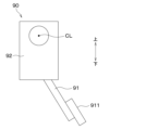
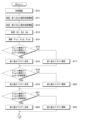
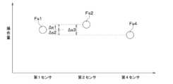
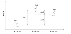
- FIG. 1 is a schematic configuration diagram of a brake system according to the present embodiment. It is an external view of the brake pedal device concerning this embodiment. It is a flowchart which shows the control process which updates the 1st difference flag, the 2nd difference flag, and the 3rd difference flag which the 1st ECU of this embodiment performs. It is a flowchart which shows the majority decision process which the 1st ECU of this embodiment performs. It is a figure which shows an example of the operation amount detected by each sensor when a 1st sensor, a 2nd sensor, and a 4th sensor are in a normal state. It is a figure which shows an example of the operation amount detected by each sensor when a 1st sensor is in an abnormal state.
- the brake system 1 of the present disclosure is a brake-by-wire system that controls the brakes of a vehicle based on the amount of operation of a brake pedal 91 shown in FIG. 2.
- the brake system 1 includes a brake circuit 10 that brakes a vehicle, and wheel cylinders W1 to W4 whose operation is controlled by the brake circuit 10.
- the brake system 1 includes a brake pedal device 90 having a brake pedal 91, a first sensor 21 to a fourth sensor 24 that detect the amount of operation of the brake pedal 91, and a brake circuit. and an electronic control device 30 for driving and controlling 10.
- the brake system 1 includes a power supply section 40 that supplies power to the brake circuit 10 and the electronic control device 30.
- the first sensor 21 to the fourth sensor 24 are provided in the brake pedal device 90.
- the electronic control unit 30 will also be referred to as ECU 30.
- ECU is an abbreviation for Electronic Control Unit. Note that the ECU is sometimes called a BCU (Brake Control Unit).
- the wheel cylinders W1 to W4 are arranged at each wheel of the vehicle. Furthermore, brake pads (not shown) are attached to each of the wheel cylinders W1 to W4.
- the brake circuit 10 can employ various mechanisms. For example, the brake circuit 10 of this embodiment generates a braking force that decelerates the vehicle by generating brake fluid pressure in the wheel cylinders W1 to W4. Note that the brake circuit 10 may employ an electric brake that brakes each wheel by driving an electric motor and pressing a brake pad against a disc brake rotor. The brake circuit 10 is also capable of performing normal control, ABS control, VSC control, etc. in response to control signals from the ECU 30. ABS stands for Anti-lock Braking System. VSC stands for Vehicle Stability Control.
- the brake circuit 10 has a first brake circuit 11 and a second brake circuit 12 that are configured independently of each other.
- the first brake circuit 11 generates brake fluid pressure in a left front wheel cylinder W1 disposed on the left front wheel and a right front wheel cylinder W2 disposed on the right front wheel.
- the second brake circuit 12 generates brake fluid pressure in a left rear wheel cylinder W3 disposed on the left rear wheel and a right rear wheel cylinder W4 disposed on the right rear wheel.
- the first brake circuit 11 and the second brake circuit 12 are supplied with driving power from the power supply section 40. Further, each of the first brake circuit 11 and the second brake circuit 12 is connected to the ECU 30 and controlled by a control signal transmitted from the ECU 30.
- the power supply section 40 has a first power supply section 41 and a second power supply section 42 that are configured independently from each other.
- the first power supply section 41 is connected to the first brake circuit 11 and supplies electric power to the first brake circuit 11.
- the second power supply unit 42 is connected to the second brake circuit 12 and supplies power to the second brake circuit 12.
- the brake system 1 of the present embodiment has different configurations for the power supply source to the first brake circuit 11 and the power supply source to the second brake circuit 12, thereby increasing the power supply source to the brake circuit 10. It is made redundant.
- the ECU 30 is composed of a processor that performs control processing and arithmetic processing, a microcomputer including a storage section such as ROM and RAM that stores programs, data, etc., and its peripheral circuits.
- the storage unit is composed of a non-transitional tangible storage medium.
- the ECU 30 includes a first ECU 31 and a second ECU 32. The first ECU 31 and the second ECU 32 control the operation of the brake circuit 10 by performing various control processes and arithmetic processes based on programs stored in the storage section.
- the first ECU 31 includes three first ECU receivers 311 that receive detection signals transmitted from each of the first sensor 21, second sensor 22, and fourth sensor 24, and a detection signal that each of the three first ECU receivers 311 receives. It has a first ECU processing section 312 that processes. Further, the first ECU 31 includes a first ECU switch 313 that turns on and off the connection between the first ECU 31 and the brake circuit 10. In the first ECU 31, three first ECU receiving sections 311 are provided independently from each other, and the first sensor 21, the second sensor 22, and the fourth sensor 24 are directly connected to the three first ECU receiving sections 311. . Further, the first ECU 31 is connected to the first brake circuit 11 and the second brake circuit 12 via a first ECU switch 313. The first ECU 31 is connected to a first power supply section 41 and is supplied with driving power from the first power supply section 41 . In this embodiment, the first ECU 31 functions as a first electronic control device.
- the second ECU 32 includes two second ECU receiving sections 321 that receive detection signals transmitted from the third sensor 23 and the fourth sensor 24, and a second ECU processing section that processes the detection signals received by the two second ECU receiving sections 321. It has 322. Furthermore, the second ECU 32 includes a second ECU switch 323 that turns on and off the connection between the second ECU 32 and the brake circuit 10. The second ECU 32 is provided with two second ECU receiving sections 321 independently of each other, and the third sensor 23 and the fourth sensor 24 are directly connected to the two second ECU receiving sections 321. Further, the second ECU 32 is connected to the first brake circuit 11 and the second brake circuit 12 via a second ECU switch 323.
- the second ECU 32 is connected to a second power supply section 42 and is supplied with driving power from the second power supply section 42 . In this way, driving power is supplied to the first ECU 31 and the second ECU 32 from mutually different power supplies 41 and 42.
- the second ECU 32 functions as a second electronic control device.
- first ECU 31 and the second ECU 32 are configured to be able to communicate with each other.
- the first ECU 31 is configured to be able to transmit the processing contents of the first ECU processing section 312 to the second ECU 32, and to be able to receive the processing contents of the second ECU processing section 322 in the second ECU 32.
- the second ECU 32 is configured to be able to transmit the processing contents of the second ECU processing section 322 to the first ECU 31 and to be able to receive the processing contents of the first ECU processing section 312 in the first ECU 31 .
- a pendant type brake pedal device 90 is shown as an example of the brake pedal device 90.
- a pedal 911 of the brake pedals 91 which is operated by the driver, is arranged below the pivot axis CL in the vertical direction when mounted on a vehicle. Note that the arrows shown in FIG. 2 indicate the vertical direction when the brake pedal device 90 is mounted on a vehicle.
- the brake pedal device 90 includes a brake pedal 91, a housing 92, and the like.
- the housing 92 is fixed to the dash panel with bolts (not shown) or the like.
- the brake pedal 91 is formed into a plate shape and is arranged diagonally with respect to the floor of the vehicle. Specifically, the brake pedal 91 is arranged diagonally so that its upper end is located at the front of the vehicle and its lower end is located at the rear of the vehicle.
- a pedal 911 that is depressed by the driver is provided at a lower portion of the brake pedal 91.
- the brake pedal 91 is fixed to a rotating shaft (not shown) provided inside the housing 92. Therefore, the brake pedal 91 is provided so as to be able to swing around a predetermined axis CL of a rotating shaft provided within the housing 92. Note that in this specification, rocking refers to rotational movement in the forward and reverse directions around a predetermined axis CL within a predetermined angular range.
- a reaction force generating mechanism that generates a reaction force against the pedal force applied by the driver to the brake pedal 91.
- the first sensor 21 to the fourth sensor 24 shown in FIG. 1 are provided in a brake pedal device 90, detect the amount of operation of the brake pedal 91 depressed by the driver, and output a detection signal according to the detected amount of operation. It is generated and output to the ECU 30.
- the first sensor 21 has a first sensor transmitter 211 that transmits a sensor output signal generated within its own sensor.
- the first sensor transmitter 211 is connected to the first ECU receiver 311.
- the first sensor 21 transmits the generated detection signal from the first sensor transmitter 211 to the first ECU receiver 311.
- the second sensor 22 has a second sensor transmitter 221 that transmits a sensor output signal generated within its own sensor.
- the second sensor transmitter 221 is connected to the first ECU receiver 311.
- the second sensor 22 transmits the generated detection signal from the second sensor transmitter 221 to the first ECU receiver 311.
- the third sensor 23 has a third sensor transmitter 231 that transmits a sensor output signal generated within its own sensor.
- the third sensor transmitter 231 is connected to the second ECU receiver 321.
- the third sensor 23 transmits the generated detection signal from the third sensor transmitter 231 to the second ECU receiver 321.
- the fourth sensor 24 has two fourth sensor transmitters 241 that transmit sensor output signals generated within its own sensor.
- One of the two fourth sensor transmitters 241 is connected to the first ECU receiver 311, and the other is connected to the second ECU receiver 321.
- the fourth sensor 24 divides one detection signal generated within its own sensor into two by duplicating it with an integrated circuit within the sensor, thereby generating two detection signals. These two detection signals are the same signal. Then, the fourth sensor 24 transmits one of the two generated detection signals from the fourth sensor transmitter 241 to the first ECU receiver 311. Further, the fourth sensor 24 transmits the other of the two generated detection signals from the other fourth sensor transmitter 241 to the second ECU receiver 321.
- the first sensor 21 to the fourth sensor 24 may be sensors that detect different physical quantities, as long as they are capable of detecting unique and comparable physical quantities.
- the first sensor 21 to the fourth sensor 24 use three types of physical quantities (for example, pedal swing angle, pedal stroke amount, and pedal pressure) as pedal operation amounts.
- Each sensor uses a different detection method.
- a sensor for detecting the pedal swing angle for example, a magnetic sensor using a Hall element or a magnetic resistance element is employed.
- an inductive sensor is employed as the sensor that detects the pedal stroke amount.
- a pressure sensor is employed as a sensor that detects the pressure when the brake pedal 91 is depressed.
- the first sensor 21 when the first sensor 21 is composed of a magnetic sensor, it is arranged inside the housing 92 .
- the second sensor 22 is an inductive sensor, it is placed outside the housing 92.
- the fourth sensor 24 when the fourth sensor 24 is composed of a pressure sensor, it is arranged inside the pedal 911.
- the first sensor 21, second sensor 22, and fourth sensor 24 connected to the first ECU 31 are configured by combining three sensors that detect using different detection methods.
- the first sensor 21, second sensor 22, and fourth sensor 24 connected to the first ECU 31 include at least two sensors that detect using different detection methods.
- the third sensor 23 and the fourth sensor 24 connected to the second ECU 32 are configured by combining two sensors that detect using different detection methods.
- the third sensor 23 may be composed of the same magnetic sensor as the first sensor 21, and in this case, it is arranged inside the housing 92.
- first to fourth sensors 21 to 24 are not limited to those described above, and various types such as photoelectric sensors and strain sensors may be employed. Further, the names of the first sensor 21 to the fourth sensor 24 do not limit the mounting position or type of the brake pedal device 90. The names of the first ECU 31 and the second ECU 32 do not limit the mounting positions or the like.
- analog communication As a communication method between the first sensor 21 to fourth sensor 24 and the first ECU 31 and second ECU 32, analog communication, digital communication, optical communication, etc. can be adopted.
- digital communication examples include SPI, I2C, UART, and SENT.
- SPI is an abbreviation for Serial Peripheral Interface.
- I2C is an abbreviation for Inter-Integrated Circuit.
- UART is an abbreviation for Universal Asynchronous Receiver/Transmitter.
- SENT is an abbreviation for Single Edge Nibble Transmission.
- first sensor 21 and the second sensor 22 operate by being supplied with power from the first ECU 31. Further, the third sensor 23 and the fourth sensor 24 are operated by being supplied with power from the second ECU 32. Even if the first ECU 31 fails, the fourth sensor 24 can continue to operate because it is supplied with power from the second ECU 32; however, if the second ECU 32 fails and the power supply from the second ECU 32 stops. , it becomes impossible to continue operation.
- a voltage of 5V is applied to the first sensor 21 and the second sensor 22 from the first ECU 31. Further, a voltage of 5V is applied to the third sensor 23 and the fourth sensor 24 from the second ECU 32.
- each of the first to fourth sensors 21 to 24 detects the amount of operation of the brake pedal 91, generates a detection signal according to the detected amount of operation, and outputs a detection signal corresponding to the detected amount of operation. It outputs to the connected first ECU 31 and second ECU 32.
- the first sensor 21 outputs a detection signal corresponding to the detected operation amount of the brake pedal 91 to the first ECU receiving section 311 of the first ECU 31.
- the second sensor 22 outputs a detection signal corresponding to the detected operation amount of the brake pedal 91 to the first ECU receiving section 311 of the first ECU 31 .
- the third sensor 23 outputs a detection signal corresponding to the detected operation amount of the brake pedal 91 to the second ECU receiving section 321 of the second ECU 32 .
- the fourth sensor 24 outputs a detection signal corresponding to the detected operation amount of the brake pedal 91 to the first ECU receiving section 311 of the first ECU 31 and the second ECU receiving section 321 of the second ECU 32.
- the first ECU 31 and the second ECU 32 When the first ECU 31 and the second ECU 32 receive a detection signal corresponding to the operation amount of the brake pedal 91 from the first sensor 21 to the fourth sensor 24, the first ECU 31 and the second ECU 32 calculate a target deceleration, which will be described later, based on the input detection signal. In the determination process, a target deceleration of the vehicle is calculated. The first ECU 31 and the second ECU 32 control the first brake circuit 11 and the second brake circuit 12 by outputting the calculated target deceleration information to the first brake circuit 11 and the second brake circuit 12.
- the first brake circuit 11 When information on the target deceleration is input, the first brake circuit 11 generates brake fluid pressure in the left front wheel cylinder W1 and the right front wheel cylinder W2 in accordance with the target deceleration. Further, when information on the target deceleration is input, the second brake circuit 12 generates brake fluid pressure in the left rear wheel cylinder W3 and the right rear wheel cylinder W4 in accordance with the target deceleration. Thereby, the brake system 1 generates braking force for decelerating the vehicle at the left front wheel, right front wheel, left rear wheel, and right rear wheel.
- the first ECU 31 and the second ECU 32 start control processing, for example, when a running switch such as an ignition switch or a power switch of the vehicle is turned on.
- the first ECU 31 receives the detection signals transmitted by the first sensor 21, the second sensor 22, and the fourth sensor 24, the first ECU 31 executes the control process shown in FIGS. 3 and 4 at a predetermined control cycle in the target deceleration determination process. Repeat each time. Further, upon receiving the detection signals transmitted by the second sensor 22 and the fourth sensor 24, the second ECU 32 repeats the control process shown in FIGS. 10 and 11 described later at every predetermined control cycle in the target deceleration determination process. Execute.
- the detection signal transmitted by the first sensor 21 is the first signal S1
- the detection signal transmitted by the second sensor 22 is the second signal S2
- the detection signal transmitted by the third sensor 23 is the third signal S3
- the fourth sensor The detection signal transmitted by 24 is also referred to as a fourth signal S4.
- the brake system 1 of this embodiment redundancy as a system is ensured by the configuration in which the ECU 30 includes the first ECU 31 and the second ECU 32. That is, the brake system 1 of this embodiment is configured such that the first ECU 31 can calculate the target deceleration, and the second ECU 32 can calculate the target deceleration. Therefore, for example, if the target deceleration cannot be calculated due to a failure of the first ECU 31, the second ECU 32 can calculate the target deceleration. However, among the first ECU 31 and the second ECU 32, the first ECU 31, which has a large number of connected sensors, is set as a main control device, and the second ECU 32 is set as a standby control device. Therefore, when both the first ECU 31 and the second ECU 32 can normally calculate the target deceleration, the first ECU 31 holds control initiative of the brake system 1, and the first ECU 31 calculates the target deceleration.
- the first ECU 31 determines whether its own operating state is a normal state or an abnormal state.
- the normal state is a state in which the first ECU 31 can normally receive the first signal S1, the second signal S2, and the fourth signal S4, and can normally supply power to the first sensor 21 and the second sensor 22. It is.
- the normal state means that when the first signal S1, the second signal S2, and the fourth signal S4 are received, the first ECU processing unit 312 It is in a state where normal processing operations are possible.
- an abnormal state means that it is impossible to receive the first signal S1, the second signal S2, and the fourth signal S4, it is impossible to supply power to the first sensor 21 and the second sensor 22, and the first ECU processing unit 312 is in a state where one or more of these are in a state in which it cannot operate normally.
- the first ECU 31 outputs information about its own determined operating state to the second ECU 32.
- the first ECU 31 acquires from the second ECU 32 information on the operating state of the second ECU 32, which is determined in the control process of the second ECU 32, which will be described later.
- step S13 the first ECU 31 receives the first signal S1 transmitted from the first sensor 21, the second signal S2 transmitted from the second sensor 22, and the signal S2 transmitted from the fourth sensor 24.
- the fourth signal S4 to be transmitted is obtained.
- the first ECU processing unit 312 When the first ECU 31 acquires the first signal S1, the second signal S2, and the fourth signal S4, in step S14, the first ECU processing unit 312 performs a , the operation amount of the brake pedal 91 is calculated. Specifically, upon acquiring the first signal S1, the first ECU processing unit 312 calculates the operation amount of the brake pedal 91 detected by the first sensor 21 based on the first signal S1 and a predetermined control map. do. Further, upon acquiring the second signal S2, the first ECU processing unit 312 calculates the operation amount of the brake pedal 91 detected by the second sensor 22 based on the second signal S2 and a predetermined control map. Furthermore, upon acquiring the fourth signal S4, the first ECU processing unit 312 calculates the operation amount of the brake pedal 91 detected by the fourth sensor 24 based on the fourth signal S4 and a predetermined control map.
- the operation amount of the brake pedal 91 calculated based on the first signal S1 is also referred to as the first operation amount Fs1
- the operation amount of the brake pedal 91 calculated based on the second signal S2 is also referred to as the second operation amount Fs2.
- the operation amount of the brake pedal 91 calculated based on the fourth signal S4 is also referred to as the fourth operation amount Fs4.
- the operation amount of the brake pedal 91 calculated by the second ECU 32 based on the third signal S3 is also referred to as the third operation amount Fs3.
- the first ECU processing unit 312 selects the first sensor 21 connected to the first ECU 31, the second sensor It is determined whether or not there is a failure in the sensor 22 and the fourth sensor 24. That is, the first ECU processing unit 312 determines whether all sensors among the first sensor 21, second sensor 22, and fourth sensor 24 connected to the first ECU 31 are in a normal state, and one sensor is in an abnormal state. Detect whether there is one or more. Further, the first ECU processing unit 312 detects one sensor that is in an abnormal state when there is one sensor that is in an abnormal state, and detects one sensor that is in an abnormal state when there is a plurality of sensors that are in an abnormal state. Detect the sensor.
- the first ECU processing unit 312 determines whether the first manipulated variable Fs1 and the second manipulated variable Fs2 are normal or abnormal, and also determines whether the first manipulated variable Fs1 and the second manipulated variable Fs2 are It is determined whether the first difference value ⁇ s1, which is the difference value, is smaller than an allowable error.
- the first manipulated variable Fs1 and the second manipulated variable Fs2 are determined to be normal, for example, when they are greater than or equal to the minimum value of the manipulated variables assumed in advance and less than or equal to the maximum value of the assumed amounts assumed in advance.
- the first manipulated variable Fs1 and the second manipulated variable Fs2 are determined to be abnormal if, for example, they are smaller than the minimum value of the manipulated variables assumed in advance or larger than the maximum value of the expected amounts assumed in advance. be done. Note that it is similarly determined whether a third manipulated variable Fs3 and a fourth manipulated variable Fs4, which will be described later, are normal or abnormal.
- the first difference value ⁇ s1 is a value obtained by subtracting the second manipulated variable Fs2 from the first manipulated variable Fs1, and is calculated as an absolute value.
- the allowable error of the first difference value ⁇ s1 is determined, for example, within a range in which the detection error of the first sensor 21 itself and the detection error of the second sensor 22 itself overlap.
- a second difference value ⁇ s2 which is the difference value between the first manipulated variable Fs1 and the fourth manipulated variable Fs4, and a third difference value ⁇ s3, which is the difference value between the second manipulated variable Fs2 and the fourth manipulated variable Fs4, which will be described later, is also Obtained by a similar calculation method.
- the fourth difference value ⁇ s4, which is the difference value between the third manipulated variable Fs3 and the fourth manipulated variable Fs4, is also obtained by the same calculation method.
- the allowable error of the second difference value ⁇ s2 is determined, for example, within a range in which the detection error of the first sensor 21 itself and the detection error of the fourth sensor 24 itself overlap.
- the allowable error of the third difference value ⁇ s3 is determined by the detection error of each of the second sensor 22 and the fourth sensor 24, for example.
- the allowable error of the fourth difference value ⁇ s4 is determined, for example, within a range in which the detection error of the third sensor 23 itself and the detection error of the fourth sensor 24 itself overlap.
- the first ECU processing unit 312 sets the first difference value ⁇ s1 to The first difference flag indicating whether the is normal or abnormal is set to normal.
- the first ECU process The unit 312 makes the first difference flag abnormal.
- step S18 the first ECU processing unit 312 determines whether the first manipulated variable Fs1 and the fourth manipulated variable Fs4 are normal or abnormal, and determines whether the second difference value ⁇ s2 is smaller than the allowable error. do.
- the first ECU processing unit 312 sets the second difference value ⁇ s2 to The second difference flag indicating whether the is normal or abnormal is set to normal.
- the first ECU processing unit 312 makes the second difference flag abnormal.
- step S21 the first ECU processing unit 312 determines whether the second manipulated variable Fs2 and the fourth manipulated variable Fs4 are normal or abnormal, and determines whether the third difference value ⁇ s3 is smaller than the allowable error. do.
- the first ECU processing unit 312 makes the third difference flag abnormal.
- the respective tolerances for determining whether or not the first difference value ⁇ s1, the second difference value ⁇ s2, and the third difference value ⁇ s3 are smaller than the tolerance may be of different sizes or may be the same. It may be the size.
- the tolerance for determining whether the first difference value ⁇ s1 is smaller than the tolerance and the tolerance for determining whether the second difference value ⁇ s2 is smaller than the tolerance may have different sizes. There may be one or the same size.
- the tolerance for determining whether the second difference value ⁇ s2 is smaller than the tolerance error and the tolerance error for determining whether the third difference value ⁇ s3 is smaller than the tolerance error are different in size from each other. There may be one or the same size.
- the first ECU processing unit 312 After updating the states of the first difference flag, second difference flag, and third difference flag in steps S10 to S23, the first ECU processing unit 312 performs majority decision processing.
- the majority decision process is a process for determining whether each of the first manipulated variable Fs1, second manipulated variable Fs2, and fourth manipulated variable Fs4 can be used to calculate the target deceleration. In other words, the majority decision process determines whether it can be confirmed that there is a sensor in a normal state among the first sensor 21, second sensor 22, and fourth sensor 24 connected to the first ECU 31. It is processing.
- step S30 it is determined whether the first difference flag, the second difference flag, and the third difference flag are normal.
- the first manipulated variable Fs1, the second manipulated variable Fs2, and the fourth manipulated variable Fs4 are relatively close values, and all of the first difference flag, second difference flag, and third difference flag are An example of a normal case is shown in FIG.
- the horizontal axis in FIG. 5 indicates the first sensor 21, the second sensor 22, and the fourth sensor 24, respectively.
- the vertical axis indicates the operation amount of the brake pedal 91 calculated based on the detection signals transmitted from each of the first sensor 21, the second sensor 22, and the fourth sensor 24. Note that what the vertical and horizontal axes indicate is the same in FIGS. 6 to 8, which will be referred to in the explanation below.
- the first sensor 21, the second sensor 22, and the fourth sensor 24 connected to the first ECU 31 are a combination of three sensors that detect the operation amount of the brake pedal 91 using different detection methods. It is configured. Therefore, the possibility that the first sensor 21, the second sensor 22, and the fourth sensor 24, which have different detection methods from each other, fail at the same time due to external factors is relatively low.
- the values of the first manipulated variable Fs1, the second manipulated variable Fs2, and the fourth manipulated variable Fs4 are relatively close values or substantially similar values, and the first difference flag, the second difference flag, and the third difference flag Assume that everything is normal.
- the first sensor 21, second sensor 22, and fourth sensor 24 is not malfunctioning. That is, there is a high possibility that each of the first sensor 21, the second sensor 22, and the fourth sensor 24 is in a normal state.
- the first operation amount Fs1, the second operation amount Fs2, and the third operation amount Fs3 are calculated based on the detection signals transmitted from the first sensor 21, the second sensor 22, and the fourth sensor 24 that are in the normal state. Each of these values is likely to be normal.
- step S30 if the first difference flag, the second difference flag, and the third difference flag are all normal, the first ECU processing unit 312 determines that the first sensor 21 and the second sensor connected to the first ECU 31 22 and the fourth sensor 24 are all determined to be normal. That is, the first ECU processing unit 312 determines that there is a sensor in a normal state among the first sensor 21, second sensor 22, and fourth sensor 24 connected to the first ECU 31, and also specifies the sensor in a normal state. do. Then, in step S31, the first ECU processing unit 312 sets the majority flag indicating the majority decision processing result to normal indicating that all the connected sensors are normal, and sends information that the majority flag is normal to the second ECU 32. Send.
- step S32 the first ECU processing unit 312 issues a brake control command based on the detection signal transmitted from the sensor determined to be in a normal state among the first sensor 21, second sensor 22, and fourth sensor 24.
- the operation amount of the brake pedal 91 that becomes the value is determined.
- the brake pedal 91 is Determine the amount of operation. For example, the priority in this embodiment is given to the first sensor 21, second sensor 22, and fourth sensor 24, which detect the operation amount of the brake pedal 91 using different detection methods, in the order in which the detection accuracy is assumed to be highest. , a first sensor 21, a second sensor 22, and a fourth sensor 24.
- step S32 the first ECU processing unit 312 calculates the first operation amount of the brake pedal 91 based on the operation amount detected by the first sensor 21.
- the manipulated variable is determined to be Fs1.
- the first ECU processing unit 312 calculates the target deceleration of the vehicle based on the determined first operation amount Fs1 of the brake pedal 91 and a predetermined control map.
- the priority for determining the operation amount of the brake pedal 91 is not limited to this order, and for example, the priority for determining the operation amount of the brake pedal 91 is set in an order different from the order of the first sensor 21, the second sensor 22, and the fourth sensor 24.
- the four sensors 24 and the first sensor 21 may be determined in this order.
- the priority for determining the operation amount of the brake pedal 91 may be the order of the fourth sensor 24, the first sensor 21, and the second sensor 22, the order of the first sensor 21, the fourth sensor 24, and the second sensor 22, etc. may be set.
- the priority for determining the amount of operation of the brake pedal 91 is a different order from the order in which the detection accuracy is assumed to be high, and for example, the order in which the failure frequency is assumed to be low, or the order in which the failure frequency is assumed to be low, or They may also be set in order of difficulty in receiving them.
- the operation amount of the brake pedal 91 may be determined using a method different from the sensor priority.
- the operation amount of the brake pedal 91 may be determined to be the maximum value or the minimum value among the operation amounts calculated based on the detection signals transmitted from each sensor determined to be in a normal state. It's okay.
- the operation amount of the brake pedal 91 is the operation amount calculated from the detection signals transmitted from all the sensors. Among them, a value different from the maximum value and the minimum value may be determined.
- the operation amount of the brake pedal 91 may be determined based on a predetermined function and a detection signal transmitted from each sensor determined to be in a normal state.
- the operation amount of the brake pedal 91 may be determined to be the average value of the operation amounts calculated based on the detection signals transmitted from each sensor determined to be in a normal state.
- the operation amount of the brake pedal 91 is detected by a sensor different from the sensor that detects the maximum and minimum values among the operation amounts calculated based on the detection signals transmitted from each sensor determined to be in a normal state. It may be determined based on the amount of operation to be performed.
- the first ECU 31 and the second ECU 32 of this embodiment the first ECU 31 with a large number of connected sensors is set as a main control device, and the second ECU 32 is set as a standby control device. Therefore, if the target deceleration of the vehicle can be calculated on the first ECU 31 side, the target deceleration of the vehicle is set to the target deceleration calculated by the first ECU 31. Then, the first ECU 31 is connected to the first brake circuit 11 and the second brake circuit 12 by the first ECU switch 313 . Further, the second ECU 32 is disconnected from the first brake circuit 11 and the second brake circuit 12 by the second ECU switch 323 . The first ECU 31 then controls the first brake circuit 11 and the second brake circuit 12 by outputting the information on the target deceleration calculated in step S32 to the first brake circuit 11 and the second brake circuit 12.
- step S30 If it is not determined in step S30 that all of the first difference flag, second difference flag, and third difference flag are normal, the first ECU processing unit 312 executes the process of step S33.
- step S33 the first ECU processing unit 312 determines whether the first difference flag is abnormal, the second difference flag is abnormal, and the third difference flag is normal.
- the second manipulated variable Fs2 and the fourth manipulated variable Fs4 are relatively close to each other and the third difference value ⁇ s3 is smaller than the allowable error is shown in FIG.
- the value of the first manipulated variable Fs1 deviates relatively largely from the respective values of the second manipulated variable Fs2 and the fourth manipulated variable Fs4, and the first difference value ⁇ s1 and the second difference value ⁇ s2 Each is above the allowable error. In such a case, the first difference flag and the second difference flag become abnormal, and the third difference flag becomes normal.
- any one of the first sensor 21, the second sensor 22, and the fourth sensor 24 is malfunctioning.
- the two sensors are not malfunctioning. That is, two of the first sensor 21, second sensor 22, and fourth sensor 24 are in a normal state, and the brake pedal is calculated based on detection signals transmitted from these two sensors in a normal state. It is highly likely that each of the 91 manipulated variables is a normal value.
- the remaining one sensor is in an abnormal state, and the operation amount of the brake pedal 91 calculated based on the detection signal transmitted from the remaining one sensor in this abnormal state may be an abnormal value. Highly sexual.
- the first ECU processing unit 312 controls the first sensor 21 connected to the first ECU 31, the second difference flag, and the second difference flag. It is determined that one of the sensor 22 and the fourth sensor 24 is in an abnormal state. Specifically, the first ECU processing unit 312 determines that the sensor that has detected the common operation amount used to calculate two abnormal difference flags is in an abnormal state. Then, the sensors that are not determined to be in an abnormal state are determined to be in a normal state.
- the first ECU processing unit 312 determines that there is a sensor in a normal state among the first sensor 21, second sensor 22, and fourth sensor 24 connected to the first ECU 31, and also specifies the sensor in a normal state. do. For example, in the example shown in FIG. 6, the first ECU processing unit 312 detects that the first sensor 21 that has detected the first manipulated variable Fs1 used to calculate the abnormal first difference flag and second difference flag is in an abnormal state. It is determined that Further, the first ECU processing unit 312 determines that the second sensor 22 and the fourth sensor 24 are in a normal state.
- step S34 the majority flag is set to 1st sensor abnormality indicating that the first sensor 21 is in an abnormal state, and information that the majority flag is 1st sensor abnormality is transmitted to the second ECU 32.
- step S35 the first ECU processing unit 312 detects the detection transmitted from the second sensor 22 and the fourth sensor 24 that are determined to be in a normal state among the first sensor 21, the second sensor 22, and the fourth sensor 24. Based on the signal, the amount of operation of the brake pedal 91 is determined. Specifically, the first ECU processing unit 312 determines the operation amount of the brake pedal 91 to be the second operation amount Fs2 based on a predetermined priority.
- the first ECU processing unit 312 calculates the target deceleration of the vehicle based on the second operation amount Fs2, which is the determined operation amount of the brake pedal 91, and a predetermined control map. Then, the first ECU 31 is connected to the first brake circuit 11 and the second brake circuit 12 by the first ECU switch 313 . Further, the second ECU 32 is disconnected from the first brake circuit 11 and the second brake circuit 12 by the second ECU switch 323 . The first ECU 31 then controls the first brake circuit 11 and the second brake circuit 12 by outputting information about the calculated target deceleration to the first brake circuit 11 and the second brake circuit 12.
- step S33 determines whether the first difference flag is abnormal, the second difference flag is abnormal, and the third difference flag is normal. If it is not determined in step S33 that the first difference flag is abnormal, the second difference flag is abnormal, and the third difference flag is normal, the first ECU processing unit 312 executes the process of step S36. .
- step S36 the first ECU processing unit 312 determines whether the first difference flag is abnormal, the third difference flag is abnormal, and the second difference flag is normal.
- the first ECU processing unit 312 uses the first difference flag and the third difference flag to calculate the first difference flag and the third difference flag. It is determined that the second sensor 22 that has detected the second operation amount Fs2 is in an abnormal state. Further, the first ECU processing unit 312 determines that the first sensor 21 and the fourth sensor 24 are in a normal state.
- the first ECU processing unit 312 determines that there is a sensor in a normal state among the first sensor 21, second sensor 22, and fourth sensor 24 connected to the first ECU 31, and also specifies the sensor in a normal state. do.
- step S37 the majority flag indicating majority decision processing is set to second sensor abnormality indicating that the second sensor 22 is in an abnormal state, and information that the majority flag indicates second sensor abnormality is transmitted to the second ECU 32.
- step S38 the first ECU processing unit 312 detects the detection transmitted from the first sensor 21 and the fourth sensor 24 that are determined to be in a normal state among the first sensor 21, the second sensor 22, and the fourth sensor 24. Based on the signal, the amount of operation of the brake pedal 91 is determined. Specifically, the first ECU processing unit 312 determines the operation amount of the brake pedal 91 to be the first operation amount Fs1 based on a predetermined priority.
- the first ECU processing unit 312 calculates the target deceleration of the vehicle based on the determined first operation amount Fs1 of the brake pedal 91 and a predetermined control map. Then, the first ECU 31 is connected to the first brake circuit 11 and the second brake circuit 12 by the first ECU switch 313 . Further, the second ECU 32 is disconnected from the first brake circuit 11 and the second brake circuit 12 by the second ECU switch 323 . The first ECU 31 then controls the first brake circuit 11 and the second brake circuit 12 by outputting information about the calculated target deceleration to the first brake circuit 11 and the second brake circuit 12.
- step S36 determines whether the first difference flag is abnormal, the third difference flag is abnormal, and the second difference flag is normal. If it is not determined in step S36 that the first difference flag is abnormal, the third difference flag is abnormal, and the second difference flag is normal, the first ECU processing unit 312 executes the process of step S39. .
- step S39 the first ECU processing unit 312 determines whether the second difference flag is abnormal, the third difference flag is abnormal, and the first difference flag is normal.
- the first ECU processing unit 312 uses the second difference flag and the third difference flag to calculate the second difference flag and the third difference flag. It is determined that the fourth sensor 24 that has detected the fourth manipulated variable Fs4 is in an abnormal state. Further, the first ECU processing unit 312 determines that the first sensor 21 and the second sensor 22 are in a normal state.
- the first ECU processing unit 312 determines that there is a sensor in a normal state among the first sensor 21, second sensor 22, and fourth sensor 24 connected to the first ECU 31, and also specifies the sensor in a normal state. do.
- step S40 the majority flag is set to 4th sensor abnormality indicating that the fourth sensor 24 is in an abnormal state, and information that the majority flag is 4th sensor abnormality is transmitted to the second ECU 32.
- step S41 the first ECU processing unit 312 detects the detection transmitted from the first sensor 21 and the second sensor 22 that are determined to be in a normal state among the first sensor 21, the second sensor 22, and the fourth sensor 24. Based on the signal, the amount of operation of the brake pedal 91 is determined. Specifically, the first ECU processing unit 312 determines the operation amount of the brake pedal 91 to be the first operation amount Fs1 based on a predetermined priority.
- the first ECU processing unit 312 calculates the target deceleration of the vehicle based on the determined first operation amount Fs1 of the brake pedal 91 and a predetermined control map. Then, the first ECU 31 is connected to the first brake circuit 11 and the second brake circuit 12 by the first ECU switch 313 . Further, the second ECU 32 is disconnected from the first brake circuit 11 and the second brake circuit 12 by the second ECU switch 323 . The first ECU 31 then controls the first brake circuit 11 and the second brake circuit 12 by outputting information about the calculated target deceleration to the first brake circuit 11 and the second brake circuit 12.
- step S42 executes the process of step S42.
- the process of step S42 is executed when all three difference flags among the first difference flag, second difference flag, and third difference flag are abnormal, or when any two difference flags are abnormal.
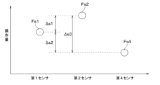
- FIG. 7 shows an example of a case where the error is greater than or equal to the allowable error. In such a case, the first difference flag, the second difference flag, and the third difference flag all become abnormal.
- the brake pedal 91 is calculated based on the detection signals transmitted from these three abnormal sensors. There is a high possibility that the manipulated variable is an abnormal value.
- the brake pedal 91 is calculated based on the detection signal transmitted from one sensor that is in a normal state.
- the manipulated variable is likely to be a normal value.
- the respective values of the first manipulated variable Fs1, second manipulated variable Fs2, and fourth manipulated variable Fs4 deviate relatively greatly from each other, the values of the first manipulated variable Fs1, the second manipulated variable Fs2, and the fourth manipulated variable It is not possible to identify a sensor that is in a normal state only by comparing the manipulated variable Fs4.
- the first ECU processing unit 312 controls the first sensor 21, the second sensor 22, and the fourth sensor connected to the first ECU 31. It is determined that a plurality of sensors among the sensors 24 are in an abnormal state. That is, the first ECU processing unit 312 does not determine that there is a sensor in a normal state among the first sensor 21, second sensor 22, and fourth sensor 24 connected to the first ECU 31, but identifies the sensor in a normal state. do not.
- step S42 the first ECU processing unit 312 sets the majority decision flag to majority decision failure, which indicates that a sensor in a normal state cannot be identified, and transmits information that the majority decision flag indicates majority decision failure to the second ECU 32.
- the first ECU processing unit 312 then ends the process without determining the operation amount of the brake pedal 91. That is, the first ECU processing unit 312 does not output information on the target deceleration to the first brake circuit 11 and the second brake circuit 12.
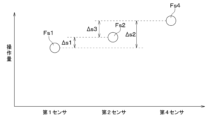
- FIG. 8 shows an example in which the second manipulated variable Fs2 is relatively close to the first manipulated variable Fs1 and the fourth manipulated variable Fs4, and the first difference value ⁇ s1 and the third difference value ⁇ s3 are smaller than the allowable error. Shown below.
- the value of the first manipulated variable Fs1 deviates relatively largely from the value of the fourth manipulated variable Fs4, and the second difference value ⁇ s2 is greater than the allowable error. In such a case, the first difference flag and the third difference flag are normal, and the second difference flag is abnormal.
- the first ECU processing unit 312 controls the first sensor 21, the second sensor 22, and the fourth sensor 24. It is determined that one or more of the sensors is in an abnormal state. That is, the first ECU processing unit 312 does not determine that there is a sensor in a normal state among the first sensor 21, second sensor 22, and fourth sensor 24 connected to the first ECU 31, but identifies the sensor in a normal state. do not.
- step S42 the first ECU processing unit 312 sets the majority decision flag to majority decision failure, and transmits information that the majority decision flag indicates majority decision failure to the second ECU 32.
- the first ECU processing unit 312 then ends the process without determining the operation amount of the brake pedal 91. That is, the first ECU processing unit 312 does not output information on the target deceleration to the first brake circuit 11 and the second brake circuit 12.
- the operation amount of the brake pedal 91 is determined as shown in the table shown in FIG. Basically, in the brake system 1 of this embodiment, if a sensor in a normal state can be identified by the first ECU 31 set on the main side, the sensor with the highest priority among the sensors in a normal state is detected. The amount of operation of the brake pedal 91 is determined based on the signal. That is, if it is not determined that the majority decision has failed in the majority decision processing, the target deceleration can be calculated regardless of whether the second ECU 32 is in a normal state or an abnormal state.
- the first ECU 31 determines that the majority decision has failed and it is not possible to identify the sensor that is in a normal state
- the first ECU 31 cannot determine the operation amount of the brake pedal 91. Therefore, when the second ECU 32 is in a normal state, the operation amount of the brake pedal 91 is determined by the control process executed by the second ECU 32.
- step S50 the second ECU 32 determines whether its own operating state is normal or abnormal.
- the normal state is a state in which the second ECU 32 can normally receive the third signal S3 and the fourth signal S4, and can normally supply power to the third sensor 23 and the fourth sensor 24.
- the normal state is a state in which the second ECU processing unit 322 is able to perform normal processing operations based on the third signal S3 and the fourth signal S4 when receiving the third signal S3 and the fourth signal S4. be.
- an abnormal state means that it is impossible to receive the third signal S3 and the fourth signal S4, it is impossible to supply power to the third sensor 23 and the fourth sensor 24, and the second ECU processing section 322 performs normal processing. This is a state in which one or more of these conditions are incapable of being performed.
- the second ECU 32 outputs information about its own determined operating state to the first ECU 31. Further, in step S52, the second ECU 32 acquires from the first ECU 31 information on the operating state of the first ECU 31 determined in the process of step S11 of the first ECU 31.
- step S53 the second ECU 32 acquires information on the majority flag set in the majority decision process of the first ECU 31.
- the second ECU 32 acquires the third signal S3 transmitted from the third sensor 23 and the fourth signal S4 transmitted from the fourth sensor 24 in step S54.
- the second ECU 32 is in an abnormal state, all processes after step S54 are skipped.
- step S54 when the second ECU 32 acquires the third signal S3 and the fourth signal S4, the second ECU processing unit 322 calculates the operation amount of the brake pedal 91 based on the third signal S3 and the fourth signal S4, respectively. . Specifically, upon acquiring the third signal S3, the second ECU processing unit 322 calculates the third operation amount Fs3 based on the third signal S3 and a predetermined control map. Further, upon acquiring the fourth signal S4, the second ECU processing section 322 calculates the fourth operation amount Fs4 based on the fourth signal S4 and a predetermined control map. The fourth operation amount Fs4 calculated by the second ECU processing section 322 in step S54 is equal to the fourth operation amount Fs4 calculated by the first ECU processing section 312 in step S14.
- step S55 the second ECU processing unit 322 performs sensor abnormality determination processing in the second ECU 32 based on the calculated third operation amount Fs3 and fourth operation amount Fs4.
- the sensor abnormality determination of the second ECU 32 is performed to determine whether both the third sensor 23 and the fourth sensor 24 connected to the second ECU 32 are in a normal state, and whether at least one is in an abnormal state.
- step S55 the second ECU processing unit 322 determines whether the third manipulated variable Fs3 and the fourth manipulated variable Fs4 are normal or abnormal, and determines the difference between the third manipulated variable Fs3 and the fourth manipulated variable Fs4. It is determined whether the fourth difference value ⁇ s4 is smaller than the allowable error.
- the third sensor 23 and the fourth sensor 24 connected to the second ECU 32 are configured by combining two sensors that detect the operation amount of the brake pedal 91 using different detection methods. . Therefore, there is a relatively low possibility that the two third and fourth sensors 23 and 24, which have different detection methods, will fail at the same time due to external factors.
- the third sensor 23 and the fourth manipulated variable Fs4 are relatively close or substantially the same, and the fourth difference value ⁇ s4 is smaller than the allowable error, the third sensor 23 and the fourth It is highly likely that each of the sensors 24 is not malfunctioning. That is, the third sensor 23 and the fourth sensor 24 are each in a normal state, and the two brake pedals 91 are calculated based on the detection signals transmitted from the third sensor 23 and the fourth sensor 24 that are in the normal state. It is highly likely that each of the manipulated variables is a normal value.
- the second ECU processing section 322 controls the third sensor 23 connected to the second ECU 32 and the fourth operation amount Fs4. It is determined that all of the fourth sensors 24 are in a normal state. That is, the second ECU processing unit 322 determines that there is a sensor in a normal state in the third sensor 23 and fourth sensor 24 connected to the second ECU 32, and also specifies the sensor in a normal state.
- the third sensor 23 and the fourth sensor There is a high possibility that at least one of 24 is out of order. That is, at least one of the third sensor 23 and the fourth sensor 24 is in an abnormal state, and the operating amounts of the two brake pedals 91 calculated based on the detection signals transmitted from the third sensor 23 and the fourth sensor 24 are There is a high possibility that at least one of the values is an abnormal value.
- the fourth difference value ⁇ s4 is greater than or equal to the allowable error, there is a possibility that both the third sensor 23 and the fourth sensor 24 are malfunctioning. There is a possibility that both of the operation amounts of the two brake pedals 91 calculated based on the detection signals transmitted from the third sensor 23 and the fourth sensor 24 are abnormal values.
- the second ECU processing section 322 is connected to the second ECU 32, and the third sensor 23 and the fourth It is determined that at least one of the sensors 24 is in an abnormal state. That is, the second ECU processing unit 322 does not determine that there is a sensor in a normal state in the third sensor 23 and fourth sensor 24 connected to the second ECU 32, and does not specify a sensor in a normal state.
- step S56 the second ECU processing unit 322 controls the third sensor 23 and the fourth sensor The fourth difference flag indicating that No. 24 is normal is set to normal.
- the second ECU processing unit 322 then executes the process of step S58.
- step S57 the second ECU processing unit 322 makes the fourth difference flag abnormal. Then, the second ECU processing unit 322 skips the processing of step S58 and step S59.
- the size of the tolerance used when the first ECU 31 executes the majority decision process and the size of the tolerance used when the second ECU 32 executes the sensor abnormality determination process may be different from each other. , may be the same size.
- step S58 the second ECU processing unit 322 determines that the fourth sensor 24 is determined to be in an abnormal state or is likely to be in an abnormal state, based on the information of the majority flag transmitted from the first ECU 31. Determine whether or not.
- the process of step S58 is executed to determine whether the fourth sensor 24 is in a normal state in the majority decision process performed by the first ECU 31 before step S58 is executed.
- the second ECU processing unit 322 determines that the majority flag information transmitted from the first ECU 31 indicates that the fourth sensor is not abnormal and that the majority decision has not failed. If the second ECU processing unit 322 determines that the majority flag information transmitted from the first ECU 31 indicates that the fourth sensor is not abnormal and that the majority decision has not failed, the second ECU processing unit 322 executes the process of step S59. In other words, when it is determined that the majority flag information transmitted from the first ECU 31 is normal, the first sensor is abnormal, or the second sensor is abnormal, the process of step S59 is executed.
- step S59 the second ECU processing unit 322 turns on the normal experience flag indicating that the fourth sensor 24 is determined to be in a normal state in the majority decision process of the first ECU 31 that is executed after the ignition switch of the vehicle is turned on. do.
- the normal experience flag is a flag for determining whether the state of the fourth sensor 24 is normal or abnormal after the ignition switch of the vehicle is turned on.
- the normal experience flag remains on until the ignition switch is turned off. do. In other words, the normal experience flag remains on after the ignition switch of the vehicle is turned on, if it is confirmed by the majority decision process of the first ECU 31 that the state of the fourth sensor 24 is in a normal state. be done.
- step S58 the determination process in step S58 is executed when both the third sensor 23 and the fourth sensor 24 are determined to be in a normal state in the determination process in step S55. Therefore, when the normal experience flag is on, not only the fourth sensor 24 was in a normal state after the vehicle's ignition switch was turned on, but also the third sensor 23 was in a normal state. Show that.
- the normal experience flag is a flag whose initial value is set to OFF when the ignition switch of the vehicle is turned on. Therefore, if either the third sensor 23 or the fourth sensor 24 is in an abnormal state when the ignition switch of the vehicle is turned on, a negative determination is made in step S55, and the normal experience flag is set to the ignition switch. It remains off until it is turned off. Furthermore, if it is not determined that the fourth sensor 24 is in a normal state in the majority decision process of the first ECU 31 executed after the ignition switch of the vehicle is turned on, the normal experience flag remains in the off state until the ignition switch is turned off. is maintained.
- step S60 the second ECU processing unit 322 determines whether the first ECU 31 is in a normal state based on the information on the operating state of the first ECU 31 transmitted from the first ECU 31. Further, in step S61, the second ECU processing unit 322 determines whether the information of the majority flag transmitted from the first ECU 31 indicates that the majority decision has failed.
- the target deceleration of the vehicle is calculated by the first ECU 31.
- the first ECU 31 can receive normal detection signals from at least two of the first sensor 21, second sensor 22, and fourth sensor 24 that are in a normal state. Therefore, the first ECU 31 can calculate the operation amount of the brake pedal 91 based on the detection signal from the sensor in this normal state. Therefore, if a negative determination is not made in step S60 and step S61, the second ECU processing unit 322 ends the process without determining the operation amount of the brake pedal 91. That is, the second ECU processing section 322 does not output information on the target deceleration to the first brake circuit 11 and the second brake circuit 12.
- the target deceleration of the vehicle cannot be calculated by the first ECU 31.
- the first ECU 31 is unable to identify which sensor among the first sensor 21, second sensor 22, and fourth sensor 24 is in a normal state.
- the first ECU 31 cannot calculate the operation amount of the brake pedal 91 based on the detection signals from the first sensor 21, the second sensor 22, and the fourth sensor 24. Therefore, if a negative determination is made in step S60 or step S61, control initiative is transferred from the first ECU 31 to the second ECU 32. Then, the second ECU processing section 322 executes the following process shown in FIG. 11.
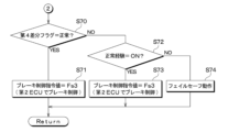
- step S70 the second ECU processing unit 322 determines whether the fourth difference flag is normal. That is, in step S70, the second ECU processing unit 322 determines whether or not both the third sensor 23 and the fourth sensor 24 are in a normal state. If it is determined in step S71 that the fourth difference flag is normal, the second ECU processing unit 322 adjusts the operation amount of the brake pedal 91 based on the detection signals transmitted from the third sensor 23 and the fourth sensor 24. decide. In this embodiment, the third sensor 23 is set to have a higher priority than the fourth sensor 24. Therefore, the second ECU processing unit 322 determines the operation amount of the brake pedal 91 to be the third operation amount Fs3 based on the detection signal transmitted from the third sensor 23, which has a higher priority than the fourth sensor 24. do.
- the third sensor 23 may be set to have a lower priority than the fourth sensor 24.
- the second ECU processing unit 322 determines the operation amount of the brake pedal 91 to be the fourth operation amount Fs4 based on the detection signal transmitted from the fourth sensor 24.
- the second ECU processing unit 322 calculates the target deceleration of the vehicle based on the determined third operation amount Fs3 of the brake pedal 91 and a predetermined control map. Then, the second ECU 32 is connected to the first brake circuit 11 and the second brake circuit 12 by the second ECU switch 323. Furthermore, the first ECU 31 is disconnected from the first brake circuit 11 and the second brake circuit 12 by the first ECU switch 313 . Then, the second ECU 32 controls the first brake circuit 11 and the second brake circuit 12 by outputting information about the calculated target deceleration to the first brake circuit 11 and the second brake circuit 12.
- step S70 determines whether the fourth difference flag is not determined to be normal in step S70. If the fourth difference flag is not determined to be normal in step S70, the second ECU processing unit 322 determines whether the normal experience flag is on in step S72.
- step S73 the second ECU processing unit 322 determines the operation amount of the brake pedal 91 based on the detection signal transmitted from the third sensor 23. . Then, the second ECU processing unit 322 calculates the target deceleration of the vehicle based on the third operation amount Fs3, which is the determined operation amount of the brake pedal 91, and a predetermined control map. Then, the second ECU 32 is connected to the first brake circuit 11 and the second brake circuit 12 by the second ECU switch 323. Furthermore, the first ECU 31 is disconnected from the first brake circuit 11 and the second brake circuit 12 by the first ECU switch 313 . Then, the second ECU 32 controls the first brake circuit 11 and the second brake circuit 12 by outputting information about the calculated target deceleration to the first brake circuit 11 and the second brake circuit 12.
- the normal experience flag is turned on when the fourth sensor 24 is determined to be in a normal state in the majority decision process of the first ECU 31 that is executed after the ignition switch of the vehicle is turned on. Further, the process in step S58 for determining whether or not the normal experience flag can be changed from the initial value OFF to ON is performed when it is determined in step S55 that both the third sensor 23 and the fourth sensor 24 are in a normal state. is executed. Therefore, the fact that the normal experience flag is on indicates that the state of the fourth sensor 24 has been determined to be a normal state by the first ECU 31 and the second ECU 32 after the ignition switch of the vehicle is turned on. When the normal experience flag is turned on, the normal experience flag remains on while the ignition switch of the vehicle is on.
- control initiative is transferred from the first ECU 31 to the second ECU 32 when it is determined that the majority decision has failed in the majority decision processing.
- 24 are connected.
- the first sensor 21, second sensor 22, and fourth sensor 24 will fail at the same time due to external factors.
- the first sensor 21, second sensor 22, and fourth sensor 24 connected to the first ECU 31 have different detection methods. Therefore, there is a very low possibility that the three first sensors 21, second sensors 22, and fourth sensors 24, which have different detection methods from each other, will fail at the same time due to external factors. That is, there is a very low possibility that the majority decision process of the first ECU 31 will be determined to have failed due to simultaneous failure of a plurality of sensors among the three first sensors 21, second sensors 22, and fourth sensors 24.
- step S61 if it is not determined in step S61 that the majority decision flag is not a majority decision failure, it is assumed that two of the first sensor 21, second sensor 22, and fourth sensor 24 have become abnormal at different timings. For example, it is assumed that the second sensor 22 or the fourth sensor 24 becomes abnormal after a predetermined period has passed after the first sensor 21 becomes abnormal, and the majority flag is no longer determined to be a majority failure in step S61. Ru. As another example, if the first sensor 21 or the second sensor 22 becomes abnormal after a predetermined period has passed since the fourth sensor 24 becomes abnormal, the majority decision flag is set to indicate that the majority decision has not failed in step S61. It is assumed that it is no longer judged.
- step S61 For example, assume that the fourth sensor 24 becomes abnormal after a predetermined period of time has passed since the first sensor 21 became abnormal, so that the majority decision flag is no longer determined to be a majority decision failure in step S61. In this case, since the fourth sensor 24 is in an abnormal state, a negative determination is made in step S55. In this case, the fourth difference flag is abnormally changed in the process of step S57. However, the normal experience flag remains on.
- a third sensor 23 and a fourth sensor 24 are connected to the second ECU 32, and the possibility that these third sensor 23 and fourth sensor 24 fail at the same time is relatively small.
- the third sensor 23 and the fourth sensor 24 connected to the second ECU 32 are configured by combining two sensors that detect the operation amount of the brake pedal 91 using different detection methods. Therefore, it is very unlikely that the two third and fourth sensors 23 and 24, which have different detection methods, will fail at the same time due to external factors.
- step S55 when the normal experience flag is on and a negative determination is made in step S55, which is executed in the same control cycle as the control cycle in which a negative determination was made in step S61, only the fourth sensor 24 is in an abnormal state. It is assumed that That is, if the fourth difference flag is not determined to be normal in step S70, the fourth sensor 24 out of the third sensor 23 and the fourth sensor 24 is in an abnormal state, but the third sensor 23 is in a normal state. It can be assumed that
- the first ECU 31 and the second ECU 32 determine that the fourth sensor 24 is in a normal state
- the first ECU 31 determines that the first sensor 21, the second sensor 22, and the fourth sensor 24 are in a normal state.
- the second ECU 32 determines that after the first ECU 31 and the second ECU 32 have determined that the fourth sensor 24 is in a normal state, it is no longer possible to determine that either the third sensor 23 or the fourth sensor 24 is in a normal state. do.
- the fourth sensor 24 commonly connected to the first ECU 31 and the second ECU 32 is in an abnormal state, so that the majority decision process is determined to have failed, and the sensor abnormality determination is determined to be abnormal.
- the third sensor 23, which is different from the fourth sensor 24 which is assumed to be in an abnormal state can be assumed to be in a normal state.
- the second ECU processing unit 322 determines the operation amount of the brake pedal 91 based on the detection signal transmitted from the third sensor 23. I can do it.
- the fourth sensor 24 becomes abnormal first.
- the fourth sensor 24 becomes abnormal, a negative determination is made in step S55, and the fourth difference flag is changed to abnormal in the process of step S57.
- the normal experience flag remains on. It is assumed that the first sensor 21 or the second sensor 22 becomes abnormal after a predetermined period of time has passed since the fourth sensor 24 became abnormal, so that the majority decision flag is no longer determined to be a majority decision failure in step S61. .
- the third sensor 23 is in a normal state. Assume that That is, even if two of the first sensor 21, second sensor 22, and fourth sensor 24 are in an abnormal state, the third sensor 23 will be in a normal state after the ignition switch of the vehicle is turned on. If so, it is assumed that the third sensor 23 is in a normal state.
- the second ECU processing unit 322 determines the operation amount of the brake pedal 91 based on the detection signal transmitted from the third sensor 23. I can do it.
- step S72 the second ECU 32 does not determine the operation amount of the brake pedal 91. Then, in step S74, the second ECU 32 outputs a control signal to the first brake circuit 11 and the second brake circuit 12 for executing a predetermined fail-safe operation. This is because, after the ignition switch of the vehicle is turned on, it cannot be confirmed that the fourth sensor 24, which is commonly connected to the first ECU 31 and the second ECU 32, is in a normal state.
- the fail-safe operation may display a warning of an abnormal brake condition on a display provided on the instrument panel.
- the vehicle may be prohibited from driving.
- the fail-safe operation may include displaying a warning of an abnormal brake condition on a display provided on the instrument panel, or The running speed of the vehicle may be limited.
- the operation amount of the brake pedal 91 is determined as shown in the table shown in FIG. Basically, in the brake system 1 of this embodiment, if the operation amount of the brake pedal 91 can be determined by the first ECU 31 set on the main side, the operation amount of the brake pedal 91 is determined by the control process of the first ECU 31. be done. However, if it is determined that the majority decision has failed in the majority decision processing and the second ECU 32 determines that the third sensor 23 and the fourth sensor 24 are in a normal state, the brake pedal 91 is The amount of operation is determined.
- the brake pedal 91 is activated based on the detection signal of the third sensor 23.
- the manipulated variable is determined.
- the brake system 1 determines that there is a sensor in the normal state based on the third operation amount Fs3. Controls the brake circuit 10.
- the brake circuit 10 can be controlled based on the third operation amount Fs3. . Therefore, redundancy as the brake system 1 can be ensured.
- the first sensor 21, the second sensor 22, and the fourth sensor 24 that detect the operation amount of the brake pedal 91 are directly connected to the first ECU 31, and the third sensor 23 and the fourth sensor 24 are directly connected to the second ECU 32. There is. Therefore, compared to a configuration in which the detection signals of the first sensor 21 to the fourth sensor 24 are transmitted and received through mutual communication between the first ECU 31 and the second ECU 32, there is a delay in synchronization of the detection signals in the control processing of each of the first ECU 31 and the second ECU 32. can suppress the occurrence of
- the fourth sensor 24 is connected to the first ECU 31 and the second ECU 32, and the operation amount of the brake pedal 91 detected by the fourth sensor 24 is transmitted to the first ECU 31 and the second ECU 32. Output to. Therefore, the number of sensors provided in the brake system 1 can be reduced compared to a configuration that does not include sensors commonly connected to the first ECU 31 and the second ECU 32. Therefore, it is possible to suppress an increase in the size of the housing of the brake system 1 and an increase in cost.
- the first ECU 31 and the second ECU 32 determine that the fourth sensor 24 is in a normal state
- the first ECU 31 indicates that the first sensor 21, the second sensor 22, and the fourth sensor 24 are in a normal state. If the second ECU 32 does not determine that there is a sensor in the normal state and neither the third sensor 23 nor the fourth sensor 24 is in the normal state, the first brake is activated based on the operation amount detected by the third sensor 23.
- the circuit 11 and the second brake circuit 12 are controlled.
- the third sensor 24 23 can be assumed to be in a normal state.
- the brake circuit 10 can be controlled based on the third operation amount Fs3. Therefore, redundancy as the brake system 1 can be ensured.
- the first ECU 31 determines whether the fourth sensor 24 is normal based on whether the difference between the operation amounts detected by the first sensor 21, the second sensor 22, and the fourth sensor 24 is within the allowable value. Determine whether the state is the same or not. Then, the second ECU 32 determines whether the fourth sensor 24 is in a normal state based on whether the difference between the operation amounts detected by the third sensor 23 and the fourth sensor 24 is within an allowable value.
- the first ECU 31 and the second ECU 32 are configured to be able to communicate with each other and to be able to send and receive the normal state and abnormal state of each other. Further, when one of the first ECU 31 and the second ECU 32 is in an abnormal state, the first brake circuit 11 and the second brake circuit 12 are controlled based on the operation amount detected by the other ECU.
- the first brake circuit 11 and the second brake circuit 12 can be controlled. Even if the second ECU 32 is in an abnormal state, if the first ECU 31 is in a normal state, the first brake The circuit 11 and the second brake circuit 12 can be controlled.
- the first brake circuit 11 and the second brake circuit 12 are controlled based on the operation amounts calculated by the first ECU 31 and the second ECU 32, respectively. processing speed can be increased.
- the first sensor 21, the second sensor 22, and the fourth sensor 24 include at least two sensors that use different detection methods to detect the operation amount of the brake pedal 91. Further, the third sensor 23 and the fourth sensor 24 have different detection methods for detecting the operation amount of the brake pedal 91.
- the other two sensors Even if one sensor among the first sensor 21, second sensor 22, and fourth sensor 24 cannot detect the operation amount of the brake pedal 91 due to the external environment, the other two sensors The amount of operation of the brake pedal 91 can be detected. Further, among the third sensor 23 and the fourth sensor 24, for example, even if one sensor cannot detect the operation amount of the brake pedal 91 due to the external environment, the other sensor detects the operation amount of the brake pedal 91. be able to.
- the number of sensors connected to the first ECU 31 was three, but the number is not limited to this.
- the first ECU 31 may be connected to four or more sensors. In this case, the first ECU 31 determines that there is a sensor in a normal state among the four or more sensors by executing majority decision processing based on the detection signals transmitted from the four or more sensors.
- the first ECU 31 and the second ECU 32 may be configured such that they cannot transmit and receive information about the normal state and abnormal state of each other.
- the first ECU 31 and the second ECU 32 may transmit the determined operation amount to the first brake circuit 11 and the second brake circuit 12 independently of each other.
- the first brake circuit 11 and the second brake circuit 12 may be configured to perform a fail-safe operation when the determined operation amount cannot be received from either the first ECU 31 or the second ECU 32. Alternatively, when the first brake circuit 11 and the second brake circuit 12 receive the determined operation amount from at least one of the first ECU 31 and the second ECU 32, the first brake circuit 11 and the second brake circuit 12 may operate based on the received operation amount.
- the first brake circuit 11 and the second brake circuit 12 are controlled based on the operation amount detected by the other ECU. has been described, but is not limited thereto.
- the other ECU outputs a control signal to the first brake circuit 11 and the second brake circuit 12 to perform a fail-safe operation. There may be.
- first brake circuit 11 and the second brake circuit 12 are controlled based on the operation amount transmitted to the first ECU 31 when both the first ECU 31 and the second ECU 32 are in a normal state. , but not limited to.
- the first brake circuit 11 and the second brake circuit 12 may be controlled based on the operation amount transmitted to the second ECU 32.
- the target deceleration is calculated based on the operation amount detected by the sensor determined to be in the normal state among the plurality of sensors connected to the first ECU 31.
- the present invention is not limited thereto.
- the target deceleration may be calculated based on the operation amount. For example, if it is determined that all of the first sensor 21 to fourth sensor 24 are in a normal state, the target deceleration is determined based on the average value of the operation amount detected by each of these first sensor 21 to fourth sensor 24. It may be calculated.
- the first sensor 21, the second sensor 22, and the fourth sensor 24 may be configured to use the same detection method for detecting the operation amount of the brake pedal 91.
- the first sensor 21, the second sensor 22, and the fourth sensor 24 have the same detection method in which two of the three sensors detect the operation amount of the brake pedal 91, and the detection method of the remaining one sensor is the same. It may have a different configuration.
- the third sensor 23 and the fourth sensor 24 may be configured to use the same detection method for detecting the operation amount of the brake pedal 91.
- a brake system that controls a brake circuit (10) that brakes a vehicle, four or more sensors (21, 22, 23, 24) that detect the operation amount of the brake pedal (91) operated by the driver and generate and output a detection signal according to the detected operation amount; a first electronic control device (31) to which three or more sensors (21, 22, 24) except one predetermined sensor (23) among the four or more sensors are connected; a second electronic control device (32) to which two sensors of one common sensor (24) of the three or more sensors are connected; an electronic control device (30) that controls the brake circuit based on the brake circuit;
- the first electronic control device is capable of determining that there is a sensor in a normal state among the three or more sensors based on the operation amount detected by each of the three or more sensors,
- the second electronic control device is capable of determining that both of the two sensors are in a normal state based on the operation amount detected by each of the two sensors,
- the electronic control device includes: When the first electronic control unit does not determine that any of the three or
- the electronic control device includes: After the first electronic control device and the second electronic control device determine that the common sensor is in a normal state, the first electronic control device determines that the three or more sensors are in a normal state. If the sensor is not determined to be present and the second electronic control unit does not determine that either of the two sensors is in a normal state, the brake circuit is controlled based on the operation amount detected by the predetermined sensor.
- the brake system according to the first aspect.
- the first electronic control device determines whether or not the common sensor is in a normal state based on whether a difference between the operation amounts detected by the three or more sensors is within a predetermined tolerance. judge, The second electronic control device determines whether the common sensor is in a normal state based on whether a difference between the operation amounts detected by the two sensors is within a predetermined tolerance. Brake system according to the second aspect.
- the first electronic control device and the second electronic control device are configured to be able to communicate with each other and to be able to send and receive normal and abnormal states of each other, When one of the first electronic control device and the second electronic control device is in an abnormal state, a first electronic control device that controls the brake circuit based on the operation amount transmitted to the other electronic control device. 3.
- the brake system according to any one of the third aspects.
- the brake is applied based on the operation amount transmitted to either the first electronic control device or the second electronic control device.
- the brake system according to any one of the first to fourth aspects, which controls the circuit.
- the three or more sensors connected to the first electronic control device include at least two sensors with different detection methods for detecting the operation amount of the brake pedal,
- the brake system according to any one of the first to fifth aspects, wherein the two sensors connected to the second electronic control device have different detection methods for detecting the amount of operation of the brake pedal.
Landscapes
- Engineering & Computer Science (AREA)
- Transportation (AREA)
- Mechanical Engineering (AREA)
- Valves And Accessory Devices For Braking Systems (AREA)
- Regulating Braking Force (AREA)
Abstract
Description
コンピュータ装置は、第1の測定装置の測定結果および第2の測定装置の測定結果のうち、モニタ要素によって正常に機能していると判定された測定装置の測定結果に基づいてブレーキの目標値を求める。これにより、車両を制動するブレーキ回路を制御するブレーキシステムとしての冗長性を確保している。以下、ブレーキペダルの測定を行う測定装置をセンサとも呼ぶ。
車両を制動するブレーキ回路を制御するブレーキシステムであって、
運転者に操作されるブレーキペダルの操作量を検出し、検出した操作量に応じた検出信号を生成して出力する4つ以上のセンサと、
4つ以上のセンサのうちの1つの所定のセンサを除く3つ以上のセンサが接続される第1電子制御装置と、所定のセンサおよび3つ以上のセンサのうちの1つの共通のセンサの2つのセンサが接続される第2電子制御装置とを含み、4つ以上のセンサが検出する操作量に基づいてブレーキ回路を制御する電子制御装置と、を備え、
第1電子制御装置は、3つ以上のセンサそれぞれが検出する操作量に基づいて、3つ以上のセンサに正常状態であるセンサが存在することを判定可能であって、
第2電子制御装置は、2つのセンサそれぞれが検出する操作量に基づいて、2つのセンサのいずれも正常状態であることを判定可能であって、
電子制御装置は、
第1電子制御装置が、3つ以上のセンサに正常状態であるセンサが存在すると判定せず、第2電子制御装置が、2つのセンサのいずれも正常状態であると判定する場合、所定のセンサおよび共通のセンサのうち少なくとも一方のセンサが検出する操作量に基づいてブレーキ回路を制御する。
以上、本開示の代表的な実施形態について説明したが、本開示は、上述の実施形態に限定されることなく、例えば、以下のように種々変形可能である。
[第1の観点]
車両を制動するブレーキ回路(10)を制御するブレーキシステムであって、
運転者に操作されるブレーキペダル(91)の操作量を検出し、検出した前記操作量に応じた検出信号を生成して出力する4つ以上のセンサ(21、22、23、24)と、
前記4つ以上のセンサのうちの1つの所定のセンサ(23)を除く3つ以上のセンサ(21、22、24)が接続される第1電子制御装置(31)と、前記所定のセンサおよび前記3つ以上のセンサのうちの1つの共通のセンサ(24)の2つのセンサが接続される第2電子制御装置(32)とを含み、前記4つ以上のセンサが検出する前記操作量に基づいて前記ブレーキ回路を制御する電子制御装置(30)と、を備え、
前記第1電子制御装置は、前記3つ以上のセンサそれぞれが検出する前記操作量に基づいて、前記3つ以上のセンサに正常状態であるセンサが存在することを判定可能であって、
前記第2電子制御装置は、前記2つのセンサそれぞれが検出する前記操作量に基づいて、前記2つのセンサのいずれも正常状態であることを判定可能であって、
前記電子制御装置は、
前記第1電子制御装置が、前記3つ以上のセンサに正常状態であるセンサが存在すると判定せず、前記第2電子制御装置が、前記2つのセンサのいずれも正常状態であると判定する場合、前記所定のセンサおよび前記共通のセンサのうち少なくとも一方のセンサが検出する前記操作量に基づいて前記ブレーキ回路を制御するブレーキシステム。
前記電子制御装置は、
前記第1電子制御装置および前記第2電子制御装置によって前記共通のセンサが正常状態であると判定された後状態で、前記第1電子制御装置が、前記3つ以上のセンサに正常状態であるセンサが存在すると判定せず、前記第2電子制御装置が、前記2つのセンサのいずれも正常状態であると判定しない場合、前記所定のセンサが検出する前記操作量に基づいて前記ブレーキ回路を制御する第1の観点に記載のブレーキシステム。
前記第1電子制御装置は、前記3つ以上のセンサが検出する前記操作量それぞれの差が予め定められる許容誤差以内か否かに基づいて、前記共通のセンサが正常状態であるか否かを判定し、
前記第2電子制御装置は、前記2つのセンサが検出する前記操作量それぞれの差が予め定められる許容誤差以内か否かに基づいて、前記共通のセンサが正常状態であるか否かを判定する第2の観点に記載のブレーキシステム。
前記第1電子制御装置および前記第2電子制御装置は、相互通信可能であって、互いの正常状態および異常状態を送受信可能に構成されており、
前記第1電子制御装置および前記第2電子制御装置のうち一方の電子制御装置が異常状態である場合、他方の電子制御装置に送信される前記操作量に基づいて前記ブレーキ回路を制御する第1ないし第3の観点のいずれか1つに記載のブレーキシステム。
前記第1電子制御装置および前記第2電子制御装置のいずれも正常状態である場合、前記第1電子制御装置および前記第2電子制御装置のどちらか一方に送信される前記操作量に基づいてブレーキ回路を制御する第1ないし第4の観点のいずれか1つに記載のブレーキシステム。
前記第1電子制御装置に接続される前記3つ以上のセンサは、前記ブレーキペダルの操作量を検出する検出方式が互いに異なるセンサを少なくとも2つ含み、
前記第2電子制御装置に接続される前記2つのセンサは、前記ブレーキペダルの操作量を検出する検出方式が互いに異なる第1ないし第5の観点のいずれ1つに記載のブレーキシステム。
Claims (6)
- 車両を制動するブレーキ回路(10)を制御するブレーキシステムであって、
運転者に操作されるブレーキペダル(91)の操作量を検出し、検出した前記操作量に応じた検出信号を生成して出力する4つ以上のセンサ(21、22、23、24)と、
前記4つ以上のセンサのうちの1つの所定のセンサ(23)を除く3つ以上のセンサ(21、22、24)が接続される第1電子制御装置(31)と、前記所定のセンサおよび前記3つ以上のセンサのうちの1つの共通のセンサ(24)の2つのセンサが接続される第2電子制御装置(32)とを含み、前記4つ以上のセンサが検出する前記操作量に基づいて前記ブレーキ回路を制御する電子制御装置(30)と、を備え、
前記第1電子制御装置は、前記3つ以上のセンサそれぞれが検出する前記操作量に基づいて、前記3つ以上のセンサに正常状態であるセンサが存在することを判定可能であって、
前記第2電子制御装置は、前記2つのセンサそれぞれが検出する前記操作量に基づいて、前記2つのセンサのいずれも正常状態であることを判定可能であって、
前記電子制御装置は、
前記第1電子制御装置が、前記3つ以上のセンサに正常状態であるセンサが存在すると判定せず、前記第2電子制御装置が、前記2つのセンサのいずれも正常状態であると判定する場合、前記所定のセンサおよび前記共通のセンサのうち少なくとも一方のセンサが検出する前記操作量に基づいて前記ブレーキ回路を制御するブレーキシステム。 - 前記電子制御装置は、
前記第1電子制御装置および前記第2電子制御装置によって前記共通のセンサが正常状態であると判定された後状態で、前記第1電子制御装置が、前記3つ以上のセンサに正常状態であるセンサが存在すると判定せず、前記第2電子制御装置が、前記2つのセンサのいずれも正常状態であると判定しない場合、前記所定のセンサが検出する前記操作量に基づいて前記ブレーキ回路を制御する請求項1に記載のブレーキシステム。 - 前記第1電子制御装置は、前記3つ以上のセンサが検出する前記操作量それぞれの差が予め定められる許容誤差以内か否かに基づいて、前記共通のセンサが正常状態であるか否かを判定し、
前記第2電子制御装置は、前記2つのセンサが検出する前記操作量それぞれの差が予め定められる許容誤差以内か否かに基づいて、前記共通のセンサが正常状態であるか否かを判定する請求項2に記載のブレーキシステム。 - 前記第1電子制御装置および前記第2電子制御装置は、相互通信可能であって、互いの正常状態および異常状態を送受信可能に構成されており、
前記第1電子制御装置および前記第2電子制御装置のうち一方の電子制御装置が異常状態である場合、他方の電子制御装置に送信される前記操作量に基づいて前記ブレーキ回路を制御する請求項1ないし3のいずれか1つに記載のブレーキシステム。 - 前記第1電子制御装置および前記第2電子制御装置のいずれも正常状態である場合、前記第1電子制御装置および前記第2電子制御装置のどちらか一方に送信される前記検出信号に基づいて前記ブレーキ回路を制御する請求項4に記載のブレーキシステム。
- 前記第1電子制御装置に接続される前記3つ以上のセンサは、前記ブレーキペダルの前記操作量を検出する検出方式が互いに異なるセンサを少なくとも2つ含み、
前記第2電子制御装置に接続される前記2つのセンサは、前記ブレーキペダルの前記操作量を検出する検出方式が互いに異なる請求項1に記載のブレーキシステム。
Priority Applications (3)
| Application Number | Priority Date | Filing Date | Title |
|---|---|---|---|
| DE112023002069.8T DE112023002069T5 (de) | 2022-04-29 | 2023-04-27 | Bremssystem |
| CN202380036480.4A CN119095750A (zh) | 2022-04-29 | 2023-04-27 | 制动系统 |
| US18/917,281 US20250033613A1 (en) | 2022-04-29 | 2024-10-16 | Brake system |
Applications Claiming Priority (2)
| Application Number | Priority Date | Filing Date | Title |
|---|---|---|---|
| JP2022075562A JP7609121B2 (ja) | 2022-04-29 | 2022-04-29 | ブレーキシステム |
| JP2022-075562 | 2022-04-29 |
Related Child Applications (1)
| Application Number | Title | Priority Date | Filing Date |
|---|---|---|---|
| US18/917,281 Continuation US20250033613A1 (en) | 2022-04-29 | 2024-10-16 | Brake system |
Publications (1)
| Publication Number | Publication Date |
|---|---|
| WO2023210766A1 true WO2023210766A1 (ja) | 2023-11-02 |
Family
ID=88518833
Family Applications (1)
| Application Number | Title | Priority Date | Filing Date |
|---|---|---|---|
| PCT/JP2023/016714 Ceased WO2023210766A1 (ja) | 2022-04-29 | 2023-04-27 | ブレーキシステム |
Country Status (5)
| Country | Link |
|---|---|
| US (1) | US20250033613A1 (ja) |
| JP (1) | JP7609121B2 (ja) |
| CN (1) | CN119095750A (ja) |
| DE (1) | DE112023002069T5 (ja) |
| WO (1) | WO2023210766A1 (ja) |
Cited By (1)
| Publication number | Priority date | Publication date | Assignee | Title |
|---|---|---|---|---|
| US12491846B2 (en) | 2022-04-29 | 2025-12-09 | Denso Corporation | Pedal device |
Citations (5)
| Publication number | Priority date | Publication date | Assignee | Title |
|---|---|---|---|---|
| JPH1159389A (ja) * | 1997-08-12 | 1999-03-02 | Toyota Motor Corp | ブレーキ液圧制御装置 |
| JP2002012135A (ja) * | 2000-04-28 | 2002-01-15 | Tokico Ltd | 電動ブレーキシステム |
| JP2007223430A (ja) * | 2006-02-22 | 2007-09-06 | Toyota Motor Corp | インホイールモータ車用のブレーキ装置 |
| JP2009029416A (ja) * | 2007-07-27 | 2009-02-12 | Robert Bosch Gmbh | ブレーキ装置 |
| JP2010254298A (ja) * | 1999-08-06 | 2010-11-11 | Robert Bosch Gmbh | 電気制御式ブレーキ装置 |
Family Cites Families (6)
| Publication number | Priority date | Publication date | Assignee | Title |
|---|---|---|---|---|
| DE19510525A1 (de) | 1995-03-23 | 1996-09-26 | Bosch Gmbh Robert | Verfahren und Vorrichtung zur Steuerung bzw. Regelung der Bremsanlage eines Fahrzeugs |
| DE102006017302B4 (de) * | 2006-04-12 | 2012-02-16 | Continental Automotive Gmbh | Verfahren und System zur Kontrolle einer Signalübertragung eines elektrischen Pedals |
| US11736823B2 (en) | 2020-11-03 | 2023-08-22 | Samsung Electronics Co., Ltd. | Integrated high-speed image sensor and operation method thereof |
| DE112022004244T5 (de) * | 2021-09-01 | 2024-06-20 | Denso Corporation | Bremspedalvorrichtung und Bremssystem |
| JP7643301B2 (ja) * | 2021-11-10 | 2025-03-11 | 株式会社デンソー | ブレーキシステムおよびブレーキペダル装置 |
| JP7537410B2 (ja) * | 2021-11-10 | 2024-08-21 | 株式会社デンソー | ブレーキシステムおよびブレーキペダル装置 |
-
2022
- 2022-04-29 JP JP2022075562A patent/JP7609121B2/ja active Active
-
2023
- 2023-04-27 WO PCT/JP2023/016714 patent/WO2023210766A1/ja not_active Ceased
- 2023-04-27 CN CN202380036480.4A patent/CN119095750A/zh active Pending
- 2023-04-27 DE DE112023002069.8T patent/DE112023002069T5/de active Pending
-
2024
- 2024-10-16 US US18/917,281 patent/US20250033613A1/en active Pending
Patent Citations (5)
| Publication number | Priority date | Publication date | Assignee | Title |
|---|---|---|---|---|
| JPH1159389A (ja) * | 1997-08-12 | 1999-03-02 | Toyota Motor Corp | ブレーキ液圧制御装置 |
| JP2010254298A (ja) * | 1999-08-06 | 2010-11-11 | Robert Bosch Gmbh | 電気制御式ブレーキ装置 |
| JP2002012135A (ja) * | 2000-04-28 | 2002-01-15 | Tokico Ltd | 電動ブレーキシステム |
| JP2007223430A (ja) * | 2006-02-22 | 2007-09-06 | Toyota Motor Corp | インホイールモータ車用のブレーキ装置 |
| JP2009029416A (ja) * | 2007-07-27 | 2009-02-12 | Robert Bosch Gmbh | ブレーキ装置 |
Cited By (1)
| Publication number | Priority date | Publication date | Assignee | Title |
|---|---|---|---|---|
| US12491846B2 (en) | 2022-04-29 | 2025-12-09 | Denso Corporation | Pedal device |
Also Published As
| Publication number | Publication date |
|---|---|
| DE112023002069T5 (de) | 2025-03-13 |
| US20250033613A1 (en) | 2025-01-30 |
| JP2023164180A (ja) | 2023-11-10 |
| JP7609121B2 (ja) | 2025-01-07 |
| CN119095750A (zh) | 2024-12-06 |
Similar Documents
| Publication | Publication Date | Title |
|---|---|---|
| US6969127B2 (en) | Electric parking brake system | |
| JP3705808B2 (ja) | 電子式ブレーキ装置 | |
| US6317675B1 (en) | Electromechanical brake system | |
| GB2316726A (en) | Electronic brake system | |
| JP2001097193A (ja) | 車両内の電気制御式分散形制御装置 | |
| US20240286589A1 (en) | Brake system and brake pedal device | |
| JP2010254298A (ja) | 電気制御式ブレーキ装置 | |
| EP1588924A2 (en) | Vehicle controller | |
| US11801812B2 (en) | Vehicle control apparatus and method for controlling the same | |
| JP7778938B2 (ja) | ブレーキシステムを動作させるための方法及びブレーキシステム | |
| WO2023210766A1 (ja) | ブレーキシステム | |
| US20250010840A1 (en) | Method for activating a sensor system, sensor system, vehicle, computer program product, and storage medium | |
| KR102690454B1 (ko) | 차량의 이중화 시스템과, 그 전원 공급 장치 및 방법 | |
| US10458539B2 (en) | Vehicle control device | |
| JP7537410B2 (ja) | ブレーキシステムおよびブレーキペダル装置 | |
| US12384342B2 (en) | Braking control device for vehicle | |
| US20250100571A1 (en) | X-by-wire control system for a motor vehicle | |
| US20260109369A1 (en) | Motor vehicle, method for operating a motor vehicle | |
| US20250381966A1 (en) | Method and operating system for a vehicle | |
| US12319256B2 (en) | Fault detection arrangement for vehicle brake system | |
| JP2025069055A (ja) | アクチュエータアッセンブリを運転する方法、アクチュエータアッセンブリ、自動車 | |
| CN121626253A (zh) | 转向系统和用于操作机动车的转向系统的方法 | |
| KR20180024233A (ko) | 차량의 브레이크 제어 장치 및 그 방법 | |
| CN117445874A (zh) | 用于运行机动车制动设备的方法以及相应的制动设备 | |
| CN121084595A (zh) | 一种电传飞控操纵系统、方法及电动飞行器 |
Legal Events
| Date | Code | Title | Description |
|---|---|---|---|
| 121 | Ep: the epo has been informed by wipo that ep was designated in this application |
Ref document number: 23796501 Country of ref document: EP Kind code of ref document: A1 |
|
| WWE | Wipo information: entry into national phase |
Ref document number: 202380036480.4 Country of ref document: CN |
|
| WWE | Wipo information: entry into national phase |
Ref document number: 112023002069 Country of ref document: DE |
|
| WWP | Wipo information: published in national office |
Ref document number: 112023002069 Country of ref document: DE |
|
| 122 | Ep: pct application non-entry in european phase |
Ref document number: 23796501 Country of ref document: EP Kind code of ref document: A1 |