WO2023210594A1 - 画像符号化装置及び画像符号化方法 - Google Patents
画像符号化装置及び画像符号化方法 Download PDFInfo
- Publication number
- WO2023210594A1 WO2023210594A1 PCT/JP2023/016152 JP2023016152W WO2023210594A1 WO 2023210594 A1 WO2023210594 A1 WO 2023210594A1 JP 2023016152 W JP2023016152 W JP 2023016152W WO 2023210594 A1 WO2023210594 A1 WO 2023210594A1
- Authority
- WO
- WIPO (PCT)
- Prior art keywords
- data
- scale factor
- code amount
- component
- target code
- Prior art date
- Legal status (The legal status is an assumption and is not a legal conclusion. Google has not performed a legal analysis and makes no representation as to the accuracy of the status listed.)
- Ceased
Links
Images











Classifications
-
- H—ELECTRICITY
- H04—ELECTRIC COMMUNICATION TECHNIQUE
- H04N—PICTORIAL COMMUNICATION, e.g. TELEVISION
- H04N19/00—Methods or arrangements for coding, decoding, compressing or decompressing digital video signals
- H04N19/10—Methods or arrangements for coding, decoding, compressing or decompressing digital video signals using adaptive coding
- H04N19/102—Methods or arrangements for coding, decoding, compressing or decompressing digital video signals using adaptive coding characterised by the element, parameter or selection affected or controlled by the adaptive coding
- H04N19/124—Quantisation
- H04N19/126—Details of normalisation or weighting functions, e.g. normalisation matrices or variable uniform quantisers
-
- H—ELECTRICITY
- H04—ELECTRIC COMMUNICATION TECHNIQUE
- H04N—PICTORIAL COMMUNICATION, e.g. TELEVISION
- H04N19/00—Methods or arrangements for coding, decoding, compressing or decompressing digital video signals
- H04N19/10—Methods or arrangements for coding, decoding, compressing or decompressing digital video signals using adaptive coding
- H04N19/102—Methods or arrangements for coding, decoding, compressing or decompressing digital video signals using adaptive coding characterised by the element, parameter or selection affected or controlled by the adaptive coding
- H04N19/115—Selection of the code volume for a coding unit prior to coding
-
- H—ELECTRICITY
- H04—ELECTRIC COMMUNICATION TECHNIQUE
- H04N—PICTORIAL COMMUNICATION, e.g. TELEVISION
- H04N19/00—Methods or arrangements for coding, decoding, compressing or decompressing digital video signals
- H04N19/10—Methods or arrangements for coding, decoding, compressing or decompressing digital video signals using adaptive coding
- H04N19/134—Methods or arrangements for coding, decoding, compressing or decompressing digital video signals using adaptive coding characterised by the element, parameter or criterion affecting or controlling the adaptive coding
- H04N19/136—Incoming video signal characteristics or properties
-
- H—ELECTRICITY
- H04—ELECTRIC COMMUNICATION TECHNIQUE
- H04N—PICTORIAL COMMUNICATION, e.g. TELEVISION
- H04N19/00—Methods or arrangements for coding, decoding, compressing or decompressing digital video signals
- H04N19/10—Methods or arrangements for coding, decoding, compressing or decompressing digital video signals using adaptive coding
- H04N19/169—Methods or arrangements for coding, decoding, compressing or decompressing digital video signals using adaptive coding characterised by the coding unit, i.e. the structural portion or semantic portion of the video signal being the object or the subject of the adaptive coding
- H04N19/17—Methods or arrangements for coding, decoding, compressing or decompressing digital video signals using adaptive coding characterised by the coding unit, i.e. the structural portion or semantic portion of the video signal being the object or the subject of the adaptive coding the unit being an image region, e.g. an object
- H04N19/176—Methods or arrangements for coding, decoding, compressing or decompressing digital video signals using adaptive coding characterised by the coding unit, i.e. the structural portion or semantic portion of the video signal being the object or the subject of the adaptive coding the unit being an image region, e.g. an object the region being a block, e.g. a macroblock
-
- H—ELECTRICITY
- H04—ELECTRIC COMMUNICATION TECHNIQUE
- H04N—PICTORIAL COMMUNICATION, e.g. TELEVISION
- H04N19/00—Methods or arrangements for coding, decoding, compressing or decompressing digital video signals
- H04N19/10—Methods or arrangements for coding, decoding, compressing or decompressing digital video signals using adaptive coding
- H04N19/169—Methods or arrangements for coding, decoding, compressing or decompressing digital video signals using adaptive coding characterised by the coding unit, i.e. the structural portion or semantic portion of the video signal being the object or the subject of the adaptive coding
- H04N19/186—Methods or arrangements for coding, decoding, compressing or decompressing digital video signals using adaptive coding characterised by the coding unit, i.e. the structural portion or semantic portion of the video signal being the object or the subject of the adaptive coding the unit being a colour or a chrominance component
Definitions
- the present disclosure relates to an image encoding device and an image encoding method.
- Patent Document 1 discloses that in order to prevent the code length of a block including a plurality of groups from exceeding a predetermined value, a quantization step and an encoding method are determined for each group, and the determined quantization step and encoding method are It is disclosed that encoded data is generated by performing encoding processing based on the following.
- Patent Document 2 discloses that image data is compressed by either a first compression algorithm with a fixed scale factor or a second compression algorithm with an adjustable scale factor, and the amount of code is within a predetermined range. It is disclosed that determining whether
- the present disclosure provides an image encoding device and an image encoding method that can suppress image quality deterioration.
- An image encoding device has a feature of acquiring, for each of a plurality of components constituting a pixel of an image, a feature amount of data of the component in a processing target block among a plurality of blocks of the image.
- an amount acquisition unit a target code amount determiner that determines a target code amount of the data of the component for each of the plurality of components according to the feature amount of the data of the component; and for each of the plurality of components, a frequency converter that performs frequency conversion on the data of the component; and a quantizer that quantizes, for each of the plurality of components, the data of the component after frequency conversion according to the target code amount of the data of the component.
- an encoder that encodes, for each of the plurality of components, the data of the component after quantization.
- an image encoding method acquires, for each of a plurality of components constituting a pixel of an image, a feature amount of data of the component in a processing target block among a plurality of blocks of the image. for each of the plurality of components, determining a target code amount of the data of the component according to the feature amount of the data of the component; and for each of the plurality of components, determining the target code amount of the data of the component; for each of the plurality of components, quantizing the data of the component after frequency conversion according to the target code amount of the data of the component; for each, encoding the data of that component after quantization.
- the image encoding device and image encoding method according to one aspect of the present disclosure can suppress image quality deterioration.
- FIG. 2 is a block diagram showing the configuration of an image encoding device in a reference example. It is a flowchart which shows the operation of the image encoding device in a reference example.
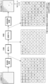
- FIG. 3 is a diagram showing a standard quantization table used for luminance data.
- FIG. 3 is a diagram showing a standard quantization table used for color difference data.
- FIG. 7 is a conceptual diagram showing an example of compression of luminance data and color difference data in a reference example.
- FIG. 2 is a conceptual diagram showing mosquito noise caused by quantization errors.
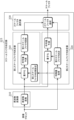
- FIG. 1 is a block diagram showing the configuration of an image encoding device in an embodiment. It is a flowchart showing the operation of the image encoding device in the embodiment.
- FIG. 1 is a block diagram showing the configuration of an image encoding device in an embodiment. It is a flowchart showing the operation of the image encoding device in the embodiment.
- FIG. 1 is a block diagram showing the configuration of an image encoding device in an embodiment.
- FIG. 3 is a conceptual diagram showing an example of calculating a feature amount of brightness data.
- FIG. 3 is a conceptual diagram showing an example of calculating feature amounts of color difference data.
- FIG. 3 is a conceptual diagram showing a first method for determining a scale factor.
- 3 is a flowchart showing a first method for determining a scale factor.
- FIG. 7 is a conceptual diagram showing a second method for determining a scale factor. 7 is a flowchart showing a second method for determining a scale factor.
- FIG. 7 is a conceptual diagram showing a third method for determining a scale factor. It is a flowchart which shows the 3rd determination method of a scale factor. It is a conceptual diagram which shows the 4th determination method of a scale factor.
- FIG. 1 is a block diagram showing the configuration of an image processing device in an embodiment.
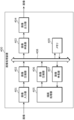
- FIG. 2 is a block diagram showing the configuration of an image compressor in an embodiment.
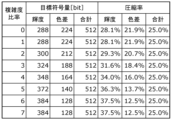
- FIG. 3 is a diagram showing a reference table of complexity ratio and target code amount. It is a graph showing the relationship between complexity ratio and compression rate.
- It is a flowchart showing the operation of the image compressor in the embodiment.
- It is a conceptual diagram which shows the 2nd compression example in embodiment.
- FIG. 2 is a block diagram showing the configuration of an image decompressor in an embodiment. It is a figure showing an image quality evaluation result.
- an image encoding device for each of a plurality of components that constitute a pixel of an image, provides a feature amount of data of the component in a processing target block among a plurality of blocks of the image.
- a target code amount determiner that determines, for each of the plurality of components, a target code amount of the data of the component according to the feature amount of the data of the component;
- a frequency converter performs frequency conversion on the data of the component, and for each of the plurality of components, the data of the component after frequency conversion is converted according to the target code amount of the data of the component. It includes a quantization processor that quantizes, and an encoder that encodes the data of the component after quantization for each of the plurality of components.
- the image encoding device can adjust the target code amount of the data of each component according to the feature amount of the data of each component. Therefore, the image encoding device can suppress significant loss of features. Therefore, the image encoding device can suppress image quality deterioration.
- the plurality of components include two components: luminance and color difference.
- the image encoding device can adjust the target code amount of the data of each component of luminance and chrominance according to the feature amount of the data of the component. Therefore, the image encoding device can appropriately suppress image quality deterioration for images with different feature amounts between luminance and color difference.
- the plurality of components include three components: red, green, and blue.
- the image encoding device can adjust the target code amount of the data of each of the red, green, and blue components according to the feature amount of the data of the component. Therefore, the image encoding device can appropriately suppress image quality deterioration for images in which feature amounts differ between red, green, and blue.
- the plurality of components include transparency.
- the image encoding device can suppress the memory capacity required to hold transparency information when blending multiple images using RGBA and the delay that occurs in transmitting the data.
- the feature amount acquisition device obtains, as the feature amount of the data of the component, a statistical value of an absolute value of a difference between adjacent pixels in the data of the component.
- the image encoding device can acquire feature amounts corresponding to steep changes between adjacent pixels. Therefore, the image encoding device can appropriately adjust the target code amount according to the feature amount corresponding to a sudden change between adjacent pixels.
- the feature amount acquisition device obtains the feature amount of the data of each of the plurality of components using Hadamard transformation.
- the image encoding device can acquire the feature amount corresponding to the amount of edges obtained by Hadamard transform. Therefore, the image encoding device can appropriately adjust the target code amount according to the feature amount corresponding to the amount of edges and the like.
- the feature amount acquisition unit acquires, for each of the plurality of components, information indicating the feature amount of the data of the component from a device external to the image encoding device.
- the feature quantity of the data is acquired.
- the image encoding device can acquire the feature amount without calculating the feature amount. Therefore, the image encoding device can reduce calculation processing.
- the encoder multiplexes identification codes indicating a plurality of target code amounts determined for the plurality of components into a stream, and a plurality of data encoded for the plurality of components, and Output a stream.
- the image encoding device can indicate the target code amount of data of each component in the stream. Therefore, the image encoding device can assist in decoding each component's data from the stream.
- the quantization processor determines a scale factor that affects the quantization width for each of the plurality of components according to the target code amount, and quantizes the data of the component according to the scale factor. .
- the image encoding device can adjust the scale factor used for quantizing the data of each component according to the target code amount of the data of each component. Therefore, the image encoding device can appropriately adjust the code amount of the data of each component according to the target code amount of the data of each component.
- the quantization processor initializes the scale factor, quantizes the data according to the scale factor, and obtains a predicted code amount of the data according to the data quantized according to the scale factor. , updating the scale factor according to a comparison result between the predicted code amount and the target code amount, quantizing the data until the predicted code amount matches the target code amount, and obtaining the predicted code amount; Then, the scale factor is determined by repeating the update of the scale factor.
- the image encoding device can search and determine a scale factor that makes the predicted code amount match the target code amount. Therefore, the image encoding device can determine an appropriate scale factor for the target code amount.
- the quantization processor initializes the scale factor according to the feature amount of the data.
- the image encoding device can appropriately initialize the scale factor in the search for the scale factor, and can suppress processing delays.
- the quantization processor may set the initial value of the scale factor to the initial value of the scale factor. and if the difference is less than or equal to the threshold, the initial value of the scale factor is not updated.
- the quantization processor may count the count value when the difference between the scale factor determined by repeatedly updating the scale factor and the initial value of the scale factor is larger than a first threshold value. and if the difference is less than or equal to the first threshold, the count value is not counted up, and if the count value is greater than the second threshold, the initial value of the scale factor is updated and the count value is If it is less than or equal to the second threshold, the initial value of the scale factor is not updated.
- the image encoding device can update the initial value of the scale factor determined according to the feature amount at an appropriate update frequency based on the final scale factor, resulting in processing delay in subsequent processing. can be suppressed.
- the quantization processor initializes a first scale factor, quantizes the data according to the first scale factor, and quantizes the data according to the data quantized according to the first scale factor. obtaining one predicted code amount, updating the first scale factor according to a comparison result between the first predicted code amount and the target code amount, until the first predicted code amount matches the target code amount,
- the first scale factor is determined by repeating the quantization of the data, the acquisition of the first predicted code amount, and the update of the first scale factor, and the second scale factor is determined according to the feature amount of the data.
- quantize the data according to the second scale factor quantize the data according to the second scale factor, obtain a second predicted code amount of the data according to the data quantized according to the second scale factor, and calculate the first predicted code amount and the Determining one of the first scale factor and the second scale factor as the scale factor based on a comparison result with a target code amount and a comparison result between the second predicted code amount and the target code amount. do.
- the image encoding device uses both a method of searching for a scale factor such that the predicted code amount matches the target code amount and a method of determining the scale factor based on the feature amount. can be determined. Therefore, the image encoding device can prevent the scale factor corresponding to the local solution in the search from being determined as the final scale factor.
- the quantization processor initializes the first scale factor according to the feature amount of the data.
- the image encoding device can appropriately initialize the scale factor in the search for the scale factor, and can suppress processing delays.
- a feature amount of data of the component in a processing target block among a plurality of blocks of the image for each of the plurality of components, determining a target code amount of the data of the component according to the feature amount of the data of the component; performing frequency conversion on the data; for each of the plurality of components, quantizing the data of the component after frequency conversion according to the target code amount of the data of the component; for each component, encoding the data of that component after quantization.
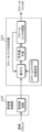
- FIG. 1 is a block diagram showing the configuration of an image encoding device in a reference example.
- the image encoding apparatus 100 shown in FIG. 1 encodes an image block by block. Each image is composed of a plurality of pixels, and each block is also composed of a plurality of pixels.
- the block may be a randomly accessible unit of area called an MCU (Minimum Coded Unit). For example, a 16 ⁇ 8 pixel MCU may be used as a block.
- the image encoding device 100 performs fixed length compression on each block of the image according to the target code amount.
- pixels of an image are composed of multiple components such as luminance and color difference.
- the image encoding apparatus 100 encodes the block of the image component by component.
- the image encoding device 100 independently encodes luminance data and color difference data in a block.
- the image encoding device 100 includes a frequency converter 110, a quantization processor 120, and an encoder 130. Further, the quantization processor 120 includes a quantizer 121 , a quantization table deriver 122 , and a scale factor determiner 123 . For example, these components are electrical circuits.
- the frequency converter 110 performs frequency conversion on data of each component constituting a pixel in the processing target block.
- DCT Discrete Cosine Transform
- a plurality of pixel values of the component in the processing target block are converted into a plurality of frequency coefficients of the corresponding component in the processing target block.
- the quantization processor 120 quantizes the transformed data of the component in the processing target block according to the same fixed target code amount for multiple components. This compresses the data.
- the scale factor determiner 123 determines the scale factor according to the target code amount, the converted data, and the fixed length encoding algorithm so that the data code amount matches the target code amount.
- Quantization table deriver 122 derives a quantization table according to the scale factor.
- the quantizer 121 quantizes the converted data according to the quantization table.
- the quantization width is defined for each frequency level.
- the scale factor affects the quantization width defined for each frequency level in the quantization table. For example, as the scale factor increases, the quantization width also increases. That is, the quantization width may have a monotonically increasing relationship with the scale factor in a narrow or broad sense. Further, the quantization width may be proportional to the scale factor. Note that a scale factor may be used in which the larger the scale factor, the smaller the quantization width.
- the encoder 130 For each component, the encoder 130 encodes the quantized data of the component in the block to be processed into a stream. Huffman codes may be used for encoding. Furthermore, the encoder 130 may feed back the code amount to the scale factor determiner 123. The scale factor determiner 123 may then determine the scale factor again by updating the scale factor according to the amount of code. Determination of the scale factor, derivation of the quantization table, quantization and encoding may then be repeated.
- the block to be processed is encoded according to the target code amount.
- the target code amount may be a register setting value set in the image encoding device 100. Specifically, a compression rate such as 50% or 25% may be used as the target code amount.
- the compression ratio is the ratio of the capacity of compressed data to the capacity of uncompressed data.
- the code amount of each component data in each block of an image is controlled according to the same fixed target code amount.
- the code amount of luminance data and the code amount of color difference data are controlled according to the same fixed target code amount.
- a scale factor for luminance data is determined according to a fixed target code amount.
- the luminance data is then quantized and encoded according to a scale factor for the luminance data.
- a scale factor for color difference data is determined according to the same fixed target code amount.
- the color difference data is then quantized and encoded according to a scale factor for the color difference data.
- FIG. 2 is a flowchart showing the operation of the image encoding device 100 shown in FIG. 1.
- an image is divided into a plurality of blocks (S101).
- This division process (S101) may be performed by a divider (not shown) of the image encoding device 100, or may be performed by the frequency converter 110.
- loop processing (S102 to S106) is performed on a block-by-block basis.
- the frequency converter 110 performs frequency conversion on the data of each component in the processing target block (S102).
- the quantization processor 120 quantizes the transformed data of the component in the processing target block according to the scale factor (S103).
- the encoder 130 encodes the quantized data of the component in the processing target block (S104).
- the quantization processor 120 updates the scale factor (S106).
- the quantization processor 120 increases the scale factor. Then, when the generated code amount is smaller than the target code amount, the quantization processor 120 reduces the scale factor. Then, quantization (S103), encoding (S104), and updating of the scale factor (S106) are repeated until the generated code amount matches the target code amount.
- the block to be processed is encoded according to the target code amount. Further, the image encoding device 100 performs quantization (S103), encoding (S104), updating of the scale factor (S106), etc. for each component. On the other hand, the image encoding device 100 controls the generated code amount using the same fixed target code amount for a plurality of components.
- the quantization table deriving unit 122 may derive the quantization table by reflecting the scale factor on the standard quantization table. Further, a standard quantization table may be defined for each component.
- FIG. 3A is a diagram showing a standard quantization table used for luminance data.
- a quantization width is defined for each frequency level.
- the numbers in the quantization table indicate the quantization width.
- the upper left corresponds to low frequencies, and the lower right corresponds to high frequencies.
- the quantization width is basically set to be small for low frequencies and large for high frequencies. This suppresses subjective image quality deterioration and reduces the amount of code.
- FIG. 3B is a diagram showing a standard quantization table used for color difference data. Similar to FIG. 3A, in FIG. 3B, the numbers in the quantization table indicate the quantization width. People have different senses of brightness and color difference. According to the difference in human sensitivity to brightness and color difference, a quantization table different from the standard quantization table for brightness data is defined as the standard quantization table for color difference data. Note that the standard quantization table used for luminance data may also be used for color difference data.
- FIG. 4 is a conceptual diagram showing a compression example in the reference example. Specifically, an example of compression of luminance data and color difference data in a 16 ⁇ 8 pixel MCU is shown.
- the YUV422 format is used, and the 16 x 8 pixel MCU includes a 16 x 8 Y value (luminance value), an 8 x 8 Cb value (blue color difference value), and an 8 x 8 Cr value. Contains the value (red color difference value).
- one Y value, one Cb value, and one Cr value are expressed with 8 bits.
- the same fixed target code amount (compression rate) is used for luminance and color difference. That is, the compression rate is controlled to be the same between the luminance data (Y) and the color difference data (Cb and Cr), and the amount of code is also controlled to be the same.
- the 16 ⁇ 8 Y values in the 16 ⁇ 8 pixel MCU may be divided into two sets each consisting of 8 ⁇ 8 Y values. Then, frequency conversion, quantization, and encoding may be performed in units of 8 ⁇ 8 values. Similarly, frequency conversion, quantization, and encoding may be performed on the 8 ⁇ 8 Cb value and the 8 ⁇ 8 Cr value in units of 8 ⁇ 8 values.
- FIG. 5 is a conceptual diagram showing mosquito noise caused by quantization error.
- image encoding processing and decoding processing frequency conversion, quantization, inverse quantization, and inverse frequency conversion are performed. Specifically, frequency conversion and quantization are performed in image encoding processing, and inverse quantization and inverse frequency conversion are performed in image decoding processing.
- image decoding processing an example is shown in which frequency conversion, quantization, inverse quantization, and inverse frequency conversion are performed on an 8 ⁇ 8 pixel block of an image.
- frequency transformation of blocks of the input image is performed. Specifically, a plurality of pixel values forming a block are decomposed into a plurality of frequency coefficients forming a block according to a plurality of bases of frequency transformation.
- the 8 ⁇ 8 pixel values that make up the block are converted to the 8 ⁇ 8 frequency coefficients that make up the block (bottom left of FIG. 5). Similar to the quantization tables shown in FIGS. 3A and 3B, in the transformed data of the block, the top left corresponds to low frequencies and the bottom right corresponds to high frequencies. For example, if an edge exists in a block of an input image, non-zero frequency coefficients will exist not only in the low frequency region but also in the medium frequency region and the high frequency region.
- each frequency coefficient is quantized according to the corresponding quantization width in the quantization table.
- 8 ⁇ 8 quantized frequency coefficients forming a block are obtained (bottom center of FIG. 5). This compresses the data.
- frequency coefficients are greatly compressed by a large quantization width.
- the quantized data is dequantized. Specifically, each quantized frequency coefficient is dequantized according to the corresponding quantization width in the quantization table. As a result, 8 ⁇ 8 frequency coefficients forming the block are obtained (bottom right of FIG. 5). This expands the data.
- the data of the block after quantization and dequantization is different from the data of the block before quantization and dequantization.
- the data error between these blocks is an error caused by rounding of numerical values due to quantization, and is called a quantization error.
- a quantization error In particular, in a high frequency region, a large quantization width is used, resulting in large quantization errors.
- the inverse frequency transform of the inverse quantized data is performed.
- a plurality of frequency coefficients forming a block are combined into a plurality of pixel values forming a block according to a plurality of bases of frequency transformation.
- 8x8 frequency coefficients that make up a block are converted into 8x8 pixel values that make up the block. In this way, a block of a reproduced image is obtained.
- mosquito noise may occur due to quantization errors, resulting in image quality deterioration.
- mosquito noise is easily recognized visually in flat areas around edges.
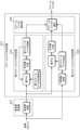
- FIG. 6 is a block diagram showing the configuration of an image encoding device in this embodiment.
- the image encoding device 200 shown in FIG. 6 encodes an image block by block. Each image is composed of a plurality of pixels, and each block is also composed of a plurality of pixels.
- a block may be a randomly accessible area unit called MCU. For example, a 16 ⁇ 8 pixel MCU may be used as a block.
- the image encoding device 200 performs fixed length or variable length compression on each block of the image according to the target code amount.
- pixels of an image are composed of multiple components such as luminance and color difference.
- the image encoding apparatus 200 encodes the block of the image component by component.
- the plurality of components may be two components of luminance and color difference, or may be three components of red, green, and blue corresponding to RGB. Note that the plurality of components may be four components corresponding to RGBA (Red, Green, Blue, Alpha), including three components of red, green, and blue plus transparency (alpha).
- the image encoding device 200 includes a frequency converter 210, a quantization processor 220, an encoder 230, a feature amount acquirer 240, and a target code amount determiner 250.
- the quantization processor 220 includes a quantizer 221 , a quantization table deriver 222 , and a scale factor determiner 223 .
- these components are electrical circuits.
- the feature amount acquisition unit 240 acquires the feature amount of the data of each component in the processing target block for each component that constitutes a pixel.
- the feature amount of the data may correspond to the complexity of the data.
- the feature amount acquisition device 240 may calculate, for each component, the statistical value of the absolute value of the difference between adjacent pixels in the data of the component as the feature amount of the data of the component.
- the statistical value may be a total value or an average value.
- the average value of the absolute difference values between adjacent pixels can also be expressed as activity.
- the feature amount acquisition unit 240 may obtain the feature amount of the data of each component using Hadamard transform. For example, the feature amount acquisition unit 240 may obtain, for each component, the amount of edges obtained by applying Hadamard transform to the data of the component as the feature amount of the data of the component.
- the feature amount acquisition device 240 may acquire, for each component, information indicating the feature amount of the data of the component from a device external to the image encoding device 200.
- the external device may be a device that calculates feature amounts.
- the external device may be an imaging device, and the feature amount may be determined based on imaging conditions.
- an external device may determine the feature amount according to the image type.
- the target code amount determiner 250 determines the target code amount of the data of the component in accordance with the feature amount of the data of the component in the block to be processed. For example, the target code amount determiner 250 increases the target code amount as the feature amount becomes larger.
- the target code amount determiner 250 may determine the target code amount of the data of each component according to the relationship between the feature amount of the data of the component and the feature amount of other components. Specifically, when the feature amount of the first component data is larger than the feature amount of the second component data, the first target code amount of the first component data is changed to the second target code amount of the second component data. It may be larger than .
- the target code amount determiner 250 maintains the total target code amount of the data of the plurality of components in the plurality of blocks at the reference code amount, and adjusts the ratio of the target code amount between the components for each block according to the feature amount. Good too.
- the frequency converter 210 performs frequency conversion on the data of each component in the block to be processed.
- DCT is used for frequency conversion.
- a plurality of pixel values of the component in the processing target block are converted into a plurality of frequency coefficients of the corresponding component in the processing target block.
- the quantization processor 220 quantizes the transformed data of the component in the target block according to the target code amount of the data of the component in the target block. This compresses the data.
- the scale factor determiner 223 determines the scale factor according to the target code amount, the converted data, and the fixed length encoding algorithm so that the data code amount matches the target code amount.
- the target code amount is the target code amount determined for each component as the target code amount of the data of the component according to the feature amount of the data of the component.
- the quantization table deriver 222 derives a quantization table for the data of the component according to the scale factor for the data of the component.
- the quantizer 221 quantizes the transformed data of each component according to the quantization table for the data of the component.
- the quantization width is defined for each frequency level.
- the scale factor affects the quantization width defined for each frequency level in the quantization table. For example, as the scale factor increases, the quantization width also increases. That is, the quantization width may have a monotonically increasing relationship with the scale factor in a narrow or broad sense. Further, the quantization width may be proportional to the scale factor. Note that a scale factor may be used in which the larger the scale factor, the smaller the quantization width.
- the encoder 230 For each component, the encoder 230 encodes the quantized data of the component in the block to be processed into a stream. Huffman codes may be used for encoding.
- the encoder 230 may feed back the code amount of each component's data to the scale factor determiner 223. Then, the scale factor determiner 223 may determine the scale factor for the data of each component again by updating the scale factor for the data of the component according to the code amount of the data of the component. Determination of the scale factor, derivation of the quantization table, quantization and encoding may then be repeated.
- the block to be processed is encoded according to the target code amount.
- the target code amount is the target code amount determined for each component as the target code amount of the data of the component according to the feature amount of the data of the component.
- the compression rate for the data of the component may be used as the target code amount of the data of the component.
- the code amount of each component data in each block of the image is controlled according to the target code amount of the component data in the block.
- the reference target code amount may be set as a register setting value in the image encoding device 200. Then, the target code amount determiner 250 may determine the target code amount by giving a gain or an offset to the reference target code amount according to the feature amount.
- the reference target code amount may be the same for a plurality of components, or may be different for each component. Further, the reference target code amount may correspond to the above-mentioned total target code amount.
- a feature amount of luminance data in the block to be processed and a feature amount of color difference data in the block to be processed are acquired.
- the target code amount of the luminance data and the target code amount of the chrominance data are determined according to the feature amount of the luminance data and the feature amount of the chrominance data, respectively.
- a scale factor for the luminance data and a scale factor for the chrominance data are determined according to the target code amount of the luminance data and the target code amount of the chrominance data, respectively.
- the luminance data and the chrominance data are quantized and encoded according to the scale factor for the luminance data and the scale factor for the chrominance data, respectively. Therefore, the code amount of luminance data and the code amount of color difference data are controlled according to separate variable target code amounts.
- the brightness data may be actively protected.
- the target code amount determiner 250 may determine each target code amount of the luminance data and chrominance data so that the target code amount of the luminance data is larger than the target code amount of the chrominance data.
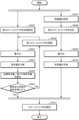
- FIG. 7 is a flowchart showing the operation of the image encoding device 200 shown in FIG. 6.
- an image is divided into a plurality of blocks (S201).
- This division process (S201) may be performed by a divider (not shown) of the image encoding device 200, or may be performed by the frequency converter 210.
- block-by-block loop processing (S202 to S208) is performed.
- the feature amount acquisition unit 240 acquires, for each component, the feature amount of the data of the component in the processing target block (S202).
- the target code amount determiner 250 determines, for each component, the target code amount of the data of the component in the processing target block according to the feature amount of the data of the component in the processing target block (S203).
- the frequency converter 210 performs frequency conversion on the data of each component in the processing target block (S204).
- the quantization processor 220 quantizes the transformed data of the component in the processing target block according to the scale factor (S205). Then, for each component, the encoder 230 encodes the quantized data of the component in the processing target block (S206).
- the processing target block Processing ends. On the other hand, if the generated code amount does not match the target code amount (No in S207), the quantization processor 220 updates the scale factor (S208).
- the quantization processor 220 increases the scale factor to increase the quantization width. If the generated code amount is smaller than the target code amount, the quantization processor 220 reduces the scale factor to reduce the quantization width. Then, quantization (S205), encoding (S206), and updating of the scale factor (S208) are repeated until the generated code amount matches the target code amount.
- FIG. 8A is a conceptual diagram showing an example of calculating the feature amount of brightness data.
- the average value of the absolute difference values between adjacent pixels of the luminance data is calculated as the feature quantity of the luminance data.
- FIG. 8A shows a formula for calculating the average absolute difference value between adjacent pixels of luminance data in a 16 ⁇ 8 pixel MCU in YUV422 format.
- the feature amount acquirer 240 may calculate the average absolute difference value between adjacent pixels of the brightness data as the feature amount of the brightness data according to the formula shown in FIG. 8A.
- act_y in FIG. 8A roughly corresponds, although not strictly, to the average absolute difference value between adjacent pixels of luminance data.
- FIG. 8B is a conceptual diagram showing an example of calculating the feature amount of color difference data.
- the average value of the absolute difference values between adjacent pixels of the color difference data is calculated as the feature amount of the color difference data.
- FIG. 8B shows a formula for calculating the average absolute difference value between adjacent pixels of color difference data in a 16 ⁇ 8 pixel MCU in YUV422 format.
- the feature amount acquisition unit 240 may calculate the average absolute difference value between adjacent pixels of the color difference data as the feature amount of the color difference data according to the formula shown in FIG. 8B.
- Cb(i, j) represents the Cb value of the pixel located at (i, j) in the 8 ⁇ 8 pixels corresponding to Cb
- Cr(i, j) is It represents the Cr value of the pixel located at (i, j) in the 8 ⁇ 8 pixels corresponding to Cr.
- act_c in FIG. 8B roughly corresponds, although not strictly, to the average absolute difference value between adjacent pixels of luminance data.
- FIG. 9 is a conceptual diagram showing the first method for determining the scale factor.
- the scale factor is determined by a search method.
- the frequency converter 210 performs frequency conversion on data in the processing target block of the image.
- the scale factor determiner 223 initializes the scale factor and quantizes the transformed data according to the scale factor. Then, the scale factor determiner 223 obtains a predicted code amount by predicting the code amount according to the quantized data.
- the scale factor determiner 223 updates the scale factor and quantizes the transformed data according to the scale factor again. Then, the scale factor determiner 223 repeats quantization, code amount prediction, and scale factor update until the target code amount matches the predicted code amount, and determines the scale factor.
- FIG. 10 is a flowchart showing the first determination method shown in FIG.
- FIG. 10 shows the operation of the scale factor determiner 223.
- the scale factor determiner 223 initializes the scale factor (S301).
- the scale factor determiner 223 may initialize the scale factor using an average scale factor as an initial value. This suppresses an increase in the number of searches in the search method.
- the scale factor determiner 223 quantizes the transformed data according to the scale factor (S302).
- the quantizer 221 instead of the scale factor determiner 223 may quantize the transformed data according to the scale factor.
- the scale factor determiner 223 obtains a predicted code amount by predicting the code amount according to the quantized data (S303).
- the scale factor determiner 223 may obtain the predicted code amount by applying a Huffman code to the quantized data as the predicted code amount.
- the encoder 230 may encode the quantized data instead of the scale factor determiner 223. Then, the scale factor determiner 223 may predict the code amount by acquiring the code amount from the encoder 230.
- the scale factor determiner 223 calculates the target code amount minus the predicted code amount (S304). Then, the scale factor determiner 223 determines whether the target code amount ⁇ predicted code amount satisfies polarity and convergence conditions (S305). This condition corresponds to the condition that the target code amount and the predicted code amount match.
- the scale factor determiner 223 updates the scale factor according to the polarity and magnitude of the target code amount ⁇ predicted code amount (S306). Then, the scale factor determiner 223 performs quantization (S302), prediction of code amount (S303), calculation of target code amount - predicted code amount (S304), and , the update of the scale factor (S306) is repeated.
- the scale factor determiner 223 determines that the condition is satisfied when the target code amount - predicted code amount is a positive value and is less than or equal to a threshold value.
- the scale factor determiner 223 determines that the target code amount-predicted code amount satisfies the condition. It may be determined that the conditions are satisfied. Alternatively, if the target code amount - predicted code amount is a positive value and the scale factor has been updated a threshold number of times or more, the scale factor determiner 223 determines that the target code amount - predicted code amount satisfies the condition. You may.
- the scale factor determiner 223 may update the scale factor by reducing the amount of change in the scale factor by 1/2 each time the scale factor is updated, until the amount of change in the scale factor reaches the minimum unit. .
- the scale factor determiner 223 may reduce the scale factor. Then, when the target code amount-predicted code amount is a negative value, the scale factor determiner 223 may increase the scale factor. Furthermore, the scale factor determiner 223 may increase the amount of change in the scale factor as the absolute value of the target code amount ⁇ predicted code amount becomes larger.
- the scale factor determiner 223 determines the scale factor at that time as the final scale factor.
- FIG. 11 is a conceptual diagram showing the second method for determining the scale factor.
- the scale factor is initialized according to the feature amount of data in the processing target block of the image.
- the scale factor determiner 223 acquires the feature amount of data in the processing target block of the image, and initializes the scale factor according to the feature amount. The rest is the same as the first determination method.
- FIG. 12 is a flowchart showing the second determination method shown in FIG. 11.
- FIG. 12 shows the operation of the scale factor determiner 223.
- the scale factor determiner 223 acquires the feature amount of the data (S401).
- the scale factor determiner 223 may acquire the feature amount of the data similarly to the feature amount acquirer 240, or may acquire the feature amount of the data from the feature amount acquirer 240.
- the scale factor determiner 223 may acquire the feature amount of the data using a different standard and method than the feature amount obtainer 240.
- the scale factor determiner 223 initializes the scale factor according to the feature amount of the data (S402). For example, the scale factor determiner 223 may initialize the scale factor by using a smaller value as the initial value of the scale factor as the feature amount becomes larger. This suppresses an increase in the number of searches in the search method. Therefore, processing delay is suppressed and throughput performance is improved.
- FIG. 13 is a conceptual diagram showing the third method for determining the scale factor.
- the scale factor finally determined by updating the scale factor is compared with the initial value of the scale factor. Then, if the difference between them is larger than a predetermined threshold value, the initial value of the scale factor corresponding to the feature amount is updated. On the other hand, if the difference is less than or equal to the threshold, the initial value of the scale factor is not updated. This initial value of the scale factor may be used for subsequent blocks with equivalent features.
- the initial value of the scale factor may be updated to the finally determined scale factor value, or an intermediate value (average value) between the initial value before updating and the finally determined scale factor value. may be updated.
- the rest is the same as the second determination method.
- FIG. 14 is a flowchart showing the third determination method shown in FIG. 13. In particular, FIG. 14 shows the operation of the scale factor determiner 223.
- the scale factor determiner 223 performs the same processes (S501 to S507) as the corresponding processes (S401 to S407) in the second determination method until the final determination of the scale factor. After the final determination of the scale factor (Yes in S506), the scale factor determiner 223 compares the final determined scale factor with the initial value of the scale factor, and compares the difference between them with a predetermined threshold ( S508).
- the scale factor determiner 223 updates the initial value of the scale factor corresponding to the feature amount (S509).
- the scale factor determiner 223 does not update the initial value if the difference is less than or equal to a predetermined threshold (No in S508).
- the scale factor determiner 223 does not immediately update the initial value and updates the scale factor to the number of times the difference is determined to be larger than the predetermined threshold.
- the corresponding count value may be counted up.
- the scale factor determiner 223 may update the initial value only when the count value exceeds a threshold value corresponding to a predetermined number of times. Note that the count value may be initialized to 0 at the timing at which image encoding is started, at the timing at which the threshold value is exceeded, or the like.
- the initial value of the scale factor may be updated according to the final scale factor value, similarly to the third determination method.
- FIG. 15 is a conceptual diagram showing the fourth method for determining the scale factor.
- the scale factor determiner 223 includes a first scale factor determiner 310, a second scale factor determiner 320, and a scale factor selector 330.
- these components are electrical circuits.
- the first scale factor determiner 310 determines the first scale factor using the same method as the first determination method of the scale factor. That is, the first scale factor determiner 310 determines the scale factor determined by the first scale factor determining method as the first scale factor. Further, the first scale factor determiner 310 obtains the amount of code predicted according to the first scale factor as the first predicted amount of code.
- the second scale factor determiner 320 determines the second scale factor according to the feature amount of data in the processing target block of the image.
- scale factor determiner 223 quantizes the transformed data according to the second scale factor.
- the scale factor determiner 223 obtains a second predicted code amount by predicting the code amount of the quantized data according to the second scale factor.
- the scale factor selector 330 determines the scale factor by selecting the scale factor from the first scale factor and the second scale factor according to the first predicted code amount and the second predicted code amount.
- FIG. 16 is a flowchart showing the fourth determination method shown in FIG. 15.
- FIG. 16 shows the operations of the first scale factor determiner 310, the second scale factor determiner 320, and the scale factor selector 330 in the scale factor determiner 223.
- the first scale factor determiner 310 performs the same processing (S601 to S606) as the processing (S301 to S306) in the first determination method.
- the scale factor and predicted code amount in the first determination method can be read as the first scale factor and the first predicted code amount.
- the second scale factor determiner 320 acquires the feature amount of the data (S607).
- the second scale factor determiner 320 may acquire the feature amount of the data similarly to the feature amount acquirer 240, or may acquire the feature amount of the data from the feature amount acquirer 240.
- the second scale factor determiner 320 may obtain the feature amount of the data using a different standard and method than the feature amount obtainer 240.
- the second scale factor determiner 320 determines a second scale factor according to the feature amount of the data (S608). For example, the second scale factor determiner 320 may determine a smaller value as the second scale factor as the feature amount becomes larger.
- the second scale factor determiner 320 quantizes the transformed data according to the second scale factor (S609).
- the quantizer 221 instead of the second scale factor determiner 320 may quantize the transformed data according to the second scale factor.
- the second scale factor determiner 320 obtains a second predicted code amount by predicting the code amount according to the quantized data (S610).
- the second scale factor determiner 320 may obtain the code amount predicted by applying a Huffman code to the quantized data as the second predicted code amount.
- the encoder 230 may encode the quantized data instead of the second scale factor determiner 320. Then, the second scale factor determiner 320 may predict the code amount by acquiring the code amount from the encoder 230.
- the scale factor selector 330 determines a scale factor by selecting a scale factor from the first scale factor and the second scale factor according to the first predicted code amount and the second predicted code amount (S611 ).
- the scale factor selector 330 selects the first scale factor and the second predicted code amount is the first predicted code amount. If the second scale factor is more suitable for the target code amount than the second scale factor, the second scale factor is selected.
- the predicted code amount is less than or equal to the target code amount and closer to the target code amount, the more it matches the target code amount.
- a scale factor is selected from the first scale factor based on the search method and the second scale factor based on the feature amount. This prevents the scale factor corresponding to the local solution from being determined as the final scale factor in the search method.
- FIG. 17 is a conceptual diagram showing the fifth method for determining the scale factor.
- the scale factor determiner 223 similarly to the example of the fourth determination method, the scale factor determiner 223 includes a first scale factor determiner 310, a second scale factor determiner 320, and a scale factor selector 330.
- the first scale factor is initialized according to the feature amount of data in the processing target block of the image.
- the first scale factor determiner 310 initializes the first scale factor according to the feature acquired by the second scale factor determiner 320. The rest is the same as the fourth determination method.
- FIG. 18 is a flowchart showing the fifth determination method shown in FIG. 17.
- FIG. 18 particularly shows the operations of the first scale factor determiner 310, second scale factor determiner 320, and scale factor selector 330 in the scale factor determiner 223.
- the second scale factor determiner 320 acquires the feature amount of the data (S701).
- the second scale factor determiner 320 may acquire the feature amount of the data similarly to the feature amount acquirer 240, or may acquire the feature amount of the data from the feature amount acquirer 240.
- the first scale factor determiner 310 initializes the first scale factor according to the feature amount of the data (S702). For example, the first scale factor determiner 310 may initialize the first scale factor by using a smaller value as the initial value of the first scale factor as the feature amount becomes larger. This suppresses an increase in the number of searches in the search method. Therefore, processing delay is suppressed and throughput performance is improved.
- the second scale factor and the second predicted code amount are the same as the initial first scale factor and first predicted code amount in the search method.
- the second scale factor may be interpreted as the initial first scale factor in the search method, and the second predicted code amount may be interpreted as the initial first predicted code amount in the search method. may be done. Then, the process of selecting a scale factor in the fifth determination method is performed from among the initial first scale factor and the final first scale factor according to the initial first predicted code amount and the final first predicted code amount. It may be interpreted as a process of selecting a scale factor.
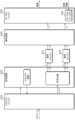
- FIG. 19 is a conceptual diagram showing the first compression example in this embodiment. Similar to the example in FIG. 4, FIG. 19 shows an example of compression of luminance data and color difference data in a 16 ⁇ 8 pixel MCU. Further, the overall compression rate is 25%, and the overall code amount is 512 bits. In other words, the overall compression rate and code amount are the same as in the example of FIG.
- the compression rate of the luminance data (Y) is 37.5%, and the code amount of the luminance data (Y) is 384 bits. Further, the compression rate of the color difference data (Cb and Cr) is 12.5%, and the code amount of the color difference data (Cb and Cr) is 128 bits. That is, the compression rate and code amount of the luminance data (Y) are different from the compression rate and code amount of the color difference data (Cb and Cr).
- the data compression rate and code amount change according to the feature amount of data of each component in the processing target block. For example, for each component, the larger the feature amount of the data of the component in the block to be processed, the larger the target code amount is determined for the data of the component, and the resulting compression ratio and The amount of code is also large.
- the target code amount determiner 250 may change the ratio of the plurality of target code amounts corresponding to the plurality of components depending on the block to be processed, and may maintain the total of the plurality of target code amounts constant regardless of the block to be processed. . Furthermore, the target code amount determiner 250 may set the target code amount for the luminance data to be larger than the target code amount for the chrominance data. Then, the target code amount determiner 250 may determine how much larger the target code amount of the luminance data is to be than the target code amount of the chrominance data, according to the feature amount of the luminance data and the feature amount of the chrominance data.
- the encoder 230 may encode the scale factor and include the encoded scale factor in the stream.
- the image decoding device decodes quantized data and a scale factor from a stream, and performs inverse quantization on the quantized data according to the scale factor. Then, the image decoding device restores the data by performing inverse frequency transform on the inversely quantized data.
- the image encoding device 200 acquires the feature amount for each component and determines the target code amount according to the feature amount. Therefore, the image encoding device 200 can suppress image quality deterioration due to compression of image data. That is, the image encoding device 200 can reduce the code amount of image data while suppressing image deterioration.
- the image encoding device 200 can reduce the memory capacity for storing image data. Furthermore, it becomes possible to reduce the size, cost, and power consumption of devices that handle image data. In addition, pressure on memory bandwidth when accessing image data is alleviated, making it possible to play back moving images with high image quality and high frame rate.
- FIG. 20 is a block diagram showing the configuration of the image processing device in this embodiment.
- the image processing apparatus 400 shown in FIG. Equipped with For example, these components are electrical circuits.
- the image input device 401 acquires an input image.
- the image input device 401 acquires an image input from a camera, an image sensor, or the like.
- Each of the image compressors 402 and 406 corresponds to the image encoding device 200, and encodes the image block by block. At this time, each of the image compressors 402 and 406 compresses data in the block to be processed.
- the memory controller 408 controls access from each component to the memory 409 based on the bus protocol, and controls reading and writing of data to the memory 409.
- the memory 409 is a memory built into the image processing device 400. For example, data after image compression is stored in the memory 409 under the control of the memory controller 408. Further, data after image compression is read from the memory 409 and expanded (decompressed) by image expanders 403 and 407.
- Each of the image decompressors 403 and 407 decodes the image block by block. At this time, each of the image decompressors 403 and 407 decompresses the data in the processing target block.
- the drawing processor 405 renders the image.
- the drawing processor 405 may edit images or generate graphic images.
- the image output device 404 outputs an image.
- the image output device 404 outputs an image to a display device or the like.
- the image output device 404 may output a plurality of images in a superimposed manner.
- FIG. 21 is a block diagram showing the configuration of each of the image compressors 402 and 406 shown in FIG. 20.
- Each of the image compressors 402 and 406 includes a local buffer 510, a preprocessor 520, encoding engines 531 to 534, a postprocessor 540, and a request buffer 550.
- the local buffer 510 also includes a local arbiter 511. For example, these components are electrical circuits.
- the feature amount acquirer 240 and target code amount determiner 250 of the image encoding device 200 may be included in the preprocessor 520. Further, the frequency converter 210 and the quantization processor 220 of the image encoding device 200 may be included in the encoding engines 531 to 534. Furthermore, the encoder 230 of the image encoding device 200 may be included in the encoding engines 531 to 534 and the post-processor 540.
- the encoding engines 531 to 534 correspond to four sequences corresponding to the four components that make up the pixels of the image.
- the four series two series corresponding to luminance and color difference are used.
- encoding engine 533 is used for luminance
- encoding engine 534 is used for chrominance.
- Local arbiter 511 acquires control information and arbitrates access to local buffer 510 according to the control information. Specifically, simultaneous parallel processing of luminance data (Y) and color difference data (C) in the processing target block of the image is controlled.
- the preprocessor 520 obtains luminance data and color difference data from the local buffer 510. Then, the preprocessor 520 obtains the feature amount of the luminance data and the feature amount of the color difference data according to the luminance data and the color difference data. Then, the preprocessor 520 calculates the complexity ratio according to the feature amount of the luminance data and the feature amount of the color difference data.
- the complexity ratio is the ratio of the complexity of luminance data to the complexity of color difference data.
- the preprocessor 520 determines the target code amount for luminance data and the target code amount for chrominance data according to the complexity ratio.
- the preprocessor 520 may derive a target code amount for luminance data and a target code amount for chrominance data from the complexity ratio with reference to a reference table described below.
- the encoding engine 533 acquires the luminance data and the target code amount of the luminance data from the preprocessor 520. Then, the encoding engine 533 performs frequency conversion on the luminance data, quantizes the transformed luminance data according to the target code amount of the luminance data, and encodes the quantized luminance data.
- the encoding engine 534 obtains the color difference data and the target code amount of the color difference data from the preprocessor 520. Then, the encoding engine 534 performs frequency conversion on the color difference data, quantizes the converted color difference data according to the target code amount of the color difference data, and encodes the quantized color difference data.
- the post-processor 540 acquires encoded luminance data from the encoding engine 533 and acquires encoded color difference data from the encoding engine 534. Further, the post-processor 540 obtains the complexity ratio from the pre-processor 520 via the encoding engine 533 or the encoding engine 534. Alternatively, the post-processor 540 may obtain the complexity ratio directly from the pre-processor 520 without going through the encoding engine 533 or the encoding engine 534.
- the post-processor 540 inserts the complexity ratio identification code at the beginning of the encoded color difference data. Then, the post-processor 540 concatenates the encoded color difference data and the encoded luminance data in this order. Thereby, the post-processor 540 packs the complexity ratio identification code, the encoded color difference data, and the encoded luminance data, and generates a stream containing them. That is, the post-processor 540 multiplexes the complexity ratio identification code, encoded color difference data, and encoded luminance data into a stream.
- the post-processor 540 stores the stream in the request buffer 550. Further, the post-processor 540 performs request control on the stream.
- the request buffer 550 stores a stream in which the complexity ratio identification code, encoded color difference data, and encoded luminance data are packed.
- the stream stored in the request buffer 550 is output to the memory 409 or the like.
- the operation performed by the preprocessor 520 may be performed by the feature amount acquirer 240 or the target code amount determiner 250 of the image encoding device 200.
- the operations performed by the encoding engines 531 to 534 may be performed by the frequency converter 210 or the quantization processor 220 of the image encoding device 200.
- the operations performed by the encoding engines 531 to 534 and the post-processor 540 may be performed by the encoder 230 of the image encoding device 200.
- FIG. 22A is a diagram showing a reference table of complexity ratio and target code amount.
- a complexity ratio corresponding to the ratio of the complexity of luminance data to the complexity of color difference data is used. For example, if the ratio of the complexity of luminance data to the complexity of color difference data is less than 1, 0 is used as the complexity ratio.
- the ratio is 1 or more and less than 2, 1 is used as the complexity ratio. If the ratio is 2 or more and less than 3, 2 is used as the complexity ratio. If the ratio is 3 or more and less than 4, 3 is used as the complexity ratio. If the ratio is 4 or more and less than 5, 4 is used as the complexity ratio. When the ratio is greater than or equal to 5 and less than 6, 5 is used as the complexity ratio. If the ratio is 6 or more and less than 7, 6 is used as the complexity ratio. If the ratio is 7 or more, 7 is used as the complexity ratio.
- the target code amount of luminance data and the target code amount of color difference data are associated with the complexity ratio.
- the larger the complexity ratio the larger the target code amount for luminance data, and the smaller the target code amount for chrominance data.
- the total of the target code amount of luminance data and the target code amount of color difference data is constant regardless of the complexity ratio.
- the target code amount for luminance data is larger than the target code amount for chrominance data.
- the amount of uncompressed luminance data and the amount of uncompressed color difference data are each 1024 bits, and a total of 2048 bits.
- the ratio of the target code amount to the uncompressed data amount is shown as the compression ratio.
- only the target code amount expressed by the number of bits for brightness or color difference may be associated with the complexity ratio, or only the compression rate for brightness or color difference may be associated with the target code amount.
- the information may be associated with the complexity ratio.
- FIG. 22B is a graph showing the relationship between complexity ratio and compression ratio.
- the graph in FIG. 22B corresponds to the values shown in FIG. 22A.
- the target code amount for luminance data is larger than the target code amount for chrominance data.
- the greater the relative complexity of the luminance data the greater the difference between the target code amount (compression rate) of the luminance data and the target code amount (compression rate) of the chrominance data.
- FIG. 23 is a flowchart showing the operations of the image compressors 402 and 406 shown in FIGS. 20 and 21.
- the preprocessor 520 sets a reference table in which the complexity ratio between components is associated with the target code amount for each component (S801).
- the preprocessor 520 may set a reference table for each image.
- the preprocessor 520 may set a reference table for each frame forming a moving image.
- the preprocessor 520 acquires the feature amount of the luminance data (S802). Further, in parallel, the preprocessor 520 acquires the feature amount of the color difference data (S803). Then, the preprocessor 520 calculates a complexity ratio, which is a ratio of the complexity of the luminance data to the complexity of the chrominance data, according to the feature amount of the luminance data and the feature amount of the color difference data (S804). Then, the preprocessor 520 determines a target code amount for luminance data and a target code amount for color difference data according to the complexity ratio (S805).
- a complexity ratio which is a ratio of the complexity of the luminance data to the complexity of the chrominance data
- the encoding engine 533 encodes the luminance data according to the target code amount of the luminance data (S806). Specifically, the encoding engine 533 performs frequency conversion on the luminance data, quantizes the transformed luminance data according to the target code amount of the luminance data, and encodes the quantized luminance data.
- the encoding engine 534 encodes the color difference data according to the target code amount of the color difference data (S807). Specifically, the encoding engine 534 performs frequency conversion on the color difference data, quantizes the converted color difference data according to the target code amount of the color difference data, and encodes the quantized color difference data. Then, the post-processor 540 inserts the complexity ratio identification code into the encoded color difference data (S808).
- the post-processor 540 concatenates the encoded color difference data and the encoded luminance data in this order (S809).
- FIG. 24 is a conceptual diagram showing a second compression example in this embodiment. Similar to the example in FIG. 19, FIG. 24 shows an example of compression of luminance data and color difference data in a 16 ⁇ 8 pixel MCU. Further, the overall compression rate is 25%, and the overall code amount is 512 bits. In other words, the overall compression rate and code amount are the same as in the example of FIG.
- a 3-bit identification code is inserted into the color difference data.
- the color difference data is further compressed by 3 bits. For example, 3 bits of data in the high frequency region of the color difference data may be deleted. Then, the luminance data follows the color difference data into which the identification code has been inserted.
- the complexity ratio identification code indicates the target code amount of each of the luminance data and color difference data.
- the identification code can indicate a position corresponding to a break between the luminance data and chrominance data in the stream. Therefore, in this case, it becomes easy to separate each of the luminance data and color difference data from the stream in the decoding process (decompression process).
- the generated code amount may be adjusted to match the target code amount by padding or the like.
- FIG. 25 is a block diagram showing the configuration of each of the image decompressors 403 and 407 shown in FIG. 20.
- Each of the image decompressors 403 and 407 includes a request buffer 610, a preprocessor 620, decoding engines 631 and 632, a postprocessor 640, and a local buffer 650.
- the local buffer 650 also includes a local arbiter 651. For example, these components are electrical circuits.
- the decoding engines 631 and 632 include a decoder, an inverse quantizer, and It consists of an inverse frequency converter, etc.
- the decoder may be, for example, a component that decodes Huffman-encoded stream data according to a target code amount when encoded by the image encoding device 200.
- the dequantizer may be a component that dequantizes the output of the decoder according to the scale factor (header information in the Huffman code) when encoded by the image encoding device 200.
- the inverse frequency converter may use, for example, IDCT (Inverse Discrete Cosine Transform). Thereby, the inverse frequency transformer can perform inverse orthogonal transform on the inversely quantized frequency coefficients to restore pixel data and the like corresponding to each component of the image before encoding.
- decoding engines 631 and 632 for example, use the post-processor 540 shown in FIG. and two series of color difference data. Specifically, decoding engine 631 is used for luminance data, and decoding engine 632 is used for chrominance data. These parallel processes make it possible to shorten the delay time until image output.
- the decoding engine 631 may be used to process the chrominance data and luminance data in series so that the luminance data is processed after the processing of the chrominance data is completed. Note that the processing order of luminance data and color difference data may be reversed. Further, the preprocessor 620 may efficiently allocate each stream to the decoding engines 631 and 632 according to the priority order of each stream output from the request buffer 610 and perform decoding. Note that the decoding engine may be composed of one or more decoding engines. The number of decoding engines may be determined within a range that allows a delay time until image output.
- a stream packed with a complexity ratio identification code, encoded color difference data, and encoded luminance data is transferred from the memory 409 and stored in the request buffer 610.
- the request buffer 610 stores a stream in which data of a plurality of components constituting an image, such as luminance, color difference, red, green, blue, and transparency, are encoded.
- the preprocessor 620 prioritizes the stream of each component necessary to generate the output image based on the control information input to the local buffer 650 and stores it in the request buffer 610. Perform request control.
- the stream stored in the request buffer 610 is input to the preprocessor 620.
- the preprocessor 620 receives a stream packed with a complexity ratio identification code, encoded color difference data, and encoded luminance data.
- the preprocessor 620 determines the target code amount of the luminance data and the target code amount of the chrominance data according to the identification code of the complexity ratio by code separation shown in FIG.
- the target code amount of luminance data and encoded luminance data are input to the decoding engine 631. Further, the target code amount of color difference data and the encoded color difference data are input to the decoding engine 632.
- the preprocessor 620 code separation may derive the target code amount of luminance data and the target code amount of color difference data from the identification code of the complexity ratio by referring to a reference table as shown in FIG. 22A, for example. good. Then, the decoding engines 631 and 632 decode (decompress) the data of each component corresponding to the image before encoding, and input it to the post-processor 640.
- the post-processor 640 converts the data of each component of the expanded image into an arbitrary transfer unit and stores it in the local buffer 650.
- the local buffer 650 receives data for each component of the expanded image as described above.
- the local arbiter 651 acquires control information, arbitrates access to the local buffer 650 according to the control information, and generates and outputs an image to be output for each block.
- FIG. 26 is a diagram showing the image quality evaluation results.
- FIG. 26 shows the average PSNR and worst PSNR of a plurality of blocks in each of 12 types of images in the case where the target code amount is fixed and when the target code amount is variable and determined according to the feature amount. It is shown.
- PSNR is a peak signal-to-noise ratio (Peak Signal-to-Noise Ratio), and the higher the PSNR, the less noise there is.
- the underlined numbers correspond to a PSNR of less than 30 dB.
- the feature amount of luminance data and the feature amount of color difference data differ depending on the type of image and block. Therefore, by determining the target code amount according to the feature amount, extreme deterioration of image quality is suppressed. In particular, by determining the target code amount according to the feature amount, the worst PSNR regarding luminance is improved. Along with this, the worst PSNR regarding color difference deteriorates, but is maintained at 27 dB or more, which is an acceptable level based on human visual characteristics.
- two components luminance and color difference
- three components of red, green, and blue corresponding to RGB may also be used.
- a transparency (alpha) component may be used to blend multiple images.
- the four components red, green, blue and transparency correspond to RGBA. Even in such a case, by determining the target code amount according to the feature amount, significant loss of features can be suppressed.
- the feature amount typically corresponds to the degree of complexity, it may correspond not only to the degree of complexity but also to the size of the feature.
- the image encoding device 200 includes a feature amount acquisition device 240, a target code amount determination device 250, a frequency converter 210, a quantization processor 220, and an encoder 230.
- the feature amount acquisition unit 240 acquires, for each component constituting a pixel of the image, the feature amount of the data of the component in the processing target block among the plurality of blocks of the image. For each component, the target code amount determiner 250 determines the target code amount of the data of the component according to the feature amount of the data of the component.
- the frequency converter 210 performs frequency conversion on the data of each component.
- the quantization processor 220 quantizes the data of each component after frequency conversion according to the target code amount of the data of the component.
- the encoder 230 encodes the quantized data of each component.
- the image encoding device 200 can adjust the target code amount of the data of each component according to the feature amount of the data of the component. Therefore, the image encoding device 200 can suppress significant loss of features. Therefore, the image encoding device 200 can suppress image quality deterioration.
- the plurality of components constituting pixels of an image may include two components: luminance and color difference.
- the image encoding device 200 can adjust the target code amount of the data of each component of luminance and chrominance according to the feature amount of the data of the component. Therefore, the image encoding device 200 can appropriately suppress image quality deterioration for images whose feature amounts differ between luminance and color difference.
- the plurality of components that constitute the pixels of the image may include three components: red, green, and blue.
- the image encoding device 200 can adjust the target code amount of the data of each of the red, green, and blue components according to the feature amount of the data of the component. Therefore, the image encoding device 200 can appropriately suppress image quality deterioration for images with different feature amounts between red, green, and blue.
- the plurality of components that constitute the pixels of the image may include a transparency component.
- the image encoding device can adjust the target code amount of the transparency component (information) when blending multiple images using RGBA, according to the feature amount of the data of the component. . Therefore, the image encoding device 200 can appropriately suppress image quality deterioration when blending a plurality of images. Also. It is possible to suppress the memory capacity required to hold the transparency component and the delay that occurs in transmitting the data.
- the feature amount acquisition unit 240 may obtain, for each component, the statistical value of the absolute value of the difference between adjacent pixels in the data of the component as the feature amount of the data of the component.
- the image encoding device 200 can acquire feature amounts corresponding to steep changes between adjacent pixels. Therefore, the image encoding device 200 can appropriately adjust the target code amount according to the feature amount corresponding to a sudden change between adjacent pixels.
- the feature amount acquisition device 240 may obtain the feature amount of the data of each component using Hadamard transform.
- the image encoding device 200 can acquire feature amounts corresponding to the amount of edges and the like obtained by Hadamard transform. Therefore, the image encoding device 200 can appropriately adjust the target code amount according to the feature amount corresponding to the amount of edges and the like.
- the feature amount acquisition device 240 may acquire, for each component, information indicating the feature amount of data of the component from a device external to the image encoding device 200. Thereby, the feature amount acquisition device 240 may obtain the feature amount of the data of each component. Thereby, the image encoding device 200 can acquire the feature amount without calculating the feature amount. Therefore, image encoding device 200 can reduce calculation processing.
- the encoder 230 may multiplex identification codes indicating a plurality of target code amounts determined for a plurality of components and a plurality of data encoded for a plurality of components into a stream. Encoder 230 may then output the stream. Thereby, the image encoding device 200 can indicate the target code amount of data of each component in the stream. Therefore, the image encoding device 200 can support decoding data of each component from the stream.
- the quantization processor 220 may determine a scale factor that affects the quantization width for each component according to the target code amount. The quantization processor 220 may then quantize the data of each component according to the scale factor.
- the image encoding device 200 can adjust the scale factor used for quantizing the data of each component according to the target code amount of the data of each component. Therefore, the image encoding device 200 can appropriately adjust the code amount of the data of each component according to the target code amount of the data of each component.
- the quantization processor 220 may first initialize the scale factor. The quantization processor 220 may then quantize the data according to the scale factor. Then, the quantization processor 220 may obtain the predicted code amount of the data according to the data quantized according to the scale factor. The quantization processor 220 may then update the scale factor according to the comparison result between the predicted code amount and the target code amount.
- the quantization processor 220 determines the scale factor by repeating data quantization, obtaining the predicted code amount, and updating the scale factor until the predicted code amount matches the target code amount. good.
- the image encoding device 200 can search for and determine a scale factor that makes the predicted code amount match the target code amount. Therefore, the image encoding device 200 can determine an appropriate scale factor for the target code amount.
- the quantization processor 220 may initialize the scale factor according to the feature amount of the data. Thereby, the image encoding device 200 can appropriately initialize the scale factor in the search for the scale factor, and can suppress processing delays.
- the quantization processor 220 updates the initial value of the scale factor. Good too. Then, the quantization processor 220 does not need to update the initial value of the scale factor when the difference is less than or equal to the threshold value. Thereby, the image encoding device 200 can update the initial value of the scale factor determined according to the feature amount based on the final scale factor to the optimal value, thereby suppressing processing delay in subsequent processing. can do.
- the quantization processor 220 increments the count value. Good too. Then, if the difference is less than or equal to the first threshold, the quantization processor 220 does not need to count up the count value.
- the quantization processor 220 may update the initial value of the scale factor when the count value is larger than the second threshold. Then, the quantization processor 220 does not need to update the initial value of the scale factor when the count value is less than or equal to the second threshold.
- the image encoding device 200 can update the initial value of the scale factor determined according to the feature amount at an appropriate update frequency based on the final scale factor, so that it can be processed in subsequent processing. Delays can be suppressed.
- the quantization processor 220 may first initialize the first scale factor. The quantization processor 220 may then quantize the data according to the first scale factor. Then, the quantization processor 220 may obtain the first predicted code amount of the data according to the data quantized according to the first scale factor. The quantization processor 220 may then update the first scale factor according to the comparison result between the first predicted code amount and the target code amount.
- the quantization processor 220 repeats the quantization of the data, the acquisition of the first predicted code amount, and the update of the first scale factor until the first predicted code amount matches the target code amount. 1 scale factor may be determined.
- the quantization processor 220 may determine the second scale factor according to the feature amount of the data. The quantization processor 220 may then quantize the data according to the second scale factor. Then, the quantization processor 220 may obtain the second predicted code amount of the data according to the data quantized according to the second scale factor.
- the quantization processor 220 calculates the first scale factor and the second scale based on the comparison result between the first predicted code amount and the target code amount and the comparison result between the second predicted code amount and the target code amount.
- One of the factors may be determined as the scale factor.
- the image encoding device 200 uses both a method of searching for a scale factor such that the predicted code amount matches the target code amount and a method of determining the scale factor based on the feature amount. can be determined. Therefore, the image encoding device 200 can prevent the scale factor corresponding to the local solution in the search from being determined as the final scale factor.
- the quantization processor 220 may initialize the first scale factor according to the feature amount of the data. Thereby, the image encoding device 200 can appropriately initialize the scale factor in the search for the scale factor, and can suppress processing delays.
- a process executed by a specific component in the embodiment may be executed by another component instead of the specific component.
- the order of the plurality of processes may be changed, or the plurality of processes may be executed in parallel.
- a combination of a plurality of modified examples may be applied.
- the ordinal numbers such as first and second used in the explanation may be replaced, removed, or newly added as appropriate. These ordinal numbers do not necessarily correspond to any meaningful order and may be used to identify elements.
- an image encoding method including steps performed by each component of the image encoding device may be executed by any device or system.
- part or all of the image encoding method may be executed by a computer including a processor, memory, input/output circuits, and the like.
- the image encoding method may be executed by the computer executing a program for causing the computer to execute the image encoding method.
- the above program may be recorded on a non-temporary computer-readable recording medium such as a CD-ROM.
- each component of the image encoding device may be composed of dedicated hardware, general-purpose hardware that executes the above programs, etc., or a combination of these.
- the general-purpose hardware may include a memory in which a program is recorded, a general-purpose processor that reads the program from the memory, and executes the program.
- the memory may be a semiconductor memory or a hard disk, and the general-purpose processor may be a CPU or the like.
- the dedicated hardware may be composed of a memory, a dedicated processor, and the like.
- a dedicated processor may execute the image encoding method described above with reference to a memory for recording data.
- each component of the image encoding device may be an electric circuit.
- These electric circuits may constitute one electric circuit as a whole, or may be separate electric circuits.
- these electric circuits may correspond to dedicated hardware or may correspond to general-purpose hardware that executes the above programs and the like.
- the present disclosure is useful, for example, for an encoding device that encodes an image, and is applicable to a digital camera, a digital video camera, a digital video recorder, an image processing system, and the like.
Landscapes
- Engineering & Computer Science (AREA)
- Multimedia (AREA)
- Signal Processing (AREA)
- Compression Or Coding Systems Of Tv Signals (AREA)
Priority Applications (3)
| Application Number | Priority Date | Filing Date | Title |
|---|---|---|---|
| JP2024517319A JPWO2023210594A1 (https=) | 2022-04-27 | 2023-04-24 | |
| KR1020247034470A KR20250003592A (ko) | 2022-04-27 | 2023-04-24 | 화상 부호화 장치 및 화상 부호화 방법 |
| CN202380035608.5A CN119054278A (zh) | 2022-04-27 | 2023-04-24 | 图像编码装置及图像编码方法 |
Applications Claiming Priority (2)
| Application Number | Priority Date | Filing Date | Title |
|---|---|---|---|
| JP2022073863 | 2022-04-27 | ||
| JP2022-073863 | 2022-04-27 |
Publications (1)
| Publication Number | Publication Date |
|---|---|
| WO2023210594A1 true WO2023210594A1 (ja) | 2023-11-02 |
Family
ID=88518948
Family Applications (1)
| Application Number | Title | Priority Date | Filing Date |
|---|---|---|---|
| PCT/JP2023/016152 Ceased WO2023210594A1 (ja) | 2022-04-27 | 2023-04-24 | 画像符号化装置及び画像符号化方法 |
Country Status (4)
| Country | Link |
|---|---|
| JP (1) | JPWO2023210594A1 (https=) |
| KR (1) | KR20250003592A (https=) |
| CN (1) | CN119054278A (https=) |
| WO (1) | WO2023210594A1 (https=) |
Cited By (1)
| Publication number | Priority date | Publication date | Assignee | Title |
|---|---|---|---|---|
| WO2026075049A1 (ja) * | 2024-10-02 | 2026-04-09 | ヌヴォトンテクノロジージャパン株式会社 | 画像符号化装置及び画像符号化方法 |
Citations (7)
| Publication number | Priority date | Publication date | Assignee | Title |
|---|---|---|---|---|
| JP2006166259A (ja) * | 2004-12-09 | 2006-06-22 | Nikon Corp | デジタルカメラ並びにデジタルカメラシステム、画像圧縮方法、画像処理方法及びプログラム並びにそれらを記録したコンピュータ読み取り可能な記録媒体 |
| JP2009038746A (ja) * | 2007-08-03 | 2009-02-19 | Panasonic Corp | 画像情報符号化装置 |
| JP2009188826A (ja) * | 2008-02-07 | 2009-08-20 | Toshiba Corp | 動画像符号化装置 |
| JP2013135366A (ja) * | 2011-12-27 | 2013-07-08 | Kddi Corp | 動画像送出装置、動画像受信装置、動画像伝送システム、動画像送出方法、動画像受信方法、およびプログラム |
| CN107071516A (zh) * | 2017-04-08 | 2017-08-18 | 腾讯科技(深圳)有限公司 | 一种图片文件处理方法 |
| JP2018137542A (ja) * | 2017-02-20 | 2018-08-30 | キヤノン株式会社 | 符号化装置、符号化方法、及び、プログラム |
| JP2020092327A (ja) * | 2018-12-05 | 2020-06-11 | キヤノン株式会社 | 画像符号化装置、画像符号化方法、およびプログラム |
Family Cites Families (2)
| Publication number | Priority date | Publication date | Assignee | Title |
|---|---|---|---|---|
| JPS4631629Y1 (https=) | 1968-10-19 | 1971-11-01 | ||
| JP6502739B2 (ja) | 2015-04-28 | 2019-04-17 | キヤノン株式会社 | 画像符号化装置、画像処理装置、画像符号化方法 |
-
2023
- 2023-04-24 JP JP2024517319A patent/JPWO2023210594A1/ja active Pending
- 2023-04-24 CN CN202380035608.5A patent/CN119054278A/zh active Pending
- 2023-04-24 WO PCT/JP2023/016152 patent/WO2023210594A1/ja not_active Ceased
- 2023-04-24 KR KR1020247034470A patent/KR20250003592A/ko active Pending
Patent Citations (7)
| Publication number | Priority date | Publication date | Assignee | Title |
|---|---|---|---|---|
| JP2006166259A (ja) * | 2004-12-09 | 2006-06-22 | Nikon Corp | デジタルカメラ並びにデジタルカメラシステム、画像圧縮方法、画像処理方法及びプログラム並びにそれらを記録したコンピュータ読み取り可能な記録媒体 |
| JP2009038746A (ja) * | 2007-08-03 | 2009-02-19 | Panasonic Corp | 画像情報符号化装置 |
| JP2009188826A (ja) * | 2008-02-07 | 2009-08-20 | Toshiba Corp | 動画像符号化装置 |
| JP2013135366A (ja) * | 2011-12-27 | 2013-07-08 | Kddi Corp | 動画像送出装置、動画像受信装置、動画像伝送システム、動画像送出方法、動画像受信方法、およびプログラム |
| JP2018137542A (ja) * | 2017-02-20 | 2018-08-30 | キヤノン株式会社 | 符号化装置、符号化方法、及び、プログラム |
| CN107071516A (zh) * | 2017-04-08 | 2017-08-18 | 腾讯科技(深圳)有限公司 | 一种图片文件处理方法 |
| JP2020092327A (ja) * | 2018-12-05 | 2020-06-11 | キヤノン株式会社 | 画像符号化装置、画像符号化方法、およびプログラム |
Cited By (1)
| Publication number | Priority date | Publication date | Assignee | Title |
|---|---|---|---|---|
| WO2026075049A1 (ja) * | 2024-10-02 | 2026-04-09 | ヌヴォトンテクノロジージャパン株式会社 | 画像符号化装置及び画像符号化方法 |
Also Published As
| Publication number | Publication date |
|---|---|
| KR20250003592A (ko) | 2025-01-07 |
| CN119054278A (zh) | 2024-11-29 |
| JPWO2023210594A1 (https=) | 2023-11-02 |
Similar Documents
| Publication | Publication Date | Title |
|---|---|---|
| US7801383B2 (en) | Embedded scalar quantizers with arbitrary dead-zone ratios | |
| US8031769B2 (en) | Method and device for controlling quantization scales of a video encoding bit stream | |
| US9258568B2 (en) | Quantization method and apparatus in encoding/decoding | |
| US20120128064A1 (en) | Image processing device and method | |
| US20160330468A1 (en) | Image encoding device, image decoding device, encoded stream conversion device, image encoding method, and image decoding method | |
| CN105580368B (zh) | 图像编码装置和方法以及图像解码装置和方法 | |
| JP2016213528A (ja) | 画像符号化装置、画像処理装置、画像符号化方法 | |
| US11991347B2 (en) | Image processing device | |
| JP2003018599A (ja) | 画像符号化装置および方法 | |
| US20250324035A1 (en) | Image encoding device, image encoding method, image decoding device, image decoding method, and non-transitory computer-readable storage medium | |
| US20080193028A1 (en) | Method of high quality digital image compression | |
| US8073053B2 (en) | Image encoding device that encodes an arbitrary number of moving pictures | |
| WO2023210594A1 (ja) | 画像符号化装置及び画像符号化方法 | |
| KR100598093B1 (ko) | 낮은 메모리 대역폭을 갖는 동영상 압축 장치와 그 방법 | |
| US7965768B2 (en) | Video signal encoding apparatus and computer readable medium with quantization control | |
| WO2026075049A1 (ja) | 画像符号化装置及び画像符号化方法 | |
| US9723312B2 (en) | Method and system for random accessible image compression with adaptive quantization | |
| CN119277073A (zh) | 图像编码装置、图像编码方法、图像解码装置和图像解码方法 | |
| KR20150096353A (ko) | 이미지 인코딩 시스템, 디코딩 시스템 및 그 제공방법 | |
| KR100997218B1 (ko) | 영상 역양자화방법 | |
| JP3027605B2 (ja) | 画像処理装置 | |
| KR20030085336A (ko) | 사람의 시각적 특성을 고려한 색상 양자화를 통한 영상부호화 및 복호화 방법 및 장치 | |
| US20070031048A1 (en) | Image processing apparatus and method | |
| KR20040092522A (ko) | 차영상을 사용한 동영상 압축 및 복원 시스템 | |
| KR20080084900A (ko) | 영상 복호화장치 |
Legal Events
| Date | Code | Title | Description |
|---|---|---|---|
| 121 | Ep: the epo has been informed by wipo that ep was designated in this application |
Ref document number: 23796334 Country of ref document: EP Kind code of ref document: A1 |
|
| WWE | Wipo information: entry into national phase |
Ref document number: 202380035608.5 Country of ref document: CN |
|
| WWE | Wipo information: entry into national phase |
Ref document number: 2024517319 Country of ref document: JP |
|
| WWE | Wipo information: entry into national phase |
Ref document number: 202447081011 Country of ref document: IN |
|
| NENP | Non-entry into the national phase |
Ref country code: DE |
|
| 122 | Ep: pct application non-entry in european phase |
Ref document number: 23796334 Country of ref document: EP Kind code of ref document: A1 |