WO2023210594A1 - Image encoding device and image encoding method - Google Patents
Image encoding device and image encoding method Download PDFInfo
- Publication number
- WO2023210594A1 WO2023210594A1 PCT/JP2023/016152 JP2023016152W WO2023210594A1 WO 2023210594 A1 WO2023210594 A1 WO 2023210594A1 JP 2023016152 W JP2023016152 W JP 2023016152W WO 2023210594 A1 WO2023210594 A1 WO 2023210594A1
- Authority
- WO
- WIPO (PCT)
- Prior art keywords
- data
- scale factor
- code amount
- component
- target code
- Prior art date
Links
- 238000000034 method Methods 0.000 title claims description 96
- 238000013139 quantization Methods 0.000 claims abstract description 161
- 238000006243 chemical reaction Methods 0.000 claims abstract description 34
- 238000012545 processing Methods 0.000 claims description 77
- 238000007906 compression Methods 0.000 description 43
- 230000006835 compression Effects 0.000 description 42
- 238000010586 diagram Methods 0.000 description 39
- 230000008569 process Effects 0.000 description 21
- 230000006866 deterioration Effects 0.000 description 18
- 230000008859 change Effects 0.000 description 8
- 230000001934 delay Effects 0.000 description 7
- 241000255925 Diptera Species 0.000 description 5
- 238000004422 calculation algorithm Methods 0.000 description 4
- 230000009466 transformation Effects 0.000 description 4
- 238000004364 calculation method Methods 0.000 description 3
- 230000000694 effects Effects 0.000 description 3
- 238000002156 mixing Methods 0.000 description 3
- 238000009795 derivation Methods 0.000 description 2
- 238000003384 imaging method Methods 0.000 description 2
- 238000013441 quality evaluation Methods 0.000 description 2
- 238000000926 separation method Methods 0.000 description 2
- 230000000007 visual effect Effects 0.000 description 2
- 241000282412 Homo Species 0.000 description 1
- 230000002411 adverse Effects 0.000 description 1
- 230000009286 beneficial effect Effects 0.000 description 1
- 230000005540 biological transmission Effects 0.000 description 1
- 238000007796 conventional method Methods 0.000 description 1
- 238000013144 data compression Methods 0.000 description 1
- 230000006837 decompression Effects 0.000 description 1
- 230000006872 improvement Effects 0.000 description 1
- 239000000463 material Substances 0.000 description 1
- 238000012986 modification Methods 0.000 description 1
- 230000004048 modification Effects 0.000 description 1
- 239000004065 semiconductor Substances 0.000 description 1
- 230000035945 sensitivity Effects 0.000 description 1
- 238000012546 transfer Methods 0.000 description 1
Images


Classifications
-
- H—ELECTRICITY
- H04—ELECTRIC COMMUNICATION TECHNIQUE
- H04N—PICTORIAL COMMUNICATION, e.g. TELEVISION
- H04N19/00—Methods or arrangements for coding, decoding, compressing or decompressing digital video signals
- H04N19/10—Methods or arrangements for coding, decoding, compressing or decompressing digital video signals using adaptive coding
- H04N19/102—Methods or arrangements for coding, decoding, compressing or decompressing digital video signals using adaptive coding characterised by the element, parameter or selection affected or controlled by the adaptive coding
- H04N19/115—Selection of the code volume for a coding unit prior to coding
-
- H—ELECTRICITY
- H04—ELECTRIC COMMUNICATION TECHNIQUE
- H04N—PICTORIAL COMMUNICATION, e.g. TELEVISION
- H04N19/00—Methods or arrangements for coding, decoding, compressing or decompressing digital video signals
- H04N19/10—Methods or arrangements for coding, decoding, compressing or decompressing digital video signals using adaptive coding
- H04N19/102—Methods or arrangements for coding, decoding, compressing or decompressing digital video signals using adaptive coding characterised by the element, parameter or selection affected or controlled by the adaptive coding
- H04N19/124—Quantisation
- H04N19/126—Details of normalisation or weighting functions, e.g. normalisation matrices or variable uniform quantisers
-
- H—ELECTRICITY
- H04—ELECTRIC COMMUNICATION TECHNIQUE
- H04N—PICTORIAL COMMUNICATION, e.g. TELEVISION
- H04N19/00—Methods or arrangements for coding, decoding, compressing or decompressing digital video signals
- H04N19/10—Methods or arrangements for coding, decoding, compressing or decompressing digital video signals using adaptive coding
- H04N19/134—Methods or arrangements for coding, decoding, compressing or decompressing digital video signals using adaptive coding characterised by the element, parameter or criterion affecting or controlling the adaptive coding
- H04N19/136—Incoming video signal characteristics or properties
-
- H—ELECTRICITY
- H04—ELECTRIC COMMUNICATION TECHNIQUE
- H04N—PICTORIAL COMMUNICATION, e.g. TELEVISION
- H04N19/00—Methods or arrangements for coding, decoding, compressing or decompressing digital video signals
- H04N19/10—Methods or arrangements for coding, decoding, compressing or decompressing digital video signals using adaptive coding
- H04N19/169—Methods or arrangements for coding, decoding, compressing or decompressing digital video signals using adaptive coding characterised by the coding unit, i.e. the structural portion or semantic portion of the video signal being the object or the subject of the adaptive coding
- H04N19/17—Methods or arrangements for coding, decoding, compressing or decompressing digital video signals using adaptive coding characterised by the coding unit, i.e. the structural portion or semantic portion of the video signal being the object or the subject of the adaptive coding the unit being an image region, e.g. an object
- H04N19/176—Methods or arrangements for coding, decoding, compressing or decompressing digital video signals using adaptive coding characterised by the coding unit, i.e. the structural portion or semantic portion of the video signal being the object or the subject of the adaptive coding the unit being an image region, e.g. an object the region being a block, e.g. a macroblock
-
- H—ELECTRICITY
- H04—ELECTRIC COMMUNICATION TECHNIQUE
- H04N—PICTORIAL COMMUNICATION, e.g. TELEVISION
- H04N19/00—Methods or arrangements for coding, decoding, compressing or decompressing digital video signals
- H04N19/10—Methods or arrangements for coding, decoding, compressing or decompressing digital video signals using adaptive coding
- H04N19/169—Methods or arrangements for coding, decoding, compressing or decompressing digital video signals using adaptive coding characterised by the coding unit, i.e. the structural portion or semantic portion of the video signal being the object or the subject of the adaptive coding
- H04N19/186—Methods or arrangements for coding, decoding, compressing or decompressing digital video signals using adaptive coding characterised by the coding unit, i.e. the structural portion or semantic portion of the video signal being the object or the subject of the adaptive coding the unit being a colour or a chrominance component
Definitions
- the present disclosure relates to an image encoding device and an image encoding method.
- Patent Document 1 discloses that in order to prevent the code length of a block including a plurality of groups from exceeding a predetermined value, a quantization step and an encoding method are determined for each group, and the determined quantization step and encoding method are It is disclosed that encoded data is generated by performing encoding processing based on the following.
- Patent Document 2 discloses that image data is compressed by either a first compression algorithm with a fixed scale factor or a second compression algorithm with an adjustable scale factor, and the amount of code is within a predetermined range. It is disclosed that determining whether
- the present disclosure provides an image encoding device and an image encoding method that can suppress image quality deterioration.
- An image encoding device has a feature of acquiring, for each of a plurality of components constituting a pixel of an image, a feature amount of data of the component in a processing target block among a plurality of blocks of the image.
- an amount acquisition unit a target code amount determiner that determines a target code amount of the data of the component for each of the plurality of components according to the feature amount of the data of the component; and for each of the plurality of components, a frequency converter that performs frequency conversion on the data of the component; and a quantizer that quantizes, for each of the plurality of components, the data of the component after frequency conversion according to the target code amount of the data of the component.
- an encoder that encodes, for each of the plurality of components, the data of the component after quantization.
- an image encoding method acquires, for each of a plurality of components constituting a pixel of an image, a feature amount of data of the component in a processing target block among a plurality of blocks of the image. for each of the plurality of components, determining a target code amount of the data of the component according to the feature amount of the data of the component; and for each of the plurality of components, determining the target code amount of the data of the component; for each of the plurality of components, quantizing the data of the component after frequency conversion according to the target code amount of the data of the component; for each, encoding the data of that component after quantization.
- the image encoding device and image encoding method according to one aspect of the present disclosure can suppress image quality deterioration.
- FIG. 2 is a block diagram showing the configuration of an image encoding device in a reference example. It is a flowchart which shows the operation of the image encoding device in a reference example.
- FIG. 3 is a diagram showing a standard quantization table used for luminance data.
- FIG. 3 is a diagram showing a standard quantization table used for color difference data.
- FIG. 7 is a conceptual diagram showing an example of compression of luminance data and color difference data in a reference example.
- FIG. 2 is a conceptual diagram showing mosquito noise caused by quantization errors.
- FIG. 1 is a block diagram showing the configuration of an image encoding device in an embodiment. It is a flowchart showing the operation of the image encoding device in the embodiment.
- FIG. 1 is a block diagram showing the configuration of an image encoding device in an embodiment. It is a flowchart showing the operation of the image encoding device in the embodiment.
- FIG. 1 is a block diagram showing the configuration of an image encoding device in an embodiment.
- FIG. 3 is a conceptual diagram showing an example of calculating a feature amount of brightness data.
- FIG. 3 is a conceptual diagram showing an example of calculating feature amounts of color difference data.
- FIG. 3 is a conceptual diagram showing a first method for determining a scale factor.
- 3 is a flowchart showing a first method for determining a scale factor.
- FIG. 7 is a conceptual diagram showing a second method for determining a scale factor. 7 is a flowchart showing a second method for determining a scale factor.
- FIG. 7 is a conceptual diagram showing a third method for determining a scale factor. It is a flowchart which shows the 3rd determination method of a scale factor. It is a conceptual diagram which shows the 4th determination method of a scale factor.
- FIG. 1 is a block diagram showing the configuration of an image processing device in an embodiment.
- FIG. 2 is a block diagram showing the configuration of an image compressor in an embodiment.
- FIG. 3 is a diagram showing a reference table of complexity ratio and target code amount. It is a graph showing the relationship between complexity ratio and compression rate.
- It is a flowchart showing the operation of the image compressor in the embodiment.
- It is a conceptual diagram which shows the 2nd compression example in embodiment.
- FIG. 2 is a block diagram showing the configuration of an image decompressor in an embodiment. It is a figure showing an image quality evaluation result.
- an image encoding device for each of a plurality of components that constitute a pixel of an image, provides a feature amount of data of the component in a processing target block among a plurality of blocks of the image.
- a target code amount determiner that determines, for each of the plurality of components, a target code amount of the data of the component according to the feature amount of the data of the component;
- a frequency converter performs frequency conversion on the data of the component, and for each of the plurality of components, the data of the component after frequency conversion is converted according to the target code amount of the data of the component. It includes a quantization processor that quantizes, and an encoder that encodes the data of the component after quantization for each of the plurality of components.
- the image encoding device can adjust the target code amount of the data of each component according to the feature amount of the data of each component. Therefore, the image encoding device can suppress significant loss of features. Therefore, the image encoding device can suppress image quality deterioration.
- the plurality of components include two components: luminance and color difference.
- the image encoding device can adjust the target code amount of the data of each component of luminance and chrominance according to the feature amount of the data of the component. Therefore, the image encoding device can appropriately suppress image quality deterioration for images with different feature amounts between luminance and color difference.
- the plurality of components include three components: red, green, and blue.
- the image encoding device can adjust the target code amount of the data of each of the red, green, and blue components according to the feature amount of the data of the component. Therefore, the image encoding device can appropriately suppress image quality deterioration for images in which feature amounts differ between red, green, and blue.
- the plurality of components include transparency.
- the image encoding device can suppress the memory capacity required to hold transparency information when blending multiple images using RGBA and the delay that occurs in transmitting the data.
- the feature amount acquisition device obtains, as the feature amount of the data of the component, a statistical value of an absolute value of a difference between adjacent pixels in the data of the component.
- the image encoding device can acquire feature amounts corresponding to steep changes between adjacent pixels. Therefore, the image encoding device can appropriately adjust the target code amount according to the feature amount corresponding to a sudden change between adjacent pixels.
- the feature amount acquisition device obtains the feature amount of the data of each of the plurality of components using Hadamard transformation.
- the image encoding device can acquire the feature amount corresponding to the amount of edges obtained by Hadamard transform. Therefore, the image encoding device can appropriately adjust the target code amount according to the feature amount corresponding to the amount of edges and the like.
- the feature amount acquisition unit acquires, for each of the plurality of components, information indicating the feature amount of the data of the component from a device external to the image encoding device.
- the feature quantity of the data is acquired.
- the image encoding device can acquire the feature amount without calculating the feature amount. Therefore, the image encoding device can reduce calculation processing.
- the encoder multiplexes identification codes indicating a plurality of target code amounts determined for the plurality of components into a stream, and a plurality of data encoded for the plurality of components, and Output a stream.
- the image encoding device can indicate the target code amount of data of each component in the stream. Therefore, the image encoding device can assist in decoding each component's data from the stream.
- the quantization processor determines a scale factor that affects the quantization width for each of the plurality of components according to the target code amount, and quantizes the data of the component according to the scale factor. .
- the image encoding device can adjust the scale factor used for quantizing the data of each component according to the target code amount of the data of each component. Therefore, the image encoding device can appropriately adjust the code amount of the data of each component according to the target code amount of the data of each component.
- the quantization processor initializes the scale factor, quantizes the data according to the scale factor, and obtains a predicted code amount of the data according to the data quantized according to the scale factor. , updating the scale factor according to a comparison result between the predicted code amount and the target code amount, quantizing the data until the predicted code amount matches the target code amount, and obtaining the predicted code amount; Then, the scale factor is determined by repeating the update of the scale factor.
- the image encoding device can search and determine a scale factor that makes the predicted code amount match the target code amount. Therefore, the image encoding device can determine an appropriate scale factor for the target code amount.
- the quantization processor initializes the scale factor according to the feature amount of the data.
- the image encoding device can appropriately initialize the scale factor in the search for the scale factor, and can suppress processing delays.
- the quantization processor may set the initial value of the scale factor to the initial value of the scale factor. and if the difference is less than or equal to the threshold, the initial value of the scale factor is not updated.
- the quantization processor may count the count value when the difference between the scale factor determined by repeatedly updating the scale factor and the initial value of the scale factor is larger than a first threshold value. and if the difference is less than or equal to the first threshold, the count value is not counted up, and if the count value is greater than the second threshold, the initial value of the scale factor is updated and the count value is If it is less than or equal to the second threshold, the initial value of the scale factor is not updated.
- the image encoding device can update the initial value of the scale factor determined according to the feature amount at an appropriate update frequency based on the final scale factor, resulting in processing delay in subsequent processing. can be suppressed.
- the quantization processor initializes a first scale factor, quantizes the data according to the first scale factor, and quantizes the data according to the data quantized according to the first scale factor. obtaining one predicted code amount, updating the first scale factor according to a comparison result between the first predicted code amount and the target code amount, until the first predicted code amount matches the target code amount,
- the first scale factor is determined by repeating the quantization of the data, the acquisition of the first predicted code amount, and the update of the first scale factor, and the second scale factor is determined according to the feature amount of the data.
- quantize the data according to the second scale factor quantize the data according to the second scale factor, obtain a second predicted code amount of the data according to the data quantized according to the second scale factor, and calculate the first predicted code amount and the Determining one of the first scale factor and the second scale factor as the scale factor based on a comparison result with a target code amount and a comparison result between the second predicted code amount and the target code amount. do.
- the image encoding device uses both a method of searching for a scale factor such that the predicted code amount matches the target code amount and a method of determining the scale factor based on the feature amount. can be determined. Therefore, the image encoding device can prevent the scale factor corresponding to the local solution in the search from being determined as the final scale factor.
- the quantization processor initializes the first scale factor according to the feature amount of the data.
- the image encoding device can appropriately initialize the scale factor in the search for the scale factor, and can suppress processing delays.
- a feature amount of data of the component in a processing target block among a plurality of blocks of the image for each of the plurality of components, determining a target code amount of the data of the component according to the feature amount of the data of the component; performing frequency conversion on the data; for each of the plurality of components, quantizing the data of the component after frequency conversion according to the target code amount of the data of the component; for each component, encoding the data of that component after quantization.
- FIG. 1 is a block diagram showing the configuration of an image encoding device in a reference example.
- the image encoding apparatus 100 shown in FIG. 1 encodes an image block by block. Each image is composed of a plurality of pixels, and each block is also composed of a plurality of pixels.
- the block may be a randomly accessible unit of area called an MCU (Minimum Coded Unit). For example, a 16 ⁇ 8 pixel MCU may be used as a block.
- the image encoding device 100 performs fixed length compression on each block of the image according to the target code amount.
- pixels of an image are composed of multiple components such as luminance and color difference.
- the image encoding apparatus 100 encodes the block of the image component by component.
- the image encoding device 100 independently encodes luminance data and color difference data in a block.
- the image encoding device 100 includes a frequency converter 110, a quantization processor 120, and an encoder 130. Further, the quantization processor 120 includes a quantizer 121 , a quantization table deriver 122 , and a scale factor determiner 123 . For example, these components are electrical circuits.
- the frequency converter 110 performs frequency conversion on data of each component constituting a pixel in the processing target block.
- DCT Discrete Cosine Transform
- a plurality of pixel values of the component in the processing target block are converted into a plurality of frequency coefficients of the corresponding component in the processing target block.
- the quantization processor 120 quantizes the transformed data of the component in the processing target block according to the same fixed target code amount for multiple components. This compresses the data.
- the scale factor determiner 123 determines the scale factor according to the target code amount, the converted data, and the fixed length encoding algorithm so that the data code amount matches the target code amount.
- Quantization table deriver 122 derives a quantization table according to the scale factor.
- the quantizer 121 quantizes the converted data according to the quantization table.
- the quantization width is defined for each frequency level.
- the scale factor affects the quantization width defined for each frequency level in the quantization table. For example, as the scale factor increases, the quantization width also increases. That is, the quantization width may have a monotonically increasing relationship with the scale factor in a narrow or broad sense. Further, the quantization width may be proportional to the scale factor. Note that a scale factor may be used in which the larger the scale factor, the smaller the quantization width.
- the encoder 130 For each component, the encoder 130 encodes the quantized data of the component in the block to be processed into a stream. Huffman codes may be used for encoding. Furthermore, the encoder 130 may feed back the code amount to the scale factor determiner 123. The scale factor determiner 123 may then determine the scale factor again by updating the scale factor according to the amount of code. Determination of the scale factor, derivation of the quantization table, quantization and encoding may then be repeated.
- the block to be processed is encoded according to the target code amount.
- the target code amount may be a register setting value set in the image encoding device 100. Specifically, a compression rate such as 50% or 25% may be used as the target code amount.
- the compression ratio is the ratio of the capacity of compressed data to the capacity of uncompressed data.
- the code amount of each component data in each block of an image is controlled according to the same fixed target code amount.
- the code amount of luminance data and the code amount of color difference data are controlled according to the same fixed target code amount.
- a scale factor for luminance data is determined according to a fixed target code amount.
- the luminance data is then quantized and encoded according to a scale factor for the luminance data.
- a scale factor for color difference data is determined according to the same fixed target code amount.
- the color difference data is then quantized and encoded according to a scale factor for the color difference data.
- FIG. 2 is a flowchart showing the operation of the image encoding device 100 shown in FIG. 1.
- an image is divided into a plurality of blocks (S101).
- This division process (S101) may be performed by a divider (not shown) of the image encoding device 100, or may be performed by the frequency converter 110.
- loop processing (S102 to S106) is performed on a block-by-block basis.
- the frequency converter 110 performs frequency conversion on the data of each component in the processing target block (S102).
- the quantization processor 120 quantizes the transformed data of the component in the processing target block according to the scale factor (S103).
- the encoder 130 encodes the quantized data of the component in the processing target block (S104).
- the quantization processor 120 updates the scale factor (S106).
- the quantization processor 120 increases the scale factor. Then, when the generated code amount is smaller than the target code amount, the quantization processor 120 reduces the scale factor. Then, quantization (S103), encoding (S104), and updating of the scale factor (S106) are repeated until the generated code amount matches the target code amount.
- the block to be processed is encoded according to the target code amount. Further, the image encoding device 100 performs quantization (S103), encoding (S104), updating of the scale factor (S106), etc. for each component. On the other hand, the image encoding device 100 controls the generated code amount using the same fixed target code amount for a plurality of components.
- the quantization table deriving unit 122 may derive the quantization table by reflecting the scale factor on the standard quantization table. Further, a standard quantization table may be defined for each component.
- FIG. 3A is a diagram showing a standard quantization table used for luminance data.
- a quantization width is defined for each frequency level.
- the numbers in the quantization table indicate the quantization width.
- the upper left corresponds to low frequencies, and the lower right corresponds to high frequencies.
- the quantization width is basically set to be small for low frequencies and large for high frequencies. This suppresses subjective image quality deterioration and reduces the amount of code.
- FIG. 3B is a diagram showing a standard quantization table used for color difference data. Similar to FIG. 3A, in FIG. 3B, the numbers in the quantization table indicate the quantization width. People have different senses of brightness and color difference. According to the difference in human sensitivity to brightness and color difference, a quantization table different from the standard quantization table for brightness data is defined as the standard quantization table for color difference data. Note that the standard quantization table used for luminance data may also be used for color difference data.
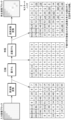
- FIG. 4 is a conceptual diagram showing a compression example in the reference example. Specifically, an example of compression of luminance data and color difference data in a 16 ⁇ 8 pixel MCU is shown.
- the YUV422 format is used, and the 16 x 8 pixel MCU includes a 16 x 8 Y value (luminance value), an 8 x 8 Cb value (blue color difference value), and an 8 x 8 Cr value. Contains the value (red color difference value).
- one Y value, one Cb value, and one Cr value are expressed with 8 bits.
- the same fixed target code amount (compression rate) is used for luminance and color difference. That is, the compression rate is controlled to be the same between the luminance data (Y) and the color difference data (Cb and Cr), and the amount of code is also controlled to be the same.
- the 16 ⁇ 8 Y values in the 16 ⁇ 8 pixel MCU may be divided into two sets each consisting of 8 ⁇ 8 Y values. Then, frequency conversion, quantization, and encoding may be performed in units of 8 ⁇ 8 values. Similarly, frequency conversion, quantization, and encoding may be performed on the 8 ⁇ 8 Cb value and the 8 ⁇ 8 Cr value in units of 8 ⁇ 8 values.
- FIG. 5 is a conceptual diagram showing mosquito noise caused by quantization error.
- image encoding processing and decoding processing frequency conversion, quantization, inverse quantization, and inverse frequency conversion are performed. Specifically, frequency conversion and quantization are performed in image encoding processing, and inverse quantization and inverse frequency conversion are performed in image decoding processing.
- image decoding processing an example is shown in which frequency conversion, quantization, inverse quantization, and inverse frequency conversion are performed on an 8 ⁇ 8 pixel block of an image.
- frequency transformation of blocks of the input image is performed. Specifically, a plurality of pixel values forming a block are decomposed into a plurality of frequency coefficients forming a block according to a plurality of bases of frequency transformation.
- the 8 ⁇ 8 pixel values that make up the block are converted to the 8 ⁇ 8 frequency coefficients that make up the block (bottom left of FIG. 5). Similar to the quantization tables shown in FIGS. 3A and 3B, in the transformed data of the block, the top left corresponds to low frequencies and the bottom right corresponds to high frequencies. For example, if an edge exists in a block of an input image, non-zero frequency coefficients will exist not only in the low frequency region but also in the medium frequency region and the high frequency region.
- each frequency coefficient is quantized according to the corresponding quantization width in the quantization table.
- 8 ⁇ 8 quantized frequency coefficients forming a block are obtained (bottom center of FIG. 5). This compresses the data.
- frequency coefficients are greatly compressed by a large quantization width.
- the quantized data is dequantized. Specifically, each quantized frequency coefficient is dequantized according to the corresponding quantization width in the quantization table. As a result, 8 ⁇ 8 frequency coefficients forming the block are obtained (bottom right of FIG. 5). This expands the data.
- the data of the block after quantization and dequantization is different from the data of the block before quantization and dequantization.
- the data error between these blocks is an error caused by rounding of numerical values due to quantization, and is called a quantization error.
- a quantization error In particular, in a high frequency region, a large quantization width is used, resulting in large quantization errors.
- the inverse frequency transform of the inverse quantized data is performed.
- a plurality of frequency coefficients forming a block are combined into a plurality of pixel values forming a block according to a plurality of bases of frequency transformation.
- 8x8 frequency coefficients that make up a block are converted into 8x8 pixel values that make up the block. In this way, a block of a reproduced image is obtained.
- mosquito noise may occur due to quantization errors, resulting in image quality deterioration.
- mosquito noise is easily recognized visually in flat areas around edges.
- FIG. 6 is a block diagram showing the configuration of an image encoding device in this embodiment.
- the image encoding device 200 shown in FIG. 6 encodes an image block by block. Each image is composed of a plurality of pixels, and each block is also composed of a plurality of pixels.
- a block may be a randomly accessible area unit called MCU. For example, a 16 ⁇ 8 pixel MCU may be used as a block.
- the image encoding device 200 performs fixed length or variable length compression on each block of the image according to the target code amount.
- pixels of an image are composed of multiple components such as luminance and color difference.
- the image encoding apparatus 200 encodes the block of the image component by component.
- the plurality of components may be two components of luminance and color difference, or may be three components of red, green, and blue corresponding to RGB. Note that the plurality of components may be four components corresponding to RGBA (Red, Green, Blue, Alpha), including three components of red, green, and blue plus transparency (alpha).
- the image encoding device 200 includes a frequency converter 210, a quantization processor 220, an encoder 230, a feature amount acquirer 240, and a target code amount determiner 250.
- the quantization processor 220 includes a quantizer 221 , a quantization table deriver 222 , and a scale factor determiner 223 .
- these components are electrical circuits.
- the feature amount acquisition unit 240 acquires the feature amount of the data of each component in the processing target block for each component that constitutes a pixel.
- the feature amount of the data may correspond to the complexity of the data.
- the feature amount acquisition device 240 may calculate, for each component, the statistical value of the absolute value of the difference between adjacent pixels in the data of the component as the feature amount of the data of the component.
- the statistical value may be a total value or an average value.
- the average value of the absolute difference values between adjacent pixels can also be expressed as activity.
- the feature amount acquisition unit 240 may obtain the feature amount of the data of each component using Hadamard transform. For example, the feature amount acquisition unit 240 may obtain, for each component, the amount of edges obtained by applying Hadamard transform to the data of the component as the feature amount of the data of the component.
- the feature amount acquisition device 240 may acquire, for each component, information indicating the feature amount of the data of the component from a device external to the image encoding device 200.
- the external device may be a device that calculates feature amounts.
- the external device may be an imaging device, and the feature amount may be determined based on imaging conditions.
- an external device may determine the feature amount according to the image type.
- the target code amount determiner 250 determines the target code amount of the data of the component in accordance with the feature amount of the data of the component in the block to be processed. For example, the target code amount determiner 250 increases the target code amount as the feature amount becomes larger.
- the target code amount determiner 250 may determine the target code amount of the data of each component according to the relationship between the feature amount of the data of the component and the feature amount of other components. Specifically, when the feature amount of the first component data is larger than the feature amount of the second component data, the first target code amount of the first component data is changed to the second target code amount of the second component data. It may be larger than .
- the target code amount determiner 250 maintains the total target code amount of the data of the plurality of components in the plurality of blocks at the reference code amount, and adjusts the ratio of the target code amount between the components for each block according to the feature amount. Good too.
- the frequency converter 210 performs frequency conversion on the data of each component in the block to be processed.
- DCT is used for frequency conversion.
- a plurality of pixel values of the component in the processing target block are converted into a plurality of frequency coefficients of the corresponding component in the processing target block.
- the quantization processor 220 quantizes the transformed data of the component in the target block according to the target code amount of the data of the component in the target block. This compresses the data.
- the scale factor determiner 223 determines the scale factor according to the target code amount, the converted data, and the fixed length encoding algorithm so that the data code amount matches the target code amount.
- the target code amount is the target code amount determined for each component as the target code amount of the data of the component according to the feature amount of the data of the component.
- the quantization table deriver 222 derives a quantization table for the data of the component according to the scale factor for the data of the component.
- the quantizer 221 quantizes the transformed data of each component according to the quantization table for the data of the component.
- the quantization width is defined for each frequency level.
- the scale factor affects the quantization width defined for each frequency level in the quantization table. For example, as the scale factor increases, the quantization width also increases. That is, the quantization width may have a monotonically increasing relationship with the scale factor in a narrow or broad sense. Further, the quantization width may be proportional to the scale factor. Note that a scale factor may be used in which the larger the scale factor, the smaller the quantization width.
- the encoder 230 For each component, the encoder 230 encodes the quantized data of the component in the block to be processed into a stream. Huffman codes may be used for encoding.
- the encoder 230 may feed back the code amount of each component's data to the scale factor determiner 223. Then, the scale factor determiner 223 may determine the scale factor for the data of each component again by updating the scale factor for the data of the component according to the code amount of the data of the component. Determination of the scale factor, derivation of the quantization table, quantization and encoding may then be repeated.
- the block to be processed is encoded according to the target code amount.
- the target code amount is the target code amount determined for each component as the target code amount of the data of the component according to the feature amount of the data of the component.
- the compression rate for the data of the component may be used as the target code amount of the data of the component.
- the code amount of each component data in each block of the image is controlled according to the target code amount of the component data in the block.
- the reference target code amount may be set as a register setting value in the image encoding device 200. Then, the target code amount determiner 250 may determine the target code amount by giving a gain or an offset to the reference target code amount according to the feature amount.
- the reference target code amount may be the same for a plurality of components, or may be different for each component. Further, the reference target code amount may correspond to the above-mentioned total target code amount.
- a feature amount of luminance data in the block to be processed and a feature amount of color difference data in the block to be processed are acquired.
- the target code amount of the luminance data and the target code amount of the chrominance data are determined according to the feature amount of the luminance data and the feature amount of the chrominance data, respectively.
- a scale factor for the luminance data and a scale factor for the chrominance data are determined according to the target code amount of the luminance data and the target code amount of the chrominance data, respectively.
- the luminance data and the chrominance data are quantized and encoded according to the scale factor for the luminance data and the scale factor for the chrominance data, respectively. Therefore, the code amount of luminance data and the code amount of color difference data are controlled according to separate variable target code amounts.
- the brightness data may be actively protected.
- the target code amount determiner 250 may determine each target code amount of the luminance data and chrominance data so that the target code amount of the luminance data is larger than the target code amount of the chrominance data.
- FIG. 7 is a flowchart showing the operation of the image encoding device 200 shown in FIG. 6.
- an image is divided into a plurality of blocks (S201).
- This division process (S201) may be performed by a divider (not shown) of the image encoding device 200, or may be performed by the frequency converter 210.
- block-by-block loop processing (S202 to S208) is performed.
- the feature amount acquisition unit 240 acquires, for each component, the feature amount of the data of the component in the processing target block (S202).
- the target code amount determiner 250 determines, for each component, the target code amount of the data of the component in the processing target block according to the feature amount of the data of the component in the processing target block (S203).
- the frequency converter 210 performs frequency conversion on the data of each component in the processing target block (S204).
- the quantization processor 220 quantizes the transformed data of the component in the processing target block according to the scale factor (S205). Then, for each component, the encoder 230 encodes the quantized data of the component in the processing target block (S206).
- the processing target block Processing ends. On the other hand, if the generated code amount does not match the target code amount (No in S207), the quantization processor 220 updates the scale factor (S208).
- the quantization processor 220 increases the scale factor to increase the quantization width. If the generated code amount is smaller than the target code amount, the quantization processor 220 reduces the scale factor to reduce the quantization width. Then, quantization (S205), encoding (S206), and updating of the scale factor (S208) are repeated until the generated code amount matches the target code amount.
- FIG. 8A is a conceptual diagram showing an example of calculating the feature amount of brightness data.
- the average value of the absolute difference values between adjacent pixels of the luminance data is calculated as the feature quantity of the luminance data.
- FIG. 8A shows a formula for calculating the average absolute difference value between adjacent pixels of luminance data in a 16 ⁇ 8 pixel MCU in YUV422 format.
- the feature amount acquirer 240 may calculate the average absolute difference value between adjacent pixels of the brightness data as the feature amount of the brightness data according to the formula shown in FIG. 8A.
- act_y in FIG. 8A roughly corresponds, although not strictly, to the average absolute difference value between adjacent pixels of luminance data.
- FIG. 8B is a conceptual diagram showing an example of calculating the feature amount of color difference data.
- the average value of the absolute difference values between adjacent pixels of the color difference data is calculated as the feature amount of the color difference data.
- FIG. 8B shows a formula for calculating the average absolute difference value between adjacent pixels of color difference data in a 16 ⁇ 8 pixel MCU in YUV422 format.
- the feature amount acquisition unit 240 may calculate the average absolute difference value between adjacent pixels of the color difference data as the feature amount of the color difference data according to the formula shown in FIG. 8B.
- Cb(i, j) represents the Cb value of the pixel located at (i, j) in the 8 ⁇ 8 pixels corresponding to Cb
- Cr(i, j) is It represents the Cr value of the pixel located at (i, j) in the 8 ⁇ 8 pixels corresponding to Cr.
- act_c in FIG. 8B roughly corresponds, although not strictly, to the average absolute difference value between adjacent pixels of luminance data.
- FIG. 9 is a conceptual diagram showing the first method for determining the scale factor.
- the scale factor is determined by a search method.
- the frequency converter 210 performs frequency conversion on data in the processing target block of the image.
- the scale factor determiner 223 initializes the scale factor and quantizes the transformed data according to the scale factor. Then, the scale factor determiner 223 obtains a predicted code amount by predicting the code amount according to the quantized data.
- the scale factor determiner 223 updates the scale factor and quantizes the transformed data according to the scale factor again. Then, the scale factor determiner 223 repeats quantization, code amount prediction, and scale factor update until the target code amount matches the predicted code amount, and determines the scale factor.
- FIG. 10 is a flowchart showing the first determination method shown in FIG.
- FIG. 10 shows the operation of the scale factor determiner 223.
- the scale factor determiner 223 initializes the scale factor (S301).
- the scale factor determiner 223 may initialize the scale factor using an average scale factor as an initial value. This suppresses an increase in the number of searches in the search method.
- the scale factor determiner 223 quantizes the transformed data according to the scale factor (S302).
- the quantizer 221 instead of the scale factor determiner 223 may quantize the transformed data according to the scale factor.
- the scale factor determiner 223 obtains a predicted code amount by predicting the code amount according to the quantized data (S303).
- the scale factor determiner 223 may obtain the predicted code amount by applying a Huffman code to the quantized data as the predicted code amount.
- the encoder 230 may encode the quantized data instead of the scale factor determiner 223. Then, the scale factor determiner 223 may predict the code amount by acquiring the code amount from the encoder 230.
- the scale factor determiner 223 calculates the target code amount minus the predicted code amount (S304). Then, the scale factor determiner 223 determines whether the target code amount ⁇ predicted code amount satisfies polarity and convergence conditions (S305). This condition corresponds to the condition that the target code amount and the predicted code amount match.
- the scale factor determiner 223 updates the scale factor according to the polarity and magnitude of the target code amount ⁇ predicted code amount (S306). Then, the scale factor determiner 223 performs quantization (S302), prediction of code amount (S303), calculation of target code amount - predicted code amount (S304), and , the update of the scale factor (S306) is repeated.
- the scale factor determiner 223 determines that the condition is satisfied when the target code amount - predicted code amount is a positive value and is less than or equal to a threshold value.
- the scale factor determiner 223 determines that the target code amount-predicted code amount satisfies the condition. It may be determined that the conditions are satisfied. Alternatively, if the target code amount - predicted code amount is a positive value and the scale factor has been updated a threshold number of times or more, the scale factor determiner 223 determines that the target code amount - predicted code amount satisfies the condition. You may.
- the scale factor determiner 223 may update the scale factor by reducing the amount of change in the scale factor by 1/2 each time the scale factor is updated, until the amount of change in the scale factor reaches the minimum unit. .
- the scale factor determiner 223 may reduce the scale factor. Then, when the target code amount-predicted code amount is a negative value, the scale factor determiner 223 may increase the scale factor. Furthermore, the scale factor determiner 223 may increase the amount of change in the scale factor as the absolute value of the target code amount ⁇ predicted code amount becomes larger.
- the scale factor determiner 223 determines the scale factor at that time as the final scale factor.
- FIG. 11 is a conceptual diagram showing the second method for determining the scale factor.
- the scale factor is initialized according to the feature amount of data in the processing target block of the image.
- the scale factor determiner 223 acquires the feature amount of data in the processing target block of the image, and initializes the scale factor according to the feature amount. The rest is the same as the first determination method.
- FIG. 12 is a flowchart showing the second determination method shown in FIG. 11.
- FIG. 12 shows the operation of the scale factor determiner 223.
- the scale factor determiner 223 acquires the feature amount of the data (S401).
- the scale factor determiner 223 may acquire the feature amount of the data similarly to the feature amount acquirer 240, or may acquire the feature amount of the data from the feature amount acquirer 240.
- the scale factor determiner 223 may acquire the feature amount of the data using a different standard and method than the feature amount obtainer 240.
- the scale factor determiner 223 initializes the scale factor according to the feature amount of the data (S402). For example, the scale factor determiner 223 may initialize the scale factor by using a smaller value as the initial value of the scale factor as the feature amount becomes larger. This suppresses an increase in the number of searches in the search method. Therefore, processing delay is suppressed and throughput performance is improved.
- FIG. 13 is a conceptual diagram showing the third method for determining the scale factor.
- the scale factor finally determined by updating the scale factor is compared with the initial value of the scale factor. Then, if the difference between them is larger than a predetermined threshold value, the initial value of the scale factor corresponding to the feature amount is updated. On the other hand, if the difference is less than or equal to the threshold, the initial value of the scale factor is not updated. This initial value of the scale factor may be used for subsequent blocks with equivalent features.
- the initial value of the scale factor may be updated to the finally determined scale factor value, or an intermediate value (average value) between the initial value before updating and the finally determined scale factor value. may be updated.
- the rest is the same as the second determination method.
- FIG. 14 is a flowchart showing the third determination method shown in FIG. 13. In particular, FIG. 14 shows the operation of the scale factor determiner 223.
- the scale factor determiner 223 performs the same processes (S501 to S507) as the corresponding processes (S401 to S407) in the second determination method until the final determination of the scale factor. After the final determination of the scale factor (Yes in S506), the scale factor determiner 223 compares the final determined scale factor with the initial value of the scale factor, and compares the difference between them with a predetermined threshold ( S508).
- the scale factor determiner 223 updates the initial value of the scale factor corresponding to the feature amount (S509).
- the scale factor determiner 223 does not update the initial value if the difference is less than or equal to a predetermined threshold (No in S508).
- the scale factor determiner 223 does not immediately update the initial value and updates the scale factor to the number of times the difference is determined to be larger than the predetermined threshold.
- the corresponding count value may be counted up.
- the scale factor determiner 223 may update the initial value only when the count value exceeds a threshold value corresponding to a predetermined number of times. Note that the count value may be initialized to 0 at the timing at which image encoding is started, at the timing at which the threshold value is exceeded, or the like.
- the initial value of the scale factor may be updated according to the final scale factor value, similarly to the third determination method.
- FIG. 15 is a conceptual diagram showing the fourth method for determining the scale factor.
- the scale factor determiner 223 includes a first scale factor determiner 310, a second scale factor determiner 320, and a scale factor selector 330.
- these components are electrical circuits.
- the first scale factor determiner 310 determines the first scale factor using the same method as the first determination method of the scale factor. That is, the first scale factor determiner 310 determines the scale factor determined by the first scale factor determining method as the first scale factor. Further, the first scale factor determiner 310 obtains the amount of code predicted according to the first scale factor as the first predicted amount of code.
- the second scale factor determiner 320 determines the second scale factor according to the feature amount of data in the processing target block of the image.
- scale factor determiner 223 quantizes the transformed data according to the second scale factor.
- the scale factor determiner 223 obtains a second predicted code amount by predicting the code amount of the quantized data according to the second scale factor.
- the scale factor selector 330 determines the scale factor by selecting the scale factor from the first scale factor and the second scale factor according to the first predicted code amount and the second predicted code amount.
- FIG. 16 is a flowchart showing the fourth determination method shown in FIG. 15.
- FIG. 16 shows the operations of the first scale factor determiner 310, the second scale factor determiner 320, and the scale factor selector 330 in the scale factor determiner 223.
- the first scale factor determiner 310 performs the same processing (S601 to S606) as the processing (S301 to S306) in the first determination method.
- the scale factor and predicted code amount in the first determination method can be read as the first scale factor and the first predicted code amount.
- the second scale factor determiner 320 acquires the feature amount of the data (S607).
- the second scale factor determiner 320 may acquire the feature amount of the data similarly to the feature amount acquirer 240, or may acquire the feature amount of the data from the feature amount acquirer 240.
- the second scale factor determiner 320 may obtain the feature amount of the data using a different standard and method than the feature amount obtainer 240.
- the second scale factor determiner 320 determines a second scale factor according to the feature amount of the data (S608). For example, the second scale factor determiner 320 may determine a smaller value as the second scale factor as the feature amount becomes larger.
- the second scale factor determiner 320 quantizes the transformed data according to the second scale factor (S609).
- the quantizer 221 instead of the second scale factor determiner 320 may quantize the transformed data according to the second scale factor.
- the second scale factor determiner 320 obtains a second predicted code amount by predicting the code amount according to the quantized data (S610).
- the second scale factor determiner 320 may obtain the code amount predicted by applying a Huffman code to the quantized data as the second predicted code amount.
- the encoder 230 may encode the quantized data instead of the second scale factor determiner 320. Then, the second scale factor determiner 320 may predict the code amount by acquiring the code amount from the encoder 230.
- the scale factor selector 330 determines a scale factor by selecting a scale factor from the first scale factor and the second scale factor according to the first predicted code amount and the second predicted code amount (S611 ).
- the scale factor selector 330 selects the first scale factor and the second predicted code amount is the first predicted code amount. If the second scale factor is more suitable for the target code amount than the second scale factor, the second scale factor is selected.
- the predicted code amount is less than or equal to the target code amount and closer to the target code amount, the more it matches the target code amount.
- a scale factor is selected from the first scale factor based on the search method and the second scale factor based on the feature amount. This prevents the scale factor corresponding to the local solution from being determined as the final scale factor in the search method.
- FIG. 17 is a conceptual diagram showing the fifth method for determining the scale factor.
- the scale factor determiner 223 similarly to the example of the fourth determination method, the scale factor determiner 223 includes a first scale factor determiner 310, a second scale factor determiner 320, and a scale factor selector 330.
- the first scale factor is initialized according to the feature amount of data in the processing target block of the image.
- the first scale factor determiner 310 initializes the first scale factor according to the feature acquired by the second scale factor determiner 320. The rest is the same as the fourth determination method.
- FIG. 18 is a flowchart showing the fifth determination method shown in FIG. 17.
- FIG. 18 particularly shows the operations of the first scale factor determiner 310, second scale factor determiner 320, and scale factor selector 330 in the scale factor determiner 223.
- the second scale factor determiner 320 acquires the feature amount of the data (S701).
- the second scale factor determiner 320 may acquire the feature amount of the data similarly to the feature amount acquirer 240, or may acquire the feature amount of the data from the feature amount acquirer 240.
- the first scale factor determiner 310 initializes the first scale factor according to the feature amount of the data (S702). For example, the first scale factor determiner 310 may initialize the first scale factor by using a smaller value as the initial value of the first scale factor as the feature amount becomes larger. This suppresses an increase in the number of searches in the search method. Therefore, processing delay is suppressed and throughput performance is improved.
- the second scale factor and the second predicted code amount are the same as the initial first scale factor and first predicted code amount in the search method.
- the second scale factor may be interpreted as the initial first scale factor in the search method, and the second predicted code amount may be interpreted as the initial first predicted code amount in the search method. may be done. Then, the process of selecting a scale factor in the fifth determination method is performed from among the initial first scale factor and the final first scale factor according to the initial first predicted code amount and the final first predicted code amount. It may be interpreted as a process of selecting a scale factor.
- FIG. 19 is a conceptual diagram showing the first compression example in this embodiment. Similar to the example in FIG. 4, FIG. 19 shows an example of compression of luminance data and color difference data in a 16 ⁇ 8 pixel MCU. Further, the overall compression rate is 25%, and the overall code amount is 512 bits. In other words, the overall compression rate and code amount are the same as in the example of FIG.
- the compression rate of the luminance data (Y) is 37.5%, and the code amount of the luminance data (Y) is 384 bits. Further, the compression rate of the color difference data (Cb and Cr) is 12.5%, and the code amount of the color difference data (Cb and Cr) is 128 bits. That is, the compression rate and code amount of the luminance data (Y) are different from the compression rate and code amount of the color difference data (Cb and Cr).
- the data compression rate and code amount change according to the feature amount of data of each component in the processing target block. For example, for each component, the larger the feature amount of the data of the component in the block to be processed, the larger the target code amount is determined for the data of the component, and the resulting compression ratio and The amount of code is also large.
- the target code amount determiner 250 may change the ratio of the plurality of target code amounts corresponding to the plurality of components depending on the block to be processed, and may maintain the total of the plurality of target code amounts constant regardless of the block to be processed. . Furthermore, the target code amount determiner 250 may set the target code amount for the luminance data to be larger than the target code amount for the chrominance data. Then, the target code amount determiner 250 may determine how much larger the target code amount of the luminance data is to be than the target code amount of the chrominance data, according to the feature amount of the luminance data and the feature amount of the chrominance data.
- the encoder 230 may encode the scale factor and include the encoded scale factor in the stream.
- the image decoding device decodes quantized data and a scale factor from a stream, and performs inverse quantization on the quantized data according to the scale factor. Then, the image decoding device restores the data by performing inverse frequency transform on the inversely quantized data.
- the image encoding device 200 acquires the feature amount for each component and determines the target code amount according to the feature amount. Therefore, the image encoding device 200 can suppress image quality deterioration due to compression of image data. That is, the image encoding device 200 can reduce the code amount of image data while suppressing image deterioration.
- the image encoding device 200 can reduce the memory capacity for storing image data. Furthermore, it becomes possible to reduce the size, cost, and power consumption of devices that handle image data. In addition, pressure on memory bandwidth when accessing image data is alleviated, making it possible to play back moving images with high image quality and high frame rate.
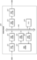
- FIG. 20 is a block diagram showing the configuration of the image processing device in this embodiment.
- the image processing apparatus 400 shown in FIG. Equipped with For example, these components are electrical circuits.
- the image input device 401 acquires an input image.
- the image input device 401 acquires an image input from a camera, an image sensor, or the like.
- Each of the image compressors 402 and 406 corresponds to the image encoding device 200, and encodes the image block by block. At this time, each of the image compressors 402 and 406 compresses data in the block to be processed.
- the memory controller 408 controls access from each component to the memory 409 based on the bus protocol, and controls reading and writing of data to the memory 409.
- the memory 409 is a memory built into the image processing device 400. For example, data after image compression is stored in the memory 409 under the control of the memory controller 408. Further, data after image compression is read from the memory 409 and expanded (decompressed) by image expanders 403 and 407.
- Each of the image decompressors 403 and 407 decodes the image block by block. At this time, each of the image decompressors 403 and 407 decompresses the data in the processing target block.
- the drawing processor 405 renders the image.
- the drawing processor 405 may edit images or generate graphic images.
- the image output device 404 outputs an image.
- the image output device 404 outputs an image to a display device or the like.
- the image output device 404 may output a plurality of images in a superimposed manner.
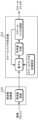
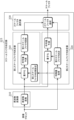
- FIG. 21 is a block diagram showing the configuration of each of the image compressors 402 and 406 shown in FIG. 20.
- Each of the image compressors 402 and 406 includes a local buffer 510, a preprocessor 520, encoding engines 531 to 534, a postprocessor 540, and a request buffer 550.
- the local buffer 510 also includes a local arbiter 511. For example, these components are electrical circuits.
- the feature amount acquirer 240 and target code amount determiner 250 of the image encoding device 200 may be included in the preprocessor 520. Further, the frequency converter 210 and the quantization processor 220 of the image encoding device 200 may be included in the encoding engines 531 to 534. Furthermore, the encoder 230 of the image encoding device 200 may be included in the encoding engines 531 to 534 and the post-processor 540.
- the encoding engines 531 to 534 correspond to four sequences corresponding to the four components that make up the pixels of the image.
- the four series two series corresponding to luminance and color difference are used.
- encoding engine 533 is used for luminance
- encoding engine 534 is used for chrominance.
- Local arbiter 511 acquires control information and arbitrates access to local buffer 510 according to the control information. Specifically, simultaneous parallel processing of luminance data (Y) and color difference data (C) in the processing target block of the image is controlled.
- the preprocessor 520 obtains luminance data and color difference data from the local buffer 510. Then, the preprocessor 520 obtains the feature amount of the luminance data and the feature amount of the color difference data according to the luminance data and the color difference data. Then, the preprocessor 520 calculates the complexity ratio according to the feature amount of the luminance data and the feature amount of the color difference data.
- the complexity ratio is the ratio of the complexity of luminance data to the complexity of color difference data.
- the preprocessor 520 determines the target code amount for luminance data and the target code amount for chrominance data according to the complexity ratio.
- the preprocessor 520 may derive a target code amount for luminance data and a target code amount for chrominance data from the complexity ratio with reference to a reference table described below.
- the encoding engine 533 acquires the luminance data and the target code amount of the luminance data from the preprocessor 520. Then, the encoding engine 533 performs frequency conversion on the luminance data, quantizes the transformed luminance data according to the target code amount of the luminance data, and encodes the quantized luminance data.
- the encoding engine 534 obtains the color difference data and the target code amount of the color difference data from the preprocessor 520. Then, the encoding engine 534 performs frequency conversion on the color difference data, quantizes the converted color difference data according to the target code amount of the color difference data, and encodes the quantized color difference data.
- the post-processor 540 acquires encoded luminance data from the encoding engine 533 and acquires encoded color difference data from the encoding engine 534. Further, the post-processor 540 obtains the complexity ratio from the pre-processor 520 via the encoding engine 533 or the encoding engine 534. Alternatively, the post-processor 540 may obtain the complexity ratio directly from the pre-processor 520 without going through the encoding engine 533 or the encoding engine 534.
- the post-processor 540 inserts the complexity ratio identification code at the beginning of the encoded color difference data. Then, the post-processor 540 concatenates the encoded color difference data and the encoded luminance data in this order. Thereby, the post-processor 540 packs the complexity ratio identification code, the encoded color difference data, and the encoded luminance data, and generates a stream containing them. That is, the post-processor 540 multiplexes the complexity ratio identification code, encoded color difference data, and encoded luminance data into a stream.
- the post-processor 540 stores the stream in the request buffer 550. Further, the post-processor 540 performs request control on the stream.
- the request buffer 550 stores a stream in which the complexity ratio identification code, encoded color difference data, and encoded luminance data are packed.
- the stream stored in the request buffer 550 is output to the memory 409 or the like.
- the operation performed by the preprocessor 520 may be performed by the feature amount acquirer 240 or the target code amount determiner 250 of the image encoding device 200.
- the operations performed by the encoding engines 531 to 534 may be performed by the frequency converter 210 or the quantization processor 220 of the image encoding device 200.
- the operations performed by the encoding engines 531 to 534 and the post-processor 540 may be performed by the encoder 230 of the image encoding device 200.
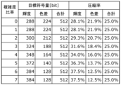
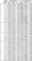
- FIG. 22A is a diagram showing a reference table of complexity ratio and target code amount.
- a complexity ratio corresponding to the ratio of the complexity of luminance data to the complexity of color difference data is used. For example, if the ratio of the complexity of luminance data to the complexity of color difference data is less than 1, 0 is used as the complexity ratio.
- the ratio is 1 or more and less than 2, 1 is used as the complexity ratio. If the ratio is 2 or more and less than 3, 2 is used as the complexity ratio. If the ratio is 3 or more and less than 4, 3 is used as the complexity ratio. If the ratio is 4 or more and less than 5, 4 is used as the complexity ratio. When the ratio is greater than or equal to 5 and less than 6, 5 is used as the complexity ratio. If the ratio is 6 or more and less than 7, 6 is used as the complexity ratio. If the ratio is 7 or more, 7 is used as the complexity ratio.
- the target code amount of luminance data and the target code amount of color difference data are associated with the complexity ratio.
- the larger the complexity ratio the larger the target code amount for luminance data, and the smaller the target code amount for chrominance data.
- the total of the target code amount of luminance data and the target code amount of color difference data is constant regardless of the complexity ratio.
- the target code amount for luminance data is larger than the target code amount for chrominance data.
- the amount of uncompressed luminance data and the amount of uncompressed color difference data are each 1024 bits, and a total of 2048 bits.
- the ratio of the target code amount to the uncompressed data amount is shown as the compression ratio.
- only the target code amount expressed by the number of bits for brightness or color difference may be associated with the complexity ratio, or only the compression rate for brightness or color difference may be associated with the target code amount.
- the information may be associated with the complexity ratio.
- FIG. 22B is a graph showing the relationship between complexity ratio and compression ratio.
- the graph in FIG. 22B corresponds to the values shown in FIG. 22A.
- the target code amount for luminance data is larger than the target code amount for chrominance data.
- the greater the relative complexity of the luminance data the greater the difference between the target code amount (compression rate) of the luminance data and the target code amount (compression rate) of the chrominance data.
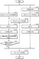
- FIG. 23 is a flowchart showing the operations of the image compressors 402 and 406 shown in FIGS. 20 and 21.
- the preprocessor 520 sets a reference table in which the complexity ratio between components is associated with the target code amount for each component (S801).
- the preprocessor 520 may set a reference table for each image.
- the preprocessor 520 may set a reference table for each frame forming a moving image.
- the preprocessor 520 acquires the feature amount of the luminance data (S802). Further, in parallel, the preprocessor 520 acquires the feature amount of the color difference data (S803). Then, the preprocessor 520 calculates a complexity ratio, which is a ratio of the complexity of the luminance data to the complexity of the chrominance data, according to the feature amount of the luminance data and the feature amount of the color difference data (S804). Then, the preprocessor 520 determines a target code amount for luminance data and a target code amount for color difference data according to the complexity ratio (S805).
- a complexity ratio which is a ratio of the complexity of the luminance data to the complexity of the chrominance data
- the encoding engine 533 encodes the luminance data according to the target code amount of the luminance data (S806). Specifically, the encoding engine 533 performs frequency conversion on the luminance data, quantizes the transformed luminance data according to the target code amount of the luminance data, and encodes the quantized luminance data.
- the encoding engine 534 encodes the color difference data according to the target code amount of the color difference data (S807). Specifically, the encoding engine 534 performs frequency conversion on the color difference data, quantizes the converted color difference data according to the target code amount of the color difference data, and encodes the quantized color difference data. Then, the post-processor 540 inserts the complexity ratio identification code into the encoded color difference data (S808).
- the post-processor 540 concatenates the encoded color difference data and the encoded luminance data in this order (S809).
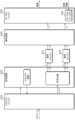
- FIG. 24 is a conceptual diagram showing a second compression example in this embodiment. Similar to the example in FIG. 19, FIG. 24 shows an example of compression of luminance data and color difference data in a 16 ⁇ 8 pixel MCU. Further, the overall compression rate is 25%, and the overall code amount is 512 bits. In other words, the overall compression rate and code amount are the same as in the example of FIG.
- a 3-bit identification code is inserted into the color difference data.
- the color difference data is further compressed by 3 bits. For example, 3 bits of data in the high frequency region of the color difference data may be deleted. Then, the luminance data follows the color difference data into which the identification code has been inserted.
- the complexity ratio identification code indicates the target code amount of each of the luminance data and color difference data.
- the identification code can indicate a position corresponding to a break between the luminance data and chrominance data in the stream. Therefore, in this case, it becomes easy to separate each of the luminance data and color difference data from the stream in the decoding process (decompression process).
- the generated code amount may be adjusted to match the target code amount by padding or the like.
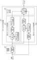
- FIG. 25 is a block diagram showing the configuration of each of the image decompressors 403 and 407 shown in FIG. 20.
- Each of the image decompressors 403 and 407 includes a request buffer 610, a preprocessor 620, decoding engines 631 and 632, a postprocessor 640, and a local buffer 650.
- the local buffer 650 also includes a local arbiter 651. For example, these components are electrical circuits.
- the decoding engines 631 and 632 include a decoder, an inverse quantizer, and It consists of an inverse frequency converter, etc.
- the decoder may be, for example, a component that decodes Huffman-encoded stream data according to a target code amount when encoded by the image encoding device 200.
- the dequantizer may be a component that dequantizes the output of the decoder according to the scale factor (header information in the Huffman code) when encoded by the image encoding device 200.
- the inverse frequency converter may use, for example, IDCT (Inverse Discrete Cosine Transform). Thereby, the inverse frequency transformer can perform inverse orthogonal transform on the inversely quantized frequency coefficients to restore pixel data and the like corresponding to each component of the image before encoding.
- decoding engines 631 and 632 for example, use the post-processor 540 shown in FIG. and two series of color difference data. Specifically, decoding engine 631 is used for luminance data, and decoding engine 632 is used for chrominance data. These parallel processes make it possible to shorten the delay time until image output.
- the decoding engine 631 may be used to process the chrominance data and luminance data in series so that the luminance data is processed after the processing of the chrominance data is completed. Note that the processing order of luminance data and color difference data may be reversed. Further, the preprocessor 620 may efficiently allocate each stream to the decoding engines 631 and 632 according to the priority order of each stream output from the request buffer 610 and perform decoding. Note that the decoding engine may be composed of one or more decoding engines. The number of decoding engines may be determined within a range that allows a delay time until image output.
- a stream packed with a complexity ratio identification code, encoded color difference data, and encoded luminance data is transferred from the memory 409 and stored in the request buffer 610.
- the request buffer 610 stores a stream in which data of a plurality of components constituting an image, such as luminance, color difference, red, green, blue, and transparency, are encoded.
- the preprocessor 620 prioritizes the stream of each component necessary to generate the output image based on the control information input to the local buffer 650 and stores it in the request buffer 610. Perform request control.
- the stream stored in the request buffer 610 is input to the preprocessor 620.
- the preprocessor 620 receives a stream packed with a complexity ratio identification code, encoded color difference data, and encoded luminance data.
- the preprocessor 620 determines the target code amount of the luminance data and the target code amount of the chrominance data according to the identification code of the complexity ratio by code separation shown in FIG.
- the target code amount of luminance data and encoded luminance data are input to the decoding engine 631. Further, the target code amount of color difference data and the encoded color difference data are input to the decoding engine 632.
- the preprocessor 620 code separation may derive the target code amount of luminance data and the target code amount of color difference data from the identification code of the complexity ratio by referring to a reference table as shown in FIG. 22A, for example. good. Then, the decoding engines 631 and 632 decode (decompress) the data of each component corresponding to the image before encoding, and input it to the post-processor 640.
- the post-processor 640 converts the data of each component of the expanded image into an arbitrary transfer unit and stores it in the local buffer 650.
- the local buffer 650 receives data for each component of the expanded image as described above.
- the local arbiter 651 acquires control information, arbitrates access to the local buffer 650 according to the control information, and generates and outputs an image to be output for each block.
- FIG. 26 is a diagram showing the image quality evaluation results.
- FIG. 26 shows the average PSNR and worst PSNR of a plurality of blocks in each of 12 types of images in the case where the target code amount is fixed and when the target code amount is variable and determined according to the feature amount. It is shown.
- PSNR is a peak signal-to-noise ratio (Peak Signal-to-Noise Ratio), and the higher the PSNR, the less noise there is.
- the underlined numbers correspond to a PSNR of less than 30 dB.
- the feature amount of luminance data and the feature amount of color difference data differ depending on the type of image and block. Therefore, by determining the target code amount according to the feature amount, extreme deterioration of image quality is suppressed. In particular, by determining the target code amount according to the feature amount, the worst PSNR regarding luminance is improved. Along with this, the worst PSNR regarding color difference deteriorates, but is maintained at 27 dB or more, which is an acceptable level based on human visual characteristics.
- two components luminance and color difference
- three components of red, green, and blue corresponding to RGB may also be used.
- a transparency (alpha) component may be used to blend multiple images.
- the four components red, green, blue and transparency correspond to RGBA. Even in such a case, by determining the target code amount according to the feature amount, significant loss of features can be suppressed.
- the feature amount typically corresponds to the degree of complexity, it may correspond not only to the degree of complexity but also to the size of the feature.
- the image encoding device 200 includes a feature amount acquisition device 240, a target code amount determination device 250, a frequency converter 210, a quantization processor 220, and an encoder 230.
- the feature amount acquisition unit 240 acquires, for each component constituting a pixel of the image, the feature amount of the data of the component in the processing target block among the plurality of blocks of the image. For each component, the target code amount determiner 250 determines the target code amount of the data of the component according to the feature amount of the data of the component.
- the frequency converter 210 performs frequency conversion on the data of each component.
- the quantization processor 220 quantizes the data of each component after frequency conversion according to the target code amount of the data of the component.
- the encoder 230 encodes the quantized data of each component.
- the image encoding device 200 can adjust the target code amount of the data of each component according to the feature amount of the data of the component. Therefore, the image encoding device 200 can suppress significant loss of features. Therefore, the image encoding device 200 can suppress image quality deterioration.
- the plurality of components constituting pixels of an image may include two components: luminance and color difference.
- the image encoding device 200 can adjust the target code amount of the data of each component of luminance and chrominance according to the feature amount of the data of the component. Therefore, the image encoding device 200 can appropriately suppress image quality deterioration for images whose feature amounts differ between luminance and color difference.
- the plurality of components that constitute the pixels of the image may include three components: red, green, and blue.
- the image encoding device 200 can adjust the target code amount of the data of each of the red, green, and blue components according to the feature amount of the data of the component. Therefore, the image encoding device 200 can appropriately suppress image quality deterioration for images with different feature amounts between red, green, and blue.
- the plurality of components that constitute the pixels of the image may include a transparency component.
- the image encoding device can adjust the target code amount of the transparency component (information) when blending multiple images using RGBA, according to the feature amount of the data of the component. . Therefore, the image encoding device 200 can appropriately suppress image quality deterioration when blending a plurality of images. Also. It is possible to suppress the memory capacity required to hold the transparency component and the delay that occurs in transmitting the data.
- the feature amount acquisition unit 240 may obtain, for each component, the statistical value of the absolute value of the difference between adjacent pixels in the data of the component as the feature amount of the data of the component.
- the image encoding device 200 can acquire feature amounts corresponding to steep changes between adjacent pixels. Therefore, the image encoding device 200 can appropriately adjust the target code amount according to the feature amount corresponding to a sudden change between adjacent pixels.
- the feature amount acquisition device 240 may obtain the feature amount of the data of each component using Hadamard transform.
- the image encoding device 200 can acquire feature amounts corresponding to the amount of edges and the like obtained by Hadamard transform. Therefore, the image encoding device 200 can appropriately adjust the target code amount according to the feature amount corresponding to the amount of edges and the like.
- the feature amount acquisition device 240 may acquire, for each component, information indicating the feature amount of data of the component from a device external to the image encoding device 200. Thereby, the feature amount acquisition device 240 may obtain the feature amount of the data of each component. Thereby, the image encoding device 200 can acquire the feature amount without calculating the feature amount. Therefore, image encoding device 200 can reduce calculation processing.
- the encoder 230 may multiplex identification codes indicating a plurality of target code amounts determined for a plurality of components and a plurality of data encoded for a plurality of components into a stream. Encoder 230 may then output the stream. Thereby, the image encoding device 200 can indicate the target code amount of data of each component in the stream. Therefore, the image encoding device 200 can support decoding data of each component from the stream.
- the quantization processor 220 may determine a scale factor that affects the quantization width for each component according to the target code amount. The quantization processor 220 may then quantize the data of each component according to the scale factor.
- the image encoding device 200 can adjust the scale factor used for quantizing the data of each component according to the target code amount of the data of each component. Therefore, the image encoding device 200 can appropriately adjust the code amount of the data of each component according to the target code amount of the data of each component.
- the quantization processor 220 may first initialize the scale factor. The quantization processor 220 may then quantize the data according to the scale factor. Then, the quantization processor 220 may obtain the predicted code amount of the data according to the data quantized according to the scale factor. The quantization processor 220 may then update the scale factor according to the comparison result between the predicted code amount and the target code amount.
- the quantization processor 220 determines the scale factor by repeating data quantization, obtaining the predicted code amount, and updating the scale factor until the predicted code amount matches the target code amount. good.
- the image encoding device 200 can search for and determine a scale factor that makes the predicted code amount match the target code amount. Therefore, the image encoding device 200 can determine an appropriate scale factor for the target code amount.
- the quantization processor 220 may initialize the scale factor according to the feature amount of the data. Thereby, the image encoding device 200 can appropriately initialize the scale factor in the search for the scale factor, and can suppress processing delays.
- the quantization processor 220 updates the initial value of the scale factor. Good too. Then, the quantization processor 220 does not need to update the initial value of the scale factor when the difference is less than or equal to the threshold value. Thereby, the image encoding device 200 can update the initial value of the scale factor determined according to the feature amount based on the final scale factor to the optimal value, thereby suppressing processing delay in subsequent processing. can do.
- the quantization processor 220 increments the count value. Good too. Then, if the difference is less than or equal to the first threshold, the quantization processor 220 does not need to count up the count value.
- the quantization processor 220 may update the initial value of the scale factor when the count value is larger than the second threshold. Then, the quantization processor 220 does not need to update the initial value of the scale factor when the count value is less than or equal to the second threshold.
- the image encoding device 200 can update the initial value of the scale factor determined according to the feature amount at an appropriate update frequency based on the final scale factor, so that it can be processed in subsequent processing. Delays can be suppressed.
- the quantization processor 220 may first initialize the first scale factor. The quantization processor 220 may then quantize the data according to the first scale factor. Then, the quantization processor 220 may obtain the first predicted code amount of the data according to the data quantized according to the first scale factor. The quantization processor 220 may then update the first scale factor according to the comparison result between the first predicted code amount and the target code amount.
- the quantization processor 220 repeats the quantization of the data, the acquisition of the first predicted code amount, and the update of the first scale factor until the first predicted code amount matches the target code amount. 1 scale factor may be determined.
- the quantization processor 220 may determine the second scale factor according to the feature amount of the data. The quantization processor 220 may then quantize the data according to the second scale factor. Then, the quantization processor 220 may obtain the second predicted code amount of the data according to the data quantized according to the second scale factor.
- the quantization processor 220 calculates the first scale factor and the second scale based on the comparison result between the first predicted code amount and the target code amount and the comparison result between the second predicted code amount and the target code amount.
- One of the factors may be determined as the scale factor.
- the image encoding device 200 uses both a method of searching for a scale factor such that the predicted code amount matches the target code amount and a method of determining the scale factor based on the feature amount. can be determined. Therefore, the image encoding device 200 can prevent the scale factor corresponding to the local solution in the search from being determined as the final scale factor.
- the quantization processor 220 may initialize the first scale factor according to the feature amount of the data. Thereby, the image encoding device 200 can appropriately initialize the scale factor in the search for the scale factor, and can suppress processing delays.
- a process executed by a specific component in the embodiment may be executed by another component instead of the specific component.
- the order of the plurality of processes may be changed, or the plurality of processes may be executed in parallel.
- a combination of a plurality of modified examples may be applied.
- the ordinal numbers such as first and second used in the explanation may be replaced, removed, or newly added as appropriate. These ordinal numbers do not necessarily correspond to any meaningful order and may be used to identify elements.
- an image encoding method including steps performed by each component of the image encoding device may be executed by any device or system.
- part or all of the image encoding method may be executed by a computer including a processor, memory, input/output circuits, and the like.
- the image encoding method may be executed by the computer executing a program for causing the computer to execute the image encoding method.
- the above program may be recorded on a non-temporary computer-readable recording medium such as a CD-ROM.
- each component of the image encoding device may be composed of dedicated hardware, general-purpose hardware that executes the above programs, etc., or a combination of these.
- the general-purpose hardware may include a memory in which a program is recorded, a general-purpose processor that reads the program from the memory, and executes the program.
- the memory may be a semiconductor memory or a hard disk, and the general-purpose processor may be a CPU or the like.
- the dedicated hardware may be composed of a memory, a dedicated processor, and the like.
- a dedicated processor may execute the image encoding method described above with reference to a memory for recording data.
- each component of the image encoding device may be an electric circuit.
- These electric circuits may constitute one electric circuit as a whole, or may be separate electric circuits.
- these electric circuits may correspond to dedicated hardware or may correspond to general-purpose hardware that executes the above programs and the like.
- the present disclosure is useful, for example, for an encoding device that encodes an image, and is applicable to a digital camera, a digital video camera, a digital video recorder, an image processing system, and the like.
Landscapes
- Engineering & Computer Science (AREA)
- Multimedia (AREA)
- Signal Processing (AREA)
- Compression Or Coding Systems Of Tv Signals (AREA)
Abstract
An image encoding device (200) comprises: a feature amount obtainer (240) that obtains, for each component forming a pixel of an image, a feature amount of data on the component in a block to be processed; a target encoded amount determiner (250) that determines, for each component, a target encoded amount for data on the component in accordance with the feature amount of the data on the component; a frequency converter (210) that performs, for each component, frequency conversion of data on the component; a quantization processor (220) that quantizes, for each component, data on the component in accordance with the target encoded amount for the data on the component; and an encoder (230) that encodes, for each component, data on the component.
Description
本開示は、画像符号化装置及び画像符号化方法に関する。
The present disclosure relates to an image encoding device and an image encoding method.
特許文献1には、複数のグループを含むブロックの符号長が所定値を超えないように、グループ毎に、量子化ステップと符号化方式とを決定し、決定した量子化ステップと符号化方式とに基づき符号化処理を行って符号化データを生成することが開示されている。特許文献2には、スケールファクタが固定である第1の圧縮アルゴリズムと、スケールファクタが調整可能である第2の圧縮アルゴリズムとのいずれかによって、画像データを圧縮し、符号量が所定の範囲内であるかを判定することが開示されている。
Patent Document 1 discloses that in order to prevent the code length of a block including a plurality of groups from exceeding a predetermined value, a quantization step and an encoding method are determined for each group, and the determined quantization step and encoding method are It is disclosed that encoded data is generated by performing encoding processing based on the following. Patent Document 2 discloses that image data is compressed by either a first compression algorithm with a fixed scale factor or a second compression algorithm with an adjustable scale factor, and the amount of code is within a predetermined range. It is disclosed that determining whether
特許文献1及び特許文献2に記載の従来技術によって、符号量が制御されるが、画質劣化が生じる場合もある。
Although the code amount is controlled by the conventional techniques described in Patent Document 1 and Patent Document 2, image quality deterioration may occur in some cases.
本開示は、画質劣化を抑制することができる画像符号化装置及び画像符号化方法を提供する。
The present disclosure provides an image encoding device and an image encoding method that can suppress image quality deterioration.
本開示の一態様に係る画像符号化装置は、画像の画素を構成する複数の成分のそれぞれについて、前記画像の複数のブロックのうちの処理対象ブロックにおける当該成分のデータの特徴量を取得する特徴量取得器と、前記複数の成分のそれぞれについて、当該成分の前記データの前記特徴量に従って当該成分の前記データの目標符号量を決定する目標符号量決定器と、前記複数の成分のそれぞれについて、当該成分の前記データに対して周波数変換を行う周波数変換器と、前記複数の成分のそれぞれについて、周波数変換後の当該成分の前記データを当該成分の前記データの前記目標符号量に従って量子化する量子化処理器と、前記複数の成分のそれぞれについて、量子化後の当該成分の前記データを符号化する符号化器とを備える。
An image encoding device according to an aspect of the present disclosure has a feature of acquiring, for each of a plurality of components constituting a pixel of an image, a feature amount of data of the component in a processing target block among a plurality of blocks of the image. an amount acquisition unit, a target code amount determiner that determines a target code amount of the data of the component for each of the plurality of components according to the feature amount of the data of the component; and for each of the plurality of components, a frequency converter that performs frequency conversion on the data of the component; and a quantizer that quantizes, for each of the plurality of components, the data of the component after frequency conversion according to the target code amount of the data of the component. and an encoder that encodes, for each of the plurality of components, the data of the component after quantization.
また、本開示の一態様に係る画像符号化方法は、画像の画素を構成する複数の成分のそれぞれについて、前記画像の複数のブロックのうちの処理対象ブロックにおける当該成分のデータの特徴量を取得するステップと、前記複数の成分のそれぞれについて、当該成分の前記データの前記特徴量に従って当該成分の前記データの目標符号量を決定するステップと、前記複数の成分のそれぞれについて、当該成分の前記データに対して周波数変換を行うステップと、前記複数の成分のそれぞれについて、周波数変換後の当該成分の前記データを当該成分の前記データの前記目標符号量に従って量子化するステップと、前記複数の成分のそれぞれについて、量子化後の当該成分の前記データを符号化するステップとを含む。
Further, an image encoding method according to an aspect of the present disclosure acquires, for each of a plurality of components constituting a pixel of an image, a feature amount of data of the component in a processing target block among a plurality of blocks of the image. for each of the plurality of components, determining a target code amount of the data of the component according to the feature amount of the data of the component; and for each of the plurality of components, determining the target code amount of the data of the component; for each of the plurality of components, quantizing the data of the component after frequency conversion according to the target code amount of the data of the component; for each, encoding the data of that component after quantization.
本開示の一態様に係る画像符号化装置及び画像符号化方法は、画質劣化を抑制することができる。
The image encoding device and image encoding method according to one aspect of the present disclosure can suppress image quality deterioration.
近年、画像処理装置における画像の高解像度化が進んでいる。これに伴って、画像データの符号量が増加し、伝送の遅延、及び、メモリ使用量の増大等の弊害が生じる場合がある。画像データの量子化によって、画像データの符号量が削減され、このような弊害が抑制され得る。しかしながら、画像データの量子化によって、量子化誤差が発生し、画質劣化が生じる場合がある。
In recent years, the resolution of images in image processing devices has been increasing. As a result, the amount of code for image data increases, which may cause problems such as transmission delays and increased memory usage. By quantizing image data, the code amount of image data can be reduced, and such adverse effects can be suppressed. However, quantization of image data may cause quantization errors, resulting in deterioration of image quality.
そこで、例えば、本開示の一態様に係る画像符号化装置は、画像の画素を構成する複数の成分のそれぞれについて、前記画像の複数のブロックのうちの処理対象ブロックにおける当該成分のデータの特徴量を取得する特徴量取得器と、前記複数の成分のそれぞれについて、当該成分の前記データの前記特徴量に従って当該成分の前記データの目標符号量を決定する目標符号量決定器と、前記複数の成分のそれぞれについて、当該成分の前記データに対して周波数変換を行う周波数変換器と、前記複数の成分のそれぞれについて、周波数変換後の当該成分の前記データを当該成分の前記データの前記目標符号量に従って量子化する量子化処理器と、前記複数の成分のそれぞれについて、量子化後の当該成分の前記データを符号化する符号化器とを備える。
Therefore, for example, for each of a plurality of components that constitute a pixel of an image, an image encoding device according to an aspect of the present disclosure provides a feature amount of data of the component in a processing target block among a plurality of blocks of the image. a target code amount determiner that determines, for each of the plurality of components, a target code amount of the data of the component according to the feature amount of the data of the component; For each of the components, a frequency converter performs frequency conversion on the data of the component, and for each of the plurality of components, the data of the component after frequency conversion is converted according to the target code amount of the data of the component. It includes a quantization processor that quantizes, and an encoder that encodes the data of the component after quantization for each of the plurality of components.
これにより、画像符号化装置は、各成分のデータの特徴量に従って、当該成分のデータの目標符号量を調整することができる。したがって、画像符号化装置は、特徴が大きく失われることを抑制することができる。よって、画像符号化装置は、画質劣化を抑制することができる。
Thereby, the image encoding device can adjust the target code amount of the data of each component according to the feature amount of the data of each component. Therefore, the image encoding device can suppress significant loss of features. Therefore, the image encoding device can suppress image quality deterioration.
また、例えば、前記複数の成分は、輝度及び色差の2つの成分を含む。
Furthermore, for example, the plurality of components include two components: luminance and color difference.
これにより、画像符号化装置は、輝度及び色差の各成分について、当該成分のデータの特徴量に従って、当該成分のデータの目標符号量を調整することができる。したがって、画像符号化装置は、輝度と色差との間で特徴量が異なる画像に対して、画質劣化を適切に抑制することができる。
Thereby, the image encoding device can adjust the target code amount of the data of each component of luminance and chrominance according to the feature amount of the data of the component. Therefore, the image encoding device can appropriately suppress image quality deterioration for images with different feature amounts between luminance and color difference.
また、例えば、前記複数の成分は、赤、緑及び青の3つの成分を含む。
Also, for example, the plurality of components include three components: red, green, and blue.
これにより、画像符号化装置は、赤、緑及び青の各成分について、当該成分のデータの特徴量に従って、当該成分のデータの目標符号量を調整することができる。したがって、画像符号化装置は、赤と緑と青との間で特徴量が異なる画像に対して、画質劣化を適切に抑制することができる。
Thereby, the image encoding device can adjust the target code amount of the data of each of the red, green, and blue components according to the feature amount of the data of the component. Therefore, the image encoding device can appropriately suppress image quality deterioration for images in which feature amounts differ between red, green, and blue.
また、例えば、前記複数の成分は、透明度を含む。
Also, for example, the plurality of components include transparency.
これにより、画像符号化装置は、RGBAにより複数の画像をブレンドする際の透明度の情報の保持に必要なメモリ容量と、そのデータの伝送において生じる遅延とを抑制することができる。
Thereby, the image encoding device can suppress the memory capacity required to hold transparency information when blending multiple images using RGBA and the delay that occurs in transmitting the data.
また、例えば、前記特徴量取得器は、前記複数の成分のそれぞれについて、当該成分の前記データにおける隣接画素間の差分絶対値の統計値を当該成分の前記データの前記特徴量として取得する。
Also, for example, for each of the plurality of components, the feature amount acquisition device obtains, as the feature amount of the data of the component, a statistical value of an absolute value of a difference between adjacent pixels in the data of the component.
これにより、画像符号化装置は、隣接画素間の急峻な変化等に対応する特徴量を取得することができる。したがって、画像符号化装置は、隣接画素間の急峻な変化等に対応する特徴量に従って目標符号量を適切に調整することができる。
Thereby, the image encoding device can acquire feature amounts corresponding to steep changes between adjacent pixels. Therefore, the image encoding device can appropriately adjust the target code amount according to the feature amount corresponding to a sudden change between adjacent pixels.
また、例えば、前記特徴量取得器は、前記複数の成分のそれぞれについて、アダマール変換を用いて当該成分の前記データの前記特徴量を取得する。
Also, for example, the feature amount acquisition device obtains the feature amount of the data of each of the plurality of components using Hadamard transformation.
これにより、画像符号化装置は、アダマール変換によって得られるエッジの量等に対応する特徴量を取得することができる。したがって、画像符号化装置は、エッジの量等に対応する特徴量に従って目標符号量を適切に調整することができる。
Thereby, the image encoding device can acquire the feature amount corresponding to the amount of edges obtained by Hadamard transform. Therefore, the image encoding device can appropriately adjust the target code amount according to the feature amount corresponding to the amount of edges and the like.
また、例えば、前記特徴量取得器は、前記複数の成分のそれぞれについて、当該成分の前記データの前記特徴量を示す情報を前記画像符号化装置の外部の装置から取得することにより、当該成分の前記データの前記特徴量を取得する。
Further, for example, the feature amount acquisition unit acquires, for each of the plurality of components, information indicating the feature amount of the data of the component from a device external to the image encoding device. The feature quantity of the data is acquired.
これにより、画像符号化装置は、特徴量を算出することなく、特徴量を取得することができる。したがって、画像符号化装置は、演算処理を削減することができる。
Thereby, the image encoding device can acquire the feature amount without calculating the feature amount. Therefore, the image encoding device can reduce calculation processing.
また、例えば、前記符号化器は、前記複数の成分について決定された複数の目標符号量を示す識別コードと、前記複数の成分について符号化された複数のデータとをストリームに多重化して、前記ストリームを出力する。
Further, for example, the encoder multiplexes identification codes indicating a plurality of target code amounts determined for the plurality of components into a stream, and a plurality of data encoded for the plurality of components, and Output a stream.
これにより、画像符号化装置は、各成分のデータの目標符号量をストリームにおいて示すことができる。したがって、画像符号化装置は、ストリームから各成分のデータを復号することを支援することができる。
Thereby, the image encoding device can indicate the target code amount of data of each component in the stream. Therefore, the image encoding device can assist in decoding each component's data from the stream.
また、例えば、前記量子化処理器は、前記複数の成分のそれぞれについて、量子化幅に影響を与えるスケールファクタを前記目標符号量に従って決定し、当該成分の前記データを前記スケールファクタに従って量子化する。
Further, for example, the quantization processor determines a scale factor that affects the quantization width for each of the plurality of components according to the target code amount, and quantizes the data of the component according to the scale factor. .
これにより、画像符号化装置は、各成分のデータの目標符号量に従って、当該成分のデータの量子化に用いられるスケールファクタを調整することができる。したがって、画像符号化装置は、各成分のデータの目標符号量に従って、当該成分のデータの符号量を適切に調整することができる。
Thereby, the image encoding device can adjust the scale factor used for quantizing the data of each component according to the target code amount of the data of each component. Therefore, the image encoding device can appropriately adjust the code amount of the data of each component according to the target code amount of the data of each component.
また、例えば、前記量子化処理器は、前記スケールファクタを初期設定し、前記データを前記スケールファクタに従って量子化し、前記スケールファクタに従って量子化された前記データに従って、前記データの予測符号量を取得し、前記予測符号量と前記目標符号量との比較結果に従って、前記スケールファクタを更新し、前記予測符号量が前記目標符号量に適合するまで、前記データの量子化、前記予測符号量の取得、及び、前記スケールファクタの更新を繰り返すことにより、前記スケールファクタを決定する。
Further, for example, the quantization processor initializes the scale factor, quantizes the data according to the scale factor, and obtains a predicted code amount of the data according to the data quantized according to the scale factor. , updating the scale factor according to a comparison result between the predicted code amount and the target code amount, quantizing the data until the predicted code amount matches the target code amount, and obtaining the predicted code amount; Then, the scale factor is determined by repeating the update of the scale factor.
これにより、画像符号化装置は、予測符号量が目標符号量に適合するようなスケールファクタを探索して決定することができる。したがって、画像符号化装置は、目標符号量に対して、適切なスケールファクタを決定することができる。
Thereby, the image encoding device can search and determine a scale factor that makes the predicted code amount match the target code amount. Therefore, the image encoding device can determine an appropriate scale factor for the target code amount.
また、例えば、前記量子化処理器は、前記データの前記特徴量に従って、前記スケールファクタを初期設定する。
Also, for example, the quantization processor initializes the scale factor according to the feature amount of the data.
これにより、画像符号化装置は、スケールファクタの探索において適切にスケールファクタを初期設定することができ、処理遅延を抑制することができる。
Thereby, the image encoding device can appropriately initialize the scale factor in the search for the scale factor, and can suppress processing delays.
また、例えば、前記量子化処理器は、前記スケールファクタの更新を繰り返すことにより決定された前記スケールファクタと、前記スケールファクタの初期値との差分が閾値よりも大きい場合、前記スケールファクタの初期値を更新し、前記差分が前記閾値以下である場合、前記スケールファクタの初期値を更新しない。
Further, for example, if the difference between the scale factor determined by repeating updating of the scale factor and the initial value of the scale factor is larger than a threshold, the quantization processor may set the initial value of the scale factor to the initial value of the scale factor. and if the difference is less than or equal to the threshold, the initial value of the scale factor is not updated.
これにより、画像符号化装置は、最終的なスケールファクタをもとに前記特徴量に従って決定するスケールファクタの初期値を最適な値に更新することができるため、以降の処理で処理遅延を抑制することができる。
This allows the image encoding device to update the initial value of the scale factor determined according to the feature amount based on the final scale factor to the optimal value, thereby suppressing processing delays in subsequent processing. be able to.
また、例えば、前記量子化処理器は、前記スケールファクタの更新を繰り返すことにより決定された前記スケールファクタと、前記スケールファクタの初期値との差分が第1閾値よりも大きい場合、カウント値をカウントアップし、前記差分が前記第1閾値以下である場合、前記カウント値をカントアップせず、前記カウント値が第2閾値よりも大きい場合、前記スケールファクタの初期値を更新し、前記カウント値が前記第2閾値以下である場合、前記スケールファクタの初期値を更新しない。
Further, for example, the quantization processor may count the count value when the difference between the scale factor determined by repeatedly updating the scale factor and the initial value of the scale factor is larger than a first threshold value. and if the difference is less than or equal to the first threshold, the count value is not counted up, and if the count value is greater than the second threshold, the initial value of the scale factor is updated and the count value is If it is less than or equal to the second threshold, the initial value of the scale factor is not updated.
これにより、画像符号化装置は、最終的なスケールファクタをもとに、適切な更新頻度で、前記特徴量に従って決定するスケールファクタの初期値を更新することができるため、以降の処理で処理遅延を抑制することができる。
As a result, the image encoding device can update the initial value of the scale factor determined according to the feature amount at an appropriate update frequency based on the final scale factor, resulting in processing delay in subsequent processing. can be suppressed.
また、例えば、前記量子化処理器は、第1スケールファクタを初期設定し、前記データを前記第1スケールファクタに従って量子化し、前記第1スケールファクタに従って量子化された前記データに従って、前記データの第1予測符号量を取得し、前記第1予測符号量と前記目標符号量との比較結果に従って、前記第1スケールファクタを更新し、前記第1予測符号量が前記目標符号量に適合するまで、前記データの量子化、前記第1予測符号量の取得、及び、前記第1スケールファクタの更新を繰り返すことにより、前記第1スケールファクタを決定し、前記データの前記特徴量に従って、第2スケールファクタを決定し、前記データを前記第2スケールファクタに従って量子化し、前記第2スケールファクタに従って量子化された前記データに従って、前記データの第2予測符号量を取得し、前記第1予測符号量と前記目標符号量との比較結果、及び、前記第2予測符号量と前記目標符号量との比較結果に基づいて、前記第1スケールファクタ及び前記第2スケールファクタのうちの一方を前記スケールファクタとして決定する。
Further, for example, the quantization processor initializes a first scale factor, quantizes the data according to the first scale factor, and quantizes the data according to the data quantized according to the first scale factor. obtaining one predicted code amount, updating the first scale factor according to a comparison result between the first predicted code amount and the target code amount, until the first predicted code amount matches the target code amount, The first scale factor is determined by repeating the quantization of the data, the acquisition of the first predicted code amount, and the update of the first scale factor, and the second scale factor is determined according to the feature amount of the data. , quantize the data according to the second scale factor, obtain a second predicted code amount of the data according to the data quantized according to the second scale factor, and calculate the first predicted code amount and the Determining one of the first scale factor and the second scale factor as the scale factor based on a comparison result with a target code amount and a comparison result between the second predicted code amount and the target code amount. do.
これにより、画像符号化装置は、予測符号量が目標符号量に適合するようなスケールファクタを探索する方法と、特徴量に基づいてスケールファクタを決定する方法との両方を用いて、スケールファクタを決定することができる。したがって、画像符号化装置は、探索における局所解に対応するスケールファクタが最終的なスケールファクタとして決定されることを抑制することができる。
As a result, the image encoding device uses both a method of searching for a scale factor such that the predicted code amount matches the target code amount and a method of determining the scale factor based on the feature amount. can be determined. Therefore, the image encoding device can prevent the scale factor corresponding to the local solution in the search from being determined as the final scale factor.
また、例えば、前記量子化処理器は、前記データの前記特徴量に従って、前記第1スケールファクタを初期設定する。
Also, for example, the quantization processor initializes the first scale factor according to the feature amount of the data.
これにより、画像符号化装置は、スケールファクタの探索において適切にスケールファクタを初期設定することができ、処理遅延を抑制することができる。
Thereby, the image encoding device can appropriately initialize the scale factor in the search for the scale factor, and can suppress processing delays.
また、例えば、本開示の一態様に係る画像符号化方法は、画像の画素を構成する複数の成分のそれぞれについて、前記画像の複数のブロックのうちの処理対象ブロックにおける当該成分のデータの特徴量を取得するステップと、前記複数の成分のそれぞれについて、当該成分の前記データの前記特徴量に従って当該成分の前記データの目標符号量を決定するステップと、前記複数の成分のそれぞれについて、当該成分の前記データに対して周波数変換を行うステップと、前記複数の成分のそれぞれについて、周波数変換後の当該成分の前記データを当該成分の前記データの前記目標符号量に従って量子化するステップと、前記複数の成分のそれぞれについて、量子化後の当該成分の前記データを符号化するステップとを含む。
Further, for example, in the image encoding method according to one aspect of the present disclosure, for each of a plurality of components constituting a pixel of an image, a feature amount of data of the component in a processing target block among a plurality of blocks of the image. for each of the plurality of components, determining a target code amount of the data of the component according to the feature amount of the data of the component; performing frequency conversion on the data; for each of the plurality of components, quantizing the data of the component after frequency conversion according to the target code amount of the data of the component; for each component, encoding the data of that component after quantization.
これにより、各成分のデータの特徴量に従って、当該成分のデータの目標符号量を調整することが可能になる。したがって、特徴が大きく失われることを抑制することが可能になる。よって、画質劣化を抑制することが可能になる。
This makes it possible to adjust the target code amount of the data of each component according to the feature amount of the data of each component. Therefore, it becomes possible to suppress a large loss of characteristics. Therefore, it becomes possible to suppress image quality deterioration.
以下、図面を用いて、実施の形態について説明する。なお、以下で説明する実施の形態は、いずれも包括的又は具体的な例を示す。以下の実施の形態で示される数値、形状、材料、構成要素、構成要素の配置位置及び接続形態、ステップ、ステップの順序等は、一例であり、請求の範囲を限定する主旨ではない。
Hereinafter, embodiments will be described using the drawings. In addition, all embodiments described below show comprehensive or specific examples. The numerical values, shapes, materials, components, arrangement positions and connection forms of the components, steps, order of steps, etc. shown in the following embodiments are merely examples, and do not limit the scope of the claims.
図1は、参考例における画像符号化装置の構成を示すブロック図である。図1に示された画像符号化装置100は、画像をブロック毎に符号化する。画像は、それぞれが複数の画素で構成され、ブロックも、複数の画素で構成される。ブロックは、MCU(Minimum Coded Unit)と呼ばれるランダムアクセス可能な領域の単位であってもよい。例えば、16×8画素のMCUがブロックとして用いられ得る。画像符号化装置100は、目標符号量に従って、画像の各ブロックに対して固定長圧縮を行う。
FIG. 1 is a block diagram showing the configuration of an image encoding device in a reference example. The image encoding apparatus 100 shown in FIG. 1 encodes an image block by block. Each image is composed of a plurality of pixels, and each block is also composed of a plurality of pixels. The block may be a randomly accessible unit of area called an MCU (Minimum Coded Unit). For example, a 16×8 pixel MCU may be used as a block. The image encoding device 100 performs fixed length compression on each block of the image according to the target code amount.
また、画像の画素は、輝度及び色差等の複数の成分で構成される。画像符号化装置100は、画像をブロック毎に符号化する際、画像のブロックを成分毎に符号化する。例えば、画像符号化装置100は、ブロックにおける輝度データと色差データとをそれぞれ独立して符号化する。
Furthermore, pixels of an image are composed of multiple components such as luminance and color difference. When encoding an image block by block, the image encoding apparatus 100 encodes the block of the image component by component. For example, the image encoding device 100 independently encodes luminance data and color difference data in a block.
具体的には、画像符号化装置100は、周波数変換器110、量子化処理器120、及び、符号化器130を備える。また、量子化処理器120は、量子化器121、量子化テーブル導出器122、及び、スケールファクタ決定器123を備える。例えば、これらの構成要素は、電気回路である。
Specifically, the image encoding device 100 includes a frequency converter 110, a quantization processor 120, and an encoder 130. Further, the quantization processor 120 includes a quantizer 121 , a quantization table deriver 122 , and a scale factor determiner 123 . For example, these components are electrical circuits.
周波数変換器110は、画素を構成する各成分について、処理対象ブロックにおける当該成分のデータに対して周波数変換を行う。例えば、周波数変換には、DCT(Discrete Cosine Transform)が用いられる。これにより、各成分について、処理対象ブロックにおける当該成分の複数の画素値が、処理対象ブロックにおける当該成分の複数の周波数係数に変換される。
The frequency converter 110 performs frequency conversion on data of each component constituting a pixel in the processing target block. For example, DCT (Discrete Cosine Transform) is used for frequency conversion. Thereby, for each component, a plurality of pixel values of the component in the processing target block are converted into a plurality of frequency coefficients of the corresponding component in the processing target block.
量子化処理器120は、各成分について、複数の成分で同じ固定の目標符号量に従って、処理対象ブロックにおける当該成分の変換済みデータを量子化する。これにより、データが圧縮される。
For each component, the quantization processor 120 quantizes the transformed data of the component in the processing target block according to the same fixed target code amount for multiple components. This compresses the data.
具体的には、スケールファクタ決定器123が、データの符号量が目標符号量に適合するように、目標符号量、変換済みデータ、及び、固定長符号化アルゴリズムに従って、スケールファクタを決定する。量子化テーブル導出器122は、スケールファクタに従って量子化テーブルを導出する。量子化器121は、量子化テーブルに従って変換済みデータを量子化する。
Specifically, the scale factor determiner 123 determines the scale factor according to the target code amount, the converted data, and the fixed length encoding algorithm so that the data code amount matches the target code amount. Quantization table deriver 122 derives a quantization table according to the scale factor. The quantizer 121 quantizes the converted data according to the quantization table.
量子化テーブルでは、周波数レベル毎に量子化幅が規定される。スケールファクタは、量子化テーブルにおいて周波数レベル毎に規定される量子化幅に影響を与える。例えば、スケールファクタが大きくなると、量子化幅も大きくなる。すなわち、量子化幅は、スケールファクタに対して狭義又は広義の単調増加の関係を有していてもよい。また、量子化幅は、スケールファクタに比例していてもよい。なお、スケールファクタが大きくなると、量子化幅が小さくなるようなスケールファクタが用いられてもよい。
In the quantization table, the quantization width is defined for each frequency level. The scale factor affects the quantization width defined for each frequency level in the quantization table. For example, as the scale factor increases, the quantization width also increases. That is, the quantization width may have a monotonically increasing relationship with the scale factor in a narrow or broad sense. Further, the quantization width may be proportional to the scale factor. Note that a scale factor may be used in which the larger the scale factor, the smaller the quantization width.
符号化器130は、各成分について、処理対象ブロックにおける当該成分の量子化済みデータをストリームに符号化する。符号化には、ハフマン符号が用いられてもよい。また、符号化器130は、符号量をスケールファクタ決定器123にフィードバックしてもよい。そして、スケールファクタ決定器123が、符号量に従ってスケールファクタを更新することにより、スケールファクタを再度決定してもよい。そして、スケールファクタの決定、量子化テーブルの導出、量子化及び符号化が繰り返されてもよい。
For each component, the encoder 130 encodes the quantized data of the component in the block to be processed into a stream. Huffman codes may be used for encoding. Furthermore, the encoder 130 may feed back the code amount to the scale factor determiner 123. The scale factor determiner 123 may then determine the scale factor again by updating the scale factor according to the amount of code. Determination of the scale factor, derivation of the quantization table, quantization and encoding may then be repeated.
これにより、目標符号量に従って、処理対象ブロックが符号化される。目標符号量は、画像符号化装置100に設定されているレジスタ設定値であってもよい。具体的には、50%又は25%等の圧縮率が、目標符号量として用いられてもよい。圧縮率は、非圧縮データの容量に対する圧縮データの容量の割合である。参考例では、画像の各ブロックにおける各成分のデータの符号量が同じ固定の目標符号量に従って制御される。
As a result, the block to be processed is encoded according to the target code amount. The target code amount may be a register setting value set in the image encoding device 100. Specifically, a compression rate such as 50% or 25% may be used as the target code amount. The compression ratio is the ratio of the capacity of compressed data to the capacity of uncompressed data. In the reference example, the code amount of each component data in each block of an image is controlled according to the same fixed target code amount.
例えば、輝度データの符号量と色差データの符号量とが同じ固定の目標符号量に従って制御される。具体的には、輝度データに対するスケールファクタが、固定の目標符号量に従って決定される。そして、輝度データが、輝度データに対するスケールファクタに従って量子化され、符号化される。また、色差データに対するスケールファクタが、同じ固定の目標符号量に従って決定される。そして、色差データが、色差データに対するスケールファクタに従って量子化され、符号化される。
For example, the code amount of luminance data and the code amount of color difference data are controlled according to the same fixed target code amount. Specifically, a scale factor for luminance data is determined according to a fixed target code amount. The luminance data is then quantized and encoded according to a scale factor for the luminance data. Further, a scale factor for color difference data is determined according to the same fixed target code amount. The color difference data is then quantized and encoded according to a scale factor for the color difference data.
図2は、図1に示された画像符号化装置100の動作を示すフローチャートである。まず、画像が複数のブロックに分割される(S101)。この分割処理(S101)は、画像符号化装置100の分割器(図示せず)によって行われてもよいし、周波数変換器110によって行われてもよい。その後、ブロック単位のループ処理(S102~S106)が行われる。
FIG. 2 is a flowchart showing the operation of the image encoding device 100 shown in FIG. 1. First, an image is divided into a plurality of blocks (S101). This division process (S101) may be performed by a divider (not shown) of the image encoding device 100, or may be performed by the frequency converter 110. After that, loop processing (S102 to S106) is performed on a block-by-block basis.
ブロック単位のループ処理(S102~S106)において、周波数変換器110は、各成分について、処理対象ブロックにおける当該成分のデータに対して周波数変換を行う(S102)。その後、量子化処理器120は、各成分について、処理対象ブロックにおける当該成分の変換済みデータをスケールファクタに従って量子化する(S103)。そして、符号化器130は、各成分について、処理対象ブロックにおける当該成分の量子化済みデータを符号化する(S104)。
In the block-by-block loop processing (S102 to S106), the frequency converter 110 performs frequency conversion on the data of each component in the processing target block (S102). After that, for each component, the quantization processor 120 quantizes the transformed data of the component in the processing target block according to the scale factor (S103). Then, for each component, the encoder 130 encodes the quantized data of the component in the processing target block (S104).
ここで、各成分について、処理対象ブロックにおける当該成分の符号化済みデータの発生符号量が目標符号量に適合する場合(S105でYes)、当該処理対象ブロックの処理は終了する。一方、発生符号量が目標符号量に適合しない場合(S105でNo)、量子化処理器120は、スケールファクタを更新する(S106)。
Here, for each component, if the generated code amount of the encoded data of the component in the processing target block matches the target code amount (Yes in S105), the processing of the processing target block ends. On the other hand, if the generated code amount does not match the target code amount (No in S105), the quantization processor 120 updates the scale factor (S106).
例えば、発生符号量が目標符号量よりも大きい場合、量子化処理器120は、スケールファクタを大きくする。そして、発生符号量が目標符号量よりも小さい場合、量子化処理器120は、スケールファクタを小さくする。そして、発生符号量が目標符号量に適合するまで、量子化(S103)、符号化(S104)、及び、スケールファクタの更新(S106)が繰り返される。
For example, if the generated code amount is larger than the target code amount, the quantization processor 120 increases the scale factor. Then, when the generated code amount is smaller than the target code amount, the quantization processor 120 reduces the scale factor. Then, quantization (S103), encoding (S104), and updating of the scale factor (S106) are repeated until the generated code amount matches the target code amount.
これにより、目標符号量に従って、処理対象ブロックが符号化される。また、画像符号化装置100は、成分毎に、量子化(S103)、符号化(S104)、及び、スケールファクタの更新(S106)等を行う。一方、画像符号化装置100は、複数の成分で同じ固定の目標符号量によって発生符号量を制御する。
As a result, the block to be processed is encoded according to the target code amount. Further, the image encoding device 100 performs quantization (S103), encoding (S104), updating of the scale factor (S106), etc. for each component. On the other hand, the image encoding device 100 controls the generated code amount using the same fixed target code amount for a plurality of components.
量子化テーブル導出器122は、標準の量子化テーブルに対してスケールファクタを反映させることにより量子化テーブルを導出してもよい。また、標準の量子化テーブルは成分毎に規定されてもよい。
The quantization table deriving unit 122 may derive the quantization table by reflecting the scale factor on the standard quantization table. Further, a standard quantization table may be defined for each component.
図3Aは、輝度データに用いられる標準の量子化テーブルを示す図である。量子化テーブルでは、周波数レベル毎に量子化幅が規定される。図3Aにおいて、量子化テーブル内の数値は、量子化幅を示す。また、量子化テーブルにおいて、左上は低周波数に対応し、右下は高周波数に対応する。細かい変化に対して人が鈍感であることに基づいて、基本的に、低周波数に対して量子化幅が小さく、高周波数に対して量子化幅が大きく定められる。これにより、主観的な画質劣化が抑制され、符号量が削減される。
FIG. 3A is a diagram showing a standard quantization table used for luminance data. In the quantization table, a quantization width is defined for each frequency level. In FIG. 3A, the numbers in the quantization table indicate the quantization width. Furthermore, in the quantization table, the upper left corresponds to low frequencies, and the lower right corresponds to high frequencies. Based on the fact that humans are insensitive to small changes, the quantization width is basically set to be small for low frequencies and large for high frequencies. This suppresses subjective image quality deterioration and reduces the amount of code.
図3Bは、色差データに用いられる標準の量子化テーブルを示す図である。図3Aと同様に、図3Bにおいて、量子化テーブル内の数値は、量子化幅を示す。人は、輝度と色差とで異なる感覚を有する。輝度及び色差に対する人の感覚の違いに従って、輝度データに対する標準の量子化テーブルとは異なる量子化テーブルが、色差データに対する標準の量子化テーブルとして規定される。なお、色差データに対しても、輝度データに対して用いられる標準の量子化テーブルが用いられてもよい。
FIG. 3B is a diagram showing a standard quantization table used for color difference data. Similar to FIG. 3A, in FIG. 3B, the numbers in the quantization table indicate the quantization width. People have different senses of brightness and color difference. According to the difference in human sensitivity to brightness and color difference, a quantization table different from the standard quantization table for brightness data is defined as the standard quantization table for color difference data. Note that the standard quantization table used for luminance data may also be used for color difference data.
図4は、参考例における圧縮例を示す概念図である。具体的には、16×8画素のMCUにおける輝度データ及び色差データの圧縮例が示されている。ここでは、YUV422のフォーマットが用いられており、16×8画素のMCUには、16×8のY値(輝度値)、8×8のCb値(青の色差値)、8×8のCr値(赤の色差値)が含まれる。また、1つのY値、1つのCb値、及び、1つのCr値は、8ビットで表現される。
FIG. 4 is a conceptual diagram showing a compression example in the reference example. Specifically, an example of compression of luminance data and color difference data in a 16×8 pixel MCU is shown. Here, the YUV422 format is used, and the 16 x 8 pixel MCU includes a 16 x 8 Y value (luminance value), an 8 x 8 Cb value (blue color difference value), and an 8 x 8 Cr value. Contains the value (red color difference value). Furthermore, one Y value, one Cb value, and one Cr value are expressed with 8 bits.
したがって、MCUにおける輝度データ(Y)のデータ量は、圧縮前において、16×8×8=1024ビットである。このデータを25%の圧縮率で符号化することにより得られる符号量は、1024×25%=256ビットである。同様に、MCUにおける色差データ(Cb及びCr)のデータ量は、圧縮前において、16×8×8=1024ビットである。このデータを25%の圧縮率で符号化することにより得られる符号量は、1024×25%=256ビットである。
Therefore, the amount of luminance data (Y) in the MCU is 16×8×8=1024 bits before compression. The amount of code obtained by encoding this data at a compression rate of 25% is 1024×25%=256 bits. Similarly, the amount of color difference data (Cb and Cr) in the MCU is 16×8×8=1024 bits before compression. The amount of code obtained by encoding this data at a compression rate of 25% is 1024×25%=256 bits.
参考例では、輝度及び色差に対して、同じ固定の目標符号量(圧縮率)が用いられる。すなわち、輝度データ(Y)と色差データ(Cb及びCr)との間で、圧縮率が同じになるように制御され、符号量も同じになるように制御される。
In the reference example, the same fixed target code amount (compression rate) is used for luminance and color difference. That is, the compression rate is controlled to be the same between the luminance data (Y) and the color difference data (Cb and Cr), and the amount of code is also controlled to be the same.
なお、16×8画素のMCUにおける16×8のY値は、それぞれが8×8のY値で構成される2つのセットに分割されてもよい。そして、8×8の値の単位で、周波数変換、量子化及び符号化が行われてもよい。また、8×8のCb値、及び、8×8のCr値についても、同様に、8×8の値の単位で、周波数変換、量子化及び符号化が行われてもよい。
Note that the 16×8 Y values in the 16×8 pixel MCU may be divided into two sets each consisting of 8×8 Y values. Then, frequency conversion, quantization, and encoding may be performed in units of 8×8 values. Similarly, frequency conversion, quantization, and encoding may be performed on the 8×8 Cb value and the 8×8 Cr value in units of 8×8 values.
図5は、量子化誤差によって生じるモスキートノイズを示す概念図である。画像の符号化処理及び復号処理では、周波数変換、量子化、逆量子化及び逆周波数変換が行われる。具体的には、画像の符号化処理において、周波数変換及び量子化が行われ、画像の復号処理において、逆量子化及び逆周波数変換が行われる。ここでは、画像の8×8画素のブロックに対して、周波数変換、量子化、逆量子化及び逆周波数変換が行われる例が示されている。
FIG. 5 is a conceptual diagram showing mosquito noise caused by quantization error. In image encoding processing and decoding processing, frequency conversion, quantization, inverse quantization, and inverse frequency conversion are performed. Specifically, frequency conversion and quantization are performed in image encoding processing, and inverse quantization and inverse frequency conversion are performed in image decoding processing. Here, an example is shown in which frequency conversion, quantization, inverse quantization, and inverse frequency conversion are performed on an 8×8 pixel block of an image.
まず、符号化処理において、入力画像のブロックの周波数変換が行われる。具体的には、ブロックを構成する複数の画素値が、周波数変換の複数の基底に従って、ブロックを構成する複数の周波数係数に分解される。
First, in the encoding process, frequency transformation of blocks of the input image is performed. Specifically, a plurality of pixel values forming a block are decomposed into a plurality of frequency coefficients forming a block according to a plurality of bases of frequency transformation.
ここでは、ブロックを構成する8×8の画素値が、ブロックを構成する8×8の周波数係数に変換される(図5の左下)。図3A及び図3Bに示された量子化テーブルと同様に、ブロックの変換済みデータにおいて、左上は低周波数に対応し、右下は高周波数に対応する。例えば、入力画像のブロックに、エッジが存在すれば、低周波数領域に限らず、中周波数領域及び高周波数領域にも非ゼロの周波数係数が存在する。
Here, the 8×8 pixel values that make up the block are converted to the 8×8 frequency coefficients that make up the block (bottom left of FIG. 5). Similar to the quantization tables shown in FIGS. 3A and 3B, in the transformed data of the block, the top left corresponds to low frequencies and the bottom right corresponds to high frequencies. For example, if an edge exists in a block of an input image, non-zero frequency coefficients will exist not only in the low frequency region but also in the medium frequency region and the high frequency region.
次に、変換済みデータの量子化が行われる。具体的には、各周波数係数が、量子化テーブルにおいて対応する量子化幅に従って量子化される。その結果、ブロックを構成する8×8の量子化周波数係数が得られる(図5の中央下)。これにより、データが圧縮される。特に、高周波数領域では、周波数係数が大きな量子化幅によって大きく圧縮される。
Next, the converted data is quantized. Specifically, each frequency coefficient is quantized according to the corresponding quantization width in the quantization table. As a result, 8×8 quantized frequency coefficients forming a block are obtained (bottom center of FIG. 5). This compresses the data. In particular, in a high frequency region, frequency coefficients are greatly compressed by a large quantization width.
その後、復号処理において、量子化済みデータの逆量子化が行われる。具体的には、各量子化周波数係数が、量子化テーブルにおいて対応する量子化幅に従って逆量子化される。その結果、ブロックを構成する8×8の周波数係数が得られる(図5の右下)。これにより、データが伸長される。
After that, in the decoding process, the quantized data is dequantized. Specifically, each quantized frequency coefficient is dequantized according to the corresponding quantization width in the quantization table. As a result, 8×8 frequency coefficients forming the block are obtained (bottom right of FIG. 5). This expands the data.
量子化及び逆量子化の後のブロックのデータは、量子化及び逆量子化の前のブロックのデータとは異なる。これらのブロック間のデータの誤差は、量子化によって数値が丸められることによって生じる誤差であり、量子化誤差と呼ばれる。特に、高周波数領域では、大きな量子化幅が用いられるため、量子化誤差が大きい。
The data of the block after quantization and dequantization is different from the data of the block before quantization and dequantization. The data error between these blocks is an error caused by rounding of numerical values due to quantization, and is called a quantization error. In particular, in a high frequency region, a large quantization width is used, resulting in large quantization errors.
その後、逆量子化済みデータの逆周波数変換が行われる。これにより、ブロックを構成する複数の周波数係数が、周波数変換の複数の基底に従って、ブロックを構成する複数の画素値に合成される。具体的には、ブロックを構成する8×8の周波数係数が、ブロックを構成する8×8の画素値に変換される。そして、これにより、再生画像のブロックが得られる。
After that, the inverse frequency transform of the inverse quantized data is performed. Thereby, a plurality of frequency coefficients forming a block are combined into a plurality of pixel values forming a block according to a plurality of bases of frequency transformation. Specifically, 8x8 frequency coefficients that make up a block are converted into 8x8 pixel values that make up the block. In this way, a block of a reproduced image is obtained.
再生画像のブロックでは、量子化誤差によって、モスキートノイズが発生し、画質劣化が生じる場合がある。特に、エッジ周辺の平坦な領域では、モスキートノイズが視覚的に認識されやすい。
In blocks of reproduced images, mosquito noise may occur due to quantization errors, resulting in image quality deterioration. In particular, mosquito noise is easily recognized visually in flat areas around edges.
図6は、本実施の形態における画像符号化装置の構成を示すブロック図である。図6に示された画像符号化装置200は、画像をブロック毎に符号化する。画像は、それぞれが複数の画素で構成され、ブロックも、複数の画素で構成される。ブロックは、MCUと呼ばれるランダムアクセス可能な領域の単位であってもよい。例えば、16×8画素のMCUがブロックとして用いられ得る。画像符号化装置200は、目標符号量に従って、画像の各ブロックに対して固定長又は可変長の圧縮を行う。
FIG. 6 is a block diagram showing the configuration of an image encoding device in this embodiment. The image encoding device 200 shown in FIG. 6 encodes an image block by block. Each image is composed of a plurality of pixels, and each block is also composed of a plurality of pixels. A block may be a randomly accessible area unit called MCU. For example, a 16×8 pixel MCU may be used as a block. The image encoding device 200 performs fixed length or variable length compression on each block of the image according to the target code amount.
また、画像の画素は、輝度及び色差等の複数の成分で構成される。画像符号化装置200は、画像をブロック毎に符号化する際、画像のブロックを成分毎に符号化する。複数の成分は、輝度及び色差の2つの成分であってもよいし、RGBに対応する赤、緑及び青の3つの成分であってもよい。なお、複数の成分は、RGBA(Red Green Blue Alpha)に対応する、赤、緑及び青の3つの成分に透明度(アルファ)を加えた4つの成分であってもよい。
Furthermore, pixels of an image are composed of multiple components such as luminance and color difference. When encoding an image block by block, the image encoding apparatus 200 encodes the block of the image component by component. The plurality of components may be two components of luminance and color difference, or may be three components of red, green, and blue corresponding to RGB. Note that the plurality of components may be four components corresponding to RGBA (Red, Green, Blue, Alpha), including three components of red, green, and blue plus transparency (alpha).
具体的には、画像符号化装置200は、周波数変換器210、量子化処理器220、符号化器230、特徴量取得器240及び目標符号量決定器250を備える。また、量子化処理器220は、量子化器221、量子化テーブル導出器222、及び、スケールファクタ決定器223を備える。例えば、これらの構成要素は、電気回路である。
Specifically, the image encoding device 200 includes a frequency converter 210, a quantization processor 220, an encoder 230, a feature amount acquirer 240, and a target code amount determiner 250. Further, the quantization processor 220 includes a quantizer 221 , a quantization table deriver 222 , and a scale factor determiner 223 . For example, these components are electrical circuits.
特徴量取得器240は、画素を構成する各成分について、処理対象ブロックにおける当該成分のデータの特徴量を取得する。データの特徴量は、データの複雑度に対応していてもよい。
The feature amount acquisition unit 240 acquires the feature amount of the data of each component in the processing target block for each component that constitutes a pixel. The feature amount of the data may correspond to the complexity of the data.
例えば、特徴量取得器240は、各成分について、当該成分のデータにおける隣接画素間の差分絶対値の統計値を当該成分のデータの特徴量として算出してもよい。統計値は、合計値であってもよいし、平均値であってもよい。隣接画素間の差分絶対値の平均値は、アクティビティとも表現され得る。
For example, the feature amount acquisition device 240 may calculate, for each component, the statistical value of the absolute value of the difference between adjacent pixels in the data of the component as the feature amount of the data of the component. The statistical value may be a total value or an average value. The average value of the absolute difference values between adjacent pixels can also be expressed as activity.
また、特徴量取得器240は、各成分について、アダマール変換を用いて当該成分のデータの特徴量を取得してもよい。例えば、特徴量取得器240は、各成分について、当該成分のデータに対してアダマール変換を適用することにより得られるエッジの量を当該成分のデータの特徴量として取得してもよい。
Additionally, the feature amount acquisition unit 240 may obtain the feature amount of the data of each component using Hadamard transform. For example, the feature amount acquisition unit 240 may obtain, for each component, the amount of edges obtained by applying Hadamard transform to the data of the component as the feature amount of the data of the component.
また、例えば、特徴量取得器240は、各成分について、当該成分のデータの特徴量を示す情報を画像符号化装置200の外部の装置から取得してもよい。外部の装置は、特徴量を算出する装置でもよい。あるいは、外部の装置は、撮像装置であって、撮像条件によって特徴量を決定してもよい。あるいは、外部の装置は、画像種別に従って、特徴量を決定してもよい。
Furthermore, for example, the feature amount acquisition device 240 may acquire, for each component, information indicating the feature amount of the data of the component from a device external to the image encoding device 200. The external device may be a device that calculates feature amounts. Alternatively, the external device may be an imaging device, and the feature amount may be determined based on imaging conditions. Alternatively, an external device may determine the feature amount according to the image type.
目標符号量決定器250は、各成分について、処理対象ブロックにおける当該成分のデータの特徴量に従って当該成分のデータの目標符号量を決定する。例えば、目標符号量決定器250は、特徴量が大きいほど目標符号量を大きくする。
For each component, the target code amount determiner 250 determines the target code amount of the data of the component in accordance with the feature amount of the data of the component in the block to be processed. For example, the target code amount determiner 250 increases the target code amount as the feature amount becomes larger.
また、目標符号量決定器250は、各成分について、当該成分のデータの特徴量と他の成分の特徴量との関係に従って、当該成分のデータの目標符号量を決定してもよい。具体的には、第1成分のデータの特徴量が第2成分のデータの特徴量よりも大きい場合、第1成分のデータの第1目標符号量を第2成分のデータの第2目標符号量よりも大きくしてもよい。
Further, the target code amount determiner 250 may determine the target code amount of the data of each component according to the relationship between the feature amount of the data of the component and the feature amount of other components. Specifically, when the feature amount of the first component data is larger than the feature amount of the second component data, the first target code amount of the first component data is changed to the second target code amount of the second component data. It may be larger than .
また、目標符号量決定器250は、複数のブロックにおいて複数の成分のデータの総目標符号量を基準符号量に維持し、成分間の目標符号量の比率を特徴量に従ってブロック毎に調整してもよい。
Further, the target code amount determiner 250 maintains the total target code amount of the data of the plurality of components in the plurality of blocks at the reference code amount, and adjusts the ratio of the target code amount between the components for each block according to the feature amount. Good too.
周波数変換器210は、各成分について、処理対象ブロックにおける当該成分のデータに対して周波数変換を行う。例えば、周波数変換には、DCTが用いられる。これにより、各成分について、処理対象ブロックにおける当該成分の複数の画素値が、処理対象ブロックにおける当該成分の複数の周波数係数に変換される。
The frequency converter 210 performs frequency conversion on the data of each component in the block to be processed. For example, DCT is used for frequency conversion. Thereby, for each component, a plurality of pixel values of the component in the processing target block are converted into a plurality of frequency coefficients of the corresponding component in the processing target block.
量子化処理器220は、各成分について、処理対象ブロックにおける当該成分のデータの目標符号量に従って、処理対象ブロックにおける当該成分の変換済みデータを量子化する。これにより、データが圧縮される。
For each component, the quantization processor 220 quantizes the transformed data of the component in the target block according to the target code amount of the data of the component in the target block. This compresses the data.
具体的には、スケールファクタ決定器223が、データの符号量が目標符号量に適合するように、目標符号量、変換済みデータ、及び、固定長符号化アルゴリズムに従って、スケールファクタを決定する。ここで、目標符号量は、各成分について、当該成分のデータの特徴量に従って当該成分のデータの目標符号量として決定された目標符号量である。
Specifically, the scale factor determiner 223 determines the scale factor according to the target code amount, the converted data, and the fixed length encoding algorithm so that the data code amount matches the target code amount. Here, the target code amount is the target code amount determined for each component as the target code amount of the data of the component according to the feature amount of the data of the component.
量子化テーブル導出器222は、各成分について、当該成分のデータに対するスケールファクタに従って、当該成分のデータに対する量子化テーブルを導出する。量子化器221は、各成分について、当該成分のデータに対する量子化テーブルに従って、当該成分の変換済みデータを量子化する。
For each component, the quantization table deriver 222 derives a quantization table for the data of the component according to the scale factor for the data of the component. The quantizer 221 quantizes the transformed data of each component according to the quantization table for the data of the component.
量子化テーブルでは、周波数レベル毎に量子化幅が規定される。スケールファクタは、量子化テーブルにおいて周波数レベル毎に規定される量子化幅に影響を与える。例えば、スケールファクタが大きくなると、量子化幅も大きくなる。すなわち、量子化幅は、スケールファクタに対して狭義又は広義の単調増加の関係を有していてもよい。また、量子化幅は、スケールファクタに比例していてもよい。なお、スケールファクタが大きくなると、量子化幅が小さくなるようなスケールファクタが用いられてもよい。
In the quantization table, the quantization width is defined for each frequency level. The scale factor affects the quantization width defined for each frequency level in the quantization table. For example, as the scale factor increases, the quantization width also increases. That is, the quantization width may have a monotonically increasing relationship with the scale factor in a narrow or broad sense. Further, the quantization width may be proportional to the scale factor. Note that a scale factor may be used in which the larger the scale factor, the smaller the quantization width.
符号化器230は、各成分について、処理対象ブロックにおける当該成分の量子化済みデータをストリームに符号化する。符号化には、ハフマン符号が用いられてもよい。
For each component, the encoder 230 encodes the quantized data of the component in the block to be processed into a stream. Huffman codes may be used for encoding.
また、符号化器230は、各成分のデータの符号量をスケールファクタ決定器223にフィードバックしてもよい。そして、スケールファクタ決定器223が、各成分について、当該成分のデータの符号量に従って当該成分のデータに対するスケールファクタを更新することにより、当該成分のデータに対するスケールファクタを再度決定してもよい。そして、スケールファクタの決定、量子化テーブルの導出、量子化及び符号化が繰り返されてもよい。
Additionally, the encoder 230 may feed back the code amount of each component's data to the scale factor determiner 223. Then, the scale factor determiner 223 may determine the scale factor for the data of each component again by updating the scale factor for the data of the component according to the code amount of the data of the component. Determination of the scale factor, derivation of the quantization table, quantization and encoding may then be repeated.
これにより、目標符号量に従って、処理対象ブロックが符号化される。ここで、目標符号量は、各成分について、当該成分のデータの特徴量に従って当該成分のデータの目標符号量として決定された目標符号量である。具体的には、各成分について、当該成分のデータに対する圧縮率が、当該成分のデータの目標符号量として用いられてもよい。特に、画像の各ブロックにおける各成分のデータの符号量が、当該ブロックにおける当該成分のデータの目標符号量に従って制御される。
As a result, the block to be processed is encoded according to the target code amount. Here, the target code amount is the target code amount determined for each component as the target code amount of the data of the component according to the feature amount of the data of the component. Specifically, for each component, the compression rate for the data of the component may be used as the target code amount of the data of the component. In particular, the code amount of each component data in each block of the image is controlled according to the target code amount of the component data in the block.
また、基準目標符号量が、画像符号化装置200にレジスタ設定値として設定されていてもよい。そして、目標符号量決定器250は、特徴量に従って基準目標符号量に対してゲイン又はオフセットを与えることで目標符号量を決定してもよい。基準目標符号量は、複数の成分で同じであってもよいし、各成分で異なっていてもよい。また、基準目標符号量は、上述の総目標符号量に対応していてもよい。
Furthermore, the reference target code amount may be set as a register setting value in the image encoding device 200. Then, the target code amount determiner 250 may determine the target code amount by giving a gain or an offset to the reference target code amount according to the feature amount. The reference target code amount may be the same for a plurality of components, or may be different for each component. Further, the reference target code amount may correspond to the above-mentioned total target code amount.
また、例えば、処理対象ブロックにおける輝度データの特徴量、及び、処理対象ブロックにおける色差データの特徴量が取得される。そして、輝度データの目標符号量、及び、色差データの目標符号量が、それぞれ、輝度データの特徴量、及び、色差データの特徴量に従って決定される。そして、輝度データに対するスケールファクタ、及び、色差データに対するスケールファクタが、それぞれ、輝度データの目標符号量、及び、色差データの目標符号量に従って決定される。
Also, for example, a feature amount of luminance data in the block to be processed and a feature amount of color difference data in the block to be processed are acquired. Then, the target code amount of the luminance data and the target code amount of the chrominance data are determined according to the feature amount of the luminance data and the feature amount of the chrominance data, respectively. Then, a scale factor for the luminance data and a scale factor for the chrominance data are determined according to the target code amount of the luminance data and the target code amount of the chrominance data, respectively.
そして、輝度データ及び色差データは、それぞれ、輝度データに対するスケールファクタ、及び、色差データに対するスケールファクタに従って量子化され、符号化される。したがって、輝度データの符号量と色差データの符号量とが別々の可変の目標符号量に従って制御される。
Then, the luminance data and the chrominance data are quantized and encoded according to the scale factor for the luminance data and the scale factor for the chrominance data, respectively. Therefore, the code amount of luminance data and the code amount of color difference data are controlled according to separate variable target code amounts.
また、一般的な画像の特徴として、特に自然画像では、輝度の変化に比べて色差の変化が小さい傾向がある。そのため、色差では量子化誤差に基づくノイズが発生しにくい。また、人間の視覚特性として、人間の視覚は、輝度の変化に比べて色差の変化に鈍感であるという特性がある。そのため、色差では量子化誤差に基づくノイズが視認されにくい。このような一般的な画像の特徴及び人間の視覚特性を考慮すると、色差データに比べて輝度データの目標符号量を大きくすることが有益な場合がある。
Additionally, as a feature of general images, especially natural images, changes in color difference tend to be smaller than changes in brightness. Therefore, noise based on quantization error is less likely to occur in color difference. Furthermore, human vision has a characteristic that it is less sensitive to changes in color difference than changes in brightness. Therefore, noise based on quantization error is difficult to visually recognize in color difference. Considering such general image characteristics and human visual characteristics, it may be beneficial to increase the target code amount for luminance data compared to color difference data.
そこで、画像符号化装置200の上記の構成において、積極的に輝度データが保護されてもよい。具体的には、目標符号量決定器250は、輝度データの目標符号量が色差データの目標符号量よりも大きくなるように、輝度データ及び色差データの各目標符号量を決定してもよい。
Therefore, in the above configuration of the image encoding device 200, the brightness data may be actively protected. Specifically, the target code amount determiner 250 may determine each target code amount of the luminance data and chrominance data so that the target code amount of the luminance data is larger than the target code amount of the chrominance data.
図7は、図6に示された画像符号化装置200の動作を示すフローチャートである。まず、画像が複数のブロックに分割される(S201)。この分割処理(S201)は、画像符号化装置200の分割器(図示せず)によって行われてもよいし、周波数変換器210によって行われてもよい。その後、ブロック単位のループ処理(S202~S208)が行われる。
FIG. 7 is a flowchart showing the operation of the image encoding device 200 shown in FIG. 6. First, an image is divided into a plurality of blocks (S201). This division process (S201) may be performed by a divider (not shown) of the image encoding device 200, or may be performed by the frequency converter 210. Thereafter, block-by-block loop processing (S202 to S208) is performed.
ブロック単位のループ処理(S202~S208)において、特徴量取得器240は、各成分について、処理対象ブロックにおける当該成分のデータの特徴量を取得する(S202)。次に、目標符号量決定器250は、各成分について、処理対象ブロックにおける当該成分のデータの特徴量に従って、処理対象ブロックにおける当該成分のデータの目標符号量を決定する(S203)。周波数変換器210は、各成分について、処理対象ブロックにおける当該成分のデータに対して周波数変換を行う(S204)。
In the block-by-block loop processing (S202 to S208), the feature amount acquisition unit 240 acquires, for each component, the feature amount of the data of the component in the processing target block (S202). Next, the target code amount determiner 250 determines, for each component, the target code amount of the data of the component in the processing target block according to the feature amount of the data of the component in the processing target block (S203). The frequency converter 210 performs frequency conversion on the data of each component in the processing target block (S204).
その後、量子化処理器220は、各成分について、処理対象ブロックにおける当該成分の変換済みデータをスケールファクタに従って量子化する(S205)。そして、符号化器230は、各成分について、処理対象ブロックにおける当該成分の量子化済みデータを符号化する(S206)。
After that, for each component, the quantization processor 220 quantizes the transformed data of the component in the processing target block according to the scale factor (S205). Then, for each component, the encoder 230 encodes the quantized data of the component in the processing target block (S206).
ここで、各成分について、処理対象ブロックにおける当該成分の符号化済みデータの発生符号量が処理対象ブロックにおける当該成分のデータの目標符号量に適合する場合(S207でYes)、当該処理対象ブロックの処理は終了する。一方、発生符号量が目標符号量に適合しない場合(S207でNo)、量子化処理器220は、スケールファクタを更新する(S208)。
Here, for each component, if the generated code amount of the encoded data of the component in the processing target block matches the target code amount of the data of the corresponding component in the processing target block (Yes in S207), the processing target block Processing ends. On the other hand, if the generated code amount does not match the target code amount (No in S207), the quantization processor 220 updates the scale factor (S208).
例えば、発生符号量が目標符号量よりも大きい場合、量子化処理器220は、量子化幅を大きくするため、スケールファクタを大きくする。そして、発生符号量が目標符号量よりも小さい場合、量子化処理器220は、量子化幅を小さくするため、スケールファクタを小さくする。そして、発生符号量が目標符号量に適合するまで、量子化(S205)、符号化(S206)、及び、スケールファクタの更新(S208)が繰り返される。
For example, if the generated code amount is larger than the target code amount, the quantization processor 220 increases the scale factor to increase the quantization width. If the generated code amount is smaller than the target code amount, the quantization processor 220 reduces the scale factor to reduce the quantization width. Then, quantization (S205), encoding (S206), and updating of the scale factor (S208) are repeated until the generated code amount matches the target code amount.
上記の動作では、各成分について、特徴量の取得(S202)、目標符号量の決定(S203)、周波数変換(S204)、量子化(S205)、符号化(S206)、及び、スケールファクタの更新(S208)が行われる。すなわち、各成分について、特徴量が取得され、特徴量に従って目標符号量が決定される。そして、各成分の目標符号量に従って、処理対象ブロックが符号化される。
In the above operations, for each component, acquisition of feature amount (S202), determination of target code amount (S203), frequency conversion (S204), quantization (S205), encoding (S206), and updating of scale factor (S208) is performed. That is, the feature amount is acquired for each component, and the target code amount is determined according to the feature amount. Then, the processing target block is encoded according to the target code amount of each component.
図8Aは、輝度データの特徴量の算出例を示す概念図である。例えば、輝度データの隣接画素間の差分絶対値の平均値が輝度データの特徴量として算出される。図8Aでは、YUV422のフォーマットの16×8画素のMCUにおける輝度データの隣接画素間の平均的な差分絶対値を算出するための式が示されている。特徴量取得器240は、図8Aに示された式に従って、輝度データの隣接画素間の平均的な差分絶対値を輝度データの特徴量として算出してもよい。
FIG. 8A is a conceptual diagram showing an example of calculating the feature amount of brightness data. For example, the average value of the absolute difference values between adjacent pixels of the luminance data is calculated as the feature quantity of the luminance data. FIG. 8A shows a formula for calculating the average absolute difference value between adjacent pixels of luminance data in a 16×8 pixel MCU in YUV422 format. The feature amount acquirer 240 may calculate the average absolute difference value between adjacent pixels of the brightness data as the feature amount of the brightness data according to the formula shown in FIG. 8A.
なお、図8Aの式において、例えば、n=0におけるYn(i、j)は、左側の8×8画素において(i、j)に位置する画素のY値を表し、n=1におけるYn(i、j)は、右側の8×8画素において(i、j)に位置する画素のY値を表す。図8Aのact_yは、輝度データの隣接画素間の平均的な差分絶対値に、厳格ではないが、概ね対応している。
In the equation of FIG. 8A, for example, Yn(i, j) at n=0 represents the Y value of the pixel located at (i, j) in the 8×8 pixels on the left, and Yn(i, j) at n=1 i, j) represents the Y value of the pixel located at (i, j) in the 8×8 pixels on the right side. act_y in FIG. 8A roughly corresponds, although not strictly, to the average absolute difference value between adjacent pixels of luminance data.
図8Bは、色差データの特徴量の算出例を示す概念図である。例えば、色差データの隣接画素間の差分絶対値の平均値が色差データの特徴量として算出される。図8Bでは、YUV422のフォーマットの16×8画素のMCUにおける色差データの隣接画素間の平均的な差分絶対値を算出するための式が示されている。特徴量取得器240は、図8Bに示された式に従って、色差データの隣接画素間の平均的な差分絶対値を色差データの特徴量として算出してもよい。
FIG. 8B is a conceptual diagram showing an example of calculating the feature amount of color difference data. For example, the average value of the absolute difference values between adjacent pixels of the color difference data is calculated as the feature amount of the color difference data. FIG. 8B shows a formula for calculating the average absolute difference value between adjacent pixels of color difference data in a 16×8 pixel MCU in YUV422 format. The feature amount acquisition unit 240 may calculate the average absolute difference value between adjacent pixels of the color difference data as the feature amount of the color difference data according to the formula shown in FIG. 8B.
なお、図8Bの式において、例えば、Cb(i、j)は、Cbに対応する8×8画素において(i、j)に位置する画素のCb値を表し、Cr(i、j)は、Crに対応する8×8画素において(i、j)に位置する画素のCr値を表す。図8Bのact_cは、輝度データの隣接画素間の平均的な差分絶対値に、厳格ではないが、概ね対応している。
In addition, in the equation of FIG. 8B, for example, Cb(i, j) represents the Cb value of the pixel located at (i, j) in the 8×8 pixels corresponding to Cb, and Cr(i, j) is It represents the Cr value of the pixel located at (i, j) in the 8×8 pixels corresponding to Cr. act_c in FIG. 8B roughly corresponds, although not strictly, to the average absolute difference value between adjacent pixels of luminance data.
図9は、スケールファクタの第1決定方法を示す概念図である。第1決定方法では、探索法によってスケールファクタが決定される。
FIG. 9 is a conceptual diagram showing the first method for determining the scale factor. In the first determination method, the scale factor is determined by a search method.
具体的には、周波数変換器210は、画像の処理対象ブロックにおけるデータに対して周波数変換を行う。スケールファクタ決定器223は、スケールファクタを初期設定し、スケールファクタに従って変換済みデータを量子化する。そして、スケールファクタ決定器223は、量子化済みデータに従って符号量を予測することで予測符号量を取得する。
Specifically, the frequency converter 210 performs frequency conversion on data in the processing target block of the image. The scale factor determiner 223 initializes the scale factor and quantizes the transformed data according to the scale factor. Then, the scale factor determiner 223 obtains a predicted code amount by predicting the code amount according to the quantized data.
目標符号量と予測符号量とが適合しない場合、スケールファクタ決定器223は、スケールファクタを更新し、再度、スケールファクタに従って変換済みデータを量子化する。そして、スケールファクタ決定器223は、目標符号量と予測符号量とが適合するまで、量子化、符号量予測及びスケールファクタ更新を繰り返して、スケールファクタを決定する。
If the target code amount and predicted code amount do not match, the scale factor determiner 223 updates the scale factor and quantizes the transformed data according to the scale factor again. Then, the scale factor determiner 223 repeats quantization, code amount prediction, and scale factor update until the target code amount matches the predicted code amount, and determines the scale factor.
図10は、図9に示された第1決定方法を示すフローチャートである。図10には、特に、スケールファクタ決定器223の動作が示されている。具体的には、まず、スケールファクタ決定器223は、スケールファクタを初期設定する(S301)。例えば、スケールファクタ決定器223は、平均的なスケールファクタを初期値として用いて、スケールファクタを初期設定してもよい。これにより、探索法における探索回数の増加が抑制される。
FIG. 10 is a flowchart showing the first determination method shown in FIG. In particular, FIG. 10 shows the operation of the scale factor determiner 223. Specifically, first, the scale factor determiner 223 initializes the scale factor (S301). For example, the scale factor determiner 223 may initialize the scale factor using an average scale factor as an initial value. This suppresses an increase in the number of searches in the search method.
そして、スケールファクタ決定器223は、スケールファクタに従って、変換済みデータを量子化する(S302)。スケールファクタ決定器223の代わりに量子化器221が、スケールファクタに従って、変換済みデータを量子化してもよい。
Then, the scale factor determiner 223 quantizes the transformed data according to the scale factor (S302). The quantizer 221 instead of the scale factor determiner 223 may quantize the transformed data according to the scale factor.
そして、スケールファクタ決定器223は、量子化済みデータに従って、符号量を予測することにより、予測符号量を取得する(S303)。スケールファクタ決定器223は、量子化済みデータにハフマン符号を適用することで予測される符号量を予測符号量として取得してもよい。
Then, the scale factor determiner 223 obtains a predicted code amount by predicting the code amount according to the quantized data (S303). The scale factor determiner 223 may obtain the predicted code amount by applying a Huffman code to the quantized data as the predicted code amount.
あるいは、スケールファクタ決定器223の代わりに符号化器230が、量子化済みデータを符号化してもよい。そして、スケールファクタ決定器223は、符号化器230から符号量を取得することで、符号量を予測してもよい。
Alternatively, the encoder 230 may encode the quantized data instead of the scale factor determiner 223. Then, the scale factor determiner 223 may predict the code amount by acquiring the code amount from the encoder 230.
次に、スケールファクタ決定器223は、目標符号量-予測符号量を算出する(S304)。そして、スケールファクタ決定器223は、目標符号量-予測符号量が、極性及び収束の条件を満たすか否かを判定する(S305)。この条件は、目標符号量と予測符号量とが適合することの条件に対応する。
Next, the scale factor determiner 223 calculates the target code amount minus the predicted code amount (S304). Then, the scale factor determiner 223 determines whether the target code amount−predicted code amount satisfies polarity and convergence conditions (S305). This condition corresponds to the condition that the target code amount and the predicted code amount match.
スケールファクタ決定器223は、目標符号量-予測符号量が条件を満たさない場合(S305でNo)、目標符号量-予測符号量の極性及び大きさに従ってスケールファクタを更新する(S306)。そして、目標符号量-予測符号量が条件を満たすまで、スケールファクタ決定器223は、量子化(S302)、符号量の予測(S303)、目標符号量-予測符号量の算出(S304)、及び、スケールファクタの更新(S306)を繰り返す。
If the target code amount−predicted code amount does not satisfy the condition (No in S305), the scale factor determiner 223 updates the scale factor according to the polarity and magnitude of the target code amount−predicted code amount (S306). Then, the scale factor determiner 223 performs quantization (S302), prediction of code amount (S303), calculation of target code amount - predicted code amount (S304), and , the update of the scale factor (S306) is repeated.
例えば、スケールファクタ決定器223は、目標符号量-予測符号量が正の値であって閾値以下である場合に条件を満たすと判定する。
For example, the scale factor determiner 223 determines that the condition is satisfied when the target code amount - predicted code amount is a positive value and is less than or equal to a threshold value.
あるいは、目標符号量-予測符号量が正の値であって、スケールファクタの更新に伴う変化量が閾値以下である場合に、スケールファクタ決定器223は、目標符号量-予測符号量が条件を満たすと判定してもよい。あるいは、目標符号量-予測符号量が正の値であって、スケールファクタが閾値回数以上更新されている場合に、スケールファクタ決定器223は、目標符号量-予測符号量が条件を満たすと判定してもよい。
Alternatively, if the target code amount-predicted code amount is a positive value and the amount of change accompanying the update of the scale factor is less than or equal to the threshold, the scale factor determiner 223 determines that the target code amount-predicted code amount satisfies the condition. It may be determined that the conditions are satisfied. Alternatively, if the target code amount - predicted code amount is a positive value and the scale factor has been updated a threshold number of times or more, the scale factor determiner 223 determines that the target code amount - predicted code amount satisfies the condition. You may.
また、スケールファクタ決定器223は、スケールファクタの更新の度に、スケールファクタの変化量を1/2ずつ小さくし、スケールファクタの変化量が最小単位に至るまで、スケールファクタを更新してもよい。
Furthermore, the scale factor determiner 223 may update the scale factor by reducing the amount of change in the scale factor by 1/2 each time the scale factor is updated, until the amount of change in the scale factor reaches the minimum unit. .
スケールファクタの更新において、目標符号量-予測符号量が正の値である場合、スケールファクタ決定器223は、スケールファクタを小さくしてもよい。そして、目標符号量-予測符号量が負の値である場合、スケールファクタ決定器223は、スケールファクタを大きくしてもよい。また、スケールファクタ決定器223は、目標符号量-予測符号量の絶対値が大きいほど、スケールファクタの変化量を大きくしてもよい。
In updating the scale factor, if the target code amount - predicted code amount is a positive value, the scale factor determiner 223 may reduce the scale factor. Then, when the target code amount-predicted code amount is a negative value, the scale factor determiner 223 may increase the scale factor. Furthermore, the scale factor determiner 223 may increase the amount of change in the scale factor as the absolute value of the target code amount−predicted code amount becomes larger.
目標符号量-予測符号量が条件を満たせば(S305でYes)、スケールファクタ決定器223は、その時のスケールファクタを最終的なスケールファクタとして決定する。
If the target code amount−predicted code amount satisfies the condition (Yes in S305), the scale factor determiner 223 determines the scale factor at that time as the final scale factor.
図11は、スケールファクタの第2決定方法を示す概念図である。第2決定方法では、画像の処理対象ブロックにおけるデータの特徴量に従ってスケールファクタが初期設定される。具体的には、スケールファクタ決定器223は、画像の処理対象ブロックにおけるデータの特徴量を取得し、特徴量に従ってスケールファクタを初期設定する。その他は、第1決定方法と同じである。
FIG. 11 is a conceptual diagram showing the second method for determining the scale factor. In the second determination method, the scale factor is initialized according to the feature amount of data in the processing target block of the image. Specifically, the scale factor determiner 223 acquires the feature amount of data in the processing target block of the image, and initializes the scale factor according to the feature amount. The rest is the same as the first determination method.
図12は、図11に示された第2決定方法を示すフローチャートである。図12には、特に、スケールファクタ決定器223の動作が示されている。
FIG. 12 is a flowchart showing the second determination method shown in FIG. 11. In particular, FIG. 12 shows the operation of the scale factor determiner 223.
具体的には、まず、スケールファクタ決定器223は、データの特徴量を取得する(S401)。例えば、スケールファクタ決定器223は、特徴量取得器240と同様に、データの特徴量を取得してもよいし、特徴量取得器240からデータの特徴量を取得してもよい。あるいは、スケールファクタ決定器223は、特徴量取得器240とは別の基準及び方法によって、データの特徴量を取得してもよい。
Specifically, first, the scale factor determiner 223 acquires the feature amount of the data (S401). For example, the scale factor determiner 223 may acquire the feature amount of the data similarly to the feature amount acquirer 240, or may acquire the feature amount of the data from the feature amount acquirer 240. Alternatively, the scale factor determiner 223 may acquire the feature amount of the data using a different standard and method than the feature amount obtainer 240.
次に、スケールファクタ決定器223は、データの特徴量に従って、スケールファクタを初期設定する(S402)。例えば、スケールファクタ決定器223は、特徴量が大きいほど小さい値をスケールファクタの初期値として用いて、スケールファクタを初期設定してもよい。これにより、探索法における探索回数の増加が抑制される。したがって、処理遅延が抑制され、スループット性能が改善される。
Next, the scale factor determiner 223 initializes the scale factor according to the feature amount of the data (S402). For example, the scale factor determiner 223 may initialize the scale factor by using a smaller value as the initial value of the scale factor as the feature amount becomes larger. This suppresses an increase in the number of searches in the search method. Therefore, processing delay is suppressed and throughput performance is improved.
以降の処理(S403~S407)は、第1決定方法において対応する処理(S302~S306)と同じである。
The subsequent processes (S403 to S407) are the same as the corresponding processes (S302 to S306) in the first determination method.
図13は、スケールファクタの第3決定方法を示す概念図である。第3決定方法では、スケールファクタの更新によって最終的に決定されたスケールファクタと、スケールファクタの初期値とが比較される。そして、それらの差分が所定の閾値よりも大きい場合、その特徴量に対応したスケールファクタの初期値が更新される。一方、差分が閾値以下である場合、スケールファクタの初期値が更新されない。このスケールファクタの初期値は、同等の特徴量を有する後続のブロックに対して用いられ得る。
FIG. 13 is a conceptual diagram showing the third method for determining the scale factor. In the third determination method, the scale factor finally determined by updating the scale factor is compared with the initial value of the scale factor. Then, if the difference between them is larger than a predetermined threshold value, the initial value of the scale factor corresponding to the feature amount is updated. On the other hand, if the difference is less than or equal to the threshold, the initial value of the scale factor is not updated. This initial value of the scale factor may be used for subsequent blocks with equivalent features.
スケールファクタの初期値は、最終的に決定されたスケールファクタの値に更新されてもよいし、更新前の初期値と、最終的に決定されたスケールファクタの値との中間値(平均値)に更新されてもよい。その他は、第2決定方法と同じである。
The initial value of the scale factor may be updated to the finally determined scale factor value, or an intermediate value (average value) between the initial value before updating and the finally determined scale factor value. may be updated. The rest is the same as the second determination method.
図14は、図13に示された第3決定方法を示すフローチャートである。図14には、特に、スケールファクタ決定器223の動作が示されている。
FIG. 14 is a flowchart showing the third determination method shown in FIG. 13. In particular, FIG. 14 shows the operation of the scale factor determiner 223.
具体的には、スケールファクタ決定器223は、スケールファクタの最終決定まで、第2決定方法において対応する処理(S401~S407)と同じ処理(S501~S507)を行う。スケールファクタの最終決定の後(S506でYes)、スケールファクタ決定器223は、最終決定されたスケールファクタと、スケールファクタの初期値とを比較し、それらの差分と所定の閾値とを比較する(S508)。
Specifically, the scale factor determiner 223 performs the same processes (S501 to S507) as the corresponding processes (S401 to S407) in the second determination method until the final determination of the scale factor. After the final determination of the scale factor (Yes in S506), the scale factor determiner 223 compares the final determined scale factor with the initial value of the scale factor, and compares the difference between them with a predetermined threshold ( S508).
差分が所定の閾値よりも大きい場合(S508でYes)、スケールファクタ決定器223は、その特徴量に対応したスケールファクタの初期値を更新する(S509)。スケールファクタ決定器223は、差分が所定の閾値以下である場合(S508でNo)、初期値を更新しない。
If the difference is larger than the predetermined threshold (Yes in S508), the scale factor determiner 223 updates the initial value of the scale factor corresponding to the feature amount (S509). The scale factor determiner 223 does not update the initial value if the difference is less than or equal to a predetermined threshold (No in S508).
また、例えば、差分が所定の閾値よりも大きいと判断された場合でも、スケールファクタ決定器223は、初期値をすぐに更新せずに、差分が所定の閾値よりも大きいと判断された回数に対応するカウント値をカウントアップしてもよい。そして、そのカウント値が所定の回数に対応する閾値を超えた場合にのみ、スケールファクタ決定器223は、初期値を更新するようにしてもよい。なお、カウント値は、画像の符号化が開始されるタイミング、及び、閾値を超えたタイミング等において、0に初期化されてもよい。
Furthermore, for example, even if it is determined that the difference is larger than a predetermined threshold, the scale factor determiner 223 does not immediately update the initial value and updates the scale factor to the number of times the difference is determined to be larger than the predetermined threshold. The corresponding count value may be counted up. Then, the scale factor determiner 223 may update the initial value only when the count value exceeds a threshold value corresponding to a predetermined number of times. Note that the count value may be initialized to 0 at the timing at which image encoding is started, at the timing at which the threshold value is exceeded, or the like.
これにより、同等の特徴量を有する後続の処理対象ブロックについて、探索法における探索回数の増加を抑制する効果がより一層期待される。したがって、第2決定方法と比較して、処理遅延がより一層抑制され、スループット性能のさらなる改善が期待される。
As a result, it is expected that the effect of suppressing the increase in the number of searches in the search method for subsequent processing target blocks having the same feature amount will be further improved. Therefore, compared to the second determination method, processing delay is further suppressed, and further improvement in throughput performance is expected.
なお、スケールファクタの他の決定方法においても、第3決定方法と同様に、最終的なスケールファクタの値に応じて、スケールファクタの初期値が更新されてもよい。
Note that in other scale factor determination methods as well, the initial value of the scale factor may be updated according to the final scale factor value, similarly to the third determination method.
図15は、スケールファクタの第4決定方法を示す概念図である。第4決定方法の例において、スケールファクタ決定器223は、第1スケールファクタ決定器310、第2スケールファクタ決定器320及びスケールファクタ選択器330を備える。例えば、これらの構成要素は、電気回路である。
FIG. 15 is a conceptual diagram showing the fourth method for determining the scale factor. In the example of the fourth determination method, the scale factor determiner 223 includes a first scale factor determiner 310, a second scale factor determiner 320, and a scale factor selector 330. For example, these components are electrical circuits.
第1スケールファクタ決定器310は、スケールファクタの第1決定方法と同じ方法によって、第1スケールファクタを決定する。すなわち、第1スケールファクタ決定器310は、スケールファクタの第1決定方法によって決定されるスケールファクタを第1スケールファクタとして決定する。また、第1スケールファクタ決定器310は、第1スケールファクタに従って予測される符号量を第1予測符号量として取得する。
The first scale factor determiner 310 determines the first scale factor using the same method as the first determination method of the scale factor. That is, the first scale factor determiner 310 determines the scale factor determined by the first scale factor determining method as the first scale factor. Further, the first scale factor determiner 310 obtains the amount of code predicted according to the first scale factor as the first predicted amount of code.
第2スケールファクタ決定器320は、画像の処理対象ブロックにおけるデータの特徴量に従って第2スケールファクタを決定する。次に、スケールファクタ決定器223は、第2スケールファクタに従って変換済みデータを量子化する。そして、スケールファクタ決定器223は、第2スケールファクタに従って量子化されたデータの符号量を予測することで第2予測符号量を取得する。
The second scale factor determiner 320 determines the second scale factor according to the feature amount of data in the processing target block of the image. Next, scale factor determiner 223 quantizes the transformed data according to the second scale factor. Then, the scale factor determiner 223 obtains a second predicted code amount by predicting the code amount of the quantized data according to the second scale factor.
スケールファクタ選択器330は、第1予測符号量及び第2予測符号量に従って、第1スケールファクタ及び第2スケールファクタの中からスケールファクタを選択することにより、スケールファクタを決定する。
The scale factor selector 330 determines the scale factor by selecting the scale factor from the first scale factor and the second scale factor according to the first predicted code amount and the second predicted code amount.
図16は、図15に示された第4決定方法を示すフローチャートである。図16には、特に、スケールファクタ決定器223における第1スケールファクタ決定器310、第2スケールファクタ決定器320及びスケールファクタ選択器330の動作が示されている。
FIG. 16 is a flowchart showing the fourth determination method shown in FIG. 15. In particular, FIG. 16 shows the operations of the first scale factor determiner 310, the second scale factor determiner 320, and the scale factor selector 330 in the scale factor determiner 223.
具体的には、第1スケールファクタ決定器310は、第1決定方法における処理(S301~S306)と同じ処理(S601~S606)を行う。ただし、第1決定方法におけるスケールファクタ及び予測符号量は、第1スケールファクタ及び第1予測符号量と読み替えられる。
Specifically, the first scale factor determiner 310 performs the same processing (S601 to S606) as the processing (S301 to S306) in the first determination method. However, the scale factor and predicted code amount in the first determination method can be read as the first scale factor and the first predicted code amount.
また、第2スケールファクタ決定器320は、データの特徴量を取得する(S607)。例えば、第2スケールファクタ決定器320は、特徴量取得器240と同様に、データの特徴量を取得してもよいし、特徴量取得器240からデータの特徴量を取得してもよい。あるいは、第2スケールファクタ決定器320は、特徴量取得器240とは別の基準及び方法によって、データの特徴量を取得してもよい。
Additionally, the second scale factor determiner 320 acquires the feature amount of the data (S607). For example, the second scale factor determiner 320 may acquire the feature amount of the data similarly to the feature amount acquirer 240, or may acquire the feature amount of the data from the feature amount acquirer 240. Alternatively, the second scale factor determiner 320 may obtain the feature amount of the data using a different standard and method than the feature amount obtainer 240.
次に、第2スケールファクタ決定器320は、データの特徴量に従って、第2スケールファクタを決定する(S608)。例えば、第2スケールファクタ決定器320は、特徴量が大きいほど小さい値を第2スケールファクタとして決定してもよい。
Next, the second scale factor determiner 320 determines a second scale factor according to the feature amount of the data (S608). For example, the second scale factor determiner 320 may determine a smaller value as the second scale factor as the feature amount becomes larger.
そして、第2スケールファクタ決定器320は、第2スケールファクタに従って、変換済みデータを量子化する(S609)。第2スケールファクタ決定器320の代わりに量子化器221が、第2スケールファクタに従って、変換済みデータを量子化してもよい。
Then, the second scale factor determiner 320 quantizes the transformed data according to the second scale factor (S609). The quantizer 221 instead of the second scale factor determiner 320 may quantize the transformed data according to the second scale factor.
そして、第2スケールファクタ決定器320は、量子化済みデータに従って、符号量を予測することにより、第2予測符号量を取得する(S610)。第2スケールファクタ決定器320は、量子化済みデータにハフマン符号を適用することで予測される符号量を第2予測符号量として取得してもよい。
Then, the second scale factor determiner 320 obtains a second predicted code amount by predicting the code amount according to the quantized data (S610). The second scale factor determiner 320 may obtain the code amount predicted by applying a Huffman code to the quantized data as the second predicted code amount.
あるいは、第2スケールファクタ決定器320の代わりに符号化器230が、量子化済みデータを符号化してもよい。そして、第2スケールファクタ決定器320は、符号化器230から符号量を取得することで、符号量を予測してもよい。
Alternatively, the encoder 230 may encode the quantized data instead of the second scale factor determiner 320. Then, the second scale factor determiner 320 may predict the code amount by acquiring the code amount from the encoder 230.
次に、スケールファクタ選択器330は、第1予測符号量及び第2予測符号量に従って、第1スケールファクタ及び第2スケールファクタの中からスケールファクタを選択することにより、スケールファクタを決定する(S611)。
Next, the scale factor selector 330 determines a scale factor by selecting a scale factor from the first scale factor and the second scale factor according to the first predicted code amount and the second predicted code amount (S611 ).
例えば、スケールファクタ選択器330は、第1予測符号量が第2予測符号量に比べてより目標符号量に適合する場合、第1スケールファクタを選択し、第2予測符号量が第1予測符号量に比べてより目標符号量に適合する場合、第2スケールファクタを選択する。ここで、予測符号量が、目標符号量以下で、目標符号量に近いほど、より目標符号量に適合すると規定されてもよい。
For example, if the first predicted code amount is more suitable for the target code amount than the second predicted code amount, the scale factor selector 330 selects the first scale factor and the second predicted code amount is the first predicted code amount. If the second scale factor is more suitable for the target code amount than the second scale factor, the second scale factor is selected. Here, it may be specified that the predicted code amount is less than or equal to the target code amount and closer to the target code amount, the more it matches the target code amount.
第4決定方法では、探索法に基づく第1スケールファクタと、特徴量に基づく第2スケールファクタとの中から、スケールファクタが選択される。これにより、探索法において局所解に対応するスケールファクタが最終的なスケールファクタとして決定されることが抑制される。
In the fourth determination method, a scale factor is selected from the first scale factor based on the search method and the second scale factor based on the feature amount. This prevents the scale factor corresponding to the local solution from being determined as the final scale factor in the search method.
図17は、スケールファクタの第5決定方法を示す概念図である。第5決定方法の例において、第4決定方法の例と同様に、スケールファクタ決定器223は、第1スケールファクタ決定器310、第2スケールファクタ決定器320及びスケールファクタ選択器330を備える。第5決定方法では、画像の処理対象ブロックにおけるデータの特徴量に従って第1スケールファクタが初期設定される。具体的には、第1スケールファクタ決定器310は、第2スケールファクタ決定器320によって取得された特徴量に従って第1スケールファクタを初期設定する。その他は、第4決定方法と同じである。
FIG. 17 is a conceptual diagram showing the fifth method for determining the scale factor. In the example of the fifth determination method, similarly to the example of the fourth determination method, the scale factor determiner 223 includes a first scale factor determiner 310, a second scale factor determiner 320, and a scale factor selector 330. In the fifth determination method, the first scale factor is initialized according to the feature amount of data in the processing target block of the image. Specifically, the first scale factor determiner 310 initializes the first scale factor according to the feature acquired by the second scale factor determiner 320. The rest is the same as the fourth determination method.
図18は、図17に示された第5決定方法を示すフローチャートである。図18には、特に、スケールファクタ決定器223における第1スケールファクタ決定器310、第2スケールファクタ決定器320及びスケールファクタ選択器330の動作が示されている。
FIG. 18 is a flowchart showing the fifth determination method shown in FIG. 17. FIG. 18 particularly shows the operations of the first scale factor determiner 310, second scale factor determiner 320, and scale factor selector 330 in the scale factor determiner 223.
具体的には、まず、第2スケールファクタ決定器320が、データの特徴量を取得する(S701)。例えば、第2スケールファクタ決定器320は、特徴量取得器240と同様に、データの特徴量を取得してもよいし、特徴量取得器240からデータの特徴量を取得してもよい。
Specifically, first, the second scale factor determiner 320 acquires the feature amount of the data (S701). For example, the second scale factor determiner 320 may acquire the feature amount of the data similarly to the feature amount acquirer 240, or may acquire the feature amount of the data from the feature amount acquirer 240.
次に、第1スケールファクタ決定器310は、データの特徴量に従って、第1スケールファクタを初期設定する(S702)。例えば、第1スケールファクタ決定器310は、特徴量が大きいほど小さい値を第1スケールファクタの初期値として用いて、第1スケールファクタを初期設定してもよい。これにより、探索法における探索回数の増加が抑制される。したがって、処理遅延が抑制され、スループット性能が改善される。
Next, the first scale factor determiner 310 initializes the first scale factor according to the feature amount of the data (S702). For example, the first scale factor determiner 310 may initialize the first scale factor by using a smaller value as the initial value of the first scale factor as the feature amount becomes larger. This suppresses an increase in the number of searches in the search method. Therefore, processing delay is suppressed and throughput performance is improved.
以降の処理(S703~S711)は、第4決定方法において対応する処理(S602~S606及びS608~S611)と同じである。
The subsequent processes (S703 to S711) are the same as the corresponding processes (S602 to S606 and S608 to S611) in the fourth determination method.
また、第5決定方法において、第2スケールファクタ及び第2予測符号量は、探索法における最初の第1スケールファクタ及び第1予測符号量と同じである。
Furthermore, in the fifth determination method, the second scale factor and the second predicted code amount are the same as the initial first scale factor and first predicted code amount in the search method.
したがって、第5決定方法において、第2スケールファクタは、探索法における最初の第1スケールファクタと解釈されてもよいし、第2予測符号量は、探索法における最初の第1予測符号量と解釈されてもよい。そして、第5決定方法においてスケールファクタを選択する処理は、最初の第1予測符号量及び最終的な第1予測符号量に従って、最初の第1スケールファクタ及び最終的な第1スケールファクタの中からスケールファクタを選択する処理と解釈されてもよい。
Therefore, in the fifth determination method, the second scale factor may be interpreted as the initial first scale factor in the search method, and the second predicted code amount may be interpreted as the initial first predicted code amount in the search method. may be done. Then, the process of selecting a scale factor in the fifth determination method is performed from among the initial first scale factor and the final first scale factor according to the initial first predicted code amount and the final first predicted code amount. It may be interpreted as a process of selecting a scale factor.
図19は、本実施の形態における第1圧縮例を示す概念図である。図19には、図4の例と同様に、16×8画素のMCUにおける輝度データ及び色差データの圧縮例が示されている。また、全体の圧縮率が25%であり、全体の符号量は512ビットである。つまり、全体の圧縮率及び符号量は、図4の例と同じである。
FIG. 19 is a conceptual diagram showing the first compression example in this embodiment. Similar to the example in FIG. 4, FIG. 19 shows an example of compression of luminance data and color difference data in a 16×8 pixel MCU. Further, the overall compression rate is 25%, and the overall code amount is 512 bits. In other words, the overall compression rate and code amount are the same as in the example of FIG.
一方、図19の例では、輝度データ(Y)の圧縮率は37.5%であり、輝度データ(Y)の符号量は384ビットである。また、色差データ(Cb及びCr)の圧縮率は12.5%であり、色差データ(Cb及びCr)の符号量は128ビットである。つまり、輝度データ(Y)の圧縮率及び符号量は、色差データ(Cb及びCr)の圧縮率及び符号量とは異なる。
On the other hand, in the example of FIG. 19, the compression rate of the luminance data (Y) is 37.5%, and the code amount of the luminance data (Y) is 384 bits. Further, the compression rate of the color difference data (Cb and Cr) is 12.5%, and the code amount of the color difference data (Cb and Cr) is 128 bits. That is, the compression rate and code amount of the luminance data (Y) are different from the compression rate and code amount of the color difference data (Cb and Cr).
本実施の形態では、処理対象ブロックにおける各成分のデータの特徴量に従って、データの圧縮率及び符号量が変化する。例えば、各成分について、処理対象ブロックにおける当該成分のデータの特徴量が大きいほど、当該成分のデータに対して大きい目標符号量が決定され、当該成分のデータに対して結果として得られる圧縮率及び符号量も大きい。
In this embodiment, the data compression rate and code amount change according to the feature amount of data of each component in the processing target block. For example, for each component, the larger the feature amount of the data of the component in the block to be processed, the larger the target code amount is determined for the data of the component, and the resulting compression ratio and The amount of code is also large.
目標符号量決定器250は、複数の成分に対応する複数の目標符号量の割合を処理対象ブロックによって変更し、複数の目標符号量の合計を処理対象ブロックによらず一定に維持してもよい。また、目標符号量決定器250は、輝度データの目標符号量を色差データの目標符号量よりも大きくしてもよい。そして、目標符号量決定器250は、輝度データの目標符号量を色差データの目標符号量よりもどの程度大きくするかを輝度データの特徴量及び色差データの特徴量に従って決定してもよい。
The target code amount determiner 250 may change the ratio of the plurality of target code amounts corresponding to the plurality of components depending on the block to be processed, and may maintain the total of the plurality of target code amounts constant regardless of the block to be processed. . Furthermore, the target code amount determiner 250 may set the target code amount for the luminance data to be larger than the target code amount for the chrominance data. Then, the target code amount determiner 250 may determine how much larger the target code amount of the luminance data is to be than the target code amount of the chrominance data, according to the feature amount of the luminance data and the feature amount of the chrominance data.
また、符号化器230は、スケールファクタを符号化し、符号化されたスケールファクタをストリームに含めてもよい。例えば、画像復号装置は、ストリームから量子化済みデータ及びスケールファクタを復号し、スケールファクタに従って量子化済みデータに対して逆量子化を行う。そして、画像復号装置は、逆量子化後のデータに対して逆周波数変換を行うことで、データを復元する。
Additionally, the encoder 230 may encode the scale factor and include the encoded scale factor in the stream. For example, the image decoding device decodes quantized data and a scale factor from a stream, and performs inverse quantization on the quantized data according to the scale factor. Then, the image decoding device restores the data by performing inverse frequency transform on the inversely quantized data.
上記の通り、画像符号化装置200は、成分毎に、特徴量を取得し、特徴量に従って目標符号量を決定する。したがって、画像符号化装置200は、画像のデータの圧縮に伴う画質劣化を抑制することができる。すなわち、画像符号化装置200は、画像劣化を抑制しつつ、画像のデータの符号量を低減することができる。
As described above, the image encoding device 200 acquires the feature amount for each component and determines the target code amount according to the feature amount. Therefore, the image encoding device 200 can suppress image quality deterioration due to compression of image data. That is, the image encoding device 200 can reduce the code amount of image data while suppressing image deterioration.
したがって、画像符号化装置200は、画像のデータを記憶するためのメモリ容量を削減することができる。そして、画像のデータを扱う装置に関して、小型化、コストの削減、及び、電力消費量の削減が可能になる。また、画像のデータへのアクセス時におけるメモリ帯域の圧迫が緩和され、高画質及び高フレームレートでの動画像の再生等が可能になる。
Therefore, the image encoding device 200 can reduce the memory capacity for storing image data. Furthermore, it becomes possible to reduce the size, cost, and power consumption of devices that handle image data. In addition, pressure on memory bandwidth when accessing image data is alleviated, making it possible to play back moving images with high image quality and high frame rate.
図20は、本実施の形態における画像処理装置の構成を示すブロック図である。図20に示された画像処理装置400は、画像入力器401、画像圧縮器402、406、画像伸長器403、407、画像出力器404、描画処理器405、メモリ制御器408、及び、メモリ409を備える。例えば、これらの構成要素は、電気回路である。
FIG. 20 is a block diagram showing the configuration of the image processing device in this embodiment. The image processing apparatus 400 shown in FIG. Equipped with For example, these components are electrical circuits.
画像入力器401は、入力される画像を取得する。例えば、画像入力器401は、カメラ又はイメージセンサ等から入力される画像を取得する。
The image input device 401 acquires an input image. For example, the image input device 401 acquires an image input from a camera, an image sensor, or the like.
画像圧縮器402、406のそれぞれは、画像符号化装置200に対応し、画像をブロック毎に符号化する。その際、画像圧縮器402、406のそれぞれは、処理対象ブロックにおけるデータを圧縮する。
Each of the image compressors 402 and 406 corresponds to the image encoding device 200, and encodes the image block by block. At this time, each of the image compressors 402 and 406 compresses data in the block to be processed.
メモリ制御器408は、バスプロトコルに基づいて、各構成要素からメモリ409へのアクセスを制御し、メモリ409に対するデータの読み書きを制御する。
The memory controller 408 controls access from each component to the memory 409 based on the bus protocol, and controls reading and writing of data to the memory 409.
メモリ409は、画像処理装置400に内蔵されるメモリである。例えば、メモリ409には、メモリ制御器408の制御に従って、画像圧縮後のデータが記憶される。また、メモリ409から、画像圧縮後のデータが読み出され、画像伸長器403、407で伸長(圧縮解除)される。
The memory 409 is a memory built into the image processing device 400. For example, data after image compression is stored in the memory 409 under the control of the memory controller 408. Further, data after image compression is read from the memory 409 and expanded (decompressed) by image expanders 403 and 407.
画像伸長器403、407のそれぞれは、画像をブロック毎に復号する。その際、画像伸長器403、407のそれぞれは、処理対象ブロックにおけるデータを伸長する。
Each of the image decompressors 403 and 407 decodes the image block by block. At this time, each of the image decompressors 403 and 407 decompresses the data in the processing target block.
描画処理器405は、画像をレンダリングする。描画処理器405は、画像を編集してもよいし、グラフィック画像を生成してもよい。
The drawing processor 405 renders the image. The drawing processor 405 may edit images or generate graphic images.
画像出力器404は、画像を出力する。例えば、画像出力器404は、表示装置等へ画像を出力する。画像出力器404は、複数の画像を重畳して出力してもよい。
The image output device 404 outputs an image. For example, the image output device 404 outputs an image to a display device or the like. The image output device 404 may output a plurality of images in a superimposed manner.
図21は、図20に示された画像圧縮器402、406のそれぞれの構成を示すブロック図である。画像圧縮器402、406のそれぞれは、ローカルバッファ510、前処理器520、符号化エンジン531~534、後処理器540、及び、リクエストバッファ550を備える。また、ローカルバッファ510は、ローカルアービタ511を備える。例えば、これらの構成要素は、電気回路である。
FIG. 21 is a block diagram showing the configuration of each of the image compressors 402 and 406 shown in FIG. 20. Each of the image compressors 402 and 406 includes a local buffer 510, a preprocessor 520, encoding engines 531 to 534, a postprocessor 540, and a request buffer 550. The local buffer 510 also includes a local arbiter 511. For example, these components are electrical circuits.
画像符号化装置200の特徴量取得器240及び目標符号量決定器250は、前処理器520に含まれていてもよい。また、画像符号化装置200の周波数変換器210及び量子化処理器220は、符号化エンジン531~534に含まれていてもよい。また、画像符号化装置200の符号化器230は、符号化エンジン531~534及び後処理器540に含まれていてもよい。
The feature amount acquirer 240 and target code amount determiner 250 of the image encoding device 200 may be included in the preprocessor 520. Further, the frequency converter 210 and the quantization processor 220 of the image encoding device 200 may be included in the encoding engines 531 to 534. Furthermore, the encoder 230 of the image encoding device 200 may be included in the encoding engines 531 to 534 and the post-processor 540.
符号化エンジン531~534は、画像の画素を構成する4つの成分に対応する4つの系列に対応する。ここでは、4つの系列のうち、輝度及び色差に対応する2つの系列が用いられる。具体的には、符号化エンジン533が輝度に対して用いられ、符号化エンジン534が色差に対して用いられる。
The encoding engines 531 to 534 correspond to four sequences corresponding to the four components that make up the pixels of the image. Here, of the four series, two series corresponding to luminance and color difference are used. Specifically, encoding engine 533 is used for luminance and encoding engine 534 is used for chrominance.
ローカルバッファ510には、圧縮対象の画像が入力される。ローカルアービタ511は、制御情報を取得し、制御情報に従って、ローカルバッファ510へのアクセスの調停を行う。具体的には、画像の処理対象ブロックにおける輝度データ(Y)及び色差データ(C)に対する同時並列処理を制御する。
An image to be compressed is input to the local buffer 510. Local arbiter 511 acquires control information and arbitrates access to local buffer 510 according to the control information. Specifically, simultaneous parallel processing of luminance data (Y) and color difference data (C) in the processing target block of the image is controlled.
前処理器520は、ローカルバッファ510から輝度データ及び色差データを取得する。そして、前処理器520は、輝度データ及び色差データに従って、輝度データの特徴量及び色差データの特徴量を取得する。そして、前処理器520は、輝度データの特徴量及び色差データの特徴量に従って、複雑度比率を算出する。ここで、複雑度比率は、色差データの複雑度に対する輝度データの複雑度の比率である。
The preprocessor 520 obtains luminance data and color difference data from the local buffer 510. Then, the preprocessor 520 obtains the feature amount of the luminance data and the feature amount of the color difference data according to the luminance data and the color difference data. Then, the preprocessor 520 calculates the complexity ratio according to the feature amount of the luminance data and the feature amount of the color difference data. Here, the complexity ratio is the ratio of the complexity of luminance data to the complexity of color difference data.
さらに、前処理器520は、複雑度比率に従って、輝度データの目標符号量及び色差データの目標符号量を決定する。前処理器520は、後述の参照テーブルを参照して、複雑度比率から輝度データの目標符号量及び色差データの目標符号量を導出してもよい。
Furthermore, the preprocessor 520 determines the target code amount for luminance data and the target code amount for chrominance data according to the complexity ratio. The preprocessor 520 may derive a target code amount for luminance data and a target code amount for chrominance data from the complexity ratio with reference to a reference table described below.
符号化エンジン533は、前処理器520から、輝度データ、及び、輝度データの目標符号量を取得する。そして、符号化エンジン533は、輝度データに対して周波数変換を行い、輝度データの目標符号量に従って、変換済み輝度データを量子化し、量子化済み輝度データを符号化する。
The encoding engine 533 acquires the luminance data and the target code amount of the luminance data from the preprocessor 520. Then, the encoding engine 533 performs frequency conversion on the luminance data, quantizes the transformed luminance data according to the target code amount of the luminance data, and encodes the quantized luminance data.
符号化エンジン534は、前処理器520から、色差データ、及び、色差データの目標符号量を取得する。そして、符号化エンジン534は、色差データに対して周波数変換を行い、色差データの目標符号量に従って、変換済み色差データを量子化し、量子化済み色差データを符号化する。
The encoding engine 534 obtains the color difference data and the target code amount of the color difference data from the preprocessor 520. Then, the encoding engine 534 performs frequency conversion on the color difference data, quantizes the converted color difference data according to the target code amount of the color difference data, and encodes the quantized color difference data.
後処理器540は、符号化エンジン533から符号化済み輝度データを取得し、符号化エンジン534から符号化済み色差データを取得する。また、後処理器540は、前処理器520から、符号化エンジン533又は符号化エンジン534を介して、複雑度比率を取得する。あるいは、後処理器540は、符号化エンジン533又は符号化エンジン534を介さず前処理器520から直接的に複雑度比率を取得してもよい。
The post-processor 540 acquires encoded luminance data from the encoding engine 533 and acquires encoded color difference data from the encoding engine 534. Further, the post-processor 540 obtains the complexity ratio from the pre-processor 520 via the encoding engine 533 or the encoding engine 534. Alternatively, the post-processor 540 may obtain the complexity ratio directly from the pre-processor 520 without going through the encoding engine 533 or the encoding engine 534.
そして、後処理器540は、複雑度比率の識別コードを符号化済み色差データの先頭に挿入する。そして、後処理器540は、符号化済み色差データ及び符号化済み輝度データの順でこれらを連接する。これにより、後処理器540は、複雑度比率の識別コード、符号化済み色差データ及び符号化済み輝度データをパッキングし、これらを含むストリームを生成する。すなわち、後処理器540は、複雑度比率の識別コード、符号化済み色差データ及び符号化済み輝度データをストリームに多重化する。
Then, the post-processor 540 inserts the complexity ratio identification code at the beginning of the encoded color difference data. Then, the post-processor 540 concatenates the encoded color difference data and the encoded luminance data in this order. Thereby, the post-processor 540 packs the complexity ratio identification code, the encoded color difference data, and the encoded luminance data, and generates a stream containing them. That is, the post-processor 540 multiplexes the complexity ratio identification code, encoded color difference data, and encoded luminance data into a stream.
そして、後処理器540は、ストリームをリクエストバッファ550に格納する。また、後処理器540は、ストリームに対するリクエスト制御を行う。
Then, the post-processor 540 stores the stream in the request buffer 550. Further, the post-processor 540 performs request control on the stream.
リクエストバッファ550には、複雑度比率の識別コード、符号化済み色差データ及び符号化済み輝度データがパッキングされたストリームが格納される。リクエストバッファ550に格納されたストリームは、メモリ409等へ出力される。
The request buffer 550 stores a stream in which the complexity ratio identification code, encoded color difference data, and encoded luminance data are packed. The stream stored in the request buffer 550 is output to the memory 409 or the like.
前処理器520が行う動作は、画像符号化装置200の特徴量取得器240又は目標符号量決定器250によって行われてもよい。符号化エンジン531~534が行う動作は、画像符号化装置200の周波数変換器210又は量子化処理器220によって行われてもよい。符号化エンジン531~534及び後処理器540が行う動作は、画像符号化装置200の符号化器230によって行われてもよい。
The operation performed by the preprocessor 520 may be performed by the feature amount acquirer 240 or the target code amount determiner 250 of the image encoding device 200. The operations performed by the encoding engines 531 to 534 may be performed by the frequency converter 210 or the quantization processor 220 of the image encoding device 200. The operations performed by the encoding engines 531 to 534 and the post-processor 540 may be performed by the encoder 230 of the image encoding device 200.
図22Aは、複雑度比率と目標符号量との参照テーブルを示す図である。この例では、色差データの複雑度に対する輝度データの複雑度の比率に対応する複雑度比率が用いられる。例えば、色差データの複雑度に対する輝度データの複雑度の比率が1未満である場合、複雑度比率として0が用いられる。
FIG. 22A is a diagram showing a reference table of complexity ratio and target code amount. In this example, a complexity ratio corresponding to the ratio of the complexity of luminance data to the complexity of color difference data is used. For example, if the ratio of the complexity of luminance data to the complexity of color difference data is less than 1, 0 is used as the complexity ratio.
また、当該比率が1以上2未満である場合、複雑度比率として1が用いられる。当該比率が2以上3未満である場合、複雑度比率として2が用いられる。当該比率が3以上4未満である場合、複雑度比率として3が用いられる。当該比率が4以上5未満である場合、複雑度比率として4が用いられる。当該比率が5以上6未満である場合、複雑度比率として5が用いられる。当該比率が6以上7未満である場合、複雑度比率として6が用いられる。当該比率が7以上である場合、複雑度比率として7が用いられる。
Furthermore, if the ratio is 1 or more and less than 2, 1 is used as the complexity ratio. If the ratio is 2 or more and less than 3, 2 is used as the complexity ratio. If the ratio is 3 or more and less than 4, 3 is used as the complexity ratio. If the ratio is 4 or more and less than 5, 4 is used as the complexity ratio. When the ratio is greater than or equal to 5 and less than 6, 5 is used as the complexity ratio. If the ratio is 6 or more and less than 7, 6 is used as the complexity ratio. If the ratio is 7 or more, 7 is used as the complexity ratio.
そして、複雑度比率に対して、輝度データの目標符号量、及び、色差データの目標符号量が対応付けられる。この例において、複雑度比率が大きいほど、輝度データの目標符号量は大きく、色差データの目標符号量は小さい。輝度データの目標符号量と、色差データの目標符号量との合計は、複雑度比率によらず一定である。また、どの複雑度比率に対しても、輝度データの目標符号量は、色差データの目標符号量よりも大きい。
Then, the target code amount of luminance data and the target code amount of color difference data are associated with the complexity ratio. In this example, the larger the complexity ratio, the larger the target code amount for luminance data, and the smaller the target code amount for chrominance data. The total of the target code amount of luminance data and the target code amount of color difference data is constant regardless of the complexity ratio. Furthermore, for any complexity ratio, the target code amount for luminance data is larger than the target code amount for chrominance data.
図22Aの例において、図4及び図19の例と同様に、非圧縮の輝度データのデータ量及び非圧縮の色差データのデータ量は、それぞれ1024ビットであり、合計で2048ビットである。図22Aの参照テーブルにおいて、非圧縮のデータ量に対する目標符号量の比率が圧縮率として示されている。
In the example of FIG. 22A, similarly to the examples of FIGS. 4 and 19, the amount of uncompressed luminance data and the amount of uncompressed color difference data are each 1024 bits, and a total of 2048 bits. In the reference table of FIG. 22A, the ratio of the target code amount to the uncompressed data amount is shown as the compression ratio.
なお、参照テーブルには、輝度又は色差に対してビット数で表現されている目標符号量のみが複雑度比率に対応付けられていてもよいし、輝度又は色差に対する圧縮率のみが目標符号量を示す情報として複雑度比率に対応付けられていてもよい。
Note that in the reference table, only the target code amount expressed by the number of bits for brightness or color difference may be associated with the complexity ratio, or only the compression rate for brightness or color difference may be associated with the target code amount. The information may be associated with the complexity ratio.
図22Bは、複雑度比率と圧縮率との関係を示すグラフである。図22Bのグラフは、図22Aに示された値に対応する。
FIG. 22B is a graph showing the relationship between complexity ratio and compression ratio. The graph in FIG. 22B corresponds to the values shown in FIG. 22A.
輝度データの相対的な複雑度が大きいほど、輝度データの目標符号量(圧縮率)は大きく、色差データの目標符号量(圧縮率)は小さい。また、どの複雑度比率に対しても、輝度データの目標符号量は、色差データの目標符号量よりも大きい。輝度データの相対的な複雑度が大きいほど、輝度データの目標符号量(圧縮率)と色差データの目標符号量(圧縮率)との差が大きい。
The greater the relative complexity of the luminance data, the greater the target code amount (compression rate) for the luminance data, and the smaller the target code amount (compression rate) for the chrominance data. Furthermore, for any complexity ratio, the target code amount for luminance data is larger than the target code amount for chrominance data. The greater the relative complexity of the luminance data, the greater the difference between the target code amount (compression rate) of the luminance data and the target code amount (compression rate) of the chrominance data.
図23は、図20及び図21に示された画像圧縮器402、406のそれぞれの動作を示すフローチャートである。
FIG. 23 is a flowchart showing the operations of the image compressors 402 and 406 shown in FIGS. 20 and 21.
まず、前処理器520は、成分間の複雑度比率と、各成分に対する目標符号量とが対応付けられた参照テーブルを設定する(S801)。前処理器520は、画像毎に、参照テーブルを設定してもよい。例えば、前処理器520は、動画像を構成するフレーム毎に参照テーブルを設定してもよい。
First, the preprocessor 520 sets a reference table in which the complexity ratio between components is associated with the target code amount for each component (S801). The preprocessor 520 may set a reference table for each image. For example, the preprocessor 520 may set a reference table for each frame forming a moving image.
次に、前処理器520は、輝度データの特徴量を取得する(S802)。また、並行して、前処理器520は、色差データの特徴量を取得する(S803)。そして、前処理器520は、輝度データの特徴量及び色差データの特徴量に従って、色差データの複雑度に対する輝度データの複雑度の比率である複雑度比率を算出する(S804)。そして、前処理器520は、複雑度比率に従って、輝度データの目標符号量と、色差データの目標符号量とを決定する(S805)。
Next, the preprocessor 520 acquires the feature amount of the luminance data (S802). Further, in parallel, the preprocessor 520 acquires the feature amount of the color difference data (S803). Then, the preprocessor 520 calculates a complexity ratio, which is a ratio of the complexity of the luminance data to the complexity of the chrominance data, according to the feature amount of the luminance data and the feature amount of the color difference data (S804). Then, the preprocessor 520 determines a target code amount for luminance data and a target code amount for color difference data according to the complexity ratio (S805).
次に、符号化エンジン533は、輝度データの目標符号量に従って、輝度データを符号化する(S806)。具体的には、符号化エンジン533は、輝度データに対して周波数変換を行い、輝度データの目標符号量に従って、変換済み輝度データを量子化し、量子化済み輝度データを符号化する。
Next, the encoding engine 533 encodes the luminance data according to the target code amount of the luminance data (S806). Specifically, the encoding engine 533 performs frequency conversion on the luminance data, quantizes the transformed luminance data according to the target code amount of the luminance data, and encodes the quantized luminance data.
並行して、符号化エンジン534は、色差データの目標符号量に従って、色差データを符号化する(S807)。具体的には、符号化エンジン534は、色差データに対して周波数変換を行い、色差データの目標符号量に従って、変換済み色差データを量子化し、量子化済み色差データを符号化する。そして、後処理器540は、複雑度比率の識別コードを符号化済み色差データに挿入する(S808)。
In parallel, the encoding engine 534 encodes the color difference data according to the target code amount of the color difference data (S807). Specifically, the encoding engine 534 performs frequency conversion on the color difference data, quantizes the converted color difference data according to the target code amount of the color difference data, and encodes the quantized color difference data. Then, the post-processor 540 inserts the complexity ratio identification code into the encoded color difference data (S808).
その後、後処理器540は、符号化済み色差データ及び符号化済み輝度データの順でこれらを連接する(S809)。
After that, the post-processor 540 concatenates the encoded color difference data and the encoded luminance data in this order (S809).
図24は、本実施の形態における第2圧縮例を示す概念図である。図24には、図19の例と同様に、16×8画素のMCUにおける輝度データ及び色差データの圧縮例が示されている。また、全体の圧縮率が25%であり、全体の符号量は512ビットである。つまり、全体の圧縮率及び符号量は、図19の例と同じである。
FIG. 24 is a conceptual diagram showing a second compression example in this embodiment. Similar to the example in FIG. 19, FIG. 24 shows an example of compression of luminance data and color difference data in a 16×8 pixel MCU. Further, the overall compression rate is 25%, and the overall code amount is 512 bits. In other words, the overall compression rate and code amount are the same as in the example of FIG.
一方、図24の例では、色差データに3ビットの識別コードが挿入される。これにより、3ビット分、色差データがさらに圧縮される。例えば、3ビット分、色差データの高周波数領域のデータが削除されてもよい。そして、識別コードが挿入された色差データの後に輝度データが続く。
On the other hand, in the example of FIG. 24, a 3-bit identification code is inserted into the color difference data. As a result, the color difference data is further compressed by 3 bits. For example, 3 bits of data in the high frequency region of the color difference data may be deleted. Then, the luminance data follows the color difference data into which the identification code has been inserted.
複雑度比率の識別コードは、輝度データ及び色差データのそれぞれの目標符号量を示す。輝度データ及び色差データのそれぞれについて、発生符号量が目標符号量に一致する場合、識別コードは、ストリームにおいて輝度データ及び色差データの区切りに対応する位置を示し得る。したがって、この場合、復号処理(伸長処理)において、ストリームから輝度データ及び色差データのそれぞれを分離することが容易になる。
The complexity ratio identification code indicates the target code amount of each of the luminance data and color difference data. When the generated code amount matches the target code amount for each of the luminance data and chrominance data, the identification code can indicate a position corresponding to a break between the luminance data and chrominance data in the stream. Therefore, in this case, it becomes easy to separate each of the luminance data and color difference data from the stream in the decoding process (decompression process).
なお、符号化処理(圧縮処理)において、発生符号量が目標符号量に満たない場合、パディング等によって、発生符号量が目標符号量に一致するように調整されてもよい。
Note that in the encoding process (compression process), if the generated code amount is less than the target code amount, the generated code amount may be adjusted to match the target code amount by padding or the like.
図25は、図20に示された画像伸長器403、407のそれぞれの構成を示すブロック図である。画像伸長器403、407のそれぞれは、リクエストバッファ610、前処理器620、復号エンジン631と632、後処理器640、及び、ローカルバッファ650を備える。また、ローカルバッファ650は、ローカルアービタ651を備える。例えば、これらの構成要素は、電気回路である。
FIG. 25 is a block diagram showing the configuration of each of the image decompressors 403 and 407 shown in FIG. 20. Each of the image decompressors 403 and 407 includes a request buffer 610, a preprocessor 620, decoding engines 631 and 632, a postprocessor 640, and a local buffer 650. The local buffer 650 also includes a local arbiter 651. For example, these components are electrical circuits.
復号エンジン631と632は、画像圧縮器402、406等に対応する画像符号化装置200によって符号化されたストリームを復号して画像の各成分に変換するために、復号器、逆量子化器及び逆周波数変換器などによって構成される。復号器は、例えば、画像符号化装置200によって符号化された際の目標符号量に従ってハフマン符号化されたストリームデータを復号する構成要素であってもよい。
The decoding engines 631 and 632 include a decoder, an inverse quantizer, and It consists of an inverse frequency converter, etc. The decoder may be, for example, a component that decodes Huffman-encoded stream data according to a target code amount when encoded by the image encoding device 200.
逆量子化器は、画像符号化装置200によって符号化された際のスケールファクタ(ハフマン符号内のヘッダ情報)に従って、復号器の出力を逆量子化する構成要素であってもよい。逆周波数変換器は、例えば、IDCT(Inverse Discrete Cosine Transform)を用いてもよい。これにより、逆周波数変換器は、逆量子化された周波数係数に対して逆直交変換を行って、符号化前の画像の各成分に相当する画素データなどを復元することができる。
The dequantizer may be a component that dequantizes the output of the decoder according to the scale factor (header information in the Huffman code) when encoded by the image encoding device 200. The inverse frequency converter may use, for example, IDCT (Inverse Discrete Cosine Transform). Thereby, the inverse frequency transformer can perform inverse orthogonal transform on the inversely quantized frequency coefficients to restore pixel data and the like corresponding to each component of the image before encoding.
復号エンジン631と632は、例えば、図21に示す後処理器540により、複雑度比率の識別コード、符号化済み色差データ及び符号化済み輝度データがパッキングされたストリームを復号するために、輝度データ及び色差データの2つの系列に対応する。具体的には、復号エンジン631が輝度データに対して用いられ、復号エンジン632が色差データに対して用いられる。これらの並列処理により、画像出力までの遅延時間の短縮が可能となる。
The decoding engines 631 and 632, for example, use the post-processor 540 shown in FIG. and two series of color difference data. Specifically, decoding engine 631 is used for luminance data, and decoding engine 632 is used for chrominance data. These parallel processes make it possible to shorten the delay time until image output.
なお、復号エンジン631を使用して、色差データの処理が終了した後に輝度データが処理されるように、色差データと輝度データとが直列に処理されてもよい。なお、輝度データと色差データの処理順序が逆になってもよい。また、前処理器620により、リクエストバッファ610から出力される各ストリームの優先順位に従って、各ストリームが復号エンジン631と632に効率的に振り分けられて復号が行われてもよい。なお、復号エンジンは、1つ以上で構成され得る。画像出力までの遅延時間が許容される範囲で復号エンジンの個数が決定されてもよい。
Note that the decoding engine 631 may be used to process the chrominance data and luminance data in series so that the luminance data is processed after the processing of the chrominance data is completed. Note that the processing order of luminance data and color difference data may be reversed. Further, the preprocessor 620 may efficiently allocate each stream to the decoding engines 631 and 632 according to the priority order of each stream output from the request buffer 610 and perform decoding. Note that the decoding engine may be composed of one or more decoding engines. The number of decoding engines may be determined within a range that allows a delay time until image output.
リクエストバッファ610には、例えば、複雑度比率の識別コード、符号化済み色差データ及び符号化済み輝度データがパッキングされたストリームがメモリ409から転送され格納される。
For example, a stream packed with a complexity ratio identification code, encoded color difference data, and encoded luminance data is transferred from the memory 409 and stored in the request buffer 610.
すなわち、リクエストバッファ610には、画像を構成する輝度、色差、赤、緑、青及び透明度などの複数の成分のデータが符号化されたストリームが格納される。その際、前処理器620は、ローカルバッファ650に入力される制御情報に基づいて、出力画像を生成するために必要な各成分のストリームを優先順位付けしてリクエストバッファ610に格納するために、リクエスト制御を行う。
That is, the request buffer 610 stores a stream in which data of a plurality of components constituting an image, such as luminance, color difference, red, green, blue, and transparency, are encoded. At this time, the preprocessor 620 prioritizes the stream of each component necessary to generate the output image based on the control information input to the local buffer 650 and stores it in the request buffer 610. Perform request control.
リクエストバッファ610に格納されたストリームは、前処理器620に入力される。例えば、前処理器620には、複雑度比率の識別コード、符号化済み色差データ及び符号化済み輝度データがパッキングされたストリームが入力される。この場合、前処理器620は、図25に示す符号分離により、複雑度比率の識別コードに従って、輝度データの目標符号量及び色差データの目標符号量を決定する。
The stream stored in the request buffer 610 is input to the preprocessor 620. For example, the preprocessor 620 receives a stream packed with a complexity ratio identification code, encoded color difference data, and encoded luminance data. In this case, the preprocessor 620 determines the target code amount of the luminance data and the target code amount of the chrominance data according to the identification code of the complexity ratio by code separation shown in FIG.
例えば、輝度データの目標符号量と符号化済み輝度データとは、復号エンジン631に入力される。また、色差データの目標符号量と符号化済み色差データとは、復号エンジン632に入力される。前処理器620(符号分離)は、例えば、図22Aに示すような参照テーブルを参照して、複雑度比率の識別コードから輝度データの目標符号量及び色差データの目標符号量を導出してもよい。そして、復号エンジン631と632は、符号化前の画像に相当する各成分のデータを復号(伸長)し、後処理器640に入力する。
For example, the target code amount of luminance data and encoded luminance data are input to the decoding engine 631. Further, the target code amount of color difference data and the encoded color difference data are input to the decoding engine 632. The preprocessor 620 (code separation) may derive the target code amount of luminance data and the target code amount of color difference data from the identification code of the complexity ratio by referring to a reference table as shown in FIG. 22A, for example. good. Then, the decoding engines 631 and 632 decode (decompress) the data of each component corresponding to the image before encoding, and input it to the post-processor 640.
後処理器640は、伸長された画像の各成分のデータを任意の転送単位に変換して、ローカルバッファ650に格納する。
The post-processor 640 converts the data of each component of the expanded image into an arbitrary transfer unit and stores it in the local buffer 650.
ローカルバッファ650には、前述したように伸長された画像の各成分のデータが入力される。ローカルアービタ651は、制御情報を取得し、制御情報に従って、ローカルバッファ650へのアクセスの調停を行いブロック毎に出力対象の画像を生成して出力する。
The local buffer 650 receives data for each component of the expanded image as described above. The local arbiter 651 acquires control information, arbitrates access to the local buffer 650 according to the control information, and generates and outputs an image to be output for each block.
画像伸長器403、407が行う上記の一連の処理により、圧縮されたストリームを効率良く伸長して画像に変換することが可能となる。
The series of processes described above performed by the image decompressors 403 and 407 make it possible to efficiently decompress a compressed stream and convert it into an image.
図26は、画質評価結果を示す図である。図26には、目標符号量が固定である場合と、目標符号量が可変であって特徴量に従って決定される場合とにおいて、12種類の画像のそれぞれにおける複数のブロックの平均PSNRとワーストPSNRとが示されている。PSNRは、ピーク信号対雑音比(Peak Signal-to-Noise Ratio)であり、高いほどノイズが少ないことを示す。図26において、下線付きの数値は、30dB未満のPSNRに対応する。
FIG. 26 is a diagram showing the image quality evaluation results. FIG. 26 shows the average PSNR and worst PSNR of a plurality of blocks in each of 12 types of images in the case where the target code amount is fixed and when the target code amount is variable and determined according to the feature amount. It is shown. PSNR is a peak signal-to-noise ratio (Peak Signal-to-Noise Ratio), and the higher the PSNR, the less noise there is. In FIG. 26, the underlined numbers correspond to a PSNR of less than 30 dB.
輝度データの特徴量、及び、色差データの特徴量は、画像の種類及びブロックによって異なる。したがって、目標符号量が特徴量に従って決定されることで、極端に画質が劣化することが抑制される。特に、目標符号量が特徴量に従って決定されることで、輝度に関するワーストPSNRが改善される。これに伴い、色差に関するワーストPSNRは、悪化するが、27dB以上に維持されており、人間の視覚特性に基づいて許容されるレベルである。
The feature amount of luminance data and the feature amount of color difference data differ depending on the type of image and block. Therefore, by determining the target code amount according to the feature amount, extreme deterioration of image quality is suppressed. In particular, by determining the target code amount according to the feature amount, the worst PSNR regarding luminance is improved. Along with this, the worst PSNR regarding color difference deteriorates, but is maintained at 27 dB or more, which is an acceptable level based on human visual characteristics.
したがって、目標符号量が特徴量に従って決定されることにより、モスキートノイズ等のノイズが抑制され、主観的な画質劣化が抑制される。
Therefore, by determining the target code amount according to the feature amount, noise such as mosquito noise is suppressed, and subjective image quality deterioration is suppressed.
ここでは、主に、画素を構成する複数の成分として、輝度及び色差の2つの成分が用いられているが、RGBに対応する赤、緑及び青の3つの成分が用いられてもよい。さらに、赤、緑及び青の3つの成分に加えて、複数の画像をブレンドするための透明度(アルファ)の成分が用いられてもよい。赤、緑、青及び透明度の4つの成分は、RGBAに対応する。このような場合であっても、特徴量に従って目標符号量が決定されることで、特徴が大きく失われることが抑制され得る。
Here, two components, luminance and color difference, are mainly used as the plurality of components constituting a pixel, but three components of red, green, and blue corresponding to RGB may also be used. Additionally, in addition to the red, green, and blue components, a transparency (alpha) component may be used to blend multiple images. The four components red, green, blue and transparency correspond to RGBA. Even in such a case, by determining the target code amount according to the feature amount, significant loss of features can be suppressed.
また、特徴量は、典型的には複雑度に対応するが、複雑度に限らず特徴の大きさに対応してもよい。
Further, although the feature amount typically corresponds to the degree of complexity, it may correspond not only to the degree of complexity but also to the size of the feature.
以上の通り、画像符号化装置200は、特徴量取得器240と、目標符号量決定器250と、周波数変換器210と、量子化処理器220と、符号化器230とを備える。
As described above, the image encoding device 200 includes a feature amount acquisition device 240, a target code amount determination device 250, a frequency converter 210, a quantization processor 220, and an encoder 230.
特徴量取得器240は、画像の画素を構成する各成分について、画像の複数のブロックのうちの処理対象ブロックにおける当該成分のデータの特徴量を取得する。目標符号量決定器250は、各成分について、当該成分のデータの特徴量に従って当該成分のデータの目標符号量を決定する。
The feature amount acquisition unit 240 acquires, for each component constituting a pixel of the image, the feature amount of the data of the component in the processing target block among the plurality of blocks of the image. For each component, the target code amount determiner 250 determines the target code amount of the data of the component according to the feature amount of the data of the component.
周波数変換器210は、各成分について、当該成分のデータに対して周波数変換を行う。量子化処理器220は、各成分について、周波数変換後の当該成分のデータを当該成分のデータの目標符号量に従って量子化する。符号化器230は、各成分について、量子化後の当該成分のデータを符号化する。
The frequency converter 210 performs frequency conversion on the data of each component. The quantization processor 220 quantizes the data of each component after frequency conversion according to the target code amount of the data of the component. The encoder 230 encodes the quantized data of each component.
これにより、画像符号化装置200は、各成分のデータの特徴量に従って、当該成分のデータの目標符号量を調整することができる。したがって、画像符号化装置200は、特徴が大きく失われることを抑制することができる。よって、画像符号化装置200は、画質劣化を抑制することができる。
Thereby, the image encoding device 200 can adjust the target code amount of the data of each component according to the feature amount of the data of the component. Therefore, the image encoding device 200 can suppress significant loss of features. Therefore, the image encoding device 200 can suppress image quality deterioration.
例えば、画像の画素を構成する複数の成分は、輝度及び色差の2つの成分を含んでもよい。これにより、画像符号化装置200は、輝度及び色差の各成分について、当該成分のデータの特徴量に従って、当該成分のデータの目標符号量を調整することができる。したがって、画像符号化装置200は、輝度と色差との間で特徴量が異なる画像に対して、画質劣化を適切に抑制することができる。
For example, the plurality of components constituting pixels of an image may include two components: luminance and color difference. Thereby, the image encoding device 200 can adjust the target code amount of the data of each component of luminance and chrominance according to the feature amount of the data of the component. Therefore, the image encoding device 200 can appropriately suppress image quality deterioration for images whose feature amounts differ between luminance and color difference.
また、例えば、画像の画素を構成する複数の成分は、赤、緑及び青の3つの成分を含んでもよい。これにより、画像符号化装置200は、赤、緑及び青の各成分について、当該成分のデータの特徴量に従って、当該成分のデータの目標符号量を調整することができる。したがって、画像符号化装置200は、赤と緑と青との間で特徴量が異なる画像に対して、画質劣化を適切に抑制することができる。
Furthermore, for example, the plurality of components that constitute the pixels of the image may include three components: red, green, and blue. Thereby, the image encoding device 200 can adjust the target code amount of the data of each of the red, green, and blue components according to the feature amount of the data of the component. Therefore, the image encoding device 200 can appropriately suppress image quality deterioration for images with different feature amounts between red, green, and blue.
また、例えば、画像の画素を構成する複数の成分は、透明度の成分を含んでもよい。これにより、画像符号化装置は、RGBAにより複数の画像をブレンドする際の透明度の成分(情報)について、当該成分のデータの特徴量に従って、当該成分のデータの目標符号量を調整することができる。したがって、画像符号化装置200は、複数の画像をブレンドする際の画質劣化を適切に抑制することができる。また。透明度の成分の保持に必要なメモリ容量と、そのデータの伝送において生じる遅延とを抑制することができる。
Furthermore, for example, the plurality of components that constitute the pixels of the image may include a transparency component. With this, the image encoding device can adjust the target code amount of the transparency component (information) when blending multiple images using RGBA, according to the feature amount of the data of the component. . Therefore, the image encoding device 200 can appropriately suppress image quality deterioration when blending a plurality of images. Also. It is possible to suppress the memory capacity required to hold the transparency component and the delay that occurs in transmitting the data.
また、例えば、特徴量取得器240は、各成分について、当該成分のデータにおける隣接画素間の差分絶対値の統計値を当該成分のデータの特徴量として取得してもよい。これにより、画像符号化装置200は、隣接画素間の急峻な変化等に対応する特徴量を取得することができる。したがって、画像符号化装置200は、隣接画素間の急峻な変化等に対応する特徴量に従って目標符号量を適切に調整することができる。
Furthermore, for example, the feature amount acquisition unit 240 may obtain, for each component, the statistical value of the absolute value of the difference between adjacent pixels in the data of the component as the feature amount of the data of the component. Thereby, the image encoding device 200 can acquire feature amounts corresponding to steep changes between adjacent pixels. Therefore, the image encoding device 200 can appropriately adjust the target code amount according to the feature amount corresponding to a sudden change between adjacent pixels.
また、例えば、特徴量取得器240は、各成分について、アダマール変換を用いて当該成分のデータの特徴量を取得してもよい。これにより、画像符号化装置200は、アダマール変換によって得られるエッジの量等に対応する特徴量を取得することができる。したがって、画像符号化装置200は、エッジの量等に対応する特徴量に従って目標符号量を適切に調整することができる。
Furthermore, for example, the feature amount acquisition device 240 may obtain the feature amount of the data of each component using Hadamard transform. Thereby, the image encoding device 200 can acquire feature amounts corresponding to the amount of edges and the like obtained by Hadamard transform. Therefore, the image encoding device 200 can appropriately adjust the target code amount according to the feature amount corresponding to the amount of edges and the like.
また、例えば、特徴量取得器240は、各成分について、当該成分のデータの特徴量を示す情報を画像符号化装置200の外部の装置から取得してもよい。そして、これにより、特徴量取得器240は、各成分のデータの特徴量を取得してもよい。これにより、画像符号化装置200は、特徴量を算出することなく、特徴量を取得することができる。したがって、画像符号化装置200は、演算処理を削減することができる。
Furthermore, for example, the feature amount acquisition device 240 may acquire, for each component, information indicating the feature amount of data of the component from a device external to the image encoding device 200. Thereby, the feature amount acquisition device 240 may obtain the feature amount of the data of each component. Thereby, the image encoding device 200 can acquire the feature amount without calculating the feature amount. Therefore, image encoding device 200 can reduce calculation processing.
また、例えば、符号化器230は、複数の成分について決定された複数の目標符号量を示す識別コードと、複数の成分について符号化された複数のデータとをストリームに多重化してもよい。そして、符号化器230は、ストリームを出力してもよい。これにより、画像符号化装置200は、各成分のデータの目標符号量をストリームにおいて示すことができる。したがって、画像符号化装置200は、ストリームから各成分のデータを復号することを支援することができる。
Furthermore, for example, the encoder 230 may multiplex identification codes indicating a plurality of target code amounts determined for a plurality of components and a plurality of data encoded for a plurality of components into a stream. Encoder 230 may then output the stream. Thereby, the image encoding device 200 can indicate the target code amount of data of each component in the stream. Therefore, the image encoding device 200 can support decoding data of each component from the stream.
また、例えば、量子化処理器220は、各成分について、量子化幅に影響を与えるスケールファクタを目標符号量に従って決定してもよい。そして、量子化処理器220は、各成分のデータをスケールファクタに従って量子化してもよい。
Also, for example, the quantization processor 220 may determine a scale factor that affects the quantization width for each component according to the target code amount. The quantization processor 220 may then quantize the data of each component according to the scale factor.
これにより、画像符号化装置200は、各成分のデータの目標符号量に従って、当該成分のデータの量子化に用いられるスケールファクタを調整することができる。したがって、画像符号化装置200は、各成分のデータの目標符号量に従って、当該成分のデータの符号量を適切に調整することができる。
Thereby, the image encoding device 200 can adjust the scale factor used for quantizing the data of each component according to the target code amount of the data of each component. Therefore, the image encoding device 200 can appropriately adjust the code amount of the data of each component according to the target code amount of the data of each component.
また、例えば、量子化処理器220は、スケールファクタの決定において、まず、スケールファクタを初期設定してもよい。そして、量子化処理器220は、データをスケールファクタに従って量子化してもよい。そして、量子化処理器220は、スケールファクタに従って量子化されたデータに従って、データの予測符号量を取得してもよい。そして、量子化処理器220は、予測符号量と目標符号量との比較結果に従って、スケールファクタを更新してもよい。
Furthermore, for example, in determining the scale factor, the quantization processor 220 may first initialize the scale factor. The quantization processor 220 may then quantize the data according to the scale factor. Then, the quantization processor 220 may obtain the predicted code amount of the data according to the data quantized according to the scale factor. The quantization processor 220 may then update the scale factor according to the comparison result between the predicted code amount and the target code amount.
そして、量子化処理器220は、予測符号量が目標符号量に適合するまで、データの量子化、予測符号量の取得、及び、スケールファクタの更新を繰り返すことにより、スケールファクタを決定してもよい。
The quantization processor 220 then determines the scale factor by repeating data quantization, obtaining the predicted code amount, and updating the scale factor until the predicted code amount matches the target code amount. good.
これにより、画像符号化装置200は、予測符号量が目標符号量に適合するようなスケールファクタを探索して決定することができる。したがって、画像符号化装置200は、目標符号量に対して、適切なスケールファクタを決定することができる。
Thereby, the image encoding device 200 can search for and determine a scale factor that makes the predicted code amount match the target code amount. Therefore, the image encoding device 200 can determine an appropriate scale factor for the target code amount.
また、例えば、量子化処理器220は、データの特徴量に従って、スケールファクタを初期設定してもよい。これにより、画像符号化装置200は、スケールファクタの探索において適切にスケールファクタを初期設定することができ、処理遅延を抑制することができる。
Also, for example, the quantization processor 220 may initialize the scale factor according to the feature amount of the data. Thereby, the image encoding device 200 can appropriately initialize the scale factor in the search for the scale factor, and can suppress processing delays.
また、例えば、量子化処理器220は、スケールファクタの更新を繰り返すことにより決定されたスケールファクタと、スケールファクタの初期値との差分が閾値よりも大きい場合、スケールファクタの初期値を更新してもよい。そして、量子化処理器220は、差分が閾値以下である場合、スケールファクタの初期値を更新しなくてもよい。これにより、画像符号化装置200は、最終的なスケールファクタをもとに前記特徴量に従って決定するスケールファクタの初期値を最適な値に更新することができるため、以降の処理で処理遅延を抑制することができる。
For example, if the difference between the scale factor determined by repeating the update of the scale factor and the initial value of the scale factor is larger than a threshold value, the quantization processor 220 updates the initial value of the scale factor. Good too. Then, the quantization processor 220 does not need to update the initial value of the scale factor when the difference is less than or equal to the threshold value. Thereby, the image encoding device 200 can update the initial value of the scale factor determined according to the feature amount based on the final scale factor to the optimal value, thereby suppressing processing delay in subsequent processing. can do.
また、例えば、量子化処理器220は、スケールファクタの更新を繰り返すことにより決定されたスケールファクタと、スケールファクタの初期値との差分が第1閾値よりも大きい場合、カウント値をカウントアップしてもよい。そして、量子化処理器220は、差分が第1閾値以下である場合、カウント値をカントアップしなくてもよい。
For example, if the difference between the scale factor determined by repeating the update of the scale factor and the initial value of the scale factor is larger than the first threshold, the quantization processor 220 increments the count value. Good too. Then, if the difference is less than or equal to the first threshold, the quantization processor 220 does not need to count up the count value.
また、量子化処理器220は、カウント値が第2閾値よりも大きい場合、スケールファクタの初期値を更新してもよい。そして、量子化処理器220は、カウント値が第2閾値以下である場合、スケールファクタの初期値を更新しなくてもよい。
Additionally, the quantization processor 220 may update the initial value of the scale factor when the count value is larger than the second threshold. Then, the quantization processor 220 does not need to update the initial value of the scale factor when the count value is less than or equal to the second threshold.
これにより、画像符号化装置200は、最終的なスケールファクタをもとに、適切な更新頻度で、前記特徴量に従って決定するスケールファクタの初期値を更新することができるため、以降の処理で処理遅延を抑制することができる。
Thereby, the image encoding device 200 can update the initial value of the scale factor determined according to the feature amount at an appropriate update frequency based on the final scale factor, so that it can be processed in subsequent processing. Delays can be suppressed.
また、例えば、量子化処理器220は、スケールファクタの決定において、まず、第1スケールファクタを初期設定してもよい。そして、量子化処理器220は、データを第1スケールファクタに従って量子化してもよい。そして、量子化処理器220は、第1スケールファクタに従って量子化されたデータに従って、データの第1予測符号量を取得してもよい。そして、量子化処理器220は、第1予測符号量と目標符号量との比較結果に従って、第1スケールファクタを更新してもよい。
Furthermore, for example, in determining the scale factor, the quantization processor 220 may first initialize the first scale factor. The quantization processor 220 may then quantize the data according to the first scale factor. Then, the quantization processor 220 may obtain the first predicted code amount of the data according to the data quantized according to the first scale factor. The quantization processor 220 may then update the first scale factor according to the comparison result between the first predicted code amount and the target code amount.
そして、量子化処理器220は、第1予測符号量が目標符号量に適合するまで、データの量子化、第1予測符号量の取得、及び、第1スケールファクタの更新を繰り返すことにより、第1スケールファクタを決定してもよい。
Then, the quantization processor 220 repeats the quantization of the data, the acquisition of the first predicted code amount, and the update of the first scale factor until the first predicted code amount matches the target code amount. 1 scale factor may be determined.
また、量子化処理器220は、データの特徴量に従って、第2スケールファクタを決定してもよい。そして、量子化処理器220は、データを第2スケールファクタに従って量子化してもよい。そして、量子化処理器220は、第2スケールファクタに従って量子化されたデータに従って、データの第2予測符号量を取得してもよい。
Additionally, the quantization processor 220 may determine the second scale factor according to the feature amount of the data. The quantization processor 220 may then quantize the data according to the second scale factor. Then, the quantization processor 220 may obtain the second predicted code amount of the data according to the data quantized according to the second scale factor.
そして、量子化処理器220は、第1予測符号量と目標符号量との比較結果、及び、第2予測符号量と目標符号量との比較結果に基づいて、第1スケールファクタ及び第2スケールファクタのうちの一方をスケールファクタとして決定してもよい。
Then, the quantization processor 220 calculates the first scale factor and the second scale based on the comparison result between the first predicted code amount and the target code amount and the comparison result between the second predicted code amount and the target code amount. One of the factors may be determined as the scale factor.
これにより、画像符号化装置200は、予測符号量が目標符号量に適合するようなスケールファクタを探索する方法と、特徴量に基づいてスケールファクタを決定する方法との両方を用いて、スケールファクタを決定することができる。したがって、画像符号化装置200は、探索における局所解に対応するスケールファクタが最終的なスケールファクタとして決定されることを抑制することができる。
With this, the image encoding device 200 uses both a method of searching for a scale factor such that the predicted code amount matches the target code amount and a method of determining the scale factor based on the feature amount. can be determined. Therefore, the image encoding device 200 can prevent the scale factor corresponding to the local solution in the search from being determined as the final scale factor.
また、例えば、量子化処理器220は、データの特徴量に従って、第1スケールファクタを初期設定してもよい。これにより、画像符号化装置200は、スケールファクタの探索において適切にスケールファクタを初期設定することができ、処理遅延を抑制することができる。
Furthermore, for example, the quantization processor 220 may initialize the first scale factor according to the feature amount of the data. Thereby, the image encoding device 200 can appropriately initialize the scale factor in the search for the scale factor, and can suppress processing delays.
以上、画像符号化装置の態様を実施の形態に従って説明したが、画像符号化装置の態様は、実施の形態に限定されない。実施の形態に対して当業者が思いつく変形が施されてもよいし、実施の形態における複数の構成要素が任意に組み合わされてもよい。
Although aspects of the image encoding device have been described above according to the embodiments, the aspects of the image encoding device are not limited to the embodiments. Modifications that occur to those skilled in the art may be made to the embodiments, and a plurality of components in the embodiments may be arbitrarily combined.
例えば、実施の形態において特定の構成要素によって実行される処理を特定の構成要素の代わりに別の構成要素が実行してもよい。また、複数の処理の順序が変更されてもよいし、複数の処理が並行して実行されてもよい。また、複数の変形例が組み合わされて適用されてもよい。また、説明に用いられた第1及び第2等の序数は、適宜、付け替えられてもよいし、取り除かれてもよいし、新たに付与されてもよい。これらの序数は、意味のある順序に必ずしも対応せず、要素の識別に用いられてもよい。
For example, a process executed by a specific component in the embodiment may be executed by another component instead of the specific component. Further, the order of the plurality of processes may be changed, or the plurality of processes may be executed in parallel. Further, a combination of a plurality of modified examples may be applied. Further, the ordinal numbers such as first and second used in the explanation may be replaced, removed, or newly added as appropriate. These ordinal numbers do not necessarily correspond to any meaningful order and may be used to identify elements.
また、画像符号化装置の各構成要素が行うステップを含む画像符号化方法が任意の装置又はシステムによって実行されてもよい。例えば、画像符号化方法の一部又は全部が、プロセッサ、メモリ及び入出力回路等を備えるコンピュータによって実行されてもよい。その際、コンピュータに画像符号化方法を実行させるためのプログラムがコンピュータによって実行されることにより、画像符号化方法が実行されてもよい。
Furthermore, an image encoding method including steps performed by each component of the image encoding device may be executed by any device or system. For example, part or all of the image encoding method may be executed by a computer including a processor, memory, input/output circuits, and the like. At this time, the image encoding method may be executed by the computer executing a program for causing the computer to execute the image encoding method.
また、CD-ROM等の非一時的なコンピュータ読み取り可能な記録媒体に、上記のプログラムが記録されていてもよい。
Furthermore, the above program may be recorded on a non-temporary computer-readable recording medium such as a CD-ROM.
また、画像符号化装置の各構成要素は、専用のハードウェアで構成されてもよいし、上記のプログラム等を実行する汎用のハードウェアで構成されてもよいし、これらの組み合わせで構成されてもよい。また、汎用のハードウェアは、プログラムが記録されたメモリ、及び、メモリからプログラムを読み出して実行する汎用のプロセッサ等で構成されてもよい。ここで、メモリは、半導体メモリ又はハードディスク等でもよいし、汎用のプロセッサは、CPU等でもよい。
Furthermore, each component of the image encoding device may be composed of dedicated hardware, general-purpose hardware that executes the above programs, etc., or a combination of these. Good too. Further, the general-purpose hardware may include a memory in which a program is recorded, a general-purpose processor that reads the program from the memory, and executes the program. Here, the memory may be a semiconductor memory or a hard disk, and the general-purpose processor may be a CPU or the like.
また、専用のハードウェアが、メモリ及び専用のプロセッサ等で構成されてもよい。例えば、専用のプロセッサが、データを記録するためのメモリを参照して、上記の画像符号化方法を実行してもよい。
Additionally, the dedicated hardware may be composed of a memory, a dedicated processor, and the like. For example, a dedicated processor may execute the image encoding method described above with reference to a memory for recording data.
また、画像符号化装置の各構成要素は、電気回路であってもよい。これらの電気回路は、全体として1つの電気回路を構成してもよいし、それぞれ別々の電気回路であってもよい。また、これらの電気回路は、専用のハードウェアに対応していてもよいし、上記のプログラム等を実行する汎用のハードウェアに対応していてもよい。
Furthermore, each component of the image encoding device may be an electric circuit. These electric circuits may constitute one electric circuit as a whole, or may be separate electric circuits. Furthermore, these electric circuits may correspond to dedicated hardware or may correspond to general-purpose hardware that executes the above programs and the like.
本開示は、例えば、画像を符号化する符号化装置に有用であり、デジタルカメラ、デジタルビデオカメラ、デジタルビデオレコーダー、及び、画像処理システム等に適用可能である。
The present disclosure is useful, for example, for an encoding device that encodes an image, and is applicable to a digital camera, a digital video camera, a digital video recorder, an image processing system, and the like.
100、200 画像符号化装置
110、210 周波数変換器
120、220 量子化処理器
121、221 量子化器
122、222 量子化テーブル導出器
123、223 スケールファクタ決定器
130、230 符号化器
240 特徴量取得器
250 目標符号量決定器
310 第1スケールファクタ決定器
320 第2スケールファクタ決定器
330 スケールファクタ選択器
400 画像処理装置
401 画像入力器
402、406 画像圧縮器
403、407 画像伸長器
404 画像出力器
405 描画処理器
408 メモリ制御器
409 メモリ
510、650 ローカルバッファ
511、651 ローカルアービタ
520、620 前処理器
531、532、533、534 符号化エンジン
540、640 後処理器
550、610 リクエストバッファ
631、632 復号エンジン 100, 200 Image encoding device 110, 210 Frequency converter 120, 220 Quantization processor 121, 221 Quantizer 122, 222 Quantization table derivator 123, 223 Scale factor determiner 130, 230 Encoder 240 Feature quantity Acquirer 250 Target code amount determiner 310 First scale factor determiner 320 Second scale factor determiner 330 Scale factor selector 400 Image processing device 401 Image input device 402, 406 Image compressor 403, 407 Image expander 404 Image output device 405 drawing processor 408 memory controller 409 memory 510, 650 local buffer 511, 651 local arbiter 520, 620 preprocessor 531, 532, 533, 534 encoding engine 540, 640 postprocessor 550, 610 request buffer 631, 632 decryption engine
110、210 周波数変換器
120、220 量子化処理器
121、221 量子化器
122、222 量子化テーブル導出器
123、223 スケールファクタ決定器
130、230 符号化器
240 特徴量取得器
250 目標符号量決定器
310 第1スケールファクタ決定器
320 第2スケールファクタ決定器
330 スケールファクタ選択器
400 画像処理装置
401 画像入力器
402、406 画像圧縮器
403、407 画像伸長器
404 画像出力器
405 描画処理器
408 メモリ制御器
409 メモリ
510、650 ローカルバッファ
511、651 ローカルアービタ
520、620 前処理器
531、532、533、534 符号化エンジン
540、640 後処理器
550、610 リクエストバッファ
631、632 復号エンジン 100, 200
Claims (16)
- 画像の画素を構成する複数の成分のそれぞれについて、前記画像の複数のブロックのうちの処理対象ブロックにおける当該成分のデータの特徴量を取得する特徴量取得器と、
前記複数の成分のそれぞれについて、当該成分の前記データの前記特徴量に従って当該成分の前記データの目標符号量を決定する目標符号量決定器と、
前記複数の成分のそれぞれについて、当該成分の前記データに対して周波数変換を行う周波数変換器と、
前記複数の成分のそれぞれについて、周波数変換後の当該成分の前記データを当該成分の前記データの前記目標符号量に従って量子化する量子化処理器と、
前記複数の成分のそれぞれについて、量子化後の当該成分の前記データを符号化する符号化器とを備える
画像符号化装置。 a feature amount acquisition device that acquires, for each of a plurality of components constituting a pixel of an image, a feature amount of data of the component in a processing target block among the plurality of blocks of the image;
for each of the plurality of components, a target code amount determiner that determines a target code amount of the data of the component according to the feature amount of the data of the component;
For each of the plurality of components, a frequency converter that performs frequency conversion on the data of the component;
For each of the plurality of components, a quantization processor that quantizes the data of the component after frequency conversion according to the target code amount of the data of the component;
An image encoding device comprising: an encoder for encoding the data of the component after quantization for each of the plurality of components. - 前記複数の成分は、輝度及び色差の2つの成分を含む
請求項1に記載の画像符号化装置。 The image encoding device according to claim 1, wherein the plurality of components include two components: luminance and chrominance. - 前記複数の成分は、赤、緑及び青の3つの成分を含む
請求項1に記載の画像符号化装置。 The image encoding device according to claim 1, wherein the plurality of components include three components: red, green, and blue. - 前記複数の成分は、透明度の成分を含む
請求項1に記載の画像符号化装置。 The image encoding device according to claim 1, wherein the plurality of components include a transparency component. - 前記特徴量取得器は、前記複数の成分のそれぞれについて、当該成分の前記データにおける隣接画素間の差分絶対値の統計値を当該成分の前記データの前記特徴量として取得する
請求項1~4のいずれか1項に記載の画像符号化装置。 The feature amount acquisition device obtains, for each of the plurality of components, a statistical value of an absolute value of a difference between adjacent pixels in the data of the component as the feature amount of the data of the component. The image encoding device according to any one of the items. - 前記特徴量取得器は、前記複数の成分のそれぞれについて、アダマール変換を用いて当該成分の前記データの前記特徴量を取得する
請求項1~4のいずれか1項に記載の画像符号化装置。 The image encoding device according to any one of claims 1 to 4, wherein the feature amount acquisition unit acquires the feature amount of the data of each of the plurality of components using Hadamard transform. - 前記特徴量取得器は、前記複数の成分のそれぞれについて、当該成分の前記データの前記特徴量を示す情報を前記画像符号化装置の外部の装置から取得することにより、当該成分の前記データの前記特徴量を取得する
請求項1~4のいずれか1項に記載の画像符号化装置。 For each of the plurality of components, the feature amount acquisition unit acquires information indicating the feature amount of the data of the component from a device external to the image encoding device, thereby obtaining information indicating the feature amount of the data of the component. The image encoding device according to any one of claims 1 to 4, wherein the image encoding device acquires a feature amount. - 前記符号化器は、前記複数の成分について決定された複数の目標符号量を示す識別コードと、前記複数の成分について符号化された複数のデータとをストリームに多重化して、前記ストリームを出力する
請求項1~4のいずれか1項に記載の画像符号化装置。 The encoder multiplexes identification codes indicating a plurality of target code amounts determined for the plurality of components and a plurality of data encoded for the plurality of components into a stream, and outputs the stream. The image encoding device according to any one of claims 1 to 4. - 前記量子化処理器は、前記複数の成分のそれぞれについて、量子化幅に影響を与えるスケールファクタを前記目標符号量に従って決定し、当該成分の前記データを前記スケールファクタに従って量子化する
請求項1~4のいずれか1項に記載の画像符号化装置。 The quantization processor determines a scale factor that affects a quantization width for each of the plurality of components according to the target code amount, and quantizes the data of the component according to the scale factor. 4. The image encoding device according to any one of 4. - 前記量子化処理器は、
前記スケールファクタを初期設定し、
前記データを前記スケールファクタに従って量子化し、
前記スケールファクタに従って量子化された前記データに従って、前記データの予測符号量を取得し、
前記予測符号量と前記目標符号量との比較結果に従って、前記スケールファクタを更新し、
前記予測符号量が前記目標符号量に適合するまで、前記データの量子化、前記予測符号量の取得、及び、前記スケールファクタの更新を繰り返すことにより、前記スケールファクタを決定する
請求項9に記載の画像符号化装置。 The quantization processor is
initializing the scale factor;
quantizing the data according to the scale factor;
obtaining a predicted code amount of the data according to the data quantized according to the scale factor;
updating the scale factor according to a comparison result between the predicted code amount and the target code amount;
The scale factor is determined by repeating the quantization of the data, the acquisition of the predicted code amount, and the update of the scale factor until the predicted code amount matches the target code amount. image encoding device. - 前記量子化処理器は、前記データの前記特徴量に従って、前記スケールファクタを初期設定する
請求項10に記載の画像符号化装置。 The image encoding device according to claim 10, wherein the quantization processor initializes the scale factor according to the feature amount of the data. - 前記量子化処理器は、前記スケールファクタの更新を繰り返すことにより決定された前記スケールファクタと、前記スケールファクタの初期値との差分が閾値よりも大きい場合、前記スケールファクタの初期値を更新し、前記差分が前記閾値以下である場合、前記スケールファクタの初期値を更新しない
請求項11に記載の画像符号化装置。 The quantization processor updates the initial value of the scale factor when a difference between the scale factor determined by repeating updating of the scale factor and the initial value of the scale factor is larger than a threshold; The image encoding device according to claim 11, wherein the initial value of the scale factor is not updated when the difference is less than or equal to the threshold. - 前記量子化処理器は、
前記スケールファクタの更新を繰り返すことにより決定された前記スケールファクタと、前記スケールファクタの初期値との差分が第1閾値よりも大きい場合、カウント値をカウントアップし、前記差分が前記第1閾値以下である場合、前記カウント値をカントアップせず、
前記カウント値が第2閾値よりも大きい場合、前記スケールファクタの初期値を更新し、前記カウント値が前記第2閾値以下である場合、前記スケールファクタの初期値を更新しない
請求項11に記載の画像符号化装置。 The quantization processor is
If the difference between the scale factor determined by repeating the update of the scale factor and the initial value of the scale factor is larger than a first threshold, a count value is incremented, and the difference is equal to or less than the first threshold. , do not count up the count value,
When the count value is larger than a second threshold, the initial value of the scale factor is updated, and when the count value is less than or equal to the second threshold, the initial value of the scale factor is not updated. Image encoding device. - 前記量子化処理器は、
第1スケールファクタを初期設定し、
前記データを前記第1スケールファクタに従って量子化し、
前記第1スケールファクタに従って量子化された前記データに従って、前記データの第1予測符号量を取得し、
前記第1予測符号量と前記目標符号量との比較結果に従って、前記第1スケールファクタを更新し、
前記第1予測符号量が前記目標符号量に適合するまで、前記データの量子化、前記第1予測符号量の取得、及び、前記第1スケールファクタの更新を繰り返すことにより、前記第1スケールファクタを決定し、
前記データの前記特徴量に従って、第2スケールファクタを決定し、
前記データを前記第2スケールファクタに従って量子化し、
前記第2スケールファクタに従って量子化された前記データに従って、前記データの第2予測符号量を取得し、
前記第1予測符号量と前記目標符号量との比較結果、及び、前記第2予測符号量と前記目標符号量との比較結果に基づいて、前記第1スケールファクタ及び前記第2スケールファクタのうちの一方を前記スケールファクタとして決定する
請求項9に記載の画像符号化装置。 The quantization processor is
Initialize the first scale factor,
quantizing the data according to the first scale factor;
obtaining a first predicted code amount of the data according to the data quantized according to the first scale factor;
updating the first scale factor according to a comparison result between the first predicted code amount and the target code amount;
By repeating the quantization of the data, the acquisition of the first predicted code amount, and the update of the first scale factor until the first predicted code amount matches the target code amount, the first scale factor is adjusted. decide,
determining a second scale factor according to the feature amount of the data;
quantizing the data according to the second scale factor;
obtaining a second predicted code amount of the data according to the data quantized according to the second scale factor;
Based on the comparison result between the first predicted code amount and the target code amount, and the comparison result between the second predicted code amount and the target code amount, one of the first scale factor and the second scale factor is determined. The image encoding device according to claim 9 , wherein one of the scale factors is determined as the scale factor. - 前記量子化処理器は、前記データの前記特徴量に従って、前記第1スケールファクタを初期設定する
請求項14に記載の画像符号化装置。 The image encoding device according to claim 14, wherein the quantization processor initializes the first scale factor according to the feature amount of the data. - 画像の画素を構成する複数の成分のそれぞれについて、前記画像の複数のブロックのうちの処理対象ブロックにおける当該成分のデータの特徴量を取得するステップと、
前記複数の成分のそれぞれについて、当該成分の前記データの前記特徴量に従って当該成分の前記データの目標符号量を決定するステップと、
前記複数の成分のそれぞれについて、当該成分の前記データに対して周波数変換を行うステップと、
前記複数の成分のそれぞれについて、周波数変換後の当該成分の前記データを当該成分の前記データの前記目標符号量に従って量子化するステップと、
前記複数の成分のそれぞれについて、量子化後の当該成分の前記データを符号化するステップとを含む
画像符号化方法。 For each of a plurality of components constituting a pixel of an image, acquiring a feature amount of data of the component in a processing target block among the plurality of blocks of the image;
For each of the plurality of components, determining a target code amount of the data of the component according to the feature amount of the data of the component;
For each of the plurality of components, performing frequency conversion on the data of the component;
For each of the plurality of components, quantizing the data of the component after frequency conversion according to the target code amount of the data of the component;
For each of the plurality of components, the image encoding method includes the step of encoding the data of the component after quantization.
Applications Claiming Priority (2)
| Application Number | Priority Date | Filing Date | Title |
|---|---|---|---|
| JP2022073863 | 2022-04-27 | ||
| JP2022-073863 | 2022-04-27 |
Publications (1)
| Publication Number | Publication Date |
|---|---|
| WO2023210594A1 true WO2023210594A1 (en) | 2023-11-02 |
Family
ID=88518948
Family Applications (1)
| Application Number | Title | Priority Date | Filing Date |
|---|---|---|---|
| PCT/JP2023/016152 WO2023210594A1 (en) | 2022-04-27 | 2023-04-24 | Image encoding device and image encoding method |
Country Status (1)
| Country | Link |
|---|---|
| WO (1) | WO2023210594A1 (en) |
Citations (7)
| Publication number | Priority date | Publication date | Assignee | Title |
|---|---|---|---|---|
| JP2006166259A (en) * | 2004-12-09 | 2006-06-22 | Nikon Corp | Digital camera and digital camera system, image compression method, and image processing method, programs and computer-readable recording medium recorded with them |
| JP2009038746A (en) * | 2007-08-03 | 2009-02-19 | Panasonic Corp | Image information encoding device |
| JP2009188826A (en) * | 2008-02-07 | 2009-08-20 | Toshiba Corp | Moving image encoder |
| JP2013135366A (en) * | 2011-12-27 | 2013-07-08 | Kddi Corp | Dynamic image transmission device, dynamic image receiving device, dynamic image transmission system, dynamic image transmission method, dynamic image reception method, and program |
| CN107071516A (en) * | 2017-04-08 | 2017-08-18 | 腾讯科技(深圳)有限公司 | A kind of photograph document handling method |
| JP2018137542A (en) * | 2017-02-20 | 2018-08-30 | キヤノン株式会社 | Coding device, coding method, and program |
| JP2020092327A (en) * | 2018-12-05 | 2020-06-11 | キヤノン株式会社 | Image encoding device, image encoding method, and program |
-
2023
- 2023-04-24 WO PCT/JP2023/016152 patent/WO2023210594A1/en unknown
Patent Citations (7)
| Publication number | Priority date | Publication date | Assignee | Title |
|---|---|---|---|---|
| JP2006166259A (en) * | 2004-12-09 | 2006-06-22 | Nikon Corp | Digital camera and digital camera system, image compression method, and image processing method, programs and computer-readable recording medium recorded with them |
| JP2009038746A (en) * | 2007-08-03 | 2009-02-19 | Panasonic Corp | Image information encoding device |
| JP2009188826A (en) * | 2008-02-07 | 2009-08-20 | Toshiba Corp | Moving image encoder |
| JP2013135366A (en) * | 2011-12-27 | 2013-07-08 | Kddi Corp | Dynamic image transmission device, dynamic image receiving device, dynamic image transmission system, dynamic image transmission method, dynamic image reception method, and program |
| JP2018137542A (en) * | 2017-02-20 | 2018-08-30 | キヤノン株式会社 | Coding device, coding method, and program |
| CN107071516A (en) * | 2017-04-08 | 2017-08-18 | 腾讯科技(深圳)有限公司 | A kind of photograph document handling method |
| JP2020092327A (en) * | 2018-12-05 | 2020-06-11 | キヤノン株式会社 | Image encoding device, image encoding method, and program |
Similar Documents
| Publication | Publication Date | Title |
|---|---|---|
| US7801383B2 (en) | Embedded scalar quantizers with arbitrary dead-zone ratios | |
| US8031769B2 (en) | Method and device for controlling quantization scales of a video encoding bit stream | |
| US9258568B2 (en) | Quantization method and apparatus in encoding/decoding | |
| US5864637A (en) | Method and apparatus for improved video decompression by selective reduction of spatial resolution | |
| US20120128064A1 (en) | Image processing device and method | |
| US8073053B2 (en) | Image encoding device that encodes an arbitrary number of moving pictures | |
| US20160330468A1 (en) | Image encoding device, image decoding device, encoded stream conversion device, image encoding method, and image decoding method | |
| KR20040010722A (en) | Configurable pattern optimizer | |
| JP2016213528A (en) | Image encoder, image processing apparatus, image coding method | |
| JP2003018599A (en) | Method and apparatus for encoding image | |
| US20080193028A1 (en) | Method of high quality digital image compression | |
| US20030053115A1 (en) | Image compression appartatus, image depression apparatus and method thereof | |
| JPH09200758A (en) | Image encoder | |
| US7965768B2 (en) | Video signal encoding apparatus and computer readable medium with quantization control | |
| US11991347B2 (en) | Image processing device | |
| JP2004129204A (en) | Data compression apparatus and method | |
| KR100598093B1 (en) | Apparatus and method with low memory bandwidth for video data compression | |
| WO2023210594A1 (en) | Image encoding device and image encoding method | |
| US20220201288A1 (en) | Image encoding device, image encoding method, image decoding device, image decoding method, and non-transitory computer-readable storage medium | |
| US9723312B2 (en) | Method and system for random accessible image compression with adaptive quantization | |
| JP2007019878A (en) | Image coding apparatus and image coding method | |
| US20070031048A1 (en) | Image processing apparatus and method | |
| KR20190091178A (en) | Image processing device and method for operating image processing device | |
| JP2004007525A (en) | Data compression device and its method | |
| KR100997218B1 (en) | Image dequantization method |
Legal Events
| Date | Code | Title | Description |
|---|---|---|---|
| 121 | Ep: the epo has been informed by wipo that ep was designated in this application |
Ref document number: 23796334 Country of ref document: EP Kind code of ref document: A1 |