WO2023210532A1 - 液晶配向剤、液晶配向膜及び液晶表示素子 - Google Patents
液晶配向剤、液晶配向膜及び液晶表示素子 Download PDFInfo
- Publication number
- WO2023210532A1 WO2023210532A1 PCT/JP2023/015956 JP2023015956W WO2023210532A1 WO 2023210532 A1 WO2023210532 A1 WO 2023210532A1 JP 2023015956 W JP2023015956 W JP 2023015956W WO 2023210532 A1 WO2023210532 A1 WO 2023210532A1
- Authority
- WO
- WIPO (PCT)
- Prior art keywords
- liquid crystal
- group
- aligning agent
- hydrogen atom
- crystal aligning
- Prior art date
- Legal status (The legal status is an assumption and is not a legal conclusion. Google has not performed a legal analysis and makes no representation as to the accuracy of the status listed.)
- Ceased
Links
Images

Classifications
-
- C—CHEMISTRY; METALLURGY
- C09—DYES; PAINTS; POLISHES; NATURAL RESINS; ADHESIVES; COMPOSITIONS NOT OTHERWISE PROVIDED FOR; APPLICATIONS OF MATERIALS NOT OTHERWISE PROVIDED FOR
- C09K—MATERIALS FOR MISCELLANEOUS APPLICATIONS, NOT PROVIDED FOR ELSEWHERE
- C09K19/00—Liquid crystal materials
- C09K19/52—Liquid crystal materials characterised by components which are not liquid crystals, e.g. additives with special physical aspect: solvents, solid particles
- C09K19/54—Additives having no specific mesophase characterised by their chemical composition
- C09K19/56—Aligning agents
-
- C—CHEMISTRY; METALLURGY
- C08—ORGANIC MACROMOLECULAR COMPOUNDS; THEIR PREPARATION OR CHEMICAL WORKING-UP; COMPOSITIONS BASED THEREON
- C08G—MACROMOLECULAR COMPOUNDS OBTAINED OTHERWISE THAN BY REACTIONS ONLY INVOLVING UNSATURATED CARBON-TO-CARBON BONDS
- C08G73/00—Macromolecular compounds obtained by reactions forming a linkage containing nitrogen with or without oxygen or carbon in the main chain of the macromolecule, not provided for in groups C08G12/00 - C08G71/00
- C08G73/06—Polycondensates having nitrogen-containing heterocyclic rings in the main chain of the macromolecule
- C08G73/10—Polyimides; Polyester-imides; Polyamide-imides; Polyamide acids or similar polyimide precursors
-
- C—CHEMISTRY; METALLURGY
- C08—ORGANIC MACROMOLECULAR COMPOUNDS; THEIR PREPARATION OR CHEMICAL WORKING-UP; COMPOSITIONS BASED THEREON
- C08G—MACROMOLECULAR COMPOUNDS OBTAINED OTHERWISE THAN BY REACTIONS ONLY INVOLVING UNSATURATED CARBON-TO-CARBON BONDS
- C08G73/00—Macromolecular compounds obtained by reactions forming a linkage containing nitrogen with or without oxygen or carbon in the main chain of the macromolecule, not provided for in groups C08G12/00 - C08G71/00
- C08G73/06—Polycondensates having nitrogen-containing heterocyclic rings in the main chain of the macromolecule
- C08G73/10—Polyimides; Polyester-imides; Polyamide-imides; Polyamide acids or similar polyimide precursors
- C08G73/1067—Wholly aromatic polyimides, i.e. having both tetracarboxylic and diamino moieties aromatically bound
-
- G—PHYSICS
- G02—OPTICS
- G02F—OPTICAL DEVICES OR ARRANGEMENTS FOR THE CONTROL OF LIGHT BY MODIFICATION OF THE OPTICAL PROPERTIES OF THE MEDIA OF THE ELEMENTS INVOLVED THEREIN; NON-LINEAR OPTICS; FREQUENCY-CHANGING OF LIGHT; OPTICAL LOGIC ELEMENTS; OPTICAL ANALOGUE/DIGITAL CONVERTERS
- G02F1/00—Devices or arrangements for the control of the intensity, colour, phase, polarisation or direction of light arriving from an independent light source, e.g. switching, gating or modulating; Non-linear optics
- G02F1/01—Devices or arrangements for the control of the intensity, colour, phase, polarisation or direction of light arriving from an independent light source, e.g. switching, gating or modulating; Non-linear optics for the control of the intensity, phase, polarisation or colour
- G02F1/13—Devices or arrangements for the control of the intensity, colour, phase, polarisation or direction of light arriving from an independent light source, e.g. switching, gating or modulating; Non-linear optics for the control of the intensity, phase, polarisation or colour based on liquid crystals, e.g. single liquid crystal display cells
- G02F1/133—Constructional arrangements; Operation of liquid crystal cells; Circuit arrangements
- G02F1/1333—Constructional arrangements; Manufacturing methods
- G02F1/1337—Surface-induced orientation of the liquid crystal molecules, e.g. by alignment layers
Definitions
- the present invention relates to a liquid crystal alignment agent, a liquid crystal alignment film, and a liquid crystal display element.
- Liquid crystal display elements are widely used as display parts for personal computers, mobile phones, smartphones, televisions, etc.
- a liquid crystal display element includes, for example, a liquid crystal layer sandwiched between an element substrate and a color filter substrate, a pixel electrode and a common electrode that apply an electric field to the liquid crystal layer, and an alignment film that controls the liquid crystal orientation of liquid crystal molecules in the liquid crystal layer. , thin film transistors (TFTs), etc. that switch electrical signals supplied to pixel electrodes.
- Driving methods for liquid crystal molecules include vertical electric field methods such as TN (Twisted Nematic) method and VA (Vertical Alignment) method, IPS (In-Plane Switching) method, and FFS (Fringe Field Switch). Transverse electric field method such as ng) method are known.
- the horizontal electric field method in which an electrode is formed only on one side of the substrate and an electric field is applied in a direction parallel to the substrate, has a wider field area than the conventional vertical electric field method, in which voltage is applied to electrodes formed on the upper and lower substrates to drive the liquid crystal. It is known as a liquid crystal display element that has viewing angle characteristics and is capable of high-quality display.
- Patent Document 1 describes a liquid crystal aligning agent obtained by polycondensing an aromatic diamine whose terminal amino group is alkylated and a specific alicyclic tetracarboxylic dianhydride.
- a liquid crystal aligning agent containing a polymer is disclosed.
- an object of the present invention to provide a liquid crystal alignment film that can reduce the generated charges in a short time while reducing the absolute value of accumulated charges, and a liquid crystal that reduces charge accumulation and flicker caused by backlight light.
- An object of the present invention is to provide a liquid crystal aligning agent from which an alignment film can be obtained.
- the present inventor found that the use of a specific tetracarboxylic acid component and a specific diamine component is effective in achieving the above object. Then, the inventors discovered that a liquid crystal aligning agent having the following structure is optimal for achieving the above object, and completed the present invention.
- (X a represents a tetravalent organic group derived from an aromatic tetracarboxylic dianhydride or a derivative thereof.
- Y 2 is a divalent organic group having 6 to 30 carbon atoms and containing one or more aromatic groups. represents.
- Z 2 each independently represents an alkylene group having 1 to 6 carbon atoms.
- Each of A 2 independently represents an alkyl group having 1 to 6 carbon atoms. Any hydrogen atom may be replaced with a monovalent group.
- halogen atoms include fluorine atoms, chlorine atoms, bromine atoms, iodine atoms, etc., and * indicates a bond. represents a hand.
- liquid crystal alignment agent of the present invention By using the liquid crystal alignment agent of the present invention, a liquid crystal alignment film that can reduce the generated charge in a short time while reducing the absolute value of accumulated charge, and a liquid crystal that reduces charge accumulation and flicker caused by backlight light. An alignment film is obtained.
- polyamic acid which is the main component of the liquid crystal aligning agent, undergoes a thermal imidization reaction. This is a reaction in which an imide ring is formed by heating, and the lower the ratio (imidization rate), the higher the polarity, which makes it easier to reduce the charge.
- the ring-closing reaction is inhibited by the presence of A 2 in the diamine (2), so it is thought that the charge can be easily reduced even during normal firing.
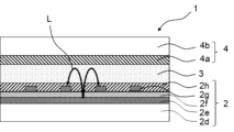
- FIG. 1 is a schematic cross-sectional view showing an example of a horizontal electric field liquid crystal display element of the present invention.
- FIG. 3 is a schematic cross-sectional view showing another example of the horizontal electric field liquid crystal display element of the present invention.
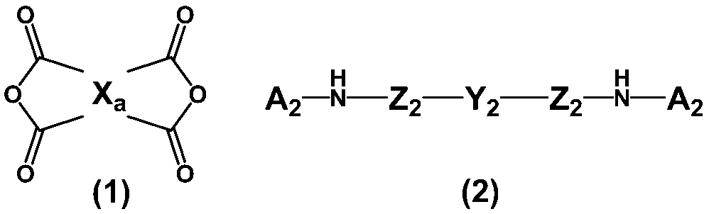
- the liquid crystal aligning agent of the present invention includes at least one type selected from the group consisting of tetracarboxylic dianhydride and its derivatives represented by the above formula (1) (in the present invention, a specific aromatic tetracarboxylic acid component (p ) and a diamine component containing a diamine represented by the above formula (2) (also referred to as a specific diamine (p) in the present invention); It contains at least one polymer (P) selected from the group consisting of polyimide, which is an imidized product of the polyimide precursor.
- the polymer (P) may be one type or two or more types.
- the polyimide precursor is a polymer that can be imidized to obtain polyimide, such as polyamic acid or polyamic acid ester.
- the polyamic acid (P') which is a polyimide precursor of the polymer (P) can be obtained by polymerizing, for example, a diamine component containing the above-mentioned specific diamine (p) and a tetracarboxylic dianhydride represented by the above formula (1). It can be obtained by reaction.
- the tetracarboxylic acid component to be reacted with the diamine component is not only tetracarboxylic dianhydride, but also tetracarboxylic acid, tetracarboxylic acid dihalide, tetracarboxylic acid dialkyl ester, or tetracarboxylic acid. Derivatives of tetracarboxylic dianhydrides such as dialkyl ester dihalides can also be used.
- X a in the above formula (1) represents a tetravalent organic group derived from an aromatic tetracarboxylic dianhydride or a derivative thereof.
- the aromatic tetracarboxylic dianhydride is an acid dianhydride obtained by intramolecular dehydration of four carboxy groups including at least one carboxy group bonded to an aromatic ring.
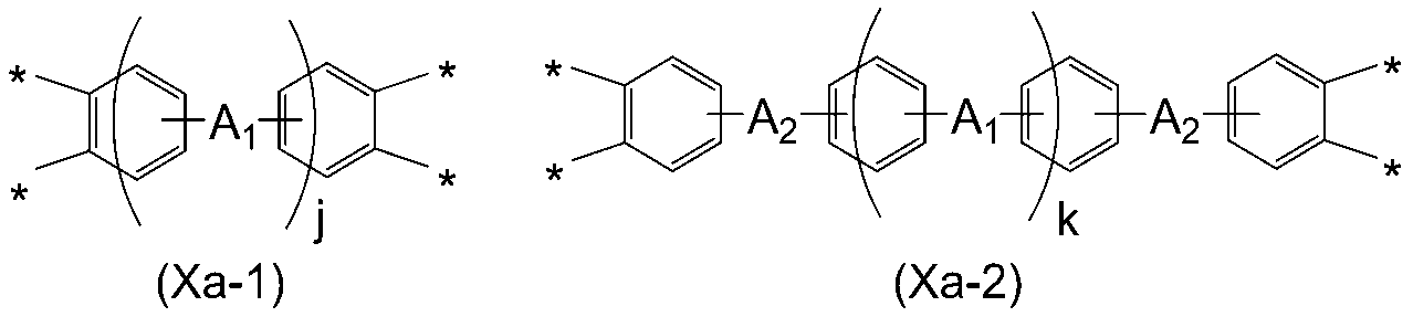
- X a in the above formula (1) is preferably a structure selected from the following formulas (Xa-1) and (Xa-2).
- j and k are integers of 0 or 1
- R represents a hydrogen atom or a methyl group.
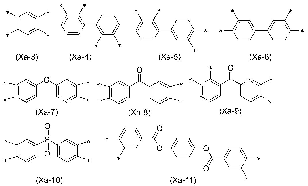
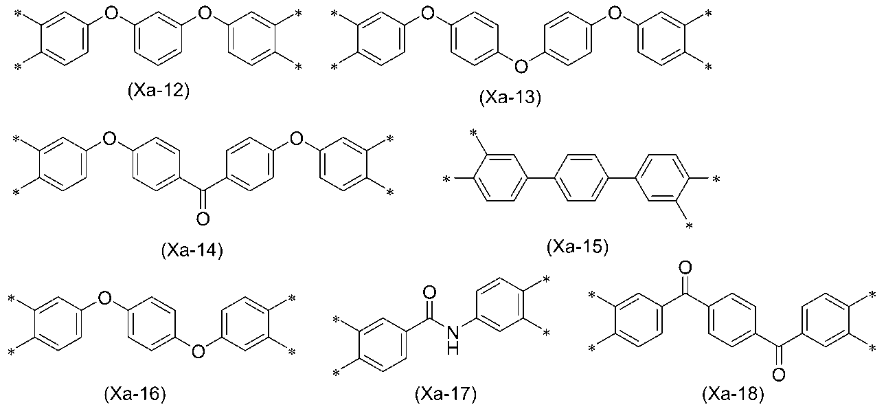
- Preferred specific examples of the above formulas (Xa-1) and (Xa-2) include the following formulas (Xa-3) to (Xa-18).
- X a is more preferably represented by the above formulas (Xa-3) to (Xa-7), and even more preferably represented by the above formulas (Xa-3) to (Xa-6).
- the proportion of the specific aromatic tetracarboxylic acid component (p) used is preferably 10 mol% or more, more preferably 20 mol% or more, based on 1 mol of the total tetracarboxylic acid components used in the polymer (P). Preferably, 50 mol% or more is more preferable.
- the tetracarboxylic acid component used in the production of the polymer (P) contains a tetracarboxylic acid component other than the above-mentioned specific aromatic tetracarboxylic acid component (p) (hereinafter also referred to as other tetracarboxylic acid component). You can stay there.
- the amount of the specific aromatic tetracarboxylic acid component (p) to be used depends on the polymer (P). It is preferably 90 mol% or less, more preferably 80 mol% or less, based on 1 mol of all the tetracarboxylic acid components used.
- Examples of the other tetracarboxylic acid components include acyclic aliphatic tetracarboxylic dianhydrides, alicyclic tetracarboxylic dianhydrides, and derivatives thereof.
- the acyclic aliphatic tetracarboxylic dianhydride is an acid dianhydride obtained by intramolecular dehydration of four carboxy groups bonded to a chain hydrocarbon structure.
- Alicyclic tetracarboxylic dianhydride is an acid dianhydride obtained by intramolecular dehydration of four carboxy groups including at least one carboxy group bonded to an alicyclic structure. However, none of these four carboxy groups is bonded to an aromatic ring. Further, it is not necessary to be composed only of an alicyclic structure, and a part thereof may have a chain hydrocarbon structure or an aromatic ring structure.
- acyclic aliphatic or alicyclic tetracarboxylic dianhydride is selected from the group consisting of a cyclobutane ring structure, a cyclopentane ring structure, and a cyclohexane ring structure, especially from the viewpoint of improving liquid crystal orientation.
- a tetracarboxylic dianhydride or a derivative thereof having at least one partial structure is preferable.
- the other tetracarboxylic acid component described above is preferably a tetracarboxylic dianhydride represented by the following formula (t) or a derivative thereof.
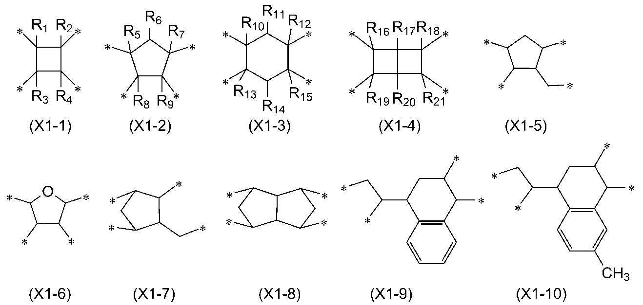
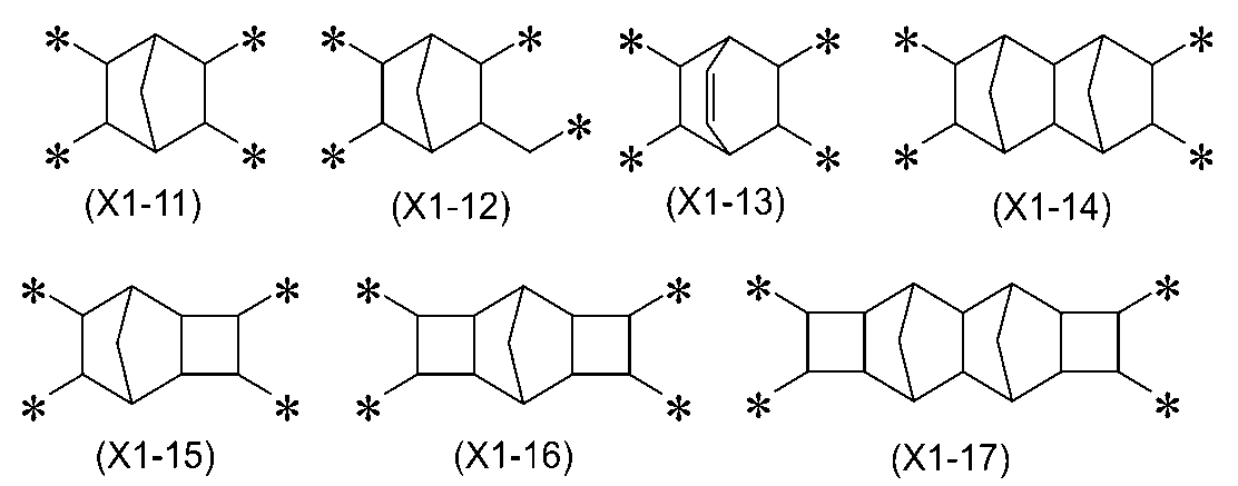
- X T is a structure selected from the following formulas (X1-1) to (X1-23).
- R 1 to R 21 are each independently a hydrogen atom, a halogen atom, an alkyl group having 1 to 6 carbon atoms, an alkenyl group having 2 to 6 carbon atoms, It represents an alkynyl group having 2 to 6 carbon atoms, a monovalent organic group having 1 to 6 carbon atoms containing a fluorine atom, or a phenyl group. From the viewpoint of liquid crystal alignment, R 1 to R 21 are each independently preferably a hydrogen atom, a halogen atom, a methyl group, or an ethyl group, and more preferably a hydrogen atom or a methyl group.
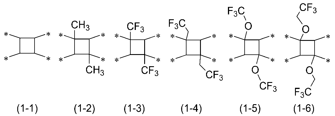
- formula (X1-1) include the following formulas (1-1) to (1-6). From the viewpoint of improving liquid crystal orientation, (1-1) to (1-2) are particularly preferred.
- the above X T is preferably the above formulas (X1-1) to (X1-10) or (X1-18) to (X1-23), and the above formulas (X1-1), (X1-5), (X1-7) to (X1-10), (X1-21), or (X1-23) are more preferable, and the above formulas (1-1), (1-2), (X1 -5), (X1-7), (X1-8), or (X1-9) are more preferred.
- the specific diamine (p) of the present invention is a diamine represented by the above formula (2).
- the above specific diamine (p) may be used alone or in combination of two or more.
- the usage amount of the specific diamine (p) is preferably 5 mol% or more, more preferably 10 mol% or more, and still more preferably 20 mol% or more, based on 1 mol of the diamine component used for producing the polymer (P). preferable.
- Y 2 in the above formula (2) represents a divalent organic group having 6 to 30 carbon atoms and containing one or more aromatic groups.
- the above-mentioned aromatic group refers to an aromatic hydrocarbon group or an aromatic heterocyclic group, and includes a monocyclic group, a condensed ring group, and a group in which monocycles or condensed rings are connected.
- Examples of the aromatic ring structure in the aromatic group include a benzene ring, a naphthalene ring, and a biphenyl structure. Any hydrogen atom of the aromatic group may be replaced with a monovalent group.
- the monovalent groups mentioned above include halogen atoms, alkyl groups having 1 to 10 carbon atoms, alkenyl groups having 2 to 10 carbon atoms, alkoxy groups having 1 to 10 carbon atoms, fluoroalkyl groups having 1 to 10 carbon atoms, and fluoroalkyl groups having 1 to 10 carbon atoms.
- Examples include a fluoroalkenyl group having 2 to 10 carbon atoms, a fluoroalkoxy group having 1 to 10 carbon atoms, a carboxy group, a hydroxy group, an alkyloxycarbonyl group having 1 to 10 carbon atoms, a cyano group, and a nitro group.
- Y 2 is preferably bonded to Z 2 through an atom forming an aromatic ring, and more preferably bonding to a carbon atom forming an aromatic ring. It is more preferable that the polymer (P) has the aromatic group of Y 2 in the main chain direction of the polymer (P).
- the main chain of a polymer refers to the part of the polymer that consists of the longest chain of atoms. "The polymer (P) has the aromatic group that Y2 has in the main chain direction of the polymer (P)" means that the aromatic group that Y2 has has the aromatic group that is present in the main chain of the polymer (P). It means to constitute.
- Y 2 preferably has a structure represented by the following formula (3).
- R represents a hydrogen atom, methyl group, or tert-butoxycarbonyl group
- cyclohexylene group or an alkylene group having 2 to 18 carbon atoms.
- R 3 represents a halogen atom, or an alkyl group or alkoxy group having 1 to 5 carbon atoms, and any hydrogen atom of the alkyl group or alkoxy group may be substituted with a halogen atom, and R 3 represents any hydrocarbon group. may be substituted with an amino group protected with a tert-butoxycarbonyl group.
- Each of the plurality of a's is an integer of 0 to 4, b is an integer of 1 to 2, and c is an integer of 0 to 1.
- p is an integer from 1 to 6, preferably from 2 to 6.
- q is an integer of 1 to 6, more preferably an integer of 2 to 6, and even more preferably an integer of 2 to 4.
- p', q', and r' are integers from 0 to 6. Furthermore, 0 ⁇ p'+q' ⁇ 10 is satisfied, and 2 ⁇ p'+q+r' ⁇ 16 is satisfied.
- Z 2 is each independently an alkylene group having 1 to 6 carbon atoms. From the viewpoint of improving liquid crystal orientation, methylene groups or ethylene groups are preferred. A 2 is an alkyl group having 1 to 6 carbon atoms. From the viewpoint of improving liquid crystal orientation, A 2 is preferably a methyl group or an ethyl group.
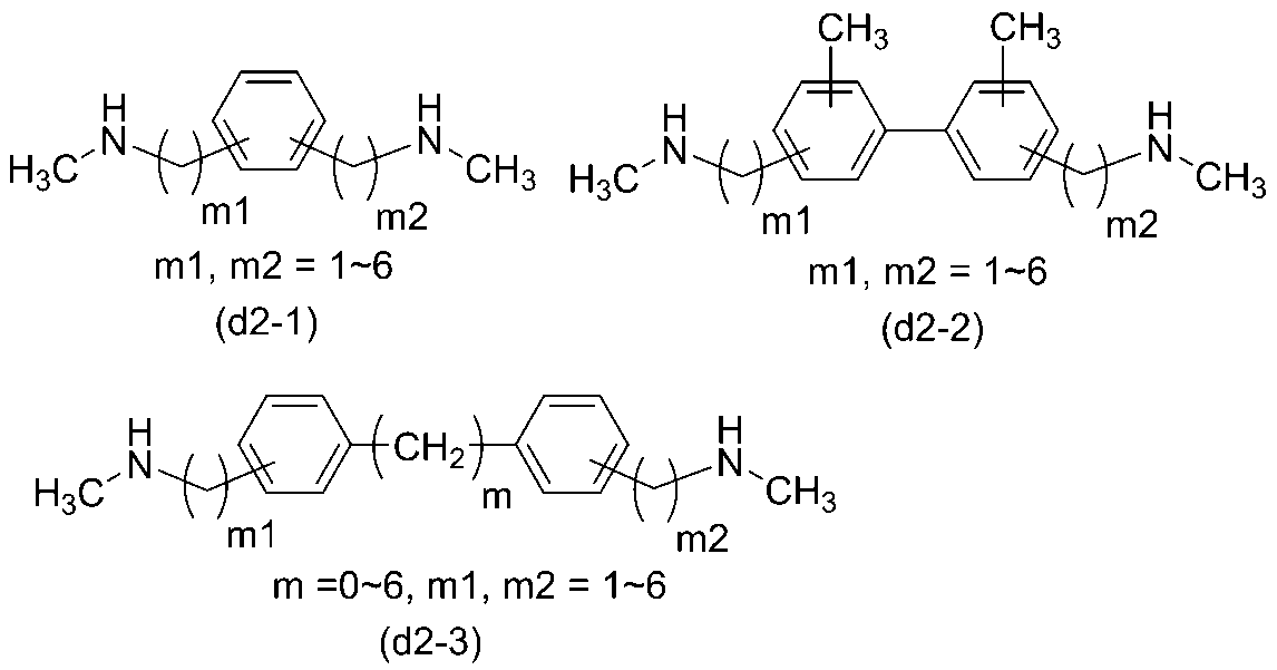
- diamine represented by the above formula (2) include diamines represented by any of the following formulas (d2-1) to (d2-3).
- the diamine component used in the production of the above polymer (P) may contain diamines other than the specific diamine (p) (hereinafter also referred to as other diamines).
- the amount of specific diamine (p) to be used with respect to the diamine component is based on 1 mole of the diamine component used in the production of the polymer (P). , is preferably 90 mol% or less, more preferably 80 mol% or less.
- Examples of other diamines are listed below, but are not limited to these.
- the other diamines mentioned above may be used alone or in combination of two or more.
- p-phenylenediamine m-phenylenediamine, 2,3,5,6-tetramethyl-p-phenylenediamine, 2,5-dimethyl-p-phenylenediamine, 2,4-dimethyl-m-phenylenediamine, 2, 5-diaminotoluene, 2,6-diaminotoluene, 2,2'-dimethyl-4,4'-diaminobiphenyl, 3,3'-dimethyl-4,4'-diaminobiphenyl, 3,3'-dimethoxy-4 , 4'-diaminobiphenyl, 3,3'-dihydroxy-4,4'-diaminobiphenyl, 2,2'-difluoro-4,4'-diaminobiphenyl, 3,3'-difluoro-4,4'-diamino biphenyl, 2,2'-bis(trifluoromethyl)-4,4'-diaminobiphenyl,
- Diamines having a photo-alignable group such as 4,4'-diaminoazobenzene or diaminotolane; Diamines having an amide bond such as 4,4'-diaminobenzanilide; 1,3-bis(4-aminophenyl)urea , 1,3-bis(4-aminobenzyl)urea, 1,3-bis(4-aminophenethyl)urea and other diamines having a urea bond; 2,6-diaminopyridine, 3,4-diaminopyridine, 2 , 4-diaminopyrimidine, 3,6-diaminocarbazole, N-methyl-3,6-diaminocarbazole, 1,4-bis-(4-aminophenyl)-piperazine, 3,6-diaminoacridine, N-ethyl- 3,6-diaminocarbazole, N-phenyl-3,6-diaminocarbazole,
- diamines having siloxane bonds such as 1,3-bis(3-aminopropyl)-tetramethyldisiloxane; metaxylylene diamine, 1,3-propanediamine, tetramethylene diamine, pentamethylene diamine, hexa Methylenediamine, 1,3-bis(aminomethyl)cyclohexane, 1,4-diaminocyclohexane, 4,4'-methylenebis(cyclohexylamine), formulas (Y-1) to (Y-167) described in WO2018/117239 diamine etc. in which two amino groups are bonded to a group represented by any one of ).
- m and n are each independently an integer of 0 to 3, satisfying 1 ⁇ m+n ⁇ 4.
- j is an integer of 0 or 1.
- X 1 is -(CH 2 ) a - (a is an integer from 1 to 15), -CONH-, -NHCO-, -CO-N(CH 3 )-, -NH-, -O-, Represents -CH 2 O-, -CH 2 -OCO-, -COO-, or -OCO-.
- R 1 is a fluorine atom, a fluorine atom-containing alkyl group having 1 to 10 carbon atoms, a fluorine atom-containing alkoxy group having 1 to 10 carbon atoms, an alkyl group having 1 to 10 carbon atoms, an alkoxy group having 1 to 10 carbon atoms, and Represents a monovalent group such as an alkoxyalkyl group having 2 to 10 carbon atoms.
- X 2 represents -O-, -CH 2 O-, -CH 2 -OCO-, -COO-, or -OCO-.
- Boc represents a tert-butoxycarbonyl group.
- Examples of the nitrogen atom-containing heterocycle that the diamine having the nitrogen atom-containing structure may have include pyrrole, imidazole, pyrazole, triazole, pyridine, pyrimidine, pyridazine, pyrazine, indole, benzimidazole, purine, quinoline, and isoquinoline. , naphthyridine, quinoxaline, phthalazine, triazine, carbazole, acridine, piperidine, piperazine, pyrrolidine, hexamethyleneimine. Among these, pyridine, pyrimidine, pyrazine, piperidine, piperazine, quinoline, carbazole or acridine are preferred.
- the above-mentioned other diamines include the first diamine, a diamine having an amide bond, a diamine having a urea bond, a diamine having a group "-N(D)-", and a specific nitrogen atom-containing diamine.
- the diamine may be selected from the group consisting of a diamine having a structure and a diamine having a carboxy group.
- the liquid crystal aligning agent of the present invention is a liquid composition in which the polymer (P) and other components used as necessary are preferably dispersed or dissolved in an appropriate solvent.
- the liquid crystal aligning agent of the present invention may contain other polymers than the polymer (P).
- other polymers include polyimide precursors obtained by using, in addition to the above polymer (P), a tetracarboxylic acid component that does not contain the above specific aromatic tetracarboxylic acid component (p); At least one polymer selected from the group consisting of polyimide, which is an imidized product of a polyimide precursor, a polyimide precursor obtained using a diamine component that does not have the above-mentioned specific diamine (p), and an imidized product of the polyimide precursor.
- a certain polyimide also referred to as polymer (B) in the present invention
- poly(styrene-maleic anhydride) copolymers include SMA1000, SMA2000, SMA3000 (manufactured by Cray Valley), GSM301 (manufactured by Gifu Cerac Manufacturing Co., Ltd.), and poly(isobutylene-maleic anhydride) copolymers include A specific example of the anhydride copolymer is Isoban-600 (manufactured by Kuraray Co., Ltd.).
- a specific example of the poly(vinyl ether-maleic anhydride) copolymer includes Gantrez AN-139 (methyl vinyl ether maleic anhydride resin, manufactured by Ashland Corporation).
- polymer (B) is more preferable from the viewpoint of reducing afterimages derived from residual DC.
- the other polymers mentioned above may be used alone or in combination of two or more.
- the content ratio of other polymers is preferably 90 parts by mass or less, more preferably 10 to 90 parts by mass, and further 20 to 80 parts by mass with respect to the total 100 parts by mass of the polymers contained in the liquid crystal aligning agent. preferable.
- the tetracarboxylic acid component used in the production of the polymer (B) include the same compounds as those exemplified for the polymer (P), including preferred specific examples.
- the tetracarboxylic acid component used for producing the polymer (B) is more preferably a tetracarboxylic dianhydride having at least one partial structure selected from the group consisting of a benzene ring, a cyclobutane ring, a cyclopentane ring, and a cyclohexane ring. It is more preferable to include a compound or a derivative thereof (hereinafter also referred to as a specific tetracarboxylic acid component (B)).
- the amount of the specific tetracarboxylic acid component (B) used is preferably 10 mol% or more, and 20 mol% or more, based on 1 mol of the total tetracarboxylic acid component used for producing the polymer (B). is more preferable, and even more preferably 50 mol% or more.
- Examples of the diamine component for obtaining the polymer (B) include the diamines exemplified for the polymer (P) above. Among these, at least one diamine selected from the group consisting of the first diamine, a diamine having a urea bond, a diamine having an amide bond, and a diamine having a group "-N(D)-" (in the present invention, these is also referred to as a specific diamine (b)).
- the diamine component one type of diamine may be used alone, or two or more types may be used in combination.
- the amount used is preferably 10 mol% or more, more preferably 20 mol% or more, based on the total diamine components used for producing the polymer (B).
- the amount of the specific diamine (b) used is preferably 90 mol% or less, and 80 mol% or less, based on 1 mol of the total diamine components used for producing the polymer (B). The following are more preferred.
- Polyamic acid is produced by reacting a diamine component and a tetracarboxylic acid component in an organic solvent.
- the ratio of the tetracarboxylic acid component and diamine component used in the polyamic acid production reaction is such that the acid anhydride group in the tetracarboxylic acid component is 0.5 to 2 equivalents per 1 equivalent of amino group in the diamine component.
- the ratio is preferably 0.8 to 1.2 equivalents, and more preferably 0.8 to 1.2 equivalents.
- the closer the equivalent of the acid anhydride group of the tetracarboxylic acid component is to 1 equivalent the larger the molecular weight of the polyamic acid produced becomes.
- the reaction temperature in the production of polyamic acid is preferably -20 to 150°C, more preferably 0 to 100°C. Further, the reaction time is preferably 0.1 to 24 hours, more preferably 0.5 to 12 hours. Polyamic acid can be produced at any concentration, but the concentration of polyamic acid is preferably 1 to 50% by mass, more preferably 5 to 30% by mass. It is also possible to carry out the reaction at a high concentration in the initial stage and then add a solvent.
- organic solvents include cyclohexanone, cyclopentanone, N-methyl-2-pyrrolidone, N-ethyl-2-pyrrolidone, ⁇ -butyrolactone, N,N-dimethylformamide, N,N-dimethylacetamide, dimethyl
- examples include sulfoxide and 1,3-dimethyl-2-imidazolidinone.
- the polymer has high solvent solubility, methyl ethyl ketone, cyclohexanone, cyclopentanone, 4-hydroxy-4-methyl-2-pentanone, propylene glycol monomethyl ether, ethylene glycol monomethyl ether, ethylene glycol monoethyl ether, ethylene Solvents such as glycol monopropyl ether, diethylene glycol monomethyl ether, or diethylene glycol monoethyl ether can be used.
- Polyamic acid esters can be produced by, for example, [I] a method of reacting the polyamic acid obtained by the above method with an esterifying agent, [II] a method of reacting a tetracarboxylic acid diester with a diamine, [III] a method of reacting a tetracarboxylic acid diester with a diamine, and [III] a method of reacting a tetracarboxylic acid diester with a diamine. It can be obtained by a known method such as a method of reacting a diester dihalide and a diamine.
- Polyimide can be obtained by ring-closing (imidizing) a polyimide precursor such as the above polyamic acid or polyamic acid ester.
- the imidization ratio as used herein refers to the ratio of imide groups to the total amount of imide groups and carboxy groups (or derivatives thereof) derived from tetracarboxylic dianhydride or its derivatives.
- the imidization rate does not necessarily have to be 100%, and can be arbitrarily adjusted depending on the use and purpose.
- Examples of methods for imidizing the polyimide precursor include thermal imidization, in which the polyimide precursor solution is directly heated, and catalytic imidization, in which a catalyst is added to the polyimide precursor solution.
- the temperature when thermally imidizing the polyimide precursor in a solution is preferably 100 to 400°C, more preferably 120 to 250°C, and it is preferable to carry out thermal imidization while removing water generated by the imidization reaction from the system. is preferred.
- Catalytic imidization of the polyimide precursor is carried out by adding a basic catalyst and an acid anhydride to a solution of the polyimide precursor, and stirring the mixture preferably at -20 to 250°C, more preferably at 0 to 180°C. Can be done.
- the amount of the basic catalyst is preferably 0.5 to 30 times the amount of the amic acid group, more preferably 2 to 20 times the amount, and the amount of the acid anhydride is preferably 1 to 50 times the amount of the amic acid group. Preferably it is 3 to 30 times the mole.
- the basic catalyst include pyridine, triethylamine, trimethylamine, tributylamine, trioctylamine, etc.
- pyridine is preferred because it has an appropriate basicity to allow the reaction to proceed.
- the acid anhydride include acetic anhydride, trimellitic anhydride, and pyromellitic anhydride.
- acetic anhydride is preferably used because it facilitates purification after the reaction is completed.
- the imidization rate by catalytic imidization can be controlled by adjusting the amount of catalyst, reaction temperature, and reaction time.
- the reaction solution may be poured into a solvent and precipitated.
- the solvent used for precipitation include methanol, ethanol, isopropyl alcohol, acetone, hexane, butyl cellosolve, heptane, methyl ethyl ketone, methyl isobutyl ketone, toluene, benzene, water, and the like.
- the polymer precipitated in a solvent can be collected by filtration and then dried under normal pressure or reduced pressure, at room temperature or by heating.
- the amount of impurities in the polymer can be reduced.
- the solvent at this time include alcohols, ketones, and hydrocarbons, and it is preferable to use three or more types of solvents selected from these, since the efficiency of purification will further increase.
- an appropriate end-capping agent is used together with a tetracarboxylic acid component containing tetracarboxylic dianhydride or a derivative thereof and a diamine component containing a diamine to form an end-capped type.
- Polymers may be produced.
- the terminal-capped polymer has the effects of improving the film hardness of the liquid crystal alignment film obtained by coating and improving the adhesion characteristics between the sealant and the liquid crystal alignment film.
- Examples of the terminals of the polyimide precursor and polyimide in the present invention include amino groups, carboxy groups, acid anhydride groups, and groups derived from the terminal capping agent described below.
- the amino group, carboxy group, and acid anhydride group can be obtained by a conventional condensation reaction or by capping the terminal using the terminal capping agent shown below.
- terminal capping agent examples include acetic anhydride, maleic anhydride, nadic anhydride, phthalic anhydride, itaconic anhydride, 1,2-cyclohexanedicarboxylic anhydride, 3-hydroxyphthalic anhydride, and trimellitic anhydride.
- Examples include isocyanates having unsaturated bonds.
- the proportion of the terminal capping agent used is preferably 0.01 to 20 parts by mole, more preferably 0.01 to 10 parts by mole, based on a total of 100 parts by mole of the diamine component used.
- the weight average molecular weight (Mw) in terms of polystyrene measured by gel permeation chromatography (GPC) of the polyimide precursor and polyimide is preferably 1,000 to 500,000, more preferably 2,000 to 300,000. It is. Further, the molecular weight distribution (Mw/Mn) expressed as the ratio of Mw to the number average molecular weight (Mn) in terms of polystyrene measured by GPC is preferably 15 or less, more preferably 10 or less. By having a molecular weight within this range, good liquid crystal alignment of the liquid crystal display element can be ensured.
- the organic solvent contained in the liquid crystal aligning agent according to the present invention is not particularly limited as long as it can uniformly dissolve the polymer (P) and other polymers added as necessary.
- P polymer
- N-ethyl-2-pyrrolidone dimethyl sulfoxide, ⁇ -butyrolactone, ⁇ -valerolactone, 1,3-dimethyl-2-imidazolidinone, methyl ethyl ketone, cyclohexanone, cyclopentanone, 3-methoxy-N,N-dimethyl Propanamide, 3-butoxy-N,N-dimethylpropanamide, N-(n-propyl)-2-pyrrolidone, N-isopropyl-2-pyrrolidone, N-(n-butyl)-2-pyrrolidone, N-( tert-butyl)-2-pyrrolidone, N-(n-pentyl)-2-pyrrolidone, N-methoxypropyl-2-pyrrolidone, N-ethoxyethyl-2-pyrrolidone, N-methoxybutyl-2-pyrrolidone, N- Examples include cyclol
- N-methyl-2-pyrrolidone, N-ethyl-2-pyrrolidone, 3-methoxy-N,N-dimethylpropanamide, 3-butoxy-N,N-dimethylpropanamide or ⁇ -butyrolactone are preferred.
- the content of the good solvent is preferably 20 to 99% by mass, more preferably 20 to 90% by mass, and particularly preferably 30 to 80% by mass of the total solvent contained in the liquid crystal aligning agent.
- the organic solvent contained in the liquid crystal aligning agent is a mixture of the above solvents and a solvent (also referred to as a poor solvent) that improves the coating properties and surface smoothness of the coating film when applying the liquid crystal aligning agent. Preference is given to using a solvent. Specific examples of poor solvents are shown below, but are not limited thereto.
- the content of the poor solvent is preferably 1 to 80% by mass, more preferably 10 to 80% by mass, and particularly preferably 20 to 70% by mass of the total solvent contained in the liquid crystal aligning agent.
- the type and content of the poor solvent are appropriately selected depending on the liquid crystal aligning agent coating device, coating conditions, coating environment, and the like.
- the poor solvent examples include diisopropyl ether, diisobutyl ether, diisobutyl carbinol (2,6-dimethyl-4-heptanol), ethylene glycol dimethyl ether, ethylene glycol diethyl ether, ethylene glycol dibutyl ether, 1,2-dibutoxyethane, Diethylene glycol dimethyl ether, diethylene glycol diethyl ether, 4-hydroxy-4-methyl-2-pentanone, diethylene glycol methyl ethyl ether, diethylene glycol dibutyl ether, 3-ethoxybutyl acetate, 1-methylpentyl acetate, 2-ethyl butyl acetate, 2 - Ethylhexyl acetate, ethylene glycol monoacetate, ethylene glycol diacetate, propylene carbonate, ethylene carbonate, ethylene glycol monobutyl ether, ethylene glycol monoisoamyl ether, ethylene glycol monohexyl
- diisobutyl carbinol propylene glycol monobutyl ether, propylene glycol diacetate, diethylene glycol diethyl ether, dipropylene glycol monomethyl ether, dipropylene glycol dimethyl ether, 4-hydroxy-4-methyl-2-pentanone, ethylene glycol monobutyl ether, ethylene Glycol monobutyl ether acetate or diisobutyl ketone is preferred.
- Preferred solvent combinations of good and poor solvents include N-methyl-2-pyrrolidone and ethylene glycol monobutyl ether, N-methyl-2-pyrrolidone, ⁇ -butyrolactone and ethylene glycol monobutyl ether, and N-methyl-2-pyrrolidone and ⁇ -butyrolactone and ethylene glycol monobutyl ether.
- the liquid crystal aligning agent of the present invention contains the above-mentioned polymer (P), and if necessary, the above-mentioned other polymers and the above-mentioned organic solvent.
- the total content of the polymers contained in the liquid crystal aligning agent of the present invention can be changed as appropriate depending on the thickness of the coating film to be formed, but from the viewpoint of forming a uniform and defect-free coating film, the total content is 1 mass. % or more, and from the viewpoint of storage stability of the solution, 10% by mass or less is preferable.
- a particularly preferred total polymer content is 2 to 8% by weight.
- the content of the polymer (P) used in the present invention is preferably 1 to 100% by mass, more preferably 10 to 100% by mass, and 20 to 100% by mass based on the total amount of polymers contained in the liquid crystal aligning agent. % is particularly preferred.
- the liquid crystal aligning agent of the present invention may contain other components (hereinafter also referred to as additive components) in addition to the polymer (P), the other polymers, and the organic solvent. Examples of such additive components include crosslinkable compounds having at least one substituent selected from oxiranyl groups, oxetanyl groups, blocked isocyanate groups, oxazoline groups, cyclocarbonate groups, hydroxy groups, and alkoxy groups, and polymerizable inorganic compounds.
- At least one crosslinkable compound selected from the group consisting of crosslinkable compounds having a saturated group, a functional silane compound, a metal chelate compound, a curing accelerator, a surfactant, an antioxidant, a sensitizer, a preservative, Examples include compounds for adjusting the dielectric constant and electrical resistance of the liquid crystal alignment film.
- crosslinkable compound examples include ethylene glycol diglycidyl ether, polyethylene glycol diglycidyl ether, propylene glycol diglycidyl ether, tripropylene glycol diglycidyl ether, polypropylene glycol diglycidyl ether, neopentyl glycol diglycidyl ether, 1 , 6-hexanediol diglycidyl ether, glycerin diglycidyl ether, dibromoneopentyl glycol diglycidyl ether, 1,3,5,6-tetraglycidyl-2,4-hexanediol, Epicote 828 (manufactured by Mitsubishi Chemical Corporation), etc.
- Bisphenol A type epoxy resins Bisphenol F type epoxy resins such as Epicote 807 (manufactured by Mitsubishi Chemical Corporation), hydrogenated bisphenol A type epoxy resins such as YX-8000 (manufactured by Mitsubishi Chemical Corporation), YX6954BH30 (manufactured by Mitsubishi Chemical Corporation), etc.
- Biphenyl skeleton-containing epoxy resins phenol novolac type epoxy resins such as EPPN-201 (manufactured by Nippon Kayaku Co., Ltd.), (o, m, p-) cresol novolac type epoxy resins such as EOCN-102S (manufactured by Nippon Kayaku Co., Ltd.), Triglycidyl isocyanurate such as TEPIC (manufactured by Nissan Chemical Co., Ltd.), alicyclic epoxy resin such as Celloxide 2021P (manufactured by Daicel Corporation), N,N,N',N'-tetraglycidyl-m-xylylenediamine, 1, A compound containing a tertiary nitrogen atom represented by 3-bis(N,N-diglycidylaminomethyl)cyclohexane or N,N,N',N'-tetraglycidyl-4,4'-diaminodiphenylmethane, Compounds having
- Examples of compounds for adjusting the dielectric constant and electrical resistance include monoamines having a nitrogen atom-containing aromatic heterocycle such as 3-picolylamine.
- the content of the monoamine having a nitrogen atom-containing aromatic heterocycle is preferably 0.1 to 30 parts by mass, more preferably 0.1 to 20 parts by mass, based on 100 parts by mass of the polymer component contained in the liquid crystal aligning agent. Part by mass.
- Preferred specific examples of the functional silane compounds include 3-aminopropyltrimethoxysilane, 3-aminopropyltriethoxysilane, 3-aminopropyldiethoxymethylsilane, 2-aminopropyltrimethoxysilane, and 2-aminopropyltrimethoxysilane.
- the solid content concentration in the liquid crystal aligning agent (the ratio of the total mass of components other than the solvent of the liquid crystal aligning agent to the total mass of the liquid crystal aligning agent) is appropriately selected in consideration of viscosity, volatility, etc., but is preferably It is 1 to 10% by mass.
- the particularly preferable solid content concentration range varies depending on the method used when applying the liquid crystal aligning agent to the substrate. For example, when using a spin coating method, it is particularly preferable that the solid content concentration is 1.5 to 4.5% by mass. When the printing method is used, it is particularly preferable that the solid content concentration is 3 to 9% by mass, and thereby the solution viscosity is 12 to 50 mPa ⁇ s.
- the solid content concentration be 1 to 5% by mass and the solution viscosity be 3 to 15 mPa ⁇ s.
- the temperature when preparing the polymer composition is preferably 10 to 50°C, more preferably 20 to 30°C.
- a liquid crystal aligning film can be manufactured by using the above-mentioned liquid crystal aligning agent.
- the liquid crystal display element of the present invention includes the liquid crystal alignment film described above.
- the operation mode of the liquid crystal display element according to the present invention is not particularly limited, and may be, for example, TN type, STN (Super Twisted Nematic) type, vertical alignment type (including VA-MVA type, VA-PVA type, etc.), IPS type, It can be applied to various operation modes such as FFS method and optically compensated bend type (OCB type).
- the liquid crystal alignment film of the present invention is particularly suitable for horizontal alignment type liquid crystal display elements such as IPS mode or FFS mode.
- the liquid crystal display element of the present invention can be produced, for example, by a method including the following steps (1) to (4), a method including steps (1) to (2) and (4), and a method including steps (1) to (3), (4). ) and (5), or by a method including steps (1) to (3), (4) and (6).
- Step (1) is a step of applying the liquid crystal aligning agent of the present invention onto a substrate.
- a specific example of step (1) is as follows.
- the liquid crystal aligning agent of the present invention is applied onto one surface of the substrate provided with the patterned transparent conductive film by an appropriate coating method such as a roll coater method, a spin coat method, a printing method, an inkjet method, or the like.
- the substrate is not particularly limited as long as it is a highly transparent substrate, and in addition to glass substrates and silicon nitride substrates, plastic substrates such as acrylic substrates and polycarbonate substrates can also be used.
- an opaque material such as a silicon wafer can be used as long as only one substrate is used, and in this case, a material that reflects light such as aluminum can also be used for the electrodes.
- a substrate is provided with an electrode made of a transparent conductive film or a metal film patterned in a comb shape, and a counter substrate is not provided with an electrode. and use.
- Examples of methods for applying the liquid crystal aligning agent to the substrate to form a film include screen printing, offset printing, flexographic printing, an inkjet method, and a spray method. Among these, coating and film forming methods using an inkjet method can be suitably used.
- Step (2) is a step of baking the liquid crystal alignment agent applied onto the substrate to form a film.
- a specific example of step (2) is as follows. After applying the liquid crystal aligning agent onto the substrate in step (1), the solvent is evaporated by heating means such as a hot plate, a thermal circulation oven, or an IR (infrared ray) oven, or the polyamic acid or polyamic acid ester is heated. It is also possible to perform thermal imidization.
- the drying and baking steps after applying the liquid crystal aligning agent of the present invention can be performed at any temperature and time, and may be performed multiple times.
- the temperature at which the solvent of the liquid crystal aligning agent is reduced can be, for example, 40 to 180°C.
- the firing time is not particularly limited, but examples include 1 to 10 minutes or 1 to 5 minutes.
- a step of firing at a temperature range of 150 to 300° C. or 150 to 250° C. may be added after the above steps.
- the firing time is not particularly limited, but examples include a firing time of 5 to 40 minutes or 5 to 30 minutes.
- the thickness of the film-like material after firing is preferably 5 to 300 nm, more preferably 10 to 200 nm, since reliability of the liquid crystal display element may decrease if it is too thin.
- Step (3) is a step of subjecting the film obtained in step (2) to an orientation treatment, depending on the case. That is, in a horizontal alignment type liquid crystal display element such as an IPS system or an FFS system, the coating film is subjected to an alignment ability imparting treatment. On the other hand, in a vertical alignment type liquid crystal display element such as a VA system or a PSA system, the formed coating film can be used as a liquid crystal alignment film as it is, but the coating film may be subjected to an alignment ability imparting treatment. Examples of the alignment treatment method for the liquid crystal alignment film include a rubbing treatment method and a photo alignment treatment method.
- the surface of the film-like material is irradiated with radiation polarized in a certain direction, and optionally, heat treatment is preferably performed at a temperature of 150 to 250°C to improve liquid crystal alignment (liquid crystal alignment).
- heat treatment is preferably performed at a temperature of 150 to 250°C to improve liquid crystal alignment (liquid crystal alignment).
- One example is the method of imparting the ability (also called Noh).
- the radiation ultraviolet rays or visible light having a wavelength of 100 to 800 nm can be used. Among these, ultraviolet light having a wavelength of preferably 100 to 400 nm, more preferably 200 to 400 nm.
- Examples of the above-mentioned rubbing treatment include a treatment in which the coating film is rubbed in a certain direction with a roll wrapped around a cloth made of fibers such as nylon, rayon, and cotton.
- the radiation when the radiation is polarized light, it may be linearly polarized light or partially polarized light. Further, when the radiation used is linearly polarized light or partially polarized light, irradiation may be performed from a direction perpendicular to the substrate surface, from an oblique direction, or a combination of these may be performed. When irradiating non-polarized radiation, the direction of irradiation is preferably oblique.
- Step (4) Step of producing a liquid crystal cell> Two substrates each having a liquid crystal alignment film formed thereon as described above are prepared, and a liquid crystal is placed between the two substrates which are placed facing each other. Specifically, the following two methods can be mentioned. In the first method, first, two substrates are placed facing each other with a gap (cell gap) in between so that the respective liquid crystal alignment films face each other. Next, the peripheral parts of the two substrates are bonded together using a sealant, and a liquid crystal composition is injected and filled into the cell gap defined by the substrate surface and the sealant to contact the film surface, and then the injection hole is sealed. Stop.
- the second method is a technique called ODF (One Drop Fill) method.
- ODF One Drop Fill
- an ultraviolet light-curable sealant is applied to a predetermined location on one of the two substrates on which a liquid crystal alignment film has been formed, and a liquid crystal composition is further applied to several predetermined locations on the surface of the liquid crystal alignment film. drip.
- the other substrate is bonded together so that the liquid crystal alignment films face each other, and the liquid crystal composition is spread over the entire surface of the substrate and brought into contact with the film surface.
- the entire surface of the substrate is irradiated with ultraviolet light to cure the sealant.
- the two substrates are arranged facing each other so that the rubbing directions of each coating film are at a predetermined angle, for example, perpendicular or antiparallel to each other.
- the sealant for example, an epoxy resin containing a hardening agent and aluminum oxide spheres as a spacer can be used.
- the liquid crystal composition is not particularly limited, and various liquid crystal compositions containing at least one type of liquid crystal compound (liquid crystal molecule) and having positive or negative dielectric anisotropy can be used.
- a liquid crystal composition having a positive dielectric anisotropy is also referred to as a positive type liquid crystal
- a liquid crystal composition having a negative dielectric anisotropy is also referred to as a negative type liquid crystal.
- the liquid crystal composition may include a fluorine atom, a hydroxy group, an amino group, a fluorine atom-containing group (for example, a trifluoromethyl group), a cyano group, an alkyl group, an alkoxy group, an alkenyl group, an isothiocyanate group, a heterocycle, a cycloalkane, It may contain a liquid crystal compound having a cycloalkene, a steroid skeleton, a benzene ring, or a naphthalene ring, and a compound having two or more rigid sites (mesogen skeletons) that exhibit liquid crystallinity within the molecule (for example, two rigid biphenyl structure, or a bimesogenic compound in which a terphenyl structure is connected with an alkylene group).
- a fluorine atom for example, a trifluoromethyl group
- a cyano group for example, an alkyl group, an alkoxy group,
- the liquid crystal composition may be a liquid crystal composition exhibiting a nematic phase, a liquid crystal composition exhibiting a smectic phase, or a liquid crystal composition exhibiting a cholesteric phase.
- the above-mentioned liquid crystal composition may further contain an additive from the viewpoint of improving liquid crystal alignment.
- additives include photopolymerizable monomers such as compounds having polymerizable groups; optically active compounds (e.g. S-811 manufactured by Merck & Co., Ltd.); antioxidants; ultraviolet absorbers; pigments; Examples include antifoaming agents; polymerization initiators; and polymerization inhibitors.
- Examples of the positive liquid crystal include ZLI-2293, ZLI-4792, MLC-2003, MLC-2041, and MLC-7081 manufactured by Merck & Co., Ltd.
- Examples of the negative type liquid crystal include MLC-6608, MLC-6609, MLC-6610, and MLC-7026-100 manufactured by Merck & Co., Ltd.
- a liquid crystal containing a compound having a polymerizable group MLC-3023 manufactured by Merck & Co., Ltd. can be mentioned.
- the liquid crystal aligning agent of the present invention has a liquid crystal layer between a pair of substrates provided with electrodes, and has a liquid crystal composition containing a polymerizable compound that is polymerized by at least one of active energy rays and heat between the pair of substrates.
- a step of arranging objects and polymerizing a polymerizable compound by at least one of active energy ray irradiation and heating while applying a voltage between electrodes hereinafter, this step is also referred to as step (5)). It is also preferably used for liquid crystal display elements (PSA type liquid crystal display elements).
- the liquid crystal aligning agent of the present invention has a liquid crystal layer between a pair of substrates provided with electrodes, and a polymerizable group that is polymerized by at least one of active energy rays and heat is provided between the pair of substrates.
- a liquid crystal display element (SC-PVA type liquid crystal display element) manufactured through a step of arranging a liquid crystal alignment film containing the liquid crystal alignment film and applying a voltage between the electrodes (hereinafter, this step is also referred to as step (6)).
- this step (6) Preferably used.
- a liquid crystal display element can be obtained by bonding a polarizing plate to the outer surface of the liquid crystal cell, if necessary.
- the polarizing plate bonded to the outer surface of the liquid crystal cell is a polarizing plate in which a polarizing film called "H film” made by stretching and aligning polyvinyl alcohol and absorbing iodine is sandwiched between cellulose acetate protective films, or the H film itself.
- a polarizing plate consisting of:
- An IPS substrate which is a comb-teeth electrode substrate used in the IPS method, includes a base material, a plurality of linear electrodes formed on the base material and arranged in a comb-teeth pattern, and a base material that covers the linear electrodes. It has a liquid crystal alignment film formed as shown in FIG.
- the FFS substrate which is a comb-teeth electrode substrate used in the FFS method, consists of a base material, a surface electrode formed on the base material, an insulating film formed on the surface electrode, and an insulating film formed on the insulating film. , has a plurality of linear electrodes arranged in a comb-teeth shape, and a liquid crystal alignment film formed on an insulating film so as to cover the linear electrodes.
- FIG. 1 is a schematic cross-sectional view showing an example of a horizontal electric field liquid crystal display element of the present invention, and is an example of an IPS type liquid crystal display element.
- a liquid crystal 3 is sandwiched between a comb-teeth electrode substrate 2 having a liquid crystal alignment film 2c and a counter substrate 4 having a liquid crystal alignment film 4a.
- the comb-teeth electrode substrate 2 includes a base material 2a, a plurality of linear electrodes 2b formed on the base material 2a and arranged in a comb-teeth shape, and a plurality of linear electrodes 2b formed on the base material 2a so as to cover the linear electrodes 2b.
- the counter substrate 4 has a base material 4b and a liquid crystal alignment film 4a formed on the base material 4b.
- the liquid crystal alignment film 2c is, for example, the liquid crystal alignment film of the present invention.
- the liquid crystal alignment film 4c is also the liquid crystal alignment film of the present invention.
- this horizontal electric field liquid crystal display element 1 when a voltage is applied to the linear electrodes 2b, an electric field is generated between the linear electrodes 2b as shown by lines of electric force L.
- FIG. 2 is a schematic cross-sectional view showing another example of the horizontal electric field liquid crystal display element of the present invention, and is an example of an FFS type liquid crystal display element.
- a liquid crystal 3 is sandwiched between a comb-teeth electrode substrate 2 having a liquid crystal alignment film 2h and a counter substrate 4 having a liquid crystal alignment film 4a.
- the comb-teeth electrode substrate 2 is formed on a base material 2d, a surface electrode 2e formed on the base material 2d, an insulating film 2f formed on the surface electrode 2e, and an insulating film 2f, and has a comb-like shape.
- the counter substrate 4 has a base material 4b and a liquid crystal alignment film 4a formed on the base material 4b.
- the liquid crystal alignment film 2h is, for example, the liquid crystal alignment film of the present invention.
- the liquid crystal alignment film 4a is also the liquid crystal alignment film of the present invention.
- the liquid crystal alignment film of the present invention can be applied to various uses other than the liquid crystal alignment film for the above-mentioned uses, such as a liquid crystal alignment film for a retardation film, a liquid crystal alignment film for a scanning antenna or a liquid crystal array antenna, or a liquid crystal alignment film for a scanning antenna or a liquid crystal array antenna. It can also be used as a liquid crystal alignment film for a transmission scattering type liquid crystal light control element. Furthermore, applications other than liquid crystal alignment films, such as protective films (e.g., protective films for color filters), spacer films, interlayer insulation films, antireflection films, wiring coating films, antistatic films, motor insulation films (flexible It can also be used as a gate insulating film for displays.
- protective films e.g., protective films for color filters
- spacer films interlayer insulation films
- antireflection films e.g., antireflection films
- wiring coating films e.g., antistatic films
- motor insulation films flexible It can also be used as a gate
- the liquid crystal display element of the present invention can be effectively applied to various devices, such as watches, portable games, word processors, notebook computers, car navigation systems, camcorders, PDAs, digital cameras, mobile phones, smartphones, It can be used in various display devices such as various monitors, liquid crystal televisions, and information displays.
- (diamine) DA-1 to DA-3 Compounds represented by the following formulas (DA-1) to (DA-3), respectively.
- the compounds represented by the above formula (DA-1) are the specific diamines (p)
- the compounds represented by the above formulas (DA-2) to (DA-3) are compounds included in the range of other diamines.
- DA-1 was synthesized according to the synthesis method described in WO2015/030071.
- GPC device GPC-101 (manufactured by Showa Denko), column: GPC KD-803, GPC KD-805 (manufactured by Showa Denko) in series, column temperature: 50°C, eluent: N,N-dimethylformamide (added)
- lithium bromide monohydrate LiBr H 2 O
- phosphoric acid/anhydrous crystal o-phosphoric acid
- tetrahydrofuran (THF) 10 mL/L
- flow rate 1.0 mL/min Standard sample for creating a calibration curve: TSK standard polyethylene oxide (molecular weight: approx. 900,000, 150,000, 100,000 and 30,000) (manufactured by Tosoh Corporation) and polyethylene glycol (molecular weight: approx. 12, 000, 4,000 and 1,000) (manufactured by Polymer Laboratory).
- DA-2 (1.50 g, 10.00 mmol) and NMP (11.3 g) were added to a 50 mL four-necked flask equipped with a stirrer and dissolved by stirring at room temperature. Then, by adding CA-1 (2.93 g, 9.95 mmol) and NMP (20.0 g) and stirring at 50°C for 24 hours, a polyamic acid solution (PAA2) with a solid content concentration of 12% by mass (viscosity :302 mPa ⁇ s) was obtained. This polyamic acid had Mn of 5,600 and Mw of 11,900.
- DA-3 (2.04 g, 15.0 mmol) and NMP (15.1 g) were added to a 50 mL four-necked flask equipped with a stirrer and dissolved by stirring at room temperature. Then, by adding CA-1 (4.06 g, 13.8 mmol) and NMP (29.8 g) and stirring at room temperature for 3 hours, a polyamic acid solution (PAA3) with a solid content concentration of 12% by mass (viscosity: 356 mPa ⁇ s) was obtained. This polyamic acid had Mn of 5,200 and Mw of 13,800.
- Example 1 The polyamic acid solution (PAA1) obtained in Synthesis Example 1 was diluted with NMP, GBL, and BCS, and stirred at room temperature for 2 hours to determine the mass ratio of polymer solid content to each solvent (polymer solid content: NMP: A liquid crystal aligning agent (AL-1) with GBL:BCS) of 4:46:30:20 was obtained. No abnormalities such as turbidity or precipitation were observed in this liquid crystal aligning agent, and it was confirmed that it was a uniform solution.
- Liquid crystal alignment agents AL-R1 and AL-R2 were prepared in the same manner as in Example 1 except that PAA2 and PAA3 were used instead of PAA1, respectively. Table 1 shows the composition of each liquid crystal aligning agent obtained in Examples and Comparative Examples. In Table 1, the numerical value in parentheses of the composition ratio represents the ratio (parts by mass) of each component to 100 parts by mass of the components of the liquid crystal aligning agent.
- a liquid crystal cell having a configuration of a fringe field switching (FFS) mode liquid crystal display element was manufactured.
- a substrate with electrodes was prepared.
- the substrate used was a glass substrate measuring 30 mm x 35 mm and having a thickness of 0.7 mm.
- An ITO electrode with a solid pattern constituting a counter electrode is formed as a first layer on the substrate, and a CVD (chemical vapor deposition) electrode is formed as a second layer on top of the first layer counter electrode.
- a SiN (silicon nitride) film was formed using a method.
- As the second layer SiN film a film having a thickness of 300 nm and functioning as an interlayer insulating film was used.
- a comb-shaped pixel electrode formed by patterning an ITO film as a third layer is arranged on the second layer of SiN film, and two pixels, a first pixel and a second pixel, are formed.
- the size of each pixel was 10 mm in length and about 5 mm in width.
- the first-layer counter electrode and the third-layer pixel electrode were electrically insulated by the action of the second-layer SiN film.
- the third layer pixel electrode has a comb-shaped shape in which a plurality of electrode elements each having a width of 3 ⁇ m and whose central portion is bent at an internal angle of 160° are arranged in parallel with an interval of 6 ⁇ m.
- Each pixel had a first region and a second region separated by a line connecting the bent portions of the plurality of electrode elements. Comparing the first region and the second region of each pixel, it was found that the formation directions of the electrode elements of the pixel electrodes constituting the first region and the second region were different. That is, when the line connecting the bent portions of the plurality of electrode elements is used as a reference, the electrode elements of the pixel electrode are formed at an angle of 80° clockwise in the first region of the pixel, and in the second region of the pixel. In this case, the electrode elements of the pixel electrode were formed at an angle of 80° counterclockwise.
- the directions of rotational movement (in-plane switching) within the substrate plane of the liquid crystal induced by voltage application between the pixel electrode and the counter electrode are mutually different. It was configured to run in the opposite direction.
- the liquid crystal aligning agent obtained above was filtered through a filter with a pore size of 1.0 ⁇ m, and then applied to the surface of the electrode-equipped substrate (first glass substrate) prepared above by a spin coating method.
- baking was performed for 20 minutes in a hot air circulation oven at 230° C. to obtain a polyimide film with a thickness of 60 nm.
- This polyimide film was rubbed and oriented with a rayon cloth (HY-5318 manufactured by Hyperflex) (roller diameter: 120 mm, roller rotation speed: 1000 rpm, moving speed: 30 mm/sec, pushing length: 0.4 mm, rubbing direction: third
- the direction was 180° C. with respect to the direction connecting the bent portions of the plurality of electrode elements of the pixel electrode of the second layer.
- it was washed by ultrasonic irradiation in pure water for 1 minute, water droplets were removed by air blowing, and then dried in an oven at 80° C. for 15 minutes to obtain a substrate with a liquid crystal alignment film.
- a glass substrate having a columnar spacer with a height of 4 ⁇ m and an ITO electrode formed on the back surface was also treated in the same manner as above to obtain a substrate with a liquid crystal alignment film subjected to alignment treatment.
- Ta a sealant (XN-1500T manufactured by Mitsui Chemicals) is printed on one substrate leaving a liquid crystal injection port on the other substrate. They were bonded together so that the alignment film surfaces faced each other and the rubbing directions were antiparallel. Thereafter, heat treatment was performed at 150° C. for 60 minutes to harden the sealant, and empty cells with a cell gap of 4 ⁇ m were produced.
- Negative liquid crystal MLC-7026-100 (manufactured by Merck & Co., Ltd.) was injected into this empty cell by a reduced pressure injection method, and the injection port was sealed to obtain an FFS type liquid crystal cell. Thereafter, the obtained liquid crystal cell was heated at 120° C. for 1 hour and left at 23° C. overnight before being used for evaluation.
- the liquid crystal cell was driven by applying an AC voltage with a frequency of 30 Hz, and the AC drive was performed so that the transmittance inside the cell became 100% every 3 minutes.
- the curve was measured and the offset voltage that minimized flicker was calculated. Thereafter, the amount of change in the minimum offset voltage value was measured every 3 minutes, and the maximum voltage value when changing within 30 minutes from immediately after lighting was calculated. At that time, if the amount of change in the maximum offset voltage exceeded 20 mV, it was defined as "defective" and evaluated. Further, when the amount of change in the maximum offset voltage did not exceed 20 mV, it was defined as "good” and evaluated.
- the flicker amplitude is determined by converting the transmitted light of the LED backlight that has passed through two polarizing plates and the liquid crystal cell between them into a data acquisition/data logger switch unit 34410A (KEYSIGHT Co., Ltd.) connected via a photodiode and an IV conversion amplifier. (Manufactured).
- z is the value of the brightness read by the data collection/data logger switch unit 34410A when driven with an AC voltage with a frequency of 30 Hz, which gives a relative transmittance of 23%.
- the evaluation of photoresponsiveness is "good” if the amount of change in flicker level remains less than 3% within 30 minutes from the time when the LED backlight is turned on and the application of AC voltage is started. When the above was reached, it was defined as “poor” and evaluated. The results are shown in Table 2. Note that the evaluation of photoresponsiveness according to the method described above was performed under room temperature conditions.
- Example 1 and Comparative Examples 1-2 Characteristic evaluation results regarding liquid crystal display elements obtained using the liquid crystal aligning agents (AL-1) and (AL-R1) to (AL-R2) obtained in Example 1 and Comparative Examples 1 and 2 above are shown below. It is shown in Table 2.
- the liquid crystal display device using the liquid crystal aligning film of Example 1 obtained from the liquid crystal display agent had good both of the relaxation rate of accumulated charges and the photoresponsiveness.
Landscapes
- Physics & Mathematics (AREA)
- Chemical & Material Sciences (AREA)
- Nonlinear Science (AREA)
- Organic Chemistry (AREA)
- Crystallography & Structural Chemistry (AREA)
- Mathematical Physics (AREA)
- Polymers & Plastics (AREA)
- Spectroscopy & Molecular Physics (AREA)
- Health & Medical Sciences (AREA)
- Medicinal Chemistry (AREA)
- Chemical Kinetics & Catalysis (AREA)
- General Physics & Mathematics (AREA)
- Optics & Photonics (AREA)
- Engineering & Computer Science (AREA)
- Materials Engineering (AREA)
- Liquid Crystal (AREA)
- Macromolecular Compounds Obtained By Forming Nitrogen-Containing Linkages In General (AREA)
Abstract
Description
本発明者が検討した結果、末端アミノ基がアルキル化された芳香族ジアミンと脂環式テトラカルボン酸二無水物とを重縮合して得られる重合体を液晶配向剤に適用した場合、上記の求められる要求を十分に満足するものが得られないことが明らかとなった。
下記式(1)で表されるテトラカルボン酸二無水物及びその誘導体からなる群から選ばれる少なくとも1種類を含むテトラカルボン酸成分と、下記式(2)で表されるジアミンを含むジアミン成分を用いて得られるポリイミド前駆体及び該ポリイミド前駆体のイミド化物であるポリイミドからなる群から選ばれる少なくとも1種の重合体(P)を含有する液晶配向剤。
本発明の上記効果が得られるメカニズムは必ずしも明らかではないが、以下に述べることが一因と考えられる。
液晶表示素子作製の焼成工程において、液晶配向剤の主成分であるポリアミック酸は熱イミド化反応を経る。これは加熱によりイミド環を形成する反応であるが、その比率(イミド化率)が低いほど高極性となるため電荷を低減しやすい。本発明においては上記ジアミン(2)のA2の存在により閉環反応が阻害されるため、通常焼成においても電荷を低減しやすくなると考えられる。
本発明の液晶配向剤は、上記式(1)で表されるテトラカルボン酸二無水物及びその誘導体からなる群から選ばれる少なくとも1種類(本発明では、特定の芳香族テトラカルボン酸成分(p)ともいう。)を含むテトラカルボン酸成分と、上記式(2)で表されるジアミン(本発明では、特定ジアミン(p)ともいう。)を含むジアミン成分を用いて得られるポリイミド前駆体及び該ポリイミド前駆体のイミド化物であるポリイミドからなる群から選ばれる少なくとも1種の重合体(P)を含有する。重合体(P)は一種あるいは二種以上であってもよい。
ここにおいて、ポリイミド前駆体は、ポリアミック酸、ポリアミック酸エステルなどのイミド化することによりポリイミドを得ることができる重合体である。
重合体(P)のポリイミド前駆体であるポリアミック酸(P’)は、例えば上記特定ジアミン(p)を含有するジアミン成分と上記式(1)で表されるテトラカルボン酸二無水物との重合反応により得ることができる。
重合体(P)を製造する場合、ジアミン成分と反応させるテトラカルボン酸成分は、テトラカルボン酸二無水物だけでなく、テトラカルボン酸、テトラカルボン酸ジハライド、テトラカルボン酸ジアルキルエステル、又はテトラカルボン酸ジアルキルエステルジハライドなどのテトラカルボン酸二無水物の誘導体を用いることもできる。
なお、芳香族テトラカルボン酸二無水物は、芳香環に結合する少なくとも1つのカルボキシ基を含めて4つのカルボキシ基が分子内脱水することにより得られる酸二無水物である。但し、芳香環構造のみで構成されている必要はなく、その一部に鎖状炭化水素構造や脂環式構造を有していてもよい。
上記式(1)におけるXaは、好ましくは、下記式(Xa-1)および(Xa-2)から選ばれる構造である。
上記特定の芳香族テトラカルボン酸成分(p)に加えて、その他のテトラカルボン酸成分を併用する場合は、特定の芳香族テトラカルボン酸成分(p)の使用量は、重合体(P)に使用される全テトラカルボン酸成分1モルに対して、90モル%以下が好ましく、80モル%以下がより好ましい。
脂環式テトラカルボン酸二無水物は、脂環式構造に結合する少なくとも1つのカルボキシ基を含めて4つのカルボキシ基が分子内脱水することにより得られる酸二無水物である。但し、これら4つのカルボキシ基はいずれも芳香環には結合していない。また、脂環式構造のみで構成されている必要はなく、その一部に鎖状炭化水素構造や芳香環構造を有していてもよい。
上記非環式脂肪族若しくは脂環式テトラカルボン酸二無水物、又はこれらの誘導体は、中でも液晶配向性を高める高い観点から、シクロブタン環構造、シクロペンタン環構造及びシクロヘキサン環構造よりなる群から選ばれる少なくとも一種の部分構造を有するテトラカルボン酸二無水物又はこれらの誘導体であることが好ましい。


本発明の特定ジアミン(p)は、上記式(2)で表されるジアミンである。上記特定ジアミン(p)は、一種を単独で用いてもよく、二種以上を組み合わせて用いてもよい。
特定ジアミン(p)の使用量は、重合体(P)の製造に使用されるジアミン成分1モルに対して、5モル%以上が好ましく、10モル%以上がより好ましく、20モル%以上がさらに好ましい。
また、Y2は、Z2と芳香族環を構成する原子で結合することが好ましく、芳香族環を構成する炭素原子で結合することがより好ましい。
重合体(P)は、Y2が有する芳香族基を重合体(P)の主鎖方向に有することがより好ましい。重合体の主鎖とは、重合体のうち最も長い原子の連鎖からなる部分をいう。そして、「重合体(P)は、Y2が有する芳香族基を重合体(P)の主鎖方向に有する」とは、Y2が有する芳香族基が、重合体(P)の主鎖を構成することをいう。
Y2が、芳香族基を2つ以上含有する場合、芳香族基における芳香族環構造は、互いに連結基で結合していてもよい。該連結基としては、単結合、-CH2-、-C(CH3)2-、-O-、-C(=O)-、-O-C(=O)-、-NR-C(=O)-、-NR-(Rは水素原子、炭素数1~5のアルキル基、フェニル基、又はtert-ブトキシカルボニル基を表す。)、炭素数2~18のアルキレン基又は該アルキレン基の-CH2-の一部が-O-、-Si(CH3)2-、-C(=O)-、-O-C(=O)-、-NR-C(=O)-、-NR-(Rは水素原子、炭素数1~5のアルキル基、フェニル基、又はtert-ブトキシカルボニル基を表す。)で置き換えられた2価の有機基が挙げられる。
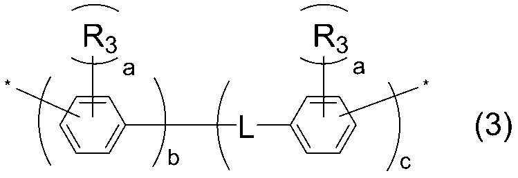
R3は、ハロゲン原子、又は炭素数1~5のアルキル基若しくはアルコキシ基を表し、該アルキル基若しくは該アルコキシ基の任意の水素原子はハロゲン原子で置換されていてもよく、任意の炭化水素基はtert-ブトキシカルボニル基で保護されたアミノ基で置換されていてもよい。
複数のaはそれぞれ独立して0~4の整数であり、bは1~2の整数であり、cは0~1の整数である。R3、aが複数存在する場合、それぞれ同一でも異なってもよい。)
-(CH2)p-、-O-(CH2)p-O-、
-(CH2)p-O-C(=O)-(CH2)q-、
-(CH2)p-N(R)-(CH2)q-(Rは水素原子、メチル基、又はtert-ブトキシカルボニル基を表す。)、
-(CH2)p-N(R)-C(=O)-N(R)-(CH2)q-(Rは水素原子、メチル基、又はtert-ブトキシカルボニル基を表す。2つのRは同一であっても異なっていてもよい。)、
-O-(CH2)p-O-(CH2)q-O-、
-(CH2)p’-O-C(=O)-(CH2)q-C(=O)-O-(CH2)r’-、
-(CH2)p’-C(=O)-O-(CH2)q-O-C(=O)-(CH2)r’-、
-(CH2)p’-O-C(=O)-Q-C(=O)-O-(CH2)q’-(Qはフェニレン基又はシクロヘキシレン基を表す。)、
-(CH2)p’-C(=O)-O-Q-O-C(=O)-(CH2)q’-(Qはフェニレン基又はシクロヘキシレン基を表す。)、が挙げられる。
ここにおいて、pは1~6の整数であり、好ましくは2~6の整数である。qは1~6の整数であり、2~6の整数がより好ましく、2~4の整数が更に好ましい。
p’、q’、r’は0~6の整数である。また、0≦p’+q’ ≦10を満たし、2≦p’+q+r’≦16を満たす。


本発明の液晶配向剤は、重合体(P)、及び必要に応じて使用されるその他の成分が、好ましくは適当な溶媒中に分散又は溶解してなる液状の組成物である。
なかでも、残留DC由来の残像を少なくする点から、重合体(B)がより好ましい。
上記その他の重合体は、一種を単独で使用してもよく、また二種以上を組み合わせて使用してもよい。その他の重合体の含有割合は、液晶配向剤中に含まれる重合体の合計100質量部に対して、90質量部以下が好ましく、10~90質量部がより好ましく、20~80質量部が更に好ましい。
上記重合体(B)の製造に用いられるテトラカルボン酸成分の具体例は、好ましい具体例を含めて、重合体(P)で例示した化合物と同様の化合物が挙げられる。重合体(B)の製造に用いられるテトラカルボン酸成分は、より好ましくは、ベンゼン環、シクロブタン環、シクロペンタン環及びシクロヘキサン環よりなる群から選ばれる少なくとも一種の部分構造を有するテトラカルボン酸二無水物又はこれらの誘導体(以下これらを特定のテトラカルボン酸成分(B)ともいう)を含むことがより好ましい。
また、上記特定のテトラカルボン酸成分(B)の使用量は、重合体(B)の製造に使用される全テトラカルボン酸成分1モルに対して、10モル%以上が好ましく、20モル%以上がより好ましく、50モル%以上がさらに好ましい。
上記特定ジアミン(b)を用いる場合、その使用量は、重合体(B)の製造に用いられる全ジアミン成分の10モル%以上が好ましく、20モル%以上がより好ましい。特定ジアミン(b)以外のジアミンを用いる場合、特定ジアミン(b)の使用量は、重合体(B)の製造に用いられる全ジアミン成分1モルに対して90モル%以下が好ましく、80モル%以下がより好ましい。
ポリアミック酸の製造は、ジアミン成分とテトラカルボン酸成分とを有機溶媒中で反応させることにより行われる。ポリアミック酸の製造反応に供されるテトラカルボン酸成分とジアミン成分との使用割合は、ジアミン成分のアミノ基1当量に対して、テトラカルボン酸成分の酸無水物基が0.5~2当量となる割合が好ましく、さらに好ましくは0.8~1.2当量である。通常の重縮合反応と同様に、このテトラカルボン酸成分の酸無水物基の当量が1当量に近いほど、生成するポリアミック酸の分子量は大きくなる。
ポリアミック酸の製造における反応温度は-20~150℃が好ましく、0~100℃がより好ましい。また、反応時間は0.1~24時間が好ましく、0.5~12時間がより好ましい。ポリアミック酸の製造は任意の濃度で行うことができるがポリアミック酸の濃度は好ましくは1~50質量%、より好ましくは5~30質量%である。反応初期は高濃度で行い、その後、溶媒を追加することもできる。
ポリアミック酸エステルは、例えば、[I]上記の方法で得られたポリアミック酸とエステル化剤とを反応させる方法、[II]テトラカルボン酸ジエステルとジアミンとを反応させる方法、[III]テトラカルボン酸ジエステルジハロゲン化物とジアミンとを反応させる方法、などの既知の方法によって得ることができる。
ポリイミドは、上記ポリアミック酸又はポリアミック酸エステルなどのポリイミド前駆体を閉環(イミド化)させることによりポリイミドを得ることができる。なお、本明細書でいうイミド化率とは、テトラカルボン酸二無水物又はその誘導体由来のイミド基とカルボキシ基(又はその誘導体)との合計量に占めるイミド基の割合のことである。イミド化率は、必ずしも100%である必要はなく、用途や目的に応じて任意に調整できる。
ポリイミド前駆体を溶液中で熱イミド化させる場合の温度は、好ましくは100~400℃であり、より好ましくは120~250℃であり、イミド化反応により生成する水を系外に除きながら行う方が好ましい。
本発明におけるポリイミド前駆体やポリイミドの末端の例としては、アミノ基、カルボキシ基、酸無水物基又は後述する末端封止剤に由来する基が挙げられる。アミノ基、カルボキシ基、酸無水物基は通常の縮合反応により得るか、又は以下の末端封止剤を用いて末端を封止することにより得ることができる。
末端封止剤の使用割合は、使用するジアミン成分の合計100モル部に対して、0.01~20モル部とすることが好ましく、0.01~10モル部とすることがより好ましい。
本発明の液晶配向剤は、上記重合体(P)、ならびに必要に応じて上記その他の重合体、および上記有機溶媒を含有する。
本発明の液晶配向剤に含まれる重合体の合計含有量は、形成させようとする塗膜の厚みの設定によっても適宜変更できるが、均一で欠陥のない塗膜を形成させるという点から1質量%以上が好ましく、溶液の保存安定性の点からは、10質量%以下が好ましい。特に好ましい重合体の合計含有量は、2~8質量%である。
本発明に用いられる重合体(P)の含有量は、液晶配向剤に含有される重合体の合計に対し、1~100質量%が好ましく、10~100質量%がより好ましく、20~100質量%が特に好ましい。
本発明の液晶配向剤は、上記重合体(P)、上記その他の重合体、及び上記有機溶媒に加えて、それ以外の成分(以下、添加剤成分ともいう。)を含有してもよい。かかる添加剤成分としては、例えば、オキシラニル基、オキセタニル基、ブロックイソシアネート基、オキサゾリン基、シクロカーボネート基、ヒドロキシ基及びアルコキシ基から選ばれる少なくとも1種の置換基を有する架橋性化合物、並びに重合性不飽和基を有する架橋性化合物からなる群から選ばれる少なくとも1種の架橋性化合物、官能性シラン化合物、金属キレート化合物、硬化促進剤、界面活性剤、酸化防止剤、増感剤、防腐剤、得られる液晶配向膜の誘電率や電気抵抗を調整するための化合物などが挙げられる。
架橋性化合物の含有量は液晶配向剤に含まれる重合体成分100質量部に対して0.1~30質量部であることが好ましく、より好ましくは0.1~20質量部である。
特に好ましい固形分濃度の範囲は、基板に液晶配向剤を塗布する際に用いる方法によって異なる。例えばスピンコート法を用いる場合には、固形分濃度が1.5~4.5質量%であることが特に好ましい。印刷法による場合には、固形分濃度を3~9質量%とし、それにより溶液粘度を12~50mPa・sとすることが特に好ましい。インクジェット法による場合には、固形分濃度を1~5質量%とし、それにより、溶液粘度を3~15mPa・sとすることが特に好ましい。重合体組成物を調製する際の温度は、好ましくは10~50℃であり、より好ましくは20~30℃である。
上記液晶配向剤を用いることにより、液晶配向膜を製造することができる。本発明の液晶表示素子は、上記液晶配向膜を具備するものである。本発明に係る液晶表示素子の動作モードは特に限定せず、例えばTN型、STN(Super Twisted Nematic)型、垂直配向型(VA-MVA型、VA-PVA型などを含む。)、IPS方式、FFS方式、光学補償ベンド型(OCB型)など種々の動作モードに適用することができる。本発明の液晶配向膜は、中でもIPS方式又はFFS方式等の水平配向型の液晶表示素子に好適な液晶配向膜である。
工程(1)は、本発明の液晶配向剤を基板上に塗布する工程である。工程(1)の具体例は以下のとおりである。
パターニングされた透明導電膜が設けられている基板の一面に、本発明の液晶配向剤を、例えばロールコーター法、スピンコート法、印刷法、インクジェット法などの適宜の塗布方法により塗布する。ここで基板としては、透明性の高い基板であれば特に限定されず、ガラス基板、窒化珪素基板とともに、アクリル基板やポリカーボネート基板等のプラスチック基板等を用いることもできる。また、反射型の液晶表示素子では、片側の基板のみにならば、シリコンウエハー等の不透明な物でも使用でき、この場合の電極にはアルミニウム等の光を反射する材料も使用できる。また、IPS方式又はFFS方式の液晶表示素子を製造する場合には、櫛歯型にパターニングされた透明導電膜又は金属膜からなる電極が設けられている基板と、電極が設けられていない対向基板とを用いる。
工程(2)は、基板上に塗布した液晶配向剤を焼成し、膜を形成する工程である。工程(2)の具体例は以下のとおりである。
工程(1)において液晶配向剤を基板上に塗布した後は、ホットプレート、熱循環型オーブン又はIR(赤外線)型オーブンなどの加熱手段により、溶媒を蒸発させたり、ポリアミック酸又はポリアミック酸エステルの熱イミド化を行ったりすることができる。本発明の液晶配向剤を塗布した後の乾燥、焼成工程は、任意の温度と時間を選択することができ、複数回行ってもよい。液晶配向剤の溶媒を低減する温度としては、例えば40~180℃で行うことができる。プロセスを短縮する観点で、40~150℃で行ってもよい。焼成時間としては特に限定されないが、1~10分又は、1~5分が挙げられる。ポリアミック酸又はポリアミック酸エステルの熱イミド化を行う場合には、上記工程の後、例えば150~300℃、又は150~250℃の温度範囲で焼成する工程を追加してもよい。焼成時間としては特に限定されないが、5~40分、又は、5~30分の焼成時間が挙げられる。
焼成後の膜状物の膜厚は、薄すぎると液晶表示素子の信頼性が低下する場合があるので、5~300nmが好ましく、10~200nmがより好ましい。
工程(3)は、場合により、工程(2)で得られた膜に配向処理する工程である。即ち、IPS方式又はFFS方式等の水平配向型の液晶表示素子では該塗膜に対し配向能付与処理を行う。一方、VA方式又はPSA方式等の垂直配向型の液晶表示素子では、形成した塗膜をそのまま液晶配向膜として使用することができるが、該塗膜に対し配向能付与処理を施してもよい。液晶配向膜の配向処理方法としては、ラビング処理法、光配向処理法が挙げられる。光配向処理法としては、上記膜状物の表面に、一定方向に偏光された放射線を照射し、場合により、好ましくは、150~250℃の温度で加熱処理を行い、液晶配向性(液晶配向能ともいう)を付与する方法が挙げられる。放射線としては、100~800nmの波長を有する紫外線又は可視光線を用いることができる。なかでも、好ましくは100~400nm、より好ましくは、200~400nmの波長を有する紫外線である。
上記ラビング処理法としては、塗膜を例えばナイロン、レーヨン、コットンなどの繊維からなる布を巻き付けたロールで一定方向に擦る処理が挙げられる。
上記光配向処理法において、放射線が偏光である場合、直線偏光であっても部分偏光であってもよい。また、用いる放射線が直線偏光又は部分偏光である場合には、照射は基板面に垂直の方向から行ってもよく、斜め方向から行ってもよく、又はこれらを組み合わせて行ってもよい。非偏光の放射線を照射する場合には、照射の方向は斜め方向とすることが好ましい。
上記のようにして液晶配向膜が形成された基板を2枚準備し、対向配置した2枚の基板間に液晶を配置する。具体的には以下の2つの方法が挙げられる。
第一の方法は、先ず、それぞれの液晶配向膜が対向するように間隙(セルギャップ)を介して2枚の基板を対向配置する。次いで、2枚の基板の周辺部をシール剤を用いて貼り合わせ、基板表面及びシール剤により区画されたセルギャップ内に液晶組成物を注入充填して膜面に接触した後、注入孔を封止する。
なお、塗膜に対してラビング処理を行った場合には、2枚の基板は、各塗膜におけるラビング方向が互いに所定の角度、例えば直交又は逆平行となるように対向配置される。
シール剤としては、例えば硬化剤及びスペーサーとしての酸化アルミニウム球を含有するエポキシ樹脂等を用いることができる。
液晶組成物は、ネマチック相を呈する液晶組成物、スメクチック相を呈する液晶組成物、又はコレステリック相を呈する液晶組成物であってもよい。
また、上記液晶組成物は、液晶配向性を向上させる観点から、添加物をさらに含有してもよい。このような添加物は、重合性基を有する化合物などの光重合性モノマー;光学活性な化合物(例:メルク(株)社製のS-811など);酸化防止剤;紫外線吸収剤;色素;消泡剤;重合開始剤;又は重合禁止剤などが挙げられる。
ポジ型液晶としては、メルク社製のZLI-2293、ZLI-4792、MLC-2003、MLC-2041、又はMLC-7081などが挙げられる。
ネガ型液晶としては、例えばメルク社製のMLC-6608、MLC-6609、MLC-6610、又はMLC-7026-100などが挙げられる。
また、重合性基を有する化合物を含有する液晶として、メルク社製のMLC-3023が挙げられる。
また、本発明の液晶配向剤は、電極を備えた一対の基板の間に液晶層を有してなり、上記一対の基板の間に活性エネルギー線及び熱の少なくとも一方により重合する重合性基を含む液晶配向膜を配置し、電極間に電圧を印加する工程(以下、本工程を工程(6)ともいう。)を経て製造される液晶表示素子(SC-PVA方式の液晶表示素子)にも好ましく用いられる。
なお、FFS方式において使用される櫛歯電極基板であるFFS基板は、基材と、基材上に形成された面電極と、面電極上に形成された絶縁膜と、絶縁膜上に形成され、櫛歯状に配置された複数の線状電極と、絶縁膜上に線状電極を覆うように形成された液晶配向膜とを有する。
図1に例示する横電界液晶表示素子1においては、液晶配向膜2cを具備する櫛歯電極基板2と液晶配向膜4aを具備する対向基板4との間に、液晶3が挟持されている。櫛歯電極基板2は、基材2aと、基材2a上に形成され、櫛歯状に配置された複数の線状電極2bと、基材2a上に線状電極2bを覆うように形成された液晶配向膜2cとを有している。対向基板4は、基材4bと、基材4b上に形成された液晶配向膜4aとを有している。液晶配向膜2cは、例えば、本発明の液晶配向膜である。液晶配向膜4cも同様に本発明の液晶配向膜である。
この横電界液晶表示素子1においては、線状電極2bに電圧が印加されると、電気力線Lで示すように線状電極2b間で電界が発生する。
図2に例示する横電界液晶表示素子1においては、液晶配向膜2hを具備する櫛歯電極基板2と液晶配向膜4aを具備する対向基板4との間に、液晶3が挟持されている。櫛歯電極基板2は、基材2dと、基材2d上に形成された面電極2eと、面電極2e上に形成された絶縁膜2fと、絶縁膜2f上に形成され、櫛歯状に配置された複数の線状電極2gと、絶縁膜2f上に線状電極2gを覆うように形成された液晶配向膜2hとを有している。対向基板4は、基材4bと、基材4b上に形成された液晶配向膜4aとを有している。液晶配向膜2hは、例えば、本発明の液晶配向膜である。液晶配向膜4aも同様に本発明の液晶配向膜である。
この横電界液晶表示素子1においては、面電極2eおよび線状電極2gに電圧が印加されると、電気力線Lで示すように面電極2eおよび線状電極2g間で電界が発生する。
(有機溶媒)
NMP:N-メチル-2-ピロリドン
GBL:γ-ブチロラクトン
BCS:ブチルセロソルブ
(テトラカルボン酸二無水物)
CA-1:下記式(CA-1)で表される化合物
尚、上記式(CA-1)で表される化合物は、上記特定の芳香族テトラカルボン酸成分(p)の範囲に含まれる化合物である。
(ジアミン)
DA-1~DA-3:それぞれ、下記式(DA-1)~(DA-3)で表される化合物
尚、上記式(DA-1)で表される化合物は、上記特定ジアミン(p)の範囲に含まれる化合物であり、上記式(DA-2)~(DA-3)で表される化合物は、その他のジアミンの範囲に含まれる化合物である。
DA-1は、WO2015/030071号に記載された合成法に従って合成した。

E型粘度計TVE-22H(東機産業社製)を用い、サンプル量1.1mL、コーンロータTE-1(1°34’、R24)を用いて、温度25℃で測定した。
<分子量の測定>
下記の常温GPC(ゲル浸透クロマトグラフィー)装置によって測定し、ポリエチレングリコール、ポリエチレンオキサイド換算値としてMn及びMwを算出した。
GPC装置:GPC-101(昭和電工社製)、カラム:GPC KD-803、GPC KD-805(昭和電工社製)の直列、カラム温度:50℃、溶離液:N,N-ジメチルホルムアミド(添加剤として、臭化リチウム一水和物(LiBr・H2O)が30mmol/L、リン酸・無水結晶(o-リン酸)が30mmol/L、テトラヒドロフラン(THF)が10mL/L)、流速:1.0mL/分
検量線作成用標準サンプル:TSK 標準ポリエチレンオキサイド(分子量;約900,000、150,000、100,000及び30,000)(東ソー社製)及びポリエチレングリコール(分子量;約12,000、4,000及び1,000)(ポリマーラボラトリー社製)。
<合成例1>
撹拌装置付きの50mL四つ口フラスコに、DA-1(2.30g、14.0mmol)及びNMP(17.0g)を加えて、室温で撹拌して溶解させた。その後、CA-1(3.79g、12.9mmol)及びNMP(27.8g)を加えて、室温で24時間撹拌することで、固形分濃度12質量%のポリアミック酸溶液(PAA1)(粘度:70mPa・s)を得た。このポリアミック酸のMnは3,500、Mwは6,300であった。
<合成例2>
撹拌装置付きの50mL四つ口フラスコに、DA-2(1.50g、10.00mmol)及びNMP(11.3g)を加えて、室温で撹拌して溶解させた。その後、CA-1(2.93g、9.95mmol)及びNMP(20.0g)を加えて、50℃で24時間撹拌することで、固形分濃度12質量%のポリアミック酸溶液(PAA2)(粘度:302mPa・s)を得た。このポリアミック酸のMnは5,600、Mwは11,900であった。
<合成例3>
撹拌装置付きの50mL四つ口フラスコに、DA-3(2.04g、15.0mmol)及びNMP(15.1g)を加えて、室温で撹拌して溶解させた。その後、CA-1(4.06g、13.8mmol)及びNMP(29.8g)を加えて、室温で3時間撹拌することで、固形分濃度12質量%のポリアミック酸溶液(PAA3)(粘度:356mPa・s)を得た。このポリアミック酸のMnは5,200、Mwは13,800であった。
合成例1で得られたポリアミック酸溶液(PAA1)をNMP、GBL及びBCSにより希釈し、室温で2時間撹拌することで、重合体固形分と各溶媒の質量比(重合体固形分:NMP:GBL:BCS)が4:46:30:20となる液晶配向剤(AL-1)を得た。この液晶配向剤に、濁りや析出などの異常は見られず、均一な溶液であることが確認された。
<比較例1~2>
PAA1の代わりにPAA2、PAA3を用いた以外は実施例1と同様の方法でそれぞれ液晶配向剤AL-R1、AL-R2を調製した。
実施例及び比較例で得られた各液晶配向剤の組成を表1に示す。表1中、組成比の括弧内の数値は、液晶配向剤の構成成分100質量部に対する、各構成成分の割合(質量部)を表す。

フリンジフィールドスィッチング(Fringe Field Switching:FFS)モード液晶表示素子の構成を備えた液晶セルを作製した。
始めに、電極付きの基板を準備した。基板は、30mm×35mmの大きさで、厚さが0.7mmのガラス基板を用いた。基板上には第1層目として対向電極を構成する、ベタ状のパターンを備えたITO電極が形成され、第1層目の対向電極の上には第2層目として、CVD(化学蒸着)法により成膜されたSiN(窒化珪素)膜が形成されていた。第2層目のSiN膜は、層間絶縁膜として機能する膜厚は300nmのものを用いた。第2層目のSiN膜の上には、第3層目としてITO膜をパターニングして形成された櫛歯状の画素電極が配置され、第1画素及び第2画素の2つの画素が形成されており、各画素のサイズは、縦10mmで横約5mmであった。このとき、第1層目の対向電極と第3層目の画素電極とは、第2層目のSiN膜の作用により電気的に絶縁されていた。
第3層目の画素電極は、中央部分が内角160°で屈曲した幅3μmの電極要素が6μmの間隔を開けて平行になるように複数配列された櫛歯形状を有しており、1つの画素は、複数の電極要素の屈曲部を結ぶ線を境にそれぞれ第1領域と第2領域を有していた。
各画素の第1領域と第2領域とを比較すると、それらを構成する画素電極の電極要素の形成方向が異なるものとなっていた。すなわち、上記複数の電極要素の屈曲部を結ぶ線を基準とした場合、画素の第1領域では画素電極の電極要素が時計回りに80°の角度をなすように形成され、画素の第2領域では画素電極の電極要素が反時計回りに80°の角度をなすように形成されていた。すなわち、各画素の第1領域と第2領域とでは、画素電極と対向電極との間の電圧印加によって誘起される液晶の、基板面内での回転動作(インプレーン・スイッチング)の方向が互いに逆方向となるように構成されていた。
次に、上記で得られた液晶配向剤を孔径1.0μmのフィルターで濾過した後、上記で準備した電極付き基板(第1のガラス基板)の表面にスピンコート法にて塗布した。次いで、80℃のホットプレート上で2分間乾燥させた後、230℃の熱風循環式オーブンで20分間焼成を行い、厚み60nmのポリイミド膜を得た。このポリイミド膜をレーヨン布(Hyperflex社製、HY-5318)でラビング配向処理(ローラー直径:120mm、ローラー回転数:1000rpm、移動速度:30mm/sec、押し込み長:0.4mm、ラビング方向:第3層目の画素電極の上記複数の電極要素の屈曲部を結ぶ方向に対して180℃の方向)した。その後、純水中にて1分間超音波照射をして洗浄を行い、エアブローにて水滴を除去した後、80℃のオーブンで15分間乾燥して、液晶配向膜付き基板を得た。また、対向基板として、裏面にITO電極が形成されている、高さ4μmの柱状スペーサーを有するガラス基板にも、上記と同様に処理して、配向処理が施された液晶配向膜付き基板を得た。これら2枚の液晶配向膜付き基板を1組とし、片方の基板上に液晶注入口を残した形でシール剤(三井化学社製 XN-1500T)を印刷し、もう1枚の基板を、液晶配向膜面が向き合い、ラビング方向が逆平行になるようにして貼り合わせた。その後、150℃で60分間の加熱処理を行い、シール剤を硬化させて、セルギャップが4μmの空セルを作製した。この空セルに減圧注入法によって、ネガ型液晶MLC-7026-100(メルク社製)を注入し、注入口を封止して、FFS方式の液晶セルを得た。その後、得られた液晶セルを120℃で1時間加熱し、23℃で一晩放置してから評価に使用した。
上記で作製した液晶セルを、偏光軸が直交するように配置された2枚の偏光板の間に設置し、画素電極と対向電極とを短絡して同電位にした状態で、2枚の偏光板の下からLEDバックライトを照射しておき、2枚の偏光板の上で測定するLEDバックライト透過光の輝度が最小となるように、液晶セルの角度を調節した。次に、この液晶セルに周波数30Hzの交流電圧を印加しながらV-Tカーブ(電圧-透過率曲線)を測定し、相対透過率が23%となる交流電圧を駆動電圧として算出した。
絶対値測定では、周波数30Hzの交流電圧を印加して液晶セルを駆動させ、3分毎にセル内透過率が100%となる交流駆動を行い、点灯直後のV-F(電圧-フリッカ曲線)カーブを測定し、フリッカが最小となるオフセット電圧を算出した。その後3分毎に最小オフセット電圧値変化量を測定し、点灯直後から30分までに変化した際の最大電圧値を算出した。その際、最大オフセット電圧の変化量が20mVを超える場合「不良」と定義し評価した。また最大オフセット電圧の変化量が20mVを越えない場合には、「良好」と定義し評価した。
液晶セルの角度調節及び相対透過率が23%となる交流電圧(以下、交流電圧(VB)ともいう。)の算出は、上記蓄積電荷の絶対値測定と同様の手順で行った。
次に、交流電圧(VB)を印加して液晶セルを駆動させながら、同時に1Vの直流電圧を印加し、30分間駆動させた。その後、直流電圧の印加のみを停止し、交流電圧のみでさらに15分駆動した。
直流電圧の印加を停止した時点から10分間が経過するまでに、相対透過率が25%以下に緩和した場合は「良好」とし、相対透過率が25%以下に低下するまでに10分間以上を要した場合は「不良」と定義して評価を行った。結果を表2に示す。
なお、上述した方法に従う蓄積電荷の緩和速度評価は、室温条件下で行った。
上記で作成した液晶セルを、偏光軸が直交するように配置された2枚の偏光板の間に設置した。
光応答性評価では、測定開始と同時に2枚の偏光板の下からLEDバックライトを照射し、相対透過率が23%となる周波数30Hzの交流電圧を印加して液晶セルを30分間駆動させた際のフリッカー振幅を追跡した。フリッカー振幅は、2枚の偏光板及びその間の液晶セルを通過したLEDバックライトの透過光を、フォトダイオード及びI-V変換アンプを介して接続されたデータ収集/データロガースイッチユニット34410A(KEYSIGHT社製)で読み取った。フリッカーレベルは以下の数式で算出した。
フリッカーレベル(%)={フリッカー振幅/(2×z)}×100
上記式中、zは相対透過率が23%となる周波数30Hzの交流電圧で駆動した際の輝度をデータ収集/データロガースイッチユニット34410Aで読み取った値である。
光応答性の評価は、LEDバックライトの点灯及び交流電圧の印加を開始した時点から30分間が経過するまでに、フリッカーレベルの変化量が3%未満を維持した場合は「良」、3%以上に達した場合には「不良」と定義して評価した。結果を表2に示す。
なお、上述した方法に従う光応答性の評価は、室温条件下で行った。
(実施例1及び比較例1~2)
上記実施例1及び比較例1~2で得られた液晶配向剤(AL-1)及び(AL-R1)~(AL-R2)を使用して得られた液晶表示素子に関しての特性評価結果を表2に示す。

2 櫛歯電極基板
2a 基材
2b 線状電極
2c 液晶配向膜
2d 基材
2e 面電極
2f 絶縁膜
2g 線状電極
2h 液晶配向膜
3 液晶
4 対向基板
4a 液晶配向膜
4b 基材
L 電気力線
Claims (11)
- 下記式(1)で表されるテトラカルボン酸二無水物及びその誘導体からなる群から選ばれる少なくとも1種類を含むテトラカルボン酸成分と、下記式(2)で表されるジアミンを含むジアミン成分を用いて得られるポリイミド前駆体及び該ポリイミド前駆体のイミド化物であるポリイミドからなる群から選ばれる少なくとも1種の重合体(P)を含有する液晶配向剤。

- 前記Y2が、下記式(3)で表される構造である、請求項1に記載の液晶配向剤。
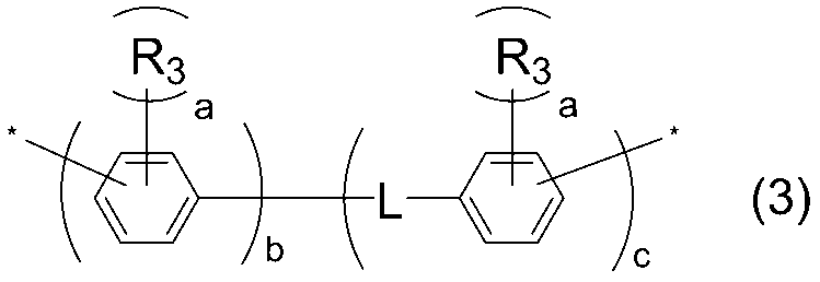
R3は、ハロゲン原子、又は炭素数1~5のアルキル基若しくはアルコキシ基を表し、該アルキル基若しくは該アルコキシ基の任意の水素原子はハロゲン原子で置換されていてもよく、任意の炭化水素基はtert-ブトキシカルボニル基で保護されたアミノ基で置換されていてもよい。
複数のaはそれぞれ独立して0~4の整数であり、bは1~2の整数であり、cは0~1の整数である。R3、aが複数存在する場合、それぞれ同一でも異なってもよい。*は結合手を表す。) - 前記Lが、-O-、-O-C(=O)-、-C(=O)-、-N(R)-(Rは水素原子、メチル基、又はtert-ブトキシカルボニル基を表す。)、-N(R)-C(=O)-(Rは水素原子、メチル基、又はtert-ブトキシカルボニル基を表す。)、-N(R)-C(=O)-N(R)-(Rは水素原子、メチル基、又はtert-ブトキシカルボニル基を表す。2つのRは同一であっても異なっていてもよい。)、-(CH2)p-、-O-(CH2)p-O-、
-(CH2)p-O-C(=O)-(CH2)q-、
-(CH2)p-N(R)-(CH2)q-(Rは水素原子、メチル基、又はtert-ブトキシカルボニル基を表す。)、
-(CH2)p-N(R)-C(=O)-N(R)-(CH2)q-(Rは水素原子、メチル基、又はtert-ブトキシカルボニル基を表す。2つのRは同一であっても異なっていてもよい。)、
-O-(CH2)p-O-(CH2)q-O-、
-(CH2)p’-O-C(=O)-(CH2)q-C(=O)-O-(CH2)r’-、
-(CH2)p’-C(=O)-O-(CH2)q-O-C(=O)-(CH2)r’-、
-(CH2)p’-O-C(=O)-Q-C(=O)-O-(CH2)q’-(Qはフェニレン基又はシクロヘキシレン基を表す。)、
又は
-(CH2)p’-C(=O)-O-Q-O-C(=O)-(CH2)q’-(Qはフェニレン基又はシクロヘキシレン基を表す。)のいずれかから選ばれる、請求項2に記載の液晶配向剤。
(pは1~6の整数である。qは1~6の整数である。p’、q’、r’はそれぞれ独立して0~6の整数である。また、0≦p’+q’ ≦10を満たし、2≦p’+q+r’≦16を満たす。) - 前記式(2)で表されるジアミンが、下記式(d2-1)~(d2-3)のいずれかで表されるジアミンである、請求項1~3のいずれか一項に記載の液晶配向剤。

- 前記式(2)で表されるジアミンの使用量が、重合体(P)の製造に使用されるジアミン成分1モルに対して、5モル%以上である、請求項1~3のいずれか一項に記載の液晶配向剤。
- 前記式(1)におけるXaが、下記式(Xa-1)および(Xa-2)から選ばれる構造のいずれかである、請求項1~5のいずれか一項に記載の液晶配向剤。
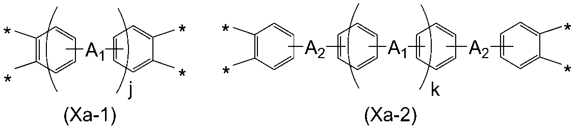
- 上記式(Xa-1)および(Xa-2)が、下記式(Xa-3)~(Xa-18)から選ばれる構造のいずれかである、請求項6に記載の液晶配向剤。


- 前記式(1)で表されるテトラカルボン酸二無水物及びその誘導体の使用量が、重合体(P)の製造に使用されるテトラカルボン酸成分1モルに対して、10モル%以上である、請求項1~7のいずれか一項に記載の液晶配向剤。
- 請求項1~8のいずれか一項に記載の液晶配向剤から得られる液晶配向膜。
- 請求項9の液晶配向膜を具備する液晶表示素子。
- 下記の工程(1)~(3)を含む、液晶表示素子の製造方法。
工程(1):請求項1~8のいずれか一項に記載の液晶配向剤を基板上に塗布する工程
工程(2):塗布した前記液晶配向剤を焼成し、膜を得る工程
工程(3):工程(2)で得られた前記膜に配向処理する工程
Priority Applications (3)
| Application Number | Priority Date | Filing Date | Title |
|---|---|---|---|
| JP2024517283A JPWO2023210532A1 (ja) | 2022-04-27 | 2023-04-21 | |
| KR1020247036393A KR20250006072A (ko) | 2022-04-27 | 2023-04-21 | 액정 배향제, 액정 배향막 및 액정 표시 소자 |
| CN202380036389.2A CN119096187A (zh) | 2022-04-27 | 2023-04-21 | 液晶取向剂、液晶取向膜以及液晶显示元件 |
Applications Claiming Priority (2)
| Application Number | Priority Date | Filing Date | Title |
|---|---|---|---|
| JP2022-073221 | 2022-04-27 | ||
| JP2022073221 | 2022-04-27 |
Publications (1)
| Publication Number | Publication Date |
|---|---|
| WO2023210532A1 true WO2023210532A1 (ja) | 2023-11-02 |
Family
ID=88518865
Family Applications (1)
| Application Number | Title | Priority Date | Filing Date |
|---|---|---|---|
| PCT/JP2023/015956 Ceased WO2023210532A1 (ja) | 2022-04-27 | 2023-04-21 | 液晶配向剤、液晶配向膜及び液晶表示素子 |
Country Status (5)
| Country | Link |
|---|---|
| JP (1) | JPWO2023210532A1 (ja) |
| KR (1) | KR20250006072A (ja) |
| CN (1) | CN119096187A (ja) |
| TW (1) | TW202405141A (ja) |
| WO (1) | WO2023210532A1 (ja) |
Citations (3)
| Publication number | Priority date | Publication date | Assignee | Title |
|---|---|---|---|---|
| WO2008078796A1 (ja) * | 2006-12-27 | 2008-07-03 | Nissan Chemical Industries, Ltd. | 液晶配向剤、それを用いた液晶配向膜及び液晶表示素子 |
| CN112225675A (zh) * | 2020-09-22 | 2021-01-15 | 江苏三月科技股份有限公司 | 一种芳胺类化合物及其制备的液晶取向剂、液晶取向膜和液晶显示元件 |
| CN114085680A (zh) * | 2021-12-02 | 2022-02-25 | 深圳市道尔顿电子材料有限公司 | 一种适用于摩擦型ips的双层型聚酰亚胺液晶取向剂及其制备方法 |
Family Cites Families (1)
| Publication number | Priority date | Publication date | Assignee | Title |
|---|---|---|---|---|
| JP2019101196A (ja) | 2017-11-30 | 2019-06-24 | 日産化学株式会社 | 液晶配向剤、液晶配向膜、及び液晶表示素子 |
-
2023
- 2023-04-21 WO PCT/JP2023/015956 patent/WO2023210532A1/ja not_active Ceased
- 2023-04-21 CN CN202380036389.2A patent/CN119096187A/zh active Pending
- 2023-04-21 JP JP2024517283A patent/JPWO2023210532A1/ja active Pending
- 2023-04-21 KR KR1020247036393A patent/KR20250006072A/ko active Pending
- 2023-04-25 TW TW112115387A patent/TW202405141A/zh unknown
Patent Citations (3)
| Publication number | Priority date | Publication date | Assignee | Title |
|---|---|---|---|---|
| WO2008078796A1 (ja) * | 2006-12-27 | 2008-07-03 | Nissan Chemical Industries, Ltd. | 液晶配向剤、それを用いた液晶配向膜及び液晶表示素子 |
| CN112225675A (zh) * | 2020-09-22 | 2021-01-15 | 江苏三月科技股份有限公司 | 一种芳胺类化合物及其制备的液晶取向剂、液晶取向膜和液晶显示元件 |
| CN114085680A (zh) * | 2021-12-02 | 2022-02-25 | 深圳市道尔顿电子材料有限公司 | 一种适用于摩擦型ips的双层型聚酰亚胺液晶取向剂及其制备方法 |
Also Published As
| Publication number | Publication date |
|---|---|
| KR20250006072A (ko) | 2025-01-10 |
| TW202405141A (zh) | 2024-02-01 |
| CN119096187A (zh) | 2024-12-06 |
| JPWO2023210532A1 (ja) | 2023-11-02 |
Similar Documents
| Publication | Publication Date | Title |
|---|---|---|
| JP7505643B2 (ja) | 液晶配向剤、液晶配向膜及び液晶表示素子 | |
| JP7831478B2 (ja) | 液晶配向剤、液晶配向膜及び液晶表示素子 | |
| JP7351435B2 (ja) | 液晶配向剤、液晶配向膜及び液晶表示素子 | |
| JP7848806B2 (ja) | 液晶配向剤、液晶配向膜、及び液晶表示素子 | |
| WO2023219112A1 (ja) | 新規なジアミン化合物、該ジアミンを用いて得られる重合体、液晶配向剤、液晶配向膜、及び液晶表示素子 | |
| WO2023074570A1 (ja) | 液晶配向剤、液晶配向膜及び液晶表示素子 | |
| WO2023074392A1 (ja) | 液晶配向剤、液晶配向膜及び液晶表示素子 | |
| WO2024157869A1 (ja) | 液晶配向剤、液晶配向膜及び液晶表示素子 | |
| WO2023286733A1 (ja) | 液晶配向剤、液晶配向膜、液晶表示素子の製造方法及び液晶表示素子 | |
| KR20240023525A (ko) | 액정 배향제, 액정 배향막 및 액정 표시 소자 | |
| KR102902780B1 (ko) | 액정 배향제, 액정 배향막 및 액정 표시 소자 | |
| JP7860544B2 (ja) | 液晶配向剤、液晶配向膜及び液晶表示素子 | |
| KR20250006072A (ko) | 액정 배향제, 액정 배향막 및 액정 표시 소자 | |
| JP7831480B2 (ja) | 液晶配向剤、液晶配向膜、液晶表示素子、ジアミン及び重合体 | |
| WO2025105279A1 (ja) | 液晶配向剤、液晶配向膜及び液晶表示素子 | |
| WO2025105278A1 (ja) | 液晶配向剤、液晶配向膜及び液晶表示素子 | |
| WO2024122359A1 (ja) | 液晶配向剤、液晶配向膜及び液晶表示素子 | |
| WO2025089307A1 (ja) | 液晶配向剤、液晶配向膜及び液晶表示素子 | |
| WO2025079520A1 (ja) | 液晶配向剤、液晶配向膜、及び液晶表示素子 | |
| WO2025079517A1 (ja) | 液晶配向剤、液晶配向膜及び液晶表示素子 | |
| WO2025121189A1 (ja) | 液晶配向剤、液晶配向膜及び液晶表示素子 | |
| WO2025121249A1 (ja) | 液晶配向剤、液晶配向膜及び液晶表示素子 | |
| KR20260066157A (ko) | 액정 배향제, 액정 배향막 및 액정 표시 소자 | |
| WO2025205803A1 (ja) | 液晶配向剤、液晶配向膜及び液晶表示素子 | |
| WO2025079518A1 (ja) | 液晶配向剤、液晶配向膜及び液晶表示素子 |
Legal Events
| Date | Code | Title | Description |
|---|---|---|---|
| 121 | Ep: the epo has been informed by wipo that ep was designated in this application |
Ref document number: 23796274 Country of ref document: EP Kind code of ref document: A1 |
|
| ENP | Entry into the national phase |
Ref document number: 2024517283 Country of ref document: JP Kind code of ref document: A |
|
| WWE | Wipo information: entry into national phase |
Ref document number: 202380036389.2 Country of ref document: CN |
|
| NENP | Non-entry into the national phase |
Ref country code: DE |
|
| 122 | Ep: pct application non-entry in european phase |
Ref document number: 23796274 Country of ref document: EP Kind code of ref document: A1 |