WO2023210459A1 - 電鋳管の製造方法及び電鋳装置 - Google Patents
電鋳管の製造方法及び電鋳装置 Download PDFInfo
- Publication number
- WO2023210459A1 WO2023210459A1 PCT/JP2023/015562 JP2023015562W WO2023210459A1 WO 2023210459 A1 WO2023210459 A1 WO 2023210459A1 JP 2023015562 W JP2023015562 W JP 2023015562W WO 2023210459 A1 WO2023210459 A1 WO 2023210459A1
- Authority
- WO
- WIPO (PCT)
- Prior art keywords
- wire
- anode
- around
- electroforming
- viewed
- Prior art date
- Legal status (The legal status is an assumption and is not a legal conclusion. Google has not performed a legal analysis and makes no representation as to the accuracy of the status listed.)
- Ceased
Links
Images



Classifications
-
- C—CHEMISTRY; METALLURGY
- C25—ELECTROLYTIC OR ELECTROPHORETIC PROCESSES; APPARATUS THEREFOR
- C25D—PROCESSES FOR THE ELECTROLYTIC OR ELECTROPHORETIC PRODUCTION OF COATINGS; ELECTROFORMING; APPARATUS THEREFOR
- C25D1/00—Electroforming
-
- C—CHEMISTRY; METALLURGY
- C25—ELECTROLYTIC OR ELECTROPHORETIC PROCESSES; APPARATUS THEREFOR
- C25D—PROCESSES FOR THE ELECTROLYTIC OR ELECTROPHORETIC PRODUCTION OF COATINGS; ELECTROFORMING; APPARATUS THEREFOR
- C25D1/00—Electroforming
- C25D1/02—Tubes; Rings; Hollow bodies
Definitions
- the present invention relates to a method for manufacturing an electroformed pipe and an electroforming device.
- Electroformed tubes are used, for example, as probes for testing objects to be tested, such as integrated circuits (ICs).
- ICs integrated circuits
- Patent Document 1 a stainless steel wire acting as a cathode and an anode are impregnated with an electroforming solution, and the wire is rotated around the axial direction of the wire.
- An electroformed layer may be formed on the wire with the same part of the outer peripheral surface of the wire facing the anode without moving the wire and the anode.
- the thickness of the electroformed layer in the portion of the wire that faces the anode may be thicker than the thickness of the electroformed layer in other portions of the wire.
- the wire may be rotated around the axial direction of the wire. However, even in this case, it may be difficult to uniformly form the electroformed layer around the wire.
- An example of the object of the present invention is to uniformly form an electroformed layer around a wire.
- Other objects of the invention will become apparent from the description herein.
- One aspect of the present invention is A method for manufacturing an electroformed tube, comprising the step of moving at least one of an anode and at least one wire acting as a cathode around the other of the anode and the at least one wire.
- One aspect of the present invention is an anode; a first drive unit that moves at least one of the anode and at least one wire acting as a cathode around the other of the anode and the at least one wire; This is an electroforming device equipped with.
- the electroformed layer can be uniformly formed around the wire.
- FIG. 1 is a diagram showing an electroforming apparatus according to an embodiment.
- 7 is a diagram showing an electroforming apparatus according to modification example 1.
- FIG. 7 is a diagram for explaining a method for manufacturing an electroformed pipe according to a second modification.
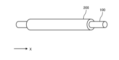
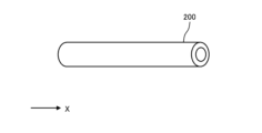
- FIGS. 1 to 4 are diagrams for explaining a method for manufacturing an electroformed pipe according to an embodiment.
- the electroformed tube according to the embodiment can be used, for example, as a probe for testing an object to be tested such as an IC.
- the method for manufacturing an electroformed pipe according to the embodiment will simply be referred to as the method according to the embodiment.
- the X direction will be defined.
- the X direction indicates the axial direction of the wire rod 100, which will be described later.
- a wire 100 is prepared.
- the wire 100 has electrical conductivity.
- the wire 100 is made of stainless steel, for example.
- the wire 100 may be made of a material different from stainless steel.
- the wire 100 may be made of iron, copper, gold, silver, brass, nickel, aluminum, carbon, plastic, resin, or the like.
- the wire rod 100 extends substantially parallel to the X direction.
- a cross section of the wire 100 perpendicular to the X direction has a substantially circular shape.
- the diameter of the wire 100 perpendicular to the X direction is, for example, 10 ⁇ m or more and 500 ⁇ m or less.
- the outer peripheral surface of the wire 100 may be covered with metal when viewed from the X direction.
- an electroformed layer 200 is formed around the outer peripheral surface of the wire 100 when viewed from the X direction, excluding both ends of the wire 100 in the X direction.
- the electroformed layer 200 is made of, for example, metals such as nickel, gold, copper, palladium, rhodium, platinum, and silver, or alloys thereof.
- the electroformed layer 200 is formed using an electroforming apparatus 1 that will be described later.
- the thickness of the electroformed layer 200 perpendicular to the X direction is, for example, 5 ⁇ m or more and 100 ⁇ m or less.
- the wire 100 is removed from the electroformed layer 200.
- the wire 100 can be removed from the electroformed layer 200 by pulling the wire 100 from the electroformed layer 200 in the X direction.
- the method for removing the wire 100 from the electroformed layer 200 is not limited to this example.
- the electroformed layer 200 is cut into a plurality of pieces P. Each cut out piece P becomes an electroformed pipe. In this way, the electroformed tube according to the embodiment is manufactured.
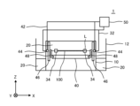
- FIG. 5 is a diagram showing the electroforming apparatus 1 according to the embodiment.
- an X direction, a Y direction, and a Z direction are defined.
- the Z direction is a direction parallel to the vertical direction.
- the X direction is one of the horizontal directions perpendicular to the Z direction.
- the Y direction is one of the horizontal directions perpendicular to the Z direction and the X direction.
- description will be given assuming that the X direction is the left-right direction, the Y direction is the front-back direction, and the Z direction is the up-down direction.
- the directions pointed by the arrows in the X direction and the Z direction are defined as the right direction and the upward direction, respectively.
- a white circle with an X indicating the Y direction indicates the front direction from the back of the page to the front.
- the electroforming apparatus 1 includes an electroforming tank 10, an outer tank 12, cathode wiring 32, a pair of cathode motors 34, an anode 40, anode wiring 42, a pair of anode motors 44, a pair of fixed supports 46, and a pair
- the rotating support body 48 and the power source 50 are provided.
- the electroforming tank 10 is housed inside the outer tank 12.
- the upper end of the electroforming tank 10 and the upper end of the outer tank 12 are open upward.
- the electroforming bath 10 is always supplied with the electroforming liquid 20 .
- the electroforming liquid 20 overflows from the upper part of the electroforming tank 10.
- the electroforming liquid 20 overflowing from the electroforming tank 10 flows into the outer tank 12.
- the electroforming liquid 20 overflowing from the electroforming tank 10 and flowing into the outer tank 12 is supplied to the electroforming tank 10 again by a filtering device (not shown). In this way, during operation of the electroforming apparatus 1, the electroforming liquid 20 circulates through the electroforming tank 10, the outer tank 12, and the filtration device.
- the type of electroforming liquid 20 is determined by predetermined conditions such as the material of the electroforming layer 200 formed on the outer peripheral surface of the wire 100.
- the electroforming solution 20 includes, for example, a nickel sulfate solution or a nickel sulfamate solution, and optionally includes a brightening agent and a bit prevention agent.
- a wire rod 100 is impregnated in the electroforming liquid 20 in the electroforming tank 10.
- the longitudinal direction of the wire rod 100 is approximately parallel to the X direction. Both ends of the wire 100 in the X direction are electrically connected to the power source 50 via the cathode wiring 32. Thereby, the wire 100 is operating as a cathode.
- the virtual line L is shown as a broken line for explanation.
- the virtual line L passes through the center of the wire 100 substantially parallel to the X direction. That is, the virtual line L indicates the axial direction of the wire 100.
- the wire 100 When viewed from the X direction, the wire 100 is rotatable around the imaginary line L by the pair of cathode motors 34. Specifically, the pair of cathode motors 34 are connected to both ends of the wire 100 in the X direction. Therefore, by driving the pair of cathode motors 34, the wire 100 can be rotated around the imaginary line L when viewed from the X direction.
- the anode 40 is impregnated with the electroforming liquid 20 in the electroforming tank 10.
- the longitudinal direction of the anode 40 is approximately parallel to the X direction. Both ends of the anode 40 in the X direction are electrically connected to a power source 50 via an anode wiring 42.
- the anode 40 is rotatable around the wire 100.
- a pair of fixed supports 46 are arranged on both sides of both ends of the anode 40 in the X direction.
- Each of the pair of anode motors 44 is attached to each of the pair of fixed supports 46.
- the pair of anode motors 44 are arranged substantially parallel to both ends of the wire 100 in the X direction. That is, the pair of anode motors 44 are arranged so that the virtual line L passes through the pair of anode motors 44 .
- One end of each of the pair of rotating supports 48 is connected to each of the pair of anode motors 44 .
- each of the pair of rotational supports 48 is connected to each of both ends of the anode 40 in the X direction.
- the other end of each of the pair of rotational supports 48 is offset from the one end of each of the pair of rotational supports 48 in a direction perpendicular to the X direction.
- the pair of anode motors 44 rotate the other end of each of the pair of rotational supports 48 around the one end of each of the pair of rotational supports 48 when viewed from the X direction.
- the anode 40 is rotating along a substantially circular orbit centered on the wire 100, together with the other end of each of the pair of rotating supports 48.
- the circular motion of the anode 40 may be a uniform circular motion or a non-uniform circular motion.
- the anode 40 is moved around the wire 100 when viewed from the X direction by rotating the anode 40 around the wire 100 when viewed from the X direction. Therefore, it is possible to prevent the same portion of the outer peripheral surface of the wire 100 from always facing the anode 40 when viewed from the X direction. This can prevent the electric field from concentrating only on a specific portion of the outer circumferential surface of the wire 100. Therefore, compared to the case where the anode 40 does not move around the wire 100 when viewed from the X direction, the electroformed layer 200 can be uniformly formed around the wire 100 when viewed from the X direction.
- the electroforming liquid 20 around the wire 100 can be stirred.
- the outer peripheral surface of the wire 100 is moved around the imaginary line L when viewed from the X direction. Therefore, it is possible to prevent the same portion of the outer peripheral surface of the wire 100 from always facing the anode 40 when viewed from the X direction. This can prevent the electric field from concentrating only on a specific portion of the outer circumferential surface of the wire 100. Therefore, the electroformed layer 200 can be uniformly formed around the wire 100 when viewed from the X direction, compared to the case where the outer peripheral surface of the wire 100 does not move around the virtual line L when viewed from the X direction. .
- the operation of the electroforming apparatus 1 according to the embodiment is not limited to the above example.
- the movement of the anode 40 around the wire 100 when viewed from the X direction is not limited to the above example.
- the anode 40 may move around the wire 100 along a trajectory that is different from a substantially circular trajectory.
- the anode 40 may move around the wire 100 along a substantially polygonal trajectory, such as a substantially triangular trajectory or a substantially quadrangular trajectory, or a substantially elliptical trajectory.
- the anode 40 may not move only in one direction along a predetermined trajectory around the wire 100, but may reciprocate along a predetermined trajectory around the wire 100.
- the electroforming liquid 20 around the wire rod 100 can be stirred by the anode 40. Therefore, compared to the case where the anode 40 does not move around the wire 100 when viewed from the X direction, the electroformed layer 200 can be uniformly formed around the wire 100 when viewed from the X direction.
- the movement of the outer peripheral surface of the wire 100 around the virtual line L when viewed from the X direction is not limited to the above example.
- rotation of the wire 100 in one direction around the imaginary line L and rotation of the wire 100 in the opposite direction to the one direction around the imaginary line L may be alternately repeated.
- the same portion of the outer circumferential surface of the wire 100 when viewed from the X direction can be made not to always face the anode 40. Therefore, the electroformed layer 200 can be uniformly formed around the wire 100 when viewed from the X direction, compared to the case where the outer peripheral surface of the wire 100 does not move around the virtual line L when viewed from the X direction. .
- the number of wire rods 100 impregnated with the electroforming solution 20 in the electroforming tank 10 is not limited to one.
- a plurality of wire rods 100 may be impregnated with the electroforming liquid 20 in the electroforming tank 10.
- the plurality of wire rods 100 can be arranged substantially parallel to the X direction.
- the anode 40 can be moved around the plurality of wire rods 100 when viewed from the X direction.
- the longitudinal direction of the wire 100 and the longitudinal direction of the anode 40 may not be substantially parallel to the horizontal direction. At least one of the longitudinal direction of the wire 100 and the longitudinal direction of the anode 40 may be inclined at an angle of 45° or less with respect to the horizontal direction.
- FIG. 6 is a diagram showing an electroforming apparatus 1A according to modification example 1.
- the electroforming apparatus 1A according to Modification 1 is the same as the electroforming apparatus 1 according to the embodiment except for the following points.
- the electroforming device 1A according to the first modification includes a single anode motor 44A, a rotating shaft 45aA, a pair of upper gears 45bA, and a pair of lower gears 45cA instead of the pair of anode motors 44 according to the embodiment.
- the approximate center of each of the rotating shaft 45aA, the pair of upper gears 45bA, and the pair of lower gears 45cA refers to the rotating shaft 45aA, the pair of upper gears 45bA, and the lower part of the pair of lower gears. This means approximately the center of each gear 45cA in the direction perpendicular to the X direction.
- the rotating shaft 45aA When viewed from the X direction, the rotating shaft 45aA is rotatable around the approximate center of the rotating shaft 45aA by the driving force of the single anode motor 44A. Specifically, in the example shown in FIG. 6, the rotating shaft 45aA is located above the electroforming tank 10 and extends substantially parallel to the X direction. The single anode motor 44A is connected to one end of the rotating shaft 45aA in the X direction.
- a substantially central portion of each of the pair of upper gears 45bA and each of both ends of the rotating shaft 45aA in the X direction are connected to each other. Therefore, when viewed from the X direction, the pair of upper gears 45bA can rotate around the approximate center of the rotating shaft 45aA in synchronization with the rotation of the rotating shaft 45aA.
- the pair of lower gears 45cA are located below the pair of upper gears 45bA.
- the pair of upper gears 45bA and the pair of lower gears 45cA mesh with each other. Therefore, the pair of lower gears 45cA can be rotated by the rotation of the pair of upper gears 45bA.
- a substantially central portion of each of the pair of lower gears 45cA and one end of each of the pair of rotational supports 48 are connected to each other.
- the other end of each of the pair of rotational supports 48 is connected to each of both ends of the anode 40 in the X direction.
- the anode 40 when viewed from the X direction, the anode 40 can rotate along a substantially circular orbit around the wire 100 along with the other end of each of the pair of rotating supports 48 by the rotation of the pair of lower gears 45cA. It has become. Therefore, similarly to the embodiment, the electroformed layer 200 can be uniformly formed around the wire 100 when viewed from the X direction, compared to the case where the anode 40 does not move around the wire 100 when viewed from the X direction. I can do it.
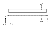
- FIG. 7 is a diagram for explaining a method for manufacturing an electroformed pipe according to Modification 2.
- the method for manufacturing an electroformed pipe according to Modification 2 will be simply referred to as the method according to Modification 2.
- the method according to Modification 2 is the same as the method according to the embodiment except for the following points.
- the virtual line L' is shown as a broken line for explanation.
- the virtual line L' passes through the center of the wire 100' substantially parallel to the X direction. That is, the virtual line L' indicates the axial direction of the wire 100'.
- an electroformed layer is formed on the outer peripheral surface of the wire 100' with the anode 40' and the wire 100' impregnated with the electroforming liquid.
- the wire 100' is rotated around the anode 40' when viewed from the X direction, thereby moving the wire 100' around the anode 40' when viewed from the X direction.
- the wire 100' moves around the anode 40' such that different parts of the outer peripheral surface of the wire 100' face the anode 40' depending on the time.
- the wire 100' may be rotated around the anode 40' while the wire 100' is fixed without being rotated around the virtual line L' when viewed from the X direction.
- the wire 100' may be rotated around the anode 40' while rotating the wire 100' around the virtual line L' when viewed from the X direction.
- the wire 100' can be rotated around the anode 40' when viewed from the X direction, for example, by a cathode motor (not shown).
- the wire rod 100' can be rotated around the virtual line L' when viewed from the X direction by the cathode motor.
- the electroforming liquid around the anode 40' can be stirred by the wire rod 100'.
- the other of the anode and the wire does not need to be fixed. That is, the other of the anode and the wire may also be moving around the one of the anode and the wire.
- the electroformed layer may not be a single layer but may be multiple layers. Further, a conductive layer may be provided on the inner peripheral surface of the electroformed layer.
- the conductive layer is, for example, plated on the outer peripheral surface of the wire.
- As the material for the conductive layer a material that is compatible with the material for the electroformed layer is used.
- the conductive layer is, for example, a metal plating layer, such as a gold plating layer.
- the conductive layer may be a metal different from gold, such as silver, iron, copper, aluminum, etc.
- a method for manufacturing an electroformed pipe and an electroforming apparatus includes the step of moving at least one of an anode and at least one wire acting as a cathode around the other of the anode and the at least one wire.
- the electroforming liquid around the other of the anode and the wire can be stirred by at least one of the anode and the wire. Therefore, compared to the case where at least one of the anode and the wire does not move around the other of the anode and the wire, the electroformed layer can be uniformly formed around the wire.
- the electroforming liquid around the wire can be stirred by the anode. Therefore, compared to the case where the anode does not move around the wire, the electroformed layer can be uniformly formed around the wire.
- the electroforming liquid around the anode can be stirred by a wire rod. Therefore, compared to the case where the wire does not move around the anode, the electroformed layer can be uniformly formed around the wire.
- the method for manufacturing an electroformed tube further includes the step of moving the outer circumferential surface of the wire around the axial direction of the wire.
- the electroformed layer can be uniformly formed around the wire, compared to the case where the outer circumferential surface of the wire does not move around the axial direction of the wire.
- the electroforming device includes a first drive unit that moves at least one of an anode, the anode, and at least one wire acting as a cathode around the other of the anode and the at least one wire. , is equipped with.
- the "first drive unit” corresponds to the “anode motor” and “cathode motor” in the above-described embodiment or modification.
- the electroformed layer is formed more uniformly around the wire than in the case where at least one of the anode and the wire does not move around the other. I can do it.
- the first drive section moves the anode around the wire.
- the electroformed layer can be uniformly formed around the wire, compared to the case where the anode does not move around the wire.
- the first drive section moves the wire around the anode.
- the electroformed layer can be uniformly formed around the wire, compared to the case where the wire does not move around the anode.
- At least one of the longitudinal direction of the anode and the longitudinal direction of the at least one wire is substantially parallel to the horizontal direction or inclined at an angle of 45° or less.
- the electroforming device further includes a second drive unit that moves the outer circumferential surface of the wire around the axial direction of the wire.
- the "second drive unit” corresponds to the "cathode motor" of the above-described embodiment or modification.
- the electroformed layer can be uniformly formed around the wire, compared to the case where the outer circumferential surface of the wire does not move around the axial direction of the wire. .
Landscapes
- Chemical & Material Sciences (AREA)
- Engineering & Computer Science (AREA)
- Chemical Kinetics & Catalysis (AREA)
- Electrochemistry (AREA)
- Materials Engineering (AREA)
- Metallurgy (AREA)
- Organic Chemistry (AREA)
- Electrical Discharge Machining, Electrochemical Machining, And Combined Machining (AREA)
- Physical Vapour Deposition (AREA)
- Electroplating Methods And Accessories (AREA)
Abstract
陽極と、陰極として動作する少なくとも1つの線材と、の少なくとも一方を、前記陽極及び前記少なくとも1つの線材の他方の周りで動かす工程を備える、電鋳管の製造方法。
Description
本発明は、電鋳管の製造方法及び電鋳装置に関する。
近年、電鋳管を製造するための様々な方法が開発されている。電鋳管は、例えば、集積回路(IC)等の検査対象物を検査するためのプローブに用いられている。例えば、特許文献1に記載の方法では、陰極として動作するステンレス製の線材と、陽極と、を電鋳液に含浸させた状態で線材を当該線材の軸方向の周りに回転させている。
線材及び陽極を動かさずに線材の外周面の同じ部分を陽極に対向させた状態で線材に電鋳層を形成することがある。しかしながら、この場合、線材の陽極に対向する部分における電鋳層の厚みが線材の他の部分における電鋳層の厚みより厚くなることがある。また、例えば特許文献1に記載されているように、線材を当該線材の軸方向の周りに回転させることがある。しかしながら、この場合であっても、電鋳層を線材の周囲に均一に形成することが難しいことがある。
本発明の目的の一例は、電鋳層を線材の周囲に均一に形成することにある。本発明の他の目的は、本明細書の記載から明らかになるであろう。
本発明の一態様は、
陽極と、陰極として動作する少なくとも1つの線材と、の少なくとも一方を、前記陽極及び前記少なくとも1つの線材の他方の周りで動かす工程を備える、電鋳管の製造方法である。
陽極と、陰極として動作する少なくとも1つの線材と、の少なくとも一方を、前記陽極及び前記少なくとも1つの線材の他方の周りで動かす工程を備える、電鋳管の製造方法である。
本発明の一態様は、
陽極と、
前記陽極と、陰極として動作する少なくとも1つの線材と、の少なくとも一方を、前記陽極及び前記少なくとも1つの線材の他方の周りで動かす第1駆動部と、
を備える電鋳装置である。
陽極と、
前記陽極と、陰極として動作する少なくとも1つの線材と、の少なくとも一方を、前記陽極及び前記少なくとも1つの線材の他方の周りで動かす第1駆動部と、
を備える電鋳装置である。
本発明の上記態様によれば、電鋳層を線材の周囲に均一に形成することができる。
以下、本発明の実施形態及び変形例について、図面を用いて説明する。すべての図面において、同様な構成要素には同様の符号を付し、適宜説明を省略する。
図1~図4は、実施形態に係る電鋳管の製造方法を説明するための図である。実施形態に係る電鋳管は、例えば、IC等の検査対象物を検査するためのプローブに利用可能である。以下、実施形態に係る電鋳管の製造方法を、単に、実施形態に係る方法という。
方向を説明するために、X方向を定義する。実施形態において、X方向は、後述する線材100の軸方向を示している。
図1~図4を参照して、実施形態に係る方法を説明する。
まず、図1に示すように、線材100を準備する。線材100は、導電性を有している。線材100は、例えば、ステンレス製である。ただし、線材100は、ステンレスと異なる材料からなっていてもよい。例えば、線材100は、鉄、銅、金、銀、真鍮、ニッケル、アルミニウム、カーボン、プラスチック、樹脂等からなっていてもよい。線材100は、X方向に略平行に延在している。線材100のX方向に垂直な断面は、略円形状となっている。線材100のX方向に垂直な直径は、例えば、10μm以上500μm以下である。X方向から見て、線材100の外周面は、金属によって覆われていてもよい。
次いで、図2に示すように、線材100のX方向の両端部を除いて、X方向から見て線材100の外周面の周囲に電鋳層200を形成する。電鋳層200は、例えば、ニッケル、金、銅、パラジウム、ロジウム、白金、銀等の金属やこれらの合金からなっている。電鋳層200は、後述する電鋳装置1を用いて形成されている。電鋳層200のX方向に垂直な厚さは、例えば、5μm以上100μm以下である。
次いで、図3に示すように、電鋳層200から線材100を除去する。例えば、電鋳層200から線材100をX方向に引き抜くことで、電鋳層200から線材100を除去することができる。ただし、電鋳層200から線材100を除去する方法はこの例に限定されない。
次いで、図4に示すように、電鋳層200を複数の片Pに切断する。切り出された各片Pは電鋳管となる。これによって、実施形態に係る電鋳管が製造される。
図5は、実施形態に係る電鋳装置1を示す図である。
方向を説明するために、X方向、Y方向及びZ方向を定義する。Z方向は、鉛直方向に平行な方向である。X方向は、Z方向に垂直な水平方向の一つである。Y方向は、Z方向及びX方向に垂直な水平方向の一つである。実施形態では、X方向が左右方向、Y方向が前後方向、Z方向が上下方向であるとして説明する。各図において、X方向及びZ方向の各々の矢印が指し示す方向をそれぞれ右方向及び上方向と定義する。各図において、Y方向を示すX付き白丸は、紙面の奥から手前に向けて前方向であることを示している。
実施形態に係る電鋳装置1は、電鋳槽10、外槽12、陰極配線32、一対の陰極モータ34、陽極40、陽極配線42、一対の陽極モータ44、一対の固定支持体46、一対の回転支持体48及び電源50を備えている。
電鋳槽10は、外槽12の内部に収容されている。電鋳槽10の上端及び外槽12の上端は、上方に向けて開口している。電鋳装置1の運転時において、電鋳槽10には、常時、電鋳液20が供給されている。これによって、電鋳槽10の上部から電鋳液20が溢れ出している。電鋳槽10から溢れ出した電鋳液20は、外槽12に流れ込んでいる。電鋳槽10から溢れ出して外槽12に流れ込んだ電鋳液20は、不図示のろ過装置によって電鋳槽10に再び供給されている。このようにして、電鋳装置1の運転時において、電鋳液20は、電鋳槽10、外槽12及びろ過装置を循環している。
電鋳液20の種類は、線材100の外周面に形成される電鋳層200の材料等の所定の条件によって決定されている。電鋳液20は、例えば、硫酸ニッケル液又はスルファミン酸ニッケル液を含み、光沢剤及びビット防止剤を必要に応じて含んでいる。
電鋳槽10内の電鋳液20には、線材100が含浸されている。実施形態において、線材100の長手方向は、X方向に略平行となっている。線材100のX方向の両端部は、陰極配線32を介して電源50に電気的に接続されている。これによって、線材100は、陰極として動作している。
図5には、説明のため、仮想線Lが破線で示されている。仮想線Lは、線材100の中心をX方向に略平行に通過している。すなわち、仮想線Lは、線材100の軸方向を示している。
X方向から見て、線材100は、一対の陰極モータ34によって、仮想線Lの周りに回転可能になっている。具体的には、一対の陰極モータ34は、線材100のX方向の両端部に接続されている。したがって、一対の陰極モータ34の駆動によって、X方向から見て、線材100は、仮想線Lの周りに回転可能になっている。
陽極40は、電鋳槽10内の電鋳液20に含浸されている。実施形態において、陽極40の長手方向は、X方向に略平行となっている。陽極40のX方向の両端部は、陽極配線42を介して電源50に電気的に接続されている。
X方向から見て、陽極40は、線材100の周囲を回転可能になっている。具体的には、陽極40のX方向の両端部の両側に一対の固定支持体46が配置されている。一対の陽極モータ44の各々は、一対の固定支持体46の各々に取り付けられている。一対の陽極モータ44は、線材100のX方向の両端部とX方向に略平行に並んでいる。すなわち、一対の陽極モータ44は、仮想線Lが一対の陽極モータ44を通過するように配置されている。一対の回転支持体48の各々の一端は、一対の陽極モータ44の各々に接続されている。一対の回転支持体48の各々の他端は、陽極40のX方向の両端部の各々に接続されている。X方向から見て、一対の回転支持体48の各々の当該他端は、一対の回転支持体48の各々の当該一端に対して、X方向に垂直な方向にずれている。一対の陽極モータ44は、X方向から見て、一対の回転支持体48の各々の当該他端を、一対の回転支持体48の各々の当該一端を中心として回転させている。これによって、X方向から見て、陽極40は、一対の回転支持体48の各々の当該他端とともに、線材100を中心とする略円軌道に沿って回転している。X方向から見て、陽極40の円運動は、等速円運動であってもよいし、又は非等速円運動であってもよい。
実施形態では、X方向から見て陽極40を線材100の周りに回転させることで、X方向から見て陽極40を線材100の周りで動かしている。したがって、X方向から見て線材100の外周面の同じ部分が、常時、陽極40に対向しないようにすることができる。これによって、線材100の外周面の特定の部分のみに電界が集中することを抑制することができる。このため、X方向から見て陽極40が線材100の周りで動かない場合と比較して、X方向から見て電鋳層200を線材100の周囲に均一に形成することができる。
実施形態では、X方向から見て陽極40を線材100の周りで動かすことで、線材100の周囲の電鋳液20を攪拌することができる。この場合、X方向から見て線材100の周りの電鋳液20において水平方向又は水平方向に近似した方向に略平行な軸の周り渦を発生させることもできる。このため、X方向から見て陽極40が線材100の周りで動かない場合と比較して、X方向から見て電鋳層200を線材100の周囲に均一に形成することができる。
実施形態では、X方向から見て線材100を仮想線Lの周りに回転させることで、X方向から見て線材100の外周面を仮想線Lの周りで動かしている。したがって、X方向から見て線材100の外周面の同じ部分が、常時、陽極40に対向しないようにすることができる。これによって、線材100の外周面の特定の部分のみに電界が集中することを抑制することができる。このため、X方向から見て線材100の外周面が仮想線Lの周りで動かない場合と比較して、X方向から見て電鋳層200を線材100の周囲に均一に形成することができる。
実施形態に係る電鋳装置1の動作は、上述の例に限定されない。
例えば、X方向から見たときの線材100の周りでの陽極40の動きは、上述の例に限定されない。例えば、X方向から見て、陽極40は、線材100の周囲を、略円軌道と異なる形状の軌道に沿って移動してもよい。例えば、X方向から見て、陽極40は、線材100の周囲を、略三角形軌道、略四角形軌道等の略多角形軌道や略楕円軌道に沿って移動してもよい。また、X方向から見て、陽極40は、線材100の周囲の所定の軌道を一方向のみに移動するのでなく、線材100の周囲の所定の軌道を往復してもよい。これらの例においても、X方向から見て線材100の外周面の同じ部分が、常時、陽極40に対向しないようにすることができる。また、線材100の周囲の電鋳液20を陽極40によって攪拌することができる。このため、X方向から見て陽極40が線材100の周りで動かない場合と比較して、X方向から見て電鋳層200を線材100の周囲に均一に形成することができる。
X方向から見たときの仮想線Lの周りでの線材100の外周面の動きは、上述の例に限定されない。例えば、X方向から見て、線材100の仮想線Lの周りの一方向の回転と、線材100の仮想線Lの周りの当該一方向の反対方向の回転と、を交互に繰り返してもよい。この例においても、X方向から見て線材100の外周面の同じ部分が、常時、陽極40に対向しないようにすることができる。このため、X方向から見て線材100の外周面が仮想線Lの周りで動かない場合と比較して、X方向から見て電鋳層200を線材100の周囲に均一に形成することができる。
電鋳槽10内の電鋳液20に含浸される線材100の本数は、1本に限定されない。例えば、複数の線材100が電鋳槽10内の電鋳液20に含浸されていてもよい。この例において、複数の線材100は、X方向に略平行に配置させることができる。X方向から見て、陽極40は、複数の線材100の周りで動かすことができる。
線材100の長手方向及び陽極40の長手方向は、水平方向に対して略平行でなくてもよい。線材100の長手方向及び陽極40の長手方向の少なくとも一方は、水平方向に対して例えば45°以下の角度で傾いていてもよい。
図6は、変形例1に係る電鋳装置1Aを示す図である。変形例1に係る電鋳装置1Aは、以下の点を除いて、実施形態に係る電鋳装置1と同様である。
変形例1に係る電鋳装置1Aは、実施形態に係る一対の陽極モータ44に代えて、単一の陽極モータ44A、回転軸45aA、一対の上部歯車45bA及び一対の下部歯車45cAを備えている。以下、変形例1において、特に断りがない限り、回転軸45aA、一対の上部歯車45bA及び一対の下部歯車45cAの各々の略中央部とは、回転軸45aA、一対の上部歯車45bA及び一対の下部歯車45cAの各々のX方向に垂直な方向における略中央部を意味する。
X方向から見て、回転軸45aAは、単一の陽極モータ44Aの駆動力によって、回転軸45aAの略中央部の周りに回転可能になっている。具体的には、図6に示す例において、回転軸45aAは、電鋳槽10の上方に位置しており、X方向に略平行に延在している。単一の陽極モータ44Aは、回転軸45aAのX方向の一端に接続されている。
一対の上部歯車45bAの各々の略中央部と、回転軸45aAのX方向の両端部の各々と、は互いに接続されている。よって、X方向から見て、一対の上部歯車45bAは、回転軸45aAの回転と同期して、回転軸45aAの略中央部の周りに回転可能になっている。
一対の下部歯車45cAは、一対の上部歯車45bAの下方に位置している。一対の上部歯車45bA及び一対の下部歯車45cAは、互いにかみ合っている。よって、一対の上部歯車45bAの回転によって、一対の下部歯車45cAは回転可能になっている。一対の下部歯車45cAの各々の略中央部と、一対の回転支持体48の各々の一端と、は互いに接続されている。一対の回転支持体48の各々の他端は、陽極40のX方向の両端部の各々に接続されている。よって、X方向から見て、一対の下部歯車45cAの回転によって、陽極40は、一対の回転支持体48の各々の当該他端とともに、線材100を中心とする略円軌道に沿って回転可能になっている。したがって、実施形態と同様にして、X方向から見て陽極40が線材100の周りで動かない場合と比較して、X方向から見て電鋳層200を線材100の周囲に均一に形成することができる。
変形例1においては、単一の陽極モータ44Aの駆動力が回転軸45aA、一対の上部歯車45bA及び一対の下部歯車45cAを介して一対の回転支持体48に伝えられている。したがって、陽極40のX方向の両側に設けられた一対の陽極モータを互いに同期させて陽極40を回転させる必要がなく、陽極40の回転の制御が容易となる。
図7は、変形例2に係る電鋳管の製造方法を説明するための図である。以下、変形例2に係る電鋳管の製造方法を、単に、変形例2に係る方法という。変形例2に係る方法は、以下の点を除いて、実施形態に係る方法と同様である。
図7には、説明のため、仮想線L´が破線で示されている。仮想線L´は、線材100´の中心をX方向に略平行に通過している。すなわち、仮想線L´は、線材100´の軸方向を示している。
図7に示す例では、実施形態と同様にして、陽極40´及び線材100´が電鋳液に含浸された状態で線材100´の外周面に電鋳層が形成されている。変形例2に係る方法では、X方向から見て線材100´を陽極40´の周りに回転させることで、X方向から見て線材100´を陽極40´の周りで動かしている。X方向から見て、線材100´は、時間に応じて線材100´の外周面の異なる部分が陽極40´に対向するように、陽極40´の周りで動いている。例えば、X方向から見て、線材100´を仮想線L´の周りで回転させずに固定させた状態で、線材100´を陽極40´の周りで回転させてもよい。或いは、X方向から見て、線材100´を仮想線L´の周りで回転させながら、線材100´を陽極40´の周りで回転させてもよい。線材100´は、例えば、不図示の陰極モータによって、X方向から見て陽極40´の周りに回転させることができる。また、線材100´は、当該陰極モータによって、X方向から見て仮想線L´の周りで回転させることができる。
変形例2に係る方法でも、X方向から見て線材100´の外周面の同じ部分が、常時、陽極40´に対向しないようにすることができる。また、陽極40´の周囲の電鋳液を線材100´によって攪拌することができる。この場合、X方向から見て陽極40´の周りの電鋳液において水平方向又は水平方向に近似した方向に略平行な軸の周り渦を発生させることもできる。このため、X方向から見て線材100´が陽極40´の周りで動かない場合と比較して、X方向から見て電鋳層を線材100´の周囲に均一に形成することができる。
以上、図面を参照して本発明の実施形態及び変形例について述べたが、これらは本発明の例示であり、上記以外の様々な構成を採用することもできる。
例えば、陽極及び線材の一方を、陽極及び線材の他方の周りで動かす場合、陽極及び線材の当該他方は、固定されていなくてもよい。すなわち、陽極及び線材の当該他方も、陽極及び線材の当該一方の周りで動いていてもよい。
電鋳層は、単層でなく、複数層であってもよい。また、電鋳層の内周面には、導電層が設けられていてもよい。導電層は、線材の外周面に、例えば、めっきされている。導電層の材料としては、電鋳層の材料と親和性がある材料が用いられる。導電層は、例えば、金めっき層等の、金属めっき層である。或いは、導電層は、例えば、銀、鉄、銅、アルミニウム等の、金と異なる金属であってもよい。
本明細書によれば、以下の態様の電鋳管の製造方法及び電鋳装置が提供される。
(態様1)
態様1では、電鋳管の製造方法が、陽極と、陰極として動作する少なくとも1つの線材と、の少なくとも一方を、前記陽極及び前記少なくとも1つの線材の他方の周りで動かす工程を備えている。
(態様1)
態様1では、電鋳管の製造方法が、陽極と、陰極として動作する少なくとも1つの線材と、の少なくとも一方を、前記陽極及び前記少なくとも1つの線材の他方の周りで動かす工程を備えている。
上述の態様によれば、線材の外周面の同じ部分が、常時、陽極に対向しないようにすることができる。また、陽極及び線材の当該他方の周囲の電鋳液を陽極及び線材の当該少なくとも一方によって攪拌することができる。このため、陽極及び線材の少なくとも一方が陽極及び線材の他方の周りで動かない場合と比較して、電鋳層を線材の周囲に均一に形成することができる。
(態様2)
態様2では、前記陽極及び前記少なくとも1つの線材の少なくとも一方を、前記陽極及び前記少なくとも1つの線材の他方の周りで動かす工程において、前記陽極を前記線材の周りで動かしている。
態様2では、前記陽極及び前記少なくとも1つの線材の少なくとも一方を、前記陽極及び前記少なくとも1つの線材の他方の周りで動かす工程において、前記陽極を前記線材の周りで動かしている。
上述の態様によれば、線材の外周面の同じ部分が、常時、陽極に対向しないようにすることができる。また、線材の周囲の電鋳液を陽極によって攪拌することができる。このため、陽極が線材の周りで動かない場合と比較して、電鋳層を線材の周囲に均一に形成することができる。
(態様3)
態様3では、前記陽極及び前記少なくとも1つの線材の少なくとも一方を、前記陽極及び前記少なくとも1つの線材の他方の周りで動かす工程において、前記線材を前記陽極の周りで動かしている。
態様3では、前記陽極及び前記少なくとも1つの線材の少なくとも一方を、前記陽極及び前記少なくとも1つの線材の他方の周りで動かす工程において、前記線材を前記陽極の周りで動かしている。
上述の態様によれば、線材の外周面の同じ部分が、常時、陽極に対向しないようにすることができる。また、陽極の周囲の電鋳液を線材によって攪拌することができる。このため、線材が陽極の周りで動かない場合と比較して、電鋳層を線材の周囲に均一に形成することができる。
(態様4)
態様4では、前記陽極及び前記少なくとも1つの線材の少なくとも一方を、前記陽極及び前記少なくとも1つの線材の他方の周りで動かす工程において、前記陽極の長手方向及び前記少なくとも1つの線材の長手方向の少なくとも一方が、水平方向に対して略平行又は45°以下の角度で傾いている。
態様4では、前記陽極及び前記少なくとも1つの線材の少なくとも一方を、前記陽極及び前記少なくとも1つの線材の他方の周りで動かす工程において、前記陽極の長手方向及び前記少なくとも1つの線材の長手方向の少なくとも一方が、水平方向に対して略平行又は45°以下の角度で傾いている。
上述の態様によれば、陽極及び少なくとも1つの線材の周りの電鋳液において、水平方向又は水平方向に近似した方向に略平行な軸の周りの渦を発生させることもできる。
(態様5)
態様5では、電鋳管の製造方法が、前記線材の外周面を前記線材の軸方向の周りで動かす工程をさらに備えている。
態様5では、電鋳管の製造方法が、前記線材の外周面を前記線材の軸方向の周りで動かす工程をさらに備えている。
上述の態様によれば、線材の外周面の同じ部分が、常時、陽極に対向しないようにすることができる。このため、線材の外周面が当該線材の軸方向の周りで動かない場合と比較して、電鋳層を線材の周囲に均一に形成することができる。
(態様6)
態様6では、電鋳装置が、陽極と、前記陽極と、陰極として動作する少なくとも1つの線材と、の少なくとも一方を、前記陽極及び前記少なくとも1つの線材の他方の周りで動かす第1駆動部と、を備えている。
態様6では、電鋳装置が、陽極と、前記陽極と、陰極として動作する少なくとも1つの線材と、の少なくとも一方を、前記陽極及び前記少なくとも1つの線材の他方の周りで動かす第1駆動部と、を備えている。
「第1駆動部」は、上述の実施形態又は変形例の「陽極モータ」、「陰極モータ」に相当する。
上述の態様によれば、態様1と同様にして、陽極及び線材の少なくとも一方が陽極及び線材の他方の周りで動かない場合と比較して、電鋳層を線材の周囲に均一に形成することができる。
(態様7)
態様7では、前記第1駆動部が前記陽極を前記線材の周りで動かしている。
態様7では、前記第1駆動部が前記陽極を前記線材の周りで動かしている。
上述の態様によれば、態様2と同様にして、陽極が線材の周りで動かない場合と比較して、電鋳層を線材の周囲に均一に形成することができる。
(態様8)
態様8では、前記第1駆動部が前記線材を前記陽極の周りで動かしている。
態様8では、前記第1駆動部が前記線材を前記陽極の周りで動かしている。
上述の態様によれば、態様3と同様にして、線材が陽極の周りで動かない場合と比較して、電鋳層を線材の周囲に均一に形成することができる。
(態様9)
態様9では、前記陽極の長手方向及び前記少なくとも1つの線材の長手方向の少なくとも一方が、水平方向に対して略平行又は45°以下の角度で傾いている。
態様9では、前記陽極の長手方向及び前記少なくとも1つの線材の長手方向の少なくとも一方が、水平方向に対して略平行又は45°以下の角度で傾いている。
上述の態様によれば、陽極及び少なくとも1つの線材の周りの電鋳液において、水平方向又は水平方向に近似した方向に略平行な軸の周りの渦を発生させることもできる。
(態様10)
態様10では、電鋳装置が、前記線材の外周面を前記線材の軸方向の周りで動かす第2駆動部をさらに備えている。
態様10では、電鋳装置が、前記線材の外周面を前記線材の軸方向の周りで動かす第2駆動部をさらに備えている。
「第2駆動部」は、上述の実施形態又は変形例の「陰極モータ」に相当する。
上述の態様によれば、態様5と同様にして、線材の外周面が当該線材の軸方向の周りで動かない場合と比較して、電鋳層を線材の周囲に均一に形成することができる。
この出願は、2022年4月27日に出願された日本出願特願2022-073041号を基礎とする優先権を主張し、その開示の全てをここに取り込む。
1,1A 電鋳装置、10 電鋳槽、12 外槽、20 電鋳液、32 陰極配線、34 陰極モータ、40,40´ 陽極、42 陽極配線、44,44A 陽極モータ、45aA 回転軸、45bA 上部歯車、45cA 下部歯車、46 固定支持体、48 回転支持体、50 電源、100,100´ 線材、200 電鋳層、L,L´ 仮想線、P 片
Claims (10)
- 陽極と、陰極として動作する少なくとも1つの線材と、の少なくとも一方を、前記陽極及び前記少なくとも1つの線材の他方の周りで動かす工程を備える、電鋳管の製造方法。
- 前記陽極及び前記少なくとも1つの線材の少なくとも一方を、前記陽極及び前記少なくとも1つの線材の他方の周りで動かす工程において、前記陽極を前記線材の周りで動かす、請求項1に記載の電鋳管の製造方法。
- 前記陽極及び前記少なくとも1つの線材の少なくとも一方を、前記陽極及び前記少なくとも1つの線材の他方の周りで動かす工程において、前記線材を前記陽極の周りで動かす、請求項1に記載の電鋳管の製造方法。
- 前記陽極及び前記少なくとも1つの線材の少なくとも一方を、前記陽極及び前記少なくとも1つの線材の他方の周りで動かす工程において、前記陽極の長手方向及び前記少なくとも1つの線材の長手方向の少なくとも一方が、水平方向に対して略平行又は45°以下の角度で傾いている、請求項1に記載の電鋳管の製造方法。
- 前記線材の外周面を前記線材の軸方向の周りで動かす工程をさらに備える、請求項1~4のいずれか一項に記載の電鋳管の製造方法。
- 陽極と、
前記陽極と、陰極として動作する少なくとも1つの線材と、の少なくとも一方を、前記陽極及び前記少なくとも1つの線材の他方の周りで動かす第1駆動部と、
を備える電鋳装置。 - 前記第1駆動部が前記陽極を前記線材の周りで動かす、請求項6に記載の電鋳装置。
- 前記第1駆動部が前記線材を前記陽極の周りで動かす、請求項6に記載の電鋳装置。
- 前記陽極の長手方向及び前記少なくとも1つの線材の長手方向の少なくとも一方が、水平方向に対して略平行又は45°以下の角度で傾いている、請求項6に記載の電鋳装置。
- 前記線材の外周面を前記線材の軸方向の周りで動かす第2駆動部をさらに備える、請求項6~9のいずれか一項に記載の電鋳装置。
Priority Applications (1)
| Application Number | Priority Date | Filing Date | Title |
|---|---|---|---|
| JP2024517234A JPWO2023210459A1 (ja) | 2022-04-27 | 2023-04-19 |
Applications Claiming Priority (2)
| Application Number | Priority Date | Filing Date | Title |
|---|---|---|---|
| JP2022-073041 | 2022-04-27 | ||
| JP2022073041 | 2022-04-27 |
Publications (1)
| Publication Number | Publication Date |
|---|---|
| WO2023210459A1 true WO2023210459A1 (ja) | 2023-11-02 |
Family
ID=88518629
Family Applications (1)
| Application Number | Title | Priority Date | Filing Date |
|---|---|---|---|
| PCT/JP2023/015562 Ceased WO2023210459A1 (ja) | 2022-04-27 | 2023-04-19 | 電鋳管の製造方法及び電鋳装置 |
Country Status (3)
| Country | Link |
|---|---|
| JP (1) | JPWO2023210459A1 (ja) |
| TW (1) | TW202413731A (ja) |
| WO (1) | WO2023210459A1 (ja) |
Citations (9)
| Publication number | Priority date | Publication date | Assignee | Title |
|---|---|---|---|---|
| JP2001192880A (ja) * | 2000-01-14 | 2001-07-17 | Shinichi Okamoto | 光ファイバコネクタ用部品の製造方法 |
| JP2001214292A (ja) * | 2000-01-28 | 2001-08-07 | Tetsuo Tanaka | 電鋳に使用する芯線ホルダー |
| JP2002241983A (ja) * | 2001-02-16 | 2002-08-28 | Hikari Tekku Kk | スリ−ブの製造方法 |
| JP2002241982A (ja) * | 2001-02-15 | 2002-08-28 | Atsushi Ishidoya | 電鋳による光ファイバコネクタ用フェルールの製造方法 |
| KR20040039943A (ko) * | 2002-11-05 | 2004-05-12 | 주식회사 유니테크 | 자전 및 공전을 이용한 전주 도금 장치 |
| JP2005060780A (ja) * | 2003-08-13 | 2005-03-10 | Odate Seisakusho:Kk | 芯線ホルダーおよび細管製造用電鋳装置 |
| JP2005232531A (ja) * | 2004-02-19 | 2005-09-02 | Hitoshi Mikajiri | 電鋳による多心金属管の製造方法 |
| WO2006135057A1 (ja) * | 2005-06-17 | 2006-12-21 | Luzcom Inc. | Ni電鋳製超微細管及びNi電鋳製超微細リング並びにこれらの用途 |
| JP2017155299A (ja) * | 2016-03-03 | 2017-09-07 | 株式会社エンプラス | 電鋳装置 |
-
2023
- 2023-04-19 WO PCT/JP2023/015562 patent/WO2023210459A1/ja not_active Ceased
- 2023-04-19 JP JP2024517234A patent/JPWO2023210459A1/ja active Pending
- 2023-04-19 TW TW112114595A patent/TW202413731A/zh unknown
Patent Citations (9)
| Publication number | Priority date | Publication date | Assignee | Title |
|---|---|---|---|---|
| JP2001192880A (ja) * | 2000-01-14 | 2001-07-17 | Shinichi Okamoto | 光ファイバコネクタ用部品の製造方法 |
| JP2001214292A (ja) * | 2000-01-28 | 2001-08-07 | Tetsuo Tanaka | 電鋳に使用する芯線ホルダー |
| JP2002241982A (ja) * | 2001-02-15 | 2002-08-28 | Atsushi Ishidoya | 電鋳による光ファイバコネクタ用フェルールの製造方法 |
| JP2002241983A (ja) * | 2001-02-16 | 2002-08-28 | Hikari Tekku Kk | スリ−ブの製造方法 |
| KR20040039943A (ko) * | 2002-11-05 | 2004-05-12 | 주식회사 유니테크 | 자전 및 공전을 이용한 전주 도금 장치 |
| JP2005060780A (ja) * | 2003-08-13 | 2005-03-10 | Odate Seisakusho:Kk | 芯線ホルダーおよび細管製造用電鋳装置 |
| JP2005232531A (ja) * | 2004-02-19 | 2005-09-02 | Hitoshi Mikajiri | 電鋳による多心金属管の製造方法 |
| WO2006135057A1 (ja) * | 2005-06-17 | 2006-12-21 | Luzcom Inc. | Ni電鋳製超微細管及びNi電鋳製超微細リング並びにこれらの用途 |
| JP2017155299A (ja) * | 2016-03-03 | 2017-09-07 | 株式会社エンプラス | 電鋳装置 |
Also Published As
| Publication number | Publication date |
|---|---|
| JPWO2023210459A1 (ja) | 2023-11-02 |
| TW202413731A (zh) | 2024-04-01 |
Similar Documents
| Publication | Publication Date | Title |
|---|---|---|
| EP1164208A2 (en) | Electroplating method using combination of vibrational flow in plating bath and plating current of pulse | |
| KR102350158B1 (ko) | 동은 합금을 이용한 도전성 부재, 접촉핀 및 장치 | |
| WO2023210459A1 (ja) | 電鋳管の製造方法及び電鋳装置 | |
| JP3889689B2 (ja) | 電鋳管の製造方法及び電鋳管 | |
| JP2008025833A (ja) | Ni電鋳製コイル状超微細スプリング及びコイル状スプリング構造を一部に備えているNi電鋳パイプ | |
| US20170336350A1 (en) | Static Disk Electrode for Electroplating Bath Analysis | |
| US20240344222A1 (en) | Method of manufacturing an electroformed pipe | |
| JPH11193485A (ja) | 細孔チューブの製造方法 | |
| JP4496522B2 (ja) | 電鋳による多心金属管の製造方法 | |
| WO2023210458A1 (ja) | 軸材及び電鋳管の製造方法 | |
| JP2006063434A (ja) | 電鋳法による高精度な金属微細管の製造方法。 | |
| JP2008013822A (ja) | 揺動式めっき装置 | |
| TWI298647B (ja) | ||
| JP4342066B2 (ja) | 芯線ホルダー | |
| JPWO2006135057A1 (ja) | Ni電鋳製超微細管及びNi電鋳製超微細リング並びにこれらの用途 | |
| EP1728897B1 (en) | Electrocast tube producing method and electrocast tube | |
| JP2006291345A (ja) | 電鋳法による高精度な金属微細管の製造方法 | |
| JP2017125224A (ja) | 金属管及びその製造方法 | |
| JP2008223138A (ja) | めっき方法およびめっき用治具 | |
| CN1888142A (zh) | 由电铸得到的多心金属管的制造方法 | |
| CN214736190U (zh) | 一种电镀液均匀搅拌的电镀装置 | |
| CN220012864U (zh) | 一种适用于片式元器件的实验室简易电镀工装 | |
| JP2013039616A (ja) | 管の接合方法 | |
| JP2001207285A (ja) | 電鋳に使用する芯線ホルダー | |
| JP2002322585A (ja) | 金型めっき装置 |
Legal Events
| Date | Code | Title | Description |
|---|---|---|---|
| 121 | Ep: the epo has been informed by wipo that ep was designated in this application |
Ref document number: 23796201 Country of ref document: EP Kind code of ref document: A1 |
|
| WWE | Wipo information: entry into national phase |
Ref document number: 2024517234 Country of ref document: JP |
|
| NENP | Non-entry into the national phase |
Ref country code: DE |
|
| 122 | Ep: pct application non-entry in european phase |
Ref document number: 23796201 Country of ref document: EP Kind code of ref document: A1 |