WO2023210444A1 - 冷凍サイクル装置 - Google Patents
冷凍サイクル装置 Download PDFInfo
- Publication number
- WO2023210444A1 WO2023210444A1 PCT/JP2023/015489 JP2023015489W WO2023210444A1 WO 2023210444 A1 WO2023210444 A1 WO 2023210444A1 JP 2023015489 W JP2023015489 W JP 2023015489W WO 2023210444 A1 WO2023210444 A1 WO 2023210444A1
- Authority
- WO
- WIPO (PCT)
- Prior art keywords
- semiconductor switching
- voltage
- working medium
- circuit
- refrigeration cycle
- Prior art date
- Legal status (The legal status is an assumption and is not a legal conclusion. Google has not performed a legal analysis and makes no representation as to the accuracy of the status listed.)
- Ceased
Links
Images




Classifications
-
- F—MECHANICAL ENGINEERING; LIGHTING; HEATING; WEAPONS; BLASTING
- F04—POSITIVE - DISPLACEMENT MACHINES FOR LIQUIDS; PUMPS FOR LIQUIDS OR ELASTIC FLUIDS
- F04B—POSITIVE-DISPLACEMENT MACHINES FOR LIQUIDS; PUMPS
- F04B49/00—Control, e.g. of pump delivery, or pump pressure of, or safety measures for, machines, pumps, or pumping installations, not otherwise provided for, or of interest apart from, groups F04B1/00 - F04B47/00
- F04B49/06—Control using electricity
-
- F—MECHANICAL ENGINEERING; LIGHTING; HEATING; WEAPONS; BLASTING
- F04—POSITIVE - DISPLACEMENT MACHINES FOR LIQUIDS; PUMPS FOR LIQUIDS OR ELASTIC FLUIDS
- F04B—POSITIVE-DISPLACEMENT MACHINES FOR LIQUIDS; PUMPS
- F04B35/00—Piston pumps specially adapted for elastic fluids and characterised by the driving means to their working members, or by combination with, or adaptation to, specific driving engines or motors, not otherwise provided for
- F04B35/04—Piston pumps specially adapted for elastic fluids and characterised by the driving means to their working members, or by combination with, or adaptation to, specific driving engines or motors, not otherwise provided for the means being electric
-
- F—MECHANICAL ENGINEERING; LIGHTING; HEATING; WEAPONS; BLASTING
- F25—REFRIGERATION OR COOLING; COMBINED HEATING AND REFRIGERATION SYSTEMS; HEAT PUMP SYSTEMS; MANUFACTURE OR STORAGE OF ICE; LIQUEFACTION SOLIDIFICATION OF GASES
- F25B—REFRIGERATION MACHINES, PLANTS OR SYSTEMS; COMBINED HEATING AND REFRIGERATION SYSTEMS; HEAT PUMP SYSTEMS
- F25B13/00—Compression machines, plants or systems, with reversible cycle
-
- F—MECHANICAL ENGINEERING; LIGHTING; HEATING; WEAPONS; BLASTING
- F25—REFRIGERATION OR COOLING; COMBINED HEATING AND REFRIGERATION SYSTEMS; HEAT PUMP SYSTEMS; MANUFACTURE OR STORAGE OF ICE; LIQUEFACTION SOLIDIFICATION OF GASES
- F25B—REFRIGERATION MACHINES, PLANTS OR SYSTEMS; COMBINED HEATING AND REFRIGERATION SYSTEMS; HEAT PUMP SYSTEMS
- F25B31/00—Compressor arrangements
- F25B31/02—Compressor arrangements of motor-compressor units
-
- F—MECHANICAL ENGINEERING; LIGHTING; HEATING; WEAPONS; BLASTING
- F25—REFRIGERATION OR COOLING; COMBINED HEATING AND REFRIGERATION SYSTEMS; HEAT PUMP SYSTEMS; MANUFACTURE OR STORAGE OF ICE; LIQUEFACTION SOLIDIFICATION OF GASES
- F25B—REFRIGERATION MACHINES, PLANTS OR SYSTEMS; COMBINED HEATING AND REFRIGERATION SYSTEMS; HEAT PUMP SYSTEMS
- F25B49/00—Arrangement or mounting of control or safety devices
- F25B49/02—Arrangement or mounting of control or safety devices for compression type machines, plants or systems
-
- F—MECHANICAL ENGINEERING; LIGHTING; HEATING; WEAPONS; BLASTING
- F25—REFRIGERATION OR COOLING; COMBINED HEATING AND REFRIGERATION SYSTEMS; HEAT PUMP SYSTEMS; MANUFACTURE OR STORAGE OF ICE; LIQUEFACTION SOLIDIFICATION OF GASES
- F25B—REFRIGERATION MACHINES, PLANTS OR SYSTEMS; COMBINED HEATING AND REFRIGERATION SYSTEMS; HEAT PUMP SYSTEMS
- F25B49/00—Arrangement or mounting of control or safety devices
- F25B49/02—Arrangement or mounting of control or safety devices for compression type machines, plants or systems
- F25B49/022—Compressor control arrangements
-
- F—MECHANICAL ENGINEERING; LIGHTING; HEATING; WEAPONS; BLASTING
- F04—POSITIVE - DISPLACEMENT MACHINES FOR LIQUIDS; PUMPS FOR LIQUIDS OR ELASTIC FLUIDS
- F04B—POSITIVE-DISPLACEMENT MACHINES FOR LIQUIDS; PUMPS
- F04B2203/00—Motor parameters
- F04B2203/02—Motor parameters of rotating electric motors
- F04B2203/0202—Voltage
-
- F—MECHANICAL ENGINEERING; LIGHTING; HEATING; WEAPONS; BLASTING
- F25—REFRIGERATION OR COOLING; COMBINED HEATING AND REFRIGERATION SYSTEMS; HEAT PUMP SYSTEMS; MANUFACTURE OR STORAGE OF ICE; LIQUEFACTION SOLIDIFICATION OF GASES
- F25B—REFRIGERATION MACHINES, PLANTS OR SYSTEMS; COMBINED HEATING AND REFRIGERATION SYSTEMS; HEAT PUMP SYSTEMS
- F25B2400/00—Component parts or details not otherwise provided for in this subclass
- F25B2400/12—Inflammable refrigerants
-
- F—MECHANICAL ENGINEERING; LIGHTING; HEATING; WEAPONS; BLASTING
- F25—REFRIGERATION OR COOLING; COMBINED HEATING AND REFRIGERATION SYSTEMS; HEAT PUMP SYSTEMS; MANUFACTURE OR STORAGE OF ICE; LIQUEFACTION SOLIDIFICATION OF GASES
- F25B—REFRIGERATION MACHINES, PLANTS OR SYSTEMS; COMBINED HEATING AND REFRIGERATION SYSTEMS; HEAT PUMP SYSTEMS
- F25B2600/00—Control issues
- F25B2600/02—Compressor control
- F25B2600/021—Inverters therefor
Definitions
- the present disclosure relates to a refrigeration cycle device.
- R410A has been widely used as a working medium (heat medium, refrigerant) for refrigeration cycle devices.
- R410A has a large global warming potential (GWP) of 2090. Therefore, from the perspective of preventing global warming, research and development are being carried out on working media with lower GWP.
- Patent Document 1 discloses 1,1,2-trifluoroethylene (HFO1123) as a working medium having a smaller GWP than R410A.
- Patent Document 2 discloses 1,2-difluoroethylene (HFO1132) as a working medium having a smaller GWP than R410A.
- HFO1123 and HFO1132 have a lower GWP than R410A, but are thereby less stable than R410A. For example, due to the generation of radicals, a disproportionation reaction of HFO1123 or HFO1132 may proceed, and HFO1123 and HFO1132 may change into another compound.
- the present disclosure provides a refrigeration cycle device that makes it possible to suppress a disproportionation reaction of a working medium.
- a refrigeration cycle device includes a refrigeration cycle circuit that includes a compressor, a condenser, an expansion valve, and an evaporator, and in which a working medium circulates, and a control device that controls the compressor of the refrigeration cycle circuit.
- the working medium contains ethylene-based fluoroolefin as a refrigerant component.
- the compressor includes an airtight container that forms a flow path for the working medium, a compression mechanism that is located within the airtight container and compresses the working medium, and a compression mechanism that is located within the airtight container and operates the compression mechanism.
- An electric motor is provided.
- the control device includes a drive circuit that drives the electric motor, and a control circuit that controls the drive circuit.
- the drive circuit includes a first output point that outputs a first voltage, a second output point that outputs a second voltage lower than the first voltage, and a third output point between the first voltage and the second voltage.
- a converter circuit having a plurality of output points including one or more third output points that output voltage; a first semiconductor switching element group connected between the first output point and the electric motor; a second semiconductor switching element group connected between the output point and the electric motor; and one or more third semiconductor switching element groups connected between the one or more third output points and the electric motor, respectively.
- an inverter circuit including a plurality of semiconductor switching element groups.
- the control circuit executes PWM control of the plurality of semiconductor switching element groups of the inverter circuit of the drive circuit so that the drive circuit operates the motor.
- a refrigeration cycle device includes a refrigeration cycle circuit that includes a compressor, a condenser, an expansion valve, and an evaporator, and in which a working medium circulates, and a control device that controls the compressor of the refrigeration cycle circuit.
- the working medium contains ethylene-based fluoroolefin as a refrigerant component.
- the compressor includes an airtight container that forms a flow path for the working medium, a compression mechanism that is located within the airtight container and compresses the working medium, and a compression mechanism that is located within the airtight container and operates the compression mechanism.
- An electric motor is provided.
- the control device includes a multilevel inverter that drives the electric motor, and a control circuit that performs PWM control on the multilevel inverter.
- aspects of the present disclosure enable suppression of disproportionation reactions in the working medium.
- Block diagram of a configuration example of a refrigeration cycle device Schematic diagram of a configuration example of the compressor and control device of the refrigeration cycle device in FIG. 1 Waveform diagram of an example of control operation of the drive circuit by the control circuit of the control device in FIG. 2 Waveform diagram of an example of control operation of the drive circuit by the control circuit of the control device in FIG. 2 Waveform diagram of an example of control operation of the drive circuit by the control circuit of the control device in FIG. 2 Schematic illustration of surge voltage in the refrigeration cycle device in Figure 1 Schematic illustration of surge voltage in a comparative refrigeration cycle device
- a prefix such as “first” or “second” will be added to the name of the component, but the reference numeral attached to the component will be used. If they are distinguishable from each other, the prefixes such as “first” and “second” may be omitted in consideration of the readability of the text.
- FIG. 1 is a block diagram of a configuration example of a refrigeration cycle device 1 according to the present embodiment.
- the refrigeration cycle device 1 in FIG. 1 constitutes, for example, an air conditioner capable of cooling operation and heating operation.
- the refrigeration cycle device 1 in FIG. 1 includes a refrigeration cycle circuit 2 and a control device 3.
- the refrigeration cycle circuit 2 constitutes a flow path through which a working medium circulates.
- the working medium contains ethylene-based fluoroolefin as a refrigerant component.
- the ethylene-based fluoroolefin is preferably an ethylene-based fluoroolefin that undergoes a disproportionation reaction.
- Examples of ethylene-based fluoroolefins that cause disproportionation reactions include 1,1,2-trifluoroethylene (HFO1123), trans-1,2-difluoroethylene (HFO1132(E)), and cis-1,2-difluoroethylene.
- the working medium may contain multiple types of refrigerant components.
- the working medium may contain an ethylene-based fluoroolefin as a main refrigerant component and a compound other than the ethylene-based fluoroolefin as an auxiliary refrigerant component.
- sub-refrigerant components include hydrofluorocarbons (HFC), hydrofluoroolefins (HFO), saturated hydrocarbons, carbon dioxide, and the like.
- hydrofluorocarbons examples include difluoromethane, difluoroethane, trifluoroethane, tetrafluoroethane, pentafluoroethane, pentafluoropropane, hexafluoropropane, heptafluoropropane, pentafluorobutane, heptafluorocyclopentane, etc. It will be done.
- hydrofluoroolefins examples include monofluoropropene, trifluoropropene, tetrafluoropropene, pentafluoropropene, hexafluorobutene, and the like.
- saturated hydrocarbons examples include ethane, n-propane, cyclopropane, n-butane, cyclobutane, isobutane (2-methylpropane), methylcyclopropane, n-pentane, isopentane (2-methylbutane), neopentane (2, 2-dimethylpropane), methylcyclobutane, and the like.
- the working medium may further contain a disproportionation inhibitor that suppresses the disproportionation reaction of the ethylene-based fluoroolefin.
- disproportionation inhibitors include saturated hydrocarbons or haloalkanes.
- saturated hydrocarbons include ethane, n-propane, cyclopropane, n-butane, cyclobutane, isobutane (2-methylpropane), methylcyclopropane, n-pentane, isopentane (2-methylbutane), neopentane (2, 2-dimethylpropane), methylcyclobutane, and the like.
- n-propane is preferred.
- haloalkanes examples include haloalkanes having 1 or 2 carbon atoms.
- haloalkanes i.e., halomethanes
- having one carbon number examples include (mono)iodomethane (CH 3 I), diiodomethane (CH 2 I 2 ), dibromomethane (CH 2 Br 2 ), bromomethane (CH 3 Br), and dichloromethane.
- haloalkanes having two carbon atoms
- haloalkanes having two carbon atoms
- CF 3 CH 2 I 1,1,1-trifluoro-2-iodoethane
- CH 3 CH 2 I monoiodoethane
- CH 3 CH 2 Br monobromoethane
- 1,1,1-triiodoethane CH 3 CI 3
- the working medium may contain one or more haloalkanes having 1 or 2 carbon atoms. That is, only one type of haloalkane having 1 or 2 carbon atoms may be used, or two or more types may be used in an appropriate combination.
- the refrigeration cycle circuit 2 in FIG. 1 includes a compressor 4, a first heat exchanger 5, an expansion valve 6, a second heat exchanger 7, and a four-way valve 8.
- the refrigeration cycle device 1 in FIG. 1 includes an outdoor unit 1a and an indoor unit 1b.
- the outdoor unit 1a includes a control device 3, a compressor 4, a first heat exchanger 5, an expansion valve 6, and a four-way valve 8.
- the outdoor unit 1a further includes a first blower 5a for promoting heat exchange in the first heat exchanger 5.
- the indoor unit 1b includes a second heat exchanger 7.
- the indoor unit 1b further includes a second blower 7a for promoting heat exchange in the second heat exchanger 7.
- the compressor 4 compresses the working medium and increases the pressure of the working medium.
- the compressor 4 will be explained in detail later.
- the first heat exchanger 5 and the second heat exchanger 7 exchange heat between the working medium circulating in the refrigeration cycle circuit 2 and external air (for example, outside air or indoor air).
- the expansion valve 6 adjusts the pressure of the working medium (evaporation pressure) and the flow rate of the working medium.
- the four-way valve 8 switches the direction of the working medium circulating through the refrigeration cycle circuit 2 between a first direction corresponding to cooling operation and a second direction corresponding to heating operation.
- the first direction as shown by the solid arrow A1 in FIG. This is the direction in which the heat exchanger 7 is circulated in order.
- the compressor 4 compresses and discharges the gaseous working medium, whereby the gaseous working medium is sent to the first heat exchanger 5 via the four-way valve 8.
- the first heat exchanger 5 exchanges heat between the outside air and the gaseous working medium, and the gaseous working medium is condensed and liquefied.
- the liquid working medium is depressurized by the expansion valve 6 and sent to the second heat exchanger 7.
- heat is exchanged between the liquid working medium and the indoor air, and the gaseous working medium evaporates to become a gaseous working medium.
- the gaseous working medium returns to the compressor 4 via a four-way valve 8 .
- the first heat exchanger 5 functions as a condenser
- the second heat exchanger 7 functions as an evaporator. Therefore, during cooling, the indoor unit 1b blows air cooled by heat exchange in the second heat exchanger 7 into the room.
- the second direction as shown by the dashed arrow A2 in FIG. This is the direction in which the heat exchanger 5 is circulated in order.
- the compressor 4 compresses and discharges the gaseous working medium, whereby the gaseous working medium is sent to the second heat exchanger 7 via the four-way valve 8.
- the second heat exchanger 7 exchanges heat between the indoor air and the gaseous working medium, and the gaseous working medium is condensed and liquefied.
- the liquid working medium is depressurized by the expansion valve 6 and sent to the first heat exchanger 5 .
- heat is exchanged between the liquid working medium and the outside air, and the gaseous working medium evaporates to become a gaseous working medium.
- the gaseous working medium returns to the compressor 4 via a four-way valve 8 .
- the first heat exchanger 5 functions as an evaporator
- the second heat exchanger 7 functions as a condenser. Therefore, during heating, the indoor unit 1b blows air warmed by heat exchange in the second heat exchanger 7 into the room.
- FIG. 1 is a schematic diagram of a configuration example of the compressor 4 and the control device 3.
- the compressor 4 is, for example, a hermetic compressor.
- the compressor 4 may be of rotary type, scroll type, or other known type.
- the compressor 4 in FIG. 2 includes a closed container 40, a compression mechanism 41, and an electric motor 42.
- the closed container 40 constitutes a flow path for the working medium 20.
- the closed container 40 has an intake pipe 401 and a discharge pipe 402.
- the working medium 20 is sucked into the closed container 40 through the suction pipe 401, compressed by the compression mechanism 41, and then discharged out of the closed container 40 through the discharge pipe 402.
- the inside of the closed container 40 is filled with high temperature and high pressure working medium 20 and lubricating oil.
- the bottom of the closed container 40 constitutes an oil storage section that stores a mixed liquid of the working medium 20 and lubricating oil.
- the compression mechanism 41 is located within the closed container 40 and compresses the working medium.
- the compression mechanism 41 may have a conventionally known configuration.
- the compression mechanism 41 includes, for example, a cylinder forming a compression chamber, a rolling piston disposed in the compression chamber within the cylinder, and a crankshaft coupled to the rolling piston.
- the electric motor 42 is located inside the closed container 40 and operates the compression mechanism 41.
- the electric motor 42 is, for example, a brushless motor (three-phase brushless motor).
- the electric motor 42 includes, for example, a rotor fixed to the crankshaft of the compression mechanism 41 and a stator provided around the rotor.
- the stator is, for example, configured by winding stator windings (magnet wire, etc.) around a stator core (magnetic steel plate, etc.) through insulating paper, either in concentrated or distributed manner.
- the stator winding is covered with an insulating member.
- the insulating member include polyethylene terephthalate (PET), polyethylene naphthalate (PEN), aramid polymer, polyphenylene sulfide (PPS), and the like.
- the compressor 4 may include an accumulator to prevent liquid compression in the compression chamber of the compression mechanism 41.
- the accumulator separates the working medium into a gaseous working medium and a liquid working medium, and guides only the gaseous working medium from the suction pipe 401 into the closed container 40 .
- the control device 3 in FIG. 2 includes a drive circuit 31 and a control circuit 32.
- the drive circuit 31 drives the electric motor 42.
- the drive circuit 31 in FIG. 2 supplies drive power to the electric motor 42 based on the power from the power source 10.
- power supply 10 is an AC power supply.
- Drive circuit 31 supplies drive power to electric motor 42 based on AC power from power supply 10 .
- the drive circuit 31 supplies three-phase AC power to the electric motor 42 as drive power.
- Drive circuit 31 includes a converter circuit 311 and an inverter circuit 312.
- the converter circuit 311 converts AC power from the power supply 10 into DC power.
- Converter circuit 311 includes a rectifier circuit 311a and a smoothing circuit 311b.
- the rectifier circuit 311a is a diode bridge composed of a plurality of diodes D1 to D4.
- the power supply 10 is connected between the input terminals of the rectifier circuit 311a (the connection point between diodes D1 and D2, and the connection point between diodes D3 and D4), and the output terminal of the rectification circuit 311a (the connection point between diodes D1 and D3, and A smoothing circuit 311b is connected between the connection point of diodes D2 and D4.
- power supply 10 is an AC power supply.
- the smoothing circuit 311b smoothes and outputs the voltage between the output terminals of the rectifier circuit 311a.
- the smoothing circuit 311b includes a series circuit of an inductor L1 and smoothing capacitors C1 and C2.
- the connection point between the inductor L1 and the smoothing capacitor C1 is the first output point P1 that outputs the first voltage.
- the connection point between the diodes D2 and D4 and the smoothing capacitor C2 is a second output point P2 that outputs a second voltage lower than the first voltage.
- the connection point between the smoothing capacitor C1 and the smoothing capacitor C2 is a third output point P3 that outputs a third voltage between the first voltage and the second voltage.
- the first output point P1 is a high voltage point
- the second output point P2 is a low voltage point
- the third output point P3 is an intermediate voltage point. It is a point.
- the smoothing capacitor C1 and the smoothing capacitor C2 have the same capacitance. Therefore, the voltage between the first voltage and the third voltage is equal to the voltage between the second voltage and the third voltage.
- the inverter circuit 312 supplies AC power to the motor 42 based on the DC power from the converter circuit 311.
- inverter circuit 312 of FIG. 2 supplies three-phase AC power to motor 42.
- the inverter circuit 312 includes a plurality of semiconductor switching elements U1 to U4, V1 to V4, and W1 to W4.
- the semiconductor switching elements U1 to U4, V1 to V4, and W1 to W4 are, for example, transistors.
- the semiconductor switching elements U1 to U4 constitute a series circuit.
- a series circuit of semiconductor switching elements U1 to U4 is connected between a first output point P1 and a second output point P2 of the converter circuit 311.
- a connection point between semiconductor switching elements U1 and U2 is connected to a third output point P3 of converter circuit 311 via diode D5.
- the anode of the diode D5 is connected to the third output point P3, and the cathode of the diode D5 is connected to the connection point between the semiconductor switching elements U1 and U2.
- the connection point between the semiconductor switching elements U2 and U3 constitutes a U-phase output terminal Pu connected to the U-phase input terminal of the electric motor 42.
- a connection point between semiconductor switching elements U3 and U4 is connected to a third output point P3 of converter circuit 311 via diode D6.
- the cathode of the diode D6 is connected to the third output point P3, and the anode of the diode D6 is connected to the connection point between the semiconductor switching elements U3 and U4.
- the semiconductor switching elements V1 to V4 constitute a series circuit.
- a series circuit of semiconductor switching elements V1 to V4 is connected between a first output point P1 and a second output point P2 of the converter circuit 311.
- a connection point between semiconductor switching elements V1 and V2 is connected to a third output point P3 of converter circuit 311 via diode D7.
- the anode of the diode D7 is connected to the third output point P3, and the cathode of the diode D7 is connected to the connection point between the semiconductor switching elements V1 and V2.
- the connection point between the semiconductor switching elements V2 and V3 constitutes a V-phase output terminal Pv connected to the V-phase input terminal of the motor 42.
- a connection point between semiconductor switching elements V3 and V4 is connected to a third output point P3 of converter circuit 311 via diode D8.
- the cathode of the diode D8 is connected to the third output point P3, and the anode of the diode D8 is connected to the connection point between the semiconductor switching elements V3 and V4.
- the semiconductor switching elements W1 to W4 constitute a series circuit.
- a series circuit of semiconductor switching elements W1 to W4 is connected between a first output point P1 and a second output point P2 of the converter circuit 311.
- a connection point between semiconductor switching elements W1 and W2 is connected to a third output point P3 of converter circuit 311 via diode D9.
- the anode of the diode D9 is connected to the third output point P3, and the cathode of the diode D9 is connected to the connection point between the semiconductor switching elements W1 and W2.
- a connection point between the semiconductor switching elements W2 and W3 constitutes a W-phase output terminal Pw connected to a W-phase input terminal of the electric motor 42.
- a connection point between semiconductor switching elements W3 and W4 is connected to a third output point P3 of converter circuit 311 via diode D10.
- the cathode of the diode D10 is connected to the third output point P3, and the anode of the diode D10 is connected to the connection point of the semiconductor switching elements W3 and W4.
- a series circuit of semiconductor switching elements U1 to U4 constitutes a U-phase leg.
- a series circuit of semiconductor switching elements V1 to V4 constitutes a V-phase leg.
- a series circuit of semiconductor switching elements W1 to W4 constitutes a W-phase leg.
- the semiconductor switching elements U1 to U4, V1 to V4, and W1 to W4 are also called arms.
- the semiconductor switching elements U1, U2, V1, V2, W1, and W2 constitute a first semiconductor switching element group connected between the first output point P1 and the electric motor 42.
- the semiconductor switching elements U1 and U2 constitute a U-phase first semiconductor switching element group connected between the first output point P1 and the U-phase input terminal of the electric motor 42.
- the semiconductor switching elements V1 and V2 constitute a V-phase first semiconductor switching element group connected between the first output point P1 and the V-phase input terminal of the motor 42.
- the semiconductor switching elements W1 and W2 constitute a W-phase first semiconductor switching element group connected between the first output point P1 and the W-phase input terminal of the motor 42.
- the semiconductor switching elements U3, U4, V3, V4, W3, and W4 constitute a second semiconductor switching element group connected between the second output point P2 and the electric motor 42.
- the semiconductor switching elements U3 and U4 constitute a U-phase second semiconductor switching element group connected between the second output point P2 and the U-phase input terminal of the electric motor 42.
- the semiconductor switching elements V3 and V4 constitute a V-phase second semiconductor switching element group connected between the second output point P2 and the V-phase input terminal of the motor 42.
- the semiconductor switching elements W3 and W4 constitute a W-phase second semiconductor switching element group connected between the second output point P2 and the W-phase input terminal of the motor 42.
- the semiconductor switching elements U2, U3, V2, V3, W2, and W3 constitute a third semiconductor switching element group connected between the third output point P3 and the electric motor 42.
- the semiconductor switching elements U2 and U3 constitute a U-phase third semiconductor switching element group connected between the third output point P3 and the U-phase input terminal of the electric motor 42.
- the semiconductor switching elements V2 and V3 constitute a V-phase third semiconductor switching element group connected between the third output point P3 and the V-phase input terminal of the motor 42.
- the semiconductor switching elements W2 and W3 constitute a W-phase third semiconductor switching element group connected between the third output point P3 and the W-phase input terminal of the electric motor 42.
- the converter circuit 311 has a first output point P1 that outputs a first voltage, a second output point P2 that outputs a second voltage lower than the first voltage, and a second output point P2 that outputs a second voltage lower than the first voltage. It has a plurality of output points including a third output point P3 that outputs a third voltage between the voltage and the third output point P3.
- the inverter circuit 312 includes a first semiconductor switching element group (semiconductor switching elements U1, U2, V1, V2, W1, W2) connected between the first output point P1 and the electric motor 42, and a second output point P2.
- a second semiconductor switching element group (semiconductor switching elements U3, U4, V3, V4, W3, W4) connected between the electric motor 42 and a third semiconductor switching element group (semiconductor switching elements U3, U4, V3, V4, W3, W4) connected between the third output point P3 and the electric motor 42 It has a plurality of semiconductor switching element groups including a semiconductor switching element group (semiconductor switching elements U2, U3, V2, V3, W2, W3).
- the drive circuit 31 in FIG. 2 is a so-called multi-level inverter, particularly a three-level inverter.
- the control circuit 32 can be realized, for example, by a computer system including at least one or more processors (microprocessors) and one or more memories.
- the control circuit 32 controls the drive circuit 31.
- the control circuit 32 executes PWM control of a plurality of semiconductor switching element groups of the inverter circuit 312 of the drive circuit 31 so that the drive circuit 31 operates the electric motor 42 .
- the control circuit 32 controls the plurality of semiconductors in the inverter circuit 312 of the drive circuit 31 so that the inverter circuit 312 supplies three-phase AC power to the motor 42 based on the DC power from the smoothing circuit 311b. Controls switching of switching elements U1 to U4, V1 to V4, and W1 to W4.
- 3 to 5 are waveform diagrams of examples of control operations of the drive circuit 31 by the control circuit 32 of the control device 3.
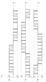
- FIG. 3 shows the waveforms of the U-phase output voltage command value Vref_u, the V-phase output voltage command value Vref_v, the W-phase output voltage command value Vref_w, and the first and second carrier triangular waves Vth1 and Vth2.
- the U-phase output voltage command value Vref_u, the V-phase output voltage command value Vref_v, and the W-phase output voltage command value Vref_w correspond to three-phase AC U, V, and W-phase sinusoidal AC voltages.
- the value of the first carrier triangular wave Vth1 is 0 or more, and the value of the second carrier triangular wave Vth2 is 0 or less.
- the control circuit 32 controls the semiconductor switching elements U1 to Vth2 based on the U-phase output voltage command value Vref_u, the V-phase output voltage command value Vref_v, the W-phase output voltage command value Vref_w, and the first and second carrier triangular waves Vth1 and Vth2. Controls switching of U4, V1 to V4, and W1 to W4.
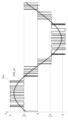
- FIG. 4 shows the waveforms of the U-phase output voltage Vu, the V-phase output voltage Vv, and the W-phase output voltage Vw.
- the U-phase output voltage Vu is the voltage at the U-phase output terminal Pu.
- the V-phase output voltage Vv is the voltage at the V-phase output terminal Pv.
- the W-phase output voltage Vw is the voltage at the W-phase output terminal Pw.
- the U-phase output voltage Vu, the V-phase output voltage Vv, and the W-phase output voltage Vw are expressed, assuming that the potential difference between the first voltage and the second voltage is E, and the third voltage is 0.
- the control circuit 32 turns on the U-phase first semiconductor switching element group (semiconductor switching elements U1, U2) when the U-phase output voltage command value Vref_u is larger than the first carrier triangular wave Vth1 (first state).
- the control circuit 32 turns on the U-phase third semiconductor switching element group (semiconductor switching elements U2, U3) when the U-phase output voltage command value Vref_u is less than or equal to the first carrier triangular wave Vth1 and greater than or equal to the second carrier triangular wave Vth2. (third state).
- the control circuit 32 turns on the U-phase second semiconductor switching element group (semiconductor switching elements U3, U4) when the U-phase output voltage command value Vref_u is smaller than the second carrier triangular wave Vth2 (second state). Thereby, the control circuit 32 outputs the U-phase output voltage Vu of FIG. 4 from the U-phase output terminal Pu of the drive circuit 31 to the U-phase input terminal of the electric motor 42.
- Table 1 below shows a summary of on/off conditions for the semiconductor switching elements U1 to U4. In Table 1 below, for semiconductor switching elements U1 to U4, "1" indicates on and "0" indicates off.
- the control circuit 32 turns on the V-phase first semiconductor switching element group (semiconductor switching elements V1, V2) when the V-phase output voltage command value Vref_v is larger than the first carrier triangular wave Vth1 (first state).
- the control circuit 32 turns on the V-phase third semiconductor switching element group (semiconductor switching elements V2, V3) when the V-phase output voltage command value Vref_v is less than or equal to the first carrier triangular wave Vth1 and greater than or equal to the second carrier triangular wave Vth2. (third state).
- the control circuit 32 turns on the V-phase second semiconductor switching element group (semiconductor switching elements V3, V4) when the V-phase output voltage command value Vref_v is smaller than the second carrier triangular wave Vth2 (second state). Thereby, the control circuit 32 outputs the V-phase output voltage Vv of FIG. 4 from the V-phase output terminal Pv of the drive circuit 31 to the V-phase input terminal of the motor 42.
- Table 2 below shows a summary of on/off conditions for the semiconductor switching elements V1 to V4. In Table 2 below, for semiconductor switching elements V1 to V4, "1" indicates on and "0" indicates off.
- the control circuit 32 turns on the W-phase first semiconductor switching element group (semiconductor switching elements W1, W2) when the W-phase output voltage command value Vref_w is larger than the first carrier triangular wave Vth1 (first state).
- the control circuit 32 turns on the W-phase third semiconductor switching element group (semiconductor switching elements W2, W3) when the W-phase output voltage command value Vref_w is less than or equal to the first carrier triangular wave Vth1 and greater than or equal to the second carrier triangular wave Vth2. (third state).
- the control circuit 32 turns on the W-phase second semiconductor switching element group (semiconductor switching elements W3, W4) when the W-phase output voltage command value Vref_w is smaller than the second carrier triangular wave Vth2 (second state). Thereby, the control circuit 32 outputs the W-phase output voltage Vw of FIG. 4 from the W-phase output terminal Pw of the drive circuit 31 to the W-phase input terminal of the motor 42.
- Table 3 below shows a summary of on/off conditions for the semiconductor switching elements W1 to W4. In Table 3 below, for semiconductor switching elements W1 to W4, "1" indicates on and "0" indicates off.
- FIG. 5 shows the waveform of the voltage Vuv between the U-phase input terminal and the V-phase input terminal of the electric motor 42.
- Voltage Vuv corresponds to the voltage between the U-phase output terminal Vu and V-phase output terminal Vv of the inverter circuit 312 of the drive circuit 31.
- the drive circuit 31 can provide five levels of voltage: E, E/2, 0, -E/2, and -E.
- Vref_uv indicates the difference between the U-phase output voltage command value Vref_u and the V-phase output voltage command value Vref_v. It is understood from FIG. 5 that the waveform of the voltage Vuv between the U-phase input terminal and the V-phase input terminal of the electric motor 42 can be made closer to a sine wave.
- the control circuit 32 executes PWM control of the plurality of semiconductor switching element groups of the inverter circuit 312 of the drive circuit 31 so that the drive circuit 31 operates the electric motor 42.
- the motor 42 is driven by the drive circuit 31
- voltage changes occur due to switching of the semiconductor switching elements U1 to U4, V1 to V4, and W1 to W4 of the inverter circuit 312 of the drive circuit 31.
- inductance and stray capacitance exist in the wiring between the drive circuit 31 and the motor 42. Therefore, voltage changes caused by switching of the semiconductor switching elements U1 to U4, V1 to V4, and W1 to W4 may generate a surge voltage due to LC resonance.
- a surge voltage may be generated due to switching of the semiconductor switching elements U1 to U4, V1 to V4, and W1 to W4 of the inverter circuit 312 of the drive circuit 31.
- the surge voltage varies depending on conditions such as the switching frequency of the semiconductor switching elements U1 to U4, V1 to V4, W1 to W4, and the wiring between the drive circuit 31 and the electric motor 42, but , W1 to W4 may reach about twice the voltage change caused by switching.
- a surge voltage may cause a discharge phenomenon such as corona discharge between windings.
- Corona discharge has a weak energy of about several picocoulombs per cycle, but if the switching frequency is high, there is a possibility that corona discharge will gradually transition to arc discharge. Therefore, when a surge voltage is applied to the motor 42, the insulation coating of the windings of the motor 42 deteriorates and is damaged, and it is thought that this may eventually lead to dielectric breakdown of the motor 42.
- the compressor 4 since heat is generated in the electric motor 42 when the electric motor 42 is driven, heat dissipation from the electric motor 42 is required. It is very efficient to use a working medium to dissipate heat from the electric motor 42.
- the electric motor 42 is arranged within the closed container 40 so as to be able to contact the working medium.
- the discharge phenomenon can directly affect the working medium.
- discharge phenomena are likely to generate heat and radicals that can contribute to disproportionation reactions in the working medium. This means that there is a high possibility that the disproportionation reaction of the working medium will proceed.
- the insulation performance of the insulation coating of the windings of the motor 42 In order to prevent deterioration or damage to the insulation coating of the windings of the motor 42 due to surge voltage, it is possible to strengthen the insulation performance of the insulation coating of the windings of the motor 42. For example, it is possible to strengthen the insulation performance by increasing the thickness of the insulation coating of the windings of the electric motor 42. However, as the insulation coating of the windings of the motor 42 becomes thicker, the filling factor of the windings decreases, which contributes to deterioration of the performance of the motor 42. When the performance of the electric motor 42 decreases, the operating efficiency of the refrigeration cycle device 1 decreases.
- the converter circuit 311 outputs the first voltage at the first output point P1 and the second voltage lower than the first voltage. It has a plurality of output points including a second output point P2 and a third output point P3 that outputs a third voltage between the first voltage and the second voltage.
- the inverter circuit 312 includes a first semiconductor switching element group (semiconductor switching elements U1, U2, V1, V2, W1, W2) connected between the first output point P1 and the electric motor 42, and a second output point P2.
- a second semiconductor switching element group (semiconductor switching elements U3, U4, V3, V4, W3, W4) connected between the electric motor 42 and a second semiconductor switching element group (semiconductor switching elements U3, U4, V3, V4, W3, W4) connected between the third output point P3 and the electric motor 42, respectively. It has a plurality of semiconductor switching element groups including three semiconductor switching element groups (semiconductor switching elements U2, U3, V2, V3, W2, W3).
- the converter circuit 311 has the third output point P3 that outputs the third voltage between the first voltage and the second voltage.
- the voltage change caused by switching is not the voltage between the first voltage and the second voltage, but the voltage between the first voltage and the third voltage, or the voltage between the second voltage and the third voltage. can be reduced to As described above, the refrigeration cycle device 1 according to the present embodiment can reduce the voltage change itself during switching of the semiconductor switching elements U1 to U4, V1 to V4, and W1 to W4, so that the surge voltage itself can be suppressed. enable.
- FIG. 6 is a schematic explanatory diagram of surge voltage in the refrigeration cycle device 1 according to the present embodiment. More specifically, FIG. 6 shows the waveform of the voltage Vuv between the U-phase input terminal and the V-phase input terminal of the electric motor 42. The waveform of the voltage Vuv in FIG. 6 is simplified from the waveform of the voltage Vuv in FIG. 5, giving priority to the ease of viewing the drawing. Also in FIG. 6, Vref_uv indicates the difference between the U-phase output voltage command value Vref_u and the V-phase output voltage command value Vref_v.
- the third voltage is an intermediate voltage between the first voltage and the second voltage.
- the voltage between the first voltage and the second voltage is E
- the voltage between the first voltage and the third voltage is E/2
- the voltage between the second voltage and the third voltage is E/2.
- the voltage is E/2. Therefore, the increase in voltage due to the surge voltage Vs during switching is E/2 both between the first voltage and the third voltage and between the second voltage and the third voltage. Therefore, as shown in FIG. 6, the absolute value of the maximum voltage applied to the motor 42 is 3E/2.
- FIG. 7 is a schematic explanatory diagram of surge voltage in a refrigeration cycle device of a comparative example.
- the comparative example corresponds to a case where the converter circuit 311 of the drive circuit 31 does not have a third output point P3 that outputs a third voltage between the first voltage and the second voltage.
- the drive circuit 31 cannot provide voltages at five levels of E, E/2, 0, -E/2, and -E; All you can do is apply voltage. Therefore, the increase in voltage due to the surge voltage Vs during switching is E. Therefore, as shown in FIG. 7, the absolute value of the maximum voltage applied to the motor 42 is 2E, which is larger than in the case of FIG.
- the refrigeration cycle device 1 can reduce the voltage change itself during switching of the semiconductor switching elements U1 to U4, V1 to V4, and W1 to W4, so the surge voltage itself can be reduced. enables suppression of Since the surge voltage itself is reduced, the possibility of deterioration or damage to the insulation coating of the windings of the motor 42 due to the surge voltage is reduced. By reducing the possibility of deterioration or damage to the insulation coating of the windings of the electric motor 42, the occurrence of a discharge phenomenon is suppressed. By suppressing the occurrence of the discharge phenomenon, the disproportionation reaction of the working medium is suppressed. Therefore, the refrigeration cycle device 1 according to the present embodiment makes it possible to suppress the disproportionation reaction of the working medium.
- the refrigeration cycle device 1 described above includes a compressor 4, a condenser (first heat exchanger 5, second heat exchanger 7), an expansion valve 6, and an evaporator (first heat exchanger 5, second heat exchanger 7). 7), a refrigeration cycle circuit 2 in which a working medium 20 circulates, and a control device 3 that controls a compressor 4 of the refrigeration cycle circuit 2.
- the working medium 20 contains ethylene-based fluoroolefin as a refrigerant component.
- the compressor 4 includes an airtight container 40 that forms a flow path for the working medium 20, a compression mechanism 41 that is located inside the airtight container 40 and compresses the working medium 20, and a compression mechanism 41 that is located inside the airtight container 40 and compresses the compression mechanism 41.
- the control device 3 includes a drive circuit 31 that drives an electric motor 42 and a control circuit 32 that controls the drive circuit 31.
- the drive circuit 31 has a first output point P1 that outputs a first voltage, a second output point P2 that outputs a second voltage lower than the first voltage, and a third voltage between the first voltage and the second voltage.
- a converter circuit 311 having a plurality of output points P1, P2, and P3 including a third output point P3 that outputs a first semiconductor switching element group (semiconductor switching elements U1, U2, V1, V2, W1, W2) and a second semiconductor switching element group (semiconductor switching elements U3, U4, V3, V4, W3) connected between the second output point P2 and the motor 42.
- the control circuit 32 executes PWM control of a plurality of semiconductor switching element groups of the inverter circuit 312 of the drive circuit 31 so that the drive circuit 31 operates the electric motor 42 . This configuration makes it possible to suppress disproportionation reactions of the working medium.
- the control circuit 32 turns on the first semiconductor switching element group (semiconductor switching elements U1, U2, V1, V2, W1, W2) to connect the first output point P1 to the electric motor 42. state and a second state in which the second semiconductor switching element group (semiconductor switching elements U3, U4, V3, V4, W3, W4) is turned on and the second output point P2 is connected to the electric motor 42, A third state is passed in which the third semiconductor switching element group (semiconductor switching elements U2, U3, V2, V3, W2, W3) is turned on and the third output point P3 is connected to the motor 42.
- This configuration can enhance the effect of suppressing the disproportionation reaction of the working medium.
- the ethylene-based fluoroolefins include ethylene-based fluoroolefins in which a disproportionation reaction occurs. This configuration makes it possible to suppress disproportionation reactions of the working medium.
- the ethylene-based fluoroolefins include 1,1,2-trifluoroethylene, trans-1,2-difluoroethylene, cis-1,2-difluoroethylene, 1,1-difluoroethylene, and tetrafluoroethylene. , or monofluoroethylene. This configuration makes it possible to suppress disproportionation reactions of the working medium.
- the working medium 20 further includes difluoromethane as a refrigerant component. This configuration makes it possible to suppress disproportionation reactions of the working medium.
- the working medium 20 further contains saturated hydrocarbons. This configuration makes it possible to suppress disproportionation reactions of the working medium.
- the working medium 20 contains a haloalkane having 1 or 2 carbon atoms as a disproportionation inhibitor that suppresses the disproportionation reaction of ethylene-based fluoroolefins. This configuration makes it possible to suppress disproportionation reactions of the working medium.
- the saturated hydrocarbons include n-propane. This configuration makes it possible to suppress disproportionation reactions of the working medium.
- the refrigeration cycle device 1 described above includes a compressor 4, a condenser (first heat exchanger 5, second heat exchanger 7), an expansion valve 6, and an evaporator (first heat exchanger 5, second heat exchanger 7). 7), a refrigeration cycle circuit 2 in which a working medium 20 circulates, and a control device 3 that controls a compressor 4 of the refrigeration cycle circuit 2.
- the working medium 20 contains ethylene-based fluoroolefin as a refrigerant component.
- the compressor 4 includes an airtight container 40 that forms a flow path for the working medium 20, a compression mechanism 41 that is located inside the airtight container 40 and compresses the working medium 20, and a compression mechanism 41 that is located inside the airtight container 40 and compresses the compression mechanism 41. and an electric motor 42 to be operated.
- the control device 3 includes a multilevel inverter (drive circuit 31) that drives an electric motor 42, and a control circuit 32 that performs PWM control on the multilevel inverter. This configuration makes it possible to suppress disproportionation reactions of
- Embodiments of the present disclosure are not limited to the above embodiments.
- the embodiments described above can be modified in various ways depending on the design, etc., as long as the objects of the present disclosure can be achieved. Modifications of the above embodiment are listed below.
- the modified examples described below can be applied in combination as appropriate.
- the power source 10 may be a variety of alternating current power sources, in particular a commercial power source.
- a commercial power source may be a variety of alternating current power sources, in particular a commercial power source.
- the drive circuit 31 can be configured to be able to drive the motor 42 with various commercial power sources.
- the drive circuit 31 may be configured to supply drive power corresponding to the type of electric motor 42, etc.
- the driving power is not limited to three-phase AC power, but may be single-phase AC power.
- the converter circuit 311 may have a plurality of third output points.
- the plurality of third output points may output mutually different third voltages.
- the inverter circuit 312 may include a plurality of third semiconductor switching element groups connected between the plurality of third output points and the motor 42, respectively. If the total number of the first output point P1, the second output point P2, and the plurality of third output points P3 is n, the drive circuit 31 can provide a voltage of (2 ⁇ n ⁇ 1) level. By increasing n, the voltage waveform applied to the motor 42 by the drive circuit 31 can be made closer to a sine wave.
- the circuit configuration of the inverter circuit 312 is not limited to the circuit configuration of FIG. 2.
- the circuit configuration of the inverter circuit 312 in FIG. 2 is a so-called NPC (Neutral-Point-Clamped) system, but it may be an A-NPC (Advanced-NPC) system.
- the inverter circuit 312 may include a plurality of semiconductor switching element groups each connected between a plurality of output points having different voltages and a motor.
- the plurality of semiconductor switching elements constituting the plurality of semiconductor switching element groups may include a semiconductor switching element commonly included in two or more semiconductor switching element groups.
- the refrigeration cycle device is not limited to an air conditioner (so-called room air conditioner (RAC)) configured in which one indoor unit is connected to one outdoor unit.
- the refrigeration cycle device may be an air conditioner (so-called package air conditioner (PAC), building multi-air conditioner (VRF)) in which a plurality of indoor units are connected to one or more outdoor units.
- the refrigeration cycle device is not limited to an air conditioner, but may be a freezing or refrigeration device such as a refrigerator or a freezer.
- the first aspect is a refrigeration cycle device (1), which includes a compressor (4), a condenser (first heat exchanger 5, second heat exchanger 7), an expansion valve (6), and an evaporator (second heat exchanger 7).
- a refrigeration cycle circuit (2) in which a working medium (20) circulates, and control for controlling the compressor (4) of the refrigeration cycle circuit (2).
- a device (3) is provided.
- the working medium (20) contains ethylene-based fluoroolefin as a refrigerant component.
- the compressor (4) includes a closed container (40) that constitutes a flow path for the working medium (20), and a compression mechanism (located in the closed container (40) that compresses the working medium (20).
- the control device (3) includes a drive circuit (31) that drives the electric motor (42), and a control circuit (32) that controls the drive circuit (31).
- the drive circuit (31) has a first output point (P1) that outputs a first voltage, a second output point (P2) that outputs a second voltage lower than the first voltage, and a second output point (P2) that outputs a second voltage lower than the first voltage.
- a converter circuit (311) having a plurality of output points including one or more third output points (P3) that output a third voltage between the first output point (P1) and the electric motor; (42) (semiconductor switching elements U1, U2, V1, V2, W1, W2) connected between the second output point (P2) and the electric motor (42).
- a second semiconductor switching element group semiconductor switching elements U3, U4, V3, V4, W3, W4 connected between the second semiconductor switching element group (semiconductor switching elements U3, U4, V3, V4, W3, W4) connected between the one or more third output points (P3) and the motor, respectively; an inverter circuit (312) having a plurality of semiconductor switching element groups including one or more third semiconductor switching element groups (semiconductor switching elements U2, U3, V2, V3, W2, W3).
- the control circuit (32) performs PWM control of the plurality of semiconductor switching element groups of the inverter circuit (312) of the drive circuit (31) so that the drive circuit (31) operates the electric motor (42). Execute.
- This embodiment makes it possible to suppress disproportionation reactions of the working medium.
- the second aspect is a refrigeration cycle device (1) based on the first aspect.
- the control circuit (32) turns on the first semiconductor switching element group (semiconductor switching elements U1, U2, V1, V2, W1, W2) to cause the electric motor (42) to A first state in which the output point (P1) is connected, and a second state in which the second semiconductor switching element group (semiconductor switching elements U3, U4, V3, V4, W3, W4) is turned on to output the second output to the motor (42).
- the one or more third semiconductor switching element group semiconductor switching elements U2, U3, V2, V3, W2, W3 is turned on and the electric motor ( 42) through a third state in which the one or more third output points (P3) are connected.
- This aspect can enhance the effect of suppressing the disproportionation reaction of the working medium while increasing the operating efficiency of the refrigeration cycle device (1).
- the third aspect is a refrigeration cycle device (1) based on the first or second aspect.
- the ethylene-based fluoroolefin includes an ethylene-based fluoroolefin in which a disproportionation reaction occurs. This embodiment makes it possible to suppress disproportionation reactions of the working medium.
- a fourth aspect is a refrigeration cycle device (1) based on any one of the first to third aspects.
- the ethylene-based fluoroolefin is 1,1,2-trifluoroethylene, trans-1,2-difluoroethylene, cis-1,2-difluoroethylene, 1,1-difluoroethylene, tetrafluoroethylene, Ethylene or monofluoroethylene. This embodiment makes it possible to suppress disproportionation reactions of the working medium.
- a fifth aspect is a refrigeration cycle device (1) based on any one of the first to fourth aspects.
- the working medium (20) further includes difluoromethane as the refrigerant component. This embodiment makes it possible to suppress disproportionation reactions of the working medium.
- a sixth aspect is a refrigeration cycle device (1) based on any one of the first to fifth aspects.
- the working medium (20) further comprises a saturated hydrocarbon. This embodiment makes it possible to suppress disproportionation reactions of the working medium.
- a seventh aspect is a refrigeration cycle device (1) based on any one of the first to sixth aspects.
- the working medium contains a haloalkane having 1 or 2 carbon atoms as a disproportionation inhibitor that suppresses the disproportionation reaction of the ethylene-based fluoroolefin. This embodiment makes it possible to suppress disproportionation reactions of the working medium.
- the eighth aspect is a refrigeration cycle device (1) based on the sixth aspect.
- the saturated hydrocarbon comprises n-propane. This embodiment makes it possible to suppress disproportionation reactions of the working medium.
- a ninth aspect is a refrigeration cycle device (1), which includes a compressor (4), a condenser (first heat exchanger 5, second heat exchanger 7), an expansion valve (6), and an evaporator (first 1 heat exchanger 5, a second heat exchanger 7), a refrigeration cycle circuit (2) in which a working medium (20) circulates, and control for controlling the compressor (4) of the refrigeration cycle circuit (2).
- a device (3) is provided.
- the working medium (20) contains ethylene-based fluoroolefin as a refrigerant component.
- the compressor (4) includes a closed container (40) that constitutes a flow path for the working medium (20), and a compression mechanism (located in the closed container (40) that compresses the working medium (20).
- the control device (3) includes a multilevel inverter (drive circuit 31) that drives the electric motor (42), and a control circuit (32) that performs PWM control on the multilevel inverter. This embodiment makes it possible to suppress disproportionation reactions of the working medium.
- the second to eighth aspects can be applied to the ninth aspect with appropriate changes.
- the second to eighth aspects are optional elements and are not essential.
- the present disclosure is applicable to refrigeration cycle devices. Specifically, the present disclosure is applicable to a refrigeration cycle device in which the working medium contains an ethylene-based fluoroolefin as a refrigerant component.
- Refrigeration cycle device Refrigeration cycle circuit 20
- Working medium Control device 31
- Drive circuit 311
- Converter circuit P1 First output point P2 Second output point P3
- Third output point 312
- Inverter circuit U1, U2, U3, U4
- Semiconductor switching element V1, V2, V3, V4 semiconductor switching element W1, W2, W3, W4 semiconductor switching element 32
- control circuit 4 compressor 40 sealed container 41 compression mechanism 42 electric motor 5
- first heat exchanger (condenser, evaporator) 6
- Expansion valve Second heat exchanger (condenser, evaporator)
Landscapes
- Engineering & Computer Science (AREA)
- Mechanical Engineering (AREA)
- General Engineering & Computer Science (AREA)
- Physics & Mathematics (AREA)
- Thermal Sciences (AREA)
- Inverter Devices (AREA)
- Control Of Positive-Displacement Pumps (AREA)
Priority Applications (4)
| Application Number | Priority Date | Filing Date | Title |
|---|---|---|---|
| US18/860,395 US20250290502A1 (en) | 2022-04-28 | 2023-04-18 | Refrigeration cycle device |
| CN202380036409.6A CN119096050A (zh) | 2022-04-28 | 2023-04-18 | 制冷循环装置 |
| EP23796187.5A EP4517088A4 (en) | 2022-04-28 | 2023-04-18 | REFRIGERATING CYCLE DEVICE |
| JP2024517223A JPWO2023210444A1 (https=) | 2022-04-28 | 2023-04-18 |
Applications Claiming Priority (2)
| Application Number | Priority Date | Filing Date | Title |
|---|---|---|---|
| JP2022075303 | 2022-04-28 | ||
| JP2022-075303 | 2022-04-28 |
Publications (1)
| Publication Number | Publication Date |
|---|---|
| WO2023210444A1 true WO2023210444A1 (ja) | 2023-11-02 |
Family
ID=88518617
Family Applications (1)
| Application Number | Title | Priority Date | Filing Date |
|---|---|---|---|
| PCT/JP2023/015489 Ceased WO2023210444A1 (ja) | 2022-04-28 | 2023-04-18 | 冷凍サイクル装置 |
Country Status (5)
| Country | Link |
|---|---|
| US (1) | US20250290502A1 (https=) |
| EP (1) | EP4517088A4 (https=) |
| JP (1) | JPWO2023210444A1 (https=) |
| CN (1) | CN119096050A (https=) |
| WO (1) | WO2023210444A1 (https=) |
Citations (6)
| Publication number | Priority date | Publication date | Assignee | Title |
|---|---|---|---|---|
| WO2012157765A1 (ja) | 2011-05-19 | 2012-11-22 | 旭硝子株式会社 | 作動媒体および熱サイクルシステム |
| WO2012157764A1 (ja) | 2011-05-19 | 2012-11-22 | 旭硝子株式会社 | 作動媒体および熱サイクルシステム |
| JP2017003197A (ja) * | 2015-06-11 | 2017-01-05 | パナソニックIpマネジメント株式会社 | 冷凍サイクル装置 |
| JP2020070930A (ja) * | 2018-10-29 | 2020-05-07 | パナソニックIpマネジメント株式会社 | 冷凍サイクル装置 |
| JP2021161316A (ja) * | 2020-04-01 | 2021-10-11 | パナソニックIpマネジメント株式会社 | 冷凍サイクル用作動媒体および冷凍サイクルシステム |
| JP2022044019A (ja) * | 2020-09-04 | 2022-03-16 | ダイキン工業株式会社 | 冷媒としての使用、および、冷凍サイクル装置 |
Family Cites Families (2)
| Publication number | Priority date | Publication date | Assignee | Title |
|---|---|---|---|---|
| US9829226B2 (en) * | 2011-04-28 | 2017-11-28 | Mitsubishi Electric Corporation | Heat pump device, heat pump system, and method for controlling inverter |
| JP6857813B2 (ja) * | 2018-03-05 | 2021-04-14 | パナソニックIpマネジメント株式会社 | 冷凍サイクル装置 |
-
2023
- 2023-04-18 WO PCT/JP2023/015489 patent/WO2023210444A1/ja not_active Ceased
- 2023-04-18 CN CN202380036409.6A patent/CN119096050A/zh active Pending
- 2023-04-18 JP JP2024517223A patent/JPWO2023210444A1/ja active Pending
- 2023-04-18 EP EP23796187.5A patent/EP4517088A4/en active Pending
- 2023-04-18 US US18/860,395 patent/US20250290502A1/en active Pending
Patent Citations (6)
| Publication number | Priority date | Publication date | Assignee | Title |
|---|---|---|---|---|
| WO2012157765A1 (ja) | 2011-05-19 | 2012-11-22 | 旭硝子株式会社 | 作動媒体および熱サイクルシステム |
| WO2012157764A1 (ja) | 2011-05-19 | 2012-11-22 | 旭硝子株式会社 | 作動媒体および熱サイクルシステム |
| JP2017003197A (ja) * | 2015-06-11 | 2017-01-05 | パナソニックIpマネジメント株式会社 | 冷凍サイクル装置 |
| JP2020070930A (ja) * | 2018-10-29 | 2020-05-07 | パナソニックIpマネジメント株式会社 | 冷凍サイクル装置 |
| JP2021161316A (ja) * | 2020-04-01 | 2021-10-11 | パナソニックIpマネジメント株式会社 | 冷凍サイクル用作動媒体および冷凍サイクルシステム |
| JP2022044019A (ja) * | 2020-09-04 | 2022-03-16 | ダイキン工業株式会社 | 冷媒としての使用、および、冷凍サイクル装置 |
Also Published As
| Publication number | Publication date |
|---|---|
| EP4517088A1 (en) | 2025-03-05 |
| CN119096050A (zh) | 2024-12-06 |
| JPWO2023210444A1 (https=) | 2023-11-02 |
| EP4517088A4 (en) | 2025-07-30 |
| US20250290502A1 (en) | 2025-09-18 |
Similar Documents
| Publication | Publication Date | Title |
|---|---|---|
| CN100395954C (zh) | 电动机控制装置、压缩机、空调机、和冷藏库 | |
| CN103348578B (zh) | 逆流防止单元、电力变换装置以及制冷空气调节装置 | |
| CN103125066A (zh) | 电力变换装置以及冷冻空调装置 | |
| CN116897498A (zh) | 电力转换装置、马达驱动装置以及空调机 | |
| WO2023210444A1 (ja) | 冷凍サイクル装置 | |
| WO2017109848A1 (ja) | 電力変換装置、及び、この電力変換装置を備えた空気調和装置 | |
| US20250321035A1 (en) | Refrigeration cycle device | |
| WO2024203926A1 (ja) | 駆動回路、放流装置、制御装置、冷凍サイクル装置、制御方法、プログラム | |
| JP7260814B2 (ja) | モータ駆動装置および冷却装置 | |
| US20260025087A1 (en) | Inverter circuit, drive circuit, control device, refrigeration cycle device, control method, and program | |
| WO2025028193A1 (ja) | 制御装置、冷凍サイクル装置 | |
| JP6132911B2 (ja) | 逆流防止装置、電力変換装置、モータ駆動装置及び冷凍空気調和装置 | |
| WO2023210446A1 (ja) | 冷凍サイクル装置 | |
| WO2024203857A1 (ja) | 制御装置、放流装置、冷凍サイクル装置、制御方法、プログラム | |
| CN118265877A (zh) | 电力转换装置、马达驱动装置以及制冷循环应用设备 | |
| US20260110476A1 (en) | Control device, refrigeration cycle device, control method, program | |
| WO2024203908A1 (ja) | コンバータ回路、駆動回路、制御装置、冷凍サイクル装置、制御方法、プログラム | |
| CN119968772A (zh) | 同步机控制装置、压缩系统、制冷循环装置 | |
| JP7054756B2 (ja) | 電力変換装置および空気調和機 | |
| JP2008118759A (ja) | モータ駆動装置およびこれを具備する冷蔵庫 | |
| JP7145965B2 (ja) | 電力変換回路および空気調和機 | |
| JP2007143332A (ja) | モータ駆動装置およびそれを備えた冷凍装置 | |
| WO2025070609A1 (ja) | 冷凍サイクル回路の運転方法、冷凍サイクル用組成物、冷凍サイクル装置、制御方法、プログラム | |
| WO2026018316A1 (ja) | 電力変換装置及び空気調和機 | |
| JP2006038432A (ja) | 圧縮機制御方法及び冷媒圧縮装置並びに空気調和機及びその制御方法 |
Legal Events
| Date | Code | Title | Description |
|---|---|---|---|
| 121 | Ep: the epo has been informed by wipo that ep was designated in this application |
Ref document number: 23796187 Country of ref document: EP Kind code of ref document: A1 |
|
| WWE | Wipo information: entry into national phase |
Ref document number: 2024517223 Country of ref document: JP |
|
| WWE | Wipo information: entry into national phase |
Ref document number: 202380036409.6 Country of ref document: CN |
|
| WWE | Wipo information: entry into national phase |
Ref document number: 2023796187 Country of ref document: EP |
|
| NENP | Non-entry into the national phase |
Ref country code: DE |
|
| ENP | Entry into the national phase |
Ref document number: 2023796187 Country of ref document: EP Effective date: 20241128 |
|
| WWP | Wipo information: published in national office |
Ref document number: 18860395 Country of ref document: US |