WO2023210320A1 - コネクタ - Google Patents
コネクタ Download PDFInfo
- Publication number
- WO2023210320A1 WO2023210320A1 PCT/JP2023/014518 JP2023014518W WO2023210320A1 WO 2023210320 A1 WO2023210320 A1 WO 2023210320A1 JP 2023014518 W JP2023014518 W JP 2023014518W WO 2023210320 A1 WO2023210320 A1 WO 2023210320A1
- Authority
- WO
- WIPO (PCT)
- Prior art keywords
- component
- flexible cable
- main body
- housing
- boss pin
- Prior art date
- Legal status (The legal status is an assumption and is not a legal conclusion. Google has not performed a legal analysis and makes no representation as to the accuracy of the status listed.)
- Ceased
Links
Images




Classifications
-
- H—ELECTRICITY
- H01—ELECTRIC ELEMENTS
- H01R—ELECTRICALLY-CONDUCTIVE CONNECTIONS; STRUCTURAL ASSOCIATIONS OF A PLURALITY OF MUTUALLY-INSULATED ELECTRICAL CONNECTING ELEMENTS; COUPLING DEVICES; CURRENT COLLECTORS
- H01R12/00—Structural associations of a plurality of mutually-insulated electrical connecting elements, specially adapted for printed circuits, e.g. printed circuit boards [PCB], flat or ribbon cables, or like generally planar structures, e.g. terminal strips, terminal blocks; Coupling devices specially adapted for printed circuits, flat or ribbon cables, or like generally planar structures; Terminals specially adapted for contact with, or insertion into, printed circuits, flat or ribbon cables, or like generally planar structures
- H01R12/70—Coupling devices
- H01R12/77—Coupling devices for flexible printed circuits, flat or ribbon cables or like structures
- H01R12/771—Details
- H01R12/772—Strain relieving means
-
- H—ELECTRICITY
- H01—ELECTRIC ELEMENTS
- H01R—ELECTRICALLY-CONDUCTIVE CONNECTIONS; STRUCTURAL ASSOCIATIONS OF A PLURALITY OF MUTUALLY-INSULATED ELECTRICAL CONNECTING ELEMENTS; COUPLING DEVICES; CURRENT COLLECTORS
- H01R12/00—Structural associations of a plurality of mutually-insulated electrical connecting elements, specially adapted for printed circuits, e.g. printed circuit boards [PCB], flat or ribbon cables, or like generally planar structures, e.g. terminal strips, terminal blocks; Coupling devices specially adapted for printed circuits, flat or ribbon cables, or like generally planar structures; Terminals specially adapted for contact with, or insertion into, printed circuits, flat or ribbon cables, or like generally planar structures
- H01R12/50—Fixed connections
- H01R12/59—Fixed connections for flexible printed circuits, flat or ribbon cables or like structures
-
- H—ELECTRICITY
- H01—ELECTRIC ELEMENTS
- H01R—ELECTRICALLY-CONDUCTIVE CONNECTIONS; STRUCTURAL ASSOCIATIONS OF A PLURALITY OF MUTUALLY-INSULATED ELECTRICAL CONNECTING ELEMENTS; COUPLING DEVICES; CURRENT COLLECTORS
- H01R12/00—Structural associations of a plurality of mutually-insulated electrical connecting elements, specially adapted for printed circuits, e.g. printed circuit boards [PCB], flat or ribbon cables, or like generally planar structures, e.g. terminal strips, terminal blocks; Coupling devices specially adapted for printed circuits, flat or ribbon cables, or like generally planar structures; Terminals specially adapted for contact with, or insertion into, printed circuits, flat or ribbon cables, or like generally planar structures
- H01R12/70—Coupling devices
- H01R12/77—Coupling devices for flexible printed circuits, flat or ribbon cables or like structures
- H01R12/771—Details
- H01R12/774—Retainers
-
- H—ELECTRICITY
- H01—ELECTRIC ELEMENTS
- H01R—ELECTRICALLY-CONDUCTIVE CONNECTIONS; STRUCTURAL ASSOCIATIONS OF A PLURALITY OF MUTUALLY-INSULATED ELECTRICAL CONNECTING ELEMENTS; COUPLING DEVICES; CURRENT COLLECTORS
- H01R12/00—Structural associations of a plurality of mutually-insulated electrical connecting elements, specially adapted for printed circuits, e.g. printed circuit boards [PCB], flat or ribbon cables, or like generally planar structures, e.g. terminal strips, terminal blocks; Coupling devices specially adapted for printed circuits, flat or ribbon cables, or like generally planar structures; Terminals specially adapted for contact with, or insertion into, printed circuits, flat or ribbon cables, or like generally planar structures
- H01R12/70—Coupling devices
- H01R12/77—Coupling devices for flexible printed circuits, flat or ribbon cables or like structures
- H01R12/79—Coupling devices for flexible printed circuits, flat or ribbon cables or like structures connecting to rigid printed circuits or like structures
-
- H—ELECTRICITY
- H01—ELECTRIC ELEMENTS
- H01R—ELECTRICALLY-CONDUCTIVE CONNECTIONS; STRUCTURAL ASSOCIATIONS OF A PLURALITY OF MUTUALLY-INSULATED ELECTRICAL CONNECTING ELEMENTS; COUPLING DEVICES; CURRENT COLLECTORS
- H01R13/00—Details of coupling devices of the kinds covered by groups H01R12/70 or H01R24/00 - H01R33/00
- H01R13/58—Means for relieving strain on wire connection, e.g. cord grip, for avoiding loosening of connections between wires and terminals within a coupling device terminating a cable
Definitions
- the present disclosure relates to a connector.
- Patent Document 1 discloses a connector in which a flexible cable is attached to a housing. A plurality of terminal fittings connected to the ends of the flexible cable are housed in the housing. A reinforcing hole provided in the flexible cable is fitted into a boss pin provided in the housing, thereby preventing displacement of the flexible cable with respect to the housing.
- the present disclosure was completed based on the above-mentioned circumstances, and it is possible to check the degree of load that occurs in a portion of a flexible cable where a conductive path is provided.
- the connector of the present disclosure includes: housing and a flexible cable assembled to the housing; Equipped with The housing has a boss pin assembled to the flexible cable,
- the flexible cable is The main body and a first component extending from the main body toward the distal end and having a conductive path routed therein; a second component that extends from the main body toward the distal end and is assembled to the boss pin; has A breaking portion is provided in at least one of the boss pin and the second component, When the breaking portion breaks, the connection state between the boss pin and the main body portion is released.
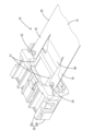
- FIG. 1 is a perspective view of a connector according to a first embodiment.
- FIG. 2 is an exploded perspective view of the connector.
- FIG. 3 is a perspective view of the flexible cable seen from below.
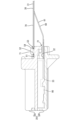
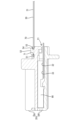
- FIG. 4 is a side view of the connector.
- FIG. 5 is a side sectional view showing a cut plane passing through the right boss pin.
- FIG. 6 is a side sectional view showing a cut plane passing through the left boss pin.
- FIG. 7 is a perspective view of the connector according to the second embodiment.
- FIG. 8 is an enlarged perspective view of the second component on the right side of FIG. 7.
- FIG. 9 is a plan view schematically showing a second component of a connector according to another embodiment.
- FIG. 10 is a plan view schematically showing a second component different from FIG. 9 according to another embodiment.
- Housing a flexible cable assembled to the housing; Equipped with The housing has a boss pin assembled to the flexible cable, The flexible cable is The main body and a first component extending from the main body toward the distal end and having a conductive path routed therein; a second component that extends from the main body toward the distal end and is assembled to the boss pin; has A breaking portion is provided in at least one of the boss pin and the second component, A connector in which the boss pin and the main body are disconnected from each other when the breaking portion breaks.
- the breakage portion is provided on at least one of the boss pin and the second component. can be broken.
- the rupture part breaks, the connection between the boss pin and the main body is released, so by understanding the release of this connection, a certain degree of separation can be made in the part of the flexible cable where the conductive path is provided. You can confirm that a load occurs.
- the narrow portion is narrower than the other portions of the second component other than the breakage portion, so it is easy to break. Therefore, by focusing on the narrow portion to release the connection between the boss pin and the main body portion, it becomes easier to identify the breakage at the breakage portion.
- the second component is provided with a locking hole that locks the boss pin,
- the connector according to [2], wherein the broken portion is a portion of the second component that includes a hole edge of the locking hole.
- the breaking strength of the broken portion can be adjusted by changing the positions of the boss pin and the locking hole.
- the breaking strength of the broken portion can be changed by changing the shape of the boss pin, making it easier to adjust the breaking strength of the broken portion.
- FIGS. 4 to 6 A first embodiment of the connector of the present disclosure will be described with reference to FIGS. 1 to 6. Note that the present invention is not limited to these examples, but is indicated by the scope of the claims, and is intended to include all changes within the meaning and scope equivalent to the scope of the claims.
- the left side in FIGS. 4 to 6 is defined as the front, and the right side is defined as the rear.
- the directions shown in FIGS. 4 to 6 are directly defined as upward and downward.
- the diagonally upper right side in FIG. 1 is defined as the left side
- the diagonally lower left side is defined as the right side.
- the connector 10 of the first embodiment includes a housing 20, a flexible cable 30, and a terminal fitting 90 (see FIGS. 5 and 6).
- the flexible cable 30 is connected to a terminal fitting 90 (see FIGS. 5 and 6) and assembled into the housing 20.
- the housing 20 includes a lower housing 40 and an upper housing 50.
- the housing 20 is constructed by combining a lower housing 40 and an upper housing 50.
- the lower housing 40 is made of synthetic resin. As shown in FIG. 2, the lower housing 40 has a flat shape that is long in the left-right direction.
- the lower housing 40 is provided with a plurality of terminal accommodating recesses 41.
- the terminal accommodating recess 41 has a long shape in the front-rear direction.
- the plurality of terminal accommodating recesses 41 are arranged in parallel in the left-right direction.
- a plurality of terminal insertion holes 42 are provided at the front end of the lower housing 40, respectively corresponding to the plurality of terminal accommodating recesses 41 and penetrating in the front-rear direction.
- the upper housing 50 is made of synthetic resin. As shown in FIG. 2, the upper housing 50 has a flat shape in the left-right direction. As shown in FIG. 1, a pair of left and right flat portions 51 are provided on the rear end side of the upper surface of the upper housing 50. As shown in FIG. The flat portion 51 has a horizontal exposed surface facing upward. A boss pin 52 is provided on the flat portion 51. The pair of left and right boss pins 52 are arranged in the upper housing 50 at positions that overlap in the left and right direction. The boss pin 52 is exposed to the outside.
- the boss pin 52 is assembled to the flexible cable 30.
- the boss pin 52 projects upward from the exposed surface of the flat portion 51.
- the boss pin 52 has a column portion 53 and an extension portion 54.
- the column portion 53 has a cylindrical shape extending upward from the flat portion 51.
- the extending portion 54 extends rearward from the tip of the column portion 53.
- the tip of the extending portion 54 has a curved shape that is convex toward the rear in plan view.
- the lower surface of the extending portion 54 is a horizontal surface.
- the housing 20 is provided with a slit-shaped opening 21 formed by the rear end of the lower housing 40 and the rear end of the upper housing 50.
- the opening 21 has an elongated shape in the left-right direction.
- a connection end 32 of a flexible cable 30, which will be described later, is inserted through the opening 21.
- a flat portion 51 and a boss pin 52 are provided above the opening 21 (on the upper housing 50 side).
- the flexible cable 30 has conductive paths and circuits formed on a base film that is a thin, flexible insulator. Specific examples of the flexible cable 30 include flexible printed circuits and flexible flat cables. A plurality of terminal fittings 90 are connected to the front end of the flexible cable 30 by welding or the like.
- the flexible cable 30 has a main body 31 , a first component 60 , a pair of second components 70 , and a connecting end 32 .
- the main body portion 31 constitutes a portion on the rear end side of the flexible cable 30 (the side opposite to the portion to which the terminal fitting 90 is connected).
- a conductive path (not shown) is wired in the main body portion 31 .
- the first component 60 projects from the main body 31 in the distal direction (forward) before being assembled to the housing 20.
- a conductive path (not shown) is wired in the first component 60 .
- a plurality of conductive paths (not shown) are arranged in the first component 60 so as to extend in the front-rear direction.
- a plurality of conductive paths (not shown) wired in the first component 60 are arranged in parallel in the left-right direction.
- the connecting end 32 protrudes from the first component 60 in the distal direction (forward).
- the connecting end portion 32 is wider in the left-right direction than the first component portion 60.
- the width of the connection end portion 32 in the left-right direction is the same as the width of the portion of the flexible cable 30 where the first component 60 and the pair of second components 70 are lined up.
- a plurality of comb-like tip portions 33 are provided at the tip of the connection end portion 32 .
- a terminal fitting 90 is connected to the tip portion 33 .
- the pair of second constituent parts 70 are juxtaposed with the first constituent part 60 in the left-right direction and protrude from the main body part 31 in the distal direction (forward) in a state before being assembled to the housing 20. .
- the pair of second constituent parts 70 are arranged on both left and right sides of the first constituent part 60. In the second component 70, no conductive path is wired.
- the second component 70 is assembled to the boss pin 52.
- the second component 70 is provided with a pair of locking holes 71 that respectively lock the pair of boss pins 52 .
- the locking hole 71 is provided at the tip (front end) of the second component 70.
- the main body portion 31, the first component portion 60, the pair of second component portions 70, and the connection end portion 32 can be formed by making a pair of L-shaped cuts 35 in a rectangular flexible cable.
- the pair of second components 70 are arranged on both sides of the first component 60 in a parallel direction (horizontal direction) of the conductive path (not shown) of the first component 60. It is located.
- the first component 60 and the second component 70 are separated from each other.
- the first component 60 and the second component 70 are arranged in parallel so that they can be individually contracted.
- a reinforcing plate 80 is provided in a portion of the flexible cable 30 excluding the first component 60. That is, the reinforcing plate 80 is provided on the main body portion 31, the pair of second constituent portions 70, and the connecting end portion 32. The reinforcing plate 80 is arranged on the lower surface of each of the main body part 31, the pair of second constituent parts 70, and the connecting end part 32.
- the column portion 53 of the boss pin 52 corresponds to an example of a “broken portion” in the present disclosure.
- breaking the column portion 53 the assembled state between the boss pin 52 and the second component 70 is released, and the connected state between the boss pin 52 and the main body portion 31 is released.
- the boss pin 52 is, for example, pulled rearward by the second component 70 and is broken when the column part 53 is divided into upper and lower parts.
- the breaking strength of the pillar portion 53 can be adjusted by changing the diameter of the pillar portion 53, for example. For example, the larger the diameter of the column 53, the greater the breaking strength of the column 53. The smaller the diameter of the column 53, the lower the breaking strength of the column 53. Therefore, it becomes easier to design the shape of the pillar portion 53.
- the connecting end 32 of the flexible cable 30 to which the terminal fitting 90 is connected is placed inside the lower housing 40 .
- the upper housing 50 is assembled to the lower housing 40.
- the housing 20 is formed, and the plurality of tip portions 33 of the connection end portions 32 and the terminal fittings 90 are housed in the housing 20.
- the rear end of the connection end 32 and the first component 60 and second component 70 are located further back than the opening 21 of the housing 20 .
- the locking holes 71 of the pair of second components 70 are respectively locked to the pair of boss pins 52.
- the plate surfaces of the pair of second components 70 are kept horizontal and are located on the same plane as the main body 31.
- the pair of second components 70 are not bent.
- the first component 60 is disposed below the main body 31 and the second component 70 .
- the first component 60 and the second component 70 constitute a step.
- the first component 60 includes a bent portion 61 that is bent relative to the main body 31 when the second component 70 is assembled to the boss pin 52 . Specifically, the bent portion 61 slopes downward toward the front.
- the connecting end 32 is positioned one step lower than the main body 31 and the second component 70.
- the plate surface of the connecting end portion 32 is arranged parallel to the plate surface of the main body portion 31 and the plate surface of the second component 70 .
- the boss pin 52 is provided with the pillar portion 53, which is an example of the "broken portion” of the present disclosure.
- the connection state between the boss pin 52 and the main body portion 31 is released.
- the column part 53 of the boss pin 52 can be broken.
- the boss pin 52 breaks, the connection state between the boss pin 52 and the main body part 31 is released. Therefore, by understanding the release of such a connection state, the connection state between the boss pin 52 and the main body part 31 is released, so that the part where the conductive path is provided in the flexible cable 30 can be It can be confirmed that a certain level of load is generated.
- the “break portion” of the present disclosure is provided on the boss pin 52. Therefore, the breaking strength of the boss pin 52 can be changed by changing the shape of the boss pin 52, and the breaking strength of the boss pin 52 can be easily adjusted.
- the conductive paths are arranged in parallel in the first component 60.
- a pair of second constituent parts 70 are arranged on both sides of the first constituent part 60 in the parallel direction of the conductive paths.
- Example 2 7 and 8 are drawings for explaining the connector of the second embodiment.
- Example 2 differs from Example 1 in the configuration of the broken portion.
- the other configurations are the same as in Example 1, and detailed explanation will be omitted.
- a connector 210 according to a second embodiment of the present disclosure will be described with reference to FIGS. 7 and 8.
- the second component 70 has a narrow portion 272.
- the narrow portion 272 is narrower in width in the left-right direction than other portions of the second component 70 other than the narrow portion 272 (portions adjacent to the narrow portion 272 at the front and rear, respectively).
- the narrow portion 272 corresponds to an example of a “broken portion” in the present disclosure.
- the narrow portion 272 is provided between the locking hole 71 and the main body portion 31 in the second component 70 .
- the narrow portion 272 is narrower than other portions of the second component 70 other than the narrow portion 272, it becomes easy to break. Therefore, by focusing on the narrow portion 272 to determine the release of the connection between the boss pin 52 and the main body portion 31, it becomes easier to identify the breakage of the second component 70.
- the narrow portion 272 of the second component 70 was illustrated as an example of the “broken portion” of the present disclosure, but other shaped portions may be used as the “broken portion” of the present disclosure.
- a narrow portion 372 including a pair of notches 373 provided in the second component 70 may be the “broken portion” of the present disclosure.
- a narrow portion 472 including a pair of through holes 473 provided in the second component 70 may be the “broken portion” of the present disclosure.
- the second component 70 having a constant width may be used as the "broken portion" of the present disclosure.
- the pillar portion 53 of the boss pin 52 corresponds to an example of the “rupture portion” of the present disclosure
- the portion of the second component 70 that includes the hole edge of the locking hole 71 is It may be a configuration that corresponds to an example of the "broken portion” of the present disclosure.
- the second component 70 is integrally formed with the main body 31, but it may be assembled into the main body 31 as a separate member from the main body 31.
- the housing 20 has a divided structure of the lower housing 40 and the upper housing 50, but may have an integral structure.
- the tip (extending portion 54) of the boss pin 52 has a shape that projects rearward, but it may have an umbrella shape that projects all around the axis.
Landscapes
- Details Of Connecting Devices For Male And Female Coupling (AREA)
- Coupling Device And Connection With Printed Circuit (AREA)
Abstract
Description
ハウジングと、
前記ハウジングに組み付けられるフレキシブルケーブルと、
を備え、
前記ハウジングは、前記フレキシブルケーブルに組み付けられるボスピンを有し、
前記フレキシブルケーブルは、
本体部と、
前記本体部から先端方向へ張り出し、導電路が配索される第1構成部と、
前記本体部から前記先端方向へ張り出し、前記ボスピンに組み付けられる第2構成部と、
を有し、
前記ボスピン及び前記第2構成部の少なくとも一方に、破断部が設けられ、
前記破断部が破断することで、前記ボスピンと前記本体部との連結状態が解除される。
以下では、本開示の実施形態が列記されて例示される。
前記ハウジングに組み付けられるフレキシブルケーブルと、
を備え、
前記ハウジングは、前記フレキシブルケーブルに組み付けられるボスピンを有し、
前記フレキシブルケーブルは、
本体部と、
前記本体部から先端方向へ張り出し、導電路が配索される第1構成部と、
前記本体部から前記先端方向へ張り出し、前記ボスピンに組み付けられる第2構成部と、
を有し、
前記ボスピン及び前記第2構成部の少なくとも一方に、破断部が設けられ、
前記破断部が破断することで、前記ボスピンと前記本体部との連結状態が解除されるコネクタ。
前記破断部は、前記第2構成部に設けられている〔1〕に記載のコネクタ。
前記破断部は、前記第2構成部における前記破断部以外の他の部分よりも幅狭な幅狭部として構成されている〔2〕に記載のコネクタ。
前記第2構成部には、前記ボスピンに係止する係止孔が設けられ、
前記破断部は、前記第2構成部のうち前記係止孔の孔縁部を含む部位である〔2〕に記載のコネクタ。
前記破断部は、前記ボスピンに設けられている〔1〕に記載のコネクタ。
前記第1構成部には、前記導電路が並列して配置され、
一対の前記第2構成部が、前記導電路の並列方向で前記第1構成部を挟んだ両側に配置されている〔1〕から〔5〕のいずれか一つに記載のコネクタ。
[実施例1]
本開示のコネクタを具体化した実施例1を、図1~図6を参照して説明する。なお、本発明はこれらの例示に限定されるものではなく、請求の範囲によって示され、請求の範囲と均等の意味および範囲内でのすべての変更が含まれることが意図される。本実施例1において、前後の方向については、図4~6における左方を前方と定義し、右方を後方と定義する。上下の方向については、図4~6にあらわれる向きをそのまま上方、下方と定義する。左右の方向については、図1における斜め右上方を左方と定義し、斜め左下方を右方と定義する。
図7、図8は、実施例2のコネクタを説明する図面である。実施例2は、破断部の構成が実施例1と異なっている。それ以外の構成は、実施例1と同じであり、詳しい説明を省略する。
本発明は、上記記述及び図面によって説明した実施例に限定されるものではなく、請求の範囲によって示される。本発明には、請求の範囲と均等の意味及び請求の範囲内でのすべての変更が含まれ、下記のような実施形態も含まれることが意図される。
20…ハウジング
21…開口部
30…フレキシブルケーブル
31…本体部
32…接続端部
33…先端部
35…切り込み
40…ロアハウジング
41…端子収容凹部
42…端子挿入孔
50…アッパハウジング
51…平坦部
52…ボスピン
53…柱部(破断部)
54…延出部
60…第1構成部
61…曲がり部
70…第2構成部
71…係止孔
80…補強板
90…端子金具
210…コネクタ
272…幅狭部(破断部)
372…幅狭部(破断部)
373…切り欠き部
472…幅狭部(破断部)
473…貫通孔
Claims (6)
- ハウジングと、
前記ハウジングに組み付けられるフレキシブルケーブルと、
を備え、
前記ハウジングは、前記フレキシブルケーブルに組み付けられるボスピンを有し、
前記フレキシブルケーブルは、
本体部と、
前記本体部から先端方向へ張り出し、導電路が配索される第1構成部と、
前記本体部から前記先端方向へ張り出し、前記ボスピンに組み付けられる第2構成部と、
を有し、
前記ボスピン及び前記第2構成部の少なくとも一方に、破断部が設けられ、
前記破断部が破断することで、前記ボスピンと前記本体部との連結状態が解除されるコネクタ。 - 前記破断部は、前記第2構成部に設けられている請求項1に記載のコネクタ。
- 前記破断部は、前記第2構成部における前記破断部以外の他の部分よりも幅狭な幅狭部として構成されている請求項2に記載のコネクタ。
- 前記第2構成部には、前記ボスピンに係止する係止孔が設けられ、
前記破断部は、前記第2構成部のうち前記係止孔の孔縁部を含む部位である請求項2に記載のコネクタ。 - 前記破断部は、前記ボスピンに設けられている請求項1に記載のコネクタ。
- 前記第1構成部には、前記導電路が並列して配置され、
一対の前記第2構成部が、前記導電路の並列方向で前記第1構成部を挟んだ両側に配置されている請求項1から請求項5のいずれか一項に記載のコネクタ。
Priority Applications (2)
| Application Number | Priority Date | Filing Date | Title |
|---|---|---|---|
| US18/859,171 US20250300379A1 (en) | 2022-04-27 | 2023-04-10 | Connector |
| CN202380034327.8A CN119054161A (zh) | 2022-04-27 | 2023-04-10 | 连接器 |
Applications Claiming Priority (2)
| Application Number | Priority Date | Filing Date | Title |
|---|---|---|---|
| JP2022073388A JP7703147B2 (ja) | 2022-04-27 | 2022-04-27 | コネクタ |
| JP2022-073388 | 2022-04-27 |
Publications (1)
| Publication Number | Publication Date |
|---|---|
| WO2023210320A1 true WO2023210320A1 (ja) | 2023-11-02 |
Family
ID=88518773
Family Applications (1)
| Application Number | Title | Priority Date | Filing Date |
|---|---|---|---|
| PCT/JP2023/014518 Ceased WO2023210320A1 (ja) | 2022-04-27 | 2023-04-10 | コネクタ |
Country Status (4)
| Country | Link |
|---|---|
| US (1) | US20250300379A1 (ja) |
| JP (1) | JP7703147B2 (ja) |
| CN (1) | CN119054161A (ja) |
| WO (1) | WO2023210320A1 (ja) |
Citations (2)
| Publication number | Priority date | Publication date | Assignee | Title |
|---|---|---|---|---|
| JPH05129046A (ja) * | 1991-10-31 | 1993-05-25 | Sumitomo Wiring Syst Ltd | フレキシブル配線板用コネクタ構造 |
| US20080146075A1 (en) * | 2006-12-11 | 2008-06-19 | Dell Products L.P. | Low Insertion Force Connector Coupling |
Family Cites Families (3)
| Publication number | Priority date | Publication date | Assignee | Title |
|---|---|---|---|---|
| JPH0644052Y2 (ja) * | 1989-08-25 | 1994-11-14 | 古河電気工業株式会社 | ブラシレス電気信号伝達装置 |
| JPH0515381U (ja) * | 1991-08-07 | 1993-02-26 | 古河電気工業株式会社 | ブラシレス電気信号伝達装置 |
| JP4383244B2 (ja) | 2004-05-13 | 2009-12-16 | 古河電気工業株式会社 | 回転コネクタ |
-
2022
- 2022-04-27 JP JP2022073388A patent/JP7703147B2/ja active Active
-
2023
- 2023-04-10 WO PCT/JP2023/014518 patent/WO2023210320A1/ja not_active Ceased
- 2023-04-10 CN CN202380034327.8A patent/CN119054161A/zh active Pending
- 2023-04-10 US US18/859,171 patent/US20250300379A1/en active Pending
Patent Citations (2)
| Publication number | Priority date | Publication date | Assignee | Title |
|---|---|---|---|---|
| JPH05129046A (ja) * | 1991-10-31 | 1993-05-25 | Sumitomo Wiring Syst Ltd | フレキシブル配線板用コネクタ構造 |
| US20080146075A1 (en) * | 2006-12-11 | 2008-06-19 | Dell Products L.P. | Low Insertion Force Connector Coupling |
Also Published As
| Publication number | Publication date |
|---|---|
| JP2023162770A (ja) | 2023-11-09 |
| CN119054161A (zh) | 2024-11-29 |
| JP7703147B2 (ja) | 2025-07-07 |
| US20250300379A1 (en) | 2025-09-25 |
Similar Documents
| Publication | Publication Date | Title |
|---|---|---|
| US6890193B2 (en) | Electrical connector improving both functions of magnetic shielding and ground connection | |
| JP4555329B2 (ja) | 基板対基板コネクタ | |
| JP6959876B2 (ja) | コネクタ | |
| CN111009757B (zh) | 连接器组件 | |
| KR101860641B1 (ko) | 커넥터 | |
| CN110932035B (zh) | 连接器和包括该连接器的连接器组件 | |
| KR20200050356A (ko) | 커넥터 및 커넥터 조립체 | |
| JP7010366B2 (ja) | コネクタ | |
| WO2020090398A1 (ja) | コネクタ | |
| CN115377719B (zh) | 端子、电线连接器及线对板连接器 | |
| CN114122790B (zh) | 连接器 | |
| EP4009446A1 (en) | Plug connector and connector set having same, and method for removing connector set | |
| CN119542835A (zh) | 连接器以及连接器组件 | |
| WO2019188739A1 (ja) | コネクタ | |
| JP2023162770A (ja) | コネクタ | |
| CN108604749B (zh) | 端子零件 | |
| JP6861690B2 (ja) | カバーとハウジングとの組付構造、及び、ヒュージブルリンクユニット | |
| JPWO2013168333A1 (ja) | 端子台および、これを用いた照明器具 | |
| KR100988789B1 (ko) | 터미널 | |
| WO2023210319A1 (ja) | コネクタ | |
| JP2019169401A (ja) | 基板用コネクタ | |
| WO2024053505A1 (ja) | 端子ユニット,雌端子,雄端子 | |
| JP6887458B2 (ja) | コネクタ | |
| KR102933759B1 (ko) | 퓨즈 및 퓨즈의 제조방법 | |
| US12472889B2 (en) | Electric wire holder |
Legal Events
| Date | Code | Title | Description |
|---|---|---|---|
| 121 | Ep: the epo has been informed by wipo that ep was designated in this application |
Ref document number: 23796066 Country of ref document: EP Kind code of ref document: A1 |
|
| WWE | Wipo information: entry into national phase |
Ref document number: 202380034327.8 Country of ref document: CN |
|
| WWE | Wipo information: entry into national phase |
Ref document number: 18859171 Country of ref document: US |
|
| NENP | Non-entry into the national phase |
Ref country code: DE |
|
| 122 | Ep: pct application non-entry in european phase |
Ref document number: 23796066 Country of ref document: EP Kind code of ref document: A1 |
|
| WWP | Wipo information: published in national office |
Ref document number: 18859171 Country of ref document: US |