WO2023210085A1 - 杭打ち装置 - Google Patents
杭打ち装置 Download PDFInfo
- Publication number
- WO2023210085A1 WO2023210085A1 PCT/JP2023/003278 JP2023003278W WO2023210085A1 WO 2023210085 A1 WO2023210085 A1 WO 2023210085A1 JP 2023003278 W JP2023003278 W JP 2023003278W WO 2023210085 A1 WO2023210085 A1 WO 2023210085A1
- Authority
- WO
- WIPO (PCT)
- Prior art keywords
- pile
- section
- driver
- control device
- piles
- Prior art date
- Legal status (The legal status is an assumption and is not a legal conclusion. Google has not performed a legal analysis and makes no representation as to the accuracy of the status listed.)
- Ceased
Links
Images




Classifications
-
- E—FIXED CONSTRUCTIONS
- E02—HYDRAULIC ENGINEERING; FOUNDATIONS; SOIL SHIFTING
- E02D—FOUNDATIONS; EXCAVATIONS; EMBANKMENTS; UNDERGROUND OR UNDERWATER STRUCTURES
- E02D7/00—Methods or apparatus for placing sheet pile bulkheads, piles, mouldpipes, or other moulds
- E02D7/20—Placing by pressure or pulling power
Definitions
- the present invention relates to a pile driving device, and more particularly, to a pile driving device that can save manpower.
- Patent Document 1 does not disclose anything about automation related to setting piles in a pile driver. Further, in Patent Document 1, pile driving is performed by an operator in the driver's seat of a pile driver, and remote control or unmanned operation is not envisioned.
- the first invention and the second invention aim to provide a pile driving device that can save manpower.
- the pile driving device includes: a main body device provided with a storage section for storing piles; a pile driver connected to the main body device for driving piles; and a supply device that supplies the pile driver to the pile driver.
- the pile driving device includes a main body device that travels by a traveling device, a pile driver that holds piles and drives the piles, a table portion connected to the pile driver, and the table portion. and a control device that controls the attitude of the pile driver using an actuator that drives the pile driver.
- the supply device supplies the piles stored in the storage section to the pile driver, so it is possible to realize a pile driver that can save manpower.
- the control device since the control device controls the attitude of the pile driver using the actuator that drives the table part, it is possible to realize a pile driver that can save manpower.
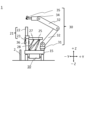
- FIG. 1 is a schematic diagram of a piling device according to the first embodiment, in which FIG. 1(a) is a top view, FIG. 1(b) is a front view, and FIG. 1(c) is a side view.
- FIG. 2 is a block diagram of a piling device and a transport vehicle according to the first embodiment. 3(a) is a top view, FIG. 3(b) is a front view, and FIG. 3(c) is a side view.
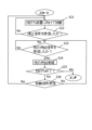
- FIG. 2 is a diagram showing how the piling device and the transport truck of the first embodiment are working together. It is a flowchart regarding pile driving executed by the control device of the first embodiment.
- FIG. 1 is a schematic diagram of a piling device according to the first embodiment, in which FIG. 1(a) is a top view, FIG. 1(b) is a front view, and FIG. 1(c) is a side view.
- FIG. 2 is a block diagram of a piling device and a transport vehicle according to the first
- FIG. 6(a) is a diagram showing how the piles stored in the storage section are transported to the piling section
- FIG. 6(a) is a diagram showing how the piles are attracted by an electromagnet
- FIG. 6(c) is a diagram showing how the second gripping section takes out the pile from the storage section
- FIG. 6(d) is a diagram showing how the supply device holds the pile.
- FIG. 6(f) is a diagram showing how the pile is being gripped by the first gripping part and the second gripping part
- FIG. ) is a diagram showing a state in which the grip of the pile by the second gripping section is released.
- FIG. 3 is a diagram illustrating a state in which the table section is retracted by the actuator section.
- FIG. 9(a) is a top view
- FIG. 9(b) is a front view
- FIG. 9(c) is a side view
- 10(a) is a top view
- FIG. 10(b) is a front view
- FIG. 10(c) is a side view.
- the pile driving device 1 according to a first embodiment of the present invention will be described in detail based on the accompanying drawings.
- the pile driving device 1 and the transport vehicle 100 cooperate to drive piles.
- the present invention is not limited to the embodiments described below.
- the vertical direction will be referred to as the Z direction
- the two axial directions perpendicular to each other in the horizontal plane will be referred to as the X direction and the Y direction.
- FIG. 1 is a schematic diagram of a pile driving device 1 representing the first embodiment, in which FIG. 1(a) is a top view, FIG. 1(b) is a front view, and FIG. 1(c) is a side view. It is a diagram.
- FIG. 2 is a block diagram of the pile driving device 1 and a transport vehicle 100, which will be described later. Hereinafter, the configuration of the pile driving device 1 will be explained using FIGS. 1 and 2.
- the pile driving device 1 includes a traveling device 10, a main body portion 15, a pile driver 20, a first supply device 30, a storage portion 36, a sensor portion 40, a first communication device 46, and a first memory 47. and a control device 50.
- the piling device 1 of the first embodiment is not provided with a driver's seat and performs a series of piling operations by remote control or automatic operation.
- the traveling device 10 has a traveling section 11 provided with an internal combustion engine or a traveling motor, an axle 12 rotated by the traveling section 11, and four wheels 13 connected to the axle 12.
- An in-wheel motor can be used as the travel motor.
- the driving motor can be driven by a fuel cell or the like. Note that two wheels 13 separated in the X direction may be wrapped around each other by crawler belts.
- the main body part 15 is a rectangular plate, and the traveling part 11 is connected to the lower surface, so that it can move in the XX plane.
- the main body part 15 holds the pile driver 20, the first supply device 30, and the storage part 36 on the upper surface.
- the pile driver 20 includes a pile driving section 21, a table section 25, and an actuator section 26, and is used to grip and drive a pile 2 (see FIG. 4).
- the pile driver 21 includes a jack 22 that extends the pile 2 along the ⁇ Z direction and drives the pile, and a first grip portion 23 that grips the pile 2.
- the jack 22 has a main body portion that accommodates hydraulic oil, and an extendable portion that extends and contracts in the Z direction. A main body portion of the jack 22 is held on a table portion 25.
- the first gripping section 23 has a chuck mechanism 23a for holding the pile 2 below the table section 25. The first gripping section 23 changes the chuck mechanism 23a from an open state to a closed state when gripping the pile 2, and changes the chuck mechanism 23a from a closed state to an open state when releasing the pile 2.
- this chuck mechanism 23a The opening and closing operations of this chuck mechanism 23a are performed by a hydraulic device (not shown).
- the first gripping part 23 changes the pile 2 from a gripping state to a non-gripping state using the chuck mechanism 23a, and grips the pile 2 again depending on the depth at which the pile 2 is driven. The position where it is held is changing.
- the chuck mechanism 23a should be used after gripping the pile 2 with the second gripping part 33. It is preferable that the grip be in a non-grip state.
- the table portion 25 is a rectangular plate, and has an opening 25a formed at one end ( ⁇ Y direction side).
- the table section 25 is connected to one end of an actuator section 26, which will be described later, and is connected to the main body section 15 via the actuator section 26.
- the opening 25a is formed such that it does not interfere with the pile 2 when the first gripping part 23 grips the pile 2 from above (+Z direction) or from the front side (from the ⁇ Y direction side to the +Y direction side). There is.
- the actuator section 26 is an actuator that controls the movement of the table section 25 with six degrees of freedom, and one end is connected to the table section 25 via a joint, and the other end is connected to the main body section 15 via a joint. It is connected to the.
- the actuator section 26 includes six link mechanisms 27 connected to the table section 25, six motors 28 connected to the main body section 15, and the aforementioned joint, and constitutes a parallel link mechanism. There is. Note that the actuator section 26 may employ a leveling mechanism or a gimbal mechanism instead of a parallel link mechanism.
- the actuator section 26 is provided with an encoder 29 (see FIG. 2) that detects the rotational position of the output shaft of each motor 28.
- the control device 50 controls the actuator section 26 so that the table section 25 becomes horizontal. Further, the control device 50 controls the control device 50 so that when the pile driving device 1 is moved, the driven pile 2 is connected to the pile driving portion 21 (for example, the first gripping portion 23) or the table portion 25 near the opening 25a of the table portion 25. If interference occurs, interference with the driven stake 2 can be avoided by retracting the table section 25 in the +Y direction using the actuator section 26 as shown in FIG.
- the first supply device 30 conveys the piles 2 stored in the storage section 36 to the pile driver 20. Note that if the transport vehicle 100 is not provided with a second supply device 120 to be described later, the first supply device 30 is configured to transport the piles 2 from the transport vehicle 100 to the storage section 36 or the pile driver 20. Good too.
- the first supply device 30 includes a rotating section 31, an arm section 32, and a second gripping section 33.
- the turning section 31 is provided on the main body section 15 side, has a bearing (not shown) and a motor (not shown), and turns the first supply device 30 around the Z-axis.
- the arm portion 32 rotates the first supply device 30 using a plurality of joints.
- the first supply device 30 can move or position the second gripping section 33 to any three-dimensional position by turning the turning section 31 and rotating the arm section 32.
- the arm portion 32 rotates to a position where the second gripping portion 33 can hold the stake 2 above the center of gravity of the stake 2 (+Z side).
- the first supply device 30 can stabilize the posture of the pile 2 and move the pile 2.
- the length of the pile 2 is stored in a first memory 47, which will be described later, and the control device 50 calculates the center of gravity of the pile 2 from the length of the pile 2, and also calculates the position of the center of gravity of the pile 2 based on the top surface of the main body 15. 32 is moved above the center of gravity of the pile 2.
- the second gripping part 33 grips the pile 2, and has an electromagnet 34 and an opening/closing part 35 that can be opened and closed.
- the electromagnet 34 first grips the pile 2 by magnetic attraction, and then the opening/closing section in the open state is turned into the closed state by a motor (not shown), and the pile 2 is mechanically moved. grasp it.
- the gripping by magnetic attraction by the electromagnet 34 may be continued, or the gripping by magnetic attraction may be canceled by cutting off the power supply.
- the electromagnet 34 is provided below the opening/closing part 35 in FIG. 1, the electromagnet 34 may be provided above the opening/closing part 35, or the electromagnet 34 may be provided inside the opening/closing part 35.
- the electromagnet 34 electromagnetically grips the pile 2 by moving the electromagnet 34 close to the pile 2 by the rotation of the rotating part 31 and the rotation of the arm part 32, and by the rotation of the arm part 32, the pile 2 is held by the electromagnet 34. This can be done by bringing 2 into contact with the electromagnet 34.
- the storage section 36 is provided in the main body section 15 and stores the pile 2 through an inner hollow portion.
- the number of stakes 2 stored in the storage section 36 may be one or more.
- the storage section 36 has one end fixed to the main body section 15 and the other end has a reverse tapered shape whose diameter decreases toward the one end side (-Z side).
- the hollow part also has a reverse tapered shape. This reverse tapered shape makes it easy to guide the pile 2 into the storage section 36 from above the storage section 36.
- the sensor unit 40 performs various types of sensing, and in the first embodiment, as shown in FIG. 44 and an accelerometer 45.
- the sensor section 40 is shown collectively on the top surface of the table section 25, but a part of it (for example, the imaging device 44) is provided on the bottom surface of the table section 25. Good too.
- the attitude detection unit 41 detects the attitude of the pile driver 20, and in particular detects the attitude of the pile driver 21 that grips the pile 2 and drives the pile. As described above, the jack 22 of the piling section 21 is held by the table section 25, so in the first embodiment, by providing the posture detecting section 41 on the top surface of the table section 25, the posture detecting section 41 The attitude of the pile driver 21 is detected. Note that the attitude detection section 41 may be provided in the piling section 21. Note that the attitude detection section 41 can use an inclinometer, a spirit level, or the like.
- the detection device 42 detects the situation around the pile driver 20, and uses LiDAR in the first embodiment.
- LiDAR scans pulsed electromagnetic waves such as ultraviolet light, visible light, or near-infrared light, and based on the emitted light and scattered light, determines the distance to the object, the shape of the object, the material of the object, and the color of the object.
- It is a sensor that detects information such as
- the detection device 42 measures a reference portion serving as a reference for piling or a pile that has been driven, detects a distance from the transport vehicle 100, and detects the distance between a plurality of piles of the transport vehicle 100. 2 shape recognition. Note that the measurement of the reference portion by the detection device 42 is performed before piling is performed.
- the detection device 42 is provided on the top surface of the table portion 25, but may be provided on the bottom surface of the table portion 25, or may be provided on the main body portion 15. Moreover, the number of detection devices 42 may be one, or a plurality of them may be provided.
- the first GNSS 43 measures the position of the pile driving device 1 using artificial satellites.
- the first GNSS 43 is provided on the top surface of the table section 25, but it may be provided anywhere on the pile driving device 1 as long as it is in a position where it can receive positioning signals from artificial satellites.
- the imaging device 44 is a digital camera that has a lens, an image sensor, an image processing engine, etc., and captures moving images and still images.
- the imaging device 44 is provided on the lower surface of the table portion 25, and is used to image a mark indicating a position where stake driving is to be performed. Note that the imaging device 44 may be provided on the top surface of the table section 25, or may be provided on the top surface and the bottom surface of the table section 25, respectively.
- the accelerometer 45 detects the acceleration that acts on the table part 25 when the pile driver 20 is driven, and the acceleration that acts on the table part 25 when the traveling device 10 travels.
- the accelerometer 45 any type such as mechanical type, optical type, semiconductor type, etc. can be used.
- the accelerometer 45 is provided in the table section 25 and detects the acceleration of the table section 25 in the Z-axis direction; however, the accelerometer 45 is not limited to this; Directional acceleration may also be detected. Further, the number of accelerometers 45 to be provided may be one or more than one.
- the control device 50 detects the acceleration by the detection device 42 or by the imaging device. 44 may not be performed.
- the control device 50 detects the posture of the table section 25 using the posture detection section 41 and drives the actuator section 26.
- the posture of the pile 2 may be controlled to prevent the pile 2 from being piled in an inclined manner.
- the detection error of the posture detection unit 41 when an acceleration exceeding a threshold is applied may be measured or calculated in advance through experiments, and this detection error may be stored in the first memory 47 as a correction table. good. Thereby, the control device 50 can correct the detection error of the posture detection section 41 when an acceleration exceeding the threshold is applied. Further, the detection error of the posture detection section 41 when an acceleration equal to or less than a threshold value is applied may also be stored in the first memory 47.
- the first communication device 46 is a wireless communication unit that accesses a second communication device 128 of the transport vehicle 100, which will be described later, and a wide area network such as the Internet.
- the first communication device 46 communicates with the second communication device 128 to transmit the position of the piling device 1 to the transport vehicle 100 and to receive the position of the transport vehicle 100.
- the first communication device 46 can communicate with a central control device, a data center, etc. located far from the piling site using the aforementioned wide area network.
- the first memory 47 is a nonvolatile memory (for example, a flash memory), and is used to store various data (for example, coordinate data regarding the pile driving position) and programs for driving the pile driving device 1, and to remotely control the pile driving device 1. It stores various data and programs for autonomous driving. Further, the first memory 47 stores data on the distance at which the first supply device 30 can receive the pile 2 of the transport vehicle 100, the length of the pile 2, and the like.
- the control device 50 is a control device that includes a CPU and controls the entire pile driving device 1. The control of the pile driving device 1 by the control device 50 will be described later using the flowchart of FIG. 5.
- FIG. 3 is a schematic diagram of the transport vehicle 100 representing the first embodiment, in which FIG. 3(a) is a top view, FIG. 3(b) is a front view, and FIG. 3(c) is a side view. It is.
- the configuration of the transport vehicle 100 will be described below using the block diagram of FIG. 2 and FIG. 3.
- the transport trolley 100 of the first embodiment is not provided with a driver's seat and performs a series of transport operations by remote control or automatic operation.
- the transport truck 100 is a truck that transports a plurality of piles 2 in a horizontal state, and cooperates with the pile driving device 1 to supply the piles 2 to the pile driving device 1. Note that the transport vehicle 100 may be configured to transport the pile 2 in a state where the pile 2 is erected.
- the transport truck 100 includes a traveling device 110, a main body 115, a second supply device 120, a second GNSS 127, a second communication device 128, a second memory 129, and a truck side control device 130. There is.
- the traveling device 110 has a traveling section 111 provided with an internal combustion engine or a traveling motor, an axle 112 rotated by the traveling section 111, and four wheels 113 connected to the axle 112.
- An in-wheel motor can be used as the travel motor.
- the driving motor can be driven by a fuel cell or the like. Note that two wheels 113 separated from each other in the X direction may be wrapped around each other by crawler belts.
- the traveling device 10 and the traveling device 110 are made common, the manufacturing cost of the piling device 1 and the transport trolley 100 can be reduced, and replacement parts are also common, which reduces inventory management costs and maintenance costs. be able to.
- the main body part 115 is a rectangular plate, and the traveling device 110 is connected to the lower surface thereof, so that the main body part 115 can move on the XX plane.
- the main body portion 115 holds the pile 2 and the second supply device 120 on its upper surface.
- the main body part 115 is provided with fences (not shown) on all sides to prevent the stakes 2 from falling from the main body part 115.
- the manufacturing cost of the pile driving device 1 and the transport trolley 100 can be reduced, and replacement parts are also common, thereby reducing inventory management costs and maintenance costs. be able to.
- FIG. 4 is a diagram showing how the piling device 1 and the transport vehicle 100 of the first embodiment are working together.
- the second supply device 120 supplies the piles 2 mounted on the transport vehicle 100 to the storage section 36.
- the second supply device 120 may deliver the pile 2 mounted on the transport vehicle 100 to the first supply device 30 or the pile driver 20.
- the first supply device 30 of the pile driving device 1 supplies the piles 2 mounted on the transport vehicle 100 to the storage section 36
- the second supply device 120 can be omitted.
- the first supply device 30 can be omitted.
- the second supply device 120 includes a rotating section 121, an arm section 122, and a third gripping section 123 including an electromagnet 124 and an opening/closing section 125.
- the rotating section 121, the arm section 122, and the third gripping section 123 can have the same configuration as the rotating section 31, the arm section 32, and the second gripping section 33, so a description thereof will be omitted.
- the arm portion 122 is rotated to a position where the third gripping portion 123 can hold the stake 2 above the center of gravity of the stake 2 (+Z side).
- the manufacturing cost of the pile driving device 1 and the transport trolley 100 can be reduced, and since the replacement parts are also common, inventory management costs and maintenance can be reduced. Costs can be reduced.
- the second GNSS 127 measures the position of the transport vehicle 100 using artificial satellites.
- the second GNSS 127 is provided on the upper surface of the main body 115, but it may be provided anywhere on the transport vehicle 100 as long as it can receive positioning signals from artificial satellites.
- the second communication device 128 is a wireless communication unit that accesses the first communication device 46 and a wide area network such as the Internet. In this embodiment, the second communication device 128 communicates with the first communication device 46 to transmit the position of the transport vehicle 100 to the transport vehicle 100 and receive the position of the piling device 1 .
- the second memory 129 is a nonvolatile memory (for example, a flash memory), and stores various data and programs for driving the transportation vehicle 100 and various data and programs for remotely controlling or automatically driving the transportation vehicle 100. is memorized.
- the second memory 129 also stores data such as the presence or absence of the second supply device 120, the length of the pile 2, and when the second supply device 120 is present, the second supply device 120 delivers the pile 2 to the storage section 36. It stores data such as possible distances.
- the truck-side control device 130 is a control device that includes a CPU and controls the entire transportation truck 1001. The control of the transport trolley 100 by the trolley side control device 130 will be described later using the flowchart of FIG.
- FIG. 5 is a flowchart regarding pile driving performed by the control device 50 of the first embodiment.
- FIG. 6 is a diagram showing how the pile 2 stored in the storage section 36 is conveyed to the piling section 21. Note that in FIG. 6, illustration of the sensor section 40 is omitted to avoid complicating the drawing. The explanation will be continued below using FIGS. 5 and 6.
- the control device 50 determines whether the piles 2 can be supplied from the transport vehicle 100 (step S1). In the first embodiment, it is assumed that the transport vehicle 100 is provided with a second supply device 120.
- the control device 50 communicates with the transport vehicle 100, recognizes the data on the distance at which the second supply device 120 can deliver the pile 2 to the storage section 36, and uses the LiDAR of the detection device 42 to transfer the second supply device 120 to the second supply device 120. detects whether the transport vehicle 100 has approached the storage part 36 to a distance where the pile 2 can be delivered.
- the control device 50 repeats the determination in step S1 based on the detection result of the detection device 42 until the piles 2 can be supplied from the transport vehicle 100.
- the control device 50 determines that the piles can be supplied from the transport vehicle 100, and proceeds to step S2.
- the control device 50 causes the pile driving device 1 to supply the piles 2 loaded on the transport truck 100 (step S2).
- the pile driving device 1 causes the pile driving device 1 to supply the piles 2 loaded on the transport truck 100 (step S2).
- the pile 2 is not supplied to either the pile driver 20 or the storage section 36 of the pile driver 1.
- the control device 50 communicates with the transport truck 100 and instructs the truck-side control device 130 to supply the piles 2.
- the truck-side control device 130 controls the second supply device 120 to store one pile 2 in the storage section 36 (see FIG. 4).
- the control device 50 controls the first supply device 30 to move the second gripping section 33 to the pile 2 by turning the turning section 31 and rotating the arm section 32.
- the piles 2 in the storage section 36 are gripped by the second gripping section 33 as they approach each other.
- the control device 50 moves the pile 2 toward the pile driver 20 by turning the turning section 31 and rotating the arm section 32.
- the control device 50 instructs the truck-side control device 130 to supply the pile 2 again.
- the control device 50 uses the detection device 42 to recognize the shapes of the plurality of piles 2 loaded on the transport trolley 100, detects the piles 2 in positions that are easy to transport, and transmits this detection result to the trolley side control device. 130.
- control device 50 may determine whether the stake 2 is stored in the storage section 36 based on the detection result of the detection device 42 or the imaging result of the imaging device 44.
- control device 50 provides a weight sensor (not shown) in the storage section 36, and determines whether the pile 2 is stored in the storage section 36 based on the detection result of this weight sensor. You may decide whether or not to do so.
- the control device 50 determines whether the first gripping section 23 is gripping the pile 2 (step S3). In the above description, the pile 2 is moving toward the pile driver 20, so the control device 50 makes the determination in step S3 No and proceeds to step S4.
- the control device 50 causes the pile 2 to approach the chuck mechanism 23a of the first gripping part 23 by turning the turning part 31 and rotating the arm part 32, and holds the pile 2 by the chuck mechanism 23a of the first gripping part 23. (Step S4).
- control device 50 attracts the pile 2 with the electromagnet 34 as shown in FIG. 6(a), and closes the opening/closing part 35 as shown in FIG. 6(b) to hold the pile 2 in the second grip. It is gripped by the portion 33.
- the control device 50 takes out the stake 2 from the storage section 36 using the second gripping section 33 as shown in FIG. Move towards 21.
- the control device 50 causes the first gripping section 23 to grip the pile 2 while the second gripping section 33 grips the pile 2 as shown in FIG. 6(e), and as shown in FIG. The grip of the pile 2 by the second grip part 33 is released.
- the control device 50 stops supplying current to the electromagnet 34 so that no attraction force acts on the pile 2, and changes the opening/closing part 35 from the closed state to the open state. As a result, the grip of the pile 2 by the second grip part 33 is released.
- the control device 50 determines whether the driving position of the pile 2 held by the first gripping section 23 is recognized (step S5).
- the piling device 1 has arrived at the place where piling is to be performed, it is assumed that the piling device 1 does not recognize the piling position, and the control device 50 proceeds to step S6.
- the control device 50 recognizes the pile driving position (step S6).
- the control device 50 detects this mark using the imaging device 44 and recognizes the position of driving a stake.
- the control device 50 may recognize the position of driving a stake based on the positioning result of the first GNSS 43. Note that when positioning by the first GNSS 43 is not possible, the control device 50 performs stakeout based on the survey results of the reference section performed in advance and the position (coordinates) for stakeout stored in the first memory 47. Can recognize location.
- the control device 50 drives the actuator section 26 on the XX plane to match the recognized pile driving position and the pile driver 20.
- the position can be adjusted.
- the control device 50 can reduce the time required for this adjustment by adjusting the recognized pile driving position and the position of the pile driver 20 by using the actuator section 26 instead of the traveling device 10.
- the control device 50 may drive the pile driver 20 in the Z direction by the actuator section 26 in this adjustment.
- the control device 50 Based on the detection result of the posture detection section 41, the control device 50 operates the actuator section 26 so that the table section 25 becomes horizontal, and furthermore, the posture of the pile 2 gripped by the first gripping section 23 becomes vertical. drive Thereby, the control device 50 can make the posture of the pile 2 substantially vertical before the pile driver 20 starts driving the pile. Note that when driving the pile 2 at an angle, the control device 50 may drive the actuator unit 26 so that the table unit 25 has a predetermined amount of inclination.
- control device 50 After adjusting the attitude of the pile 2 by the actuator unit 26, the control device 50 causes the pile driver 20 to drive the pile 2 held by the first grip unit 23 (step S7).
- the control device 50 drives the pile 2 into the ground by extending the jack 22.
- the control device 50 determines whether or not the attitude of the pile 2 needs to be corrected during the pile driving process by the pile driver 20 (step S8).
- the control device 50 monitors the detection result of the attitude detection unit 41 during the pile driving process by the pile driver 20, and determines whether the attitude of the pile 2 is inclined by a predetermined amount (for example, several degrees).
- a predetermined amount for example, several degrees.
- the first gripping section 23 changes the pile 2 from the gripping state to the non-gripping state using the chuck mechanism 23a, and grips the pile 2 again, depending on the depth at which the pile 2 is driven. The position where the stake 2 is held is changed.
- the table portion 25 maintains the posture of the pile 2 during pile driving, and since the jack 22 is not driven, vibrations caused by the driving of the jack 22 do not act on the table portion 25. For this reason, it is preferable that the control device 50 monitors the detection result of the posture detection unit 41 during this non-gripping state and determines whether the posture of the pile 2 is tilted by a predetermined amount (for example, several degrees). .
- control device 50 may detect the attitude of the pile 2 using LiDAR of the detection device 42 in the above-mentioned non-gripping state.
- the control device 50 adjusts the attitude of the pile 2 by the actuator section 26 (step S9).
- the control device 50 uses the non-gripping state to adjust the posture of the pile 2 by the actuator section 26.
- the control device 50 reduces the speed at which the jack 22 is extended by about 10% to 50% when adjusting the posture of the pile 2 by the actuator section 26. You may also do so.
- the vibrations acting on the table portion 25 can be reduced, and therefore the error in detecting the posture by the posture detecting section 41 can be reduced.
- time for adjusting the posture of the pile 2 by the actuator section 26 can be secured. In this way, since the attitude of the pile 2 is detected during a series of pile driving processes, the pile driving time can be shortened. Note that the posture adjustment of the pile 2 during pile driving may be performed multiple times during pile driving.
- the control device 50 determines whether the driving of the pile 2 has been completed (step S10).
- the control device 50 detects the pile 2 with the detection device 42 and detects whether the pile 2 has been driven to a predetermined depth.
- the detection device 42 may detect the upper surface of the stake 2, or may provide a mark on the stake 2 and detect this mark.
- the control device 50 determines that the pile driving has ended and proceeds to step S11.
- the control device 50 executes data processing upon completion of stake driving (step S11).
- the control device 50 detects the length of the pile 2 protruding from the ground surface using the detection device 42 and the imaging device 44, and calculates the driving depth of the pile 2 based on the length of the pile 2. Further, the control device 50 detects the posture of the staked pile 2 by detecting the posture of the pile driving section 21 by the posture detection section 41 while the first gripping section 23 grips the staked pile 2. (tilt) is detected. Further, the control device 50 calculates the coordinates at which the pile 2 is driven from the positioning result obtained by the first GNSS 43 and the mechanical positional relationship between the first GNSS 43 and the pile driving unit 21.
- the control device 50 stores the data detected or calculated in step S11 in the first memory 47, or communicates the data detected or calculated in step S11 to a central control device or the like located far from the piling site via the network using the first communication device 46. Send this data to a data center, etc.
- the pile driving data can be checked immediately after driving the pile, so the central control unit or data center can check whether or not the position adjustment of the next pile 2 to be driven needs to be changed, and whether or not the driven pile 2 needs to be corrected. etc. can be recognized almost in real time.
- the control device 50 proceeds to step S12.
- the control device 50 determines whether there is a next stakeout based on the coordinate data regarding the stakeout position stored in the first memory 47 (step S12). When there is a next pile driving, the control device 50 starts moving toward the next pile driving position, and repeats step S1 and subsequent steps. In addition, when the table part 25 or the pile driver 20 interferes with the driven pile 2, the control device 50 may drive the actuator part 26 to retract the table part 25. The presence or absence of this interference can be detected by the detection device 42.
- FIG. 7 is a diagram showing how the table section 25 is retracted by the actuator section 26.
- the control device 50 can prevent the table portion 25 and the pile driver 20 from interfering with the pile 2 that has been driven while the pile driving device 1 is moving.
- the control device 50 may control the attitude of the first supply device 30 so that the table portion 25 does not interfere with the first supply device 30 when the table portion 25 is retracted.
- the control device 50 controls how the first supply device 30 and the first gripping section 23 can control the piles 2 stored in the storage section 36. If the first gripping section 23 grips the pile, the next pile driving can be carried out promptly.
- the moving speed of the pile driving device 1 is low, about 0.5 Km/h to 2.0 Km/h, and the transport vehicle 100 is moving within a predetermined distance (for example, within 0.5 to 2 meters) of the pile driving device.
- the second supply device 120 may supply the pile 2 to the storage section 36 during this movement. Instead, the second supply device 120 supplies the piles 2 to the storage section 36 while the pile driving device 1 recognizes the next pile driving position or while driving the pile. You can also do this.
- the control device 50 transmits a signal indicating that the pile driving has been completed to the transport vehicle 100, and the flowchart is end.
- the first supply device 30 supplies the piles 2 stored in the storage section 36 to the pile driver 20, so the pile driver 1 that can save labor can be used. It can be realized.
- the control device 50 controls the attitude of the pile driver 20 using the actuator section 26 that drives the table section 25, so a pile driver capable of saving manpower is realized. can do.
- FIG. 8 is a flowchart regarding the supply of piles executed by the truck-side control device 130 of the first embodiment. It is assumed that this flowchart starts when a movement signal from the control device 50 of the pile driving device 1 is received.
- the truck-side control device 130 receives the movement signal from the control device 50 and starts moving toward the pile driving device 1 (step S21).
- the trolley-side control device 130 receives the positioning result (for example, latitude and longitude) determined by the first GNSS 43 of the pile driving device 1, and starts movement by the traveling device 110.
- the truck-side control device 130 determines whether a stop signal has been received from the control device 50 (step S22).
- the control device 50 receives the positioning signal received by the second GNSS 127 of the transport vehicle 100, guides the transport vehicle 100 to the piling device 1, and causes the transport vehicle 100 to approach the piling device 1.
- the control device 50 may guide the transportation vehicle 100 to the piling device 1 by detecting the transportation vehicle 100 with the detection device 42, and may also cause the transportation vehicle 100 to approach the piling device 1.
- the control device 50 determines that the second supply device 120 can supply the piles 2, it transmits a movement stop signal to the transport vehicle 100.
- the trolley-side control device 130 repeats the determination in step S22 until it receives the movement stop signal, and when it receives the movement stop signal, it stops the transporter 100 and sends a signal to the piling device 1 indicating that the transporter 100 has stopped. After transmitting the information, the process proceeds to step S23.
- the truck-side control device 130 determines whether or not the pile 2 supply signal has been received from the control device 50 (step S23).
- the control device 50 receives a signal from the transportation vehicle 100 indicating that the transportation vehicle 100 has stopped, it transmits a supply signal for the piles 2 to the transportation vehicle 100.
- the trolley-side control device 130 repeats the determination in step S23 until receiving the supply signal for the pile 2, and upon receiving the supply signal for the pile 2, proceeds to step S24.
- the truck-side control device 130 causes the second supply device 120 to supply the piles 2 to the storage section 36 (step S24).
- the trolley side control device 130 holds the pile 2 by attracting the pile 2 with the electromagnet 124 and closing the opening/closing part 125. Thereby, the third gripping section 123 can grip the pile 2.
- the truck-side control device 130 moves the pile 2 toward the storage section 36 using the second supply device 120, and then stores the pile 2 in the storage section 36 (see FIG. 4). Then, the truck-side control device 130 releases the grip of the pile 2 by the third grip part 123.
- the trolley-side control device 130 stops the supply of current to the electromagnet 124 so that no attraction force acts on the pile 2, and also changes the opening/closing part 125 from the closed state to the open state to close the third grip part 123. Release the grip on the stake 2 by the
- the truck-side control device 130 determines whether the series of pile driving by the pile driving device 1 has been completed (step S25). If the determination in step S12 of the flowchart of FIG. 5 is No, the truck-side control device 130 determines whether or not it has received a signal indicating that piling has been completed, which is transmitted by the control device 50. When the trolley side control device 130 receives this signal, it assumes that the piles 2 are not being supplied to the pile driving device 1 and ends this flowchart.
- the truck-side control device 130 determines whether a movement signal has been received from the pile driving device 1 (step S26). This step S26 determines whether to supply the piles 2 to the pile driving device 1 at the current location of the transport cart 100, or whether to follow the pile driving device 1 that has started moving toward the next pile driving location. This is the step to judge.
- the vehicle-side control device 130 If the vehicle-side control device 130 has not received the movement signal, it repeats steps S23 and subsequent steps in order to supply the pile 2 at the current location. On the other hand, when the trolley-side control device 130 receives the movement signal, it moves following the piling device 1, so it repeats steps S21 and subsequent steps. In either case, the truck-side control device 130 repeats this flowchart until the determination in step S25 becomes YES.
- a detection device 42 equipped with LiDAR may be provided on the transport vehicle 100 side, and the pile driving device 1 may be recognized by this detection device 42 to make the determination in step S22.
- the second embodiment will be described below with reference to FIGS. 9 and 10, and the same components as those in the first embodiment will be denoted by the same reference numerals, and the explanation thereof will be omitted or simplified.
- the configurations of the two pile drivers 20, the configurations of the two first feeding devices 30, and the configurations of the two second feeding devices 120 are the same, so the component of one is indicated by the letter a after the code. , the other component will be explained by adding b after the reference numeral.
- the pile driver 20a, the first supply device 30a, the pile driver 20b, and the first supply device 30b are provided in the order from the -X direction to the +X direction.
- the pile driver 20a, the first supply device 30a, the first supply device 30b, and the pile driver 20b may be provided in this order, or may be arranged in any other order.
- the control device 50 shortens the construction period required for a series of pile driving by driving the two piles 2 almost simultaneously using the pile driver 20a and the pile driver 20b.
- the interval between the pile drivers 20a and 20b (for example, the interval in the X direction) can be adjusted by driving at least one of the actuator section 26a and the actuator section 26b.
- a second supply device 120a is provided at one end side (-X direction side) of the main body 115, and a second supply device 120b is provided at the other end side (+X direction side).
- the truck-side control device 130 controls the supply of the piles 2 to the pile driving device 1 by controlling the drive of the second supply device 120a and the second supply device 120b so that they do not interfere.
- the pile driver 1 includes two pile drivers 20, two first supply devices 30, and two storage units 36, and the transport trolley 100 is the same as the transport trolley of the first embodiment. It may be set to 100. That is, if the transport vehicle 100 of the first embodiment can supply the piles 2 to the storage portion 36a and the storage portion 36b within the time when the pile driving device 1 prepares for pile driving, the transport vehicle 100 of the first embodiment is used. be able to.
- control device 50 controls the pile driver 20a, the pile driver 20b, the first supply device 30a, and the first supply device 30b according to the flowchart in FIG. I can do it.
- the central control device 50 transmits these data to the central control device, data center, etc. after the pile driving machine 20a and the pile driver 20b finish driving each pile, the central control device or data center can drive the piles.
- the spacing and slope of two driven piles can be recognized almost in real time.
- the central control device and the data center can recognize in almost real time whether or not the position adjustment of the next two piles 2 to be driven needs to be changed, and whether or not the driven pile 2 needs to be corrected.
- truck-side control device 130 can control the second supply device 120a and the second supply device 120b according to the flowchart in FIG.
- a plurality of stakes 2 may be stored in one storage section 36.
- a series of pile driving is performed using a plurality of pile drivers 20 and a plurality of first supply devices 30, so that the workability of pile driving can be improved.
- the number of first supply devices 30 may be one.
- the pile driving device 1 may be a manned type driven by a person
- the transport cart 100 may be a manned type driven by a person.
- part of the flowcharts in FIGS. 5 and 8 may be performed by an operator.
- the first embodiment and the second embodiment may be combined as appropriate.
- Pile driving device 2 Pile 10 Traveling device 15 Main body portion 20 Pile driver 21 Pile driving portion 22 Jack 23 First grip portion 25 Table portion 26 Actuator portion 27 Link mechanism 28 Motor 30 First supply device 31 Swivel portion 32 Arm portion 33 Second gripping section 34 Electromagnet 35 Opening/closing section 36 Storage section 40 Sensor section 41 Attitude detection section 42 Detection device 50 Control device 100 Transport trolley 110 Traveling device 115 Main body section 120 Second supply device 121 Swivel section 122 Arm section 123 Third gripping section 124 Electromagnet 125 Opening/closing part 130 Truck side control device
Landscapes
- Engineering & Computer Science (AREA)
- Life Sciences & Earth Sciences (AREA)
- General Life Sciences & Earth Sciences (AREA)
- Mining & Mineral Resources (AREA)
- Paleontology (AREA)
- Civil Engineering (AREA)
- General Engineering & Computer Science (AREA)
- Structural Engineering (AREA)
- Earth Drilling (AREA)
Priority Applications (1)
| Application Number | Priority Date | Filing Date | Title |
|---|---|---|---|
| JP2024517842A JPWO2023210085A1 (https=) | 2022-04-26 | 2023-02-01 |
Applications Claiming Priority (2)
| Application Number | Priority Date | Filing Date | Title |
|---|---|---|---|
| US202263334726P | 2022-04-26 | 2022-04-26 | |
| US63/334,726 | 2022-04-26 |
Publications (1)
| Publication Number | Publication Date |
|---|---|
| WO2023210085A1 true WO2023210085A1 (ja) | 2023-11-02 |
Family
ID=88518308
Family Applications (1)
| Application Number | Title | Priority Date | Filing Date |
|---|---|---|---|
| PCT/JP2023/003278 Ceased WO2023210085A1 (ja) | 2022-04-26 | 2023-02-01 | 杭打ち装置 |
Country Status (2)
| Country | Link |
|---|---|
| JP (1) | JPWO2023210085A1 (https=) |
| WO (1) | WO2023210085A1 (https=) |
Citations (10)
| Publication number | Priority date | Publication date | Assignee | Title |
|---|---|---|---|---|
| JPS5761850B2 (https=) * | 1974-03-19 | 1982-12-27 | Shinnippon Seitetsu Kk | |
| JPH0423921B2 (https=) * | 1985-06-07 | 1992-04-23 | Giken Seisakusho Kk | |
| JPH0447736B2 (https=) * | 1985-04-26 | 1992-08-04 | Giken Seisakusho Kk | |
| JP2521583Y2 (ja) * | 1992-07-24 | 1996-12-25 | 鹿島建設株式会社 | 杭打装置の移動装置 |
| JP2631962B2 (ja) * | 1994-08-10 | 1997-07-16 | 株式会社技研製作所 | 杭圧入引抜機 |
| JPH09302657A (ja) * | 1996-05-20 | 1997-11-25 | Kawasaki Steel Corp | 土留め機材用カートリッジ及び土留め機材用運搬台車 |
| JP2001200538A (ja) * | 2000-01-18 | 2001-07-27 | Komatsu Ltd | 杭埋設機の埋設工法及びその制御装置 |
| JP2011202450A (ja) * | 2010-03-26 | 2011-10-13 | Nishimatsu Constr Co Ltd | 杭打設システム |
| JP2020159106A (ja) * | 2019-03-27 | 2020-10-01 | 住友重機械建機クレーン株式会社 | 杭抜き装置 |
| WO2021014425A1 (en) * | 2019-07-24 | 2021-01-28 | Geosec S.R.L. | Device for driving piles into the ground |
-
2023
- 2023-02-01 JP JP2024517842A patent/JPWO2023210085A1/ja active Pending
- 2023-02-01 WO PCT/JP2023/003278 patent/WO2023210085A1/ja not_active Ceased
Patent Citations (10)
| Publication number | Priority date | Publication date | Assignee | Title |
|---|---|---|---|---|
| JPS5761850B2 (https=) * | 1974-03-19 | 1982-12-27 | Shinnippon Seitetsu Kk | |
| JPH0447736B2 (https=) * | 1985-04-26 | 1992-08-04 | Giken Seisakusho Kk | |
| JPH0423921B2 (https=) * | 1985-06-07 | 1992-04-23 | Giken Seisakusho Kk | |
| JP2521583Y2 (ja) * | 1992-07-24 | 1996-12-25 | 鹿島建設株式会社 | 杭打装置の移動装置 |
| JP2631962B2 (ja) * | 1994-08-10 | 1997-07-16 | 株式会社技研製作所 | 杭圧入引抜機 |
| JPH09302657A (ja) * | 1996-05-20 | 1997-11-25 | Kawasaki Steel Corp | 土留め機材用カートリッジ及び土留め機材用運搬台車 |
| JP2001200538A (ja) * | 2000-01-18 | 2001-07-27 | Komatsu Ltd | 杭埋設機の埋設工法及びその制御装置 |
| JP2011202450A (ja) * | 2010-03-26 | 2011-10-13 | Nishimatsu Constr Co Ltd | 杭打設システム |
| JP2020159106A (ja) * | 2019-03-27 | 2020-10-01 | 住友重機械建機クレーン株式会社 | 杭抜き装置 |
| WO2021014425A1 (en) * | 2019-07-24 | 2021-01-28 | Geosec S.R.L. | Device for driving piles into the ground |
Also Published As
| Publication number | Publication date |
|---|---|
| JPWO2023210085A1 (https=) | 2023-11-02 |
Similar Documents
| Publication | Publication Date | Title |
|---|---|---|
| JP7755041B2 (ja) | 移動装置および無人飛行装置 | |
| JP7410251B2 (ja) | 建設機械のアシスト方法 | |
| JP7402360B2 (ja) | 建設機械 | |
| KR20210135295A (ko) | 작업 기계, 시스템 및 작업 기계의 제어 방법 | |
| US12497276B2 (en) | Autonomous load moving electric vehicle | |
| JP2017041165A (ja) | 自律走行装置 | |
| JP7549164B2 (ja) | 建設機械システム | |
| JP7216582B2 (ja) | 車両の走行制御システム | |
| WO2023210085A1 (ja) | 杭打ち装置 | |
| US20250223773A1 (en) | Piling Machine | |
| JP2024053172A (ja) | 自律作業システム及び自律作業機 | |
| KR102670522B1 (ko) | 다중 관성측정장치와 카메라 센서 융합기반 위치 인식을 이용한 로더 용량별 결합이 가능한 자율주행 무인 운반차 | |
| JP6813251B2 (ja) | 無人飛行体を用いた運搬システム | |
| CN118458387A (zh) | 一种智能运输机器人及运输方法 | |
| NL2015909B1 (en) | Vehicle, system and method for displacing feed. | |
| CN111984011B (zh) | 一种多控制升降运输车 | |
| AU2024288904A1 (en) | Transfer vehicle, system and method for guiding a vehicle into a cargo space of a transfer vehicle | |
| KR20240130431A (ko) | 전투 차량 및 탄약을 공급하는 탄약 운반 차량 | |
| CN111032979A (zh) | 用于机动车辆运输的行驶平台 |
Legal Events
| Date | Code | Title | Description |
|---|---|---|---|
| 121 | Ep: the epo has been informed by wipo that ep was designated in this application |
Ref document number: 23795833 Country of ref document: EP Kind code of ref document: A1 |
|
| ENP | Entry into the national phase |
Ref document number: 2024517842 Country of ref document: JP Kind code of ref document: A |
|
| NENP | Non-entry into the national phase |
Ref country code: DE |
|
| 122 | Ep: pct application non-entry in european phase |
Ref document number: 23795833 Country of ref document: EP Kind code of ref document: A1 |