WO2023209977A1 - 情報処理方法、情報処理装置、及びプログラム - Google Patents
情報処理方法、情報処理装置、及びプログラム Download PDFInfo
- Publication number
- WO2023209977A1 WO2023209977A1 PCT/JP2022/019368 JP2022019368W WO2023209977A1 WO 2023209977 A1 WO2023209977 A1 WO 2023209977A1 JP 2022019368 W JP2022019368 W JP 2022019368W WO 2023209977 A1 WO2023209977 A1 WO 2023209977A1
- Authority
- WO
- WIPO (PCT)
- Prior art keywords
- display
- layer
- widget
- information processing
- scroll
- Prior art date
- Legal status (The legal status is an assumption and is not a legal conclusion. Google has not performed a legal analysis and makes no representation as to the accuracy of the status listed.)
- Ceased
Links
Images




Classifications
-
- G—PHYSICS
- G06—COMPUTING OR CALCULATING; COUNTING
- G06F—ELECTRIC DIGITAL DATA PROCESSING
- G06F3/00—Input arrangements for transferring data to be processed into a form capable of being handled by the computer; Output arrangements for transferring data from processing unit to output unit, e.g. interface arrangements
- G06F3/01—Input arrangements or combined input and output arrangements for interaction between user and computer
- G06F3/048—Interaction techniques based on graphical user interfaces [GUI]
- G06F3/0481—Interaction techniques based on graphical user interfaces [GUI] based on specific properties of the displayed interaction object or a metaphor-based environment, e.g. interaction with desktop elements like windows or icons, or assisted by a cursor's changing behaviour or appearance
-
- G—PHYSICS
- G06—COMPUTING OR CALCULATING; COUNTING
- G06F—ELECTRIC DIGITAL DATA PROCESSING
- G06F3/00—Input arrangements for transferring data to be processed into a form capable of being handled by the computer; Output arrangements for transferring data from processing unit to output unit, e.g. interface arrangements
- G06F3/01—Input arrangements or combined input and output arrangements for interaction between user and computer
- G06F3/048—Interaction techniques based on graphical user interfaces [GUI]
- G06F3/0484—Interaction techniques based on graphical user interfaces [GUI] for the control of specific functions or operations, e.g. selecting or manipulating an object, an image or a displayed text element, setting a parameter value or selecting a range
- G06F3/0485—Scrolling or panning
-
- G—PHYSICS
- G06—COMPUTING OR CALCULATING; COUNTING
- G06F—ELECTRIC DIGITAL DATA PROCESSING
- G06F3/00—Input arrangements for transferring data to be processed into a form capable of being handled by the computer; Output arrangements for transferring data from processing unit to output unit, e.g. interface arrangements
- G06F3/01—Input arrangements or combined input and output arrangements for interaction between user and computer
- G06F3/048—Interaction techniques based on graphical user interfaces [GUI]
- G06F3/0481—Interaction techniques based on graphical user interfaces [GUI] based on specific properties of the displayed interaction object or a metaphor-based environment, e.g. interaction with desktop elements like windows or icons, or assisted by a cursor's changing behaviour or appearance
- G06F3/04817—Interaction techniques based on graphical user interfaces [GUI] based on specific properties of the displayed interaction object or a metaphor-based environment, e.g. interaction with desktop elements like windows or icons, or assisted by a cursor's changing behaviour or appearance using icons
-
- G—PHYSICS
- G06—COMPUTING OR CALCULATING; COUNTING
- G06F—ELECTRIC DIGITAL DATA PROCESSING
- G06F3/00—Input arrangements for transferring data to be processed into a form capable of being handled by the computer; Output arrangements for transferring data from processing unit to output unit, e.g. interface arrangements
- G06F3/01—Input arrangements or combined input and output arrangements for interaction between user and computer
- G06F3/048—Interaction techniques based on graphical user interfaces [GUI]
- G06F3/0481—Interaction techniques based on graphical user interfaces [GUI] based on specific properties of the displayed interaction object or a metaphor-based environment, e.g. interaction with desktop elements like windows or icons, or assisted by a cursor's changing behaviour or appearance
- G06F3/0483—Interaction with page-structured environments, e.g. book metaphor
-
- G—PHYSICS
- G06—COMPUTING OR CALCULATING; COUNTING
- G06F—ELECTRIC DIGITAL DATA PROCESSING
- G06F3/00—Input arrangements for transferring data to be processed into a form capable of being handled by the computer; Output arrangements for transferring data from processing unit to output unit, e.g. interface arrangements
- G06F3/01—Input arrangements or combined input and output arrangements for interaction between user and computer
- G06F3/048—Interaction techniques based on graphical user interfaces [GUI]
- G06F3/0484—Interaction techniques based on graphical user interfaces [GUI] for the control of specific functions or operations, e.g. selecting or manipulating an object, an image or a displayed text element, setting a parameter value or selecting a range
- G06F3/04845—Interaction techniques based on graphical user interfaces [GUI] for the control of specific functions or operations, e.g. selecting or manipulating an object, an image or a displayed text element, setting a parameter value or selecting a range for image manipulation, e.g. dragging, rotation, expansion or change of colour
-
- G—PHYSICS
- G06—COMPUTING OR CALCULATING; COUNTING
- G06F—ELECTRIC DIGITAL DATA PROCESSING
- G06F3/00—Input arrangements for transferring data to be processed into a form capable of being handled by the computer; Output arrangements for transferring data from processing unit to output unit, e.g. interface arrangements
- G06F3/01—Input arrangements or combined input and output arrangements for interaction between user and computer
- G06F3/048—Interaction techniques based on graphical user interfaces [GUI]
- G06F3/0487—Interaction techniques based on graphical user interfaces [GUI] using specific features provided by the input device, e.g. functions controlled by the rotation of a mouse with dual sensing arrangements, or of the nature of the input device, e.g. tap gestures based on pressure sensed by a digitiser
- G06F3/0488—Interaction techniques based on graphical user interfaces [GUI] using specific features provided by the input device, e.g. functions controlled by the rotation of a mouse with dual sensing arrangements, or of the nature of the input device, e.g. tap gestures based on pressure sensed by a digitiser using a touch-screen or digitiser, e.g. input of commands through traced gestures
-
- G—PHYSICS
- G06—COMPUTING OR CALCULATING; COUNTING
- G06F—ELECTRIC DIGITAL DATA PROCESSING
- G06F2203/00—Indexing scheme relating to G06F3/00 - G06F3/048
- G06F2203/048—Indexing scheme relating to G06F3/048
- G06F2203/04803—Split screen, i.e. subdividing the display area or the window area into separate subareas
-
- G—PHYSICS
- G06—COMPUTING OR CALCULATING; COUNTING
- G06F—ELECTRIC DIGITAL DATA PROCESSING
- G06F2203/00—Indexing scheme relating to G06F3/00 - G06F3/048
- G06F2203/048—Indexing scheme relating to G06F3/048
- G06F2203/04804—Transparency, e.g. transparent or translucent windows
Definitions
- the present invention relates to an information processing method, an information processing device, and a program for controlling screen display of a touch panel display.
- the display method includes the steps of displaying at least one object on a screen, receiving user input to receive a direction for scrolling the at least one object, and responsive to a scroll speed corresponding to the received user input. , changing the size of the displayed area of the at least one object within the screen, and scrolling the at least one object in accordance with the scrolling method.
- the problem to be solved by the present invention is to provide an information processing method, an information processing device, and a program that suppress a user's discomfort with the display of an object in a scene where the screen display scrolls.
- the present invention detects an operation on a screen display including a first layer located in the front and a second layer located behind the first layer, and when the operation on the screen display is a scroll operation, scrolls the first layer.
- a scroll process is executed and an object placed in the first layer scrolls and reaches the edge of the screen display, the object that has reached the edge of the screen display is moved from the first layer to the second layer.
- FIG. 1 is a schematic configuration diagram of an information presentation device according to an embodiment.
- FIG. 1 is a diagram for explaining an information presentation device and a display according to the present embodiment.
- FIG. 3 is a diagram for explaining a main layer and a sub layer.
- FIG. 3 is a diagram for explaining processing by a widget migration unit and a sub-layer display control unit. It is an example of a flowchart showing the procedure of information processing according to the present embodiment.
- FIG. 7 is a diagram illustrating how the screen changes when a scroll operation is performed by the information processing device according to the comparative example.
- FIG. 3 is a diagram illustrating how the screen changes by the information processing device according to the embodiment when a scroll operation is performed.
- 8 is a diagram showing a continuation of the screen transition shown in FIG. 7.
- FIG. FIG. 3 is a diagram for explaining processing of the information processing device according to the present embodiment.
- FIG. 1 is a schematic diagram of the configuration of an information presentation device 100 according to the present embodiment.
- the information presentation device 100 is a device that is installed inside a vehicle and presents various information to passengers.
- the information presentation device 100 displays, for example, an operation screen for operating in-vehicle devices such as a navigation device, an audio device, and an air conditioner, and an operation screen for in-vehicle devices that are operating in response to operations by a passenger (vehicle route guidance, etc.). (e.g., map information, etc.) to show the crew the necessary information.
- the information presentation device 100 includes a display 1, a storage device 2, and an information processing device 10.
- the display 1 is a touch panel display and is mounted on the vehicle.
- the touch panel type display 1 is equipped with a pressure sensor, and detects the pressing force applied to the display 1 during a touch operation from a resistance value, voltage, etc.
- the mechanism of the pressure-sensitive sensor is not particularly limited, and any pressure-sensitive sensor mechanism known at the time of filing can be used as appropriate.
- the touch panel is not limited to a pressure-sensitive type, and may be of other types such as an electrostatic type.
- the display 1 may be a touch panel type display 1, and the type of the display 1 is not particularly limited.
- the display 1 may be a liquid crystal display or an organic electro-luminescence (OEL) display.
- the display 1 is placed on the dashboard between the driver's seat and the passenger's seat. Further, the display 1 is disposed in front of the driver's seat and the front passenger's seat so that the driver sitting in the driver's seat and the passenger sitting in the front passenger's seat (hereinafter referred to as front passenger) can reach the display 1.
- front passenger the driver sitting in the driver's seat and the passenger sitting in the front passenger's seat
- FIG. 2 is a diagram for explaining the information presentation device 100 and display 1 according to the present embodiment.
- FIG. 2A is a diagram showing the interior of a vehicle, and is an example of the information presentation device 100 and the display 1.
- the display 1 is provided on the left side of the steering wheel when FIG. 2A is viewed from the front.
- the display 1 is a display that is elongated in the horizontal direction as well as in the vertical direction.
- the driver and the passenger in the passenger seat input the details of the operation to the information presentation device 100 to the display 1 by performing a touch operation on the display 1 .
- the touch operation is an operation of touching an object displayed on the display 1 with a finger or the like.
- FIG. 2(B) is an enlarged view of the display 1 shown in FIG. 2(A), and is a diagram for explaining widgets that are operated by the occupant.
- a widget will be described as an example of an object to be operated by a passenger.
- a widget is a shortcut to an application software displayed on the home screen.
- the screen display D of the display 1 includes a widget display area WA and a fixed display area PA (permanent area) provided around the widget display area WA.
- Widget display area WA and fixed display area PA are adjacent to each other.
- the screen display D is an area on the display 1 that can be operated by the driver or the front passenger.
- the widget display area WA is an area where widgets W1 to W4 are displayed. In the widget display area WA, the widgets W1 to W4 are scrolled to the left or to the right when FIG. 2B is viewed from the front, in accordance with the scrolling operation of the main layer, which will be described later.
- the fixed display area PA is an area where specific information is displayed regardless of a scroll operation on the screen display D.
- the fixed display area PA displays the set temperature of the driver's side air conditioner, the set temperature of the front passenger side air conditioner, the current time, and icons indicating application software other than widgets.
- application software may be abbreviated as “application” or “application,” but these terms have the same meaning.
- widgets W1 to W4 are displayed side by side from left to right when FIG. 2(B) is viewed from the front.
- the widget includes an icon portion that concisely represents the application in an identifiable manner, a panel portion that displays information regarding the application software, and a shadow portion (not shown) that displays shadows at the boundaries of the icon portion and the boundaries of the panel portion.
- the panel section is wider than the icon section, and the icon section is displayed superimposed on the right side of the center line of the panel section.
- the widget W1 includes a panel portion p1, an icon portion i1 and a shadow portion s1 that are displayed superimposed on the panel portion p1.
- the shadow portion s1 is provided at the boundary of the icon portion i1 and the boundary of the panel portion p1.
- the shadow area is a type of visual effect that makes it easier to distinguish between the boundaries of the icon area and the boundaries of the panel area.
- a description of widgets W2 to W4 will be omitted, and the description of widget W1 will be used.
- the target applications of the widget are not particularly limited, and examples include a calling application, a search application, a weather forecast application, a map application, a music application, and the like.
- Touch operations include tap (touch the screen once), double tap (touch the screen twice), long tap (touch the screen for a long time), and swipe (slide the finger that touched the screen on the screen). (trace your finger)), flick (move the finger that touched the screen in a quick flicking motion), pinch in/pinch out (touch the screen with two fingers and move them closer/away), Drag (hold down an item on the screen and slide it), Drop (hold down an item with your finger and then let go of the screen), Scroll (touch the screen without taking your finger off the screen) (moving your finger up and down or left and right).
- the touch operation may be so-called hovering, in which a finger or the like is brought close to the screen display, without directly touching the screen display of the display 1.
- the touch operation method is not limited to these, and other methods may be used.
- the display 1 When the driver or passenger performs a touch operation on the display 1, the display 1 detects the position of the touch operation on the screen display and outputs information on the detected position to the information processing device 10. Further, the display 1 outputs the position of the touch operation as well as the detection result by the pressure-sensitive sensor to the information processing device 10 . On the other hand, a control command for displaying image data is input to the display 1 from the information processing device 10 .
- the display 1 displays one or more screens based on image data.
- the storage device 2 is a storage device such as an HDD (Hard Disk Drive) or an SSD (Solid State Drive).
- the storage device 2 stores various data regarding the information presentation device 100.
- the storage device 2 stores image data of an icon portion, image data of a panel portion, image data of a shadow portion, etc. as information regarding the widget.
- the storage device 2 outputs stored data to the information processing device 10 in response to a control command from the information processing device 10.
- the storage device 2 also deletes data, updates existing data, stores new data, etc. in response to control commands from the information processing device 10.
- the information processing device 10 is composed of a computer equipped with hardware and software, and specifically includes a ROM (Read Only Memory) that stores programs, and a CPU (Central Processing Unit) that executes the programs stored in the ROM. ) and a RAM (Random Access Memory) that functions as an accessible storage device.
- ROM Read Only Memory
- CPU Central Processing Unit
- RAM Random Access Memory
- an MPU Micro Processing Unit
- DSP Digital Signal Processor
- ASIC Application Specific Integrated Circuit
- FPGA Field Programmable Gate Array
- the controller 11 shown in FIG. 1 is a main body that executes an information processing method according to the present invention, which will be described later, and corresponds to a computer.
- the location where the program is stored is not limited to the ROM.
- the program can be read by a computer and may be stored in a portable computer-readable recording medium (eg, disk media, flash memory, etc.).
- the information processing device 10 downloads a program from a computer-readable recording medium and executes the downloaded program.
- the information processing device 10 may be configured to include only an operating circuit and download the program from outside.
- the controller 11 of the information processing device 10 includes, as functional blocks, an operation detection section 12, a main layer display control section 13, a widget display position detection section 14, a widget transition section 15, and a sub layer display control section 13. It has a display control section 16.
- the operation detection unit 12 detects a touch operation performed on the display 1 based on information input from the display 1.
- the operation detection unit 12 receives input from the display 1 of the touch-operated position information on the display 1 and the detection results of the pressure sensor (resistance value, voltage, etc. indicating the pressing force). For example, the operation detection unit 12 determines whether the operation on the display 1 is a tap operation, a double tap operation, a long tap operation, a swipe operation, a flick operation, a pinch-in/pinch-out operation, or a drag operation based on information input from the display 1. , a drop operation, and a scroll operation.
- the number of touch operations detected by the operation detection unit 12 is not particularly limited; for example, the operation detection unit 12 detects that the touch operations on the display 1 are two types of touch operations: a drag operation and a scroll operation. You may.
- a known detection method known at the time of filing of this application can be used.
- the operation detection unit 12 detects the operation direction of the touch operation based on information input from the display 1. For example, when the operation detection unit 12 determines that the operation on the display 1 is a scroll operation based on information input from the display 1, the operation detection unit 12 detects the direction of the scroll operation.
- the scroll operation direction corresponds to the direction in which the driver or the front passenger moves their finger on the screen in the scroll operation. Examples of the scroll operation direction include an up-down direction (a top-to-bottom direction, a bottom-to-top direction), and a left-right direction (a left-to-right direction, a right-to-left direction).
- the touch operation detection process executed by the operation detection unit 12 includes a process of detecting a scroll operation direction in a scroll operation.
- the operation detection unit 12 detects the operation speed of the touch operation based on information input from the display 1. For example, when the operation detection unit 12 determines that the operation on the display 1 is a scroll operation based on information input from the display 1, the operation detection unit 12 detects the operation speed of the scroll operation.
- the operation speed of the scroll operation corresponds to the speed of finger movement when the driver or passenger in the passenger seat moves his or her finger vertically or horizontally on the screen in the scroll operation.
- the touch operation detection process executed by the operation detection unit 12 includes a process of detecting the operation speed of the scroll operation.
- the main layer display control unit 13 controls the display of the main layer of the screen display on the display 1 in response to the touch operation detected by the operation detection unit 12.
- the screen display of the display 1 is configured to include a main layer located in the front and a sub layer located behind the main layer. When the screen display of the display 1 is viewed from the front, the main layer is located in front of the sub layer.
- FIG. 3 is a diagram for explaining the main layer and sublayer.
- FIG. 3(A) is a schematic diagram of the widget display area WA shown in FIG. 2(B).
- FIG. 3(A) components similar to those shown in FIG. 2(B) are designated by the same reference numerals as those shown in FIG. 2(B).
- the x-axis indicates the vehicle width direction (left-right direction)
- the y-axis indicates the depth in the vehicle's traveling direction (forward direction)
- the z-axis indicates the height direction (vertical direction). ing.
- the widget display area WA includes a main layer L1 which is a display layer along the x-axis and the z-axis, and a main layer L1 located on the positive side of the y-axis from the main layer L1. and a sublayer L2 which is a display layer along the z-axis.
- the main layer L1 and the sublayer L2 form a hierarchical structure in which the main layer L1 is the front surface and the sublayer L2 is the rear surface.
- the sizes of the main layer L1 and the sublayer L2 are not particularly limited, in this embodiment, the main layer L1 and the sublayer L2 will be described as display layers having the same size.
- the main layer L1 and the sublayer L2 have a size that allows the widgets W1 to W4 to be arranged side by side in the left-right direction.
- FIG. 3(A) When widgets W1 to W4 are arranged on the main layer L1 in the positional relationship shown in FIG. 3(A), a screen display D (widget display area WA) shown in FIG. 2(B) is displayed on the display 1. be done.
- widgets W1 to W4 belong to the main layer L1 as shown in FIG. 3(B).
- Widgets belonging to the main layer L1 are displayed on the display 1 as widgets arranged in the main layer L1.
- FIG. 3(B) is a diagram for explaining the affiliations of widgets corresponding to the screen display of FIG. 3(A). The roles and functions played by the sublayer L2 will be described later.
- the main layer display control unit 13 executes a scroll process to scroll the main layer.
- the main layer display control unit 13 outputs to the display 1 a control command for scrolling the main layer in a direction corresponding to the scroll operation direction detected by the operation detection unit 12 as a scroll process.
- the main layer display control unit 13 issues a control command to scroll the main layer L1 from left to right. is output to display 1.
- the display 1 displays a screen in which the entire main layer L1 including the widgets W1 to W4 scrolls from left to right. Further, in the example of FIG.
- the main layer display control unit 13 when the main layer display control unit 13 detects a scroll operation direction from right to left along the x-axis, the main layer display control unit 13 issues a control command to scroll the main layer L1 from right to left. is output to display 1. As a result, the display 1 displays a screen in which the entire main layer L1 including the widgets W1 to W4 scrolls from right to left. In this embodiment, the left and right direction will be described as an example of the scroll operation direction.
- the main layer display control unit 13 executes, as a scroll process, a process of delaying the scroll display of the icon part of the widget with respect to the scroll display of the panel part.
- a scroll process a process of delaying the scroll display of the icon part of the widget with respect to the scroll display of the panel part.
- the main layer display control unit 13 outputs a control command to the display 1 to cause the icon part of the widget to scroll later than the panel part.
- the display 1 displays a screen in which the icon section scrolls later than the panel section after the scroll operation is performed.
- the display 1 displays an animation screen in which the icon section follows the panel section.
- the scrolling process executed by the main layer display control unit 13 includes a process of delaying the scrolling display of the icon part of the widget with respect to the scrolling display of the panel part.
- the main layer display control unit 13 executes, as a scroll process, a process of changing the scroll display speed of the widget according to the operation speed of the scroll operation.
- the scroll display speed corresponds to the moving speed of the widget on the screen.
- the main layer display control unit 13 outputs a control command to the display 1 to increase the scroll display speed of the widget as the scroll operation speed becomes faster.
- the display 1 displays a screen in which the faster the scroll operation speed, the faster the widget moves on the screen.
- the scroll process executed by the main layer display control unit 13 includes a process of changing the scroll display speed of the widget according to the operation speed of the scroll operation.
- the scrolling process executed by the main layer display control unit 13 includes a process of increasing the scrolling display speed of the widget as the scrolling operation speed becomes faster.
- the main layer display control unit 13 also scrolls the sub layer in conjunction with the main layer as a scroll process. That is, the main layer display control unit 13 outputs to the display 1 a control command for scrolling the sub layer in the same scroll direction as the scroll direction of the main layer and at the same display speed as the scroll display speed of the main layer.
- the main layer display control unit 13 executes display control other than scroll display in response to a touch operation on the display 1. For example, when the operation on the display 1 is a tap operation and the tapped object is a specific widget, the main layer display control unit 13 issues a control command to display the screen of the application corresponding to the tapped widget. is output to display 1. Note that the tap operation processing is only an example, and the main layer display control unit 13 can perform display control other than the known scroll display known at the time of filing of the present application in response to a touch operation on the display 1.
- the widget display position detection unit 14 detects the display position of the widget on the display 1 when the main layer display control unit 13 starts scroll processing.
- the widget display position detection unit 14 determines whether the widget arranged in the main layer has been scrolled by the scrolling process and has reached the end of the screen display of the display 1.
- the screen display of the display 1 includes a fixed display area in addition to the widget display area (see FIG. 2(B))
- the widget display position detection unit 14 detects a fixed display area as an edge of the screen display. Set the boundaries between the widget display area and fixed display area.
- the widget display position detection unit 14 determines whether the panel part of the widget has reached the end of the screen display.
- the widget transition unit 15 determines that the widget has reached the end of the screen display. Execute the migration process to migrate the widget from the main layer to the sub layer. In this embodiment, for a widget whose panel section has reached the boundary between the widget display area and the fixed display area, the widget migration section 15 moves the entire widget including the panel section, icon section, and shadow section from the main layer to the sub layer. Execute the migration process to migrate to . As a migration process, the widget migration unit 15 outputs to the display 1 a control command for changing the affiliation of a widget that has reached the end of the screen display from the main layer to the sub layer.
- the widget migration unit 15 sends a control command to the display 1 to display the widget that has migrated to the sub layer while maintaining the relationship between the scroll display of the panel part and the scroll display of the icon part in the main layer.
- the migration process executed by the widget migration unit 15 is to change the affiliation of a widget that has reached the edge of the screen display from the main layer to the sub layer, thereby displaying the widget on the display 1 as a widget placed in the sub layer. This includes processing to Furthermore, the migration process executed by the widget migration unit 15 includes processing to display the widget that has migrated to the sub layer on the display while maintaining the relationship between the scroll display of the panel part and the scroll display of the icon part in the main layer. .
- the widget migration unit 15 arranges the widgets on the sublayer so that the widgets that have migrated to the sublayer are displayed inside the edges of the screen display.
- the widget migration unit 15 moves the widget that has migrated to the sub layer between the widget display area and the fixed display area.
- the widget migration unit 15 outputs to the display 1 a control command for displaying the widget that has migrated to the sub layer inside the edge of the screen display.
- the migration processing executed by the widget migration unit 15 includes processing for displaying the widget that has migrated to the sub layer inside the edge of the screen display.
- FIG. 4 is a diagram for explaining processing by the widget migration section 15 and the sub-layer display control section 16, which will be described later.
- FIG. 4A shows that after a scroll operation from left to right is performed on the screen display shown in FIG.
- FIG. 3 is a diagram showing how the boundary has been reached.
- FIG. 4(B) is a diagram illustrating the screen display shown in FIG. 4(A) after the transition process by the widget transition unit 15 and the display control process by the sub-layer display control unit 16, which will be described later, are executed. be.
- FIG. 4C is a diagram for explaining migration processing by the widget migration unit 15.
- the widget transition unit 15 As shown in FIG. 4A, when the end of the panel p4 located in the scroll direction reaches the boundary between the widget display area WA and the fixed display area PA, the widget transition unit 15 As shown in (C), a control command for changing the affiliation of the widget W4 from the main layer L1 to the sub layer L2 is output to the display 1. Thereby, as shown in FIG. 4(B), the widget W4 is displayed on the display 1 as a widget placed on the sub layer L2, that is, a widget located behind the main layer L1. In addition, in the scroll display on the main layer L1, if the icon part i4 scrolls behind the panel part p4, the widget transition part 15 displays the scroll display of the panel part p4 and the scroll display of the icon part i4 in the main layer L1.
- a control command for moving to the sub layer and displaying the widget W4 is output to the display 1 while maintaining the relationship with the widget W4.
- the panel part on the sub layer L2 is p4 and icon portion i4 are displayed.
- the widget migration unit 15 outputs to the display 1 a control command for displaying the widget W4 that has migrated to the sub layer inside the boundary between the widget display area WA and the fixed display area PA.
- the widget W4 that has moved to the sub layer L2 is displayed inside the widget display area WA.
- the sub-layer display control unit 16 controls the display of the sub-layer on the screen of the display 1.
- the sub-layer display control unit 16 executes a transparency change process and a size change process on the widget transferred from the main layer to the sub layer by the widget transfer unit 15.
- the transparency change process is a process of changing the transparency of the widget compared to before it is transferred to the sub layer.
- the size change process is a process of changing the transparency of the widget compared to before it is transferred to the sub layer.
- the sub-layer display control unit 16 outputs a control command to the display 1 to increase the transparency of the widget that has been transferred to the sub-layer compared to before the widget has been transferred to the sub-layer, as the transparency change process. .
- the absolute value of the transparency of the widget is not particularly limited, and the sub-layer display control unit 16 sets the transparency of the widget that has been transferred to the sub-layer to be relatively higher than that before the widget is transferred to the sub-layer.
- a control command for this purpose is output to the display 1.
- the widget W4 that has moved to the sub layer L2 is displayed more transparently than the widget W4 shown in FIG. 4(A). can be expressed visually.
- the driver or the passenger in the passenger seat can easily understand the context of the widgets W1 to W3 on the main layer L1.
- the sub-layer display control unit 16 outputs to the display 1 a control command to make the dimensions of the widget that has been transferred to the sub-layer smaller than those before the widget has been transferred to the sub-layer, as a size change process.
- the absolute value of the widget dimension is not particularly limited, and the sub-layer display control unit 16 uses a function to make the dimensions of the widget that have been transferred to the sub-layer relatively smaller than those before the widget has been transferred to the sub-layer.
- a control command is output to the display 1.
- the widget W4 that has moved to the sub layer L2 is displayed smaller than the widget W4 shown in FIG. 4(A), so that the widget W4 has moved to the rear of the screen. can be expressed visually.
- the driver or the passenger in the passenger seat can easily understand the context of the widgets W1 to W3 on the main layer L1.
- the sub layer display control unit 16 executes transparency change processing and dimension change processing for each widget that has migrated to the sub layer, according to the order in which they have migrated to the sub layer. do.
- the sub-layer display control unit 16 controls the transparency of each widget that has migrated to the sub-layer so that the transparency increases in the order in which the widgets have migrated to the sub-layer.
- the sub-layer display control unit 16 executes a process of increasing the transparency of a widget the earlier the widget is transferred to the sub-layer. As a result, the earlier the widget whose panel portion reaches the end of the screen display, the more transparent the widget is displayed on the sub layer.
- the sub-layer display control unit 16 controls the dimensions of each widget that has migrated to the sub-layer so that the dimensions become smaller in the order in which the widgets have migrated to the sub-layer.
- the sub-layer display control unit 16 executes a process of reducing the size of a widget that is transferred to a sub-layer earlier in the order. As a result, the widget whose panel portion reaches the end of the screen display earlier in the order is displayed smaller on the sub layer.
- the sub-layer display control unit 16 arranges the arrangement of each widget on the sub-layer so that the widgets are positioned from the back of the screen (in the forward direction of the vehicle) to the front of the screen (in the backward direction of the vehicle) in the order in which they are transferred to the sub-layer. Control.
- the sub-layer display control unit 16 performs image processing such that the earlier the widget is transferred to the sub-layer, the more the widget appears to be positioned further back on the sub-layer.
- the widget whose panel portion reaches the end of the screen display earlier in the order is displayed so as to be located further back on the sub layer.
- a specific example of a case where a plurality of widgets migrate to the sub layer will be described later.
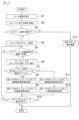
- FIG. 5 is an example of a flowchart showing the procedure of information processing according to this embodiment. Each process in the flowchart of FIG. 5 is executed by the controller 11.
- step S1 the controller 11 acquires information regarding the home screen from the storage device 2, and outputs a control command for displaying the home screen to the display 1.
- the display 1 displays a home screen based on control commands (including image data) input from the controller 11.
- the home screen is composed of a widget display area WA in which widgets W1 to W4 are displayed, and a fixed display area PA provided around the widget display area WA.
- the controller 11 outputs a control command to the display 1 to display the fixed display area PA at the upper and lower ends and the left and right ends of the screen display D.
- Widgets W1 to W4 are arranged in the main layer L1, as in the example of FIG. 3(A).
- step S2 the controller 11 detects a touch operation on the screen display of the display 1.
- the controller 11 determines the type of touch operation based on information input from the display 1.
- step S3 the controller 11 determines whether the operation on the screen display is a scroll operation based on the processing result in step S2. If the controller 11 makes a positive determination, the process proceeds to step S4, and if the controller 11 makes a negative determination, the process proceeds to step S13.
- step S13 the controller 11 executes display control on the display according to the operation on the screen display based on the processing result in step S2. For example, if the operation on the display 1 is a tap operation and the tapped object is a widget, the controller 11 outputs a control command to the display 1 to display the screen of the application corresponding to the tapped widget. do.
- step S13 ends, the controller 11 ends the process in the flowchart shown in FIG.
- step S4 the controller 11 executes a scrolling process to scroll the main layer of the screen display based on the processing result in step S2. For example, the controller 11 identifies the scroll direction based on the scroll operation direction in the scroll operation. Further, for example, the controller 11 specifies the scroll operation speed based on the operation speed in the scroll operation. The controller 11 outputs to the display 1 a control command for scrolling the main layer in a direction corresponding to the scroll operation direction as a scroll process. Further, the controller 11 outputs a control command to the display 1 to increase the scroll display speed of the widget as the scroll operation speed becomes faster. Further, the controller 11 outputs a control command to the display 1 for scrolling the icon section later than the panel section as a scrolling process. Through the process in step S4, the display 1 displays a screen in which the entire main layer including widgets scrolls in the scroll direction.
- step S5 the controller 11 determines whether the widget placed in the main layer has been scrolled by the scrolling process in step S4 and has reached the end of the screen display on the display. In this embodiment, the controller 11 determines whether the panel unit has reached the boundary between the widget display area (main layer) and the fixed display area. If a positive determination is made by the controller 11, the process proceeds to step S6, and if a negative determination is made, the process waits in step S5 until a positive determination is made.
- step S6 the controller 11 executes a migration process to migrate the widget determined to have reached the end of the screen display in step S5 from the main layer to the sub layer.
- the controller 11 outputs to the display 1 a control command for changing the affiliation of the widget that has reached the end of the screen display from the main layer to the sub layer.
- the controller 11 outputs a control command to the display 1 to display the widget that has been transitioned to the sub layer while maintaining the relationship between the scroll display of the panel section and the scroll display of the icon section in the main layer.
- the controller 11 outputs to the display 1 a control command for displaying the widget that has transitioned to the sub layer inside the edge of the screen display.
- step S7 the controller 11 determines whether a widget is placed in the sub layer before step S6. For example, before executing the migration process in step S6, the controller 11 determines whether there is a widget belonging to the sub layer. If the controller 11 determines that there is no widget belonging to the sub layer, that is, if the transition process in step S6 is the first transition process in the flowchart shown in FIG. 5, the process advances to step S8. On the other hand, if the controller 11 determines that there is one or more widgets belonging to the sub layer, that is, if the transition process in step S6 is the second or subsequent transition process in the flowchart shown in FIG. Proceed to.
- step S8 the controller 11 executes a transparency change process for changing the transparency of the widget that has been transferred from the main layer to the sub layer by the process in step S6 compared to before the widget was transferred to the sub layer. .
- the controller 11 outputs a control command to the display 1 to make the transparency of the widget that has been transferred to the sub layer higher than that before the widget has been transferred to the sub layer.
- step S9 the controller 11 executes a size change process for the widget that has been transferred from the main layer to the sub layer by the process in step S6, to change the size of the widget compared to before the widget was transferred to the sub layer.
- the controller 11 outputs a control command to the display 1 to make the size of the widget that has been transferred to the sub layer smaller than that before the widget has been transferred to the sub layer.
- step S10 the controller 11 determines whether scrolling display of the main layer has been completed through the scrolling process in step S4. For example, the controller 11 determines whether the end of the main layer located in the opposite direction to the scroll direction has reached the end of the screen display. The controller 11 determines that scrolling display of the main layer is completed when the end of the main layer reaches the end of the screen display. On the other hand, if the end of the main layer has not reached the end of the screen display, the controller 11 determines that the scroll display of the main layer has not been completed. Further, for example, the controller 11 may determine whether there is a widget belonging to the main layer. In this case, if there is no widget belonging to the main layer, the controller 11 determines that scrolling display of the main layer has been completed.
- the controller 11 determines that the scroll display of the main layer is not completed. If the controller 11 makes a positive determination, the controller 11 ends the process in the flowchart shown in FIG. On the other hand, if the controller 11 makes a negative determination, the process returns to step S5, and the processes from step S5 to step S12 are repeatedly executed until a positive determination is made in step S10.
- step S11 the controller 11 executes a transparency change process for changing the transparency of the widget that has been transferred from the main layer to the sub layer by the process in step S6 compared to before the widget was transferred to the sub layer. .
- This transparency change process by the controller 11 corresponds to the process in step S8.
- step S11 the controller 11 executes a transparency change process that is different from the process in step S8.
- step S6 the controller 11 executes a transparency change process on the widgets arranged in the sub layer to change the transparency of the widgets compared to before the process in step S6 is executed.
- the controller 11 issues a control command to the display 1 before step S6 to make the transparency of the widgets arranged in the sub layer higher than before the process in step S6 is executed. Output.
- step S12 the controller 11 executes a size change process for the widget that has been transferred from the main layer to the sub layer by the process in step S6, to change the size of the widget compared to before the widget was transferred to the sub layer.
- This dimension change process by the controller 11 corresponds to the process in step S9.
- step S12 the controller 11 executes a dimension change process different from the process in step S9.
- the controller 11 executes a size change process on the widget placed in the sub layer before step S6 to change the size of the widget compared to before the process in step S6 is performed.
- the controller 11 outputs a control command to the display 1 to make the dimensions of the widgets arranged in the sub layer before step S6 smaller than before the process in step S6 is executed. .
- step S12 When the process in step S12 is completed, the process proceeds to step S10, and as described above, the controller 11 determines whether scroll display of the main layer has been completed by the scroll process in step S4.
- the information processing device according to the comparative example unlike the information processing device 10 according to the present embodiment, does not have functions equivalent to the widget display position detection section 14, the widget migration section 15, and the sub-layer display control section 16. However, other functions are assumed to be similar to those of the information processing device 10 according to the present embodiment.
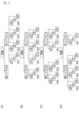
- FIG. 6 is a diagram showing how the screen changes by the information processing device according to the comparative example when a scroll operation is performed.
- the panel portion p4 of the widget W4 reaches the boundary between the widget display area WA and the fixed display area PA (FIG. 6(B)).
- the information processing apparatus according to the comparative example does not perform any processing on the widget W4 that has reached the end of the screen display. Therefore, the display 1 displays a screen in which the panel p section 4 of the widget W4 is missing from the edge of the screen display (FIG. 6(C)).
- the display 1 displays a screen in which widget W4, widget W3, and widget W2 are cut off from the edge of the screen in this order (FIG. 6(D)). If the widget is displayed so as to disappear from the edge of the screen display after the scroll operation, a problem arises in that the driver or passenger in the passenger seat feels uncomfortable with the widget display.
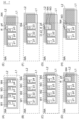
- FIG. 7 is a diagram showing how the screen changes by the information processing device 10 according to the present embodiment when a scroll operation is performed.
- FIG. 8 is a diagram showing a continuation of the screen transition shown in FIG. 7.
- FIG. 9 is a diagram for explaining the processing of the information processing device 10 according to this embodiment.
- the information processing device 10 When a predetermined period of time has elapsed since the main layer L1 scrolled from left to right, the panel portion p4 of the widget W4 reaches the boundary between the widget display area WA and the fixed display area (FIG. 7(C)).
- the information processing device 10 outputs a control command to the display 1 to change the affiliation of the widget W4 from the main layer L1 to the sub layer L2, as shown in FIG. 9(B).
- the information processing device 10 also sends a control command to display the widget W4 that has been moved to the sub layer L2 while maintaining the relationship between the scroll display of the panel part p4 and the scroll display of the icon part i4 in the main layer L1. Output to 1.
- the information processing device 10 outputs a control command to the display 1 to make the transparency of the widget W4 that has been transferred to the sub layer L2 higher than that before the widget W4 has been transferred to the sub layer L2. Furthermore, the information processing device 10 outputs a control command to the display 1 to make the size of the widget W4 that has been transferred to the sub layer L2 smaller than that before the widget W4 has been transferred to the sub layer L2. Furthermore, the information processing device 10 outputs to the display 1 a control command for displaying the widget W4 that has moved to the sub layer L2 inside the edge of the screen display. As a result, the display 1 displays the widget W4 shown in FIG. 7(C) in a transparent and small size, and also displays the widget W4 located on the back side on the screen (FIG. 7(D)).
- the information processing device 10 outputs a control command to the display 1 to change the affiliation of the widget W3 from the main layer L1 to the sub layer L2, as shown in FIG. 9(C). Furthermore, the information processing device 10 sends a control command to display the widget W3 that has moved to the sub layer L2 while maintaining the relationship between the scroll display of the panel part p3 and the scroll display of the icon part i3 in the main layer L1. Output to 1.
- the information processing device 10 also outputs a control command to the display 1 to make the transparency of the widget W4 higher than before the widget W3 moves to the sub layer L2.
- the information processing device 10 also sends a control command to the display 1 to make the transparency of the widget W3 that has been transferred to the sub layer L2 higher than before the transfer to the sub layer L2, and lower than the transparency of the widget W4. Output to.
- the widget W4 on the sub layer L2 is displayed more transparently than before the widget W3 was transferred to the sub layer L2 (FIG. 7(G)).
- the widget W3 on the sublayer L2 is displayed more transparently than before moving to the sublayer L2.
- the transparency of the widget W4 is higher than that of the widget W3, and the widget W4 is displayed more transparently than the widget W3 (FIG. 7(G)).
- the information processing device 10 outputs a control command to the display 1 to make the size of the widget W4 smaller than before the widget W3 moves to the sub layer L2.
- the information processing device 10 also outputs a control command to the display 1 to make the size of the widget W3 that has been transferred to the sublayer L2 smaller than before the widget W3 was transferred to the sublayer, and larger than the size of the widget W4.
- the widget W4 on the sub layer L2 is displayed smaller than before the widget W3 was transferred to the sub layer L2 (FIG. 7(G)).
- the widget W3 on the sub layer L2 is displayed smaller than before moving to the sub layer L2.
- the dimensions of the widget W4 are smaller than the dimensions of the widget W3, and the widget W4 is displayed smaller than the widget W3 (FIG. 7(G)).
- the information processing device 10 also provides visual control instructions for widgets W3 and W4 on the sub layer L2, such as widgets W4 and W3 being displayed in the order from the back of the screen to the front of the screen.
- a control command for adjusting the arrangement is output to the display 1.
- the widget W4 is displayed on the sub layer L2 as if it were located further back on the screen than the widget W3 (FIG. 7(G)).
- the information processing device 10 repeatedly executes the process of changing the widget's belonging location, and the process of changing the transparency and changing the size of the widget that has been transferred to the sub layer.
- the display 1 displays the screens shown in each drawing in the order of FIGS. 7(E) to 7(H) and FIGS. 8(A) to 8(D) as time passes.
- the screen display of the display 1 includes a main layer located in the front and a sub layer located behind the main layer.
- the controller 11 detects an operation on the screen display, and when the operation on the screen display is a scroll operation, executes a scroll process to scroll the main layer, and scrolls the widgets arranged in the main layer by the scroll process to change the screen display.
- a migration process is executed to migrate the widget that has reached the end from the main layer to the sub layer.
- the widget can be displayed on the sublayer behind the main layer, so even if the main layer scrolls, the widget remains at the edge of the screen display. This can prevent the image from appearing as if it is missing.
- the screen display scrolls the user's discomfort with the widget display can be suppressed.
- the controller 11 executes a transparency change process that increases the transparency of the widget that has been transferred to the sub layer compared to before the widget has been transferred to the sub layer.
- the widget that has moved to the sub layer is displayed more transparently than before moving to the sub layer, so that it is possible to visually express that the widget has moved to the rear of the screen.
- the driver or front passenger can easily grasp the context of the widget on the main layer.
- the controller 11 executes a size change process to change the dimensions of the widget that has been transferred to the sub layer compared to before the widget has been transferred to the sub layer.
- the dimensions of the widget that has moved to the sub layer are changed so that they are transparent compared to before moving to the sub layer, so it is possible to visually express that the widget has moved from the main layer located in the front.
- the size change process includes a process of reducing the size of the widget that has been transferred to the sub layer compared to before the widget has been transferred to the sub layer.
- the screen display of the display 1 includes a fixed display area that is independent of scrolling operations, in addition to the widget display area in which widgets are displayed.
- the display 1 has a shape that is longer in the horizontal direction than in the vertical direction.
- the controller 11 displays the fixed display area PA at the upper and lower ends and the left and right ends of the screen display. Thereby, a screen display like the example shown in FIG. 2(B) can be realized.
- the controller 11 sets the boundary between the widget display area and the fixed display area as the edge of the screen display, so that the widget that has migrated to the sub layer is displayed inside the edge of the screen display. , place widgets on the sublayer. Thereby, it is possible to prevent the fixed display area from being displayed superimposed on the widget that has moved to the sub layer, and it is possible to display the widget on the sub layer. As a result, when the screen display scrolls, the user's discomfort with the widget display can be suppressed.
- the migration process includes a process of changing the affiliation of an object that has reached the edge of the screen display from the main layer to the sub layer, thereby displaying it on the display 1 as a widget placed in the sub layer. . Since the migration from the main layer to the sub layer can be achieved by a relatively simple process of changing the widget's affiliation, the calculation load can be reduced.
- the object to be operated by the driver or the passenger in the front passenger seat is a widget of the application software, which includes a panel section on which information regarding the application software is displayed.
- the controller 11 performs a transition process from a main layer to a sub layer for the widget including the panel portion that has reached the end. Execute.
- the widget includes, in addition to the panel section, an icon section of the application software and a shadow section indicating the boundary between the panel section and the icon section. Even for objects such as widgets, which are composed of multiple elements, migration processing to the sub layer can be realized.
- the scrolling process includes a process of delaying the scrolling display of the icon section with respect to the scrolling display of the panel section. This can give the driver or front passenger the visual effect that the screen display is scrolling.
- the migration process includes a process of displaying the widget that has migrated to the sub layer on the display 1 while maintaining the relationship between the scroll display of the panel section and the scroll display of the icon section in the main layer.
- the positional relationship between the panel section and the icon section is maintained before and after the transition to the sub layer, so it is possible to prevent the driver or front passenger from feeling uncomfortable with the widget display due to the transition to the sub layer.
- the process of detecting a touch operation on the screen display includes the process of detecting the operation speed of the scroll operation
- the scroll process is the process of changing the scroll display speed of the widget according to the operation speed of the scroll operation. including.
- the information processing method and information processing apparatus according to the present embodiment have been described, but even if the program is for causing a computer to function as the information processing apparatus 10 according to the present embodiment, the above-mentioned implementation It has the same effect as the form.
- the information presentation device 100 was described as an example, but the present invention is not limited to this.
- the information processing method, information processing apparatus, and program according to the present invention can be applied to a device equipped with a touch panel display.
- the information processing method, information processing device, and program according to the present invention can be applied to, for example, a display, a television, etc. to which a mobile terminal such as a smartphone, a tablet terminal, a notebook computer, a personal computer, etc. can be connected.
- a widget was used as an example of an object to be operated by a driver or a passenger in a front passenger seat. It can also be applied to objects.
- a widget including a panel part, an icon part, and a shadow part was described as an example, but a widget includes at least one of the panel part, an icon part, and a shadow part.
- the configuration may include the following.
- the left-right direction was exemplified as the scroll direction of the scroll operation, but the scroll direction may be the up-down direction.
- the display 1 is described as having a shape that is longer in the horizontal direction than in the up-down direction, but the display 1 may have a shape that is longer in the up-down direction than in the left-right direction.
- the display 1 may have a shape other than a rectangle.
- the screen display in which the fixed display area is provided around the widget display area has been described as an example, but the fixed display area is a display that is longer in the vertical direction than in the horizontal direction. In this case, it may be displayed at the left end and right end of the screen display, or at one of the left end and right end.
Landscapes
- Engineering & Computer Science (AREA)
- General Engineering & Computer Science (AREA)
- Theoretical Computer Science (AREA)
- Human Computer Interaction (AREA)
- Physics & Mathematics (AREA)
- General Physics & Mathematics (AREA)
- User Interface Of Digital Computer (AREA)
Priority Applications (5)
| Application Number | Priority Date | Filing Date | Title |
|---|---|---|---|
| CN202280095439.XA CN119137574A (zh) | 2022-04-28 | 2022-04-28 | 信息处理方法、信息处理装置以及程序 |
| PCT/JP2022/019368 WO2023209977A1 (ja) | 2022-04-28 | 2022-04-28 | 情報処理方法、情報処理装置、及びプログラム |
| EP22938745.1A EP4517499A4 (en) | 2022-04-28 | 2022-04-28 | Information processing method, information processing device, and program |
| US18/860,305 US20250298503A1 (en) | 2022-04-28 | 2022-04-28 | Information processing method, information processing device, and program |
| JP2024517784A JP7823735B2 (ja) | 2022-04-28 | 2022-04-28 | 情報処理方法、情報処理装置、及びプログラム |
Applications Claiming Priority (1)
| Application Number | Priority Date | Filing Date | Title |
|---|---|---|---|
| PCT/JP2022/019368 WO2023209977A1 (ja) | 2022-04-28 | 2022-04-28 | 情報処理方法、情報処理装置、及びプログラム |
Publications (1)
| Publication Number | Publication Date |
|---|---|
| WO2023209977A1 true WO2023209977A1 (ja) | 2023-11-02 |
Family
ID=88518165
Family Applications (1)
| Application Number | Title | Priority Date | Filing Date |
|---|---|---|---|
| PCT/JP2022/019368 Ceased WO2023209977A1 (ja) | 2022-04-28 | 2022-04-28 | 情報処理方法、情報処理装置、及びプログラム |
Country Status (5)
| Country | Link |
|---|---|
| US (1) | US20250298503A1 (https=) |
| EP (1) | EP4517499A4 (https=) |
| JP (1) | JP7823735B2 (https=) |
| CN (1) | CN119137574A (https=) |
| WO (1) | WO2023209977A1 (https=) |
Citations (5)
| Publication number | Priority date | Publication date | Assignee | Title |
|---|---|---|---|---|
| JP2003330586A (ja) * | 2002-05-13 | 2003-11-21 | Mobile Computing Technologies:Kk | 表示制御装置、携帯型情報端末装置、表示制御情報、及び表示制御方法 |
| JP2012079065A (ja) * | 2010-09-30 | 2012-04-19 | Toshiba Corp | 電子機器、アイコンの表示方法、電子機器のプログラム |
| JP2013235394A (ja) * | 2012-05-08 | 2013-11-21 | Softbank Mobile Corp | 情報端末装置 |
| JP2014074979A (ja) * | 2012-10-03 | 2014-04-24 | Konica Minolta Inc | 表示装置、画像形成装置、および表示制御プログラム |
| JP2014194773A (ja) | 2013-03-28 | 2014-10-09 | Samsung Electronics Co Ltd | ディスプレイ装置のディスプレイ方法及びディスプレイ装置 |
Family Cites Families (10)
| Publication number | Priority date | Publication date | Assignee | Title |
|---|---|---|---|---|
| US20050044509A1 (en) * | 2003-05-07 | 2005-02-24 | Hunleth Frank A. | Item selection using helical menus |
| JP5203655B2 (ja) | 2007-09-07 | 2013-06-05 | キヤノン株式会社 | コンテンツ表示装置及びその表示方法 |
| JP5086960B2 (ja) | 2008-09-26 | 2012-11-28 | キヤノン株式会社 | データ閲覧装置及びデータ閲覧装置の制御方法 |
| JP2010108171A (ja) | 2008-10-29 | 2010-05-13 | Canon Inc | コンテンツ閲覧装置及びその制御方法 |
| KR101558207B1 (ko) * | 2009-09-14 | 2015-10-07 | 엘지전자 주식회사 | 이동 단말기 및 이동 단말기의 아이템 설정 방법 |
| KR101762612B1 (ko) | 2010-12-07 | 2017-07-31 | 삼성전자 주식회사 | 목록 표시 방법 및 장치 |
| JP2012247861A (ja) | 2011-05-25 | 2012-12-13 | Panasonic Corp | タッチスクリーン装置、タッチ操作入力方法及びプログラム |
| JP5749681B2 (ja) | 2012-05-08 | 2015-07-15 | ソフトバンクモバイル株式会社 | 情報端末装置 |
| DE102013000880A1 (de) | 2013-01-10 | 2014-07-10 | Volkswagen Aktiengesellschaft | Verfahren und Vorrichtung zu Bereitstellen einer Benutzerschnittstelle in einem Fahrzeug |
| US9477381B2 (en) | 2013-03-12 | 2016-10-25 | Hexagon Technology Center Gmbh | User interface for toolbar navigation |
-
2022
- 2022-04-28 WO PCT/JP2022/019368 patent/WO2023209977A1/ja not_active Ceased
- 2022-04-28 EP EP22938745.1A patent/EP4517499A4/en not_active Withdrawn
- 2022-04-28 CN CN202280095439.XA patent/CN119137574A/zh active Pending
- 2022-04-28 US US18/860,305 patent/US20250298503A1/en active Pending
- 2022-04-28 JP JP2024517784A patent/JP7823735B2/ja active Active
Patent Citations (5)
| Publication number | Priority date | Publication date | Assignee | Title |
|---|---|---|---|---|
| JP2003330586A (ja) * | 2002-05-13 | 2003-11-21 | Mobile Computing Technologies:Kk | 表示制御装置、携帯型情報端末装置、表示制御情報、及び表示制御方法 |
| JP2012079065A (ja) * | 2010-09-30 | 2012-04-19 | Toshiba Corp | 電子機器、アイコンの表示方法、電子機器のプログラム |
| JP2013235394A (ja) * | 2012-05-08 | 2013-11-21 | Softbank Mobile Corp | 情報端末装置 |
| JP2014074979A (ja) * | 2012-10-03 | 2014-04-24 | Konica Minolta Inc | 表示装置、画像形成装置、および表示制御プログラム |
| JP2014194773A (ja) | 2013-03-28 | 2014-10-09 | Samsung Electronics Co Ltd | ディスプレイ装置のディスプレイ方法及びディスプレイ装置 |
Non-Patent Citations (1)
| Title |
|---|
| See also references of EP4517499A4 |
Also Published As
| Publication number | Publication date |
|---|---|
| EP4517499A4 (en) | 2025-06-04 |
| EP4517499A1 (en) | 2025-03-05 |
| CN119137574A (zh) | 2024-12-13 |
| JP7823735B2 (ja) | 2026-03-04 |
| JPWO2023209977A1 (https=) | 2023-11-02 |
| US20250298503A1 (en) | 2025-09-25 |
Similar Documents
| Publication | Publication Date | Title |
|---|---|---|
| TWI514234B (zh) | 用於手勢識別之方法及裝置 | |
| JP5876363B2 (ja) | 制御装置及びプログラム | |
| US20110296329A1 (en) | Electronic apparatus and display control method | |
| US9280265B2 (en) | Input control device, input control method, and input control program for controlling display target upon receiving input on display screen of display device | |
| EP2703986A2 (en) | User terminal apparatus and controlling method thereof | |
| JP2013030050A (ja) | スクリーンパッドによる入力が可能なユーザインタフェース装置、入力処理方法及びプログラム | |
| JP6313395B1 (ja) | 描画処理方法、描画処理プログラム及び描画処理装置 | |
| KR20110089448A (ko) | 가볍게 튀기는 스크롤링 | |
| US8762840B1 (en) | Elastic canvas visual effects in user interface | |
| KR20150095540A (ko) | 사용자 단말 장치 및 이의 디스플레이 방법 | |
| WO2012160829A1 (ja) | タッチスクリーン装置、タッチ操作入力方法及びプログラム | |
| WO2015010846A1 (en) | Methods for modifying images and related aspects | |
| CN107704184A (zh) | 用于操作装置的方法和操作设备 | |
| US9632697B2 (en) | Information processing apparatus and control method thereof, and non-transitory computer-readable medium | |
| CN109923508B (zh) | 用于运行操作系统的方法和操作系统 | |
| CN103853490A (zh) | 车用触控显示装置及应用于其上的显示方法 | |
| CN108089643B (zh) | 电子设备和增强与电子设备交互的方法 | |
| JP7823735B2 (ja) | 情報処理方法、情報処理装置、及びプログラム | |
| US20180232115A1 (en) | In-vehicle input device and in-vehicle input device control method | |
| JP2007156991A (ja) | 車載用表示装置 | |
| JP2012212318A (ja) | ナビゲーション装置 | |
| JP7838390B2 (ja) | 情報処理方法、情報処理装置、及びプログラム | |
| JP2024126499A (ja) | 情報処理方法及び情報処理装置 | |
| JP7517604B2 (ja) | 表示制御装置及び表示制御方法 | |
| JP7844190B2 (ja) | 情報処理装置、及び情報処理方法 |
Legal Events
| Date | Code | Title | Description |
|---|---|---|---|
| 121 | Ep: the epo has been informed by wipo that ep was designated in this application |
Ref document number: 22938745 Country of ref document: EP Kind code of ref document: A1 |
|
| WWE | Wipo information: entry into national phase |
Ref document number: 2024517784 Country of ref document: JP |
|
| WWE | Wipo information: entry into national phase |
Ref document number: 18860305 Country of ref document: US |
|
| WWE | Wipo information: entry into national phase |
Ref document number: 202280095439.X Country of ref document: CN |
|
| WWE | Wipo information: entry into national phase |
Ref document number: 2022938745 Country of ref document: EP |
|
| NENP | Non-entry into the national phase |
Ref country code: DE |
|
| ENP | Entry into the national phase |
Ref document number: 2022938745 Country of ref document: EP Effective date: 20241128 |
|
| WWW | Wipo information: withdrawn in national office |
Ref document number: 2022938745 Country of ref document: EP |
|
| WWP | Wipo information: published in national office |
Ref document number: 18860305 Country of ref document: US |