WO2023203793A1 - 光学機器用アクチュエータおよびこれを備えたレンズ鏡筒 - Google Patents
光学機器用アクチュエータおよびこれを備えたレンズ鏡筒 Download PDFInfo
- Publication number
- WO2023203793A1 WO2023203793A1 PCT/JP2022/040141 JP2022040141W WO2023203793A1 WO 2023203793 A1 WO2023203793 A1 WO 2023203793A1 JP 2022040141 W JP2022040141 W JP 2022040141W WO 2023203793 A1 WO2023203793 A1 WO 2023203793A1
- Authority
- WO
- WIPO (PCT)
- Prior art keywords
- weight
- actuator
- vibration
- guide shaft
- equipment according
- Prior art date
- Legal status (The legal status is an assumption and is not a legal conclusion. Google has not performed a legal analysis and makes no representation as to the accuracy of the status listed.)
- Ceased
Links
Images


Classifications
-
- H—ELECTRICITY
- H02—GENERATION; CONVERSION OR DISTRIBUTION OF ELECTRIC POWER
- H02N—ELECTRIC MACHINES NOT OTHERWISE PROVIDED FOR
- H02N2/00—Electric machines in general using piezoelectric effect, electrostriction or magnetostriction
- H02N2/02—Electric machines in general using piezoelectric effect, electrostriction or magnetostriction producing linear motion, e.g. actuators; Linear positioners ; Linear motors
- H02N2/021—Electric machines in general using piezoelectric effect, electrostriction or magnetostriction producing linear motion, e.g. actuators; Linear positioners ; Linear motors using intermittent driving, e.g. step motors, piezoleg motors
- H02N2/025—Inertial sliding motors
-
- G—PHYSICS
- G02—OPTICS
- G02B—OPTICAL ELEMENTS, SYSTEMS OR APPARATUS
- G02B26/00—Optical devices or arrangements for the control of light using movable or deformable optical elements
- G02B26/08—Optical devices or arrangements for the control of light using movable or deformable optical elements for controlling the direction of light
- G02B26/0816—Optical devices or arrangements for the control of light using movable or deformable optical elements for controlling the direction of light by means of one or more reflecting elements
- G02B26/0833—Optical devices or arrangements for the control of light using movable or deformable optical elements for controlling the direction of light by means of one or more reflecting elements the reflecting element being a micromechanical device, e.g. a MEMS mirror, DMD
- G02B26/0858—Optical devices or arrangements for the control of light using movable or deformable optical elements for controlling the direction of light by means of one or more reflecting elements the reflecting element being a micromechanical device, e.g. a MEMS mirror, DMD the reflecting means being moved or deformed by piezoelectric means
-
- G—PHYSICS
- G02—OPTICS
- G02B—OPTICAL ELEMENTS, SYSTEMS OR APPARATUS
- G02B27/00—Optical systems or apparatus not provided for by any of the groups G02B1/00 - G02B26/00, G02B30/00
- G02B27/64—Imaging systems using optical elements for stabilisation of the lateral and angular position of the image
- G02B27/646—Imaging systems using optical elements for stabilisation of the lateral and angular position of the image compensating for small deviations, e.g. due to vibration or shake
-
- G—PHYSICS
- G02—OPTICS
- G02B—OPTICAL ELEMENTS, SYSTEMS OR APPARATUS
- G02B7/00—Mountings, adjusting means, or light-tight connections, for optical elements
- G02B7/02—Mountings, adjusting means, or light-tight connections, for optical elements for lenses
-
- G—PHYSICS
- G02—OPTICS
- G02B—OPTICAL ELEMENTS, SYSTEMS OR APPARATUS
- G02B7/00—Mountings, adjusting means, or light-tight connections, for optical elements
- G02B7/02—Mountings, adjusting means, or light-tight connections, for optical elements for lenses
- G02B7/04—Mountings, adjusting means, or light-tight connections, for optical elements for lenses with mechanism for focusing or varying magnification
- G02B7/08—Mountings, adjusting means, or light-tight connections, for optical elements for lenses with mechanism for focusing or varying magnification adapted to co-operate with a remote control mechanism
-
- H—ELECTRICITY
- H02—GENERATION; CONVERSION OR DISTRIBUTION OF ELECTRIC POWER
- H02N—ELECTRIC MACHINES NOT OTHERWISE PROVIDED FOR
- H02N2/00—Electric machines in general using piezoelectric effect, electrostriction or magnetostriction
- H02N2/02—Electric machines in general using piezoelectric effect, electrostriction or magnetostriction producing linear motion, e.g. actuators; Linear positioners ; Linear motors
- H02N2/06—Drive circuits; Control arrangements or methods
- H02N2/062—Small signal circuits; Means for controlling position or derived quantities, e.g. for removing hysteresis
Definitions
- the present disclosure relates to an actuator for an optical device that drives an optical device such as a lens back and forth along an optical axis direction, and a lens barrel equipped with the actuator.
- Patent Document 1 discloses a drive shaft, a piezoelectric element fixed at a first end of the drive shaft using an adhesive or the like, and a piezoelectric element whose second end is movable in parallel to the axial direction.
- a driving device including a spring (spring, etc.) is disclosed.
- the configuration of the conventional drive device described above has the following problems. That is, in the configuration of the drive device disclosed in the above-mentioned publication, even if the drive shaft or the like receives an external force in a direction different from the axial direction, the influence of the external force can be alleviated by the external force mitigation support portion such as a spring.
- An object of the present disclosure is to provide an actuator for an optical device that can effectively prevent failure of a piezoelectric element due to resonance while ensuring high response characteristics, and a lens barrel equipped with the actuator.
- An actuator for optical equipment includes a movable frame including a lens, a guide shaft, a vibration applying section, a first weight, a first elastic element, a second weight, a first frame, and an elastic member. It is equipped with.
- the guide shaft supports the movable frame so as to be movable along the optical axis of the lens.
- the vibration applying section applies vibration to the first end side of the guide shaft.
- the first weight is fixed to the vibration applying section along the axial direction of the guide shaft.
- the first elastic element is fixed along the axial direction of the guide shaft to the end of the first weight opposite to the vibration applying part, and has elasticity.
- the second weight is fixed to the first weight along the axial direction of the guide shaft via the first elastic element.
- the first frame supports a vibration applying section, a first weight, a first elastic element, and a second weight, which are arranged on the first end side of the guide shaft.
- the elastic member is provided on the first end side of the guide shaft, and axially moves the vibration applying section to the first end of the guide shaft via the first weight first elastic element and the second weight. and press.
- FIG. 1 is a perspective view showing the configuration of a lens barrel including an actuator for optical equipment according to an embodiment of the present disclosure.
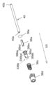
- 2 is an exploded view of each component that constitutes the lens barrel of FIG. 1.
- FIG. 3 is an exploded view of each component that constitutes the third and fourth group units included in the lens barrel of FIG. 2.
- FIG. 4 is a side view showing the direction of vibration applied by the piezoelectric element in the third and fourth group units of FIG. 3;
- FIG. 4 is a front view of the third and fourth group units in FIG. 3 viewed from the image sensor side.
- FIG. 3 is a view of the fixed frame included in the lens barrel of FIG. 2 as viewed from the image plane side.
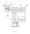
- FIG. 7 is a sectional view taken along line LL in FIG. 7.
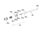
- FIG. 3 is an exploded perspective view showing the configuration around the connecting portion between the piezoelectric element and the main shaft guide.
- FIG. 3 is a cross-sectional view schematically showing the configuration around the piezoelectric element and the configuration of the press-fitted portion on the second end side of the main shaft guide.
- FIG. 7 is an enlarged view showing a portion where the main shaft guide is press-fitted into the guide holding frame.
- FIG. 11 is a diagram showing the equivalent vibration model of FIG. 10. The figure which shows the equivalent vibration model used as a comparative example of FIG. 12A. A graph showing the results of comparing the frequency response characteristics of the guide shaft and weight.
- FIG. 12A and 12B are graphs showing the results of comparing the frequency response characteristics of the simplified vibration applying mechanisms of FIG. 12B.
- FIG. 3 is a perspective view illustrating focus control of the third and fourth group units.
- FIG. 7 is an exploded perspective view showing a configuration around a connecting portion between a piezoelectric element and a main shaft guide included in an actuator for optical equipment according to another embodiment of the present disclosure.
- 17 is a diagram showing an equivalent vibration model of the actuator for optical equipment shown in FIG. 16.
- FIG. 17 is a graph showing experimental results comparing the configuration of FIG. 16 and the configuration of a comparative example. This is an enlarged graph of the band actually used in the graph of FIG. 18.
- FIG. 7 is an exploded perspective view showing a configuration including a three-stage weight unit included in an actuator for optical equipment according to still another embodiment of the present disclosure.
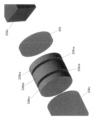
- FIG. 21 is an exploded perspective view showing a simulation model of the weight unit shown in FIG. 20, showing a configuration in which the weight unit model shown in FIG. 21 as a comparative example is divided into three (three stages); 23 is an enlarged view of the divided first to third weight unit models included in FIG. 22.
- FIG. 21 is a graph showing the responsiveness of the simulation model of this embodiment shown in FIG. 20.
- FIG. 24B is an enlarged view of part A in FIG. 24A.
- the lens barrel 10 equipped with an actuator for optical equipment according to an embodiment of the present disclosure will be described below using FIGS. 1 to 15.
- the lens barrel 10 includes an optical system including a plurality of lenses, a first group unit 11, a second group unit 12, and a cam frame 13. , a third group/fourth group unit 14 , a fifth group unit 16 , an exterior unit 17 , and a base ring 18 .
- the lens barrel 10 is attached to a mount portion of a camera body (not shown) at the base ring 18.
- the optical axis AX direction shown in FIG. 1 is the optical axis direction of the optical system of the lens barrel 10.
- the object side in the optical axis direction means the side opposite to the image plane side where the image sensor (not shown) of the camera body is arranged.
- the optical axis direction of the optical system of the lens barrel 10 will be referred to as the optical axis AX direction.
- (1-1) Configuration of optical system As shown in FIG. 2, the optical system of the lens barrel 10 includes a 1st group unit 11, a 2nd group unit 12, a cam frame 13, and 3rd and 4th group units 14. , a fifth group unit 16, an exterior unit 17, a base ring 18, and the like.
- the first group unit 11 is a cylindrical member, and inside thereof, a plurality of lenses are arranged on the subject side.
- the first group unit 11 moves forward and backward along the optical axis AX direction while holding a plurality of lenses on the subject side. Thereby, the distance between the plurality of lenses changes, and wide-angle photography and telephoto photography can be performed.
- the second group unit 12 is a cylindrical member arranged on the inner peripheral surface side of the first group unit 11.
- the second group unit 12 holds a plurality of lenses.
- the plurality of lenses included in the second group unit 12 are arranged closer to the image plane in the optical axis AX direction than the plurality of lenses included in the first group unit 11.
- the cam frame 13 is a cylindrical member and has a cam groove formed therein.
- the cam frame 13 is arranged on the outer peripheral surface side of the second group unit 12 and the third and fourth group units 14. Then, cam pins provided on the outer peripheral surfaces of the third and fourth group units 14 are fitted into cam grooves of the cam frame 13.
- the third and fourth group units 14 are focus units that include a focus lens L11, and similarly to the first group unit 11 and the second group unit 12, they hold a plurality of lenses.
- the third group/fourth group unit 14 is a substantially cylindrical member and holds a plurality of lenses. As shown in FIG. 2, the plurality of lenses included in the third and fourth group units 14 are arranged closer to the image plane in the optical axis AX direction than the plurality of lenses included in the second group unit 12. Furthermore, the third and fourth group units 14 hold a focus lens L11, as shown in FIG.
- the focus lens L11 is arranged on the image plane side in the optical axis AX direction among the plurality of lenses included in the third group/fourth group unit 14. Furthermore, as shown in FIG.
- the third and fourth group units 14 include a main yoke 31 and an opposing yoke 34 arranged on the outer periphery of a substantially cylindrical fixed frame 30, and a drive coil arranged on a movable frame 33. 33c.
- the third and fourth group units 14 are driven by the drive unit including the drive coil 33c, and move the movable frame 33 including the focus lens L11 in the direction of the optical axis AX while holding a plurality of lenses. Move back and forth.
- a cam pin provided to protrude from the outer circumferential surface of the third and fourth group units 14 (fixed frame 30) receives rotational driving force from a rotational driving source, and is inserted into a cam groove formed in the cam frame 13. move along.
- the fifth group unit 16 is a substantially cylindrical member disposed on the inner peripheral surface side of the first group unit 11, as shown in FIG.
- the fifth group unit 16 holds a plurality of lenses.
- the cam frame 13 is attached to the fifth group unit 16 in a relatively rotatable state.
- the exterior unit 17 is a cylindrical member that constitutes the exterior portion of the lens barrel 10, as shown in FIG. An annular focus ring, a zoom ring, etc. are rotatably attached to the outer peripheral surface of the exterior unit 17.
- the base ring 18 is attached to the end of the exterior unit 17 on the image plane side, and together with the exterior unit 17 constitutes the exterior portion of the lens barrel 10 .
- the base ring 18 is then attached to the camera body (not shown).
- (1-2) Configuration of the 3rd and 4th group units 14 The lens barrel 10 of this embodiment is a lens unit that moves the focus lens L11 held by the movable frame 33 back and forth in the optical axis AX direction.
- the third and fourth group units 14 constituting the lens barrel 10 include a fixed frame 30, a main yoke 31, a magnet (driver) 32 (see FIG.
- a movable It includes a frame 33, a main shaft guide (guide shaft) 40, a sub-shaft guide 41, an opposing yoke 34, a guide holding frame (second frame body) 35, and a vibration applying mechanism (vibration applying section) 36.
- FIGS. 3 to 8 show the configuration of the third and fourth group units 14. 6 is a sectional view taken along line JJ in FIG. 5, and FIG. 8 is a sectional view taken along line LL in FIG.
- the fixed frame 30 is a substantially cylindrical member that forms the outer shell of the third and fourth group units 14, and includes a main yoke 31, a magnet 32, a movable frame 33, a main shaft guide (guide shaft) 40, a sub-shaft guide 41, etc. is placed. A part of the fixed frame 30 is used as a first frame that constitutes an actuator for an optical device, which will be described later.
- the main yoke 31 is a substantially U-shaped member when viewed from the side, and as shown in FIG. 5, two main yokes 31 are provided on the outer peripheral surface side of the fixed frame 30. .
- the magnet 32 is provided between the approximately U-shaped portions of the main yoke 31, and constitutes an actuator that drives the movable frame 33 together with a drive coil 33c, which will be described later. Then, the magnet 32 generates a magnetic field M in the Z direction (inward in the radial direction) shown by the arrow in FIG. More specifically, the magnet 32 placed on the upper side shown in FIG. 6 generates a magnetic field M downward in the figure, and the magnet 32 placed on the lower side generates a magnetic field M upward in the figure.
- the movable frame 33 is movable back and forth in the direction of the optical axis AX relative to the fixed frame 30, and includes a main shaft bearing part 33a, a sub-shaft bearing part 33b, and a drive coil. 33c, and a main body portion 33d.
- the main shaft bearing part 33a is a through hole formed in the main body part 33d along the optical axis AX direction, into which the main shaft guide 40 is inserted.
- the subshaft bearing part 33b is a through hole formed in the main body part 33d along the optical axis AX direction, into which the subshaft guide 41 is inserted.
- the main shaft guide 40 is slidably engaged with the main shaft bearing part 33a, and serves as a guide member when moving the movable frame 33 relative to the fixed frame 30, as shown in FIGS. 3 and 4. It is arranged along the axis AX direction.
- a first end 40a of the main shaft guide 40 in the direction of the optical axis AX is connected to a vibration imparting mechanism 36 (piezoelectric element 36a) to be described later (see FIGS. 8 and 9).
- a second end 40b opposite to the first end 40a is supported in a fixed state in a press-fit hole 35a (see FIGS. 10 and 11) formed in the guide holding frame 35. Further, as shown in FIG. 4, when the movable frame 33 is moved, the main shaft guide 40 is applied with a predetermined vibration in the vibration applying direction in the figure from a vibration applying mechanism 36, which will be described later.
- the first end 40a of the main shaft guide 40 is inserted into an insertion hole 30a formed in the fixed frame 30, as shown in FIG.
- An annular gap d is formed between the inner peripheral surface of the insertion hole 30a and the outer peripheral surface of the main shaft guide 40.
- the annular gap d is formed so as to surround the outer peripheral surface of the main shaft guide 40.
- the countershaft guide 41 is inserted through the countershaft bearing portion 33b, and is arranged substantially parallel to the main shaft guide 40, as shown in FIGS. 3 and 4.
- One end of the sub-shaft guide 41 in the optical axis AX direction is held by the fixed frame 30, and the opposite end thereof is held by a guide holding frame 35, which will be described later.
- the secondary shaft guide 41 serves as a guide for the movable frame 33 so that the posture of the movable frame 33 can be maintained together with the main shaft guide 40 when the movable frame 33 moves back and forth in the optical axis AX direction along the main shaft guide 40. Functions as a member.
- the drive coil 33c is fixed to the main body 33d side of the movable frame 33, and is arranged near the main yoke 31 and the magnet 32 fixed to the fixed frame 30 side.
- a current flows through the drive coil 33c in the X-axis direction perpendicular to the drawing, as shown in FIG.
- a Lorentz force F1 is applied to the movable frame 33 in the Y-axis direction (to the left) by the radially inward magnetic field generated by the magnet 32 and the current flowing through the drive coil 33c. can be generated. Therefore, when current flows through the drive coil 33c, the movable frame 33 moves back and forth in the optical axis AX direction.
- the thrust force applied to the movable frame 33 depends on the Lorentz force F1 generated by the magnet 32 and the drive coil 33c. That is, in this embodiment, the thrust of the movable frame 33 does not depend on the vibration applied from the vibration applying mechanism 36, which will be described later.
- the main body portion 33d holds a focus lens L11 in the center portion.
- a main shaft guide 40 and a sub-shaft guide 41 are inserted through the main shaft bearing part 33a and the sub-shaft bearing part 33b, which are provided on the outer peripheral side of the portion of the main body part 33d that holds the focus lens L11.
- the opposing yoke 34 is attached to cover the opening of the approximately U-shaped main yoke 31.
- the guide holding frame 35 is arranged on the image plane side of the movable frame 33 in the direction of the optical axis AX, which is opposite to the subject side.
- the guide holding frame 35 holds each end of the main shaft guide 40 (second end 40b side) and the sub-shaft guide 41 at a position on the image plane side of the movable frame 33.
- the guide holding frame 35 also has a press-fit hole 35a into which the second end 40b of the main shaft guide 40 is press-fitted, and a groove 35b formed concentrically with the press-fit hole 35a on the outer circumferential side of the press-fit hole 35a.
- the position detecting section 52 includes a sensor magnet 53 fixed to the movable frame 33 and an MR element (not shown) fixed to the fixed frame 30 so as to face the sensor magnet 53.
- the position detection section 52 may be constituted by an encoder, and may be any device that can detect the position of the movable frame 33 with respect to the fixed frame 30.
- the position detection unit 52 is electrically connected to the control unit 51 and outputs the amount of movement of the sensor magnet 53 in the optical axis direction to the control unit 51.
- a coil terminal portion 55 of the drive coil 33c is electrically connected to the control section 51.
- the control unit 51 can move the movable frame 33 to a desired position by applying a drive current to the drive coil 33c based on the current position of the movable frame 33 obtained from the position detection unit 52.
- control unit 51 is also electrically connected to the vibration applying mechanism 36 and can control the operation of the vibration applying mechanism 36.
- the control unit 51 has a configuration that can freely change the amount of vibration and vibration frequency of the vibration applying mechanism 36 according to the current position and speed of the movable frame 33.
- the vibration speed of the main shaft guide shaft is higher than the moving speed of the movable frame 33.
- control unit 51 controls the vibration imparting mechanism 36 so that when the movable frame 33 moves, the spindle guide 40 moves at least twice as fast as the moving speed of the movable frame 33 within a range that does not exceed the limit of mechanical strength. control to vibrate at a speed of
- the vibration imparting mechanism 36 applies vibration to the main shaft guide 40 along a direction substantially parallel to the axial direction of the main shaft guide 40. As shown in FIGS. 7 and 8, this mechanism is arranged at a position where the object-side end (first end 40a) of the main shaft guide 40 comes into contact. As shown in FIG. 3, the vibration applying mechanism 36 includes a piezoelectric element 36a, a weight unit 36b, a spring 36c, a holder (first frame) 36d, and a buffer sheet (buffer material) 36e.
- the vibration applying mechanism 36 is controlled to apply vibration within a range of, for example, 20 kHz to 60 kHz.
- the piezoelectric element 36a is a piezoelectric element that generates force when voltage is applied, and generates ultrasonic vibration by repeatedly expanding and contracting when an alternating current voltage is applied.
- the piezoelectric element 36a is an ultrasonic vibrator that applies a predetermined ultrasonic vibration to the spindle guide 40 in order to reduce the frictional resistance generated between the movable frame 33 (main body portion 33d) and the spindle guide 40. used as.
- the weight unit 36b is a bottomed, substantially cylindrical member, and, as shown in FIG. 9, is connected to the object-side end of the piezoelectric element 36a. Furthermore, an end of the piezoelectric element 36a on the opposite side to the connection side with the first end 40a of the spindle guide 40 is fixed to the bottom surface of the weight unit 36b with an adhesive. As shown in FIGS. 9 and 10, the weight unit 36b has a multi-stage configuration including two weights (first and second weights 36ba, 36bb), a first weight 36ba, a second weight 36bb, and a small diameter portion. 36bc and a flange portion 36bd.
- the first weight 36ba is arranged on the side where the piezoelectric element 36a is inserted and is fixed to the end of the piezoelectric element 36a.
- a flange portion 36bd is provided on the outer peripheral surface of the first weight 36ba.
- the first weight 36ba has a mass ratio of, for example, 2:1 to the second weight 36bb. That is, the first weight 36ba has about 2 ⁇ 3 of the mass of the entire weight unit 36b.
- the second weight 36bb is connected to the first weight 36ba along the axial direction of the main shaft guide 40 via the small diameter portion 36bc, and includes the bottom portion of the bottomed substantially cylindrical weight unit 36b. It is formed. Further, as described above, the second weight 36bb has a mass of, for example, 1:2 with respect to the first weight 36ba. That is, the second weight 36bb has about 1/3 the mass of the entire weight unit 36b.
- the vibration mode of the first weight 36ba and the vibration mode of the second weight 36bb can, in principle, be set as follows. Even if there are restrictions on the spring constants of the elastic elements that connect the two, each can be designed independently.
- the small diameter portion 36bc is a portion that connects the first weight 36ba and the second weight 36bb, and has an outer diameter smaller than the outer diameters of the first weight 36ba and the second weight 36bb. Therefore, since the small diameter portion 36bc has a thinner wall thickness than the first and second weights 36ba and 36bb, its rigidity is reduced and functions as an elastic element (first elastic element). That is, the small diameter portion 36bc is fixed to the end of the first weight 36ba on the opposite side to the piezoelectric element 36a along the axial direction of the main shaft guide 40, and has elasticity.
- the flange portion 36bd is formed at the end of the outer peripheral surface of the substantially cylindrical weight unit 36b on the image plane side opposite to the subject side.
- the flange portion 36bd is formed in a substantially annular shape that projects radially outward from the outer peripheral surface of the weight unit 36b, and is pressed along the axial direction of the main shaft guide 40 by a spring 36c, which will be described later.
- the spring 36c is an elastic member formed as a solenoid spring, and is attached to the outer peripheral surface of the weight unit 36b.
- the spring 36c has one end locked to the flange 36bd of the weight unit 36b, and the opposite end held inside the holder 36d in a compressed state. It is arranged within the holder 36d.
- the spring 36c presses the piezoelectric element 36a toward the end surface of the first end 40a of the main shaft guide 40 via the weight unit 36b along the axial direction (optical axis AX direction) of the main shaft guide 40. That is, the spring 36c is provided to transmit the behavior of the piezoelectric element 36a to the main shaft guide 40 by urging the piezoelectric element 36a along the direction in which the main shaft guide 40 is vibrated.
- the spring 36c supports the main shaft guide 40 in a movable state in a direction intersecting the axial direction when an external force is applied in a direction intersecting the axial direction of the main shaft guide 40. This can prevent the connection between the end surface of the main shaft guide 40 on the first end 40a side and the opposing end surface of the piezoelectric element 36a from being destroyed. Further, the surface of the spring 36c is coated with anti-vibration grease. Thereby, the vibration damping performance of the vibration imparting mechanism 36 can be improved.
- the first end 40a side of the spindle guide 40 is fixed to the inner surface side of a holder 36d, which will be described later, via the weight unit 36b and the spring 36c.
- the holder 36d is a substantially cylindrical member with a bottom, and includes a piezoelectric element 36a, a weight unit 36b, and a spring 36c in a cylindrical internal space.
- the holder 36d supports the object-side end of the included spring 36c on the bottom surface.
- the holder 36d is fixed to the fixed frame 30 so as to cover the insertion hole 30a formed in the fixed frame 30, as shown in FIG.
- the holder 36d constitutes a first frame body together with a part of the fixed frame 30.
- the buffer sheet 36e is a sheet-like member made of, for example, polyimide resin, and as shown in FIGS. It is held between it and the end surface of the element 36a on the image plane side by the biasing force of a spring 36c.
- the end surface of the main shaft guide 40 on the first end 40a side and the end surface of the piezoelectric element 36a facing thereto are connected via the buffer sheet 36e.
- the piezoelectric element 36a is moved in the vibration imparting direction (approximately parallel to the axial direction) shown in FIG. A predetermined ultrasonic vibration is applied to the main shaft guide 40 along the direction (direction).
- piezoelectric ceramics such as lead zirconate titanate (Pb(ZrTi)O 3 ), barium titanate (BaTiO 3 ), and lead titanate (PbTiO 3 ) are used, for example.
- Ultrasonic vibrations are elastic vibration waves (sound waves) with high frequencies that are inaudible to the human ear (for example, sounds with a frequency of 20 kHz or higher that are not perceptible to the ear as a steady sound), and are defined in a broad sense. In its meaning, it refers to sound that is used for purposes other than human hearing, and it does not matter whether it is audible to humans or not.
- the acceleration at which the spindle guide 40 vibrates due to ultrasonic vibration is ⁇ and the mass of the movable frame 33 is mk
- the force required for the movable frame 33 to vibrate with the same acceleration ⁇ as the spindle guide 40 is ⁇ ⁇ mk.
- the force that can be transmitted from the main shaft guide 40 to the movable frame 33 is the frictional force T that acts between the main shaft guide 40 and the movable frame 33.
- the main shaft guide 40 and the movable frame 33 move substantially integrally. That is, the movable frame 33 vibrates at an acceleration ⁇ in accordance with the vibration of the main shaft guide 40 at an acceleration ⁇ caused by the piezoelectric element 36a.
- the force (frictional force T) that can be transmitted to the movable frame 33 is the same as or larger than the force ( ⁇ mk) required for the movable frame 33 to vibrate at the acceleration ⁇ . Therefore, the vibration of the main shaft guide 40 is transmitted to the movable frame 33 at the same acceleration ⁇ , and the main shaft guide 40 and the movable frame 33 move substantially integrally and do not relatively slip.
- the main shaft guide 40 and the movable frame 33 do not move integrally, but relative slippage occurs. That is, even if the main shaft guide 40 is vibrated at the acceleration ⁇ by the piezoelectric element 36a, the movable frame 33 cannot vibrate at the acceleration ⁇ , and either does not vibrate or vibrates at an acceleration smaller than the acceleration ⁇ . When vibrating with an acceleration smaller than the acceleration ⁇ , the amplitude of the movable frame 33 is smaller than the amplitude of the main shaft guide 40.
- the force (frictional force T) that can be transmitted to the movable frame 33 is smaller than the force ( ⁇ mk) required for the movable frame 33 to vibrate at the acceleration ⁇ . Therefore, the vibration of the main shaft guide 40 cannot be transmitted to the movable frame 33 at the same acceleration ⁇ , and relative slippage occurs between the main shaft guide 40 and the movable frame 33.
- the movable frame 33 vibrates with an acceleration smaller than the acceleration ⁇ . That is, the movable frame 33 may vibrate with a smaller amplitude than the main shaft guide 40. This amount of vibration is smaller than the amplitude of the main shaft guide 40 and smaller than the amplitude of the piezoelectric element 36a.
- the amplitude of the piezoelectric element 36a is sufficiently smaller than the accuracy required for position control of the driven body (movable frame 33), for example, 1/10 or less. Therefore, even if the driven body (movable frame 33) is vibrated by the piezoelectric element 36a, it will not cause any problem in position control.
- the ultrasonic vibration applied to the spindle guide 40 from the piezoelectric element 36a can effectively reduce the frictional resistance at the portion where the main body portion 33d of the movable frame 33 and the spindle guide 40 contact.
- the movable frame 33 can be moved to a desired position at high speed and with high precision by the Lorentz force F1 (see FIG. 6) generated by the actuator (magnet 32 and drive coil 33c).
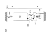
- FIG. 12A is an equivalent vibration model showing the configuration of a vibration applying mechanism 101 that is a simplified version of the vibration applying mechanism 36 of the present disclosure.
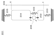
- FIG. 12B is an equivalent vibration model showing the configuration of a vibration applying mechanism 201 as a comparative example of the vibration applying mechanism 36 of the present disclosure. That is, in the configuration of the vibration imparting mechanism 101 of the present disclosure shown in FIG. 12A, the weight unit 36b is multistaged into two stages (first and second weights 36ba, 36bb) and connected to each other via the elastic element (small diameter portion 36bc). The configuration is as follows. On the other hand, in the configuration of the vibration imparting mechanism 201 of the comparative example shown in FIG. 12B, it is configured as an integral rigid body.
- 102 and 202 correspond to an abstract mass element that is the sum of the masses of the piezoelectric element 36a and the weight unit 36b, and 303 and 403 correspond to spring elements of the material of the piezoelectric element 36a, respectively.
- 103 and 203 correspond to the spring 36c, 104 and 204 correspond to the main shaft guide 40, and 105 and 205 correspond to the groove portion 35b, respectively.
- 106, 206 is an abstraction of the thrust generating portion of the piezoelectric element 36a, 107 is the small diameter portion (first elastic element) 36bc of the present disclosure, and 304 is the second weight connected to 102 by 107. , respectively, show the corresponding configurations.
- x and X indicate the positions of the weight unit 36b and the spindle guide 40 in the axial direction 109, 209, and F and (-F) indicate the excitation force (stretching force) generated in the above 106 of the piezoelectric element 36a. It is. Note that in the simplified vibration applying mechanisms 101 and 201, the buffer sheet 36e is omitted.
- equation (100) represents the transfer function from the excitation force (-F) to the weight position x of the vibration imparting mechanism 201 as a simplified comparative example shown in FIG. 12B, and the following equation ( 101) shows a transfer function from the excitation force F to the main shaft guide position X.
- m1 in equation (100) indicates the total mass (kg) of the piezoelectric element 36a and weight unit 36b, and m2 in equation (101) indicates the mass (kg) of the main shaft guide 40.
- Equation (100) and (101) are expressed in a quadratic form with antiresonance points at W1 and W2 and resonance points at W3 and W4 (see FIG. 13A).
- the unit of W1, W2, W3, and W4 is radian/second.
- the vibration characteristics on the spindle guide 40 side are expressed by equation (101) in the configuration of the comparative example, and expressed by equation (102) in the configuration of the present embodiment.
- W13 4 k2/m2 ⁇ k4/m2
- W14 2 k1/m1+k2/m1+k3/m2+k3/m3+k4/m3
- W15 4 k1/m1 ⁇ k2/m2+k1/m1 ⁇ k3/m3+k1/m1 ⁇ k4/m2+k1/m1 ⁇ k4/m3+k2/m1 ⁇ k3/m2+ k2/m1 ⁇ k3/m2+ k2/m1 ⁇ k3/m2+ k2/m1 ⁇ k3/m2+ k2/m1 ⁇ k3/m3
- W16 6 k1/m1 ⁇ k2/m2 ⁇ k3/m3+k1/m1 ⁇ k3/m3 ⁇ k4/m2+k2/m2 ⁇ k3/m3 ⁇ k4/m1 (k1: Spring constant of the fixing member that biases the second end 40b of the main shaft guide 40 in the axial direction AX from
- the peak portion of the gain for the frequency that appears in the graph of the comparative example shown by the broken line is eliminated, and one relatively gentle peak appears. Therefore, in a region where high response performance can be obtained, mechanically fatal resonance modes occur, and the occurrence of problems such as peeling of the laminated portion of the piezoelectric element 36a can be effectively suppressed. As a result, the degree of freedom in selecting the design vibration frequency can be increased compared to the configuration of the comparative example.
- the actuator for optical equipment of this embodiment has a single weight unit 36b and a washer (second weight) 136 instead of the multi-stage structure of the weight unit 36b of the first embodiment.
- the main feature is that the weights are combined into a multi-stage configuration.
- the weight unit 36b and the washer 136 are connected via the elastic element, thereby forming multi-stage weights (first and second weights).
- the washer 136 After assembling the piezoelectric element 36a, weight unit 36b, spring 36c, holder 36d, main shaft guide 40, etc., the washer 136 has its inner diameter adhered to the outer periphery of the tip of the weight unit 36b that protrudes from the center hole of the holder 36d. Fixed (elastic support). Thereby, the configuration of the comparative example without the washer 136 and the configuration of the present embodiment in which the washer 136 is attached can be compared and examined under substantially the same conditions.
- FIG. 17 is an equivalent vibration model schematically representing the demonstration model.
- the piezoelectric element 36a engages with the exterior, and the added washer 136 and elastic adhesive (first elastic element) 137 become branches extending therefrom. Therefore, except for the elastic adhesive (first elastic element) 137 and washer 136 serving as branches, the structure of this embodiment is exactly the same as the structure of the conventional example shown in FIG. 12B, and its characteristics are The basic structure (shape of frequency characteristics) will also be similar.
- this added branch portion (elastic adhesive (first elastic element) 137, washer 136) is a type of vibration damper (generally known as a dynamic vibration absorber) attached to the conventional structure. This reduces the sharp resonance points seen in the conventional example and reduces the forbidden region for setting the excitation frequency.
- vibration damper generally known as a dynamic vibration absorber
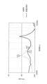
- FIG. 18 shows the results of an experiment comparing the configuration of this embodiment and a comparative example.
- the characteristics obtained with the configuration of this embodiment are shown as solid lines, and the characteristics obtained with the configuration of the comparative example are shown with broken lines.
- the very sharp extremity of the resonance point that was prominent in the comparative example indicated by the broken line was reduced by adding the configuration of the present example (washer 136 and elastic adhesive 137) as a configuration. It can be seen that the graph is relaxed and changes to a gentle slope.
- FIG. 19 shows an enlarged view of the band actually used in the graph of FIG. 18.
- the design is 1.5 times (or 0.67 times) the resonance point w101 (22kHz).
- the drive frequency is set to w102 (33kHz).
- the amplitude ratio with that of the comparative example is +4.5 dB (1.7 times), indicating the possibility of obtaining a large amplitude.
- the stepped structure can be very easily added to the conventional method, and the amplitude amount can be improved to the extent shown here.
- the weight unit 36b having a two-stage structure including the first weight 36ba and the second weight 36bb has been described as an example.
- the present invention is not limited thereto.
- two small diameter portions 36bc are provided between the two first weights 36ba and the second weight 36bb
- a third weight 36be is provided between the two small diameter portions 36bc.
- the weight unit 336b may have a multi-stage configuration of three or more stages, such as the weight unit 336b provided with a weight unit 336b.
- FIGS. 21 to 24 More specifically, a multistage configuration of three or more stages will be described below using FIGS. 21 to 24. That is, when multistage is used, the above-mentioned response equation becomes higher-order (eighth-order equation, tenth-order equation), and calculation becomes complicated.
- the significance of three stages will be explained using simulation results.
- FIG. 21 shows an abstract model for simulation of the configuration of the conventional example (Japanese Patent Application No. 2020-566172).
- reference numeral 240 is a main shaft guide model corresponding to the main shaft guide 40.
- reference numeral 236e is a buffer sheet model corresponding to the buffer sheet 36e.
- Reference numeral 236a is a piezoelectric element model corresponding to the piezoelectric element 36a.
- Reference numeral 236b is a weight unit model corresponding to the weight unit 36b.
- Reference numeral 235 is a frame model A fixed to the absolute coordinate system in the simulation.
- Reference numeral 236d indicates a frame model B fixed to the absolute coordinate system in the simulation.
- Reference numeral 255 is an adhesive bonding model in which a piezoelectric element model 236a and a weight unit model 236b are adhesively bonded.
- Reference numeral 235ab is a main shaft elastic body model, in which the main shaft guide 240 and the frame model A235 are elastically coupled.
- Reference numeral 236c is a spring elastic element model, in which the weight unit model 236b and the frame model B 236d are elastically coupled.
- FIG. 22 shows a simulation model of this embodiment, which has a configuration in which the weight unit model 236b shown in FIG. 21 is divided into three (three stages).
- reference numeral 336ba is a first weight unit model.
- Reference numeral 336bb is a second weight unit model.
- Reference numeral 336bc is a third weight unit model.
- FIG. 23 is an enlarged view of the divided first to third weight unit models 336ba, 336bb, and 336bc included in FIG. 22.
- the first weight unit model 336ba is adhesively bonded to the piezoelectric element model 236a by the adhesive bonding model 255 at its first end, and is elastically coupled to the elastic body model 336ca at its second end opposite to the first end.
- the second weight unit model 336bb is elastically coupled to the first elastic body model 336ca at its first end, and elastically coupled to the second elastic body model 336cb at its second end opposite to the first end.
- the third weight unit model 336bc is elastically coupled to the second elastic body model 336cb at its first end, and elastically coupled to the spring elastic element model 236c at its second end opposite to the first end.
- FIGS. 24A and 24B show the responsiveness of the simulation model of this embodiment.
- the results of this embodiment are shown by solid lines, and the characteristics of the conventional example are shown by dotted lines.
- FIG. 24A in this embodiment, a local gain change is seen near the target vibration frequency of 30 kHz (see the broken line A in the figure).
- FIG. 24B is an enlarged view of the area around 30 kHz in FIG. 24A.
- the above local gain change forms a local flat portion 400 (stable region) compared to the characteristic of the conventional example (dotted line).
- the vibration amount is improved by about 3 dB to 5 dB (1.4 to 1.8 times) compared to the characteristics of the conventional example (dotted line).
- the mass of the multistage weight units may be equal, or the mass of the multistage weight units may be different at a ratio other than 2:1.
- a constricted portion small diameter portion 36bc having a thinner wall thickness and lower rigidity than the first weight 36ba and second weight 36bb is used as the elastic element that connects the first weight 36ba and the second weight 36bb. I gave an example and explained. However, the present invention is not limited thereto.
- rubber, elastic resin, or the like may be used as an elastic element that connects a plurality of multi-stage weights.
- D In the above embodiment, an example has been described in which the buffer sheet 36e is provided between the end surface of the main shaft guide 40 on the first end 40a side and the end surface of the piezoelectric element 36a facing thereto.
- the present disclosure is not limited thereto.
- the end face of the main shaft guide 40 on the first end 40a side and the end face of the piezoelectric element 36a opposing thereto may be fixed with an adhesive.
- a cushioning material such as a cushioning sheet 36e is provided between the end surface of the main shaft guide 40 on the first end 40a side and the end surface of the piezoelectric element 36a facing thereto. It is possible to more effectively prevent damage to the connecting portion between the end surface of the main shaft guide 40 on the first end 40a side and the end surface of the piezoelectric element 36a facing thereto.
- the second end 40b side of the spindle guide 40 is press-fitted and fixed into the press-fit hole 35a of the guide holding frame 35.
- the present disclosure is not limited thereto.
- the fixing of the second end of the spindle guide is not limited to press-fit fixing, but may also be fixing using an adhesive or the like.
- the actuator for optical equipment of the present disclosure is applied to the third group/fourth group unit 14 included in the lens barrel 10 including a plurality of lens groups.
- the present disclosure is not limited thereto.
- the object to which the actuator for optical equipment of the present disclosure is applied is not limited to, for example, a four-group unit of a lens barrel, but may also be an actuator that drives an image sensor or other movable frame.
- the above embodiment has been described using an example in which ultrasonic vibrations are applied to the spindle guide 40 from the vibration applying mechanism 36.
- the vibration applied from the vibration applying section is not limited to ultrasonic vibration, but any vibration that reduces the frictional resistance generated between the movable frame and the spindle guide may be applied, for example, vibration in the audible range. Good too.
- the ultrasonic vibration applied from the vibration applying section is not limited to the range of 20 kHz to 60 kHz described in the above embodiment, but ultrasonic vibration outside the range may be applied.
- a solenoid spring is used as the elastic member.
- the present disclosure is not limited thereto.
- the elastic member is not particularly limited as long as it presses the guide shaft along the axial direction.
- J In the above embodiment, a configuration in which a part of the fixed frame 30 as the first frame body and the guide holding frame 35 as the second frame body are provided as separate members has been described as an example. However, the present disclosure is not limited thereto.
- the first frame and the second frame may be integrated.
- the spring 36c is coated with anti-vibration grease.
- the present invention is not limited thereto.
- it is not essential to apply anti-vibration grease to an elastic member such as a spring, and a configuration may be employed in which no anti-vibration grease is applied.
- the actuator for optical equipment of the present disclosure has the effect of effectively preventing failure of the piezoelectric element due to resonance while ensuring high response characteristics, and is therefore widely applicable as an actuator installed in various optical equipment. It is possible.
Landscapes
- Physics & Mathematics (AREA)
- General Physics & Mathematics (AREA)
- Optics & Photonics (AREA)
- Lens Barrels (AREA)
Priority Applications (3)
| Application Number | Priority Date | Filing Date | Title |
|---|---|---|---|
| JP2024516072A JP7745179B2 (ja) | 2022-04-18 | 2022-10-27 | 光学機器用アクチュエータおよびこれを備えたレンズ鏡筒 |
| EP22938591.9A EP4513245A4 (en) | 2022-04-18 | 2022-10-27 | ACTUATOR FOR OPTICAL DEVICE AND LENS TUBE THEREFOR |
| CN202280092981.XA CN118805109A (zh) | 2022-04-18 | 2022-10-27 | 光学设备用致动器以及具备该光学设备用致动器的镜头镜筒 |
Applications Claiming Priority (2)
| Application Number | Priority Date | Filing Date | Title |
|---|---|---|---|
| JP2022-068489 | 2022-04-18 | ||
| JP2022068489 | 2022-04-18 |
Publications (1)
| Publication Number | Publication Date |
|---|---|
| WO2023203793A1 true WO2023203793A1 (ja) | 2023-10-26 |
Family
ID=88419544
Family Applications (1)
| Application Number | Title | Priority Date | Filing Date |
|---|---|---|---|
| PCT/JP2022/040141 Ceased WO2023203793A1 (ja) | 2022-04-18 | 2022-10-27 | 光学機器用アクチュエータおよびこれを備えたレンズ鏡筒 |
Country Status (4)
| Country | Link |
|---|---|
| EP (1) | EP4513245A4 (https=) |
| JP (1) | JP7745179B2 (https=) |
| CN (1) | CN118805109A (https=) |
| WO (1) | WO2023203793A1 (https=) |
Citations (4)
| Publication number | Priority date | Publication date | Assignee | Title |
|---|---|---|---|---|
| JP2010074912A (ja) * | 2008-09-17 | 2010-04-02 | Konica Minolta Opto Inc | 超音波モータ |
| WO2014091656A1 (ja) | 2012-12-12 | 2014-06-19 | コニカミノルタ株式会社 | 駆動装置および撮像装置 |
| WO2019146771A1 (ja) * | 2018-01-26 | 2019-08-01 | パナソニックIpマネジメント株式会社 | 光学機器用アクチュエータおよびこれを備えたレンズ鏡筒 |
| WO2020149108A1 (ja) * | 2019-01-18 | 2020-07-23 | パナソニックIpマネジメント株式会社 | 光学機器用アクチュエータおよびこれを備えたレンズ鏡筒 |
Family Cites Families (2)
| Publication number | Priority date | Publication date | Assignee | Title |
|---|---|---|---|---|
| JP3906850B2 (ja) * | 2004-04-28 | 2007-04-18 | コニカミノルタホールディングス株式会社 | 駆動装置 |
| JP4936511B2 (ja) * | 2005-03-31 | 2012-05-23 | 富士フイルム株式会社 | 駆動装置、撮影装置及び携帯電話 |
-
2022
- 2022-10-27 WO PCT/JP2022/040141 patent/WO2023203793A1/ja not_active Ceased
- 2022-10-27 EP EP22938591.9A patent/EP4513245A4/en active Pending
- 2022-10-27 CN CN202280092981.XA patent/CN118805109A/zh active Pending
- 2022-10-27 JP JP2024516072A patent/JP7745179B2/ja active Active
Patent Citations (4)
| Publication number | Priority date | Publication date | Assignee | Title |
|---|---|---|---|---|
| JP2010074912A (ja) * | 2008-09-17 | 2010-04-02 | Konica Minolta Opto Inc | 超音波モータ |
| WO2014091656A1 (ja) | 2012-12-12 | 2014-06-19 | コニカミノルタ株式会社 | 駆動装置および撮像装置 |
| WO2019146771A1 (ja) * | 2018-01-26 | 2019-08-01 | パナソニックIpマネジメント株式会社 | 光学機器用アクチュエータおよびこれを備えたレンズ鏡筒 |
| WO2020149108A1 (ja) * | 2019-01-18 | 2020-07-23 | パナソニックIpマネジメント株式会社 | 光学機器用アクチュエータおよびこれを備えたレンズ鏡筒 |
Non-Patent Citations (1)
| Title |
|---|
| See also references of EP4513245A4 |
Also Published As
| Publication number | Publication date |
|---|---|
| JPWO2023203793A1 (https=) | 2023-10-26 |
| EP4513245A4 (en) | 2025-07-30 |
| JP7745179B2 (ja) | 2025-09-29 |
| CN118805109A (zh) | 2024-10-18 |
| EP4513245A1 (en) | 2025-02-26 |
Similar Documents
| Publication | Publication Date | Title |
|---|---|---|
| CN113272701B (zh) | 光学设备用致动器以及具备光学设备用致动器的镜头镜筒 | |
| JP4931182B2 (ja) | 駆動装置 | |
| US9530953B2 (en) | Vibration-type actuator, image pickup apparatus, and stage | |
| JP7336740B2 (ja) | 光学機器用アクチュエータおよびこれを備えたレンズ鏡筒 | |
| KR100777630B1 (ko) | 구동장치 | |
| JP7313909B2 (ja) | 振動波モータおよび電子機器。 | |
| JP4931425B2 (ja) | 駆動装置 | |
| JP7046614B2 (ja) | 振動型アクチュエータ及び電子機器 | |
| JP2000050657A (ja) | 電気機械変換素子を使用したアクチエ−タ | |
| US6809461B2 (en) | Drive unit | |
| JP7745179B2 (ja) | 光学機器用アクチュエータおよびこれを備えたレンズ鏡筒 | |
| JP2016027780A (ja) | 振動型アクチュエータ、レンズ鏡筒、撮像装置及び自動ステージ | |
| JP2003324979A (ja) | 駆動機構 | |
| JP2016140180A (ja) | 振動型駆動装置およびこれを駆動源とする装置 | |
| JP6812510B2 (ja) | 振動型アクチュエータ及びそれを有する電子機器 | |
| CN111034213B (zh) | 乐器 | |
| JP2016158386A (ja) | 振動型駆動装置、レンズ鏡筒及び撮像装置 | |
| JP6753756B2 (ja) | 駆動装置、及びカメラモジュール | |
| JP6948102B2 (ja) | リニア駆動装置、カメラ装置及び電子機器 | |
| JP2024090648A (ja) | 振動型アクチュエータ、レンズ鏡筒、撮像装置およびステージ装置 | |
| Benassi | Feedback control of vibration with inertial actuators | |
| WO2010032624A1 (ja) | 圧電アクチュエータ | |
| JPS62262674A (ja) | 振動波モ−タ | |
| JP2019154145A (ja) | 振動波モータ及びレンズ装置 | |
| JP2009229710A (ja) | 駆動装置 |
Legal Events
| Date | Code | Title | Description |
|---|---|---|---|
| 121 | Ep: the epo has been informed by wipo that ep was designated in this application |
Ref document number: 22938591 Country of ref document: EP Kind code of ref document: A1 |
|
| WWE | Wipo information: entry into national phase |
Ref document number: 202280092981.X Country of ref document: CN |
|
| ENP | Entry into the national phase |
Ref document number: 2024516072 Country of ref document: JP Kind code of ref document: A |
|
| WWE | Wipo information: entry into national phase |
Ref document number: 2022938591 Country of ref document: EP |
|
| NENP | Non-entry into the national phase |
Ref country code: DE |
|
| ENP | Entry into the national phase |
Ref document number: 2022938591 Country of ref document: EP Effective date: 20241118 |