WO2023203633A1 - 固定子、電動機及び送風機 - Google Patents
固定子、電動機及び送風機 Download PDFInfo
- Publication number
- WO2023203633A1 WO2023203633A1 PCT/JP2022/018128 JP2022018128W WO2023203633A1 WO 2023203633 A1 WO2023203633 A1 WO 2023203633A1 JP 2022018128 W JP2022018128 W JP 2022018128W WO 2023203633 A1 WO2023203633 A1 WO 2023203633A1
- Authority
- WO
- WIPO (PCT)
- Prior art keywords
- stator
- magnetic flux
- winding
- electric motor
- stator core
- Prior art date
- Legal status (The legal status is an assumption and is not a legal conclusion. Google has not performed a legal analysis and makes no representation as to the accuracy of the status listed.)
- Ceased
Links
Images


Classifications
-
- H—ELECTRICITY
- H02—GENERATION; CONVERSION OR DISTRIBUTION OF ELECTRIC POWER
- H02K—DYNAMO-ELECTRIC MACHINES
- H02K3/00—Details of windings
- H02K3/32—Windings characterised by the shape, form or construction of the insulation
- H02K3/34—Windings characterised by the shape, form or construction of the insulation between conductors or between conductor and core, e.g. slot insulation
Definitions
- the present disclosure relates to a stator, a motor, and a blower.
- Patent Document 1 has a problem in that the insulating part is deformed due to stress generated in the insulating part when the winding is wound. When the deformed insulation presses on the extension and the extension comes into contact with the rotor, noise is generated.
- the present disclosure aims to suppress deformation of an insulating member in a stator.
- a stator includes a stator main body including a stator core and a magnetic flux intake member provided at an axial end of the stator core, and a winding wound around the stator core. and a first insulating member that insulates the stator main body and the winding, and the first insulating member includes a first insulating member provided between the magnetic flux intake member and the winding. The thickness of the first portion in the radial direction of the stator core becomes thinner toward the end of the first insulating member in the axial direction.
- An electric motor includes the stator and rotor described above.
- a blower according to another aspect of the present disclosure includes the above-described electric motor and an impeller driven by the electric motor.
- deformation of the insulating member in the stator can be suppressed.
- FIG. 1 is a partial side view schematically showing a part of the configuration of an electric motor according to Embodiment 1.
- FIG. FIG. 2 is a cross-sectional view of the stator shown in FIG. 1 taken along line A2-A2.
- FIG. 3 is a perspective view showing a part of the structure of the stator main body shown in FIGS. 1 and 2.
- FIG. 3 is a cross-sectional view schematically showing a part of the structure of the stator shown in FIGS. 1 and 2.
- FIG. FIG. 5 is an enlarged sectional view showing the configuration around the magnetic flux intake member shown in FIG. 4.
- FIG. FIG. 3 is a cross-sectional view schematically showing a part of the configuration of a stator according to Modification 1 of Embodiment 1.
- FIG. 7 is a cross-sectional view schematically showing a part of the structure of a stator according to a second modification of the first embodiment.
- FIG. FIG. 3 is a cross-sectional view schematically showing a part of the structure of a stator according to a second embodiment.
- FIG. 7 is a cross-sectional view schematically showing a part of the structure of a stator according to a modification of the second embodiment.
- FIG. 7 is a cross-sectional view schematically showing a part of the configuration of an electric motor according to a third embodiment.
- FIG. 7 is a cross-sectional view schematically showing a part of the structure of a stator according to a fourth embodiment.
- FIG. 7 is a cross-sectional view schematically showing a part of the structure of a stator according to a modification of the fourth embodiment.
- FIG. 7 is a partial cross-sectional view schematically showing the configuration of a blower according to a fifth embodiment.
- the z-axis is a coordinate axis parallel to the axis of the motor rotor shaft.
- the x-axis is a coordinate axis perpendicular to the z-axis.
- the y-axis is a coordinate axis perpendicular to both the x-axis and the z-axis.
- FIG. 1 is a partial side view schematically showing a part of the configuration of electric motor 100 according to the first embodiment.
- electric motor 100 includes a stator 1 and a rotor 5.
- the rotor 5 is arranged inside the stator 1. That is, the electric motor 100 is an inner rotor type electric motor.
- the rotor 5 has a shaft 51 as a rotating shaft and a permanent magnet 52 as a rotor body.
- the rotor 5 is rotatable around the axis A of the shaft 51.
- a direction along the circumference of a circle centered on the axis A of the shaft 51 will be referred to as a "circumferential direction C.”
- the z-axis direction is also called the "axial direction”
- the direction orthogonal to the axial direction is also called the "radial direction”.
- the permanent magnet 52 is attached to the shaft 51.
- the permanent magnet 52 is a cylindrical magnet that is long in the z-axis direction.
- N poles and S poles are alternately formed.
- the rotor body of the rotor 5 may include a rotor core fixed to the shaft 51 and a permanent magnet attached to the rotor core.
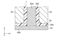
- FIG. 2 is a cross-sectional view of the stator 1 shown in FIG. 1 taken along the line A2-A2.
- the stator 1 includes a stator main body 10, a winding 20, and an insulator 30 as a first insulating member.
- FIG. 3 is a perspective view showing a part of the structure of the stator main body 10 shown in FIGS. 1 and 2. As shown in FIG. 3, the stator main body 10 includes a stator core 40 and magnetic flux intake members 61 and 62.
- the stator core 40 has a yoke 41 extending in the circumferential direction C and a plurality of teeth 42.
- the plurality of teeth 42 are arranged at predetermined intervals in the circumferential direction C.
- a slot 43 which is a space in which the winding 20 and the insulator 30 (see FIGS. 1 and 2) are accommodated, is provided between two teeth 42 adjacent to each other in the circumferential direction C among the plurality of teeth 42.
- the plurality of teeth 42 face the rotor 5 (see FIG. 1) in the radial direction.
- Each tooth 42 of the plurality of teeth 42 has a tooth main body portion 42a and a tooth tip portion 42b.
- the teeth main body portion 42a extends radially inward from the yoke 41.
- the winding 20 (see FIG. 2) is wound around the tooth body portion 42a via the insulator 30.
- the tooth tip portion 42b is disposed radially inside the tooth body portion 42a, and is wider in the circumferential direction C than the tooth body portion 42a.
- the tooth tip portion 42b has an end face 42c facing the +z-axis direction and an end face 42d facing the ⁇ z-axis direction. End surfaces 42c and 42d on both sides in the z-axis direction of the tooth tip portion 42b constitute ends of the stator core 40 in the z-axis direction.
- the stator core 40 has an end face 40a facing the +z-axis direction, which is one end face in the axial direction, and an end face 40b facing the ⁇ z-axis direction, which is the other end face in the axial direction.
- the above-mentioned permanent magnet 52 has an end face 52a that is one end face in the axial direction, which faces the +z-axis direction, and an end face 52b, which is the other end face, that faces the ⁇ z-axis direction.
- the first length (hereinafter also referred to as "axial length") of the stator core 40 in the z-axis direction is L1
- the second length of the permanent magnet 52 in the z-axis direction is L2.
- the length L1 is shorter than the length L2. That is, the length L1 and the length L2 satisfy the following formula (1). L1 ⁇ L2 (1)
- FIG. 4 is a cross-sectional view schematically showing a part of the structure of the stator 1 shown in FIGS. 1 and 2.
- the stator core 40 has a plurality of electromagnetic steel plates 45 stacked in the z-axis direction. Since the length L1 of the stator core 40 in the z-axis direction is shorter than the length L2 of the permanent magnet 52 in the z-axis direction, the number of electromagnetic steel plates 45 is reduced, so that the cost of the stator core 40 can be reduced. can. Therefore, the cost of electric motor 100 can be reduced. Furthermore, since the length (circumferential length) of the winding 20 is also shortened, the resistance value of the winding 20 can be reduced. Therefore, reduction in loss in the electric motor 100 can be prevented. That is, the efficiency of electric motor 100 can be improved.
- the end face 40a facing the +z-axis direction and the end face 40b facing the ⁇ z-axis direction of the stator core 40 are the same as the end face 52a facing the +z-axis direction and the end face 52b facing the ⁇ z-axis direction of the permanent magnet 52. is located between.
- at least one end surface of the end surface 40a facing the +z-axis direction and the end surface 40b facing the ⁇ z-axis direction of the stator core 40 faces the ⁇ z-axis direction with the end surface 52a of the permanent magnet 52 facing the +z-axis direction. It suffices if it is disposed between the end surface 52b and the end surface 52b.
- the end surface 40b of the stator core 40 facing the -z-axis direction may be located axially outside the end surface 52b of the permanent magnet 52 facing the -z-axis direction.
- the length L1 of the stator core 40 in the z-axis direction is shorter than the length L2 of the permanent magnet 52 in the z-axis direction.
- the axial length of the stator core and the rotor body are the same.
- permanent magnets with high magnetic force are expensive.
- an inexpensive permanent magnet with low magnetic force for example, a ferrite magnet
- the volume of the motor becomes large in order to compensate for the decrease in magnetic force. Therefore, the cost of the electromagnetic steel plate 45 (see FIG. 4) and the winding increases.
- the length L1 of the stator core 40 in the z-axis direction is shorter than the length L2 of the permanent magnet 52 in the z-axis direction. Since the number of electromagnetic steel plates 45 provided in the stator core 40 is reduced, the cost of the stator core 40 can be reduced. Therefore, the cost of electric motor 100 can be reduced.
- the length of the stator core in the z-axis direction is made shorter than the length of the rotor main body (permanent magnet 52 in the first embodiment) in the z-axis direction, the magnetic flux of the permanent magnets taken into the stator core Since the amount decreases, the efficiency of the electric motor decreases.
- the magnetic flux generated at the end of the rotor body in the z-axis direction that does not face the stator core in the radial direction (hereinafter also referred to as an "overhang") becomes difficult to flow to the stator core. In this way, when the amount of magnetic flux flowing from the rotor body to the stator core decreases, the output and efficiency of the motor may decrease.
- the stator main body 10 has magnetic flux capturing members 61 and 62 made of a magnetic material that captures the magnetic flux of the permanent magnet 52. This makes it easier for the magnetic flux generated in the overhang portion of the permanent magnet 52 to flow to the stator core 40 and the winding 20 via the magnetic flux intake members 61 and 62. Therefore, according to the first embodiment, it is possible to reduce the cost of electric motor 100 while preventing a decrease in the output and efficiency of electric motor 100. Therefore, even if an inexpensive low-magnetic-force magnet (for example, a ferrite magnet) is used as the permanent magnet 52 in the rotor 5 of the electric motor 100, the magnetic flux intake members 61 and 62 will not absorb the magnetic flux of the permanent magnet.
- an inexpensive low-magnetic-force magnet for example, a ferrite magnet
- the magnetic flux intake members 61 and 62 are, for example, metal pieces made of a metal material. Specifically, the magnetic flux intake members 61 and 62 are iron pieces made of iron.
- the plurality of magnetic flux intake members 61 and 62 are arranged at intervals in the circumferential direction C. Specifically, the magnetic flux intake member 61 is arranged on the end face 42c of the tooth tip 42b facing the +z-axis direction, and the magnetic flux intake member 62 is arranged on the end face 42d of the tooth tip 42b facing the ⁇ z-axis direction. has been done.
- the magnetic flux intake members 61 and 62 are arranged at the tooth tip portions 42b of the teeth 42.
- the magnetic flux capturing members 61, 62 are arranged closer to the permanent magnet 52 (see FIG. 1).
- the magnetic flux of the permanent magnet 52 is easily captured by the magnetic flux capture members 61 and 62.
- the magnetic flux intake members 61 and 62 will be collectively referred to as the "magnetic flux intake member 60.” Note that, as shown in FIG.
- the stator main body 10 can be realized without having the magnetic flux intake member 62.
- the magnetic flux intake member 60 may be disposed on at least one of the end surfaces 42c facing the +z-axis direction and the end surface 42d facing the ⁇ z-axis direction of the tooth tip 42b.
- the configuration of the insulator 30 will be explained using FIGS. 2, 4, and 5.
- the insulator 30 is provided between the stator main body 10 and the winding 20. Insulator 30 insulates stator main body 10 and winding 20.
- the insulator 30 has a first insulating part 30a and a second insulating part 30b.
- the first insulating portion 30 a is a portion of the insulator 30 that insulates the tooth tip portion 42 b and the winding 20 and insulates the magnetic flux intake member 60 and the winding 20 .
- the second insulating portion 30b is a portion of the insulator 30 that insulates the tooth body portion 42a and the winding 20.
- stator main body 10 includes the magnetic flux intake member 60, it is possible to reduce the cost of the stator 1 and prevent a decrease in the efficiency and output of the electric motor 100.
- stress from the winding 20 acts on the surface of the first insulating portion 30a of the insulator 30 that faces the winding 20 (that is, the radially outward facing surface 31). Stress (hereinafter also referred to as “winding stress F 1 , F 2 ”) generated on the radially outward surface 31 of the insulator 30 occurs when the winding 20 is wound around the teeth 42 .
- the insulator 30 may be deformed due to winding stress. Specifically, the radially outward surface 31 of the insulator 30 may fall toward the magnetic flux intake member 61 due to winding stress. In this case, when the insulator 30 contacts the magnetic flux intake member 61 and presses the magnetic flux intake member 60, the magnetic flux intake member 61 also deforms toward the rotor 5, and the magnetic flux intake member 61 and the rotor 5 may come into contact.
- the teeth 42 are difficult to deform. This is because the teeth 42 have a T-shape when viewed in the z-axis direction and have a large moment of inertia. Therefore, the portion of the insulator 30 that is supported by the teeth 42 (specifically, the teeth tips 42b) is unlikely to be deformed by the winding stress F2 .
- the shape of the magnetic flux intake member 61 when viewed in the z-axis direction is rectangular, the moment of inertia of the magnetic flux intake member 61 is smaller than the moment of inertia of the tooth 42 . Therefore, a portion of the insulator 30 that overlaps with the magnetic flux intake member 61 in the z-axis direction is easily deformed.
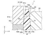
- FIG. 5 is an enlarged sectional view showing the configuration around the magnetic flux intake member 61 shown in FIG. 4.
- the thickness in the radial direction of the first portion 33 which is the portion of the insulator 30 provided between the magnetic flux intake member 61 and the winding 20
- the thickness t1 becomes thinner toward the end portion 30e of the insulator 30 in the z-axis direction (that is, the end portion facing outward in the axial direction).
- the thickness t1 becomes thinner toward the end 30e of the insulator 30 in the z-axis direction.
- the winding stress F1 acting on the insulator 30 can be reduced.
- the thickness t1 is thinner than the thickness t2.
- the radially outward surface 31 of the insulator 30 has a first inclined portion 31a.
- the first inclined portion 31a is inclined such that the closer it gets to the end 30e of the insulator 30 in the z-axis direction, the closer the radial position is to the magnetic flux intake member 60 (that is, the farther away from the winding 20).
- the first inclined portion 31a is inclined such that the closer it gets to the end 30e of the insulator 30 in the z-axis direction, the shorter the radial distance from the axis A (FIG. 1). .
- the first inclined portion 31a is provided in a portion of the radially outward surface 31 of the insulator 30 that overlaps with the magnetic flux intake member 61 in the z-axis direction.
- the winding stress F1 acting on the first inclined portion 31a is lower than the winding stress F2 acting on the portion of the radially outward facing surface 31 where the position in the z-axis direction overlaps with the teeth 42 . be able to. Therefore, since the insulator 30 is less likely to be deformed by the winding stress F1 , the magnetic flux intake member 61 and the rotor 5 are less likely to come into contact with each other. Therefore, generation of noise in electric motor 100 can be suppressed.
- the surface 32 of the insulator 30 facing the magnetic flux intake member 61 (that is, the surface facing inward in the radial direction) has the second inclined portion 32a.
- the second inclined portion 32a is inclined so that the closer the second inclined portion 32a is to the end 30e of the insulator 30 in the z-axis direction, the closer the radial position is to the winding 20 (that is, the farther away from the magnetic flux intake member 60).
- the second inclined portion 32a is inclined such that the radial distance from the axis A (FIG. 1) increases as it approaches the end 30e of the insulator 30 in the z-axis direction. .
- the second inclined portion 32a is provided at a portion of the radially inward surface 32 of the insulator 30 that overlaps with the magnetic flux intake member 61 in the z-axis direction. This makes it difficult for the insulator 30 and the magnetic flux intake member 61 to come into contact with each other. Therefore, the generation of noise in the electric motor 100 can be further suppressed.
- the insulator 30 has the first slope portion 61a and the second slope portion 62a.
- the radial thickness t1 of the first portion 33 of the insulator 30 provided between the magnetic flux intake member 61 and the winding 20 increases as it approaches the end 30e of the insulator 30 in the z-axis direction. , is thinner.
- the insulator 30 can be realized even if it has one of the first slope portion 61a and the second slope portion 62a.
- the insulator 30 has a first portion 33 that insulates the magnetic flux intake member 60 and the winding 20, and a second portion 34 that insulates the stator core 40 and the winding 20, which are separate bodies. Good too.
- the thickness t1 becomes thinner as it approaches the end of the insulator 30 in the z-axis direction. You can leave it there.
- the winding 20 is wound around the teeth 42 of the stator core 40.
- the winding 20 is, for example, aluminum wire, which is cheaper than copper wire. Therefore, the cost of electric motor 100 can be reduced.
- the axial length of stator core 40 ie, length L1
- the axial length of permanent magnet 52 ie, length L2
- the resistance value of the winding 20 also becomes smaller.
- the length L1 of the stator core 40 in the z-axis direction is shorter than the length L2 of the permanent magnet 52 in the z-axis direction. This reduces the number of electromagnetic steel sheets 45 used in the stator core 40, so the cost of the stator 1 can be reduced. Therefore, the cost of electric motor 100 can be reduced.
- the stator 1 includes a magnetic flux capturing member 60 made of a magnetic material that captures the magnetic flux of the permanent magnet 52.
- the magnetic flux generated at the overhang portion of the permanent magnet 52 flows to the stator core 40 and the winding 20 via the magnetic flux intake member 60. Therefore, a decrease in the amount of magnetic flux flowing from the permanent magnet 52 to the stator 1 can be suppressed. Therefore, a decrease in the output and efficiency of electric motor 100 can be suppressed.
- the insulator 30 has the first portion 33 provided between the magnetic flux intake member 60 and the winding 20, and the thickness of the first portion 33 in the radial direction is t1 becomes thinner toward the end 30e of the insulator 30 in the z-axis direction.
- the winding stress F1 acting on the insulator 30 can be reduced. Therefore, deformation of the insulator 30 due to the winding stress F 1 (that is, falling toward the magnetic flux intake member 60 side) can be suppressed. Therefore, since the magnetic flux intake member 60 also becomes difficult to deform, it becomes difficult for the magnetic flux intake member 60 and the rotor 5 to come into contact with each other, so that the generation of noise in the electric motor 100 can be suppressed.
- the radially outward surface 31 of the insulator 30, which is the surface facing the winding 20, has the first inclined portion 31a.
- the first inclined portion 31a is inclined so that its radial position approaches the magnetic flux intake member 60 (that is, moves away from the winding 20) as it approaches the end 30e of the insulator 30 in the +z-axis direction. This makes it difficult for the insulator 30 to be deformed by the winding stress F1 , making it difficult for the magnetic flux intake member 60 and the rotor 5 to come into contact with each other. Therefore, the generation of noise in the electric motor 100 can be suppressed.
- the radially inward surface 32 of the insulator 30, which is the surface facing the magnetic flux intake member 60, has the second inclined portion 32a.
- the second inclined portion 32a is inclined so that the closer it is to the end 30e of the insulator 30 in the +z-axis direction, the closer the radial position is to the winding 20 (that is, the farther away from the magnetic flux intake member 60). This makes it difficult for the insulator 30 and the magnetic flux intake member 60 to come into contact with each other. Therefore, the generation of noise in the electric motor 100 can be further suppressed.
- the electric motor 100 is an inner rotor type electric motor is explained as an example, but even if it is an outer rotor type electric motor in which the rotor 5 is disposed outside the stator 1, The above effects can be achieved.
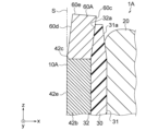
- FIG. 6 is a cross-sectional view schematically showing a part of the configuration of a stator 1A according to a first modification of the first embodiment.
- components that are the same as or correspond to those shown in FIG. 4 are given the same reference numerals as those shown in FIG.
- Stator 1A according to Modification 1 of Embodiment 1 differs from stator 1 according to Embodiment 1 in the shape of magnetic flux intake member 60A.
- the stator 1A according to the first modification of the first embodiment is the same as the stator 1 according to the first embodiment. Therefore, in the following description, reference will be made to FIG.
- the stator 1A includes a stator main body 10A, a winding 20, and an insulator 30.
- the stator main body 10A includes a stator core 40 including teeth 42, and a magnetic flux intake member 60A disposed on an end surface 42c of the tooth tip 42b facing the +z-axis direction.
- the radially outward facing surface 60c of the magnetic flux intake member 60A is in contact with the second inclined portion 32a of the insulator 30. This makes it difficult for the magnetic flux intake member 60A to come into contact with the rotor 5 (see FIG. 1). Therefore, the generation of noise in the stator 1A can be further suppressed.
- the radially inward surface 60d of the magnetic flux intake member 60A is inclined so that the radial position approaches the winding 20 as it approaches the end 60e of the magnetic flux intake member 60A in the +z-axis direction.
- the radially inward surface 60d is located closer to the insulator 30 than the cylindrical surface S including the radially inward surface 42e of the tooth tip 42b. This makes it difficult for the magnetic flux intake member 60A to come into contact with the rotor 5 (see FIG. 1). Therefore, the generation of noise in the stator 1A can be further suppressed.
- FIG. 7 is a sectional view schematically showing a part of the configuration of a stator 1B according to a second modification of the first embodiment.
- components that are the same as or correspond to those shown in FIG. 4 are given the same reference numerals as those shown in FIG.
- the stator 1B according to the second modification of the first embodiment differs from the stator 1 according to the first embodiment in that it further includes a molded resin part 70.
- the stator 1B according to the second modification of the first embodiment is the same as the stator 1 according to the first embodiment.
- the stator 1B includes a stator main body 10, a winding 20, an insulator 30, and a molded resin part 70 as a second insulating member.
- the mold resin part 70 is made of, for example, a thermosetting resin.
- the mold resin part 70 is molded, for example, by injection molding. Moreover, the molded resin part 70 is integrated with the stator main body 10, the winding 20, and the insulator 30 by integral molding.
- the molded resin part 70 fixes the magnetic flux intake member 60 to the stator core 40. This improves the rigidity of the stator main body 10, so that vibration of the magnetic flux intake member 60 due to electromagnetic force can be suppressed. Therefore, it is possible to realize a reduction in noise of the electric motor having the stator 1B.
- the molded resin part 70 fixes the insulator 30 to the stator core 40. Thereby, deformation of the insulator 30 due to winding stress can be further suppressed.
- the molded resin part 70 fixes the winding 20 to the stator core 40. This prevents the winding 20 from vibrating due to magnetic force or Lorentz force when energized, so it is possible to further suppress the generation of noise in the stator 1B.
- the winding wire 20 is an aluminum wire
- the tensile strength of the aluminum wire is lower than the tensile strength of the copper wire. Therefore, the tensile strength during the winding operation of the winding 20 around the stator core 40 is reduced, and the force for fixing the winding 20 to the stator core 40 is reduced.
- the winding 20 tends to vibrate.
- the molded resin part 70 covers the winding 20. Thereby, even if a current is applied to the winding 20 made of aluminum wire, vibration of the winding 20 can be suppressed.
- the winding 20 is an aluminum wire and the winding 20 is covered with the molded resin part 70, the cost of the stator 1B can be further reduced, and the generation of noise in the stator 1B can be further suppressed. can do.
- the winding 20 may be an aluminum alloy wire having a tensile strength greater than that of the aluminum wire.
- the stator 1B further includes a molded resin portion 70 that fixes the magnetic flux intake member 60 to the stator core 40. This improves the rigidity of the stator main body 10, so that vibration of the magnetic flux intake member 60 due to electromagnetic force can be suppressed.
- the molded resin portion 70 fixes the insulator 30 to the stator core 40. Thereby, deformation of the insulator 30 due to winding stress can be further suppressed.
- the molded resin portion 70 fixes the winding 20 to the stator core 40. This prevents the winding 20 from vibrating due to magnetic force or Lorentz force when energized, so that the generation of noise in the stator 1B can be further suppressed.
- FIG. 8 is a cross-sectional view schematically showing a part of the structure of the stator 2 according to the second embodiment.
- components that are the same as or correspond to those shown in FIG. 4 are given the same reference numerals as those shown in FIG.
- the stator 2 according to the second embodiment differs from the stator 1 according to the first embodiment in the shape of the insulator 230.
- the stator 2 according to the second embodiment is the same as the stator 1 according to the first embodiment. Therefore, in the following description, reference will be made to FIG.
- the stator 2 includes a stator main body 10, a winding 20, and an insulator 230.
- the radial position of the entire radially outward facing surface 231 of the insulator 230 (that is, the surface facing the winding 20) approaches the magnetic flux intake member 60 as it approaches the end 30e of the insulator 230 in the +z-axis direction. (i.e., away from winding 20).
- the radially outward surface 231 of the insulator 230 is arranged such that the closer it gets to the +z-axis end 30e of the insulator 230, the shorter the radial distance from the axis A (FIG. 1). It is sloping.
- the winding stresses F 11 , F 12 , F 13 acting on the radially outward facing surface 231 become smaller as they get closer to the end 30e in the +z-axis direction. Therefore, compared to the configuration shown in FIG. 4, the stress acting on the portion of the radially outward facing surface 231 where the boundary between the magnetic flux intake member 60 and the stator core 40 overlaps in the z-axis direction can be reduced. can be reduced. Therefore, since the insulator 230 becomes difficult to deform due to winding stress, it becomes difficult for the magnetic flux intake member 60 and the rotor 5 (see FIG. 1) to come into contact with each other. Therefore, generation of noise in the stator 2 can be suppressed.
- the winding 20 has a protrusion (that is, a coil end) 21 that covers an end surface 230c of the insulator 230 facing in the +z-axis direction.
- the axial height H2 of the radially inner portion of the protrusion 21 from the end surface 230c is the axial height H2 of the radially central portion of the protrusion 21 from the end surface 230c. Lower than H 1 .
- the axial height of the protrusion 21 of the winding 20 from the end surface 230c decreases as it approaches the radially outward surface 231 of the insulator 230.
- the winding 20 has the protrusion 21 that protrudes in the axial direction from the end face 230c of the insulator 230 facing the +z-axis direction, and the height of the radially inner portion of the protrusion 21 is increased.
- the height H 2 is lower than the height H 1 of the radially central portion of the protrusion 21 .
- FIG. 9 is a cross-sectional view schematically showing a part of the configuration of a stator 2A according to a modification of the second embodiment.
- components that are the same as or correspond to those shown in FIG. 8 are given the same reference numerals as those shown in FIG.
- the stator 2A according to the modification of the second embodiment differs from the stator 2 according to the second embodiment in that a gap d is provided between the insulator 230 and the winding 20.
- the stator 2A according to the modification of the second embodiment is the same as the stator 2 according to the second embodiment.
- a gap d is provided between the insulator 230 and the winding 20 in the radial direction. Specifically, a gap d is created between the winding 20 and a portion of the radially outward facing surface 231 of the insulator 230 where the +z-axis facing end surface 42c of the tooth tip 42b overlaps in the z-axis direction. is provided. This makes it difficult for winding stress to act on the insulator 230. Therefore, deformation of the insulator 230 due to winding stress can be further suppressed.
- a gap d is provided between the insulator 230 and the winding 20.
- deformation of the insulator 230 due to winding stress can be further suppressed. Therefore, since the magnetic flux intake member 60 also becomes difficult to deform, it becomes difficult for the magnetic flux intake member 60 and the rotor 5 to come into contact with each other, so that it is possible to suppress the generation of noise in the electric motor.
- FIG. 10 is a cross-sectional view schematically showing a part of the configuration of electric motor 300 according to the third embodiment.
- the electric motor 300 according to the third embodiment is different from the electric motor 100 according to the first embodiment in that the stator 3 does not have the magnetic flux intake member 62.
- electric motor 300 according to the third embodiment is the same as electric motor 100 according to the first embodiment. Therefore, in the following description, reference is made to FIGS. 1 and 2.
- the electric motor 300 has a stator 3 and a rotor 5.
- the stator 3 includes a stator main body 310, a winding 20, and an insulator 30.
- the stator main body 310 has a stator core 40 and a magnetic flux intake member 61.
- the stator 3 only has the magnetic flux intake member 61 disposed on the end surface 42c of the tooth tip 42b facing the +z-axis direction. Thereby, the number of parts in the electric motor 300 can be reduced, and the assembly process of the electric motor 300 can be simplified.
- a portion 32c of the radially inward surface 32 of the insulator 30 facing the magnetic flux intake member 61 and a portion 32c opposite to the radially inward surface 32b of the tooth tip 42b is arranged closer to the winding 20 than the surface 42e. This increases the distance between the outer circumferential surface 52c of the permanent magnet 52 and the radially inward surface 32 of the insulator 30. Therefore, even if the insulator 30 is deformed by winding stress, contact between the radially inward surface 32 of the insulator 30 and the rotor 5 can be prevented.
- the magnetic flux intake member 61 is the only magnetic flux intake member provided in the stator 3 of the electric motor 300. As a result, the number of parts in the electric motor 300 can be reduced, and the assembly process for the electric motor 300 can be simplified.
- the center position P3 of the rotor 5 in the z-axis direction is shifted toward the magnetic flux intake member 61 with respect to the center position P3 of the stator 3 in the z-axis direction. This makes it easier for the magnetic flux capturing member 61 to capture the magnetic flux of the permanent magnet 52. Therefore, a decrease in efficiency and output of electric motor 300 can be prevented.
- the radially inward surface 32 of the insulator 30 is arranged closer to the winding 20 than the radially inward surface 42e of the tooth tip 42b. This increases the distance between the outer circumferential surface 52c of the permanent magnet 52 and the radially inward surface 32 of the insulator 30. Therefore, even if the insulator 30 is deformed by winding stress, contact between the radially inward surface 32 of the insulator 30 and the rotor 5 can be prevented.
- FIG. 11 is a cross-sectional view schematically showing a part of the structure of the stator 4 according to the fourth embodiment.
- components that are the same as or correspond to those shown in FIG. 4 are given the same reference numerals as those shown in FIG.
- the stator 4 according to the fourth embodiment differs from the stator 1 according to the first embodiment in the configuration of the magnetic flux intake member 460. In other respects, the stator 4 according to the fourth embodiment is the same as the stator 1 according to the first embodiment.
- the stator 4 includes a stator main body 410, a winding 20, and an insulator 30.
- the stator main body 410 has a stator core 40 and a magnetic flux intake member 460.
- the magnetic flux intake member 460 includes a plurality of magnetic bodies 465 stacked in the z-axis direction. Thereby, eddy current loss in the magnetic flux intake member 460 can be reduced compared to a configuration in which the magnetic flux intake member 60 is formed from one magnetic body.
- the magnetic flux intake member 460 includes a plurality of magnetic bodies 465 stacked in the z-axis direction. Thereby, eddy current loss in the magnetic flux intake member 460 can be reduced compared to a configuration in which the magnetic flux intake member 60 is formed from one magnetic body.
- FIG. 12 is a cross-sectional view schematically showing a part of the configuration of a stator 4A according to a modification of the fourth embodiment.
- components that are the same as or correspond to those shown in FIG. 11 are given the same reference numerals as those shown in FIG.
- a stator 4A according to a modification of the fourth embodiment is different from the stator 4 according to the fourth embodiment in the stacking direction of the plurality of magnetic bodies 465A.
- the stator 4A according to the modification of the fourth embodiment is the same as the stator 4 according to the fourth embodiment. Therefore, in the following description, reference is made to FIGS. 1 and 4.
- the stator 4A includes a stator main body 410A, a winding 20, and an insulator 30.
- the stator main body 410A includes a stator core 40 and a magnetic flux intake member 460A.
- the magnetic flux intake member 460A includes a plurality of magnetic bodies 465A.
- the plurality of magnetic bodies 465A are stacked in a radial direction perpendicular to the axial direction (z-axis direction).
- the stacking direction of the plurality of magnetic bodies 465A is perpendicular to the stacking direction of the electromagnetic steel plates 45 (see FIG. 4) of the stator core 40.
- This makes it easier for the magnetic flux of the permanent magnet 52 (see FIG. 1) taken into the plurality of magnetic bodies 465A to flow toward the stator core 40.
- the magnetic flux of the permanent magnet 52 passes between adjacent magnetic bodies 465A. It is possible to suppress magnetic flux loss when
- the plurality of magnetic bodies 465A are stacked in the radial direction, which is the direction perpendicular to the axial direction. This makes it easier for the magnetic flux of the permanent magnets 52 taken in from the rotor 5 to flow toward the stator core 40. Further, it is possible to suppress magnetic flux loss when the magnetic flux of the permanent magnet 52 passes between the adjacent magnetic bodies 465A.
- FIG. 13 is a partial cross-sectional view schematically showing the configuration of a blower 500 according to the fifth embodiment.
- the blower 500 includes an electric motor 100 and an impeller (also referred to as "blade” or "fan") 501.
- the impeller 501 is driven by the electric motor 100 to generate airflow.
- the rotor 5 includes a shaft 51, a permanent magnet 52, a first bearing 53, and a second bearing 54.
- the shaft 51 protrudes from the stator 1 toward the +z-axis side.
- the protruding side of the shaft 51 ie, the +z-axis side
- the side of the shaft 51 opposite to the load side ie, the -z-axis side
- anti-load side the side of the shaft 51 opposite to the load side
- the first bearing 53 is a bearing that supports the load side of the shaft 51.
- the first bearing 53 is held by a metal bracket 6.
- the second bearing 54 is a bearing that supports the anti-load side of the shaft 51.
- the second bearing 54 is held by a bearing holding part 72 provided in the stator 1 and described later.
- the first bearing 53 and the second bearing 54 are each rolling bearings.
- first bearing 53 and the second bearing 54 are sliding bearings, a gap is created between the sliding bearings and the outer peripheral surface of the shaft 51. Therefore, while the electric motor 100 is rotating, the shaft 51 tends to move in the radial direction, and the air gap between the permanent magnet 52 and the stator 1 tends to change. Therefore, when the first bearing 53 and the second bearing 54 are sliding bearings, the size of the air gap between the permanent magnet 52 and the stator 1 becomes unbalanced in the axial direction when the electric motor 100 rotates. Therefore, vibrations of the magnetic flux intake members 61 and 62 are likely to occur.
- the first bearing 53 and the second bearing 54 are rolling bearings.
- the first bearing 53 and the second bearing 54 have an inner ring press-fitted into the shaft 51, an outer ring fixed to the bearing holding part, and rolling elements arranged between the inner ring and the outer ring. .
- the stator 1 includes a stator main body 10, a winding 20, an insulator 30, and a molded resin part 70.
- the molded resin part 70 has an opening 71, a bearing holding part 72, and a fixing part 73.
- a metal bracket 6 that supports the first bearing 53 on the load side is fixed to the opening 71 .
- the metal bracket 6 is fixed to the opening 71 by, for example, press fitting.
- the bearing holding portion 72 is a recessed portion in which the second bearing 54 in the molded resin portion 70 is held.
- a circuit board 8 is embedded in a portion of the molded resin portion 70 that is closer to the ⁇ z axis than the bearing holding portion 72 .
- a power lead wire (not shown) for supplying power to the winding 20 is connected to the circuit board 8 .
- the circuit board 8 is fixed to the insulator 30 via the winding terminal 7 connected to the winding 20.
- the fixing part 73 is a part of the electric motor 100 that is attached to a support part of an object to be attached (for example, a motor support part provided in an outdoor unit).
- the fixing portion 73 extends radially outward from the end of the molded resin portion 70 on the anti-load side.
- the fixing part 73 has an insertion hole 73a into which a fastening member (for example, a bolt) is inserted.
- the bearing pitch L3 may be longer than the length L2.
- the bearing pitch L3 may be the same as the length L2. That is, the bearing pitch L3 and the length L2 should just satisfy the following formula (2). L3 ⁇ L2 (2)
- the bearing wear refers to the wear of the inner ring and outer ring of the first bearing 53.
- the gap between the inner and outer rings increases. This makes it easier for at least one of the load side portion and the anti-load side portion of the shaft 51 to move in the radial direction during rotation.
- a magnetic imbalance occurs between the magnetic flux flowing from the rotor 5 to the magnetic flux intake member 61 on the +z-axis side and the magnetic flux flowing from the rotor 5 to the magnetic flux intake member 62 on the -z-axis side.
- the balance may cause vibrations.
- the outer diameter D2 of the blade of the impeller 501 attached to the tip 51a of the shaft 51 is larger than the outer diameter D1 of the stator core 40. .
- the impeller 501 since the impeller 501 has a large inertia, the protrusion of the shaft 51 is likely to be twisted. There is also a concern that vibration may occur due to the shaft 51 being bent due to the weight of the shaft 51 and the impeller 501, respectively.
- the vibration component caused by the twisting and deflection of the shaft 51 resonates with the vibration component caused by the magnetic force of the permanent magnet 52, etc., a large noise is generated in the electric motor 100.
- the bearing pitch L3 between the first bearing 53 on the load side and the second bearing 54 on the anti-load side is equal to the z-axis of the permanent magnet 52.
- the length in the direction is greater than or equal to L2. This reduces the force acting on the first bearing 53 and the second bearing 54 during rotation of the electric motor 100. Therefore, since wear of the first bearing 53 and the second bearing 54 is suppressed, the shaft 51 becomes difficult to move in the radial direction while the electric motor 100 is rotating.
- the magnetic imbalance between the magnetic flux flowing from the rotor 5 to the magnetic flux intake member 61 on the +z-axis side and the magnetic flux flowing from the rotor 5 to the magnetic flux intake member 62 on the -z-axis side can be reduced. , it is possible to suppress vibrations caused by the magnetic imbalance. Therefore, even if the impeller 501 whose blade portion has a large outer diameter D2 is attached to the electric motor 100, the generation of noise can be suppressed.
- the blower 500 includes the electric motor 100 according to the first embodiment.
- the electric motor 100 of the first embodiment since contact between the magnetic flux intake members 61 and 62 and the rotor 5 is prevented, quietness can be improved. Therefore, when the blower 500 includes the electric motor 100, the quietness of the blower 500 can be improved.
- the bearing pitch L3 between the first bearing 53 on the load side and the second bearing 54 on the anti-load side is equal to or larger than the length L2 of the permanent magnet 52 in the z-axis direction. be.
Landscapes
- Engineering & Computer Science (AREA)
- Power Engineering (AREA)
- Iron Core Of Rotating Electric Machines (AREA)
Priority Applications (2)
| Application Number | Priority Date | Filing Date | Title |
|---|---|---|---|
| JP2024515773A JPWO2023203633A1 (https=) | 2022-04-19 | 2022-04-19 | |
| PCT/JP2022/018128 WO2023203633A1 (ja) | 2022-04-19 | 2022-04-19 | 固定子、電動機及び送風機 |
Applications Claiming Priority (1)
| Application Number | Priority Date | Filing Date | Title |
|---|---|---|---|
| PCT/JP2022/018128 WO2023203633A1 (ja) | 2022-04-19 | 2022-04-19 | 固定子、電動機及び送風機 |
Publications (1)
| Publication Number | Publication Date |
|---|---|
| WO2023203633A1 true WO2023203633A1 (ja) | 2023-10-26 |
Family
ID=88419426
Family Applications (1)
| Application Number | Title | Priority Date | Filing Date |
|---|---|---|---|
| PCT/JP2022/018128 Ceased WO2023203633A1 (ja) | 2022-04-19 | 2022-04-19 | 固定子、電動機及び送風機 |
Country Status (2)
| Country | Link |
|---|---|
| JP (1) | JPWO2023203633A1 (https=) |
| WO (1) | WO2023203633A1 (https=) |
Cited By (1)
| Publication number | Priority date | Publication date | Assignee | Title |
|---|---|---|---|---|
| WO2025173137A1 (ja) * | 2024-02-14 | 2025-08-21 | 三菱電機株式会社 | 電動機、送風機および空気調和装置 |
Citations (6)
| Publication number | Priority date | Publication date | Assignee | Title |
|---|---|---|---|---|
| JP2001157390A (ja) * | 1999-11-22 | 2001-06-08 | Shinko Electric Co Ltd | 高耐熱回転電機 |
| JP2007325331A (ja) * | 2006-05-30 | 2007-12-13 | Aichi Elec Co | 電動機 |
| JP2011147302A (ja) * | 2010-01-18 | 2011-07-28 | Panasonic Corp | モータとそれを用いた電子機器 |
| JP2011188661A (ja) * | 2010-03-10 | 2011-09-22 | Panasonic Corp | モータ及びそれを用いた送風装置 |
| JP2020010452A (ja) * | 2018-07-04 | 2020-01-16 | 日本電産株式会社 | ロータ、モータ |
| WO2022019074A1 (ja) * | 2020-07-22 | 2022-01-27 | パナソニックIpマネジメント株式会社 | 電動機 |
-
2022
- 2022-04-19 WO PCT/JP2022/018128 patent/WO2023203633A1/ja not_active Ceased
- 2022-04-19 JP JP2024515773A patent/JPWO2023203633A1/ja active Pending
Patent Citations (6)
| Publication number | Priority date | Publication date | Assignee | Title |
|---|---|---|---|---|
| JP2001157390A (ja) * | 1999-11-22 | 2001-06-08 | Shinko Electric Co Ltd | 高耐熱回転電機 |
| JP2007325331A (ja) * | 2006-05-30 | 2007-12-13 | Aichi Elec Co | 電動機 |
| JP2011147302A (ja) * | 2010-01-18 | 2011-07-28 | Panasonic Corp | モータとそれを用いた電子機器 |
| JP2011188661A (ja) * | 2010-03-10 | 2011-09-22 | Panasonic Corp | モータ及びそれを用いた送風装置 |
| JP2020010452A (ja) * | 2018-07-04 | 2020-01-16 | 日本電産株式会社 | ロータ、モータ |
| WO2022019074A1 (ja) * | 2020-07-22 | 2022-01-27 | パナソニックIpマネジメント株式会社 | 電動機 |
Cited By (1)
| Publication number | Priority date | Publication date | Assignee | Title |
|---|---|---|---|---|
| WO2025173137A1 (ja) * | 2024-02-14 | 2025-08-21 | 三菱電機株式会社 | 電動機、送風機および空気調和装置 |
Also Published As
| Publication number | Publication date |
|---|---|
| JPWO2023203633A1 (https=) | 2023-10-26 |
Similar Documents
| Publication | Publication Date | Title |
|---|---|---|
| US7990010B2 (en) | Small motor of polygonal external shape | |
| JP6207870B2 (ja) | ファンモータ | |
| US11101708B2 (en) | Rotor, motor, air conditioning apparatus, and manufacturing method of rotor | |
| US10763712B2 (en) | Consequent-pole-type rotor, electric motor, and air conditioner | |
| US20060066169A1 (en) | Electric motor having different stator lamination and rotor lamination constructions | |
| US7474028B2 (en) | Motor | |
| JP7422931B2 (ja) | 電動機 | |
| JP2016129473A (ja) | モータ | |
| CN207884413U (zh) | 马达 | |
| WO2023203633A1 (ja) | 固定子、電動機及び送風機 | |
| JP7531723B2 (ja) | 固定子、電動機及び送風機 | |
| US9853520B2 (en) | Molded motor and air-conditioning outdoor unit | |
| CN111749985A (zh) | 气体动压轴承、马达以及风扇马达 | |
| JP7301972B2 (ja) | 電動機、送風機、空気調和装置および電動機の製造方法 | |
| US20240322617A1 (en) | Electric motor | |
| US12081097B2 (en) | Motor, fan, and air conditioner | |
| KR102820555B1 (ko) | 회전 전기 | |
| JP7767912B2 (ja) | 回転電機 | |
| JP7483150B2 (ja) | 電動機 | |
| JP2020129890A (ja) | 回転電機、及びエレベーター用巻上げ機システム | |
| JP6127266B2 (ja) | 電動送風機 | |
| WO2023148953A1 (ja) | ロータ、電動機、送風機、空気調和装置および電動機の製造方法 |
Legal Events
| Date | Code | Title | Description |
|---|---|---|---|
| 121 | Ep: the epo has been informed by wipo that ep was designated in this application |
Ref document number: 22938436 Country of ref document: EP Kind code of ref document: A1 |
|
| WWE | Wipo information: entry into national phase |
Ref document number: 2024515773 Country of ref document: JP |
|
| NENP | Non-entry into the national phase |
Ref country code: DE |
|
| 122 | Ep: pct application non-entry in european phase |
Ref document number: 22938436 Country of ref document: EP Kind code of ref document: A1 |