WO2023199773A1 - 逆浸透膜モジュールのベッセル - Google Patents
逆浸透膜モジュールのベッセル Download PDFInfo
- Publication number
- WO2023199773A1 WO2023199773A1 PCT/JP2023/013785 JP2023013785W WO2023199773A1 WO 2023199773 A1 WO2023199773 A1 WO 2023199773A1 JP 2023013785 W JP2023013785 W JP 2023013785W WO 2023199773 A1 WO2023199773 A1 WO 2023199773A1
- Authority
- WO
- WIPO (PCT)
- Prior art keywords
- reverse osmosis
- osmosis membrane
- membrane module
- vessel
- water
- Prior art date
- Legal status (The legal status is an assumption and is not a legal conclusion. Google has not performed a legal analysis and makes no representation as to the accuracy of the status listed.)
- Ceased
Links
Images


Classifications
-
- B—PERFORMING OPERATIONS; TRANSPORTING
- B01—PHYSICAL OR CHEMICAL PROCESSES OR APPARATUS IN GENERAL
- B01D—SEPARATION
- B01D61/00—Processes of separation using semi-permeable membranes, e.g. dialysis, osmosis or ultrafiltration; Apparatus, accessories or auxiliary operations specially adapted therefor
- B01D61/02—Reverse osmosis; Hyperfiltration ; Nanofiltration
- B01D61/08—Apparatus therefor
Definitions
- the present invention relates to a vessel for a reverse osmosis membrane module in a water treatment apparatus in which the reverse osmosis membrane module is installed and used in a vertical direction.
- a water treatment apparatus such as a pure water production apparatus is sometimes used.
- pure water is generally produced by membrane-separating raw water such as groundwater or tap water using a water treatment equipment equipped with a reverse osmosis membrane (RO membrane) module.
- RO membrane reverse osmosis membrane
- FIG. 7 A water treatment device equipped with this reverse osmosis membrane (RO membrane) module is schematically shown in FIG.
- the water treatment device 21 has a structure in which a vessel 25 containing one reverse osmosis membrane module 26 is vertically arranged within a frame 22 having a top plate 23 and legs 24. Then, when a water supply pipe (not shown) is connected to the water supply member 27 of this vessel 25 and supply water (raw water) W is supplied, this raw water W is processed by the reverse osmosis membrane module 26 and becomes treated water (pure water). W1 is discharged from the treated water outlet member 28, and concentrated water W2 is discharged from the discharge member 29 connected to a brine pipe (not shown).
- the reverse osmosis membrane module 26 is replaced periodically (for example, every 2 to 3 years) depending on the amount of raw water W treated and the water quality.
- the top plate 23 is opened to open the upper part of the vessel 25, and the discharge member 29 is replaced.
- the reverse osmosis membrane module 26 is taken out from the vessel 25 and replaced.
- the present invention has been made in view of the above problems, and provides a reverse osmosis membrane module that facilitates the replacement work of reverse osmosis membrane modules in water treatment equipment in which reverse osmosis membrane modules are installed vertically.
- the purpose is to provide a vessel for
- the present invention provides a vessel for a reverse osmosis membrane module that accommodates a reverse osmosis membrane module in the longitudinal direction and is installed in the longitudinal direction, and the vessel is separable in the longitudinal direction. , provides a vessel for a reverse osmosis membrane module (Invention 1).
- invention 1 by making the vessel splittable in the longitudinal direction, the upper part of the reverse osmosis membrane module is exposed by removing the upper vessel. The module can be taken out, making it easy to replace the reverse osmosis membrane module.
- the vessel of the reverse osmosis membrane module is divided approximately at the center of the vessel of the reverse osmosis membrane module (invention 2).
- the reverse osmosis membrane module can be taken out from the vessel by separating the upper part of the reverse osmosis membrane module that accommodates the reverse osmosis membrane module and is installed vertically from the dividing point. (Invention 3).
- invention 4 by connecting the divided portions of the vessel with a high voltage resistant connection structure such as a ferrule structure, it is possible to easily divide the vessel while maintaining watertightness at the divided portion.
- the vessel of the reverse osmosis membrane module of the present invention can be divided in the longitudinal direction approximately at the center, so by removing the upper vessel, the upper part of the reverse osmosis membrane module is exposed, so there is no need to remove the entire vessel.
- the reverse osmosis membrane module can be extracted.
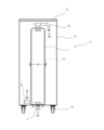
- FIG. 1 is a longitudinal sectional view showing a vessel of a reverse osmosis membrane module according to an embodiment of the present invention.
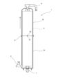
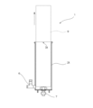
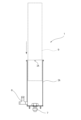
- FIG. 2 is a schematic diagram showing a water treatment apparatus in which a vessel of a reverse osmosis membrane module according to the embodiment is installed. It is a schematic diagram showing the removal process of the reverse osmosis membrane module in the vessel of the reverse osmosis membrane module according to the embodiment. It is a schematic diagram showing the removal process of the reverse osmosis membrane module in the vessel of the reverse osmosis membrane module according to the embodiment. It is a schematic diagram showing the installation process of the reverse osmosis membrane module in the vessel of the reverse osmosis membrane module according to the embodiment.
- FIG. 1 is a schematic diagram showing a water treatment apparatus in which a conventional reverse osmosis membrane module vessel is installed.
- FIG. 1 shows a vessel of a reverse osmosis membrane module according to one embodiment of the invention.
- the vessel 1 of this reverse osmosis membrane module is formed by joining a cylindrical lower member 2A and an upper member 2B, and the open end (joint part) of the lower member 2A and upper member 2B has a positioning hole. Markings 3A and 3B are attached, respectively.
- the lower member 2A and the upper member 2B are connected by a clamp 4 in a ferrule structure as a high-voltage connection structure, with an O-ring 5 interposed between their joint surfaces.
- a water supply member 6 to which a water supply pipe (not shown) is connected to the side is connected to the lower end of the lower member 2A, and a treated water outlet member 7 is connected to the lower part.
- a discharge member 8 to which a brine pipe (not shown) is connected is connected to the top of the upper member 2B.
- a reverse osmosis membrane module 9 is housed within this vessel 1.
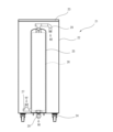
- FIG. 2 An example of a water treatment apparatus having a vessel 1 containing a reverse osmosis membrane module 9 as described above is schematically shown in FIG. 2 .
- the water treatment device 11 has a structure in which a vessel 1 is vertically arranged within a frame 12 having a top plate 13 and legs 14. Then, when a water supply pipe (not shown) is connected to the water supply member 6 of this vessel 1 and supply water (raw water) W is supplied, this raw water W is treated by the reverse osmosis membrane module 9 and then flows from the treated water outlet member 7. While discharging treated water (pure water) W1, concentrated water W2 is discharged from a discharge member 8 connected to a brine pipe (not shown).
- the vessel 1 of the reverse osmosis membrane module 9 of this embodiment as described above can be divided into the lower member 2A and the upper member 2B, so by removing the upper member 2B, the reverse osmosis membrane module 9 can be separated. Since the upper part is exposed, the reverse osmosis membrane module 9 can be easily extracted and replaced without having to remove the entire vessel.
- the dividing point between the lower member 2A and the upper member 2B is connected by a high pressure-resistant connection structure, watertightness can be maintained at the connecting point between the lower member 2A and the upper member 2B. , can be easily divided.
- the present invention has been described above based on the embodiments described above, the present invention is not limited to the embodiments described above, and various modifications can be made.
- the water treatment device 11 to which the vessel 1 is attached is not limited to the one shown in FIG. 2, but can be of various device configurations.
- the present invention can be similarly applied to water treatment apparatuses equipped with activated carbon cartridges, non-regenerating mixed bed ion exchange resin cartridges, and the like.
Landscapes
- Chemical & Material Sciences (AREA)
- Engineering & Computer Science (AREA)
- Water Supply & Treatment (AREA)
- Nanotechnology (AREA)
- Chemical Kinetics & Catalysis (AREA)
- Separation Using Semi-Permeable Membranes (AREA)
Abstract
逆浸透膜モジュールのベッセル1は、円筒状の下側部材2Aと上側部材2Bとからなり、下側部材2Aと上側部材2Bの開口端部には位置合わせ用のマーキング3A,3Bがそれぞれ付されている。この下側部材2Aと上側部材2Bとは、両者の接合面にOリング5を介在させて、クランプ4により高耐圧接続構造としてのヘルール構造で接続されている。下側部材2Aの下端には、側部に給水管が接続する給水部材6が接続されているとともに下部に処理水出口部材7が接続されている。また、上側部材2Bの頂部には、ブライン配管が接続する排出部材8が接続されている。そして、このベッセル1内に逆浸透膜モジュール9が収容されている。このような逆浸透膜モジュールのベッセルであれば、逆浸透膜モジュールの交換作業を容易にすることができる。
Description
本発明は、逆浸透膜モジュールを縦方向に設置して使用する水処理装置における逆浸透膜モジュールのベッセルに関する。
従来、医薬品、化粧品の製造、電子部品、精密機器の洗浄等においては、不純物を含まない高純度の純水が使用される。この種の純水を製造する装置として、純水製造装置等の水処理装置が用いられることがある。この水処理装置では、純水は、地下水、水道水等の原水を、逆浸透膜(RO膜)モジュールを備えた水処理装置で膜分離処理することにより製造することが汎用的に行われている。
この逆浸透膜(RO膜)モジュールを備えた水処理装置を図7に概略的に示す。図7において、水処理装置21は、天板23と脚部24とを備えた枠体22内に1個の逆浸透膜モジュール26を収容したベッセル25を縦方向に配置した構造を有する。そして、このベッセル25の給水部材27に給水管(図示せず)を接続して給水(原水)Wを供給すると、この原水Wは逆浸透膜モジュール26で処理されて、処理水(純水)W1を処理水出口部材28から吐出するとともに、濃縮水W2をブライン配管(図示せず)に接続した排出部材29から排出する。
この水処理装置1では逆浸透膜モジュール26は、原水Wの処理量や水質に応じて定期的(例えば2~3年/回)に交換している。
上述したような水処理装置21において、逆浸透膜モジュール26を交換する場合、ベッセル25が縦方向に設置されているので、天板23を開成してベッセル25の上部を開放し、排出部材29からブライン配管のジョイントを解除したら、ベッセル25ごと上側に引き抜くようにして水処理装置21から取り外し、このベッセル25を作業台にて横置した状態で固定し、排出部材29を含む頂部を外して、ベッセル25から逆浸透膜モジュール26を取り出して交換している。
しかしながら、ベッセル25は全長が100cmを超えることもあるため、ベッセル25を水処理装置21から引き抜くには、作業台などを使用して複数人で行わなければならない。さらに、逆浸透膜モジュール26を交換した後、再度水処理装置21内にベッセル25を縦方向に設置する必要があり、その交換作業の工程数が多く、煩雑で作業時間を要する、という問題点があった。
本発明は上記課題に鑑みてなされたものであり、逆浸透膜モジュールを縦方向に設置して使用する水処理装置における逆浸透膜モジュールの交換作業を容易にすることの可能な逆浸透膜モジュールのベッセルを提供することを目的とする。
上記目的を達成するために本発明は、逆浸透膜モジュールを長手方向から収容し、縦方向に設置される逆浸透膜モジュールのベッセルであって、該ベッセルが長手方向に分割可能となっている、逆浸透膜モジュールのベッセルを提供する(発明1)。
かかる発明(発明1)によれば、ベッセルを長手方向に分割可能とすることで、上側のベッセルを取り外すことで、逆浸透膜モジュールの上部が露出するので、ベッセルごと取り外す必要なく、逆浸透膜モジュールを抜き出すことができ、これにより逆浸透膜モジュールの交換作業を簡単に行うことができる。
上記発明(発明1)においては、前記逆浸透膜モジュールのベッセルの分割箇所が該逆浸透膜モジュールのベッセルの略中央であることが好ましい(発明2)。上記発明(発明2)においては、前記逆浸透膜モジュールを収容して縦方向に設置した逆浸透膜モジュールの上部を分割箇所から分離することで、前記逆浸透膜モジュールを前記ベッセルから取り出し可能となっていることが好ましい(発明3)。
かかる発明(発明2,3)によれば、ベッセルを長手方向に分割して上側のベッセルを取り外すと、逆浸透膜モジュールの略上半分が露出するので、ベッセルごと取り外す必要なく、逆浸透膜モジュールを抜き出すことができる。
また、上記発明(発明1,2)においては、前記逆浸透膜モジュールのベッセルの分割箇所が高耐圧接続構造により接続されていることが好ましい(発明4)。
かかる発明(発明4)によれば、ベッセルの分割箇所をヘルール構造などの高耐圧接続構造で接続することにより、分割箇所における水密性を維持しつつ、簡単に分割することができる。
本発明の逆浸透膜モジュールのベッセルは、略中央で長手方向に分割可能となっているので、上側のベッセルを取り外すことで、逆浸透膜モジュールの上部が露出するため、ベッセルごと取り外す必要なく、逆浸透膜モジュールを抜き出すことができる。このような逆浸透膜モジュールのベッセルを採用することにより、逆浸透膜モジュールの交換作業の作業を簡略化することができ、作業負荷の軽減及び作業時間の短縮を図ることができる。
以下、本発明の逆浸透膜モジュールのベッセルについて添付図面を参照して詳細に説明する。
<逆浸透膜モジュールのベッセル>
図1は、本発明の一実施形態による逆浸透膜モジュールのベッセルを示している。この逆浸透膜モジュールのベッセル1は、円筒状の下側部材2Aと上側部材2Bとを接合してなり、下側部材2Aと上側部材2Bの開口端部(接合部)には位置合わせ用のマーキング3A,3Bがそれぞれ付されている。この下側部材2Aと上側部材2Bとは、両者の接合面にOリング5を介在させて、クランプ4により高耐圧接続構造としてのヘルール構造で接続されている。
図1は、本発明の一実施形態による逆浸透膜モジュールのベッセルを示している。この逆浸透膜モジュールのベッセル1は、円筒状の下側部材2Aと上側部材2Bとを接合してなり、下側部材2Aと上側部材2Bの開口端部(接合部)には位置合わせ用のマーキング3A,3Bがそれぞれ付されている。この下側部材2Aと上側部材2Bとは、両者の接合面にOリング5を介在させて、クランプ4により高耐圧接続構造としてのヘルール構造で接続されている。
このようなベッセル1において、下側部材2Aの下端には、側部に給水管(図示せず)が接続する給水部材6が接続されているとともに下部に処理水出口部材7が接続されている。また、上側部材2Bの頂部には、ブライン配管(図示せず)が接続する排出部材8が接続されている。そして、このベッセル1内に逆浸透膜モジュール9が収容されている。
<水処理装置>
上述したような逆浸透膜モジュール9を内在したベッセル1を有する水処理装置の一例を図2に概略的に示す。図2において、水処理装置11は、天板13と脚部14とを備えた枠体12内にベッセル1を縦方向に配置した構造を有する。そして、このベッセル1の給水部材6に給水管(図示せず)を接続して給水(原水)Wを供給すると、この原水Wは逆浸透膜モジュール9で処理されて、処理水出口部材7から処理水(純水)W1を吐出するとともに、濃縮水W2をブライン配管(図示せず)が接続した排出部材8から排出する。
上述したような逆浸透膜モジュール9を内在したベッセル1を有する水処理装置の一例を図2に概略的に示す。図2において、水処理装置11は、天板13と脚部14とを備えた枠体12内にベッセル1を縦方向に配置した構造を有する。そして、このベッセル1の給水部材6に給水管(図示せず)を接続して給水(原水)Wを供給すると、この原水Wは逆浸透膜モジュール9で処理されて、処理水出口部材7から処理水(純水)W1を吐出するとともに、濃縮水W2をブライン配管(図示せず)が接続した排出部材8から排出する。
<逆浸透膜モジュールの交換方法>
このような水処理装置11の運転を継続して処理水量が増大すると次第に逆浸透膜モジュール9のろ過性能が低下するので、該逆浸透膜モジュール9を交換する必要が生じる。この際のベッセル1内に収容した逆浸透膜モジュール9の交換方法について以下説明する。
このような水処理装置11の運転を継続して処理水量が増大すると次第に逆浸透膜モジュール9のろ過性能が低下するので、該逆浸透膜モジュール9を交換する必要が生じる。この際のベッセル1内に収容した逆浸透膜モジュール9の交換方法について以下説明する。
(逆浸透膜モジュールの取り外し工程)
まず、図1に示すベッセル1の中央のクランプ4を取り外し、下側部材2Aと上側部材2Bとの接続を解除する(図3)。そして、排出部材8に接続しているブライン配管のジョイントを取り外す。次に水処理装置11の天板13を開成し、ベッセル1の上部空間を開放したら上側部材2Bを引き抜く。
まず、図1に示すベッセル1の中央のクランプ4を取り外し、下側部材2Aと上側部材2Bとの接続を解除する(図3)。そして、排出部材8に接続しているブライン配管のジョイントを取り外す。次に水処理装置11の天板13を開成し、ベッセル1の上部空間を開放したら上側部材2Bを引き抜く。
これにより図4に示すように逆浸透膜モジュール9の略上半分が露出するので、この逆浸透膜モジュール9を引き抜くことで取り外す。
(逆浸透膜モジュールの取り付け工程)
このようにして逆浸透膜モジュール9を取り外したら、図5に示すように交換用の逆浸透膜モジュール9を下側部材2Aに挿入する。この交換用の逆浸透膜モジュール9としては、新品の逆浸透膜モジュールや逆浸透膜モジュールを洗浄してろ過性能を回復させたリユース品などを用いることができる。
このようにして逆浸透膜モジュール9を取り外したら、図5に示すように交換用の逆浸透膜モジュール9を下側部材2Aに挿入する。この交換用の逆浸透膜モジュール9としては、新品の逆浸透膜モジュールや逆浸透膜モジュールを洗浄してろ過性能を回復させたリユース品などを用いることができる。
これにより逆浸透膜モジュール9の略上半分が露出した状態となるので、図6に示す様に下側部材2Aと上側部材2Bの位置合わせ用のマーキング3A,3Bの位置を確認しながら、上側部材2Bを被せる。そして、排出部材8にブライン配管の位置を合せ、下側部材2Aと上側部材2Bとをクランプ4により、ヘルール構造で接続する。最後に排出部材8とブライン配管とをジョイントにより接続することで、逆浸透膜モジュール9の取り付けを完了する。
上述したような本実施形態の逆浸透膜モジュール9のベッセル1は、下側部材2Aと上側部材2Bとに分割可能となっているので、上側部材2Bを取り外すことで、逆浸透膜モジュール9の上部が露出するので、ベッセルごと取り外す必要なく、逆浸透膜モジュール9を容易に抜き出して交換することが可能となっている。特に本実施形態においては、下側部材2Aと上側部材2Bとの分割箇所が高耐圧接続構造により接続されているので、下側部材2Aと上側部材2Bとの接続箇所における水密性を維持しつつ、簡単に分割することが可能となっている。
以上、本発明について前記実施形態に基づいて説明してきたが、本発明は前記実施形態に限定されず、種々の変形実施が可能である。例えば、ベッセル1を取り付ける水処理装置11としては、図2に示すものに限らず、種々の装置構成のものを用いることができきる。例えば、活性炭カートリッジや非再生式の混床式イオン交換樹脂カートリッジなどを備えた水処理装置についても同様に適用することができる。
1 逆浸透膜モジュールのベッセル
2A 下側部材
2B 上側部材
3A,3B 位置合わせ用マーキング
4 クランプ
5 Oリング
6 給水部材
7 処理水出口部材
8 排出部材
9 逆浸透膜モジュール
11 水処理装置
12 枠体
13 天板
14 脚部
W 給水(原水)
W1 処理水(純水)
W2 濃縮水
2A 下側部材
2B 上側部材
3A,3B 位置合わせ用マーキング
4 クランプ
5 Oリング
6 給水部材
7 処理水出口部材
8 排出部材
9 逆浸透膜モジュール
11 水処理装置
12 枠体
13 天板
14 脚部
W 給水(原水)
W1 処理水(純水)
W2 濃縮水
Claims (4)
- 逆浸透膜モジュールを長手方向から収容し、縦方向に設置される逆浸透膜モジュールのベッセルであって、
該ベッセルが長手方向に分割可能となっている、逆浸透膜モジュールのベッセル。 - 前記逆浸透膜モジュールのベッセルの分割箇所が該逆浸透膜モジュールのベッセルの略中央である、請求項1に記載の逆浸透膜モジュールのベッセル。
- 前記逆浸透膜モジュールを収容して縦方向に設置した逆浸透膜モジュールの上部を分割箇所から分離することで、前記逆浸透膜モジュールを前記ベッセルから取り出し可能となっている、請求項2に記載の逆浸透膜モジュールのベッセル。
- 前記逆浸透膜モジュールのベッセルの分割箇所が高耐圧接続構造により接続されている、請求項1又は2に記載の逆浸透膜モジュールのベッセル。
Applications Claiming Priority (2)
| Application Number | Priority Date | Filing Date | Title |
|---|---|---|---|
| JP2022-066208 | 2022-04-13 | ||
| JP2022066208A JP2023158662A (ja) | 2022-04-13 | 2022-04-13 | 逆浸透膜モジュールを収容したベッセルを備える水処理装置 |
Publications (1)
| Publication Number | Publication Date |
|---|---|
| WO2023199773A1 true WO2023199773A1 (ja) | 2023-10-19 |
Family
ID=88329559
Family Applications (1)
| Application Number | Title | Priority Date | Filing Date |
|---|---|---|---|
| PCT/JP2023/013785 Ceased WO2023199773A1 (ja) | 2022-04-13 | 2023-04-03 | 逆浸透膜モジュールのベッセル |
Country Status (3)
| Country | Link |
|---|---|
| JP (1) | JP2023158662A (ja) |
| TW (1) | TW202342156A (ja) |
| WO (1) | WO2023199773A1 (ja) |
Citations (5)
| Publication number | Priority date | Publication date | Assignee | Title |
|---|---|---|---|---|
| JPH0681621U (ja) * | 1993-04-24 | 1994-11-22 | 日東電工株式会社 | 液体分離装置 |
| JPH07163846A (ja) * | 1991-09-13 | 1995-06-27 | Dt Membranfilter Vertriebs Gmbh | 流動媒体を濾過し分離する容器を備える装置 |
| JPH11151431A (ja) * | 1997-09-16 | 1999-06-08 | Nikkiso Co Ltd | 濾過装置 |
| JP2003126661A (ja) * | 2001-10-26 | 2003-05-07 | Kurita Water Ind Ltd | 膜モジュールベッセル |
| JP2005224796A (ja) * | 2004-01-14 | 2005-08-25 | Toray Ind Inc | 中空糸膜モジュールおよびそれのカートリッジの交換方法 |
Family Cites Families (3)
| Publication number | Priority date | Publication date | Assignee | Title |
|---|---|---|---|---|
| JPS59184901U (ja) * | 1983-05-26 | 1984-12-08 | ダイセル化学工業株式会社 | 自緊式濾過装置 |
| JPH11216308A (ja) * | 1998-01-30 | 1999-08-10 | Orion Mach Co Ltd | フィルタ |
| JP3775084B2 (ja) * | 1998-12-16 | 2006-05-17 | 松下電器産業株式会社 | 浄水器 |
-
2022
- 2022-04-13 JP JP2022066208A patent/JP2023158662A/ja active Pending
-
2023
- 2023-04-03 WO PCT/JP2023/013785 patent/WO2023199773A1/ja not_active Ceased
- 2023-04-10 TW TW112113220A patent/TW202342156A/zh unknown
Patent Citations (5)
| Publication number | Priority date | Publication date | Assignee | Title |
|---|---|---|---|---|
| JPH07163846A (ja) * | 1991-09-13 | 1995-06-27 | Dt Membranfilter Vertriebs Gmbh | 流動媒体を濾過し分離する容器を備える装置 |
| JPH0681621U (ja) * | 1993-04-24 | 1994-11-22 | 日東電工株式会社 | 液体分離装置 |
| JPH11151431A (ja) * | 1997-09-16 | 1999-06-08 | Nikkiso Co Ltd | 濾過装置 |
| JP2003126661A (ja) * | 2001-10-26 | 2003-05-07 | Kurita Water Ind Ltd | 膜モジュールベッセル |
| JP2005224796A (ja) * | 2004-01-14 | 2005-08-25 | Toray Ind Inc | 中空糸膜モジュールおよびそれのカートリッジの交換方法 |
Also Published As
| Publication number | Publication date |
|---|---|
| TW202342156A (zh) | 2023-11-01 |
| JP2023158662A (ja) | 2023-10-31 |
Similar Documents
| Publication | Publication Date | Title |
|---|---|---|
| JPH0790219B2 (ja) | 純水製造装置及び製造方法 | |
| JP5597122B2 (ja) | 逆浸透処理装置 | |
| WO2015156242A1 (ja) | 膜を用いた水処理方法および水処理装置 | |
| DE102010043662B4 (de) | Brauereiabwasseraufbereitungsverfahren sowie Brauereiabwasseraufbereitungsvorrichtung | |
| WO2023199773A1 (ja) | 逆浸透膜モジュールのベッセル | |
| CN213596030U (zh) | 连续过滤膜浓缩装置 | |
| KR101906533B1 (ko) | 무기막 필터를 집수조에 이용한 산업 폐수(반도체 분야) 재이용 시스템 | |
| JP2014184438A (ja) | 逆浸透処理装置 | |
| RU2008152692A (ru) | Способ обработки оборотной воды | |
| JP6519889B1 (ja) | ろ過ユニットおよびこれを備えたプール水浄化装置 | |
| JP7105431B2 (ja) | 有機物含有排水の処理方法及び処理装置 | |
| JP7648345B2 (ja) | 純水製造方法及び製造装置 | |
| JP4180019B2 (ja) | 逆浸透膜の洗浄方法およびこの方法を用いた廃水回収方法 | |
| JP7547907B2 (ja) | フッ素含有排水の処理方法及び装置 | |
| JPH0957261A (ja) | 2段式逆浸透膜処理方法 | |
| WO2023026554A1 (ja) | フッ素含有水の処理方法及び装置 | |
| CN102264458A (zh) | 用于过滤的系统和方法 | |
| DE3335127A1 (de) | Verfahren zur abtrennung von quecksilber aus waessrigen fluessigkeiten | |
| KR102549174B1 (ko) | 한외여과막 모듈의 세정 방법 및 이를 이용한 초순수 제조 시스템의 관리 방법 | |
| JP6216847B2 (ja) | 逆浸透処理装置 | |
| KR20120033674A (ko) | 가압식 모듈을 이용한 여과 시스템 및 여과 방법 | |
| CN112437755A (zh) | 利用反渗透的废水再利用方法及装置 | |
| JP2005095812A (ja) | 水の浄水化装置および水の浄化方法 | |
| JPH09285787A (ja) | 超純水製造装置 | |
| JP2006212540A (ja) | 化学洗浄廃液の処理方法 |
Legal Events
| Date | Code | Title | Description |
|---|---|---|---|
| 121 | Ep: the epo has been informed by wipo that ep was designated in this application |
Ref document number: 23788193 Country of ref document: EP Kind code of ref document: A1 |
|
| NENP | Non-entry into the national phase |
Ref country code: DE |
|
| 122 | Ep: pct application non-entry in european phase |
Ref document number: 23788193 Country of ref document: EP Kind code of ref document: A1 |