WO2023199710A1 - 界磁子の製造方法 - Google Patents
界磁子の製造方法 Download PDFInfo
- Publication number
- WO2023199710A1 WO2023199710A1 PCT/JP2023/011175 JP2023011175W WO2023199710A1 WO 2023199710 A1 WO2023199710 A1 WO 2023199710A1 JP 2023011175 W JP2023011175 W JP 2023011175W WO 2023199710 A1 WO2023199710 A1 WO 2023199710A1
- Authority
- WO
- WIPO (PCT)
- Prior art keywords
- magnetization
- magnets
- magnetizing
- magnetized
- magnet
- Prior art date
- Legal status (The legal status is an assumption and is not a legal conclusion. Google has not performed a legal analysis and makes no representation as to the accuracy of the status listed.)
- Ceased
Links
Images



Classifications
-
- H—ELECTRICITY
- H02—GENERATION; CONVERSION OR DISTRIBUTION OF ELECTRIC POWER
- H02K—DYNAMO-ELECTRIC MACHINES
- H02K15/00—Processes or apparatus specially adapted for manufacturing, assembling, maintaining or repairing of dynamo-electric machines
- H02K15/02—Processes or apparatus specially adapted for manufacturing, assembling, maintaining or repairing of dynamo-electric machines of stator or rotor bodies
- H02K15/03—Processes or apparatus specially adapted for manufacturing, assembling, maintaining or repairing of dynamo-electric machines of stator or rotor bodies having permanent magnets
-
- H—ELECTRICITY
- H01—ELECTRIC ELEMENTS
- H01F—MAGNETS; INDUCTANCES; TRANSFORMERS; SELECTION OF MATERIALS FOR THEIR MAGNETIC PROPERTIES
- H01F13/00—Apparatus or processes for magnetising or demagnetising
- H01F13/003—Methods and devices for magnetising permanent magnets
-
- H—ELECTRICITY
- H02—GENERATION; CONVERSION OR DISTRIBUTION OF ELECTRIC POWER
- H02K—DYNAMO-ELECTRIC MACHINES
- H02K2215/00—Specific aspects not provided for in other groups of this subclass relating to methods or apparatus specially adapted for manufacturing, assembling, maintaining or repairing of dynamo-electric machines
Definitions
- the disclosure in this specification relates to a method for manufacturing a field element.
- each magnet is magnetized during manufacture.
- a method is known in which all magnets arranged circumferentially in a field element are magnetized at once (see Patent Document 1).
- the present disclosure has been made in view of the above circumstances, and an object of the present disclosure is to provide a method for manufacturing a field element that can appropriately magnetize each magnet of the field element.
- Means 1 is A method for manufacturing a field element having a plurality of magnets forming different magnetic poles in the circumferential direction, an assembling step of assembling the plurality of magnets before being magnetized to a magnetizing device in an annular arrangement; a first magnetization step in which a magnetization magnetic field is generated by the magnetization device, and all of the magnets arranged in an annular manner are magnetized by the magnetization magnetic field; After the first magnetization step, the magnetization device generates a magnetization magnetic field stronger than that in the first magnetization step, and the magnetization field causes a predetermined circumferential direction of all the magnets arranged in an annular shape to be generated. a second magnetization step of sequentially magnetizing each number of magnets; has.
- magnetization is performed in two stages. Specifically, in the first stage of magnetization, all the magnets arranged in an annular manner are magnetized by a magnetizing magnetic field generated by a magnetizing device (first magnetization step), and then in the second stage For magnetization, a magnetization device generates a stronger magnetization magnetic field than in the first magnetization step, and the magnetization field causes a predetermined number of magnets in the circumferential direction of all the magnets arranged in an annular shape to be magnetized. The magnetization was performed in order (second magnetization step).
- the entire circumference is magnetized using a relatively weak magnetizing magnetic field, and a counter magnetic flux corresponding to the leakage magnetic flux is formed in each magnet.
- leakage magnetic flux is generated due to the relatively strong magnetizing magnetic field, and there is a concern that the leakage flux will affect surrounding magnets with the same polarity as the magnet to be magnetized, but in the first stage of magnetization,
- the countermagnetic flux of the magnets formed by the magnets suppresses the influence of leakage magnetic flux. This suppresses variations in surface magnetic flux density in each magnet. As a result, each magnet of the field element can be properly magnetized.
- means 2 in means 1, in the first magnetization step, magnetization is performed with a magnetic field weaker than the saturation magnetization magnetic field that saturates the magnet, and in the second magnetization step, the magnet is Perform magnetization with .
- magnetization was performed with a magnetic field weaker than the saturation magnetization field
- magnetization was performed with a saturation magnetization field. This allows each magnet to be saturated and magnetized as desired.
- the magnetizing device includes: a magnetizing yoke arranged opposite to the field element; a plurality of magnetizing coils provided for each magnetic pole of the field element in the magnetizing yoke; a power supply section that supplies power to the plurality of magnetized coils; A first state in which power for forming a magnetizing magnetic field is supplied from the power supply unit to all of the plurality of magnetized coils, and a part of the plurality of magnetized coils is a switching unit that switches between a second state and a second state in which power for forming a magnetizing magnetic field is supplied from the power supply unit to the magnetic coil; In the first magnetization step, all the magnets are magnetized in the first state, In the second magnetization step, the second state is set, and the predetermined number of magnets are sequentially magnetized.
- the first magnetization step all the magnetized coils among the plurality of magnetized coils are set to a first state in which power is supplied from the power supply unit, and all the magnets are magnetized, while the second state is
- a part of the magnetization coils was set in a second state in which power was supplied from the power supply unit, and a predetermined number of magnets were sequentially magnetized.
- all magnets can be magnetized all around, and divided magnetization with a stronger magnetic field than that (magnetization of a predetermined number of magnets) ) can be carried out appropriately.
- the power supply unit includes a capacitor that supplies power for magnetization to the plurality of magnetized coils, and a charging unit that charges the capacitor, In the first magnetizing step, the capacitor is charged by the charging unit, and all the magnetizing coils are energized at the same time by discharging the capacitor, In the second magnetization step, each time the predetermined number of magnets are magnetized, the capacitor is charged by the charging unit, and the magnetized coil corresponding to each magnetized object is charged by discharging the capacitor. energize.
- the field element includes the plurality of magnets and a cylindrical magnet holding member that holds each of the magnets, and in the assembling step, the magnet holding member is attached to the magnetizing yoke.
- the plurality of magnets are assembled to the magnetizing device while the circumferential position of the member is regulated by the position regulating member.
- each magnet can be assembled at an appropriate position with respect to the magnetizing coil. Therefore, when performing divided magnetization, it is possible to properly magnetize the magnet that is the target of divided magnetization among all the magnets.
- the magnet thickness dimension D1 which is the radial thickness of the magnet, and the circumferential width dimension D2 of one magnetic pole are D1>D2 ⁇ 1/2.
- the magnet thickness dimension D1 which is the radial thickness of the magnet, and the circumferential width dimension D2 of one magnetic pole are D1>D2 ⁇ 1/2
- the magnet thickness dimension D1 is relatively large. It is conceivable that a strong magnetizing magnetic field is required to magnetize the magnet, resulting in strong leakage magnetic flux. Further, since the circumferential width dimension D2 of one magnetic pole is relatively small, the magnetic pole pitch becomes short, and the influence of leakage magnetic flux is considered to become large. For example, in a rotating electrical machine with a large number of poles or a high torque, there is a greater concern about problems caused by leakage magnetic flux. In this regard, by performing full-circle magnetization and split magnetization in two stages as described above, it is possible to achieve suitable magnetization even for field elements of rotating electric machines with a large number of poles or high torque. can.
- the magnet is a polar anisotropic magnet.
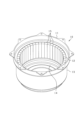
- FIG. 1 is a perspective view showing an overview of the rotor
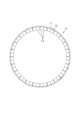
- FIG. 2 is a cross-sectional view of the rotor
- FIG. 3 is a diagram showing the orientation direction of the magnet
- FIG. 4 is a diagram showing a rotor and a magnetizing device
- FIG. 5 is a diagram showing the state of magnetic flux when performing split magnetization
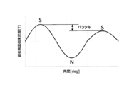
- FIG. 6 is a diagram showing the angular distribution of the magnet surface magnetic flux density
- FIG. 7 is a circuit diagram showing the electrical configuration of the magnetizing device
- FIG. 8 is a flowchart showing the procedure of the magnetization process
- FIG. 9 is a diagram showing the configuration of the position regulating member
- FIG. 10 (a) is a diagram for explaining full-circumference magnetization, and (b) is a diagram for explaining divided magnetization.
- the rotating electrical machine in this embodiment is used, for example, as a vehicle-mounted electric device.
- rotating electric machines can be widely used for industrial purposes, ships, aircraft, home appliances, OA equipment, game machines, and the like.
- the rotating electric machine is an outer rotor type surface magnet type multiphase AC motor, and as is well known, has a rotor as a field element and a stator as an armature.
- the rotor and stator are arranged to face each other in the radial direction, and the rotor is rotatable about the rotation axis with respect to the stator.
- the stator is, for example, a toothless stator in which stator windings are assembled on the radially outer side of a cylindrical stator core (back yoke).
- the stator may have a slot winding structure in which stator windings are wound around a plurality of slots provided in a stator core.
- FIG. 1 is a perspective view showing an overview of the rotor 10
- FIG. 2 is a cross-sectional view of the rotor 10.
- the rotor 10 has a substantially cylindrical rotor carrier 11 and an annular magnet unit 12 fixed to the rotor carrier 11.
- the rotor carrier 11 is made of, for example, a magnetic material, and has a cylindrical cylindrical portion 13 and an end plate portion 14 provided at one end in the axial direction of the cylindrical portion 13 .
- a magnet unit 12 is fixed inside the cylindrical portion 13 in the radial direction.
- the other end of the rotor carrier 11 in the axial direction is open.
- the rotor carrier 11 functions as a magnet holding member.
- the magnet unit 12 is composed of a plurality of magnets 15 arranged so that the polarity alternates along the circumferential direction of the rotor 10. Thereby, the magnet unit 12 has a plurality of magnetic poles in the circumferential direction.
- the magnet 15 is, for example, a sintered neodymium magnet having an intrinsic coercive force of 400 [kA/m] or more and a residual magnetic flux density Br of 1.0 [T] or more.
- Each magnet 15 of the magnet unit 12 is a polar anisotropic permanent magnet. As shown in FIG. 3, the magnet 15 has a different axis of easy magnetization between the d-axis side (portion closer to the d-axis), which is the center of the magnetic pole, and the q-axis side (portion closer to the q-axis), which is the magnetic pole boundary. However, on the d-axis side, the easy magnetization axis is parallel to the d-axis, and on the q-axis side, the easy magnetization axis is perpendicular to the q-axis. In this case, an arcuate magnet magnetic path is formed along the direction of the axis of easy magnetization.
- each magnet 15 is oriented such that on the d-axis side, which is the center of the magnetic pole, the axis of easy magnetization is more parallel to the d-axis than on the q-axis side, which is the magnetic pole boundary. .
- the magnet unit 12 has two magnets 15 for each magnetic pole, and the magnets 15 are provided with their circumferential side surfaces in contact with each other.
- the magnet 15 for one magnetic pole that is, two magnets 15 of the same polarity arranged in the circumferential direction, is also referred to as a magnetic pole magnet 16.
- the magnet unit 12 may have one magnet 15 for each magnetic pole.
- This embodiment is characterized by the method of manufacturing the magnet unit 12, and the manufacturing method will be described below.
- the magnet unit 12 When manufacturing the magnet unit 12, first, purified raw materials such as neodymium, boron, and iron are melted and alloyed (melting process). Next, the alloy obtained in the melting process is crushed into particles (pulverization process). Then, the powder obtained in the pulverization process is put into a mold and pressure-molded in a magnetic field (molding process). By molding with this mold, the magnet 15 is molded into a predetermined shape. Further, in this step, the axis of easy magnetization is oriented in the magnet 15 in, for example, an arc shape, as described above.
- the molded product After being pressure-molded, the molded product is sintered (sintering process), and after sintering, it is heat treated (heat treatment process). In the heat treatment, heating and cooling are performed several times. Then, mechanical processing such as grinding and surface processing are performed (processing process). Thereafter, the magnet 15 is completed by being magnetized (magnetization step).
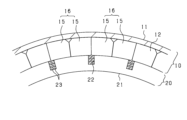
- FIG. 4 is a diagram showing the rotor 10 and the magnetizing device 20 assembled to the rotor 10.
- the magnetizing device 20 is a device that magnetizes the magnets 15 of each magnetic pole using an electromagnet, and includes a magnetizing yoke 21 having an annular shape and having a plurality of slots 22 inside in the radial direction, and a plurality of magnets accommodated in each slot 22.
- a magnetizing coil 23 is provided.
- the slots 22 are provided in the same number and at the same pitch as the number of magnetic poles of the rotor 10.
- the magnetizing coil 23 is provided for each magnetic pole of the rotor 10, and is constructed by winding a conducting wire a plurality of times between circumferentially adjacent slots 22.
- the rotor 10 is arranged radially outward of the magnetizing yoke 21. At this time, the rotor 10 is arranged so that the magnetic pole center (d-axis) of the rotor 10 and the circumferential center position of the slot 22 of the magnetizing yoke 21 coincide with each other.
- a magnetizing magnetic field is generated for each magnetic pole of the rotor 10 as a current flows through each magnetizing coil 23 as a result of energization by a power supply section, which will be described later. This magnetizing magnetic flux magnetizes each magnet 15, and magnetic poles of different polarities are formed alternately in the circumferential direction in the rotor 10.
- each magnet 15 of the magnet unit 12 all the magnets 15 of the rotor 10 are divided into a plurality of magnets 15 in the circumferential direction, and each of the plurality of magnets 15 is A possible method is to perform magnetization by the magnetization device 20 in order. In this method, based on the magnetic poles, a predetermined number of magnetic poles (pole magnets 16) out of all the magnetic poles (pole magnets 16) of the rotor 10 are sequentially magnetized by the magnetizing device 20. It is a method.
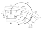
- FIG. 5 is a diagram showing a state when performing divided magnetization.
- FIG. 5 shows three magnetic pole magnets 16A, 16B, and 16C, of which two magnetic pole magnets 16A and 16B are magnetized. Note that although the magnetizing device 20 is shown in a different form from that in FIG. 4 in FIG. 5, it has substantially the same configuration.
- the magnet thickness dimension D1 which is the radial thickness of the magnet 15, and the circumferential width dimension D2 of one magnetic pole (width dimension of the magnetic pole magnet 16) are such that D1>D2 ⁇ 1/2
- a possible configuration is as follows.
- the width dimension D2 is, for example, the width dimension at the radial center position of the magnetic pole magnet 16, or the width dimension at the radially inner end portion or the radially inner end portion of the magnetic pole magnet 16.
- the magnet thickness dimension D1 is relatively large, a strong magnetizing magnetic field is required to magnetize the magnet 15, and it is conceivable that a strong leakage magnetic flux Fa is generated.
- the width dimension D2 of one magnetic pole in the circumferential direction is relatively small, the magnetic pole pitch becomes short, and the influence of the leakage magnetic flux Fa becomes large. For example, in a rotating electrical machine with a large number of poles or a high torque, there is a great concern that problems due to leakage magnetic flux Fa may occur.
- magnetization when manufacturing the rotor 10, magnetization is performed in two stages. Specifically, as the first stage of magnetization, all the magnets 15 arranged in an annular manner are magnetized by the magnetizing magnetic field generated by the magnetizing device 20 (first magnetization step), and then the second magnetization step is performed. As the magnetization step, the magnetization device 20 generates a magnetization magnetic field stronger than that in the first magnetization step, and the magnetization field causes a predetermined number of magnets in the circumferential direction of all the magnets 15 arranged in an annular shape to be generated. The magnets 15 are sequentially magnetized (second magnetization step). The details will be explained below.
- FIG. 7 is a circuit diagram showing the electrical configuration of the magnetizing device 20.
- the magnetizing device 20 includes an AC power supply 31, a charging circuit 32, a booster circuit 33, a rectifier circuit 34, a capacitor 35, a first switch 36, and a plurality of second switches 37. , and a control device 40.
- a booster circuit 33 is connected to the AC power source 31 via a charging circuit 32, and the charging circuit 32 switches between a state in which AC power is output from the AC power source 31 to the booster circuit 33 and a state in which it is not output.
- the AC power source 31 may be an external power source.
- a rectifier circuit 34 is connected to the booster circuit 33 .
- the booster circuit 33 boosts the voltage of the AC power supplied from the AC power supply 31 and outputs it to the rectifier circuit 34 .
- a capacitor 35 is connected to the rectifier circuit 34 .
- the rectifier circuit 34 converts the AC power input from the booster circuit 33 into DC power, and charges the capacitor 35 .
- the capacitor 35 is charged to a voltage of several thousand volts, for example.
- the plurality of magnetizing coils 23 are connected in series, and a capacitor 35 is connected in parallel to the plurality of magnetizing coils 23. Each magnetizing coil 23 is energized by the discharge of the capacitor 35.
- a first switch 36 is provided in the electrical path between the capacitor 35 and the magnetizing coil 23 to switch between energization and de-energization of the electrical path. Further, short circuit paths are provided at both ends of each magnetized coil 23, and a second switch 37 is provided in each of these short circuit paths.
- the capacitor 35 corresponds to a power supply section that supplies power to each magnetized coil 23.
- the AC power supply 31, the charging circuit 32, the booster circuit 33, and the rectifier circuit 34 correspond to a charging section that charges the capacitor 35.
- the control device 40 operates the charging circuit 32 to switch between a state in which AC power is output from the AC power supply 31 to the booster circuit 33 and a state in which it is not output. In this case, the capacitor 35 is charged by outputting AC power from the AC power supply 31 to the booster circuit 33. Further, the control device 40 controls on/off of each switch 36 and 37. In this case, the first switch 36 is turned on and at least one or more second switches 37 are maintained in the off state, so that the predetermined magnetized coil 23 is energized from the capacitor 35 .
- the control device 40 when performing full-circumference magnetization, the control device 40 turns on the first switch 36 and turns off all the second switches 37. As a result, all the magnetized coils 23 are energized (corresponding to the first state).
- the control device 40 when performing divided magnetization, turns on the first switch 36 and turns on only some of the second switches 37 among all the second switches 37. As a result, some of the magnetized coils 23 out of all the magnetized coils 23 are energized (corresponding to the second state). Specifically, for example, when energizing only the magnetizing coil 23A among all the magnetizing coils 23 in FIG. Turn off only the second switch 37 corresponding to , and turn on all the other second switches 37 . As a result, only the magnetizing coil 23A is energized.
- the control device 40 corresponds to a switching unit that switches between a first state and a second state.
- all the magnetizing coils 23 are divided into two pairs of circumferentially adjacent magnetizing coils 23, and the magnetizing coils 23 are sequentially magnetized.
- the second switch 37 may be provided for each two magnetizing coils 23. Note that the number of magnetized coils 23 to be magnetized once in the divided magnetization is at least one or more, and preferably 1/2 of the total number.
- the charging power of the capacitor 35 is supplied to all the magnetizing coils 23, whereas when performing split magnetization, the charging power of the capacitor 35 is supplied to all the magnetizing coils 23. It is supplied only to a specific magnetizing coil 23 among the magnetizing coils 23. Therefore, when full-circumference magnetization is performed, the voltage applied to each magnetizing coil 23 is relatively low, and each magnet 15 is magnetized with a relatively weak magnetic field. On the other hand, when performing divided magnetization, the voltage applied to each magnetizing coil 23 becomes relatively high, and each magnet 15 is magnetized with a relatively strong magnetic field.
- FIG. 8 is a flowchart showing detailed steps in the magnetization process.
- Step S11 When magnetizing each magnet 15, first, the rotor 10 with the magnets 15 not yet magnetized is assembled into the magnetizing device 20 (step S11). As a result, the magnets 15 before being magnetized are assembled to the magnetizing device 20 in a ring-shaped arrangement.
- Each magnet 15 is a magnet whose axis of easy magnetization is already oriented, as described above. At this time, each magnet 15 is arranged so that the q axis faces the slot 22.
- Step S11 corresponds to an assembly process.
- each magnet 15 is preferably assembled to the magnetizing device 20 while the circumferential position of the rotor carrier 11 relative to the magnetizing yoke 21 is regulated.
- FIG. 9 is a diagram showing a specific configuration for regulating the position of the rotor carrier 11.
- 9(a) is a cross-sectional view of the rotor 10 and the magnetizing device 20, and
- FIG. 9(b) is a cross-sectional view taken along the line 9B-9B in FIG. 9(a).
- the magnetizing yoke 21 is disposed on the opposite side (radially inner side) of the rotor carrier 11 with respect to the magnets 15 of the rotor 10, and in this state, , the axial end portion of the magnetizing yoke 21 and the end plate portion 14 of the rotor carrier 11 are opposed to each other. Further, the magnetizing yoke 21 is provided with a columnar engaging portion 25 extending in the axial direction, and the engaging portion 25 is connected to the positioning hole 14a provided in the end plate portion 14 of the rotor carrier 11. The circumferential position of the rotor carrier 11 with respect to the magnetizing yoke 21 is regulated by being inserted into the magnetizing yoke 21 . Note that the engaging portion 25 corresponds to a position regulating member.
- FIG. 10(a) is a diagram illustrating full-circumference magnetization.
- a weak magnetizing magnetic field is generated by weakly energizing all the magnetizing coils 23 of the magnetizing device 20, and the magnetizing magnetic field creates a ring shape. All the magnets 15 in a row are magnetized.
- Step S12 corresponds to the first magnetization step.
- the capacitor 35 is charged with the output of AC power from the AC power source 31, and all the magnetized coils 23 are energized at the same time by discharging the capacitor 35.
- full-circumference magnetization is performed using a relatively weak magnetizing magnetic field.
- magnetization is performed using a magnetic field weaker than the saturation magnetization magnetic field that magnetizes the magnet 15 to saturation.
- FIG. 10(b) is a diagram illustrating divided magnetization.
- two magnetic pole magnets 16A and 16B are magnetized each time, and a strong magnetizing magnetic field is applied by strongly energizing the two magnetizing coils 23. This causes each magnetic pole magnet 16A, 16B to be magnetized.
- a predetermined number of magnets 15 are sequentially magnetized. Step S13 corresponds to the second magnetization step.
- the capacitor 35 is charged with the output of AC power from the AC power supply 31, and the capacitor 35 is discharged, so that the magnets 15 corresponding to the two magnetic poles are The two magnetizing coils 23 are energized.
- divided magnetization is performed using a relatively strong magnetizing magnetic field.
- magnetization is performed with a saturated magnetization magnetic field. Note that the magnetic field that magnetizes the magnet 15 with a magnetization rate of 100% is defined as a saturation magnetization magnetic field.
- step S14 the rotor 10 is taken out from the magnetization device 20 (step S14). This completes the series of magnetization steps.
- each magnet 15 of the rotor 10 When magnetizing the magnets 15 of the rotor 10, by performing full-circle magnetization and divided magnetization as described above, variations in the surface magnetic flux density of each magnet 15 are suppressed. As a result, each magnet 15 of the rotor 10 can be properly magnetized. Moreover, by suppressing variations in the surface magnetic flux density of each magnet 15, it is possible to output high torque in the rotating electric machine, and it is also possible to suppress vibrations and noise caused by variations in the surface magnetic flux density.
- first magnetization process magnetization is performed with a magnetic field weaker than the saturation magnetization magnetic field
- second magnetization process magnetization is performed with a saturation magnetization magnetic field. did. This allows each magnet 15 to be saturated and magnetized as desired.
- all the magnetizing coils 23 of the magnetizing device 20 are set to the first state in which power is supplied from the power supply unit, and all the magnets 15 are magnetized, while the divided magnetization is Now, a second state is set in which power is supplied from the power supply unit to some of the magnetizing coils 23, and a predetermined number of magnets 15 are sequentially magnetized. In this case, by distributing power to each magnetizing coil 23 by the power supply unit, all the magnets 15 are magnetized all around, and divided magnetization with a stronger magnetic field than the whole circumference magnetization (a predetermined number of magnets 15 magnetization) can be performed appropriately.
- each magnet 15 can be assembled to the magnetizing coil 23 at an appropriate position. Thereby, when performing divided magnetization, it is possible to properly magnetize the magnet 15 that is the target of divided magnetization among all the magnets 15.
- the influence of the leakage magnetic flux Fa may become large. Conceivable. For example, in a rotating electrical machine with a large number of poles or a high torque, there is a great concern that problems due to leakage magnetic flux Fa may occur. In this regard, by performing full-circle magnetization and divided magnetization in two stages as described above, it is possible to achieve suitable magnetization even for the rotor 10 of a rotating electrical machine with a large number of poles or a high torque. can.
- the magnet unit 12 has a structure in which the magnet 15 is divided into at least one magnetic pole.
- a structure using a magnet may also be used.
- the magnet 15 is not limited to one in which an arc-shaped magnet magnetic path is formed, but may be one in which a linear magnet magnetic path extending in the radial direction is formed.
- a surface magnet type rotor is used as the rotor 10, but instead of this, a structure may be adopted in which an embedded magnet type rotor is used.
- the rotating electrical machine has an outer rotor structure, but this may be changed to a rotating electrical machine having an inner rotor structure.
- a stator is provided on the outside in the radial direction, and a rotor is provided on the inside in the radial direction.
- ⁇ A a rotating electrical machine, instead of a rotating field type rotating electrical machine where the field element is the rotor and the armature is the stator, a rotating armature type rotating machine where the armature is the rotor and the field element is the stator. It is also possible to use electric equipment.
- the disclosure in this specification is not limited to the illustrated embodiments.
- the disclosure includes the illustrated embodiments and variations thereon by those skilled in the art.
- the disclosure is not limited to the combinations of parts and/or elements illustrated in the embodiments.
- the disclosure can be implemented in various combinations.
- the disclosure may have additional parts that can be added to the embodiments.
- the disclosure includes those in which parts and/or elements of the embodiments are omitted.
- the disclosure encompasses any substitutions or combinations of parts and/or elements between one embodiment and other embodiments.
- the disclosed technical scope is not limited to the description of the embodiments.
- the technical scope of some of the disclosed technical scopes is indicated by the description of the claims, and should be understood to include equivalent meanings and all changes within the scope of the claims.
- a method for manufacturing a field element comprising: [Configuration 2] In the first magnetization step, magnetization is performed with a magnetic field weaker than a saturation magnetization magnetic field that magnetizes the magnet to saturation, The method for manufacturing a field element according to Configuration 1, wherein in the second magnetization step, magnetization is performed using the saturation magnetization magnetic field.
- the magnetizing device includes: a magnetizing yoke (21) arranged opposite to the field element; a plurality of magnetizing coils (23) provided for each magnetic pole of the field element in the magnetizing yoke; a power supply unit (35) that supplies power to the plurality of magnetized coils; A first state in which power for forming a magnetizing magnetic field is supplied from the power supply unit to all of the plurality of magnetized coils, and a part of the plurality of magnetized coils is a switching unit (40) for switching between a second state in which power is supplied from the power supply unit to the magnetic coil for forming a magnetizing magnetic field; In the first magnetization step, all the magnets are magnetized in the first state, The method for manufacturing a field element according to configuration 1 or 2, wherein in the second magnetization step, the predetermined number of magnets are sequentially magnetized in the second state.
- the power supply unit includes a capacitor (35) that supplies power for magnetization to the plurality of magnetized coils, and a charging unit (31 to 34) that charges the capacitor,
- the capacitor In the first magnetizing step, the capacitor is charged by the charging unit, and all the magnetizing coils are energized at the same time by discharging the capacitor,
- the second magnetization step each time the predetermined number of magnets are magnetized, the capacitor is charged by the charging unit, and the magnetized coil corresponding to each magnetized object is charged by discharging the capacitor.
- the field element includes the plurality of magnets and a cylindrical magnet holding member (11) that holds each of the magnets, According to configuration 3 or 4, in the assembling step, the plurality of magnets are assembled to the magnetizing device while the circumferential position of the magnet holding member with respect to the magnetizing yoke is regulated by a position regulating member (25).
- Method for manufacturing field elements [Configuration 6] The field element according to any one of configurations 1 to 5, wherein the magnet thickness dimension D1, which is the radial thickness of the magnet, and the circumferential width dimension D2 of one magnetic pole satisfy D1>D2. Production method.
- Configuration 7 7. The method for manufacturing a field element according to any one of configurations 1 to 6, wherein the magnet is a polar anisotropic magnet.
Landscapes
- Engineering & Computer Science (AREA)
- Power Engineering (AREA)
- Manufacturing & Machinery (AREA)
- Permanent Field Magnets Of Synchronous Machinery (AREA)
Abstract
界磁子(10)は、周方向に異なる磁極を形成する複数の磁石(15)を有する。界磁子の製造方法は、着磁前の前記複数の磁石を、円環状に並ぶ状態で着磁装置(20)に組み付ける組み付け工程と、前記着磁装置により着磁磁界を生じさせ、その着磁磁界により、円環状に並ぶ全ての前記磁石に対して着磁を行う第1着磁工程と、前記第1着磁工程の後に、前記着磁装置により前記第1着磁工程よりも強い着磁磁界を生じさせ、その着磁磁界により、円環状に並ぶ全ての前記磁石のうち周方向の所定個数ずつの磁石に対して順番に着磁を行う第2着磁工程と、を有する。
Description
本出願は、2022年4月14日に出願された日本出願番号2022-067212号に基づくもので、ここにその記載内容を援用する。
この明細書における開示は、界磁子の製造方法に関する。
回転電機において、周方向に異なる磁極を形成するための複数の磁石を有する界磁子では、その製造時に各磁石に対する着磁が行われる。例えば、界磁子において周方向に並んだ状態で配置される全ての磁石に対して一括で着磁を行う手法が知られている(特許文献1参照)。
界磁子の各磁石を着磁する手法としては、上述した一括の着磁以外に、周方向に並ぶ全ての磁石を複数個ずつに分け、その複数個ずつの磁石ごとに着磁を行うことが考えられる。しかしながら、全ての磁石を複数に分けて着磁を行う場合において、着磁対象となる磁石を含む着磁エリアから漏れ磁束が発生すると、着磁エリア外の磁石が意図しない方向に着磁されてしまい、各磁石において表面磁束密度のバラツキが生じることが懸念される。
本開示は、上記事情に鑑みてなされたものであり、界磁子の各磁石を適正に着磁させることのできる界磁子の製造方法を提供することを目的とする。
この明細書における開示された複数の態様は、それぞれの目的を達成するために、互いに異なる技術的手段を採用する。この明細書に開示される目的、特徴、および効果は、後続の詳細な説明、および添付の図面を参照することによってより明確になる。
手段1は、
周方向に異なる磁極を形成する複数の磁石を有する界磁子の製造方法であって、
着磁前の前記複数の磁石を、円環状に並ぶ状態で着磁装置に組み付ける組み付け工程と、
前記着磁装置により着磁磁界を生じさせ、その着磁磁界により、円環状に並ぶ全ての前記磁石に対して着磁を行う第1着磁工程と、
前記第1着磁工程の後に、前記着磁装置により前記第1着磁工程よりも強い着磁磁界を生じさせ、その着磁磁界により、円環状に並ぶ全ての前記磁石のうち周方向の所定個数ずつの磁石に対して順番に着磁を行う第2着磁工程と、
を有する。
周方向に異なる磁極を形成する複数の磁石を有する界磁子の製造方法であって、
着磁前の前記複数の磁石を、円環状に並ぶ状態で着磁装置に組み付ける組み付け工程と、
前記着磁装置により着磁磁界を生じさせ、その着磁磁界により、円環状に並ぶ全ての前記磁石に対して着磁を行う第1着磁工程と、
前記第1着磁工程の後に、前記着磁装置により前記第1着磁工程よりも強い着磁磁界を生じさせ、その着磁磁界により、円環状に並ぶ全ての前記磁石のうち周方向の所定個数ずつの磁石に対して順番に着磁を行う第2着磁工程と、
を有する。
磁極ごとに設けられる複数の磁石を有する界磁子においてそれら各磁石の着磁を行う場合に、全ての磁石を所定個数ずつで複数に分け、それら所定個数ずつで磁石の着磁を行うことにより、着磁設備の簡略化が可能となる。ただし、所定個数ずつで磁石の着磁を行う場合には、着磁対象の磁石以外に対する漏れ磁束に起因して、各磁石において表面磁束密度のバラツキが生じることが懸念される。
この点、本製造方法では、2段階で着磁を行うこととした。具体的には、1段階目の着磁として、着磁装置により生じる着磁磁界により、円環状に並ぶ全ての磁石に対して着磁を行い(第1着磁工程)、その後、2段階目の着磁として、着磁装置により第1着磁工程よりも強い着磁磁界を生じさせ、その着磁磁界により、円環状に並ぶ全ての磁石のうち周方向の所定個数ずつの磁石に対して順番に着磁を行うようにした(第2着磁工程)。この場合、1段階目の着磁では、比較的弱い着磁磁界により全周着磁が行われ、各磁石に、漏れ磁束に対応する対抗磁束が形成される。また、2段階目の着磁では、比較的強い着磁磁界により漏れ磁束が生じ、着磁対象の磁石と同極の周辺磁石において漏れ磁束による影響が懸念されるが、1段階目の着磁で形成された磁石の対抗磁束により、漏れ磁束による影響が抑制される。これにより、各磁石において表面磁束密度のバラツキが抑制される。その結果、界磁子の各磁石を適正に着磁させることができる。
手段2では、手段1において、前記第1着磁工程では、前記磁石を飽和着磁させる飽和着磁磁界よりも弱い磁界で着磁を行い、前記第2着磁工程では、前記飽和着磁磁界で着磁を行う。
第1着磁工程では、飽和着磁磁界よりも弱い磁界で着磁を行い、第2着磁工程では、飽和着磁磁界で着磁を行うようにした。これにより、各磁石を所望のとおり飽和着磁の状態にすることができる。
手段3では、手段1又は2において、
前記着磁装置は、
前記界磁子に対して対向配置される着磁ヨークと、
前記着磁ヨークにおいて前記界磁子の磁極ごとに設けられる複数の着磁コイルと、
前記複数の着磁コイルに対して電力を供給する電力供給部と、
前記複数の着磁コイルのうち全ての着磁コイルに対して、前記電力供給部から着磁磁界形成のための電力を供給する第1状態と、前記複数の着磁コイルのうち一部の着磁コイルに対して、前記電力供給部から着磁磁界形成のための電力を供給する第2状態とを切り替える切替部と、を有し、
前記第1着磁工程では、前記第1状態とし、全ての前記磁石に対して着磁を行い、
前記第2着磁工程では、前記第2状態とし、前記所定個数ずつの磁石に対して順番に着磁を行う。
前記着磁装置は、
前記界磁子に対して対向配置される着磁ヨークと、
前記着磁ヨークにおいて前記界磁子の磁極ごとに設けられる複数の着磁コイルと、
前記複数の着磁コイルに対して電力を供給する電力供給部と、
前記複数の着磁コイルのうち全ての着磁コイルに対して、前記電力供給部から着磁磁界形成のための電力を供給する第1状態と、前記複数の着磁コイルのうち一部の着磁コイルに対して、前記電力供給部から着磁磁界形成のための電力を供給する第2状態とを切り替える切替部と、を有し、
前記第1着磁工程では、前記第1状態とし、全ての前記磁石に対して着磁を行い、
前記第2着磁工程では、前記第2状態とし、前記所定個数ずつの磁石に対して順番に着磁を行う。
第1着磁工程では、複数の着磁コイルのうち全ての着磁コイルに対して電力供給部から電力を供給する第1状態にして、全ての磁石に対して着磁を行う一方、第2着磁工程では、一部の着磁コイルに対して電力供給部から電力を供給する第2状態にして、所定個数ずつの磁石に対して順番に着磁を行うようにした。この場合、電力供給部による各着磁コイルへの電力の振り分けにより、全ての磁石に対する全周着磁と、その全周着磁よりも強磁界の分割着磁(所定個数ずつの磁石に対する着磁)とを適正に行わせることができる。
手段4では、手段3において、
前記電力供給部は、前記複数の着磁コイルに対して着磁のための電力を供給するコンデンサと、前記コンデンサに対する充電を行う充電部とを有し、
前記第1着磁工程では、前記充電部により前記コンデンサを充電するとともに、当該コンデンサの放電により全ての前記着磁コイルに対して同時期に通電を行い、
前記第2着磁工程では、前記所定個数ずつの磁石に対する着磁ごとに、前記充電部により前記コンデンサを充電するとともに、当該コンデンサの放電により都度の着磁対象に対応する前記着磁コイルに対して通電を行う。
前記電力供給部は、前記複数の着磁コイルに対して着磁のための電力を供給するコンデンサと、前記コンデンサに対する充電を行う充電部とを有し、
前記第1着磁工程では、前記充電部により前記コンデンサを充電するとともに、当該コンデンサの放電により全ての前記着磁コイルに対して同時期に通電を行い、
前記第2着磁工程では、前記所定個数ずつの磁石に対する着磁ごとに、前記充電部により前記コンデンサを充電するとともに、当該コンデンサの放電により都度の着磁対象に対応する前記着磁コイルに対して通電を行う。
全ての磁石に対する全周着磁では、充電後のコンデンサの放電により、全ての着磁コイルに対して同時期に通電が行われる一方、所定個数ずつの磁石に対する分割着磁では、充電後のコンデンサの放電により、都度の着磁対象(所定個数ずつの磁石)に対応する一部の着磁コイルに対して通電が行われる。これにより、分割着磁において、全周着磁よりも強磁界の着磁を好適に実施することができる。つまり、共通のコンデンサを用いつつも、比較的多数の着磁コイルに対する低電力の通電と、比較的少数の着磁コイルに対する高電力の通電とを好適に実施することができる。そのため、全ての着磁コイルに対して高電力の通電を行う場合に比べて、コンデンサ容量を低くすることができ、着磁設備の簡素化が可能となる。
手段5では、手段3において、前記界磁子は、前記複数の磁石と、それら各磁石を保持する円筒状の磁石保持部材とを有し、前記組み付け工程では、前記着磁ヨークに対する前記磁石保持部材の周方向位置を位置規制部材により規制した状態で、前記複数の磁石を前記着磁装置に組み付ける。
着磁ヨークに対する磁石保持部材の周方向位置を位置規制部材により規制するようにしたため、着磁コイルに対して各磁石を適正位置に組み付けることができる。これにより、分割着磁を行う際において、全ての磁石のうち分割着磁の対象である磁石に対して適正に着磁を行わせることができる。
手段6では、手段1において、前記磁石の径方向の厚みである磁石厚さ寸法D1と、1磁極の周方向の幅寸法D2とは、D1>D2×1/2である。
磁石の径方向の厚みである磁石厚さ寸法D1と、1磁極の周方向の幅寸法D2とが、D1>D2×1/2である構成では、磁石厚さ寸法D1が比較的大きいことにより、磁石の着磁に際して強い着磁磁界を要し、強い漏れ磁束が生じることが考えられる。また、1磁極の周方向の幅寸法D2が比較的小さいことにより、磁極ピッチが短くなり、漏れ磁束の影響が大きくなることが考えられる。例えば極数が多い又は高トルクの回転電機では、漏れ磁束による不都合の懸念が大きくなる。この点、上記のとおり全周着磁と分割着磁とを2段階で行うことにより、極数が多い又は高トルクの回転電機の界磁子であっても好適なる着磁を実現することができる。
手段7では、手段1において、前記磁石は、極異方性磁石である。
磁石において極異方性配向が行われている場合には、分割着磁を行う際において漏れ磁束による磁石磁束密度のバラツキの懸念が大きくなる。この点、上記のとおり全周着磁と分割着磁とを2段階で行うことにより、極異方性磁石を用いる界磁子であっても好適なる着磁を実現することができる。
本開示についての上記目的およびその他の目的、特徴や利点は、添付の図面を参照しながら下記の詳細な記述により、より明確になる。その図面は、
図1は、回転子の概要を示す斜視図であり、
図2は、回転子の横断面図であり、
図3は、磁石の配向方向を示す図であり、
図4は、回転子と着磁装置とを示す図であり、
図5は、分割着磁を行う場合の磁束の状態を示す図であり、
図6は、磁石表面磁束密度の角度分布を示す図であり、
図7は、着磁装置における電気的な構成を示す回路図であり、
図8は、着磁工程の手順を示すフローチャートであり、
図9は、位置規制部材の構成を示す図であり、
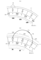
図10は、(a)は全周着磁を説明するための図、(b)は分割着磁を説明するための図である。
以下、実施形態を図面に基づいて説明する。本実施形態における回転電機は、例えば車載の電動装置として用いられるものとなっている。ただし、回転電機は、産業用、船舶用、航空機用、家電用、OA機器用、遊技機用などとして広く用いられることが可能となっている。
本実施形態に係る回転電機は、アウタロータ式の表面磁石型多相交流モータであり、周知のとおり界磁子としての回転子と、電機子としての固定子とを有している。回転子及び固定子は、相互に径方向に対向するように配置されており、固定子に対して、回転子が回転軸を中心にして回転可能となっている。図示による説明は割愛するが、固定子は、例えば円筒状の固定子コア(バックヨーク)の径方向外側に固定子巻線が組み付けられたティースレス構造の固定子である。ただし、固定子は、固定子コアに設けられた複数のスロットに固定子巻線が巻装されたスロット巻付け構造の固定子であってもよい。
図1は、回転子10の概要を示す斜視図であり、図2は、回転子10の横断面図である。
回転子10は、略円筒状の回転子キャリア11と、その回転子キャリア11に固定された環状の磁石ユニット12とを有している。回転子キャリア11は、例えば磁性体よりなり、円筒状をなす筒状部13と、その筒状部13の軸方向一端側に設けられた端板部14とを有している。筒状部13の径方向内側に磁石ユニット12が固定されている。回転子キャリア11の軸方向他端側は開放されている。回転子キャリア11は、磁石保持部材として機能する。
磁石ユニット12は、回転子10の周方向に沿って極性が交互に変わるように配置された複数の磁石15により構成されている。これにより、磁石ユニット12は、周方向に複数の磁極を有する。磁石15は、例えば、固有保磁力が400[kA/m]以上であり、かつ残留磁束密度Brが1.0[T]以上である焼結ネオジム磁石である。
磁石ユニット12の各磁石15は、極異方性の永久磁石である。図3に示すように、磁石15は、磁極中心であるd軸側(d軸寄りの部分)と、磁極境界であるq軸側(q軸寄りの部分)とで磁化容易軸の向きが相違し、d軸側では磁化容易軸の向きがd軸に平行する向きとなり、q軸側では磁化容易軸の向きがq軸に直交する向きとなっている。この場合、磁化容易軸の向きに沿って円弧状の磁石磁路が形成されている。要するに、各磁石15は、磁極中心であるd軸の側において、磁極境界であるq軸の側に比べて磁化容易軸の向きがd軸に平行となるように配向がなされて構成されている。
磁石ユニット12は、1磁極につき2個ずつの磁石15を有しており、それら各磁石15が周方向の側面どうしが当接した状態で設けられている。以下の説明では、1磁極分の磁石15、すなわち周方向に並ぶ同極の2個の磁石15を磁極磁石16とも言う。ただし、磁石ユニット12において、1磁極につき1個ずつの磁石15を有する構成であってもよい。
本実施形態では、磁石ユニット12の製造方法に特徴を有しており、以下にその製造方法について説明する。
磁石ユニット12の製造時には、まず、精製したネオジム、ホウ素、鉄などの原料を溶解し、合金化する(溶解工程)。次に、溶解工程で得られた合金を粒子状に粉砕する(粉砕工程)。そして、粉砕工程で得られた粉体を金型の中に入れて、磁界中で加圧成形する(成形工程)。この金型での成形により、磁石15が所定形状に成形される。また、この工程において、磁石15に、上述したように例えば円弧状に磁化容易軸が配向される。
加圧成形された後、成形物は、焼結され(焼結工程)、焼結終了後、熱処理される(熱処理工程)。熱処理においては何回か加熱冷却が行われる。そして、研削などの機械加工や表面加工が行われる(加工工程)。その後、着磁されることにより(着磁工程)、磁石15が完成する。
着磁工程では、製造装置としての着磁装置20を用いて磁石15を着磁する。以下には、着磁装置20及び着磁工程について詳しく説明する。まず、着磁装置20について説明する。図4は、回転子10と、その回転子10に組み付けられた着磁装置20とを示す図である。
着磁装置20は、電磁石により各磁極の磁石15を着磁する装置であり、円環状をなし径方向内側に複数のスロット22を有する着磁ヨーク21と、各スロット22に収容された複数の着磁コイル23とを備えている。着磁ヨーク21において、スロット22は、回転子10の磁極数と同数かつ同ピッチで設けられている。着磁コイル23は、回転子10の磁極ごとに設けられ、周方向に隣り合うスロット22間において導線を複数回巻装することにより構成されている。
回転子10は、着磁ヨーク21の径方向外側に配置される。このとき、回転子10の磁極中心(d軸)と着磁ヨーク21のスロット22の周方向中心位置とが一致するように回転子10が配置される。そして、後述する電源部による通電に伴い各着磁コイル23に電流が流れることにより、回転子10の磁極ごとに着磁磁界が発生する。この着磁磁束により、各磁石15に対して着磁が行われ、回転子10において周方向に交互に異なる極性の磁極が形成される。
ここで、磁石ユニット12の各磁石15に対して着磁を行う手法として、回転子10の全ての磁石15を周方向に複数個ずつの磁石15に区分けし、それら複数個ずつの磁石15に対して順番に着磁装置20による着磁を行う手法が考えられる。この手法は、磁極を基準にして言えば、回転子10の全ての磁極(磁極磁石16)のうち所定個ずつの磁極(磁極磁石16)に対して順番に着磁装置20による着磁を行う手法である。なお、以下の記載では、磁石ユニット12の全ての磁石15に対して着磁装置20により同時に着磁を行う場合と、複数個ずつの磁石15に対して順番に着磁装置20による着磁を行う場合とを区別し、前者を全周着磁と称し、後者を分割着磁と称する。
図5は、分割着磁を行う場合の状態を示す図である。図5では、3磁極分の磁極磁石16A,16B,16Cを示しており、そのうち2磁極の磁極磁石16A,16Bを着磁対象として着磁が行われる状態が示されている。なお、図5では、着磁装置20を図4とは異なる形態で示すが、実質的には同様の構成となっている。
図5では、2つの磁極磁石16A,16Bに対する着磁を行うべく、S極用、N極用の着磁コイル23がそれぞれ通電される。これにより、着磁対象の磁極磁石16A,16Bには図示の矢印のごとく着磁磁束が作用する。この場合、各着磁コイル23の通電により、本来の着磁対象である磁極磁石16A,16Bに対して着磁磁束が作用することに加え、着磁対象外である磁極磁石16Cに対して漏れ磁束Faが作用する。そして、漏れ磁束Faが生じることに起因して、図6に示すように、各磁極において磁石15の表面磁束密度にバラツキが生じる。
図5に示すように、磁石15の径方向の厚みである磁石厚さ寸法D1と、1磁極の周方向の幅寸法D2(磁極磁石16の幅寸法)とが、D1>D2×1/2となる構成が考えられる。なお、幅寸法D2は、例えば磁極磁石16における径方向中心位置での幅寸法、又は磁極磁石16における径方向内側端部若しくは径方向内側端部での幅寸法である。この構成では、磁石厚さ寸法D1が比較的大きいことにより、磁石15の着磁に際して強い着磁磁界を要し、強い漏れ磁束Faが生じることが考えられる。また、1磁極の周方向の幅寸法D2が比較的小さいことにより、磁極ピッチが短くなり、漏れ磁束Faの影響が大きくなることが考えられる。例えば極数が多い又は高トルクの回転電機では、漏れ磁束Faによる不都合の懸念が大きくなる。
本実施形態では、回転子10の製造時において、2段階で着磁を行うこととしている。具体的には、1段階目の着磁として、着磁装置20により生じる着磁磁界により、円環状に並ぶ全ての磁石15に対して着磁を行い(第1着磁工程)、その後、2段階目の着磁として、着磁装置20により第1着磁工程よりも強い着磁磁界を生じさせ、その着磁磁界により、円環状に並ぶ全ての磁石15のうち周方向の所定個数ずつの磁石15に対して順番に着磁を行うようにしている(第2着磁工程)。以下にその詳細を説明する。
図7は、着磁装置20における電気的な構成を示す回路図である。図7に示すように、着磁装置20は、交流電源31と、充電回路32と、昇圧回路33と、整流回路34と、コンデンサ35と、第1スイッチ36と、複数の第2スイッチ37と、制御装置40とを備えている。
交流電源31には、充電回路32を介して昇圧回路33が接続されており、充電回路32により、交流電源31から昇圧回路33へ交流電力が出力される状態と出力されない状態とが切り替えられる。なお、交流電源31は外部電源であってもよい。昇圧回路33には、整流回路34が接続されている。昇圧回路33は、交流電源31から供給された交流電力の電圧を昇圧し、整流回路34に出力する。整流回路34には、コンデンサ35が接続されている。整流回路34は、昇圧回路33から入力した交流電力を直流に変換し、コンデンサ35を充電する。コンデンサ35は、例えば数1000Vの電圧に充電される。
複数の着磁コイル23は直列接続されており、その複数の着磁コイル23に並列にコンデンサ35が接続されている。各着磁コイル23は、コンデンサ35の放電により通電される。コンデンサ35と着磁コイル23との間の電気経路には、当該電気経路の通電及び通電遮断を切り替えるための第1スイッチ36が設けられている。また、各着磁コイル23の両端には短絡経路が設けられ、それら各短絡経路にはそれぞれ第2スイッチ37が設けられている。
本実施形態では、コンデンサ35が、各着磁コイル23に対して電力を供給する電力供給部に相当する。また、交流電源31、充電回路32、昇圧回路33及び整流回路34が、コンデンサ35に対する充電を行う充電部に相当する。
制御装置40は、充電回路32を操作し、交流電源31から昇圧回路33へ交流電力が出力される状態と出力されない状態との切り替えを行う。この場合、交流電源31から昇圧回路33へ交流電力が出力されることで、コンデンサ35が充電される。また、制御装置40は、各スイッチ36,37のオンオフを制御する。この場合、第1スイッチ36がオンされ、かつ少なくとも1以上の第2スイッチ37がオフ状態で維持されることで、所定の着磁コイル23に対してコンデンサ35からの通電が行われる。
本実施形態では、磁石ユニット12の着磁に際し、全ての着磁コイル23を通電状態として全ての磁石15を同時に着磁する全周着磁と、一部の着磁コイル23を通電状態として複数個ずつの磁石15を順番に着磁する分割着磁とを実施可能としており、いずれの着磁が行われるかに応じて各スイッチ36,37のオンオフを制御する。
この場合、全周着磁を行う際には、制御装置40は、第1スイッチ36をオンするとともに、全ての第2スイッチ37をオフする。これにより、全ての着磁コイル23に対して通電が行われる(第1状態に相当)。
一方、分割着磁を行う際には、制御装置40は、第1スイッチ36をオンするとともに、全ての第2スイッチ37のうち一部の第2スイッチ37のみをオンする。これにより、全ての着磁コイル23のうち一部の着磁コイル23に対して通電が行われる(第2状態に相当)。具体的には、例えば図7の全ての着磁コイル23のうち着磁コイル23Aのみを通電させる場合には、第1スイッチ36をオンするとともに、全ての第2スイッチ37のうち着磁コイル23Aに対応する第2スイッチ37のみをオフし、他の第2スイッチ37を全てオンする。これにより、着磁コイル23Aだけに通電が行われる。制御装置40が、第1状態と第2状態とを切り替える切替部に相当する。
本実施形態では、周方向に隣り合う2つずつの着磁コイル23をそれぞれ1組として全ての着磁コイル23を区分けし、それらを順番に着磁する。図7の構成では、2つずつの着磁コイル23に対してそれぞれ第2スイッチ37が設けられていてもよい。なお、分割着磁において1回の着磁の対象となる着磁コイル23は、少なくとも1以上であり、かつ全数の1/2であるとよい。
ここで、全周着磁を行う場合には、コンデンサ35の充電電力が全ての着磁コイル23に供給されるのに対し、分割着磁を行う場合には、コンデンサ35の充電電力が全ての着磁コイル23のうち特定の着磁コイル23だけに供給される。そのため、全周着磁を行う場合には、着磁コイル23ごとの印加電圧が比較的低くなり、比較的弱い磁界で各磁石15の着磁が行われる。これに対して、分割着磁を行う場合には、着磁コイル23ごとの印加電圧が比較的高くなり、比較的強い磁界で各磁石15の着磁が行われる。
以下に、全周着磁と分割着磁とを含む一連の着磁工程について説明する。図8は、着磁工程における詳細な手順を示すフローチャートである。
各磁石15の着磁に際し、まずは磁石15が未着磁の状態である回転子10を着磁装置20に組み付ける(ステップS11)。これにより、着磁前の各磁石15が、円環状に並ぶ状態で着磁装置20に組み付けられる。各磁石15は、前述したように、磁化容易軸がすでに配向されている磁石である。その際、各磁石15は、q軸がスロット22に対向するように配置される。ステップS11が組み付け工程に相当する。
この組み付け工程では、着磁ヨーク21に対する回転子キャリア11の周方向位置が規制された状態で、各磁石15が着磁装置20に組み付けられるとよい。図9は、回転子キャリア11の位置規制の具体的な構成を示す図である。図9(a)は、回転子10及び着磁装置20の横断面図であり、図9(b)は、図9(a)の9B-9B線断面図である。
図9(a),(b)に示すように、着磁ヨーク21は、回転子10の磁石15に対して回転子キャリア11の反対側(径方向内側)に配置されており、その状態では、着磁ヨーク21の軸方向端部と回転子キャリア11の端板部14とが対向している。また、着磁ヨーク21には軸方向に延びるようにして柱状の係合部25が設けられており、その係合部25が、回転子キャリア11の端板部14に設けられた位置決め孔14aに挿通されることで、着磁ヨーク21に対する回転子キャリア11の周方向位置が規制されている。なお、係合部25が位置規制部材に相当する。
次に、1段階目の着磁として、回転子10の全周着磁を実施する(ステップS12)。図10(a)は、全周着磁を説明する図である。図10(a)に示すように、全周着磁では、着磁装置20の全ての着磁コイル23に対する弱めの通電により弱めの着磁磁界を生じさせ、その着磁磁界により、円環状に並ぶ全ての磁石15に対して着磁を行う。ステップS12が第1着磁工程に相当する。この全周着磁では、交流電源31からの交流電力の出力に伴いコンデンサ35が充電されるとともに、コンデンサ35の放電により、全ての着磁コイル23に対して同時期に通電が行われる。これにより、比較的弱い着磁磁界により全周着磁が行われる。このとき、磁石15を飽和着磁させる飽和着磁磁界よりも弱い磁界で着磁が行われる。
その後、2段階目の着磁として、回転子10の分割着磁を実施する(ステップS13)。図10(b)は、分割着磁を説明する図である。図10(b)に示すように、分割着磁では、2磁極の磁極磁石16A,16Bを1回当たりの着磁対象とし、2つの着磁コイル23に対する強めの通電により強めの着磁磁界を生じさせて、各磁極磁石16A,16Bの着磁を行う。また、円環状に並ぶ全ての磁石15(磁極磁石16)について、所定個数ずつの磁石15に対して順番に着磁を行う。ステップS13が第2着磁工程に相当する。
この場合、2磁極分の分割着磁が行われる都度、交流電源31からの交流電力の出力に伴いコンデンサ35が充電されるとともに、コンデンサ35の放電により、2磁極分の磁石15に対応する2つの着磁コイル23に対して通電が行われる。これにより、比較的強い着磁磁界により分割着磁が行われる。このとき、飽和着磁磁界で着磁が行われる。なお、磁石15を着磁率100%で着磁させる磁界を飽和着磁磁界としている。
図10(b)に示す分割着磁では、比較的強い着磁磁界が形成されることに伴い漏れ磁束Faが生じても、先の全周着磁で形成された各磁石15の対抗磁束Fbにより、漏れ磁束Faによる影響が抑制される。この場合、例えばS極の磁極磁石16Aから周方向に最も近い同極の磁極磁石16Cにおいて、漏れ磁束Faによる表面磁束密度の低下が抑制される。つまり、漏れ磁束Faの発生により問題となる箇所は、少なくとも周方向に1つ隣となる同極の磁石15であり、その同極の磁石15に対する漏れ磁束Faの問題が解消される。これにより、各磁石15において表面磁束密度のバラツキが抑制される。開示者によれば、表面磁束密度のバラつきが25%以内に抑えられることが確認された。
また、2段階の着磁が完了した後、回転子10を着磁装置20から取り出す(ステップS14)。これにより、一連の着磁工程が終了する。
以上詳述した本実施形態によれば、以下の優れた効果が得られる。
回転子10の磁石15の着磁に際し、上記のとおり全周着磁と分割着磁とを実施することで、各磁石15において表面磁束密度のバラツキが抑制される。その結果、回転子10の各磁石15を適正に着磁させることができる。また、各磁石15における表面磁束密度のバラツキが抑制されることで、回転電機での高トルク出力が可能となるとともに、表面磁束密度のバラツキに起因する振動や騒音を抑制することができる。
全周着磁(第1着磁工程)では、飽和着磁磁界よりも弱い磁界で着磁を行い、分割着磁(第2着磁工程)では、飽和着磁磁界で着磁を行うようにした。これにより、各磁石15を所望のとおり飽和着磁の状態にすることができる。
全周着磁では、着磁装置20の全ての着磁コイル23に対して電力供給部から電力を供給する第1状態にして、全ての磁石15に対して着磁を行う一方、分割着磁では、一部の着磁コイル23に対して電力供給部から電力を供給する第2状態にして、所定個数ずつの磁石15に対して順番に着磁を行うようにした。この場合、電力供給部による各着磁コイル23への電力の振り分けにより、全ての磁石15に対する全周着磁と、その全周着磁よりも強磁界の分割着磁(所定個数ずつの磁石15に対する着磁)とを適正に行わせることができる。
全ての磁石15に対する全周着磁では、充電後のコンデンサ35の放電により、全ての着磁コイル23に対して同時期に通電を行う一方、所定個数ずつの磁石15に対する分割着磁では、充電後のコンデンサ35の放電により、都度の着磁対象(所定個数ずつの磁石15)に対応する一部の着磁コイル23に対して通電を行うようにした。これにより、分割着磁において、全周着磁よりも強磁界の着磁を好適に実施することができる。つまり、共通のコンデンサ35を用いつつも、比較的多数の着磁コイル23に対する低電力の通電と、比較的少数の着磁コイル23に対する高電力の通電とを好適に実施することができる。そのため、全ての着磁コイル23に対して高電力の通電を行う場合に比べて、コンデンサ容量を低くすることができ、着磁設備の簡素化が可能となる。
着磁ヨーク21に対する回転子キャリア11の周方向位置を、位置規制部材としての係合部25により規制するようにしたため、着磁コイル23に対して各磁石15を適正位置に組み付けることができる。これにより、分割着磁を行う際において、全ての磁石15のうち分割着磁の対象である磁石15に対して適正に着磁を行わせることができる。
磁石15の径方向の厚みである磁石厚さ寸法D1と、1磁極の周方向の幅寸法D2とが、D1>D2×1/2である構成では、漏れ磁束Faの影響が大きくなることが考えられる。例えば極数が多い又は高トルクの回転電機では、漏れ磁束Faによる不都合の懸念が大きくなる。この点、上記のとおり全周着磁と分割着磁とを2段階で行うことにより、極数が多い又は高トルクの回転電機の回転子10であっても好適なる着磁を実現することができる。
磁石15において極異方性配向が行われている場合には、分割着磁を行う際において漏れ磁束Faによる磁石磁束密度のバラツキの懸念が大きくなる。この点、上記のとおり全周着磁と分割着磁とを2段階で行うことにより、極異方性磁石を用いる回転子10であっても好適なる着磁を実現することができる。
(変形例)
・上記実施形態では、分割着磁において、2磁極分の磁石15を同時に着磁する構成としたが、これを変更し、分割着磁において、1磁極分の磁石15を着磁する構成、又は3磁極分以上の磁石15を同時に着磁する構成としてもよい。
・上記実施形態では、分割着磁において、2磁極分の磁石15を同時に着磁する構成としたが、これを変更し、分割着磁において、1磁極分の磁石15を着磁する構成、又は3磁極分以上の磁石15を同時に着磁する構成としてもよい。
・上記実施形態では、磁石ユニット12において、少なくとも1磁極ごとに磁石15が分割されている構成としたが、これを変更し、複数磁極ごとに1つの磁石を設ける構成や、円環状の1つの磁石を用いる構成であってもよい。また、磁石15は、円弧状の磁石磁路が形成されるものに限られず、径方向に延びる直線状の磁石磁路が形成されるものであってもよい。
・上記各実施形態では、回転子10として表面磁石型の回転子を用いたが、これに代えて、埋込磁石型の回転子を用いる構成としてもよい。
・上記各実施形態では、回転電機をアウタロータ構造のものとしたが、これを変更し、インナロータ構造の回転電機であってもよい。インナロータ構造の回転電機では、固定子が径方向外側に設けられ、回転子が径方向内側に設けられる。
・回転電機として、界磁子を回転子、電機子を固定子とする回転界磁形の回転電機に代えて、電機子を回転子、界磁子を固定子とする回転電機子形の回転電機を採用することも可能である。
この明細書における開示は、例示された実施形態に制限されない。開示は、例示された実施形態と、それらに基づく当業者による変形態様を包含する。例えば、開示は、実施形態において示された部品および/または要素の組み合わせに限定されない。開示は、多様な組み合わせによって実施可能である。開示は、実施形態に追加可能な追加的な部分をもつことができる。開示は、実施形態の部品および/または要素が省略されたものを包含する。開示は、ひとつの実施形態と他の実施形態との間における部品および/または要素の置き換え、または組み合わせを包含する。開示される技術的範囲は、実施形態の記載に限定されない。開示されるいくつかの技術的範囲は、請求の範囲の記載によって示され、さらに請求の範囲の記載と均等の意味及び範囲内での全ての変更を含むものと解されるべきである。
本開示は、実施例に準拠して記述されたが、本開示は当該実施例や構造に限定されるものではないと理解される。本開示は、様々な変形例や均等範囲内の変形をも包含する。加えて、様々な組み合わせや形態、さらには、それらに一要素のみ、それ以上、あるいはそれ以下、を含む他の組み合わせや形態をも、本開示の範疇や思想範囲に入るものである。
上述の実施形態から抽出される技術思想を以下に記載する。
[構成1]
周方向に異なる磁極を形成する複数の磁石(15)を有する界磁子(10)の製造方法であって、
着磁前の前記複数の磁石を、円環状に並ぶ状態で着磁装置(20)に組み付ける組み付け工程と、
前記着磁装置により着磁磁界を生じさせ、その着磁磁界により、円環状に並ぶ全ての前記磁石に対して着磁を行う第1着磁工程と、
前記第1着磁工程の後に、前記着磁装置により前記第1着磁工程よりも強い着磁磁界を生じさせ、その着磁磁界により、円環状に並ぶ全ての前記磁石のうち周方向の所定個数ずつの磁石に対して順番に着磁を行う第2着磁工程と、
を有する、界磁子の製造方法。
[構成2]
前記第1着磁工程では、前記磁石を飽和着磁させる飽和着磁磁界よりも弱い磁界で着磁を行い、
前記第2着磁工程では、前記飽和着磁磁界で着磁を行う、構成1に記載の界磁子の製造方法。
[構成3]
前記着磁装置は、
前記界磁子に対して対向配置される着磁ヨーク(21)と、
前記着磁ヨークにおいて前記界磁子の磁極ごとに設けられる複数の着磁コイル(23)と、
前記複数の着磁コイルに対して電力を供給する電力供給部(35)と、
前記複数の着磁コイルのうち全ての着磁コイルに対して、前記電力供給部から着磁磁界形成のための電力を供給する第1状態と、前記複数の着磁コイルのうち一部の着磁コイルに対して、前記電力供給部から着磁磁界形成のための電力を供給する第2状態とを切り替える切替部(40)と、を有し、
前記第1着磁工程では、前記第1状態とし、全ての前記磁石に対して着磁を行い、
前記第2着磁工程では、前記第2状態とし、前記所定個数ずつの磁石に対して順番に着磁を行う、構成1又は2に記載の界磁子の製造方法。
[構成4]
前記電力供給部は、前記複数の着磁コイルに対して着磁のための電力を供給するコンデンサ(35)と、前記コンデンサに対する充電を行う充電部(31~34)とを有し、
前記第1着磁工程では、前記充電部により前記コンデンサを充電するとともに、当該コンデンサの放電により全ての前記着磁コイルに対して同時期に通電を行い、
前記第2着磁工程では、前記所定個数ずつの磁石に対する着磁ごとに、前記充電部により前記コンデンサを充電するとともに、当該コンデンサの放電により都度の着磁対象に対応する前記着磁コイルに対して通電を行う、構成3に記載の界磁子の製造方法。
[構成5]
前記界磁子は、前記複数の磁石と、それら各磁石を保持する円筒状の磁石保持部材(11)とを有し、
前記組み付け工程では、前記着磁ヨークに対する前記磁石保持部材の周方向位置を位置規制部材(25)により規制した状態で、前記複数の磁石を前記着磁装置に組み付ける、構成3又は4に記載の界磁子の製造方法。
[構成6]
前記磁石の径方向の厚みである磁石厚さ寸法D1と、1磁極の周方向の幅寸法D2とは、D1>D2である、構成1~5のいずれか1つに記載の界磁子の製造方法。
[構成7]
前記磁石は、極異方性磁石である、構成1~6のいずれか1つに記載の界磁子の製造方法。
[構成1]
周方向に異なる磁極を形成する複数の磁石(15)を有する界磁子(10)の製造方法であって、
着磁前の前記複数の磁石を、円環状に並ぶ状態で着磁装置(20)に組み付ける組み付け工程と、
前記着磁装置により着磁磁界を生じさせ、その着磁磁界により、円環状に並ぶ全ての前記磁石に対して着磁を行う第1着磁工程と、
前記第1着磁工程の後に、前記着磁装置により前記第1着磁工程よりも強い着磁磁界を生じさせ、その着磁磁界により、円環状に並ぶ全ての前記磁石のうち周方向の所定個数ずつの磁石に対して順番に着磁を行う第2着磁工程と、
を有する、界磁子の製造方法。
[構成2]
前記第1着磁工程では、前記磁石を飽和着磁させる飽和着磁磁界よりも弱い磁界で着磁を行い、
前記第2着磁工程では、前記飽和着磁磁界で着磁を行う、構成1に記載の界磁子の製造方法。
[構成3]
前記着磁装置は、
前記界磁子に対して対向配置される着磁ヨーク(21)と、
前記着磁ヨークにおいて前記界磁子の磁極ごとに設けられる複数の着磁コイル(23)と、
前記複数の着磁コイルに対して電力を供給する電力供給部(35)と、
前記複数の着磁コイルのうち全ての着磁コイルに対して、前記電力供給部から着磁磁界形成のための電力を供給する第1状態と、前記複数の着磁コイルのうち一部の着磁コイルに対して、前記電力供給部から着磁磁界形成のための電力を供給する第2状態とを切り替える切替部(40)と、を有し、
前記第1着磁工程では、前記第1状態とし、全ての前記磁石に対して着磁を行い、
前記第2着磁工程では、前記第2状態とし、前記所定個数ずつの磁石に対して順番に着磁を行う、構成1又は2に記載の界磁子の製造方法。
[構成4]
前記電力供給部は、前記複数の着磁コイルに対して着磁のための電力を供給するコンデンサ(35)と、前記コンデンサに対する充電を行う充電部(31~34)とを有し、
前記第1着磁工程では、前記充電部により前記コンデンサを充電するとともに、当該コンデンサの放電により全ての前記着磁コイルに対して同時期に通電を行い、
前記第2着磁工程では、前記所定個数ずつの磁石に対する着磁ごとに、前記充電部により前記コンデンサを充電するとともに、当該コンデンサの放電により都度の着磁対象に対応する前記着磁コイルに対して通電を行う、構成3に記載の界磁子の製造方法。
[構成5]
前記界磁子は、前記複数の磁石と、それら各磁石を保持する円筒状の磁石保持部材(11)とを有し、
前記組み付け工程では、前記着磁ヨークに対する前記磁石保持部材の周方向位置を位置規制部材(25)により規制した状態で、前記複数の磁石を前記着磁装置に組み付ける、構成3又は4に記載の界磁子の製造方法。
[構成6]
前記磁石の径方向の厚みである磁石厚さ寸法D1と、1磁極の周方向の幅寸法D2とは、D1>D2である、構成1~5のいずれか1つに記載の界磁子の製造方法。
[構成7]
前記磁石は、極異方性磁石である、構成1~6のいずれか1つに記載の界磁子の製造方法。
Claims (7)
- 周方向に異なる磁極を形成する複数の磁石(15)を有する界磁子(10)の製造方法であって、
着磁前の前記複数の磁石を、円環状に並ぶ状態で着磁装置(20)に組み付ける組み付け工程と、
前記着磁装置により着磁磁界を生じさせ、その着磁磁界により、円環状に並ぶ全ての前記磁石に対して着磁を行う第1着磁工程と、
前記第1着磁工程の後に、前記着磁装置により前記第1着磁工程よりも強い着磁磁界を生じさせ、その着磁磁界により、円環状に並ぶ全ての前記磁石のうち周方向の所定個数ずつの磁石に対して順番に着磁を行う第2着磁工程と、
を有する、界磁子の製造方法。 - 前記第1着磁工程では、前記磁石を飽和着磁させる飽和着磁磁界よりも弱い磁界で着磁を行い、
前記第2着磁工程では、前記飽和着磁磁界で着磁を行う、請求項1に記載の界磁子の製造方法。 - 前記着磁装置は、
前記界磁子に対して対向配置される着磁ヨーク(21)と、
前記着磁ヨークにおいて前記界磁子の磁極ごとに設けられる複数の着磁コイル(23)と、
前記複数の着磁コイルに対して電力を供給する電力供給部(35)と、
前記複数の着磁コイルのうち全ての着磁コイルに対して、前記電力供給部から着磁磁界形成のための電力を供給する第1状態と、前記複数の着磁コイルのうち一部の着磁コイルに対して、前記電力供給部から着磁磁界形成のための電力を供給する第2状態とを切り替える切替部(40)と、を有し、
前記第1着磁工程では、前記第1状態とし、全ての前記磁石に対して着磁を行い、
前記第2着磁工程では、前記第2状態とし、前記所定個数ずつの磁石に対して順番に着磁を行う、請求項1又は2に記載の界磁子の製造方法。 - 前記電力供給部は、前記複数の着磁コイルに対して着磁のための電力を供給するコンデンサ(35)と、前記コンデンサに対する充電を行う充電部(31~34)とを有し、
前記第1着磁工程では、前記充電部により前記コンデンサを充電するとともに、当該コンデンサの放電により全ての前記着磁コイルに対して同時期に通電を行い、
前記第2着磁工程では、前記所定個数ずつの磁石に対する着磁ごとに、前記充電部により前記コンデンサを充電するとともに、当該コンデンサの放電により都度の着磁対象に対応する前記着磁コイルに対して通電を行う、請求項3に記載の界磁子の製造方法。 - 前記界磁子は、前記複数の磁石と、それら各磁石を保持する円筒状の磁石保持部材(11)とを有し、
前記組み付け工程では、前記着磁ヨークに対する前記磁石保持部材の周方向位置を位置規制部材(25)により規制した状態で、前記複数の磁石を前記着磁装置に組み付ける、請求項3に記載の界磁子の製造方法。 - 前記磁石の径方向の厚みである磁石厚さ寸法D1と、1磁極の周方向の幅寸法D2とは、D1>D2×1/2である、請求項1に記載の界磁子の製造方法。
- 前記磁石は、極異方性磁石である、請求項1に記載の界磁子の製造方法。
Priority Applications (2)
| Application Number | Priority Date | Filing Date | Title |
|---|---|---|---|
| CN202380033396.7A CN119096458A (zh) | 2022-04-14 | 2023-03-22 | 磁场元件的制造方法 |
| US18/912,316 US20250038630A1 (en) | 2022-04-14 | 2024-10-10 | Method for manufacturing field magnet device |
Applications Claiming Priority (2)
| Application Number | Priority Date | Filing Date | Title |
|---|---|---|---|
| JP2022-067212 | 2022-04-14 | ||
| JP2022067212A JP2023157352A (ja) | 2022-04-14 | 2022-04-14 | 界磁子の製造方法 |
Related Child Applications (1)
| Application Number | Title | Priority Date | Filing Date |
|---|---|---|---|
| US18/912,316 Continuation US20250038630A1 (en) | 2022-04-14 | 2024-10-10 | Method for manufacturing field magnet device |
Publications (1)
| Publication Number | Publication Date |
|---|---|
| WO2023199710A1 true WO2023199710A1 (ja) | 2023-10-19 |
Family
ID=88329381
Family Applications (1)
| Application Number | Title | Priority Date | Filing Date |
|---|---|---|---|
| PCT/JP2023/011175 Ceased WO2023199710A1 (ja) | 2022-04-14 | 2023-03-22 | 界磁子の製造方法 |
Country Status (4)
| Country | Link |
|---|---|
| US (1) | US20250038630A1 (ja) |
| JP (1) | JP2023157352A (ja) |
| CN (1) | CN119096458A (ja) |
| WO (1) | WO2023199710A1 (ja) |
Citations (3)
| Publication number | Priority date | Publication date | Assignee | Title |
|---|---|---|---|---|
| JP2002124414A (ja) * | 2000-08-11 | 2002-04-26 | Sumitomo Special Metals Co Ltd | 希土類磁石の着磁方法および回転機の製造方法 |
| KR102129930B1 (ko) * | 2019-01-08 | 2020-07-03 | (주)에스시엠아이 | 착자 방법 및 시스템 |
| JP2021044914A (ja) * | 2019-09-10 | 2021-03-18 | 株式会社デンソー | 回転電機の製造装置と回転電機の製造方法 |
-
2022
- 2022-04-14 JP JP2022067212A patent/JP2023157352A/ja active Pending
-
2023
- 2023-03-22 WO PCT/JP2023/011175 patent/WO2023199710A1/ja not_active Ceased
- 2023-03-22 CN CN202380033396.7A patent/CN119096458A/zh active Pending
-
2024
- 2024-10-10 US US18/912,316 patent/US20250038630A1/en active Pending
Patent Citations (3)
| Publication number | Priority date | Publication date | Assignee | Title |
|---|---|---|---|---|
| JP2002124414A (ja) * | 2000-08-11 | 2002-04-26 | Sumitomo Special Metals Co Ltd | 希土類磁石の着磁方法および回転機の製造方法 |
| KR102129930B1 (ko) * | 2019-01-08 | 2020-07-03 | (주)에스시엠아이 | 착자 방법 및 시스템 |
| JP2021044914A (ja) * | 2019-09-10 | 2021-03-18 | 株式会社デンソー | 回転電機の製造装置と回転電機の製造方法 |
Also Published As
| Publication number | Publication date |
|---|---|
| JP2023157352A (ja) | 2023-10-26 |
| CN119096458A (zh) | 2024-12-06 |
| US20250038630A1 (en) | 2025-01-30 |
Similar Documents
| Publication | Publication Date | Title |
|---|---|---|
| CN113273064B (zh) | 旋转电机的转子 | |
| EP1850456B1 (en) | Rotor of generator or motor | |
| EP2299558B1 (en) | Permanent magnet type rotating electric machine | |
| US20120153763A1 (en) | Synchronous motor | |
| JP2008289300A (ja) | 永久磁石式回転電機 | |
| US5418414A (en) | Electric motor with permanent-magnet excitation | |
| CN111602318A (zh) | 用于轴向磁通式马达、径向磁通式马达以及横向磁通式马达的转子 | |
| WO2011082188A1 (en) | External field interaction motor | |
| CN103001440A (zh) | 无刷直流马达 | |
| CN102308460A (zh) | 电机 | |
| JP2009284626A (ja) | 回転機器のステータ及びモータ | |
| JP2025058776A (ja) | 表面磁石型同期機、その回転子および回転子の製造方法 | |
| CN106253518A (zh) | 转子、马达以及转子的制造方法 | |
| JP7275707B2 (ja) | 磁石部材の製造装置およびその製造方法 | |
| WO2023199710A1 (ja) | 界磁子の製造方法 | |
| JP6712518B2 (ja) | 極異方磁石及びその製造方法、並びに、永久磁石型モータジェネレータ | |
| JP2019146422A (ja) | 可変界磁モータ | |
| CN114556758B (zh) | 电机 | |
| JP6385064B2 (ja) | 永久磁石電動機およびその着磁方法、製造方法 | |
| JP2019149902A (ja) | シンクロナスリラクタンスモータ | |
| JPH03195343A (ja) | ステッピングモータの着磁器 | |
| JP5311877B2 (ja) | ステータのコイル及び回転機器のステータコア | |
| EP0724322A1 (en) | Permanent magnet, particularly a rotor for electric motors | |
| US20250317015A1 (en) | Electromagnetic rotating power machine | |
| JPH0638459A (ja) | 同期電動機のロータ用着磁方法と装置 |
Legal Events
| Date | Code | Title | Description |
|---|---|---|---|
| 121 | Ep: the epo has been informed by wipo that ep was designated in this application |
Ref document number: 23788130 Country of ref document: EP Kind code of ref document: A1 |
|
| WWE | Wipo information: entry into national phase |
Ref document number: 202380033396.7 Country of ref document: CN |
|
| NENP | Non-entry into the national phase |
Ref country code: DE |
|
| 122 | Ep: pct application non-entry in european phase |
Ref document number: 23788130 Country of ref document: EP Kind code of ref document: A1 |