WO2023199684A1 - 筋肉トレーニング装置 - Google Patents
筋肉トレーニング装置 Download PDFInfo
- Publication number
- WO2023199684A1 WO2023199684A1 PCT/JP2023/009907 JP2023009907W WO2023199684A1 WO 2023199684 A1 WO2023199684 A1 WO 2023199684A1 JP 2023009907 W JP2023009907 W JP 2023009907W WO 2023199684 A1 WO2023199684 A1 WO 2023199684A1
- Authority
- WO
- WIPO (PCT)
- Prior art keywords
- main body
- switching
- spring
- plate
- flat plate
- Prior art date
- Legal status (The legal status is an assumption and is not a legal conclusion. Google has not performed a legal analysis and makes no representation as to the accuracy of the status listed.)
- Ceased
Links
Images










Classifications
-
- A—HUMAN NECESSITIES
- A63—SPORTS; GAMES; AMUSEMENTS
- A63B—APPARATUS FOR PHYSICAL TRAINING, GYMNASTICS, SWIMMING, CLIMBING, OR FENCING; BALL GAMES; TRAINING EQUIPMENT
- A63B21/00—Exercising apparatus for developing or strengthening the muscles or joints of the body by working against a counterforce, with or without measuring devices
- A63B21/012—Exercising apparatus for developing or strengthening the muscles or joints of the body by working against a counterforce, with or without measuring devices using frictional force-resisters
- A63B21/018—Exercising apparatus for developing or strengthening the muscles or joints of the body by working against a counterforce, with or without measuring devices using frictional force-resisters including a rope or other flexible element moving relative to the surface of elements
-
- A—HUMAN NECESSITIES
- A63—SPORTS; GAMES; AMUSEMENTS
- A63B—APPARATUS FOR PHYSICAL TRAINING, GYMNASTICS, SWIMMING, CLIMBING, OR FENCING; BALL GAMES; TRAINING EQUIPMENT
- A63B21/00—Exercising apparatus for developing or strengthening the muscles or joints of the body by working against a counterforce, with or without measuring devices
- A63B21/15—Arrangements for force transmissions
- A63B21/151—Using flexible elements for reciprocating movements, e.g. ropes or chains
-
- A—HUMAN NECESSITIES
- A63—SPORTS; GAMES; AMUSEMENTS
- A63B—APPARATUS FOR PHYSICAL TRAINING, GYMNASTICS, SWIMMING, CLIMBING, OR FENCING; BALL GAMES; TRAINING EQUIPMENT
- A63B21/00—Exercising apparatus for developing or strengthening the muscles or joints of the body by working against a counterforce, with or without measuring devices
- A63B21/15—Arrangements for force transmissions
- A63B21/151—Using flexible elements for reciprocating movements, e.g. ropes or chains
- A63B21/153—Using flexible elements for reciprocating movements, e.g. ropes or chains wound-up and unwound during exercise, e.g. from a reel
-
- A—HUMAN NECESSITIES
- A63—SPORTS; GAMES; AMUSEMENTS
- A63B—APPARATUS FOR PHYSICAL TRAINING, GYMNASTICS, SWIMMING, CLIMBING, OR FENCING; BALL GAMES; TRAINING EQUIPMENT
- A63B21/00—Exercising apparatus for developing or strengthening the muscles or joints of the body by working against a counterforce, with or without measuring devices
- A63B21/40—Interfaces with the user related to strength training; Details thereof
- A63B21/4027—Specific exercise interfaces
- A63B21/4033—Handles, pedals, bars or platforms
- A63B21/4034—Handles, pedals, bars or platforms for operation by feet
-
- A—HUMAN NECESSITIES
- A63—SPORTS; GAMES; AMUSEMENTS
- A63B—APPARATUS FOR PHYSICAL TRAINING, GYMNASTICS, SWIMMING, CLIMBING, OR FENCING; BALL GAMES; TRAINING EQUIPMENT
- A63B21/00—Exercising apparatus for developing or strengthening the muscles or joints of the body by working against a counterforce, with or without measuring devices
- A63B21/40—Interfaces with the user related to strength training; Details thereof
- A63B21/4027—Specific exercise interfaces
- A63B21/4033—Handles, pedals, bars or platforms
- A63B21/4035—Handles, pedals, bars or platforms for operation by hand
-
- A—HUMAN NECESSITIES
- A63—SPORTS; GAMES; AMUSEMENTS
- A63B—APPARATUS FOR PHYSICAL TRAINING, GYMNASTICS, SWIMMING, CLIMBING, OR FENCING; BALL GAMES; TRAINING EQUIPMENT
- A63B71/00—Games or sports accessories not covered in groups A63B1/00 - A63B69/00
- A63B71/0054—Features for injury prevention on an apparatus, e.g. shock absorbers
-
- A—HUMAN NECESSITIES
- A63—SPORTS; GAMES; AMUSEMENTS
- A63B—APPARATUS FOR PHYSICAL TRAINING, GYMNASTICS, SWIMMING, CLIMBING, OR FENCING; BALL GAMES; TRAINING EQUIPMENT
- A63B71/00—Games or sports accessories not covered in groups A63B1/00 - A63B69/00
- A63B71/02—Games or sports accessories not covered in groups A63B1/00 - A63B69/00 for large-room or outdoor sporting games
- A63B71/023—Supports, e.g. poles
- A63B2071/026—Supports, e.g. poles stabilised by weight
- A63B2071/027—Supports, e.g. poles stabilised by weight using player's own weight, e.g. on a platform
-
- A—HUMAN NECESSITIES
- A63—SPORTS; GAMES; AMUSEMENTS
- A63B—APPARATUS FOR PHYSICAL TRAINING, GYMNASTICS, SWIMMING, CLIMBING, OR FENCING; BALL GAMES; TRAINING EQUIPMENT
- A63B2210/00—Space saving
- A63B2210/50—Size reducing arrangements for stowing or transport
-
- A—HUMAN NECESSITIES
- A63—SPORTS; GAMES; AMUSEMENTS
- A63B—APPARATUS FOR PHYSICAL TRAINING, GYMNASTICS, SWIMMING, CLIMBING, OR FENCING; BALL GAMES; TRAINING EQUIPMENT
- A63B2225/00—Miscellaneous features of sport apparatus, devices or equipment
- A63B2225/09—Adjustable dimensions
Definitions
- the present disclosure relates to a muscle training device.
- Patent Document 1 discloses a device configured such that a rotating member rotates to wind up a string-like member, and a tensioning device that is an elastic body such as a coil, a spring, or a spring pulls the string-like member in a direction to pull it out from the rotating member.
- a force generating device is disclosed.
- Patent Document 1 In order to use the force generating device of Patent Document 1 as a training device, it is necessary to combine it with a transmission means and a frame, so the device becomes large and muscle training cannot be performed easily.
- the present invention was made based on the above circumstances, and its purpose is to provide a muscle training device that allows a user to easily perform muscle training.
- a muscle training device includes a flat plate on which a user stands, and a main body that can be attached to and removed from the flat plate, and the main body includes a base portion and an elastic band provided on the base portion.
- a string having a first end connected to the elastic body and a second end located on the opposite side of the first end; the elastic body is connected to the second end; When the end portion is pulled, the string is configured to impart an elastic force to the string that resists the tensile force.
- the flat plate has a side portion extending in a predetermined direction
- the two main bodies are provided so as to be attachable and detachable to both ends of the side portion
- the flat plate has a side portion extending in a predetermined direction.
- the area other than both ends of the side portion may be configured as an area on which a user can rest.
- the flat plate includes an attached part to which the main body is attached, the attached part has a first plate provided with a gap between it and the surface of the flat plate, and the main body is attached to the base part. has a second plate provided on the lower surface side with a gap between it and the lower surface, and by sliding the main body with respect to the attached part of the flat plate, the second plate of the main body may be configured to enter under the first plate and prevent the main body from separating from the attached portion.
- the second plate of the main body may be configured to fit under the first plate by rotating the main body.
- a muscle training device includes a base portion, two elastic bodies provided on the base portion, a first end portion attached to one of the two elastic bodies, and a first end portion attached to one of the two elastic bodies; a string having a second end located on the opposite side to the first end, and the two elastic bodies exert an elastic force resisting the tensile force when the second end is pulled. It is configured to be attached to a string.
- the two elastic bodies are a first mainspring spring and a second mainspring spring, and the elastic body that resists the tensile force is applied only to the first mainspring spring, or to the first mainspring spring and the second mainspring spring.
- the method further includes a switching part that can be switched to generate force, the switching part having a switching lever and a switching gear, and the switching gear being fixed to a shaft to which a center part of the second mainspring spring is fixed.
- the switching lever meshes with the switching gear to make the switching gear non-rotatable, the center part of the second mainspring spring is non-rotatable, and the second mainspring spring can be tightened;
- the switching lever is separated from the switching gear to make the switching gear rotatable, and the center part of the second mainspring spring is made rotatable together with the shaft, so that the second mainspring spring cannot be wound up. may be configured to be in a state.
- the emergency stop section includes a rotating section that rotates due to the elastic force, and a stopper section that stops the rotation of the rotating section, and the rotating section rotates due to the elastic force to prevent the rotating section from rotating outwardly from the rotating section.
- the stopper part has a projecting pin projecting outward from the rotating part, and the stopper part is configured to stop the rotation of the rotating part by colliding with the projecting pin projecting outward of the rotating part, and stop the string from being pulled back. may be configured.
- FIG. 1 is a perspective view of a muscle training device according to an embodiment of the present disclosure.
- FIG. 2 is a perspective view of the flat plate shown in FIG. 1 with the main body removed from the first corner.
- FIG. 3 is a plan view of the attached portion of the first corner of the flat plate shown in FIG. 2;
- FIG. 3 is a perspective view of the main body shown in FIG. 2 viewed from below.
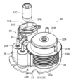
- FIG. 2 is a perspective view showing the internal structure of the main body shown in FIG. 1.
- FIG. 6 is a plan view of the internal structure of the main body shown in FIG. 5.
- FIG. FIG. 7 is an explanatory diagram of the fixing portion shown in FIGS. 5 and 6.
- FIG. (a) is a perspective view showing a state in which the main body shown in FIG.
- FIG. 8(a) is a diagram showing a state in which the main body shown in FIG. 8(a) is rotated to fix it to a flat plate
- (b) is a diagram showing the first plate and second plate of the main body and flat plate in FIG. 8(a).
- FIG. 9B is a diagram showing a state in which the second plate is located below the first plate in the positional state of the first plate and the second plate in FIG. 9(b).
- FIG. 6 is a perspective view showing the internal structure of the main body, which is different from the form shown in FIG. 5 .
- 12 is a plan view of the internal structure of the main body shown in FIG. 11.
- FIG. 12 is an external perspective view of the load increasing section, the switching gear of the load switching section, and the emergency stop section shown in FIG. 11.
- FIG. 13 is a diagram showing the internal structure of the main body shown in FIGS. 11 and 12, and is a perspective view with a load increasing part and an emergency stop part omitted.
- FIG. 15 is a plan view of the load switching unit shown in FIG. 14.
- FIG. 16(a) is an upper perspective view of the load switching unit shown in FIG. 14, and
- FIG. 16(b) is a lower perspective view of the load switching unit shown in FIG. 14.
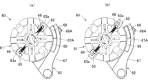
- FIG. 13 is a plan view of the emergency stop portion in a non-stop state, and (b) is a plan view of the emergency stop portion in a stopped state.
- FIG. 18 is a perspective view of the rotating section shown in FIG. 17; 19 is a partial cross-sectional view of the rotating part shown in FIG. 18.
- FIG. 18 is a perspective view of the stopper portion shown in FIG. 17.
- FIG. 1 is a perspective view of the device.
- the muscle training device 1 includes a flat plate 10 on which a user stands, and two main bodies 30.
- the flat plate 10 has a substantially rectangular shape in plan view.
- the flat plate 10 has a first side 11 and a second side 12 extending in the X direction (predetermined direction), and a third side 13 and a fourth side 14 extending in the Y direction orthogonal to the X direction.
- the flat plate 10 further includes a first corner 15 and a second corner 16 to which both ends of the first side 11 are connected to the third side 13 and the fourth side 14, and a first corner 15 and a second corner 16 of the second side 12. It has a third corner 17 and a fourth corner 18 to which both ends are connected to the third side 13 and fourth side 14 .
- a pin insertion hole 10a (FIG. 2) is formed in the first corner 15.
- the two main bodies 30 are provided so as to be attachable and detachable to the first corner 15 and the second corner 16, respectively. That is, the two main bodies 30 are provided at both ends of the first side portion 11 so as to be attachable and detachable, respectively.
- an area other than the first corner 15 and the second corner 16 to which the two main bodies 30 are attached is an area on which a user can rest.
- a handle 19 is provided at the outer edge of the third corner 17 for a user to lift the flat plate 10 placed on the floor.
- FIG. 2 is a perspective view of the flat plate 10 shown in FIG. 1 with the main body 30 removed from the first corner 15.
- FIG. 3 is a plan view of the attached portion 20 of the first corner portion 15 of the flat plate 10 shown in FIG.
- the first corner portion 15 of the flat plate 10 is provided with an attached portion 20 to which the main body 30 is attached.
- the attached part 20 has a fixing part 21 and three first plates 22 .
- the fixing part 21 has an annular shape and is fixed to the first corner part 15.
- the three first plates 22 are plate-shaped pieces, and are provided at the upper end of the inner periphery of the fixing portion 21 at equal intervals along the circumferential direction so as to protrude inward.
- Each first plate 22 has a gap 22a between it and the upper surface 10B of the flat plate 10 (see FIG. 10).
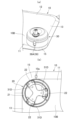
- FIG. 4 is a perspective view of the main body 30 shown in FIG. 2 viewed from below.
- the main body 30 includes a housing 31.
- the housing 31 includes a base portion 31A (see also FIGS. 5 and 6) and a substantially dome-shaped cover portion 31B.
- the base portion 31A has a substantially disk shape (see also FIG. 6), and three second plates 31D are provided on its lower surface 31C.
- Each of the second plates 31D is a plate-like piece, and is connected to each other at the center of the base portion 31A, and has a substantially three-blade propeller shape. That is, the three second plates 31D protrude radially outward at equal intervals centered on the center of the base portion 31A.
- Each second plate 31D has a gap 31e between it and the lower surface 31C of the base portion 31A (see FIG. 10).
- the cover portion 31B is provided to cover the base portion 31A, and is open at the bottom.
- the outer peripheral part of the base part 31A is supported by the lower part of the cover part 31B, and the parts other than the outer peripheral part of the base part 31A are exposed from the lower opening of the cover part 31B. Therefore, the three second plates 31D provided on the base portion 31A are exposed to the outside.
- FIG. 5 is a perspective view showing the internal structure of the main body 30 shown in FIG. 1.
- FIG. 6 is a plan view of the internal structure of the main body 30 shown in FIG. In FIG. 6, illustration of the opening 31F and the connecting portion 37C is omitted.
- the main body 30 includes a first spring spring 32 which is an elastic body, a rope winding pulley 33, two guide rollers 34, a pulley pulley 35, three pullout rollers 36A to 36C, and a string in a housing 31 (FIG. 1).
- a rope 37 and a fixing part 38 are provided.
- the first mainspring spring 32 is provided inside the first mainspring case 32A.
- the first spring case 32A is rotatable with respect to a first shaft 32B provided at its center and extending in the vertical direction.
- the center portion 32C of the first spiral spring 32 is fixed to the first shaft 32B.
- the outer end 32D of the first mainspring spring 32 is fixed to the first mainspring case 32A.
- the rope winding pulley 33 is provided below the first spring case 32A.
- the first spring case 32A is fixed to the rope winding pulley 33.
- the rope-wound pulley 33 is rotatably supported by the first shaft 32B, and is rotatable together with the first spring case 32A.
- a spiral groove 33a is formed on the outer peripheral surface of the rope winding pulley 33.
- Three arc-shaped walls 33B are provided on the outer periphery of the rope-wound pulley 33 so as to partially surround the outer periphery. The three walls 33B prevent the rope 37 from
- the two guide rollers 34 are rotatably provided by a roller shaft 34A extending in the vertical direction.
- the height of each guide roller 34 is approximately equal to the height of the rope winding pulley 33.
- the pull-out pulley 35 is rotatably provided around an axis extending in the horizontal direction.
- the pull-out pulley 35 changes the direction of the rope 37 from approximately horizontal to approximately vertical.
- Two of the three pull-out rollers 36A to 36C, 36A and 36B, are located above the pull-out pulley 35, and their rotation axes are arranged parallel to each other.
- the remaining pull-out roller 36C is located above the two pull-out rollers 36A and 36B, and is rotatable at the opening 31F of the cover portion 31B around a rotation axis perpendicular to the rotation axis of the two pull-out rollers 36A and 36B. It is provided.
- the rope 37 passes between the portion wound around the groove 33a of the rope winding pulley 33, the two guide rollers 34, the pull-out pulley 35, and the two pull-out rollers 36A and 36B from the rope winding pulley 33, and the rope 37 passes through the portion wound around the groove 33a of the rope winding pulley 33, and passes between the two guide rollers 34, the pull-out pulley 35, and the two pull-out rollers 36A and 36B, and the rope 37 passes between the rope winding pulley 33, the two guide rollers 34, the pull-out pulley 35, and the two pull-out rollers 36A, 36B. It has a portion extending outside from the opening 31F.
- the first end 37A of the rope 37 is fixed to the top of the groove 33a. Therefore, the first end 37A is connected to the outer end 32D of the first mainspring spring 32 via the rope-wound pulley 33 and the first mainspring case 32A.
- a second end 37B located on the opposite side of the first end 37A is located outside the opening 31F.
- a grip attaching portion 37D (see FIG. 11) to which a grip (not shown) held by the user is attached and a connecting portion 37C are connected to the second end portion 37B.
- FIG. 7 is an explanatory diagram of the fixing part 38 shown in FIGS. 5 and 6.
- the fixing portion 38 includes a lock switch 38A, a lock pin 38B (see FIG. 4), and a lock spring 38C.
- the lock switch 38A is supported by the cover part 31B so as to be movable up and down.
- the lock pin 38B is connected to a portion located inside the cover portion 31B of the lock switch 38A and extends downward, and the tip of the lock pin 38B can protrude downward from the cover portion 31B (see FIG. 4). .
- the lock spring 38C is provided below the opening 31F, contacts a portion of the lock switch 38A, and constantly urges the lock switch 38A and the lock pin 38B downward.
- the lock pin 38B protrudes below the cover portion 31B due to the lock spring 38C (FIG. 4).
- FIG. 8(a) is a perspective view showing the main body 30 shown in FIG. 2 in contact with the first corner 15 of the flat plate 10
- FIG. 8(b) is a perspective view of the main body 30 shown in FIG. 30 and the positional state of the first plate 22 and the second plate 31D in the flat plate 10.
- FIG. 9(a) is a diagram showing a state in which the main body 30 shown in FIG. 8(a) is rotated to fix it to the flat plate 10
- FIG. 9(b) is a diagram showing the main body 30 shown in FIG. 9(a) in a rotated state.
- FIG. 4 is a diagram showing the positional state of the first plate 22 and the second plate 31D on the flat plate 10.
- FIG. FIG. 10 is a diagram showing a state in which the second plate 31D is located below the first plate 22 in the positional state of the first plate 22 and the second plate 31D in FIG. 9(b).
- the three second plates 31D are connected to the three first plates 22 as shown in FIG. 8(b). They are located in a position that does not interfere with each other.
- the three second plates 31D and the three first plates 22 are moved together as shown in FIG. 9(b). Overlap. That is, as shown in FIG. 10, the second plate 31D is located below the first plate 22. This prevents the main body 30 from separating from the attached portion 20. As a result, the main body 30 is attached to the flat plate 10.
- the main body 30 shown in FIG. 9(a) the main body 30 is rotated in the direction opposite to the arrow A with the lock switch 38A pulled up and the lock pin 38B (see FIG. 4) removed from the pin insertion hole 10a.
- the main body 30 is removed from the flat plate 10 by lifting the main body 30 at a position where the three second plates 31D shown in FIG. 8(b) fit between the three first plates 22 and do not interfere with each other.
- the muscle training device 1 includes a flat plate 10 on which a user stands, and a main body 30 that can be attached to and removed from the flat plate 10.
- the main body 30 includes a base portion 31A, a first spiral spring 32 provided on the base portion 31A, a first end portion 37A connected to the first spiral spring 32, and a position opposite to the first end portion 37A. and a rope 37 having a second end 37B.
- the first spiral spring 32 is configured to provide the rope 37 with an elastic force that resists the tensile force when the second end 37B is pulled.
- the user can easily perform muscle training simply by attaching the main body 30 to the flat plate 10 on which the user rests.
- the weight during carrying can be distributed, so that the muscle training device 1 can be easily carried.
- the storage properties of the muscle training device 1 can be improved.
- the two main bodies 30 are installed at both ends (first corner 15 and second corner 16) of the first side 11 of the flat plate 10 so as to be attachable and detachable, respectively.
- the other areas are configured as areas on which the user can stand. Therefore, the flat plate 10 can be made smaller, and the muscle training device 1 can be made smaller.
- the second plate 31D of the main body 30 enters under the first plate 22, and prevents the main body 30 from separating from the attached part 20. It is configured as follows. In this manner, by sliding the main body 30 relative to the attached portion 20 of the flat plate 10, the main body 30 can be easily attached to and removed from the flat plate 10.
- the main body 30 can be attached to and removed from the flat plate 10 more easily.
- a muscle training device 101 (see FIG. 1) according to a second embodiment of the present disclosure will be described.
- the same members as those in the muscle training device 1 of the first embodiment are given the same reference numerals, and explanations thereof are omitted, and configurations that are different from the muscle training device 1 of the first embodiment will be explained.
- the muscle training device 101 of this embodiment includes a flat plate 10 on which a user stands, and two main bodies 130.
- the two main bodies 130 are provided so as to be attachable and detachable to the first corner 15 and the second corner 16, respectively. That is, the two main bodies 130 are provided at both ends of the first side portion 11 so as to be attachable and detachable, respectively.
- the internal structure of the main body 130 is different from that of the main body 30 of the first embodiment.
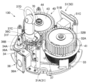
- FIG. 11 is a perspective view showing the internal structure of the main body 130 according to the second embodiment.
- FIG. 12 is a plan view of the internal structure of the main body 130 shown in FIG. 11. In FIG. 12, illustration of the opening 31F and the pull-out roller 36C is omitted.
- FIG. 13 is an external perspective view of the load increasing section 40, the switching gear 55 of the load switching section 50, and the emergency stop section 60 shown in FIG.
- the main body 130 includes a load increasing section 40, a load switching section 50, an emergency stop section 60, and a second shaft 70.
- the load increasing section 40, the load switching section 50, the emergency stop section 60, and the second shaft 70 are provided adjacent to the first spring case 32A and the rope-wound pulley 33.
- the centrifugal base 63 of the emergency stop section 60 is provided below the second spring case 43 of the load increasing section 40, and the switching gear 55 of the load switching section 50 is provided below the centrifugal base 63. It is provided.
- the second shaft 70 extending in the vertical direction passes through the second spring case 43, the centrifugal base 63, and the switching gear 55.
- the second shaft 70 is configured to be switched between a rotatable state and a non-rotatable state around its axis by the load switching unit 50.
- the load increasing section 40 includes a first gear 41, a second mainspring spring 42, a second mainspring case 43, and a second gear 44.
- the first gear 41 is fixed to the outer periphery of the first spring case 32A, and rotates integrally with the first spring case 32A.
- the second mainspring spring 42 is provided inside the second mainspring case 43.
- the second spring case 43 is rotatable with respect to a second shaft 70 passing through the center thereof.
- a center portion 42A of the second spiral spring 42 is fixed to the second shaft 70.
- the outer end 42B of the second mainspring spring 42 is fixed to the second mainspring case 43.
- the second gear 44 is fixed to the outer periphery of the second spring case 43 and rotates integrally with the second spring case 43.
- the second gear 44 meshes with the first gear 41.
- FIG. 14 is a perspective view showing the internal structure of the main body 130 shown in FIGS. 11 and 12, with the load increasing section 40 and the emergency stop section 60 omitted.
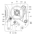
- FIG. 15 is a plan view of the load switching section 50 shown in FIG. 14. In FIG. 15, illustration of the push latch 51 is omitted.
- 16(a) is an upper perspective view of the load switching unit 50 shown in FIG. 14, and
- FIG. 16(b) is a lower perspective view of the load switching unit 50 shown in FIG. 14.
- the load switching unit 50 includes a push latch 51, a link plate 52, a switching lever 53, a switching spring 54, and a switching gear 55.
- the push latch 51 includes a support base 51A, a latch case 51B, and a pressing movement part 51C.
- the support stand 51A is fixed to the base portion 31A.
- the latch case 51B has an opening and is fixed on the base portion 31A.
- the pressing movement part 51C is inserted into the opening of the latch case 51B, and is supported so as to be slidable relative to the latch case 51B.
- the pressing moving part 51C is configured to switch between a protruding state in which its tip protrudes from the opening of the latch case 51B, and a pushed state in which most of it is pushed into the latch case 51B. has been done.
- the link plate 52 is provided below the pressing moving part 51C and the latch case 51B, and one end is connected to the pressing moving part 51C via a shaft (not shown). Therefore, the link board 52 moves along with the movement of the pressing movement section 51C. For example, the link board 52 moves along the vertical direction in FIG. 15.
- the switching lever 53 is located below the link plate 52, and is provided to be rotatable about the rotation shaft 53A with respect to the base portion 31A.
- a groove 53b is formed at the end of the switching lever 53 opposite to the rotating shaft 53A.
- a shaft 52A extending from the lower surface of the other end of the link plate 52 is inserted into the groove 53b.
- a protrusion 53C is provided on the end surface of the switching lever 53 on the switching gear 55 side.
- the switching spring 54 is provided within the groove 53b of the switching lever 53.
- the switching spring 54 is pushed by the shaft 52A of the link plate 52 and urges the switching lever 53 toward the switching gear 55 and the second shaft 70 when the pressing moving part 51C is in the pushed state.
- the switching gear 55 is fixed to the lower end of the second shaft 70.
- the switching spring 54 When the user presses the pressing moving part 51C into the pressed state, the switching spring 54 is pushed by the shaft 52A of the link plate 52, and the switching spring 54 urges the switching lever 53 toward the switching gear 55. As a result, the protrusion 53C of the switching lever 53 meshes with the switching gear 55.
- the switching gear 55 When the switching gear 55 is about to rotate counterclockwise in FIG. 15, the switching lever 53 rotates around the rotating shaft 53A due to the positional relationship between the contact surface between the protrusion 53C and the switching gear 55 and the rotating shaft 53A. It receives a force that tries to rotate it clockwise. Therefore, the switching lever 53 does not rotate, and the protrusion 53C and the switching gear 55 are never disengaged, so that the switching gear 55 is restricted from rotating.
- the switching gear 55 becomes unable to rotate counterclockwise, and the second shaft 70 also becomes unable to rotate counterclockwise.
- the rope 37 is pulled and the rope winding pulley 33 is rotated.
- the first mainspring case 32A fixed to the rope-wound pulley 33 rotates clockwise, and the first mainspring spring 32, whose outer end 32D is fixed to the first mainspring case 32A, is wound tightly.
- the rotation of the first spring case 32A causes the second spring case 43 to rotate counterclockwise via the first gear 41 and the second gear 44. Since the switching gear 55 and the second shaft 70 do not rotate and the center portion 42A of the second mainspring spring 42 is fixed to the second shaft 70, the outer end portion 42B is fixed to the second mainspring case 43.
- the second mainspring spring 42 is wound tightly.
- a force (elastic force) is generated in the first mainspring spring 32 and the second mainspring spring 42 to restore the original state, and the elastic force of the first mainspring spring 32 and the second mainspring spring 42 is applied to the rope 37. be done.
- both the first spiral spring 32 and the second spiral spring 42 are wound tightly, and elastic force is generated in the two elastic bodies, so that the load can be increased.
- the rotation of the first spring case 32A causes the second spring case 43 to rotate counterclockwise via the first gear 41 and the second gear 44. Even if the second mainspring case 43 rotates, the switching gear 55 and the second shaft 70 are in a rotatable state, so the entire second mainspring spring 42 rotates, and the second mainspring spring 42 is not wound tightly. Therefore, the elastic force of only the first spring spring 32 is applied to the rope 37 via the first spring case 32A and the rope winding pulley 33. In this way, the load can be switched by using the load switching unit 50 to make the switching gear 55 non-rotatable or rotatable.
- the link plate 52 and the switching lever 53 are connected via a switching spring 54.
- the protrusion 53C When the protrusion 53C is engaged with the switching gear 55 to make the switching gear 55 and the second shaft 70 non-rotatable, there is play in the connection between the link plate 52 and the switching lever 53, but the switching spring 54
- the protrusion 53C can always be in mesh with the switching gear 55.
- the switching gear 55 is made non-rotatable, even if the protrusion 53C and the switching gear 55 ride on each other, the above-mentioned backlash can absorb the riding on each other, and the attachment of the switching spring 54 is prevented.
- the switching gear 55 is rotated a little by the force, and the protrusion 53C can be appropriately engaged with the switching gear 55.
- the switching gear 55 when the switching gear 55 is about to rotate counterclockwise in FIG. 15 with the protrusion 53C engaged with the switching gear 55, the contact surface between the switching gear 55 and the protrusion 53C and the rotation axis Due to its positional relationship with 53A, the switching lever 53 receives a force that causes it to rotate clockwise around the rotating shaft 53A. Therefore, the protrusion 53C and the switching gear 55 do not become disengaged, and the counterclockwise rotation of the switching gear 55 is restricted.
- the load switching unit 50 switches the switching gear 55 from the rotatable state to the non-rotatable state, and the rope 37 is moved by the biasing force of the first spiral spring 32.
- the second spring case 43 When the second spring case 43 is wound around the rope winding pulley 33, the second spring case 43 rotates clockwise, so the switching gear 55 also rotates clockwise in FIG.
- the second mainspring spring 42 will be wound backwards, and there is a possibility that the second mainspring spring 42 will be damaged.
- the switching gear 55 rotates clockwise in FIG. 15, the protrusion 53C is pushed by the switching gear 55, and due to the positional relationship between the contact surface and the rotating shaft 53A, the switching lever 53 rotates counterclockwise around the rotating shaft 53A. It receives a force that tries to rotate it.
- the switching lever 53 receives a force that attempts to rotate it counterclockwise around the rotating shaft 53A, the switching lever 53 is disconnected from the switching gear 55 due to play in the connecting portion between the link plate 52 and the switching lever 53 and the switching spring 54. It is configured to be disengaged. That is, the switching gear 55 is configured to function as a one-way gear. Thereby, the second spiral spring 42 is prevented from winding in the opposite direction, and damage to the second spiral spring 42 can be prevented.
- FIG. 17 is the emergency stop section 60 shown in FIG. 13, (a) is a plan view of the emergency stop section 60 in a non-stop state, and (b) is a plan view of the emergency stop section 60 in a stopped state. .
- FIG. 18 is a perspective view of the rotating section 61 shown in FIG. 17.
- FIG. 19 is a partial cross-sectional view of the rotating part 61 shown in FIG. 18.
- FIG. 20 is a perspective view of the stopper portion 62 shown in FIG. 17. As shown in FIG. 13, the emergency stop section 60 is provided below the load increasing section 40.
- the emergency stop section 60 includes a rotating section 61 and a stopper section 62.
- the rotating part 61 includes a centrifugal base 63, two guide pins 64, two protruding pins 65, and two centrifugal springs 66.
- the centrifugal base 63 has a substantially disk shape and is fixed to the lower side of the second gear 44.
- the centrifugal base 63 rotates integrally with the second gear 44.
- a second shaft 70 passes through the center of the centrifugal base 63.
- Slits 63a are formed in the centrifugal base 63 at positions opposite to each other across the center.
- a cylindrical guide pin 64 is provided in each slit 63a so as to protrude outward.
- Each protruding pin 65 is made of a metal material, has a cylindrical shape, and is slidably provided on the outer periphery of the guide pin 64. Further, as shown in FIGS. 18 and 19, the protruding pin 65 is covered with a resin material.
- Each centrifugal spring 66 has one end connected to the centrifugal base 63 and the other end connected to the protruding pin 65. Each centrifugal spring 66 pulls the protruding pin 65 toward the center of the centrifugal base 63. As shown in FIG.
- each protruding pin 65 in the emergency stop part 60 in the non-stop state, the outer end of each protruding pin 65 is located inside the outer peripheral surface of the centrifugal base 63 due to the tensile force of each centrifugal spring 66. ing.
- the stopper section 62 includes a support section 67, a collision section 68, and a shock absorber 69.
- the support portion 67 is fixed to the base portion 31A and has a collided portion 67A along a part of the outer periphery of the centrifugal base 63.
- a groove 67b extending along the circumferential direction of the centrifugal base 63 is formed in the collided portion 67A.
- the collision part 68 and the shock absorber 69 are provided in the collision target part 67A in parallel along the circumferential direction of the centrifugal base 63.
- the shock absorber 69 is made of an elastic body.
- a collision pin 68A is fixed to the collision part 68, and the collision pin 68A is inserted into the groove 67b of the collision target part 67A.
- the rope 37 is wound around the rope winding pulley 33 at high speed.
- the first gear 41 fixed to the rope-wound pulley 33 via the first spring case 32A and the second gear 44 that meshes with the first gear 41 rotate clockwise in FIG. 12 at high speed. Therefore, the centrifugal base 63 fixed to the second gear 44 also rotates clockwise in FIG. 17 at high speed.
- a centrifugal force larger than the tensile force of each centrifugal spring 66 acts on each protruding pin 65, and each protruding pin 65 moves outward from the outer peripheral surface of the centrifugal base 63, as shown in FIG. 17(b). stand out.
- the protruding pin 65 collides with the colliding portion 68 of the stopper portion 62 . Due to the collision of the protruding pin 65, the collision portion 68 slides toward the impact absorbing material 69, and the impact is absorbed by the impact absorbing material 69.
- the centrifugal base 63 stops rotating, the second gear 44 to which the centrifugal base 63 is fixed stops rotating, the first gear 41 that meshes with the second gear 44 stops rotating, and the rope winding pulley 33 stops rotating.
- the rotation stops and the action of pulling back the rope 37 stops.
- the muscle training device 101 includes a base portion 31A, a first spiral spring 32 and a second spiral spring 42 provided on the base portion 31A, a first end portion 37A connected to the first spiral spring 32, and a first end portion 37A.
- the rope 37 has a second end 37B located on the opposite side from the portion 37A.
- the first mainspring spring 32 and the second mainspring spring 42 are configured to provide the rope 37 with an elastic force that resists the tensile force when the second end 37B is pulled. With such a configuration, the load on the user in the muscle training device 101 can be increased by the first spiral spring 32 and the second spiral spring 42.
- the muscle training device 101 further includes a load switching unit 50 that can be switched to generate an elastic force that resists the tensile force only in the first mainspring spring 32 or in the first mainspring spring 32 and the second mainspring spring 42.
- the load switching section 50 includes a switching lever 53 and a switching gear 55.
- the switching gear 55 is fixed to a second shaft 70 to which the center portion 42A of the second mainspring spring 42 is fixed.
- the switching lever 53 meshes with the switching gear 55 to make the switching gear 55 non-rotatable, and the center part 42A of the second mainspring spring 42 is made non-rotatable, so that the second mainspring spring 42 can be wound up.
- the switching lever 53 separates from the switching gear 55 to make the switching gear 55 rotatable, and the center portion 42A of the second mainspring spring 42 is made rotatable together with the second shaft 70, so that the second mainspring spring 42 cannot be tightened. It becomes a state.
- the muscle training device 101 has the same effects as the muscle training device 1. Furthermore, with the above configuration regarding the switching lever 53 and the switching gear 55, the load can be switched according to the user's request, and the usability of the muscle training device 101 can be improved.
- the muscle training device 101 is configured such that when the rope 37 on which the user's force is not applied is pulled back due to the elastic force generated in the first spiral spring 32 and the second spiral spring 42 and applied to the rope 37, the rope 37 is It further includes an emergency stop part 60 that stops being pulled back.
- the emergency stop section 60 includes a rotating section 61 that rotates due to elastic force, and a stopper section 62 that stops the rotation of the rotating section 61.
- the rotating part 61 has a protruding pin 65 that projects outward from the rotating part 61 by rotation due to elastic force.
- the stopper part 62 is configured to stop the rotation of the rotating part 61 and stop the rope 37 from being pulled back when the protruding pin 65 protruding outward from the rotating part 61 collides with the stopper part 62 .
- the flat plate 10 may be foldable. Although the main bodies 30 and 130 are provided at the corners 15 and 16 of the flat plate 10, they may be installed and removed at locations other than the corners 15 and 16, such as the center of the flat plate 10. Although the flat plate 10 has a substantially rectangular shape in plan view, it may have another shape, such as a trapezoidal shape. Although two spiral springs 32 and 42 were provided inside the main body 130 of the second embodiment, the number of spiral springs may be further increased to create a configuration with an even higher load. Although the emergency stop part 60 was provided below the load increasing part 40, it may be provided below the rope winding pulley 33, or it may be provided in the main body 30 of the muscle training device 1 of the first embodiment. Good too.
Landscapes
- Health & Medical Sciences (AREA)
- General Health & Medical Sciences (AREA)
- Physical Education & Sports Medicine (AREA)
- Life Sciences & Earth Sciences (AREA)
- Biophysics (AREA)
- Orthopedic Medicine & Surgery (AREA)
- Rehabilitation Tools (AREA)
Priority Applications (1)
| Application Number | Priority Date | Filing Date | Title |
|---|---|---|---|
| US18/905,291 US20250025737A1 (en) | 2022-04-11 | 2024-10-03 | Muscle training device |
Applications Claiming Priority (2)
| Application Number | Priority Date | Filing Date | Title |
|---|---|---|---|
| JP2022065325A JP7733608B2 (ja) | 2022-04-11 | 2022-04-11 | 筋肉トレーニング装置 |
| JP2022-065325 | 2022-04-11 |
Related Child Applications (1)
| Application Number | Title | Priority Date | Filing Date |
|---|---|---|---|
| US18/905,291 Continuation US20250025737A1 (en) | 2022-04-11 | 2024-10-03 | Muscle training device |
Publications (1)
| Publication Number | Publication Date |
|---|---|
| WO2023199684A1 true WO2023199684A1 (ja) | 2023-10-19 |
Family
ID=88329433
Family Applications (1)
| Application Number | Title | Priority Date | Filing Date |
|---|---|---|---|
| PCT/JP2023/009907 Ceased WO2023199684A1 (ja) | 2022-04-11 | 2023-03-14 | 筋肉トレーニング装置 |
Country Status (3)
| Country | Link |
|---|---|
| US (1) | US20250025737A1 (https=) |
| JP (1) | JP7733608B2 (https=) |
| WO (1) | WO2023199684A1 (https=) |
Families Citing this family (1)
| Publication number | Priority date | Publication date | Assignee | Title |
|---|---|---|---|---|
| KR20260038690A (ko) * | 2024-09-12 | 2026-03-19 | 주식회사 스포첵 | 운동기구 |
Citations (6)
| Publication number | Priority date | Publication date | Assignee | Title |
|---|---|---|---|---|
| JPS57155190A (en) * | 1981-03-21 | 1982-09-25 | Shiyunyuu So | Metal fitting for channel type lashing |
| US20130090216A1 (en) * | 2011-10-11 | 2013-04-11 | Broc Jackson | Exercise equipment |
| US20150011368A1 (en) * | 2012-01-25 | 2015-01-08 | Kinvestix Ltd. | Magnetic pulley resistance exerciser |
| US20170014661A1 (en) * | 2015-07-14 | 2017-01-19 | Global Win Technology Co., Ltd. | Damping device |
| US20190001175A1 (en) * | 2017-06-30 | 2019-01-03 | Christopher Lee Wagner | Portable functional training device |
| WO2021000048A1 (en) * | 2019-07-02 | 2021-01-07 | Rubber Recon Inc. | Strap connection systems, quick connectors, and related systems and methods |
-
2022
- 2022-04-11 JP JP2022065325A patent/JP7733608B2/ja active Active
-
2023
- 2023-03-14 WO PCT/JP2023/009907 patent/WO2023199684A1/ja not_active Ceased
-
2024
- 2024-10-03 US US18/905,291 patent/US20250025737A1/en active Pending
Patent Citations (6)
| Publication number | Priority date | Publication date | Assignee | Title |
|---|---|---|---|---|
| JPS57155190A (en) * | 1981-03-21 | 1982-09-25 | Shiyunyuu So | Metal fitting for channel type lashing |
| US20130090216A1 (en) * | 2011-10-11 | 2013-04-11 | Broc Jackson | Exercise equipment |
| US20150011368A1 (en) * | 2012-01-25 | 2015-01-08 | Kinvestix Ltd. | Magnetic pulley resistance exerciser |
| US20170014661A1 (en) * | 2015-07-14 | 2017-01-19 | Global Win Technology Co., Ltd. | Damping device |
| US20190001175A1 (en) * | 2017-06-30 | 2019-01-03 | Christopher Lee Wagner | Portable functional training device |
| WO2021000048A1 (en) * | 2019-07-02 | 2021-01-07 | Rubber Recon Inc. | Strap connection systems, quick connectors, and related systems and methods |
Also Published As
| Publication number | Publication date |
|---|---|
| JP7733608B2 (ja) | 2025-09-03 |
| JP2023155783A (ja) | 2023-10-23 |
| US20250025737A1 (en) | 2025-01-23 |
Similar Documents
| Publication | Publication Date | Title |
|---|---|---|
| WO2023199684A1 (ja) | 筋肉トレーニング装置 | |
| EP4173678A1 (en) | Treadmill | |
| JP2023171679A (ja) | コマ玩具及びコマ玩具セット | |
| JP5966164B2 (ja) | 原稿圧着板開閉装置並びに事務機器 | |
| KR101360601B1 (ko) | 힌지장치 및 개폐장치 및 휴대기기 | |
| KR20130033758A (ko) | 선박용 맨홀 안전덮개 | |
| US11802431B2 (en) | Document cover closer and office equipment using the same | |
| CN117780777B (zh) | 一种锁紧定位机构及旋转折叠定位装置 | |
| JP5565854B2 (ja) | スライドレールユニット、ラックキャビネット、取外具、及び、取外方法 | |
| JP2512704Y2 (ja) | セルフタイマ―装置 | |
| KR102369522B1 (ko) | 하우스형 트램폴린 | |
| JP2019158937A (ja) | 蓋体開閉装置並びに各種機器 | |
| US12606080B2 (en) | Safety ratchet strap tensioner | |
| KR102789663B1 (ko) | 운반용 팔레트에 설치된 결박장치 | |
| JP2008233887A (ja) | 緩衝装置 | |
| JP2007139178A (ja) | 双方向ラチエットヒンジ | |
| JP3573301B2 (ja) | 家具転倒防止具 | |
| KR102866979B1 (ko) | 가정용 트램폴린 | |
| JP2003330063A (ja) | シャッタ装置 | |
| CN222983643U (zh) | 俯卧撑盘以及锻炼装置 | |
| JP2016104940A (ja) | キーユニット | |
| JP2003275029A (ja) | 折り畳みテーブル | |
| JP4893398B2 (ja) | 鍵盤楽器 | |
| JP4965194B2 (ja) | 遊技機のための伸縮型ヒンジ装置 | |
| KR200298601Y1 (ko) | 신체체력 단련용 보드 |
Legal Events
| Date | Code | Title | Description |
|---|---|---|---|
| 121 | Ep: the epo has been informed by wipo that ep was designated in this application |
Ref document number: 23788106 Country of ref document: EP Kind code of ref document: A1 |
|
| NENP | Non-entry into the national phase |
Ref country code: DE |
|
| 122 | Ep: pct application non-entry in european phase |
Ref document number: 23788106 Country of ref document: EP Kind code of ref document: A1 |