WO2023199491A1 - 無線通信装置、無線通信方法及び無線通信システム - Google Patents
無線通信装置、無線通信方法及び無線通信システム Download PDFInfo
- Publication number
- WO2023199491A1 WO2023199491A1 PCT/JP2022/017871 JP2022017871W WO2023199491A1 WO 2023199491 A1 WO2023199491 A1 WO 2023199491A1 JP 2022017871 W JP2022017871 W JP 2022017871W WO 2023199491 A1 WO2023199491 A1 WO 2023199491A1
- Authority
- WO
- WIPO (PCT)
- Prior art keywords
- wireless communication
- channel
- signal
- carrier sense
- determination
- Prior art date
- Legal status (The legal status is an assumption and is not a legal conclusion. Google has not performed a legal analysis and makes no representation as to the accuracy of the status listed.)
- Ceased
Links
Images


Classifications
-
- H—ELECTRICITY
- H04—ELECTRIC COMMUNICATION TECHNIQUE
- H04W—WIRELESS COMMUNICATION NETWORKS
- H04W74/00—Wireless channel access
- H04W74/08—Non-scheduled access, e.g. ALOHA
- H04W74/0808—Non-scheduled access, e.g. ALOHA using carrier sensing, e.g. carrier sense multiple access [CSMA]
-
- H—ELECTRICITY
- H04—ELECTRIC COMMUNICATION TECHNIQUE
- H04W—WIRELESS COMMUNICATION NETWORKS
- H04W74/00—Wireless channel access
- H04W74/08—Non-scheduled access, e.g. ALOHA
- H04W74/0866—Non-scheduled access, e.g. ALOHA using a dedicated channel for access
-
- H—ELECTRICITY
- H04—ELECTRIC COMMUNICATION TECHNIQUE
- H04W—WIRELESS COMMUNICATION NETWORKS
- H04W84/00—Network topologies
- H04W84/02—Hierarchically pre-organised networks, e.g. paging networks, cellular networks, WLAN [Wireless Local Area Network] or WLL [Wireless Local Loop]
- H04W84/10—Small scale networks; Flat hierarchical networks
- H04W84/12—WLAN [Wireless Local Area Networks]
Definitions
- the present disclosure relates to a wireless communication device, a wireless communication method, and a wireless communication system, and more particularly, to a wireless communication device, a wireless communication method, and a wireless communication system that perform communication between a plurality of wireless communication modules.
- each wireless communication module uses a sufficiently distant frequency channel to completely avoid the above-mentioned collision of wireless signals.
- carrier sense is performed to avoid collisions of wireless signals due to matching wireless transmission timings.
- Carrier sense is a function that checks whether a signal is being transmitted from another terminal for a certain period of time + random time before transmitting a signal from the own terminal. The signals checked at this time are limited to the range of frequency channels used by the terminal itself.
- the present disclosure provides a wireless communication device that can avoid signal interference between multiple wireless communication modules using adjacent channels by expanding the range of frequency channels on which carrier sense is performed to include adjacent channels.
- the primary purpose is to provide.
- a first aspect of the present disclosure includes a plurality of wireless communication modules each having a signal receiving section, an access control section, and a signal transmitting section, wherein the signal receiving section receives a wireless communication signal, and the access control section receives a channel of an occupied frequency.
- the signal transmission unit is a wireless communication device that performs a carrier sense determination on the adjacent channel in addition to the above, and performs wireless transmission based on the determination.
- a second aspect of the present disclosure is a reception process in which a plurality of wireless communication modules receive a wireless communication signal, a determination process in which carrier sense is determined for an adjacent channel in addition to an occupied frequency channel, and a result of the determination process. It is preferable that the wireless communication method includes a transmission process of performing wireless communication based on.
- a third aspect of the present disclosure includes a signal receiving unit that receives a wireless communication signal, an access control unit that performs a carrier sense determination for an adjacent channel in addition to an occupied frequency channel, and a wireless communication unit that performs or performs wireless communication based on the determination. It is preferable that the wireless communication system includes a plurality of signal transmitting units to be canceled.
- a wireless communication device that can avoid signal interference between multiple wireless communication modules that use adjacent channels by expanding the frequency range in which carrier sense is performed to adjacent channels. , it becomes possible to provide a wireless communication method and a wireless communication system.
- FIG. 1 is a diagram showing the configuration of a wireless communication system according to Embodiment 1 of the present disclosure.
- FIG. 2 is a diagram showing a configuration of frequency channels according to Embodiment 1 of the present disclosure.
- 1 is a diagram showing the configuration of a wireless communication repeater according to the present disclosure.
- 3 is a graph showing a range of frequency channels detected by carrier sense according to Embodiment 1 of the present disclosure.
- FIG. 7 is a diagram showing a frame of a wireless signal according to Embodiment 2.
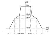
- FIG. 1 is a graph showing a transmission spectrum mask of a radio signal spectrum. Here, the default transmission spectrum mask for the IEEE 802.11ah 1 MHz band is shown.
- the power spectral density may be -20 dBr (decibels relative to reference level).
- the signal power density of the main lobe is 3 dBm/100 kHz, it becomes -17 dBm/100 kHz at a frequency position 600 kHz away from the center.
- Attenuation in the wireless space is sufficient if it is, for example, 20 dB or less. That is, in the transmission spectrum of a 1 MHz wide channel, even frequencies outside the channel range that are 0.5 MHz or more away from the center frequency are considered to have insufficient attenuation. Therefore, when this signal is received in close proximity, attenuation is insufficient, and leakage power alone causes significant interference. In other words, it can be seen that when dividing the channels by frequency to avoid radio interference, adjacent frequency channels may not be able to fulfill their role satisfactorily.
- FIG. 2 is a graph showing an example of the reception strength observed at the repeater.
- Channel #1 is a frequency channel used by wireless communication module #1
- Channel #2 is a frequency channel used by wireless communication module #2.
- Channel #1 and Channel #2 are adjacent frequency channels.
- wireless communication module #1 starts signal transmission using Channel #1 while wireless communication module #2 is receiving a signal on Channel #2.
- the carrier sense of wireless communication module #1 detects a signal only within the range of Channel #1. Therefore, wireless communication module #1 detects only the power leaked from Channel #2 to Channel #1, and determines the carrier sense result. At this time, if the power leaked from Channel #2 is lower than the carrier sense threshold, wireless communication module #2 is determined to be in an idle state. Therefore, wireless communication module #1 starts signal transmission using Channel #1.
- wireless communication module #2 is actually receiving the signal of Channel #2.
- wireless communication module #1 starts signal transmission here, power leaks from Channel #1 to Channel #2. Due to interference from this leakage power, a demodulation error occurs in the signal that wireless communication module #2 is receiving on Channel #2, resulting in a failure in signal reception.
- the frequency range for carrier sensing is expanded to the adjacent channels. This avoids signal interference between multiple wireless communication modules that use adjacent channels.
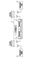
- FIG. 3 is a diagram showing the configuration of a wireless communication system according to Embodiment 1 of the present disclosure.
- the wireless communication system includes a wireless communication repeater 2.
- the wireless communication repeater 2 has a repeater 4, which is, for example, an SOC (System On Chip).
- the repeater 4 relays wireless communication between wireless communication modules 6 and 8, which are wireless communication modules.
- the wireless communication modules 6 and 8 are, for example, NICs (Network Interface Controllers).
- the wireless communication module 6 performs wireless communication with the wireless communication master device 10 .
- the wireless communication module 8 performs wireless communication with a plurality of wireless communication handsets 12.
- FIG. 4 is a diagram showing the configuration of frequency channels according to Embodiment 1 of the present disclosure.
- frequency Channel #1 is used for wireless communication between the wireless communication module 6 and wireless communication base device 10
- frequency Channel #1 is used for wireless communication between the wireless communication module 8 and wireless communication slave device 12. Use 2.
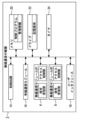
- FIG. 5 is a diagram showing the configuration of a wireless communication repeater according to the present disclosure.
- the wireless communication repeater 2 includes wireless communication modules 6 and 8, as also shown in FIG.
- the wireless communication modules 6 and 8 have a signal receiving section that receives wireless communication, an access control section that performs carrier sense determination on the signal received by the signal receiving section, and a signal transmitting section that transmits wireless communication (not shown). . Further, the wireless communication modules 6 and 8 have adjacent occupied frequencies. Note that although three or more wireless communication modules may be included, this disclosure shows a configuration that includes two wireless communication modules.
- the wireless communication repeater 2 includes a control circuit 14.
- the control circuit 14 controls the observation period and the start timing using management information according to a built-in management program.
- the wireless communication repeater 2 includes a wired communication module 16.
- the wired communication module 16 has a function of performing wired communication, and is used, for example, when performing wired communication with another repeater.
- the wireless communication repeater 2 also includes a user interface 18 .
- the user interface 18 is a module used when changing the settings of the wireless communication repeater 2 from the outside, and is, for example, a controller operated by the user.
- the wireless communication repeater 2 includes a memory 20. Memory 20 has control programs and management information.
- the wireless communication repeater 2 also includes a drive 22 .
- the drive 22 has a storage medium and stores setting information of the repeater and the like.
- the wireless communication repeater 2 includes a timer 24 .
- the timer 24 measures time related to wireless communication of the repeater.
- control unit included in the device of the present disclosure can also be realized by a computer and a program, and the program can be recorded on a recording medium or provided through a network.
- FIG. 6 is a graph showing the range of frequency channels detected by carrier sense according to Embodiment 1 of the present disclosure.
- Channel #1 is the occupied frequency of the wireless communication module 6
- Channel #2 is the occupied frequency of the wireless communication module 8, and as described above, the respective occupied frequencies are adjacent to each other.
- the frequency channel including the adjacent channel is Let the range be the career sense range.
- the wireless communication module 6 sets the range of frequency channels including not only Channel #1 but also adjacent Channel #2 as a carrier sense range.
- carrier sensing can be performed in consideration of adjacent channels affected by leakage power.
- a filter for reception is prepared for each channel. For example, by changing this to a filter that includes all adjacent channels, the above configuration can be realized without complicating the configuration at the time of reception.
- the carrier sense threshold used for threshold determination in the signal receiving section in the wireless communication module may be changed. Since the two wireless communication modules 6 and 8 according to the first embodiment are devices of the same model included in the same wireless communication repeater 2, the power of the signals each receives is also about the same.
- a case will be considered in which the wireless communication module 6 performs carrier sense.
- the wireless communication module 6 performs carrier sense.
- the power leaking from Channel #2 to Channel #1 is lower than the power used by Channel #1 for wireless communication.
- the wireless communication power is low, such as when the wireless communication module 8 starts and ends wireless communication, even if the wireless communication module 6 performs wireless communication, it is unlikely that wireless interference will occur. Become. Based on the above, it is considered that there is no need to refrain from wireless communication of the wireless communication module 6 unless the power consumption of the wireless communication module 8 is sufficiently high.
- the carrier sense threshold for the adjacent channel is set higher than the occupied frequency. Specifically, when carrying out carrier sense in the wireless communication module 6, the carrier sense threshold of Channel #2 is set higher than the carrier sense threshold of Channel #1.
- the determination of the carrier sense result may be changed after referring to the reception state of each wireless communication module. For example, by notifying the transmission failure rate of the wireless communication handset 12, the reception failure rate of the wireless communication module 8 can be detected. Here, if the reception failure rate of the wireless communication module 8 is high, there is a possibility that the leakage power by the wireless communication module 6 is larger than expected and wireless interference is occurring. Therefore, the determination is changed so that the wireless communication of the wireless communication module 6 is stopped. As described above, by changing the determination of the carrier sense result of the wireless communication module 6 based on information such as the reception failure rate of the adjacent wireless communication module, more efficient wireless communication can be performed.
- Embodiment 2 has the same device configuration as Embodiment 1, but differs in that carrier sense is performed only for specific radio signals.
- the BSS identifier such as the BSS color of the signal received on the adjacent channel is also grasped.
- carrier sense determination only signals related to the wireless communication module and the repeater including the wireless communication module are subjected to carrier sense determination. In this way, by making a determination only on wireless signals whose interference should be avoided, it is possible to avoid an event in which wireless communication is excessively restricted.
- FIG. 7 is a diagram showing a frame of a wireless signal according to the second embodiment.
- One method for identifying wireless signals whose interference should be avoided is to use a COLOR field that identifies a BSS (Basic Service Set), which is a wireless LAN cell.
- BSS Basic Service Set
- the value of the COLOR field is used as a simple BSS identifier.
- the carrier sense threshold for this value is set low.
- the same COLOR field value is set for identifiers used by wireless communication modules in the same housing, and the carrier sense threshold is changed when that value is detected.
- the value of the COLOR field used by nearby wireless communication modules is known, and the carrier sense threshold is changed when that value is detected.
- the carrier sense threshold for this value is set high. Since the COLOR field has several types of bits, there is a high probability that different values will be set for terminals outside the wireless communication system. Therefore, for example, the carrier sense threshold is changed for values other than those in the COLOR field that may interfere. As a result, the number of transmission opportunities from the own terminal can be increased, and throughput can be expected to improve.
Landscapes
- Engineering & Computer Science (AREA)
- Computer Networks & Wireless Communication (AREA)
- Signal Processing (AREA)
- Mobile Radio Communication Systems (AREA)
Priority Applications (3)
| Application Number | Priority Date | Filing Date | Title |
|---|---|---|---|
| PCT/JP2022/017871 WO2023199491A1 (ja) | 2022-04-14 | 2022-04-14 | 無線通信装置、無線通信方法及び無線通信システム |
| US18/854,851 US20250310991A1 (en) | 2022-04-14 | 2022-04-14 | Wireless communication device, wireless communication method, and wireless communication system |
| JP2024514759A JPWO2023199491A1 (https=) | 2022-04-14 | 2022-04-14 |
Applications Claiming Priority (1)
| Application Number | Priority Date | Filing Date | Title |
|---|---|---|---|
| PCT/JP2022/017871 WO2023199491A1 (ja) | 2022-04-14 | 2022-04-14 | 無線通信装置、無線通信方法及び無線通信システム |
Publications (1)
| Publication Number | Publication Date |
|---|---|
| WO2023199491A1 true WO2023199491A1 (ja) | 2023-10-19 |
Family
ID=88329408
Family Applications (1)
| Application Number | Title | Priority Date | Filing Date |
|---|---|---|---|
| PCT/JP2022/017871 Ceased WO2023199491A1 (ja) | 2022-04-14 | 2022-04-14 | 無線通信装置、無線通信方法及び無線通信システム |
Country Status (3)
| Country | Link |
|---|---|
| US (1) | US20250310991A1 (https=) |
| JP (1) | JPWO2023199491A1 (https=) |
| WO (1) | WO2023199491A1 (https=) |
Cited By (1)
| Publication number | Priority date | Publication date | Assignee | Title |
|---|---|---|---|---|
| WO2026053799A1 (ja) * | 2024-09-04 | 2026-03-12 | ソニーグループ株式会社 | 無線通信装置及び無線通信方法 |
Citations (4)
| Publication number | Priority date | Publication date | Assignee | Title |
|---|---|---|---|---|
| JP2017098676A (ja) * | 2015-11-19 | 2017-06-01 | キヤノン株式会社 | 制御装置、制御方法、およびプログラム |
| JP2018527840A (ja) * | 2015-09-15 | 2018-09-20 | クゥアルコム・インコーポレイテッドQualcomm Incorporated | 近隣の通信ネットワークにおけるワイヤレス通信リソースの再利用のためのシステムおよび方法 |
| JP2021019242A (ja) * | 2019-07-18 | 2021-02-15 | コニカミノルタ株式会社 | 情報処理装置及びプログラム |
| WO2022049666A1 (ja) * | 2020-09-02 | 2022-03-10 | 日本電信電話株式会社 | 無線通信方法及び無線通信装置 |
Family Cites Families (1)
| Publication number | Priority date | Publication date | Assignee | Title |
|---|---|---|---|---|
| JP6089756B2 (ja) * | 2013-02-18 | 2017-03-08 | 株式会社バッファロー | 無線通信装置、及び、無線通信を行なう方法 |
-
2022
- 2022-04-14 JP JP2024514759A patent/JPWO2023199491A1/ja active Pending
- 2022-04-14 US US18/854,851 patent/US20250310991A1/en active Pending
- 2022-04-14 WO PCT/JP2022/017871 patent/WO2023199491A1/ja not_active Ceased
Patent Citations (4)
| Publication number | Priority date | Publication date | Assignee | Title |
|---|---|---|---|---|
| JP2018527840A (ja) * | 2015-09-15 | 2018-09-20 | クゥアルコム・インコーポレイテッドQualcomm Incorporated | 近隣の通信ネットワークにおけるワイヤレス通信リソースの再利用のためのシステムおよび方法 |
| JP2017098676A (ja) * | 2015-11-19 | 2017-06-01 | キヤノン株式会社 | 制御装置、制御方法、およびプログラム |
| JP2021019242A (ja) * | 2019-07-18 | 2021-02-15 | コニカミノルタ株式会社 | 情報処理装置及びプログラム |
| WO2022049666A1 (ja) * | 2020-09-02 | 2022-03-10 | 日本電信電話株式会社 | 無線通信方法及び無線通信装置 |
Cited By (1)
| Publication number | Priority date | Publication date | Assignee | Title |
|---|---|---|---|---|
| WO2026053799A1 (ja) * | 2024-09-04 | 2026-03-12 | ソニーグループ株式会社 | 無線通信装置及び無線通信方法 |
Also Published As
| Publication number | Publication date |
|---|---|
| US20250310991A1 (en) | 2025-10-02 |
| JPWO2023199491A1 (https=) | 2023-10-19 |
Similar Documents
| Publication | Publication Date | Title |
|---|---|---|
| US10623125B2 (en) | Resource utilization for uplink transmission based on indicated interference | |
| US8886203B2 (en) | Dynamic channel reuse in multi-access communication systems | |
| EP3536005B1 (en) | Cooperation between nodes operating in licensed and unlicensed spectrum for channel access in unlicensed spectrum | |
| KR101131750B1 (ko) | 단일 전자 디바이스 내에 공동배치된 다수의 무선 통신 프로토콜에 대한 통신의 조정 | |
| US8155032B2 (en) | Adaptive scheduling for half-duplex wireless terminals | |
| US9788363B2 (en) | LTE and WLAN/bluetooth coexistence | |
| CN110536468A (zh) | 无线通信系统、通信单元,以及用于调度的方法 | |
| JP2013538499A (ja) | 移動通信装置における装置内共存干渉軽減のトリガー方法 | |
| CN107040984B (zh) | 一种非授权频段上行功率控制方法及相关设备 | |
| WO2012064093A2 (en) | Method and apparatus of handling in-device co-existence interference in a multi-radio environment | |
| JP7786624B2 (ja) | 方法および無線アクセスネットワークノード | |
| US9220102B2 (en) | Low power base station and communication control method | |
| EP2522173B1 (en) | Combined scan | |
| JP2017135699A (ja) | 同じ周波数帯域の2つの無線周波数モジュールをもつワイヤレスアクセスポイントおよび信号干渉低減方法 | |
| KR20100132064A (ko) | 조정되지 않은 시간 분할 듀플렉스 통신 네트워크들 간의 동기화 | |
| WO2015066861A1 (en) | Optimizing cre configuration | |
| WO2023199491A1 (ja) | 無線通信装置、無線通信方法及び無線通信システム | |
| Verma et al. | Throughput enhancement to the cognitive radio networks under the precaution based cooperation of the primary users | |
| CN111836373B (zh) | 一种非授权载波小区的接入方法和系统 | |
| WO2023199480A1 (ja) | 無線通信装置、無線通信方法及び無線通信システム | |
| CN120786562A (zh) | 通信方法及装置 |
Legal Events
| Date | Code | Title | Description |
|---|---|---|---|
| 121 | Ep: the epo has been informed by wipo that ep was designated in this application |
Ref document number: 22937470 Country of ref document: EP Kind code of ref document: A1 |
|
| ENP | Entry into the national phase |
Ref document number: 2024514759 Country of ref document: JP Kind code of ref document: A |
|
| WWE | Wipo information: entry into national phase |
Ref document number: 18854851 Country of ref document: US |
|
| NENP | Non-entry into the national phase |
Ref country code: DE |
|
| 122 | Ep: pct application non-entry in european phase |
Ref document number: 22937470 Country of ref document: EP Kind code of ref document: A1 |
|
| WWP | Wipo information: published in national office |
Ref document number: 18854851 Country of ref document: US |