WO2023199491A1 - 無線通信装置、無線通信方法及び無線通信システム - Google Patents
無線通信装置、無線通信方法及び無線通信システム Download PDFInfo
- Publication number
- WO2023199491A1 WO2023199491A1 PCT/JP2022/017871 JP2022017871W WO2023199491A1 WO 2023199491 A1 WO2023199491 A1 WO 2023199491A1 JP 2022017871 W JP2022017871 W JP 2022017871W WO 2023199491 A1 WO2023199491 A1 WO 2023199491A1
- Authority
- WO
- WIPO (PCT)
- Prior art keywords
- wireless communication
- channel
- signal
- carrier sense
- determination
- Prior art date
Links
- 238000000034 method Methods 0.000 title claims abstract description 13
- 230000005540 biological transmission Effects 0.000 claims abstract description 8
- 230000008054 signal transmission Effects 0.000 abstract description 6
- 238000010586 diagram Methods 0.000 description 8
- 238000000411 transmission spectrum Methods 0.000 description 4
- 238000007796 conventional method Methods 0.000 description 2
- 230000006870 function Effects 0.000 description 2
- 238000005204 segregation Methods 0.000 description 2
- 230000035945 sensitivity Effects 0.000 description 2
- 238000001228 spectrum Methods 0.000 description 2
- 238000000926 separation method Methods 0.000 description 1
- 230000003595 spectral effect Effects 0.000 description 1
Images


Classifications
-
- H—ELECTRICITY
- H04—ELECTRIC COMMUNICATION TECHNIQUE
- H04W—WIRELESS COMMUNICATION NETWORKS
- H04W16/00—Network planning, e.g. coverage or traffic planning tools; Network deployment, e.g. resource partitioning or cells structures
- H04W16/24—Cell structures
- H04W16/26—Cell enhancers or enhancement, e.g. for tunnels, building shadow
Definitions
- the present disclosure relates to a wireless communication device, a wireless communication method, and a wireless communication system, and more particularly, to a wireless communication device, a wireless communication method, and a wireless communication system that perform communication between a plurality of wireless communication modules.
- each wireless communication module uses a sufficiently distant frequency channel to completely avoid the above-mentioned collision of wireless signals.
- carrier sense is performed to avoid collisions of wireless signals due to matching wireless transmission timings.
- Carrier sense is a function that checks whether a signal is being transmitted from another terminal for a certain period of time + random time before transmitting a signal from the own terminal. The signals checked at this time are limited to the range of frequency channels used by the terminal itself.
- the present disclosure provides a wireless communication device that can avoid signal interference between multiple wireless communication modules using adjacent channels by expanding the range of frequency channels on which carrier sense is performed to include adjacent channels.
- the primary purpose is to provide.
- a first aspect of the present disclosure includes a plurality of wireless communication modules each having a signal receiving section, an access control section, and a signal transmitting section, wherein the signal receiving section receives a wireless communication signal, and the access control section receives a channel of an occupied frequency.
- the signal transmission unit is a wireless communication device that performs a carrier sense determination on the adjacent channel in addition to the above, and performs wireless transmission based on the determination.
- a second aspect of the present disclosure is a reception process in which a plurality of wireless communication modules receive a wireless communication signal, a determination process in which carrier sense is determined for an adjacent channel in addition to an occupied frequency channel, and a result of the determination process. It is preferable that the wireless communication method includes a transmission process of performing wireless communication based on.
- a third aspect of the present disclosure includes a signal receiving unit that receives a wireless communication signal, an access control unit that performs a carrier sense determination for an adjacent channel in addition to an occupied frequency channel, and a wireless communication unit that performs or performs wireless communication based on the determination. It is preferable that the wireless communication system includes a plurality of signal transmitting units to be canceled.
- a wireless communication device that can avoid signal interference between multiple wireless communication modules that use adjacent channels by expanding the frequency range in which carrier sense is performed to adjacent channels. , it becomes possible to provide a wireless communication method and a wireless communication system.
- FIG. 1 is a diagram showing the configuration of a wireless communication system according to Embodiment 1 of the present disclosure.
- FIG. 2 is a diagram showing a configuration of frequency channels according to Embodiment 1 of the present disclosure.
- 1 is a diagram showing the configuration of a wireless communication repeater according to the present disclosure.
- 3 is a graph showing a range of frequency channels detected by carrier sense according to Embodiment 1 of the present disclosure.
- FIG. 7 is a diagram showing a frame of a wireless signal according to Embodiment 2.
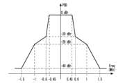
- FIG. 1 is a graph showing a transmission spectrum mask of a radio signal spectrum. Here, the default transmission spectrum mask for the IEEE 802.11ah 1 MHz band is shown.
- the power spectral density may be -20 dBr (decibels relative to reference level).
- the signal power density of the main lobe is 3 dBm/100 kHz, it becomes -17 dBm/100 kHz at a frequency position 600 kHz away from the center.
- Attenuation in the wireless space is sufficient if it is, for example, 20 dB or less. That is, in the transmission spectrum of a 1 MHz wide channel, even frequencies outside the channel range that are 0.5 MHz or more away from the center frequency are considered to have insufficient attenuation. Therefore, when this signal is received in close proximity, attenuation is insufficient, and leakage power alone causes significant interference. In other words, it can be seen that when dividing the channels by frequency to avoid radio interference, adjacent frequency channels may not be able to fulfill their role satisfactorily.
- FIG. 2 is a graph showing an example of the reception strength observed at the repeater.
- Channel #1 is a frequency channel used by wireless communication module #1
- Channel #2 is a frequency channel used by wireless communication module #2.
- Channel #1 and Channel #2 are adjacent frequency channels.
- wireless communication module #1 starts signal transmission using Channel #1 while wireless communication module #2 is receiving a signal on Channel #2.
- the carrier sense of wireless communication module #1 detects a signal only within the range of Channel #1. Therefore, wireless communication module #1 detects only the power leaked from Channel #2 to Channel #1, and determines the carrier sense result. At this time, if the power leaked from Channel #2 is lower than the carrier sense threshold, wireless communication module #2 is determined to be in an idle state. Therefore, wireless communication module #1 starts signal transmission using Channel #1.
- wireless communication module #2 is actually receiving the signal of Channel #2.
- wireless communication module #1 starts signal transmission here, power leaks from Channel #1 to Channel #2. Due to interference from this leakage power, a demodulation error occurs in the signal that wireless communication module #2 is receiving on Channel #2, resulting in a failure in signal reception.
- the frequency range for carrier sensing is expanded to the adjacent channels. This avoids signal interference between multiple wireless communication modules that use adjacent channels.
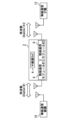
- FIG. 3 is a diagram showing the configuration of a wireless communication system according to Embodiment 1 of the present disclosure.
- the wireless communication system includes a wireless communication repeater 2.
- the wireless communication repeater 2 has a repeater 4, which is, for example, an SOC (System On Chip).
- the repeater 4 relays wireless communication between wireless communication modules 6 and 8, which are wireless communication modules.
- the wireless communication modules 6 and 8 are, for example, NICs (Network Interface Controllers).
- the wireless communication module 6 performs wireless communication with the wireless communication master device 10 .
- the wireless communication module 8 performs wireless communication with a plurality of wireless communication handsets 12.
- FIG. 4 is a diagram showing the configuration of frequency channels according to Embodiment 1 of the present disclosure.
- frequency Channel #1 is used for wireless communication between the wireless communication module 6 and wireless communication base device 10
- frequency Channel #1 is used for wireless communication between the wireless communication module 8 and wireless communication slave device 12. Use 2.
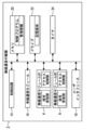
- FIG. 5 is a diagram showing the configuration of a wireless communication repeater according to the present disclosure.
- the wireless communication repeater 2 includes wireless communication modules 6 and 8, as also shown in FIG.
- the wireless communication modules 6 and 8 have a signal receiving section that receives wireless communication, an access control section that performs carrier sense determination on the signal received by the signal receiving section, and a signal transmitting section that transmits wireless communication (not shown). . Further, the wireless communication modules 6 and 8 have adjacent occupied frequencies. Note that although three or more wireless communication modules may be included, this disclosure shows a configuration that includes two wireless communication modules.
- the wireless communication repeater 2 includes a control circuit 14.
- the control circuit 14 controls the observation period and the start timing using management information according to a built-in management program.
- the wireless communication repeater 2 includes a wired communication module 16.
- the wired communication module 16 has a function of performing wired communication, and is used, for example, when performing wired communication with another repeater.
- the wireless communication repeater 2 also includes a user interface 18 .
- the user interface 18 is a module used when changing the settings of the wireless communication repeater 2 from the outside, and is, for example, a controller operated by the user.
- the wireless communication repeater 2 includes a memory 20. Memory 20 has control programs and management information.
- the wireless communication repeater 2 also includes a drive 22 .
- the drive 22 has a storage medium and stores setting information of the repeater and the like.
- the wireless communication repeater 2 includes a timer 24 .
- the timer 24 measures time related to wireless communication of the repeater.
- control unit included in the device of the present disclosure can also be realized by a computer and a program, and the program can be recorded on a recording medium or provided through a network.
- FIG. 6 is a graph showing the range of frequency channels detected by carrier sense according to Embodiment 1 of the present disclosure.
- Channel #1 is the occupied frequency of the wireless communication module 6
- Channel #2 is the occupied frequency of the wireless communication module 8, and as described above, the respective occupied frequencies are adjacent to each other.
- the frequency channel including the adjacent channel is Let the range be the career sense range.
- the wireless communication module 6 sets the range of frequency channels including not only Channel #1 but also adjacent Channel #2 as a carrier sense range.
- carrier sensing can be performed in consideration of adjacent channels affected by leakage power.
- a filter for reception is prepared for each channel. For example, by changing this to a filter that includes all adjacent channels, the above configuration can be realized without complicating the configuration at the time of reception.
- the carrier sense threshold used for threshold determination in the signal receiving section in the wireless communication module may be changed. Since the two wireless communication modules 6 and 8 according to the first embodiment are devices of the same model included in the same wireless communication repeater 2, the power of the signals each receives is also about the same.
- a case will be considered in which the wireless communication module 6 performs carrier sense.
- the wireless communication module 6 performs carrier sense.
- the power leaking from Channel #2 to Channel #1 is lower than the power used by Channel #1 for wireless communication.
- the wireless communication power is low, such as when the wireless communication module 8 starts and ends wireless communication, even if the wireless communication module 6 performs wireless communication, it is unlikely that wireless interference will occur. Become. Based on the above, it is considered that there is no need to refrain from wireless communication of the wireless communication module 6 unless the power consumption of the wireless communication module 8 is sufficiently high.
- the carrier sense threshold for the adjacent channel is set higher than the occupied frequency. Specifically, when carrying out carrier sense in the wireless communication module 6, the carrier sense threshold of Channel #2 is set higher than the carrier sense threshold of Channel #1.
- the determination of the carrier sense result may be changed after referring to the reception state of each wireless communication module. For example, by notifying the transmission failure rate of the wireless communication handset 12, the reception failure rate of the wireless communication module 8 can be detected. Here, if the reception failure rate of the wireless communication module 8 is high, there is a possibility that the leakage power by the wireless communication module 6 is larger than expected and wireless interference is occurring. Therefore, the determination is changed so that the wireless communication of the wireless communication module 6 is stopped. As described above, by changing the determination of the carrier sense result of the wireless communication module 6 based on information such as the reception failure rate of the adjacent wireless communication module, more efficient wireless communication can be performed.
- Embodiment 2 has the same device configuration as Embodiment 1, but differs in that carrier sense is performed only for specific radio signals.
- the BSS identifier such as the BSS color of the signal received on the adjacent channel is also grasped.
- carrier sense determination only signals related to the wireless communication module and the repeater including the wireless communication module are subjected to carrier sense determination. In this way, by making a determination only on wireless signals whose interference should be avoided, it is possible to avoid an event in which wireless communication is excessively restricted.
- FIG. 7 is a diagram showing a frame of a wireless signal according to the second embodiment.
- One method for identifying wireless signals whose interference should be avoided is to use a COLOR field that identifies a BSS (Basic Service Set), which is a wireless LAN cell.
- BSS Basic Service Set
- the value of the COLOR field is used as a simple BSS identifier.
- the carrier sense threshold for this value is set low.
- the same COLOR field value is set for identifiers used by wireless communication modules in the same housing, and the carrier sense threshold is changed when that value is detected.
- the value of the COLOR field used by nearby wireless communication modules is known, and the carrier sense threshold is changed when that value is detected.
- the carrier sense threshold for this value is set high. Since the COLOR field has several types of bits, there is a high probability that different values will be set for terminals outside the wireless communication system. Therefore, for example, the carrier sense threshold is changed for values other than those in the COLOR field that may interfere. As a result, the number of transmission opportunities from the own terminal can be increased, and throughput can be expected to improve.
Landscapes
- Engineering & Computer Science (AREA)
- Computer Networks & Wireless Communication (AREA)
- Signal Processing (AREA)
- Mobile Radio Communication Systems (AREA)
Abstract
この開示は、複数の無線通信モジュール間で通信を行う無線通信装置、無線通信方法及び無線通信システムに関する。本開示の無線通信装置は、信号受信部、アクセス制御部及び信号送信部を有する無線通信モジュールを複数備え、信号受信部が、無線通信信号を受信し、アクセス制御部が、占有周波数のチャネルに加えて隣接チャネルについてキャリアセンスの判定を行い、信号送信部が、判定に基づいて無線送信を行うよう構成されている。
Description
本開示は無線通信装置、無線通信方法及び無線通信システムに係り、複数の無線通信モジュール間で通信を行う無線通信装置、無線通信方法及び無線通信システムに関する。
従来、無線通信の分野では、中継器等を使用して無線信号を中継することで、エリアを拡大する手法が知られている。例えば中継器内に用意した2つの無線通信モジュールが、各々で異なるエリアの端末と通信をする場合、中継器内部で受信したパケットを転送することで2つのエリアの中継が可能となる。
2つの無線通信モジュールを同じ筐体内で使用するためには、無線干渉を回避する必要がある。この回避手段として、周波数による棲み分けが知られている。周波数による棲み分けとしては、例えば十分に離れた周波数チャネルを各無線通信モジュールが使用することで、前述した無線信号の衝突を完全に回避する方法が知られている。
また一般的に、同じエリアで複数の無線通信モジュールが通信を行う場合は、無線送信タイミングが一致することによる無線信号の衝突を回避するため、キャリアセンスを実施する。キャリアセンスとは、自端末から信号を送信する前に、他端末から信号が送信されていないかを、一定時間+ランダム時間の間確認する機能である。この際確認する信号は、自端末で使用する周波数チャネルの範囲に限られている。
IEEE Standard for Information Technology--Telecommunications and Information Exchange between Systems - Local and Metropolitan Area Networks--Specific Requirements - Part 11: Wireless LAN Medium Access Control (MAC) and Physical Layer (PHY) Specifications
しかし、従来の周波数による棲み分けでは、使用可能な周波数チャネル数が少ない場合、十分に周波数が離れているチャネルを用意できない。この場合は例えば、互いに隣接したチャネルを使用することとなる。その際、各無線通信モジュールが自端末の使用するチャネルのみをキャリアセンスして使用すると、隣接チャネルから漏洩した電力によって無線信号の衝突が発生する課題が生じる。
本開示は上述の問題を解決するため、キャリアセンスを実施する周波数チャネルの範囲を隣接チャネルまで広げることで、隣接チャネルを使用する複数の無線通信モジュール同士での信号干渉を回避できる無線通信装置を提供することを第一の目的とする。
本開示の第一の態様は、信号受信部、アクセス制御部及び信号送信部を有する無線通信モジュールを複数備え、信号受信部が、無線通信信号を受信し、アクセス制御部が、占有周波数のチャネルに加えて隣接チャネルについてキャリアセンスの判定を行い、信号送信部が、判定に基づいて無線送信を行う無線通信装置であることが好ましい。
本開示の第二の態様は、複数の無線通信モジュールが、無線通信信号を受信する受信処理と、占有周波数のチャネルに加えて隣接チャネルについてキャリアセンスの判定を行う判定処理と、判定処理の結果に基づいて無線通信を行う送信処理とを備える無線通信方法であることが好ましい。
本開示の第三の態様は、無線通信信号を受信する信号受信部と、占有周波数のチャネルに加えて隣接チャネルについてキャリアセンスの判定を行うアクセス制御部と、判定に基づいて無線通信を実施または中止する信号送信部とを複数備える無線通信システムであることが好ましい。
本開示の第一から第三の態様によれば、キャリアセンスを実施する周波数範囲を隣接チャネルまで広げることで、隣接チャネルを使用する複数の無線通信モジュール同士での信号干渉を回避できる無線通信装置、無線通信方法及び無線通信システムの提供が可能となる。
実施の形態1
実施の形態1の説明に先立ち、複数の無線通信モジュールで通信を行う際、従来の方法で生じていた課題について述べる。図1は、無線信号スペクトルの送信スペクトルマスクを示すグラフである。ここでは、IEEE 802.11ah 1MHz帯既定の送信スペクトルマスクを示している。
実施の形態1の説明に先立ち、複数の無線通信モジュールで通信を行う際、従来の方法で生じていた課題について述べる。図1は、無線信号スペクトルの送信スペクトルマスクを示すグラフである。ここでは、IEEE 802.11ah 1MHz帯既定の送信スペクトルマスクを示している。
図1のグラフより、中心周波数から0.6MHz離れた周波数でも、パワースペクトル密度が-20dBr(decibels relative to reference level)となる場合があると分かる。例えばメインローブの信号電力密度が3dBm/100kHzの場合、中心から600kHz離れた周波数位置では-17dBm/100kHzとなる。
ここで無線空間での減衰は、例えば20dB以下であれば十分と言える。つまり、1MHz幅チャネルの送信スペクトルでは、中心周波数から0.5MHz以上離れたチャネル範囲外の周波数でも、減衰が不十分とみなされる。そのため、この信号を極近傍で受信する場合は減衰が不十分であり、漏洩電力だけでも大きな干渉となる。つまり、無線干渉の回避のため周波数による棲み分けをする場合、隣接する周波数チャネルでは十分に役割を果たせない場合があることが分かる。
図2は、中継器で観測される受信強度の例を示すグラフである。ここでは、中継器が備える二つの無線通信モジュールが使用する周波数チャネルとその電力強度を示している。Channel#1は無線通信モジュール#1が使用する周波数チャネルであり、Channel#2は無線通信モジュール#2が使用する周波数チャネルである。またChannel#1とChannel#2は、隣接する周波数チャネルである。
例えば、無線通信モジュール#2がChannel#2で信号受信をしている際に、無線通信モジュール#1がChannel#1を使用して信号送信を開始する場合を考える。従来方式では、無線通信モジュール#1のキャリアセンスは、Channel#1の範囲でのみ信号を検出する。そのため無線通信モジュール#1は、Channel#2からChannel#1に漏洩した電力のみを検出し、キャリアセンス結果を判定する。このとき、Channel#2から漏洩した電力がキャリアセンス閾値よりも低ければ、無線通信モジュール#2はアイドル状態と判定される。そのため無線通信モジュール#1は、Channel#1を使用した信号送信を開始する。
しかし、実際には無線通信モジュール#2はChannel#2の信号を受信中である。ここで無線通信モジュール#1が信号送信を開始すると、Channel#1からChannel#2に電力が漏洩する。この漏洩電力からの干渉により、無線通信モジュール#2がChannel#2で受信している信号に復調誤りが発生するため、信号の受信に失敗してしまう。
以上のように、隣接する周波数チャネルを用いる場合、無線干渉の回避が難しい場合がある。また、2つの無線通信モジュールが異なる周波数チャネルを使用する他の例として、中継器の通信する各エリアで干渉状況が異なることから、最適な周波数チャネルが異なる場合が挙げられる。しかし、その最適な周波数チャネル同士が隣接する場合は、図2の場合と同様の問題が発生し得る。
本開示では、中継器内、または非常に近接した場所に設置された無線機で隣接チャネルを使用する場合、キャリアセンスする周波数範囲を隣接チャネルまで広げる。それにより、隣接チャネルを使用する複数の無線通信モジュール同士での信号干渉を回避する。
これより、実施の形態1について説明する。図3は、本開示の実施の形態1に係る無線通信システムの構成を示す図である。無線通信システムは、無線通信中継器2を備える。無線通信中継器2は中継器4を有し、これは例えばSOC(System On Chip)である。中継器4は無線通信モジュールである無線通信モジュール6及び8の間で無線通信を中継する。無線通信モジュール6及び8は例えばNIC(Network Interface Controller)である。無線通信モジュール6は、無線通信親機10と無線通信を行う。また無線通信モジュール8は、複数の無線通信子機12と無線通信を行う。
図4は、本開示の実施の形態1に係る周波数チャネルの構成を示す図である。実施の形態1に係る無線通信システムでは、無線通信モジュール6と無線通信親機10の無線通信には周波数Channel#1を、無線通信モジュール8と無線通信子機12の無線通信には周波数Channel#2を使用する。
図5は、本開示の無線通信中継器の構成を示す図である。無線通信中継器2は、図3でも示した通り、無線通信モジュール6及び8を備える。無線通信モジュール6及び8は、無線通信を受信する信号受信部と、信号受信部で受信した信号についてキャリアセンスの判定を行うアクセス制御部と、図示しないが無線通信を送信する信号送信部を有する。また無線通信モジュール6及び8は、双方の占有周波数が隣接している。なお、無線通信モジュールは3つ以上含まれていても良いが、本開示では2つ含まれる構成を示す。
無線通信中継器2は制御回路14を備える。制御回路14は、内蔵する管理プログラムに従い、管理情報を用いた観測期間の制御や開始タイミングの制御を行う。
無線通信中継器2は有線通信モジュール16を備える。有線通信モジュール16は有線通信を行う機能を有し、例えば他の中継器と有線通信を行う際に用いる。また無線通信中継器2は、ユーザインタフェース18を備える。ユーザインタフェース18は、無線通信中継器2の設定変更を外部から行う際に用いるモジュールであり、例えばユーザが操作するコントローラである。
無線通信中継器2は、メモリ20を備える。メモリ20は制御プログラム及び管理情報を有する。また無線通信中継器2は、ドライブ22を備える。ドライブ22は記憶媒体を有し、中継器の設定情報等を記憶する。更に無線通信中継器2は、タイマ24を備える。タイマ24は、中継器の無線通信に係る時間計測などを行う。
なお、本開示の装置が備える制御部はコンピュータとプログラムによっても実現でき、プログラムを記録媒体に記録することも、ネットワークを通して提供することも可能である。
図6は、本開示の実施の形態1に係るキャリアセンスで検出する周波数チャネルの範囲を示すグラフである。Channel#1は無線通信モジュール6の占有周波数、Channel#2は無線通信モジュール8の占有周波数であり、前述した通りそれぞれの占有周波数は隣接している。
本開示に係るキャリアセンスでは、同一筐体またはごく近傍に設置された端末が隣接チャネルを使用する場合、送信する対象となるチャネルである占有周波数に加えて、その隣接チャネルも含めた周波数チャネルの範囲をキャリアセンス範囲とする。無線通信中継器2では、無線通信モジュール6が、Channel#1に加えて、隣接するChannel#2も含めた周波数チャネルの範囲をキャリアセンス範囲とする。
キャリアセンスを実施する周波数範囲を広げることで、漏洩電力が影響する隣接チャネルを考慮したキャリアセンスが可能となる。その結果、隣接チャネルを使用する複数の無線通信モジュール同士での信号干渉を回避でき、更にスループット改善も可能とする無線通信装置の提供が可能となる。
なお、従来例では受信時のフィルタをチャネルごとに用意している。例えばこれを、隣接チャネルを全て包含するフィルタに変更することで、受信時の構成を複雑にすることなく上述の構成を実現できる。
また隣接チャネルについては、無線通信モジュール内の信号受信部での閾値判定に用いるキャリアセンス閾値を変更しても良い。実施の形態1に係る2つの無線通信モジュール6及び8は、同じ無線通信中継器2に含まれる同じ機種の装置であることから、それぞれが受信する信号の電力も同程度となる。ここで、無線通信モジュール6でキャリアセンスを実施する場合を考える。無線通信モジュール8で無線通信が行われている場合、Channel#2からChannel#1に漏洩する電力は、Channel#1が無線通信で使用する電力よりも低くなることが想定される。つまり、無線通信モジュール8での無線通信開始時及び終了直前のように、通信電力が低い期間であれば、無線通信モジュール6が無線通信を行ったとしても、無線干渉が発生する可能性は低くなる。以上により、無線通信モジュール8の使用電力が十分に高い場合でなければ、無線通信モジュール6の無線通信を控える必要はないと考えられる。
そのため例えば、隣接チャネルについてのキャリアセンス閾値を、占有周波数と比較して高く設定する。具体的には、無線通信モジュール6でキャリアセンスを実施する場合は、Channel#2のキャリアセンス閾値を、Channel#1のキャリアセンス閾値より高く設定する。こうして隣接チャネルにおけるキャリアセンスの感度を下げることで、必要以上に無線送信を控えることなく、効率の良い無線通信を行うことができるようになる。
あるいは、無線通信システム外の無関係な無線通信モジュールが、隣接チャネルを用いた無線通信を近傍で行っている場合を考える。この無線通信モジュールからの電波は、電力強度が高ければ無線干渉を引き起こす可能性があるが、同じ中継器内部の無線通信モジュールと比較すると影響は小さいと想定される。そのため、この隣接チャネルについてはキャリアセンス閾値を高く設定し、キャリアセンスの感度を下げることで、効率の良い無線通信を行うことができるようになる。
さらに、各無線通信モジュールの受信状態などを参照した上で、キャリアセンス結果の判定を変更しても良い。例えば、無線通信子機12の送信失敗率を通知させることで、無線通信モジュール8の受信失敗率を検知することができる。ここで、無線通信モジュール8の受信失敗率が高い場合、無線通信モジュール6による漏洩電力が想定よりも大きく、無線干渉が発生している可能性が考えられる。そこで、無線通信モジュール6の無線通信を止めるように判定を変更する。以上のように、隣接する無線通信モジュールの受信失敗率のような情報に基づき、無線通信モジュール6のキャリアセンス結果の判定を変更することで、より効率的な無線通信を行うことができる。
実施の形態2
実施の形態2は、実施の形態1と装置構成等は同様であるが、特定の無線信号に対してのみキャリアセンスを行う点が異なる。例えば、隣接チャネルで受信された信号のBSS color等のBSS識別子も把握する。それにより、無線通信モジュール及びそれを含む中継器等に関係ある信号のみを、キャリアセンスでの判定の対象とする。こうして、干渉を回避するべき無線信号のみに対して判定を行うことで、過剰に無線通信の規制を行ってしまう事象を回避することができる。
実施の形態2は、実施の形態1と装置構成等は同様であるが、特定の無線信号に対してのみキャリアセンスを行う点が異なる。例えば、隣接チャネルで受信された信号のBSS color等のBSS識別子も把握する。それにより、無線通信モジュール及びそれを含む中継器等に関係ある信号のみを、キャリアセンスでの判定の対象とする。こうして、干渉を回避するべき無線信号のみに対して判定を行うことで、過剰に無線通信の規制を行ってしまう事象を回避することができる。
図7は、実施の形態2に係る無線信号のフレームを示す図である。干渉を回避すべき無線信号を識別する方法として、無線LANのセルであるBSS(Basic Service Set)を識別するCOLORフィールドを使用する方法が挙げられる。COLORフィールドの値は、簡易的なBSSの識別子として使用されるものである。
受信した信号のCOLORフィールドが干渉を回避すべき値である場合は、この値に対するキャリアセンス閾値を低く設定する。例えば、同一筐体の無線通信モジュールが使用する識別子に同じCOLORフィールドの値を設定し、その値を検知した際にキャリアセンス閾値を変更する。あるいは、近傍の無線通信モジュールが使用するCOLORフィールドの値を把握しておき、その値を検知した際にキャリアセンス閾値を変更する。その結果、干渉を起こしやすい無線通信の同時発生を抑制できるため、干渉を回避しやすくなる。
また、受信した信号のCOLORフィールドが干渉を回避すべき値でない場合は、この値に対するキャリアセンス閾値を高く設定する。COLORフィールドには数ビット分の種類があるため、無線通信システム外の端末であれば、高確率で異なる値が設定されている。そこで例えば、干渉し得るCOLORフィールドの値以外は、キャリアセンス閾値を変更する。その結果、自端末からの送信機会を増やせるため、スループット向上が期待できるようになる。
6 無線通信モジュール
8 無線通信モジュール
8 無線通信モジュール
Claims (7)
- 信号受信部、アクセス制御部及び信号送信部を有する無線通信モジュールを複数備え、
前記信号受信部が、無線通信信号を受信し、
前記アクセス制御部が、占有周波数のチャネルに加えて隣接チャネルについてキャリアセンスの判定を行い、
前記信号送信部が、前記判定に基づいて無線送信を行う
無線通信装置。 - 前記アクセス制御部が、
キャリアセンス閾値を、占有周波数のチャネルとその隣接チャネルで変更する
請求項1に記載の無線通信装置。 - 前記アクセス制御部が、
他の無線通信モジュールの受信状態を検知し、
前記受信状態に基づいて、前記判定を変更する
請求項1に記載の無線通信装置。 - 前記無線通信信号が、COLORフィールドを有し、
前記アクセス制御部が、前記COLORフィールドの値に基づいてキャリアセンス閾値を変更する
請求項1に記載の無線通信装置。 - 前記無線通信モジュールが、占有周波数のチャネル及びその隣接チャネルを包含する受信フィルタを有する
請求項1に記載の無線通信装置。 - 複数の無線通信モジュールが、
無線通信信号を受信する受信処理と、
占有周波数のチャネルに加えて隣接チャネルについてキャリアセンスの判定を行う判定処理と、
前記判定処理の結果に基づいて無線通信を行う送信処理と
を備える無線通信方法。 - 無線通信信号を受信する信号受信部と、
占有周波数のチャネルに加えて隣接チャネルについてキャリアセンスの判定を行うアクセス制御部と、
前記判定に基づいて無線通信を実施または中止する信号送信部と、
を複数備える無線通信システム。
Priority Applications (1)
| Application Number | Priority Date | Filing Date | Title |
|---|---|---|---|
| PCT/JP2022/017871 WO2023199491A1 (ja) | 2022-04-14 | 2022-04-14 | 無線通信装置、無線通信方法及び無線通信システム |
Applications Claiming Priority (1)
| Application Number | Priority Date | Filing Date | Title |
|---|---|---|---|
| PCT/JP2022/017871 WO2023199491A1 (ja) | 2022-04-14 | 2022-04-14 | 無線通信装置、無線通信方法及び無線通信システム |
Publications (1)
| Publication Number | Publication Date |
|---|---|
| WO2023199491A1 true WO2023199491A1 (ja) | 2023-10-19 |
Family
ID=88329408
Family Applications (1)
| Application Number | Title | Priority Date | Filing Date |
|---|---|---|---|
| PCT/JP2022/017871 WO2023199491A1 (ja) | 2022-04-14 | 2022-04-14 | 無線通信装置、無線通信方法及び無線通信システム |
Country Status (1)
| Country | Link |
|---|---|
| WO (1) | WO2023199491A1 (ja) |
Citations (4)
| Publication number | Priority date | Publication date | Assignee | Title |
|---|---|---|---|---|
| JP2017098676A (ja) * | 2015-11-19 | 2017-06-01 | キヤノン株式会社 | 制御装置、制御方法、およびプログラム |
| JP2018527840A (ja) * | 2015-09-15 | 2018-09-20 | クゥアルコム・インコーポレイテッドQualcomm Incorporated | 近隣の通信ネットワークにおけるワイヤレス通信リソースの再利用のためのシステムおよび方法 |
| JP2021019242A (ja) * | 2019-07-18 | 2021-02-15 | コニカミノルタ株式会社 | 情報処理装置及びプログラム |
| WO2022049666A1 (ja) * | 2020-09-02 | 2022-03-10 | 日本電信電話株式会社 | 無線通信方法及び無線通信装置 |
-
2022
- 2022-04-14 WO PCT/JP2022/017871 patent/WO2023199491A1/ja unknown
Patent Citations (4)
| Publication number | Priority date | Publication date | Assignee | Title |
|---|---|---|---|---|
| JP2018527840A (ja) * | 2015-09-15 | 2018-09-20 | クゥアルコム・インコーポレイテッドQualcomm Incorporated | 近隣の通信ネットワークにおけるワイヤレス通信リソースの再利用のためのシステムおよび方法 |
| JP2017098676A (ja) * | 2015-11-19 | 2017-06-01 | キヤノン株式会社 | 制御装置、制御方法、およびプログラム |
| JP2021019242A (ja) * | 2019-07-18 | 2021-02-15 | コニカミノルタ株式会社 | 情報処理装置及びプログラム |
| WO2022049666A1 (ja) * | 2020-09-02 | 2022-03-10 | 日本電信電話株式会社 | 無線通信方法及び無線通信装置 |
Similar Documents
| Publication | Publication Date | Title |
|---|---|---|
| US10623125B2 (en) | Resource utilization for uplink transmission based on indicated interference | |
| US8886203B2 (en) | Dynamic channel reuse in multi-access communication systems | |
| EP3536005B1 (en) | Cooperation between nodes operating in licensed and unlicensed spectrum for channel access in unlicensed spectrum | |
| US8155032B2 (en) | Adaptive scheduling for half-duplex wireless terminals | |
| KR101131750B1 (ko) | 단일 전자 디바이스 내에 공동배치된 다수의 무선 통신 프로토콜에 대한 통신의 조정 | |
| TWI477090B (zh) | 協調多重無線收發器之裝置及方法 | |
| US9788363B2 (en) | LTE and WLAN/bluetooth coexistence | |
| EP2001176A2 (en) | Method for configuring multi-channel communication | |
| KR20130093659A (ko) | 무선 통신 시스템, 통신 유닛 및 스케줄링 방법 | |
| TW201212559A (en) | Method and wireless communication device to trigger in-device coexistence interference mitigation | |
| KR101217966B1 (ko) | 조정되지 않은 시간 분할 듀플렉스 통신 네트워크들 간의 동기화 | |
| US9220102B2 (en) | Low power base station and communication control method | |
| WO2012064093A2 (en) | Method and apparatus of handling in-device co-existence interference in a multi-radio environment | |
| US8620312B2 (en) | Combined background and 20/40 coexistence scan | |
| EP3203794B1 (en) | Coexistence of lte and other systems | |
| JP2017135699A (ja) | 同じ周波数帯域の2つの無線周波数モジュールをもつワイヤレスアクセスポイントおよび信号干渉低減方法 | |
| CN116250291A (zh) | 一种通信方法及装置 | |
| WO2023199491A1 (ja) | 無線通信装置、無線通信方法及び無線通信システム | |
| Verma et al. | Throughput enhancement to the cognitive radio networks under the precaution based cooperation of the primary users | |
| CN114270987A (zh) | 用于功率节省的传输检测跳过机制 | |
| WO2023199480A1 (ja) | 無線通信装置、無線通信方法及び無線通信システム | |
| CN114731613A (zh) | 位置感知空间重用 | |
| Luís et al. | A double-stage reservation-based MAC scheme for distributed cognitive radio networks |
Legal Events
| Date | Code | Title | Description |
|---|---|---|---|
| 121 | Ep: the epo has been informed by wipo that ep was designated in this application |
Ref document number: 22937470 Country of ref document: EP Kind code of ref document: A1 |