WO2023199471A1 - 散水装置 - Google Patents
散水装置 Download PDFInfo
- Publication number
- WO2023199471A1 WO2023199471A1 PCT/JP2022/017806 JP2022017806W WO2023199471A1 WO 2023199471 A1 WO2023199471 A1 WO 2023199471A1 JP 2022017806 W JP2022017806 W JP 2022017806W WO 2023199471 A1 WO2023199471 A1 WO 2023199471A1
- Authority
- WO
- WIPO (PCT)
- Prior art keywords
- windbreak
- cut
- plate
- right direction
- outdoor unit
- Prior art date
- Legal status (The legal status is an assumption and is not a legal conclusion. Google has not performed a legal analysis and makes no representation as to the accuracy of the status listed.)
- Ceased
Links
Images







Classifications
-
- F—MECHANICAL ENGINEERING; LIGHTING; HEATING; WEAPONS; BLASTING
- F24—HEATING; RANGES; VENTILATING
- F24F—AIR-CONDITIONING; AIR-HUMIDIFICATION; VENTILATION; USE OF AIR CURRENTS FOR SCREENING
- F24F1/00—Room units for air-conditioning, e.g. separate or self-contained units or units receiving primary air from a central station
- F24F1/06—Separate outdoor units, e.g. outdoor unit to be linked to a separate room comprising a compressor and a heat exchanger
- F24F1/46—Component arrangements in separate outdoor units
Definitions
- the present disclosure relates to a water sprinkler, and more particularly, to a water sprinkler that cools an outdoor unit installed in an air conditioner.
- An air conditioner (so-called indoor air conditioner) installed indoors, such as in a living room or in a store, includes an indoor unit and an outdoor unit.
- the indoor unit and the outdoor unit are connected via piping for refrigerant circulation. Since the outdoor unit is installed outdoors, the main body of the outdoor unit and the surrounding area of the outdoor unit become hot during high temperatures such as in summer.
- the outdoor unit is equipped with a heat exchanger that exchanges heat between the outside air and the refrigerant.
- the heat exchanger mounted on the outdoor unit functions as a condenser when the air conditioner is performing cooling operation. At high temperatures, the heat exchange efficiency of the heat exchanger decreases, the cooling capacity of the air conditioner decreases, the load on the air conditioner increases, and power consumption increases. Therefore, there is a need to improve the heat exchange efficiency by cooling the outdoor unit.
- One technique to improve the energy-saving performance of air conditioners is to sprinkle water on the heat exchanger installed in the outdoor unit.
- Patent Document 1 discloses that a type 1 nozzle and a type 2 nozzle are provided at a position away from the heat exchanger in order to cool the heat exchanger by spraying water from the nozzle. There is.
- the first type nozzle injects water when the air conditioner starts operating, wets the heat exchanger, and then stops.
- the second type nozzle sprays droplets having a finer particle shape than the first type nozzle. Therefore, the spray emitted from the second type nozzle is vaporized before it adheres to the heat exchanger. As a result, the heat exchanger is supplied with highly humid air.
- the second type nozzle performs jetting intermittently after the first type nozzle stops jetting. Further, in Patent Document 1, a light shielding cover surrounding an air intake port provided in a case of an outdoor unit is attached.
- Patent Document 1 by covering the intake port of the outdoor unit with a light-shielding cover, the heat exchanger is prevented from overheating due to direct sunlight, and the temperature of the intake air taken into the outdoor unit from the intake port is reduced.
- the outdoor unit is efficiently cooled by combining these effects of the light shielding cover with cooling of the heat exchanger itself by spraying from the nozzle.
- a water spray nozzle is installed at a location away from the heat exchanger, such as the type 1 nozzle and type 2 nozzle described in Patent Document 1, to reduce the heat exchanger's energy consumption. Sprinkling water over a wide area is effective. However, if the droplets are atomized or the nozzle is moved away from the condenser, the sprayed droplets become more susceptible to external disturbances such as crosswinds, resulting in the problem of not being able to spray water on the intended areas of the heat exchanger due to external disturbances. occurs.
- a cover is attached to cover the intake port of the outdoor unit.
- the cover has a substantially inverted L-shaped cross section and a box-like shape with only the lower end open.
- the front wall of the cover is arranged to face the intake port of the outdoor unit, and has a plurality of ventilation holes. Air that has passed through a ventilation hole provided in the front wall of the cover is supplied to the intake port of the outdoor unit.
- the cover described in Patent Document 1 since the cover described in Patent Document 1 has a structure that prevents air intake from the air intake port, it is easily assumed that the cover described in Patent Document 1 significantly reduces the air intake amount of the outdoor unit.
- the present disclosure has been made in order to solve such problems, and it is possible to sprinkle water on the intended location of the outdoor unit without sacrificing air intake to the outdoor unit and without being affected by crosswinds.
- the purpose is to provide watering equipment.
- the watering device includes a windbreak plate attached to at least one side in the left and right direction of a first side face portion provided with an air intake port among four side faces of a housing of an outdoor unit; a nozzle attached to a board, protruding inward in the left-right direction in a direction intersecting with the windbreak board, and spraying water inward in the left-right direction; and a nozzle formed on the windbreak board, the nozzle being formed on the windbreak board; a cut-and-raised portion having an opening that penetrates through the thickness, and the windbreak plate extends in a direction intersecting the first side surface of the housing and is separated from the first side surface of the housing.
- the cut-and-raised portion is arranged to be inclined toward the intake port, and the airflow passing through the opening of the cut-and-raised portion flows along the cut-and-raised portion and reaches the intake port. Air is blown towards the area.
- the windbreak plate by providing the windbreak plate, it is possible to prevent disturbance to the air flow caused by crosswinds around the heat exchanger, so water can be sprinkled on desired locations of the heat exchanger. Furthermore, by providing the windshield plate with the cut-and-raised portion, a portion of the crosswind can be collected toward the heat exchanger, so that the amount of air that cools the heat exchanger can be increased. Therefore, by sprinkling water to the intended location of the outdoor unit without sacrificing air intake to the outdoor unit or being affected by crosswinds, the energy-saving effect of the outdoor unit can be improved, a remarkable and unprecedented effect. It is something that plays.
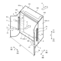
- FIG. 1 is a perspective view showing the configuration of a water sprinkler device 1 that assists in cooling a heat exchanger 103 installed in an outdoor unit 100 of an air conditioner according to a first embodiment.
- 1 is a sectional view showing the configuration of an outdoor unit 100 and a water sprinkler 1 according to Embodiment 1.
- FIG. 1 is a plan view showing the configuration of an outdoor unit 100 and a water sprinkler 1 according to Embodiment 1.
- FIG. 1 is a configuration diagram showing a configuration of a water supply system of a water sprinkler 1 according to Embodiment 1.
- FIG. FIG. 3 is an enlarged plan view showing the configuration of a cut-and-raised portion 5 provided in the water sprinkler 1 according to the first embodiment.
- FIG. 2 is a plan view showing the configuration of an outdoor unit 100 and a water sprinkler 1 according to a second embodiment. It is a perspective view showing composition of outdoor unit 100 and water sprinkler 1 concerning Embodiment 3.
- FIG. 3 is a plan view showing the configurations of an outdoor unit 100 and a water sprinkler 1 according to a fourth embodiment. It is a top view which shows the structure of the outdoor unit 100 and the water sprinkler 1 based on Embodiment 5. It is a sectional view showing composition of outdoor unit 100 and water sprinkler 1 concerning Embodiment 5.
- 12 is a plan view showing the configuration of an outdoor unit 100 and a water sprinkler 1 according to a first modification of the fifth embodiment.
- FIG. 7 is a plan view showing the configuration of an outdoor unit 100 and a water sprinkler 1 according to a second modification of the fifth embodiment.
- FIG. 7 is a plan view showing the configuration of an outdoor unit 100 and a water sprinkler 1 according to a third modification of the fifth embodiment.
- FIG. 7 is a plan view showing the configuration of an outdoor unit 100 and a water sprinkler 1 according to a fourth modification of the fifth embodiment. It is a perspective view showing composition of outdoor unit 100 and water sprinkler 1 concerning Embodiment 6. It is a back view which shows the structure of 5 A of 2nd cut-and-raised parts provided in the water sprinkler 1 based on Embodiment 6.
- FIG. 7 is a side view showing the configuration of a third cut-and-raised portion 5B provided in the water sprinkler 1 according to Modification 1 of Embodiment 6.
- FIG. 7 is a perspective view showing the configuration of a third cut-and-raised portion 5B provided in the water sprinkler 1 according to Modification 1 of Embodiment 6.
- FIG. 7 is a side view showing the configuration of a third cut-and-raised portion 5B provided in the water sprinkler 1 according to a second modification of the sixth embodiment. It is a back view which shows the structure of 5 A of 2nd cut-and-raised parts, and the 3rd cut-and-raised part 5B provided in the water sprinkler 1 based on the modification 3 of Embodiment 6.
- FIG. 7 is a side view showing the configuration of a second cut-and-raised portion 5A and a third cut-and-raised portion 5B provided in the water sprinkler 1 according to a third modification of the sixth embodiment.
- the Z direction indicates the vertical direction of the outdoor unit 100, and is, for example, the vertical direction.
- the X direction indicates the width direction of the outdoor unit 100, and is a direction intersecting the Z direction.
- the Y direction indicates the depth direction of the outdoor unit 100, and is a direction that intersects the Z direction and the X direction.
- the X direction and the Y direction are, for example, horizontal directions.
- FIG. 1 is a perspective view showing the configuration of a water sprinkler 1 that assists in cooling a heat exchanger 103 installed in an outdoor unit 100 of an air conditioner according to a first embodiment.
- FIG. 2 is a cross-sectional view showing the configuration of the outdoor unit 100 and the water sprinkler 1 according to the first embodiment.
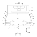
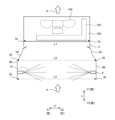
- FIG. 3 is a plan view showing the configurations of the outdoor unit 100 and the water sprinkler 1 according to the first embodiment.
- FIG. 4 is a configuration diagram showing the configuration of the water supply system of the water sprinkler 1 according to the first embodiment.
- FIG. 5 is an enlarged plan view showing the configuration of the cut-and-raised portion 5 provided in the water sprinkler 1 according to the first embodiment.
- FIG. 5 shows the structure of the cut-and-raised portion 5 provided on the left windbreak plate 3, and (b) shows the structure of the cut-and-raised portion 5 provided on the right-side windbreak plate 3.
- FIGS. 2 and 5 show the state viewed from above in the Z direction.
- the water sprinkler 1 is used by being attached to an outdoor unit 100 of an air conditioner, as shown in FIGS. 1 to 3. Before explaining the configuration of the water sprinkler 1, the configuration of the outdoor unit 100 will be explained first.
- the outdoor unit 100 has a casing 101 that constitutes an outer shell of the outdoor unit 100, as shown in FIG.
- the housing 101 or the outdoor unit 100 has, for example, a box-like shape as a whole.
- the housing 101 has an upper surface portion 101a and four side surfaces 101b.
- the side portions 101b constitute four side surfaces of the outdoor unit 100.
- the four side surfaces 101b of the housing 101 may be composed of side panels, but it is not necessary to arrange side panels on all of the four side surfaces 101b; The arrangement of the side panels may be omitted.
- An intake port 102 is provided in at least one of the side surfaces 101b.
- the intake ports 102 may be provided in two or three of the four side surfaces 101b.
- the intake port 102 is provided on only one side surface portion 101b.
- the side surface portion 101b provided with the intake port 102 will be referred to as a first side surface portion 101b-1.
- the first side surface portion 101b-1 is sometimes called the back surface of the outdoor unit 100.
- an exhaust port 105 is provided in the other side surface portion 101b in which the intake port 102 is not provided.
- the side surface portion 101b provided with the exhaust port 105 will be referred to as a second side surface portion 101b-2.
- the second side surface portion 101b-2 is sometimes called the front surface of the outdoor unit 100.
- the first side surface portion 101b-1 and the second side surface portion 101b-2 are opposed to each other. Furthermore, the side surface portion disposed between the first side surface portion 101b-1 and the second side surface portion 101b-2 will be referred to as a third side surface portion 101b-3. Air supplied into the housing 101 from the intake port 102 is exhausted to the outside of the housing 101 from the exhaust port 105.
- a heat exchanger 103 and a blower 104 are housed inside the casing 101 of the outdoor unit 100. Inside the casing 101 of the outdoor unit 100, other devices such as a compressor 122 (see FIG. 8) are also housed.
- the blower 104 includes a motor 104a and a blade section 104b.
- the axial direction of the motor 104a extends in the Y direction.
- the blower 104 is placed opposite the heat exchanger 103. More specifically, the blower 104 is arranged to face a portion of the heat exchanger 103 that extends in the X direction.
- the blower 104 supplies air to the heat exchanger 103 by blowing air toward the heat exchanger 103.
- the blower 104 is arranged to face the air intake port 102 provided in the first side surface portion 101b-1, with the heat exchanger 103 interposed therebetween. Therefore, the blower 104 is disposed closer to the second side surface portion 101b-2 than the heat exchanger 103.
- the heat exchanger 103 includes a plurality of refrigerant pipes 103a and a plurality of fins 103b.
- the heat exchanger 103 is, for example, a fin-and-tube heat exchanger.
- the heat exchanger 103 has an L-shape in plan view.
- the refrigerant pipe 103a is also called a heat transfer tube.
- the refrigerant pipe 103a is bent into an L-shape along the L-shape of the heat exchanger 103.
- the refrigerant pipe 103a extends from one end (hereinafter referred to as a first end 103c) of the heat exchanger 103 to the other end (hereinafter referred to as a second end 103d).
- the direction in which the refrigerant pipe 103a extends will be referred to as the "pipe axis direction.” Therefore, the direction of the tube axis changes at one point in the middle of the refrigerant pipe 103a (hereinafter referred to as a bent portion 103e). Specifically, the tube axis direction extends in the X direction from the first end 103c to the bent portion 103e, and then extends toward the leeward side in the Y direction from the bent portion 103e to the second end 103d. In this way, the heat exchanger 103 is bent at the second end 103d side and has an L-shape in plan view. Therefore, the second end 103d side is sometimes referred to as the "bent side.” On the other hand, the first end 103c side is sometimes referred to as the "unbent side.”
- the fin 103b has a plate-like shape.
- the fins 103b are spaced apart from each other in the tube axis direction.
- the refrigerant pipe 103a is arranged to penetrate the fins 103b.
- the refrigerant pipes 103a are arranged at intervals in the Z direction.
- the refrigerant pipes 103a may be arranged in one row in the Z direction, but may also be arranged in two rows as shown in FIG.
- each row of refrigerant pipes 103a is arranged at intervals in the Y direction.
- the refrigerant pipe 103a is configured from a circular tube, but the refrigerant piping 103a is not limited to that case, and may be configured from a flat tube.
- the heat exchanger 103 exchanges heat between the refrigerant flowing inside the refrigerant pipe 103a and the air supplied by the blower 104.
- the heat exchanger 103 functions as a condenser and condenses and liquefies the refrigerant when the air conditioner is performing cooling operation.
- the heat exchanger 103 functions as an evaporator and evaporates the refrigerant.
- the watering device 1 includes two windbreak plates 3, a nozzle mounting hole 4, a cut-and-raised portion 5, and a nozzle 6.
- the water sprinkler 1 further includes a water supply pipe 41 that supplies cooling water to the nozzle 6 and a control unit 44 that controls water supply to the nozzle 6, as shown in FIG.
- the two windbreak plates 3 are attached to the intake port 102 side provided on the first side surface portion 101b-1 of the casing 101 of the outdoor unit 100.
- the two windbreak plates 3 are provided at both ends of the first side surface portion 101b-1 in the X direction.
- the windbreak plate 3 protrudes from both ends of the first side surface portion 101b-1 in the X direction in a direction intersecting the first side surface portion 101b-1.
- the windbreak plate 3 protrudes toward the rear side in the Y direction. That is, the windbreak plate 3 protrudes from the first side surface portion 101b-1 in a direction away from the casing 101 of the outdoor unit 100.
- the two windbreak plates 3 are arranged to face each other.
- the space between the two windbreak plates 3 is sometimes referred to as the "inner side in the left-right direction.”
- the windbreak plate 3 has a vertically long flat plate shape.
- the two windbreak plates 3 may have the same type and size, or may have different shapes or sizes.
- the windbreak plate 3 has a first end 3a, which is one side in the longitudinal direction, fixed to an end in the X direction of the first side surface 101b-1.
- the windbreak plate 3 is fixed in a cantilevered manner. Therefore, the second end 3b, which is the other longitudinal side of the windbreak plate 3, is a free end.
- the first end portions 3a of the left and right windbreak plates 3 and the first side surface portion 101b-1 of the housing 101 are fixed by, for example, welding or a jig.
- the first end 3a and the second end 3b both extend in the Z direction and are arranged to face each other.
- the windbreak plate 3 is arranged in line with the third side surface portion 101b-3 of the housing 101 in a straight line in the Y direction.
- the windbreak plate 3 is arranged parallel to the YZ plane.
- the windbreak plate 3 blocks crosswinds 13, as shown in FIG.
- the cross wind 13 is wind that blows in a direction substantially perpendicular to the left and right third side surfaces 101b-3 of the outdoor unit 100.
- the windbreak plate 3 is made of, for example, a metal such as aluminum or steel, or a resin with excellent weather resistance such as polyvinyl chloride (PVC).
- PVC polyvinyl chloride
- the material of the windbreak plate 3 is not limited to these examples.
- the nozzle mounting hole 4 is provided in the windshield plate 3.
- the nozzle attachment hole 4 is a hole into which the nozzle 6 is attached.
- the nozzle attachment hole 4 is, for example, a circular through hole that penetrates the thickness of the windshield plate 3.
- two nozzle mounting holes 4 are provided for each windshield plate 3. These two nozzle attachment holes 4 are arranged side by side in the Z direction.
- the total number of nozzle attachment holes 4 is four, but the number is not limited to this and may be any number.
- the cut-and-raised portion 5 is provided on the windbreak plate 3 so that the opening 5a faces the intake port 102 side of the outdoor unit 100.
- the cut and raised portion 5 is arranged downstream of the nozzle attachment hole 4 in the air flow direction shown by arrow A in FIG.
- the cut-and-raised portion 5 is formed by, for example, a cut-and-raised process. Cut-and-raise processing is a technique in which a cut is made around the part you want to bend, a mold is set on the part you want to bend, and only that part is bent. As shown in FIG. 2, the cut-and-raised portion 5 has a vertically long rectangular shape. The longitudinal direction of the cut and raised portion 5 extends in the Z direction.
- a cutout is made in a rectangular shape using a cutter or the like at the location where the cut-and-raised portion 5 is desired to be formed, leaving only one longitudinal side. That is, a cut is made in the windbreak plate 3 in an angular U-shape. The cut passes through the thickness of the windshield plate 3.
- a mold is set in the cut, and only the angular U-shaped part is extruded by bending, starting from one longitudinal side left uncut. In this manner, in the bending process, a part of the member is cut and raised starting from the uncut portion (hereinafter referred to as the base end) to form a cut and raised piece.
- the cut-and-raised piece when a cut-and-raised piece is formed, an opening corresponding to the cut-and-raised piece is left on the member side.
- the cut-and-raised piece will be referred to as the plate portion 5b of the cut-and-raised portion 5.
- the opening left in the windshield plate 3 and corresponding to the plate portion 5b is referred to as the opening 5a of the cut-and-raised portion 5.
- the base end portion that serves as the starting point during bending is referred to as a base end portion 5c.
- the cut and raised portion 5 is formed by the above method.
- the left and right cut-and-raised portions 5 are inclined inwardly from the rear side to the front side in the Y direction with respect to the shorter side of the windbreak plate 3. It is formed. In this manner, the left and right cut-and-raised portions 5 are each inclined inward with respect to the extending direction of the short side of the windbreak plate 3 in plan view.
- the lateral side of the windbreak plate 3 is a side extending in the Y direction. Therefore, to explain the left and right cut and raised portions 5 in detail, the right cut and raised portion 5 is inclined toward the left side with respect to the Y direction as it progresses from the rear side to the front side in the Y direction.
- the cut-and-raised portion 5 on the left side is inclined toward the right side with respect to the Y direction as it progresses from the rear side to the front side in the Y direction.
- the base end portion 5c of the cut-and-raised portion 5 extends in the Z direction and is disposed on the rear side of the plate portion 5b in the Y direction.
- the opening 5a of the cut and raised portion 5 is arranged between the base end portion 5c of the cut and raised portion 5 and the first side surface portion 101b-1 of the housing 101.
- the opening 5a of the cut-and-raised portion 5 is oriented toward the intake port 102 of the outdoor unit 100 by the plate portion 5b of the cut-and-raised portion 5.
- the plate portion 5b of the cut and raised portion 5 functions as a louver, and the airflow 13a that has passed through the opening 5a flows toward the intake port 102. That is, the airflow 13a passes through the opening 5a, flows along the plate portion 5b of the cut-and-raised portion 5, and is blown toward the intake port 102.
- the plate portion 5b of the cut-and-raised portion 5 may be simply referred to as the cut-and-raised portion 5.
- the opening 5a is an elongated slit extending along the longitudinal direction of the windbreak plate 3.
- the cylindrical nozzle 6 is fitted into the nozzle mounting hole 4 and attached to the windbreak plate 3.
- the nozzle 6 has, for example, a cylindrical shape.
- the left and right nozzles 6 are provided to protrude inward from the left and right windbreak plates 3, respectively. That is, the axial direction of the left and right nozzles 6 extends in the X direction toward the inside of the space formed between the left and right windbreak plates 3. That is, the axial directions of the left and right nozzles 6 extend in the horizontal direction.
- the axial direction of the left and right nozzles 6 is arranged parallel to at least a portion of the refrigerant pipe 103a of the heat exchanger 103.
- the tips 6a of the left and right nozzles 6 face each other.
- the left and right nozzles 6 are connected to a water supply pipe 41 that supplies cooling water to the nozzles 6, as shown in FIG.
- the left and right nozzles 6 spray water 12 absorbed from the water supply piping 41 from their tips 6a under the control of a control unit 44 that controls water supply to the nozzles 6.
- the sprinkled water 12 is emitted in a conical or pyramidal shape, as shown in FIG.
- the water 12 which is agitated by the air indicated by arrow A and released in a conical or pyramidal shape, flows toward the heat exchanger 103.
- water 12 adheres to the surfaces of refrigerant piping 103a and fins 103b of heat exchanger 103.
- the heat of vaporization cools the refrigerant pipe 103a and the fins 103b of the heat exchanger 103.
- the nozzle 6 is connected to a water source 40 via a water supply pipe 41.
- a solenoid valve 43 is provided in the middle of the water supply pipe 41.
- the solenoid valve 43 is electrically connected to the control section 44, and its opening and closing operations are controlled by control signals from the control section 44.
- the control unit 44 and the solenoid valve 43 are arranged within the control panel 42, for example. By opening the electromagnetic valve 43 under the control of the control unit 44, water is supplied from the water source 40 toward the nozzle 6.
- the control unit 44 controls the water supply operation to the nozzle 6.
- the control unit 44 is composed of a processing circuit.
- the processing circuitry consists of dedicated hardware or a processor.
- the dedicated hardware is, for example, an ASIC (Application Specific Integrated Circuit) or an FPGA (Field Programmable Gate Array).
- a processor executes programs stored in memory.
- the control unit 44 has a storage unit (not shown).
- the storage unit is composed of memory.
- Memory can be nonvolatile or volatile semiconductor memory such as RAM (Random Access Memory), ROM (Read Only Memory), flash memory, or EPROM (Erasable Programmable ROM), or disks such as magnetic disks, flexible disks, or optical disks. be.
- the water sprinkling device 1 is used to cool the heat exchanger 103 by sprinkling water 12 from the nozzle 6 and utilizing the heat of vaporization when the water 12 evaporates.
- a solenoid valve 43 provided in a control panel 42 operates to supply cooling water to the nozzle 6 .
- Water 12 is then discharged from the nozzle 6 in a conical or pyramidal shape.
- the water 12 is spread over the refrigerant pipe 103a and the fins 103b of the heat exchanger 103, and the refrigerant pipe 103a and the fins 103b are cooled by the heat of vaporization when the water 12 vaporizes.
- the nozzle 6 according to the first embodiment is adjusted to eject water 12 with a suitable particle size.
- the cut and raised portion 5 has a width W1 (see FIGS. 2 and 5), a height H1 (see FIG. 2), and , the cut-and-raise angle ⁇ 1 (see FIG. 5) is adjusted.
- the windbreak plate 3 has the effect of blocking the crosswind 13 that enters the third side surface portion 101b-3 of the outdoor unit 100 in a generally perpendicular direction.
- the rotation of the blower 104 causes air to flow in the direction of arrow A in FIG. 3, but if there is a crosswind 13, disturbances occur in the air flow.
- the crosswind 13 is blocked by the windbreak plate 3, so that disturbance of the air flow can be prevented.
- the airflow 13a which is a part of the crosswind 13 that enters the cut-and-raised portion 5, is transferred to the heat exchanger. 103.
- the amount of air collected to the heat exchanger 103 can be increased, so that the energy saving effect can be improved.
- the water sprinkler 1 prevents the occurrence of cross winds 13 by providing the wind shield plate 3 on the intake port 102 side of the first side surface portion 101b-1 of the housing 101 of the outdoor unit 100. Therefore, disturbance of the air flow in the direction of arrow A can be prevented. As a result, the water 12 sprayed from the nozzle 6 can be sprayed onto the intended location of the heat exchanger 103 without being affected by disturbances.
- the cut-and-raised portion 5 in the windshield plate 3 with the opening 5a facing toward the intake port 102 of the outdoor unit 100 a part of the airflow 13a of the crosswind 13 is directed toward the outdoor unit 100. Air can be collected at the air intake port 102 of. This increases the amount of air flowing into the heat exchanger 103, thereby improving energy saving performance.
- the windshield plate 3 is provided with a nozzle attachment hole 4 for attaching the nozzle 6. Since the nozzle attachment hole 4 is a through hole, the manufacturing process is easy and it can be formed at low cost. In the first embodiment, the attachment parts for the nozzle 6 can be constructed at low cost in this way.
- the wind shield plate 3 since the wind shield plate 3 is provided, it is possible to prevent the flow of air flowing through the space between the heat exchanger 103 and the nozzle 6 from being disturbed, and the droplets from the nozzle 6 can be prevented from being disturbed. water can be sprinkled over the desired area. At this time, the presence of the cut and raised portion 5 allows a part of the airflow 13a of the crosswind 13 to be collected so as to flow into the heat exchanger 103. Therefore, since the amount of air flowing into the heat exchanger 103 can be ensured, the heat exchange capacity of the outdoor unit 100 is not reduced.
- Comparative Example 2 the windbreak plate 3 of Embodiment 1 is not provided with the cut-and-raised portion 5 (hereinafter referred to as Comparative Example 2). According to this configuration, almost all of the crosswind 13 hitting the windbreak plate 3 is blocked by the windbreak plate 3. Therefore, the effect of collecting the cross wind 13 hitting the wind shield plate 3 toward the intake port 102 side of the heat exchanger 103 cannot be obtained, and the air around the outdoor unit 1 cannot be effectively used for heat exchange in the heat exchanger 103. I can't. Therefore, the effect of improving the energy saving effect of the air conditioner is less than that of the first embodiment.
- the windbreak plate 3 can prevent the disturbance of the air flow flowing through the space between the first side surface portion 101b-1 of the outdoor unit 100 and the nozzle 6 due to the crosswind 13.
- the action of the cut and raised portion 5 allows a certain amount of airflow 13a to flow in from the crosswind 13.
- the direction of the inflowing airflow 13a can be guided in the direction in which the cut and raised portion 5 is inclined.
- the water sprinkler 1 prevents the water 12 from being sprayed to unintended locations due to the disturbance of the crosswind 13, and improves heat exchange.
- the energy saving effect of the outdoor unit 100 can be improved by collecting air into the container 103.
- the windbreak plate 3 can prevent disturbance of the air flow caused by the crosswind 13, so that the water 12 can be sprayed at the intended location of the heat exchanger 103.
- a part of the airflow 13a of the crosswind 13 can be collected into the outdoor unit 100 due to the effect of the cut and raised portion 5. Therefore, the amount of air supplied to the heat exchanger 103 increases, and energy saving performance improves.
- the water sprinkler 1 can sprinkle water on the intended location of the outdoor unit 100 without sacrificing air intake to the outdoor unit 100 and without being affected by the crosswind 13. . Furthermore, in the first embodiment, since the nozzle 6 is attached to the nozzle attachment hole 4, the attachment parts for the nozzle 6 can be constructed at low cost.
- Patent Document 1 since the cover is attached to cover the air intake port of the outdoor unit, the cover prevents air from being drawn into the heat exchanger. Therefore, in Patent Document 1, it is obvious that the heat exchange efficiency of the heat exchanger decreases, and as a result, the energy saving effect of the outdoor unit decreases.
- Embodiment 1 since there is no obstacle that obstructs the flow of air in the direction of arrow A, the amount of air intake from the intake port 102 of the outdoor unit 100 is the same as in the case where the sprinkler device 1 is not added. Secured. Further, a part of the airflow 13a of the crosswind 13 toward the first side surface portion 101b-1 of the outdoor unit 100 can be collected into the heat exchanger 103 by the action of the cut and raised portion 5. In this way, Embodiment 1 is superior to Patent Document 1 in that the air volume used for heat exchange in heat exchanger 103 is not reduced.
- the water sprinkler 1 according to the first embodiment is composed of a flat windshield plate 3. Therefore, since the structure is simpler than that in Patent Document 1, it is possible to provide the sprinkler device 1 for the purpose of auxiliary cooling of an air conditioner and a similar function of auxiliary cooling of an air conditioner at a low cost.
- FIG. 6 is a plan view showing the configuration of the outdoor unit 100 and the water sprinkler 1 according to the second embodiment.
- the cut-and-raised portion 5 is arranged downstream of the nozzle attachment hole 4 in the direction in which the air flows as indicated by the arrow A.
- the cut-and-raised portion 5 is arranged upstream of the nozzle attachment hole 4 in the direction in which the air flows as indicated by the arrow A. This point is the difference between the second embodiment and the first embodiment. Note that the other configurations are the same as those in Embodiment 1, so the description thereof will be omitted here.
- Embodiment 2 similarly to Embodiment 1, the width, height, and cut-and-raised portion 5 are set so that the cut-and-raised portion 5 can obtain good air collection to the heat exchanger 103.
- the angle has been adjusted.
- a part of the airflow 13a of the crosswind 13 flows into the opening 5a of the cut and raised portion 5 and then collides with the water 12 sprayed from the nozzle 6. Therefore, the direction of spraying the water 12 is directed toward the heat exchanger 103 under the influence of the airflow 13a.
- the airflow 13a is rectified by the cut and raised portion 5, and the direction of spraying the water 12 can be adjusted. Therefore, by adjusting the width, height, and angle of the cut and raised portion 5, the water 12 can be sprayed at the intended position of the heat exchanger 103.
- the windbreak plate 3 can prevent disturbance of the air flow caused by the crosswind 13, so that the water 12 can be sprayed at the intended location of the heat exchanger 103. Further, according to the second embodiment, a part of the airflow 13a of the crosswind 13 can be collected into the outdoor unit 100 due to the effect of the cut and raised portion 5. Therefore, the amount of air supplied to the heat exchanger 103 increases, and energy saving performance improves. Furthermore, in the second embodiment, as in the first embodiment, the nozzle 6 is attached to the nozzle attachment hole 4, so the attachment parts for the nozzle 6 can be constructed at low cost.
- a part of the airflow 13a of the crosswind 13 flows into the opening 5a of the cut and raised portion 5 and then collides with the water 12 sprayed from the nozzle 6. Therefore, by adjusting the width, height, and angle of the cut and raised portion 5 to effectively utilize the influence of the airflow 13a, it is possible to spray the water 12 at the intended position of the heat exchanger 103. can.
- FIG. 7 is a perspective view showing the configuration of the outdoor unit 100 and the water sprinkler 1 according to the third embodiment.
- the shorter side of the windbreak plate 3 extends linearly in the Y direction.
- Embodiment 3 as shown in FIG. 7, the sides of the windbreak plate 3 in the short direction are curved and extend in a curved shape. This point is the difference between the third embodiment and the first embodiment. Note that the other configurations are the same as those in Embodiment 1, so the description thereof will be omitted here.
- the windbreak plates 3 are each curved outward so that the distance L2 in the X direction on the side opposite to the outdoor unit is wider than the distance L1 in the X direction on the side of the outdoor unit 100. ing.
- the distance L1 is the distance between the first ends 3a of the two windbreak plates 3.
- the distance L2 is the distance between the second ends 3b of the two windbreak plates 3.
- the two windbreak plates 3 have a shape that is plane symmetrical with respect to a virtual plane constituted by a YZ plane passing through the center of the housing 101 in the X direction.
- the sides in the short direction of the left and right windbreak plates 3 are each inclined outward.
- the left and right windbreak plates 3 widen outward toward the rear side of the outdoor unit 100 in the Y direction.
- the distance L2 is larger than the distance L1.
- the cut-and-raised portion 5 has the width, height, and The cut and raise angle has been adjusted.
- the wind shield plate 3 spreads outward toward the rear side of the outdoor unit 100 in the Y direction, so that the wind shield plate 3 is expanded outwardly toward the rear side of the heat exchanger 103 in the Y direction. Air volume can be increased.
- the cut-and-raised portion 5 is provided on the windshield plate 3 as in the first and second embodiments. Therefore, due to the effect of the cut and raised portion 5, a part of the airflow 13a of the crosswind 13 can be collected into the outdoor unit 100. In this way, in the third embodiment, the wind shield plate 3 can not only collect the airflow 13a but also increase the amount of air collected from the rear side of the heat exchanger 103. As a result, the energy saving effect can be further improved.
- the nozzle 6 is attached to the nozzle attachment hole 4, so the attachment parts for the nozzle 6 can be constructed at low cost.
- the windbreak plate 3 may have a flat plate shape as in the first embodiment. Even in that case, the flat windbreak plate 3 spreads outward toward the rear side of the outdoor unit 100 in the Y direction. That is, the distance L2 is larger than the distance L1. Furthermore, the opening 5a of the cut-and-raised portion 5 is formed to face the intake port 102 side of the heat exchanger 103. Therefore, even in this case, the same effects as in the third embodiment described above can be obtained.
- FIG. 8 is a plan view showing the configurations of the outdoor unit 100 and the water sprinkler 1 according to the fourth embodiment.
- the left and right windbreak plates 3 are provided at both ends of the first side surface portion 101b-1 of the casing 101 of the outdoor unit 100.
- Embodiment 4 as shown in FIG. It is located on the inside. This point is the difference between the fourth embodiment and the first embodiment. Note that the other configurations are the same as those in Embodiment 1, so the description thereof will be omitted here.
- the second end 103d side of the heat exchanger 103 is bent, so that the entire heat exchanger 103 has an L-shape in plan view.
- one end of the heat exchanger 103 is often bent to form an L-shape, as shown in FIG.
- element devices such as the compressor 122 or the control board 123 constituting the outdoor unit 100 are installed in the casing 101 near the first end 103c of the heat exchanger 103 on the unbent side. It is a space where you can Hereinafter, this space will be referred to as a machine room 121.
- the machine room 121 is divided by a partition plate 120 from a space in which the blower 104 and the heat exchanger 103 are installed (hereinafter referred to as the blower room 124).
- the first end 103c of the heat exchanger 103 is located closer to the center of the outdoor unit 100 than the machine room 121. Therefore, in Embodiments 1 to 3, part or all of the airflow 13a collected by the windbreak plate 3 attached to the first end 103c side of the heat exchanger 103 is transferred to the It comes into contact with the outer wall surface of the first side portion 101b-1. That is, a part or all of the airflow 13a collected by the wind shield plate 3 on the non-bent side is transferred to the first side between the end of the first side surface portion 101b-1 on the non-bent side and the intake port 102. It comes into contact with the outer wall surface of the first side portion 101b-1.
- the windbreak plate 3 on the unbent first end 103c side of the heat exchanger 103 is placed inside the end of the first side surface 101b-1 of the casing 101 of the outdoor unit 100. It is placed. That is, the left and right windbreak plates 3 are arranged at both ends of the installation area of the ventilation chamber 124 of the housing 101 in the X direction. According to this configuration, it is possible to improve the effect of dispersing the water 12 to a desired location of the heat exchanger 103, and the advantage is that the energy saving effect by increasing the amount of air collected to the heat exchanger 103 can also be improved. There is.
- the amount of collected airflow 13a to heat exchanger 103 can be efficiently increased.
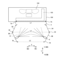
- FIG. 9 is a plan view showing the configurations of outdoor unit 100 and water sprinkler 1 according to Embodiment 5.
- FIG. 10 is a sectional view showing the configuration of an outdoor unit 100 and a water sprinkler 1 according to the fifth embodiment.
- the windbreak plate 3 has a first area on the outdoor unit side attached to the casing 101 of the outdoor unit 100 and a second area on the side opposite to the outdoor unit. are doing.
- the second region is a region on the opposite side of the outdoor unit, which is arranged with respect to the housing 101 of the outdoor unit 100 with the first region interposed therebetween.
- the second region is spaced apart from the casing 101 of the outdoor unit 100, and is located further from the casing 101 of the outdoor unit 100 than the first region.
- the other configurations are the same as those in any of the first to fourth embodiments, so the description thereof will be omitted here.
- windbreak plate 3A the windbreak plate 3 in the first area
- windbreak plate 3B the windbreak plate 3 in the second area
- Both the windbreak plate 3A and the windbreak plate 3B have a plate-like shape. More specifically, both the windbreak plate 3A and the windbreak plate 3B have a flat plate shape.
- the windbreak plate 3A and the windbreak plate 3B have the same size in the Z direction, and are connected by a connecting portion 30 extending in the Z direction, as shown in FIG. Note that the windbreak plate 3A and the windbreak plate 3B may be integrally molded, or may be formed separately and joined at the connecting portion 30.
- Embodiment 5 instead of using the windbreak plate 3 as a single flat plate, as shown in the plan view of FIG. It is divided into a windbreak plate 3B located at .
- the windbreak plate 3A includes a cut-and-raised portion 5.
- the windbreak plate 3A is inclined toward the outside in the X direction as it moves away from the casing 101 of the outdoor unit 100. Therefore, as shown in FIG. 9, the distance L3 in the X direction between the connecting parts 30 of the left and right windbreak plates 3 is smaller than the distance L1 in the X direction between the first ends 3a of the left and right windbreak plates 3A. big.
- the windbreak plate 3B is provided with a nozzle mounting hole 4 and a nozzle 6.
- the left and right windbreak plates 3B are arranged parallel to each other. Further, the left and right windbreak plates 3B are arranged to face each other. Therefore, as shown in FIG. 9, the distance L3 in the X direction between the connecting parts 30 of the left and right windbreak plates 3, and the distance L2 in the X direction between the second ends 3b of the left and right windbreak plates 3B. , are equal.
- FIG. 11 is a plan view showing the configuration of an outdoor unit 100 and a water sprinkler 1 according to a first modification of the fifth embodiment.
- cut-and-raised portions 5 are also provided on the left and right windbreak plates 3B.
- the cut-and-raised portions 5 provided on the left and right windbreak plates 3B are arranged downstream of the nozzle attachment hole 4 in the air flow direction shown by arrow A in FIG.
- the other configurations are the same as the fifth embodiment shown in FIG.
- cut-and-raised portions 5 are provided on both the windbreak plate 3A and the windbreak plate 3B. All of the airflow 13a (see FIG. 3) passing through the opening 5a of the cut and raised portion 5 is collected at the air intake port 102 of the outdoor unit 100. This increases the amount of air collected at the intake port 102, thereby improving energy saving performance.
- FIG. 12 is a plan view showing the configuration of an outdoor unit 100 and a water sprinkler 1 according to a second modification of the fifth embodiment.
- the left and right windbreak plates 3A are curved.
- the left and right windbreak plates 3A are curved so as to spread outward in the X direction as they move away from the casing 101 of the outdoor unit 100.
- the other configurations are the same as the fifth embodiment shown in FIG.
- the left and right windbreak plates 3A are curved.
- the degree of freedom in the cut-and-raised angle of the cut-and-raised portion 5 is improved, and the amount of airflow 13a passing through the opening 5a of the cut-and-raised portion 5 can be increased, so that energy saving performance is improved.
- air in the direction indicated by arrow A in FIG. 12 flows along the left and right windbreak plates 3A, the amount of air collected at the air intake port 102 increases, so that energy saving performance is improved.
- FIG. 13 is a plan view showing the configuration of an outdoor unit 100 and a water sprinkler 1 according to a third modification of the fifth embodiment.
- the left and right windbreak plates 3A are curved, similar to the second modification of the fifth embodiment.
- the left and right windbreak plates 3A are curved so as to spread outward in the X direction as they move away from the casing 101 of the outdoor unit 100.
- the left and right windbreak plates 3A and 3B are attached to correspond to the positions of both ends in the X direction of the ventilation chamber 124 of the housing 101.
- the other configurations are the same as the fifth embodiment shown in FIG.
- FIG. 14 is a plan view showing the configuration of an outdoor unit 100 and a water sprinkler 1 according to a fourth modification of the fifth embodiment.
- the left and right windbreak plates 3A are curved.
- the windbreak plate 3A and the windbreak plate 3B on the first end 103c side of the heat exchanger 103 are arranged inside the end of the first side surface 101b-1 of the housing 101.
- the windbreak plate 3A in the first region is curved or inclined so that it spreads outward in the X direction as it moves away from the housing 101. ing. Furthermore, the nozzle attachment hole 4 and the nozzle 6 are arranged on the windbreak plate 3B in the second area. In addition, in this configuration, the position of the nozzle 6 attached to the windshield plate 3B may be moved toward the heat exchanger 103 side, or may be moved toward the far side of the heat exchanger 103. As described above, in the fifth embodiment and the first to fourth variations thereof, the degree of freedom in the mounting position of the nozzle 6 is increased, water 12 can be sprayed over a wide area of the heat exchanger 103, and energy saving performance is improved. .
- the windbreak plate 3B in the second region may be inclined inward in the X direction as it moves away from the housing 101. That is, in the fourth modification shown in FIG. 14, the windbreak plate 3B in the second region is inclined toward the center of the outdoor unit 100.
- the nozzle 6 is attached to the windbreak plate 3B in the second area, which is made of a flat plate.
- the structure for mounting the nozzle 6 can be simplified by attaching it to the flat windbreak plate 3B, compared to the case of attaching it to the curved windbreak plate 3A.
- the sprinkler device 1 for the purpose of auxiliary cooling of an air conditioner and the function of auxiliary cooling of a similar air conditioner can be provided at a low cost.
- FIG. 15 is a perspective view showing the configuration of an outdoor unit 100 and a water sprinkler 1 according to the sixth embodiment.
- FIG. 16 is a rear view showing the configuration of the second cut-up portion 5A provided in the water sprinkler 1 according to the sixth embodiment.
- FIG. 16 shows the second cut-and-raised portion 5A viewed from the rear side in the Y direction.
- FIG. 17 is a side view showing the configuration of the second cut-and-raised portion 5A provided in the water sprinkler 1 according to the sixth embodiment.
- the water sprinkler 1 is provided with an upper plate 8 extending in the X direction.
- the upper plate 8 connects the upper ends 3c of the left and right windbreak plates 3 to each other. More specifically, the upper plate 8 connects at least a portion of the upper end portions 3c of the left and right windbreak plates 3 to each other.
- the upper plate 8 has a rectangular flat plate shape. The upper plate 8 and the upper ends 3c of the left and right windbreak plates 3 are fixed by, for example, welding or a jig.
- the upper plate 8 is formed with a second cut-and-raised portion 5A.
- the second cut-and-raised portion 5A extends in the X direction, as shown in FIG.
- the plate portion 5Ab of the second cut-and-raised portion 5A has a horizontally long rectangular flat plate shape extending in the X direction.
- the base end 5Ac of the second cut-and-raised portion 5A is disposed closer to the housing 101 than the plate portion 5Ab, and extends in the X direction.
- the opening 5Aa of the second cut-and-raised portion 5A faces toward the rear side in the Y direction.
- the second cut-and-raised portion 5A is formed in the same manner as the cut-and-raised portion 5 shown in the first embodiment.
- a rectangular notch is made with a cutter or the like at the location where the second cut-and-raised portion 5A is desired to be formed, leaving the base end portion 5Ac. That is, an angular U-shaped cut is made in the upper plate 8 so as to have the shape of the plate portion 5Ab. The cut passes through the thickness of the upper plate 8.
- a mold is set in the cut, and only the plate portion 5Ab is extruded by bending, starting from the base end 5c. As a result, a second cut-and-raised portion 5A is formed.
- the second cut-and-raised portion 5A may be arranged at the center of the upper plate 8 in the X direction, but is not limited to that case. As described in the fourth embodiment, when the machine room 121 and the ventilation chamber 124 are provided in the housing 101, the second cut-and-raised portion 5A is formed on both sides of the ventilation chamber 124 in the X direction. It is desirable to arrange it so that it corresponds to the position of .
- an upper plate is placed at a position connecting the upper ends 3c of the windbreak plates 3.
- a second cut-and-raised portion 5A is formed on the upper plate 8. According to this configuration, the wind flowing above the outdoor unit 100 can be collected from the second cut-and-raised portion 5A provided on the upper plate 8. Therefore, a larger amount of air can be collected to the heat exchanger 103 than the water sprinkler 1 described in Embodiments 1 to 5, and the energy saving effect of the outdoor unit 100 is further improved. be.
- the upper plate 8 can block sunlight onto the heat exchanger 103. Therefore, the temperature of the heat exchanger 103 can be kept lower than in a configuration in which the upper plate 8 is not provided. As a result, there is an advantage that the cooling capacity of the outdoor unit 100 is improved and the energy saving effect is further improved. Further, since the left and right windbreak plates 3 are attached to the housing 101 in a cantilevered manner, there is an advantage that the rigidity of the entire watering device 1 is improved by attaching the upper plate 8 to the left and right windbreak plates 3.
- FIG. 18 is a rear view showing the configuration of the third cut-and-raised portion 5B provided in the water sprinkler 1 according to the first modification of the sixth embodiment.
- FIG. 18 shows the third cut-and-raised portion 5B viewed from the rear side in the Y direction.
- FIG. 19 is a side view showing the configuration of the third cut-and-raised portion 5B provided in the water sprinkler 1 according to the first modification of the sixth embodiment.
- FIG. 20 is a perspective view showing the configuration of the third cut-and-raised portion 5B provided in the water sprinkler 1 according to the first modification of the sixth embodiment.
- two third cut-and-raised portions 5B are formed on the upper plate 8.
- the two third cut-and-raised portions 5B are arranged side by side in the X direction.
- the directions of the openings 5Ba of the two third cut and raised portions 5B are opposite. That is, the openings 5Ba of the two third cut-and-raised portions 5B face outward in the X direction of the upper plate 8.
- the opening 5Ba of the third cut-and-raised portion 5B located on the right side faces the right side
- the opening 5Ba of the third cut-and-raised portion 5B located on the left side faces the right side. facing left.
- the plate portion 5Bb of the third cut and raised portion 5B has a rectangular flat plate shape.
- the base end portion 5Bc of the third cut and raised portion 5B extends in the Y direction.
- the third cut-and-raised portion 5B of Modification 1 has a cut-and-raised shape that aims to collect the crosswind 13.
- Only one third cut-and-raised portion 5B may be provided as long as it fits within the upper plate 8, or a plurality of third cut-and-raised portions 5B may be provided by changing the dimensions.
- the third cut-and-raised portion 5B is formed by the same method as the second cut-and-raised portion 5A shown in the sixth embodiment. Therefore, the explanation thereof will be omitted here.
- FIG. 21 is a rear view showing the configuration of the third cut-and-raised portion 5B provided in the water sprinkler 1 according to the second modification of the sixth embodiment.
- FIG. 21 shows the third cut-and-raised portion 5B viewed from the rear side in the Y direction.
- FIG. 22 is a side view showing the configuration of the third cut-and-raised portion 5B provided in the water sprinkler 1 according to the second modification of the sixth embodiment.
- the directions of the openings 5Ba of the left and right third cut-and-raised portions 5B are opposite. That is, the openings 5Ba of the four third cut-and-raised portions 5B all face outward in the X direction of the upper plate 8. Specifically, as shown in FIG. 21, the openings 5Ba of the two third cut-and-raised portions 5B arranged on the right side both face the right side. On the other hand, the openings 5Ba of the two third cut-and-raised portions 5B arranged on the left side both face leftward.
- the plate portions 5Bb of the four third cut and raised portions 5B have a rectangular flat plate shape.
- the plate portions 5Bb of the four third cut-and-raised portions 5B may have the same shape and size, or may be different from each other. Further, the base end portions 5Bc of the four third cut and raised portions 5B each extend in the Y direction. Further, the cut-and-raise angles of the plate portions 5Bb of the four third cut-and-raise portions 5B may be the same or may be different from each other.
- FIG. 23 is a rear view showing the configuration of the second cut-and-raised portion 5A and the third cut-and-raised portion 5B provided in the water sprinkler 1 according to the third modification of the sixth embodiment.
- FIG. 23 shows the third cut-and-raised portion 5B viewed from the rear side in the Y direction.
- FIG. 24 is a side view showing the configuration of the second cut-and-raised portion 5A and the third cut-and-raised portion 5B provided in the water sprinkler 1 according to the third modification of the sixth embodiment.
- the second cut-and-raised portion 5A shown in the sixth embodiment and the left and right third cut-and-raised portions 5B shown in the first modification are provided. These three cut-and-raised portions are arranged side by side in the X direction, as shown in FIG. 23. In addition, in the X direction, the second cut-and-raised portion 5A is arranged between the left and right third cut-and-raised portions 5B.
- the second cut-and-raised portions 5A and the third cut-and-raised portions 5B may be provided as long as they fit in the upper plate 8, or a plurality of the second cut-and-raised portions 5B may be provided by changing the dimensions. You can do it like this.
- the number of pieces to be installed may be arbitrary.
- both the effects of the sixth embodiment and the effects of the first modification of the sixth embodiment can be obtained.
- This has the advantage that a larger amount of air can be collected into the heat exchanger 103, and the energy saving effect of the outdoor unit 100 is further improved.
- a windbreak plate 3 may be provided on at least one of the left and right sides of the first side surface portion 101b-1 of the casing 101.
- the windbreak plate 3 may be provided only on the right side of the first side surface portion 101b-1 of the casing 101 of the outdoor unit 100.
- 1 Water sprinkler device 3 Windbreak plate, 3A Windbreak plate, 3B Windbreak plate, 3a First end, 3b Second end, 3c Upper end, 4 Nozzle mounting hole, 5 Cut-and-raised part, 5A Cut-and-raised part, 5Aa opening, 5Ab plate part, 5Ac base end part, 5B cut and raised part, 5Ba opening, 5Bb plate part, 5Bc base end part, 5a opening, 5b plate part, 5c base end part, 6 nozzle, 6a tip part, 8 upper plate, 12 Water, 13 crosswind, 13a airflow, 13b airflow, 30 connection section, 40 water source, 41 water supply piping, 42 control panel, 43 solenoid valve, 44 control section, 100 outdoor unit, 101 housing, 101a top surface, 101b side surface, 101b-1 First side part, 101b-2 Second side part, 101b-3 Third side part, 102 Inlet, 103 Heat exchanger, 103a Refrigerant pipe, 103b Fin, 103c First end, 103d Second end
Landscapes
- Engineering & Computer Science (AREA)
- Chemical & Material Sciences (AREA)
- Combustion & Propulsion (AREA)
- Mechanical Engineering (AREA)
- General Engineering & Computer Science (AREA)
- Other Air-Conditioning Systems (AREA)
- Details Of Heat-Exchange And Heat-Transfer (AREA)
- Heat-Exchange Devices With Radiators And Conduit Assemblies (AREA)
Priority Applications (2)
| Application Number | Priority Date | Filing Date | Title |
|---|---|---|---|
| PCT/JP2022/017806 WO2023199471A1 (ja) | 2022-04-14 | 2022-04-14 | 散水装置 |
| JP2023535680A JP7412647B1 (ja) | 2022-04-14 | 2022-04-14 | 散水装置 |
Applications Claiming Priority (1)
| Application Number | Priority Date | Filing Date | Title |
|---|---|---|---|
| PCT/JP2022/017806 WO2023199471A1 (ja) | 2022-04-14 | 2022-04-14 | 散水装置 |
Publications (1)
| Publication Number | Publication Date |
|---|---|
| WO2023199471A1 true WO2023199471A1 (ja) | 2023-10-19 |
Family
ID=88329386
Family Applications (1)
| Application Number | Title | Priority Date | Filing Date |
|---|---|---|---|
| PCT/JP2022/017806 Ceased WO2023199471A1 (ja) | 2022-04-14 | 2022-04-14 | 散水装置 |
Country Status (2)
| Country | Link |
|---|---|
| JP (1) | JP7412647B1 (https=) |
| WO (1) | WO2023199471A1 (https=) |
Citations (4)
| Publication number | Priority date | Publication date | Assignee | Title |
|---|---|---|---|---|
| JPH05306823A (ja) * | 1992-04-30 | 1993-11-19 | Daikin Ind Ltd | 空気調和装置の室外機 |
| JP2003294269A (ja) * | 2002-04-01 | 2003-10-15 | Takasago Thermal Eng Co Ltd | 室外機の配置システム |
| WO2012063277A1 (ja) * | 2010-11-08 | 2012-05-18 | Nagahiro Tsuyoshi | 空調室外機冷却装置および熱交換システム |
| JP2013076527A (ja) * | 2011-09-30 | 2013-04-25 | Daikin Industries Ltd | 空気調和装置用の室外機 |
Family Cites Families (11)
| Publication number | Priority date | Publication date | Assignee | Title |
|---|---|---|---|---|
| JPS4717972Y1 (https=) * | 1969-09-05 | 1972-06-21 | ||
| JPH0373840U (https=) * | 1989-11-20 | 1991-07-25 | ||
| JP2009287880A (ja) * | 2008-05-30 | 2009-12-10 | Mitsubishi Electric Corp | 空調機用散水装置 |
| JP5606706B2 (ja) * | 2009-08-28 | 2014-10-15 | 三洋電機株式会社 | 室外機用冷却装置 |
| JP2011163731A (ja) * | 2010-02-15 | 2011-08-25 | Arimitsu Industry Co Ltd | 噴射装置 |
| JP2012047390A (ja) * | 2010-08-26 | 2012-03-08 | Aisaito:Kk | 室外機及びこれを備えた冷却システム |
| JP5829847B2 (ja) * | 2011-07-04 | 2015-12-09 | 株式会社いけうち | 室外機冷却装置 |
| JP2013076538A (ja) * | 2011-09-30 | 2013-04-25 | Daikin Industries Ltd | 空気調和装置の室外機 |
| JP6092766B2 (ja) * | 2013-12-26 | 2017-03-08 | ソフトバンク株式会社 | 空調システム |
| JP6430285B2 (ja) * | 2015-02-25 | 2018-11-28 | ダイセン・メンブレン・システムズ株式会社 | 熱交換器の冷却装置および冷却方法 |
| JP2018179418A (ja) * | 2017-04-14 | 2018-11-15 | 日立ジョンソンコントロールズ空調株式会社 | 室外ユニット、及び、当該室外ユニットを有する空気調和機 |
-
2022
- 2022-04-14 WO PCT/JP2022/017806 patent/WO2023199471A1/ja not_active Ceased
- 2022-04-14 JP JP2023535680A patent/JP7412647B1/ja active Active
Patent Citations (4)
| Publication number | Priority date | Publication date | Assignee | Title |
|---|---|---|---|---|
| JPH05306823A (ja) * | 1992-04-30 | 1993-11-19 | Daikin Ind Ltd | 空気調和装置の室外機 |
| JP2003294269A (ja) * | 2002-04-01 | 2003-10-15 | Takasago Thermal Eng Co Ltd | 室外機の配置システム |
| WO2012063277A1 (ja) * | 2010-11-08 | 2012-05-18 | Nagahiro Tsuyoshi | 空調室外機冷却装置および熱交換システム |
| JP2013076527A (ja) * | 2011-09-30 | 2013-04-25 | Daikin Industries Ltd | 空気調和装置用の室外機 |
Also Published As
| Publication number | Publication date |
|---|---|
| JP7412647B1 (ja) | 2024-01-12 |
| JPWO2023199471A1 (https=) | 2023-10-19 |
Similar Documents
| Publication | Publication Date | Title |
|---|---|---|
| EP3745075B1 (en) | Indoor heat exchanger and air conditioning device | |
| CN110762908B (zh) | 一种蒸发式冷凝器及其空气调节系统 | |
| CN107843030B (zh) | 室内换热器、空调室内机及空调器 | |
| CN220287611U (zh) | 空调器室外机及空调器 | |
| JP7412647B1 (ja) | 散水装置 | |
| JP5396580B2 (ja) | 冷温水コイルを内蔵した空気熱交換器 | |
| JP2009287880A (ja) | 空調機用散水装置 | |
| KR101913720B1 (ko) | 하이브리드 공기조화 시스템 | |
| JP2022172631A (ja) | 空気調和システム、および架台 | |
| JP2013076521A (ja) | 空気調和装置の室外機 | |
| CN219624176U (zh) | 空调室外机 | |
| KR200254476Y1 (ko) | 공기조화기용 엘리미네이터 | |
| CN107843139B (zh) | 翅片组件、换热器及空调器室内机 | |
| JP2007139329A (ja) | 冷風発生装置 | |
| JP5177254B2 (ja) | 冷却システム | |
| WO2020121517A1 (ja) | 室内機および空気調和機 | |
| DE112019007369B4 (de) | Inneneinheit einer Klimaanlage | |
| JP5803974B2 (ja) | 化粧パネル及びそれを備えた空気調和機の室内ユニット | |
| KR200245714Y1 (ko) | 패키지에어콘의실내기 | |
| JP2015169358A (ja) | 熱交換器 | |
| CN223360770U (zh) | 空调室外机 | |
| CN107878147B (zh) | 车辆的空调系统及车辆 | |
| JPS6326293B2 (https=) | ||
| CN222257799U (zh) | 一种伪装型冷却装置 | |
| CN222012136U (zh) | 空调室外机 |
Legal Events
| Date | Code | Title | Description |
|---|---|---|---|
| WWE | Wipo information: entry into national phase |
Ref document number: 2023535680 Country of ref document: JP |
|
| 121 | Ep: the epo has been informed by wipo that ep was designated in this application |
Ref document number: 22937450 Country of ref document: EP Kind code of ref document: A1 |
|
| NENP | Non-entry into the national phase |
Ref country code: DE |
|
| 122 | Ep: pct application non-entry in european phase |
Ref document number: 22937450 Country of ref document: EP Kind code of ref document: A1 |