WO2023199409A1 - レーザ加工装置、制御装置、レーザ加工システム、およびレーザ加工方法 - Google Patents
レーザ加工装置、制御装置、レーザ加工システム、およびレーザ加工方法 Download PDFInfo
- Publication number
- WO2023199409A1 WO2023199409A1 PCT/JP2022/017619 JP2022017619W WO2023199409A1 WO 2023199409 A1 WO2023199409 A1 WO 2023199409A1 JP 2022017619 W JP2022017619 W JP 2022017619W WO 2023199409 A1 WO2023199409 A1 WO 2023199409A1
- Authority
- WO
- WIPO (PCT)
- Prior art keywords
- processing
- temperature
- amount
- laser
- optical component
- Prior art date
- Legal status (The legal status is an assumption and is not a legal conclusion. Google has not performed a legal analysis and makes no representation as to the accuracy of the status listed.)
- Ceased
Links
Images






Classifications
-
- B—PERFORMING OPERATIONS; TRANSPORTING
- B23—MACHINE TOOLS; METAL-WORKING NOT OTHERWISE PROVIDED FOR
- B23K—SOLDERING OR UNSOLDERING; WELDING; CLADDING OR PLATING BY SOLDERING OR WELDING; CUTTING BY APPLYING HEAT LOCALLY, e.g. FLAME CUTTING; WORKING BY LASER BEAM
- B23K26/00—Working by laser beam, e.g. welding, cutting or boring
- B23K26/02—Positioning or observing the workpiece, e.g. with respect to the point of impact; Aligning, aiming or focusing the laser beam
- B23K26/04—Automatically aligning, aiming or focusing the laser beam, e.g. using the back-scattered light
- B23K26/046—Automatically focusing the laser beam
-
- B—PERFORMING OPERATIONS; TRANSPORTING
- B23—MACHINE TOOLS; METAL-WORKING NOT OTHERWISE PROVIDED FOR
- B23K—SOLDERING OR UNSOLDERING; WELDING; CLADDING OR PLATING BY SOLDERING OR WELDING; CUTTING BY APPLYING HEAT LOCALLY, e.g. FLAME CUTTING; WORKING BY LASER BEAM
- B23K26/00—Working by laser beam, e.g. welding, cutting or boring
- B23K26/02—Positioning or observing the workpiece, e.g. with respect to the point of impact; Aligning, aiming or focusing the laser beam
- B23K26/06—Shaping the laser beam, e.g. by masks or multi-focusing
- B23K26/064—Shaping the laser beam, e.g. by masks or multi-focusing by means of optical elements, e.g. lenses, mirrors or prisms
- B23K26/0648—Shaping the laser beam, e.g. by masks or multi-focusing by means of optical elements, e.g. lenses, mirrors or prisms comprising lenses
-
- B—PERFORMING OPERATIONS; TRANSPORTING
- B23—MACHINE TOOLS; METAL-WORKING NOT OTHERWISE PROVIDED FOR
- B23K—SOLDERING OR UNSOLDERING; WELDING; CLADDING OR PLATING BY SOLDERING OR WELDING; CUTTING BY APPLYING HEAT LOCALLY, e.g. FLAME CUTTING; WORKING BY LASER BEAM
- B23K26/00—Working by laser beam, e.g. welding, cutting or boring
- B23K26/36—Removing material
-
- B—PERFORMING OPERATIONS; TRANSPORTING
- B23—MACHINE TOOLS; METAL-WORKING NOT OTHERWISE PROVIDED FOR
- B23K—SOLDERING OR UNSOLDERING; WELDING; CLADDING OR PLATING BY SOLDERING OR WELDING; CUTTING BY APPLYING HEAT LOCALLY, e.g. FLAME CUTTING; WORKING BY LASER BEAM
- B23K26/00—Working by laser beam, e.g. welding, cutting or boring
- B23K26/70—Auxiliary operations or equipment
- B23K26/702—Auxiliary equipment
- B23K26/707—Auxiliary equipment for monitoring laser beam transmission optics
Definitions
- the present disclosure relates to a laser processing device, a control device, a laser processing system, and a laser processing method that perform laser processing.
- a laser processing device that performs laser processing on a workpiece by irradiating the workpiece with laser light focuses the laser light on a specific position using an optical component included in the processing head.
- the workpiece is irradiated.
- a thermal lens effect occurs in which the refractive index of the optical component changes when the optical component absorbs laser light. For this reason, in the laser processing apparatus, the imaging performance of the laser beam changes, and although the processing was good at the start of processing, processing defects may occur as the processing progresses.
- the laser processing device described in Patent Document 1 adjusts the focal position of the laser beam by having a drive motor move the lens in the optical axis direction according to the lens temperature detected by a temperature sensor provided on the lens. ing.
- the present disclosure has been made in view of the above, and aims to provide a laser processing apparatus that can sufficiently suppress deterioration of laser processing quality.
- a laser processing device of the present disclosure includes a beam characteristic calculation unit that calculates beam characteristics of a laser beam irradiated to an optical component arranged in a processing head, and a processing head.
- the optical device includes a temperature estimating unit that estimates the estimated temperature of the optical component based on temperature information that is information on the temperature measured by a temperature sensor disposed inside the optical component and beam characteristics.
- the laser processing apparatus of the present disclosure also includes a thermal lens estimating section that estimates the amount of thermal lens of the optical component based on the estimated temperature, and a processing unit that processes the imaging performance of the imaging optical system of the processing head based on the amount of thermal lens.
- the laser processing device of the present disclosure also includes a correction amount calculation unit that calculates a correction amount of processing parameters based on the estimated amount of change in imaging performance, and a correction amount calculation unit that controls laser processing using a laser beam, and also controls laser processing using a laser beam. and a control unit that changes the machining parameters based on the correction amount.
- the laser processing apparatus has the effect of sufficiently suppressing deterioration of laser processing quality.
- a diagram showing the configuration of a laser processing device according to Embodiment 1. A diagram for explaining the arrangement of optical components included in the processing head of the laser processing device according to the first embodiment.
- a diagram for explaining the thermal lens effect that occurs in the laser processing device according to the first embodiment Block diagram showing the functional configuration of the laser processing device according to the first embodiment
- Flowchart showing processing procedure of processing control by the processing control unit of the laser processing apparatus according to the first embodiment Block diagram showing the functional configuration of the laser processing device according to the second embodiment
- Block diagram showing the functional configuration of a laser processing device according to Embodiment 4 A diagram showing a configuration example of a neural network model according to Embodiment 4
- FIG. 1 is a diagram showing the configuration of a laser processing apparatus according to a first embodiment.
- two axes in a plane parallel to the upper surface of the work W which is a plate-shaped workpiece, and mutually orthogonal, will be referred to as an X axis and a Y axis.
- the axis perpendicular to the X-axis and the Y-axis is defined as the Z-axis.
- the XY plane is a horizontal plane
- the Z-axis direction is a direction parallel to the vertical direction.
- the workpiece W is not limited to a plate shape.
- the laser processing device 100 is a device that performs laser processing on the workpiece W by irradiating the workpiece W with a laser beam L, which is a laser beam.
- the laser processing apparatus 100 processes the workpiece W by focusing laser light L using optical components included in the processing head 3 and irradiating the workpiece W with the focused laser light L.
- the laser processing apparatus 100 includes a laser oscillator 1, a control section 11, an optical fiber 2, and a processing head 3.
- the processing head 3 includes a collimating lens 4, an imaging optical system 5, two optical component holders 6, two temperature sensors 7, a protective glass 8, a processing nozzle 9, and a drive unit 10A that is a motor drive device. ⁇ 10C.
- the control unit 11 is connected to the laser oscillator 1 and the processing head 3, and controls the laser oscillator 1 and the processing head 3.
- the control section 11 is arranged in a processing control section 102 (not shown in FIG. 1), which will be described later.
- a laser oscillator 1 oscillates a laser beam L.
- the optical fiber 2 transmits the laser beam L generated by the laser oscillator 1 and sends it into the processing head 3 .
- the optical component holder 6 disposed on the upper side supports the collimating lens 4, and the optical component holder 6 disposed on the lower side supports the imaging optical system 5.
- a temperature sensor 7 is arranged in each optical component holder 6.
- the collimating lens 4 converts the laser beam L into parallel light and sends it to the imaging optical system 5.
- the imaging optical system 5 focuses the laser beam L on a specific position.
- the laser beam L that has passed through the imaging optical system 5 is sent to the processing nozzle 9 via the protective glass 8.
- the protective glass 8 protects components placed within the processing head 3 from splashes during laser processing.
- the processing nozzle 9 irradiates the irradiation position on the workpiece W with the laser light L that has passed through the protective glass 8. Processing gas is supplied to the inside of the processing head 3 .
- the processing head 3 injects processing gas to the workpiece W when irradiating the workpiece W with the laser beam L.
- the processing nozzle 9 has an opening on the optical path of the laser beam L between the imaging optical system 5 and the work W, and the laser beam L and the processing gas pass through this opening.
- a Z-axis motor (not shown) that moves the processing head 3 in the Z-axis direction and a drive unit 10A that drives the Z-axis motor are arranged in the laser processing apparatus 100.
- the Z-axis motor is connected to a shaft on which the processing head 3 is installed (an axis extending in the Z-axis direction), and moves the processing head 3 along the Z-axis in a direction parallel to the Z-axis direction.
- the laser processing apparatus 100 also includes an X-axis motor (not shown) and a Y-axis motor (not shown) that move a processing table (not shown) on which the workpiece W is placed within the A drive section (not shown) that drives the axis motor and a drive section (not shown) that drives the Y-axis motor are arranged.
- the X-axis motor is connected to a shaft extending in the X-axis direction
- the Y-axis motor is connected to a shaft extending in the Y-axis direction.
- the X-axis motor and the Y-axis motor move the processing table in the XY plane along the X and Y axes.
- the control unit 11 executes processing by controlling the laser oscillator 1, processing head 3, drive units 10A to 10C, etc., based on processing parameters that are numerical parameters related to laser processing.
- the control section 11 controls the drive sections 10A to 10C, and the drive sections 10A to 10C drive motors under the control of the control section 11.
- the drive unit 10A operates in accordance with the operation of the motor, and changes the relative position between the processing head 3 and the workpiece W.
- FIG. 1 illustrates a case where the drive unit 10A moves the processing head 3 to change the relative position between the processing head 3 and the workpiece W.
- the drive units 10B and 10C change the positional relationship between the imaging position of the imaging optical system 5 of the laser beam L and the workpiece W.
- the drive unit 10B is a drive unit for the collimating lens 4, and changes the diameter of the image formed by the imaging optical system 5 by changing the position of the collimating lens 4.
- the drive unit 10C is a drive unit for the imaging optical system 5, and changes the position of imaging by the imaging optical system 5 by changing the position of the imaging optical system 5.
- the type of laser oscillator 1 is not limited.
- An example of the laser oscillator 1 is a fiber laser oscillator that transmits laser light L through an optical fiber 2.
- the laser oscillator 1 may be a direct diode laser, a carbon dioxide laser, a copper vapor laser, various ion lasers, a solid state laser using YAG (Yttrium Aluminum Garnet) crystal, etc. as an excitation medium.
- the laser processing apparatus 100 may include a wavelength conversion section that converts the wavelength of the laser beam L oscillated by the laser oscillator 1.
- the number of collimating lenses 4 may be one or multiple.
- the number of the imaging optical system 5 may be one or more.
- the optical system disposed in the processing head 3 may be a zoom optical system that changes the imaging diameter of the imaging point by displacing the position of the optical system.
- the optical system disposed in the processing head 3 may be an optical system in which the driving section displaces the collimating lens 4 to adjust the divergence angle of incidence on the imaging optical system 5, thereby displacing the imaging position. good.
- the imaging position changed by the drive unit 10C may be at the beam waist position of the optical system, or may be at a position shifted from the beam waist position.
- the laser processing apparatus 100 changes the position of the imaging point of the laser beam L and the height direction of the work W without changing the relationship between the height direction position of the processing nozzle 9 and the height direction position of the workpiece W.
- the relationship with the position may also be changed.
- the control unit 11 controls the drive unit 10C, so that the drive unit 10C changes the position of the imaging optical system 5 in the height direction.
- drive units other than the drive units 10B and 10C may drive optical components other than the imaging optical system 5.
- the number of optical components driven by the processing head 3 may be one or more types.
- the optical components in the first embodiment are the collimating lens 4, the imaging optical system 5, and the protective glass 8, but optical components such as a mirror may be arranged inside the processing head 3.
- the laser beam L emitted from the optical fiber 2 passes through the collimating lens 4, is imaged by the imaging optical system 5, and passes through the protective glass 8 to be directed to the workpiece W, which is the object to be processed. irradiated. Thereby, the workpiece W is processed by the laser beam L.
- FIG. 2 is a diagram for explaining the arrangement of optical components included in the processing head of the laser processing apparatus according to the first embodiment.
- the arrangement of the collimating lens 4 will be described, but the arrangement of the imaging optical system 5 is also the same as that of the collimating lens 4.
- optical components such as the collimating lens 4 are held by an optical component holder 6, such as a lens holder, which is an example of a gripping section.
- the gripping section is composed of a member that grips an optical component, such as an optical component holder 6 that grips a lens such as the collimating lens 4, or a mirror holder (not shown) that grips a mirror (not shown).
- a temperature sensor 7 is arranged in the optical component holder 6.
- the temperature sensor 7 are a thermocouple and a thermistor.
- the optical component holder 6 may have a water channel 12 for cooling the optical component holder 6, as shown in FIG. When the optical component holder 6 has the water channel 12, the optical component is cooled by flowing cooling water into the water channel 12. Note that the optical component holder 6 that holds the imaging optical system 5 may also be provided with the water channel 12.
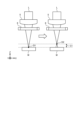
- FIG. 3 is a diagram for explaining the thermal lens effect that occurs in the laser processing apparatus according to the first embodiment.
- the left side shows the imaging point position D1 at the start of processing
- the right side shows the imaging point position D2 after the start of processing.
- the glass material or coating of the optical component absorbs the laser beam L emitted by the laser oscillator 1 in a transmission optical system such as a lens or a reflection optical system such as a mirror.
- a transmission optical system such as a lens or a reflection optical system such as a mirror.
- the refractive index (refractive index distribution) of the optical component changes, and a thermal lens effect occurs.
- the time period during which a temperature distribution is formed in the optical component varies depending on the material of the optical component and the diameter of the irradiated beam.
- the imaging position of the laser beam L at the imaging point may change between when processing starts and after processing starts. For example, as shown on the left side of FIG. 3, when the laser processing apparatus 100 starts processing, the imaging point is located on the surface of the workpiece W, and good processing is performed. However, as the laser processing device 100 progresses, the imaging position changes as shown on the right side of FIG. 3, and the imaging point moves from the surface of the workpiece W toward the processing head 3. Defects may occur.
- condition for good machining is not limited to the case where the imaging point is on the workpiece W. In some cases, better machining can be achieved when the imaging point is located on the processing head 3 side than on the workpiece W, and in other cases, better machining can be achieved when the imaging point is located on the depth direction side of the workpiece W.
- the thermal lens effect not only causes a change in the imaging position, but also causes changes in imaging magnification, beam waist position, aberrations, etc., which may deteriorate the imaging performance of the entire processing optical system. be.
- the laser processing apparatus 100 of the first embodiment takes into account the temperature sensor 7 included in the processing head 3 and accurately estimates the temperature of the optical component even in a case where a thermal lens effect occurs.
- the laser processing apparatus 100 then accurately estimates the amount of change in imaging performance from before the start of processing (hereinafter referred to as the amount of change in imaging performance) based on the estimated temperature of the optical component, and calculates the amount of change in imaging performance.
- the processing parameter is corrected by determining the correction amount of the processing parameter according to the above.
- Examples of processing parameters include the imaging magnification, the height of the processing nozzle 9 from the workpiece W (distance between the processing nozzle 9 and the workpiece W), the imaging position of the imaging optical system 5, and the workpiece W in the Z-axis direction. , positional relationship between optical components, processing speed, laser output value, pulse frequency of laser beam L, pulse duty ratio of laser beam L, nozzle diameter, type of laser beam mode, center of nozzle hole and the positional relationship of the laser beam.
- the processing parameters there are parameters that have a certain processing margin, such as cutting speed, imaging position, and laser output.
- the machining margin refers to the range (change range of machining parameters) in which the same machining quality can be achieved even if the machining parameters are changed.
- the laser processing apparatus 100 of the first embodiment corrects the processing parameters by taking into account changes in the imaging performance of the imaging optical system 5, it is possible to sufficiently suppress deterioration in laser processing quality. Furthermore, in the laser processing apparatus 100, the temperature sensor 7 is attached to a gripping section (optical component holder 6) that grips an optical component. Thereby, the laser processing apparatus 100 can estimate the influence of the heat transfer on the optical component by the purge gas contained in the processing head 3 and the cooling effect by the optical component holder 6. Therefore, the laser processing apparatus 100 can estimate state changes such as temperature changes of the processing head 3, and can estimate the amount of change in imaging performance in detail in real time.
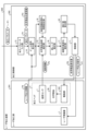
- FIG. 4 is a block diagram showing the functional configuration of the laser processing apparatus according to the first embodiment.
- the laser processing apparatus 100 includes a laser processing section 101 and a processing control section 102 that is a control device. Note that the laser processing section 101 and the processing control section 102 may be connected via a network or the like.
- the laser processing section 101 includes a laser oscillator 1, an optical fiber 2 (not shown in FIG. 4), and a processing head 3.
- the processing head 3 includes a temperature sensor 7, an optical component 30, and a drive section 10X.
- the optical components 30 include a collimating lens 4, an imaging optical system 5, and the like.
- the drive unit 10X includes drive units 10B, 10C, and the like.
- illustration of the optical component holder 6, the protective glass 8, the processing nozzle 9, and the drive unit 10A is omitted.
- the processing control section 102 includes a processing parameter input section 13 , a beam characteristic calculation section 14 , an optical component temperature estimation section 15 , a thermal lens estimation section 16 , an imaging performance change estimation section 17 , and a correction amount calculation section 22 . , and a control section 11.
- the processing parameter input unit 13 receives a processing parameter P1 input from outside the laser processing apparatus 100 and outputs it to the beam characteristic calculation unit 14. Note that the machining parameter P1 received by the machining parameter input section 13 and the machining parameter P1 corrected by the control section 11 may be different machining parameters.
- the beam characteristic calculation unit 14 receives the processing parameter P1 sent from the processing parameter input unit 13.
- the beam characteristic calculation unit 14 also receives laser output information P4 sent from an output monitor mounted on the laser oscillator 1.
- the laser output information P4 is information indicating the output value of the laser beam L.
- the beam characteristic calculation unit 14 may extract the laser output information P4 from the processing parameters P1 output from the processing parameter input unit 13. Further, the beam characteristic calculation section 14 may calculate the laser output information P4 from the laser output command P7 actually outputted from the control section 11 to the laser oscillator 1.
- the beam characteristic calculation unit 14 extracts optical component position information P3 indicating the position of the optical component 30 from the processing parameters P1 received from the processing parameter input unit 13.
- the beam characteristic calculation unit 14 performs ray tracing using the laser output information P4 and the optical component position information P3 to calculate the beam diameter, incident angle, and optical component 30 of the laser beam L irradiated onto each optical component 30.
- One or more beam characteristics of the exit angle and the beam intensity are calculated.
- the beam characteristic calculation unit 14 outputs the calculated beam characteristics to the optical component temperature estimation unit 15.
- the beam characteristic calculation unit 14 also outputs the optical component position information P3 (lens position, etc.) and the calculated beam diameter to the thermal lens estimation unit 16.
- the beam characteristic calculation unit 14 may calculate the optical component position information P3 from the position command that the drive unit 10X actually outputs to the optical component 30 or the optical component holder 6.
- the beam characteristic calculation unit 14 may calculate the optical component position information P3 from the drive command (command for moving the optical component 30) that the control unit 11 actually outputs to the drive unit 10X.
- the beam characteristic calculation unit 14 also calculates optical component position information P3 based on the imaging magnification, the height of the processing nozzle 9 from the workpiece W, the positional relationship between the imaging position and the workpiece W, etc. included in the processing parameter P1. may be calculated.
- the optical component temperature estimation section 15 receives the beam characteristics of each optical component 30 from the beam characteristic calculation section 14, and also receives temperature information P5 from the temperature sensor 7 disposed within the processing head 3. Temperature information P5 is information on the temperature of optical component 30.
- the optical component temperature estimation unit 15 estimates the temperature distribution (estimated temperature) of the optical component 30 based on the received temperature information P5 and beam characteristics. Specifically, the optical component temperature estimation unit 15 calculates the heating effect caused by the optical component 30 absorbing the laser beam L, the cooling effect by the water channel 12 of the optical component holder 6, and the cooling effect of the atmosphere inside the processing head 3.
- the temperature distribution of the optical component 30 is estimated by considering the following.
- the optical component temperature estimation unit 15 may estimate the temperature of at least one point on the surface or inside of the optical component 30 for each of the optical components 30.
- the optical component temperature estimation section 15 outputs the calculated temperature distribution of the optical component 30 to the thermal lens estimation section 16. The method for calculating the temperature distribution will be described later.
- the thermal lens estimation section 16 estimates the amount of thermal lens of each optical component 30 based on the information received from the optical component temperature estimation section 15 and the information received from the beam characteristic calculation section 14. Specifically, the thermal lens estimation unit 16 estimates the amount of thermal lens of each optical component 30 based on the temperature distribution of the optical component 30, the optical component position information P3, and the beam diameter. The thermal lens estimation unit 16 calculates the amount of thermal lens as a virtual lens having a focal length. The thermal lens estimation section 16 outputs the calculated amount of thermal lens to the imaging performance change estimation section 17.
- the imaging performance change estimation unit 17 receives the amount of thermal lens of each optical component 30 from the thermal lens estimation unit 16.
- the imaging performance change estimating unit 17 estimates the imaging performance change amount (estimated imaging performance change amount) on the workpiece W based on the amount of thermal lens of each optical component 30.
- the imaging performance change estimating unit 17 estimates the imaging performance change amount on the workpiece W by estimating the imaging performance change amount in consideration of the processing optical system of the processing head 3.
- the amount of change in imaging performance is the amount of change in imaging performance between before and after the start of processing.
- the imaging performance change amount here is based on the imaging performance at the start of processing.
- the start of processing may be the start of the processing program, or the timing at which the laser output in the laser output information P4 reaches a specific value after a specific time has elapsed since the laser output value in the laser output information P4 became 0 [W]. It may be.
- the imaging performance change estimation unit 17 outputs the estimated imaging performance change amount to the correction amount calculation unit 22.
- the correction amount calculation unit 22 calculates the correction amount for returning the imaging performance to the state before the start of processing, based on the received imaging performance change amount.
- the correction amount is, for example, a position correction amount for correcting the position of the optical component 30.
- the correction amount is a correction amount for correcting imaging performance.
- the correction amount calculation unit 22 outputs the calculated correction amount to the control unit 11.
- the control unit 11 controls at least one of the laser oscillator 1 and the processing head 3 based on the correction amount so that the evaluation value of the imaging performance becomes constant.
- the control unit 11 outputs a laser output command P7 to the laser oscillator 1.
- the control section 11 outputs the optical component displacement amount P6 to the drive section 10X. Note that the control unit 11 may adjust the position of the processing head 3 based on the correction amount so that the evaluation value of the imaging performance becomes constant.
- the control unit 11 uses, for example, a position command to the optical component 30 specified in the processing program and a correction amount of the position command for the optical component 30 to determine the amount of optical component displacement for controlling the position of the optical component 30.
- the optical component displacement amount P6 includes a command for controlling the position of the collimating lens 4, a command for controlling the position of the imaging optical system 5, and the like.
- control unit 11 controls the laser output of the laser oscillator 1 using, for example, an output command of the laser beam L to the laser oscillator 1 specified in the processing program and a correction amount of the output command of the laser beam L.
- a laser output command P7 is output for the purpose.
- the laser output command P7 includes the laser output value, the pulse frequency of the laser beam L, the duty ratio of the pulse of the laser beam L, the type of laser beam mode, and the like.
- the evaluation value of the imaging performance becomes higher as the amount of change in the position of the imaging point from the start of processing is smaller. That is, the evaluation value of the imaging performance is the amount of change in the position of the imaging point with reference to the time at the start of processing. Therefore, by the control unit 11 adjusting the position of the optical component 30 so that the evaluation value of the imaging performance becomes constant, the imaging performance at the start of processing is maintained.
- control unit 11 may maintain good machining by adjusting machining parameters other than the machining parameter P1 adjusted to correct the imaging performance. Further, the control unit 11 is not limited to adjusting the processing parameter P1 so that the evaluation value of the imaging performance is constant, but may adjust the processing parameter P1 so that the evaluation value falls within a specific range. For example, in the case of an imaging position, the specific range is a margin of variation in the imaging position.
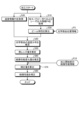
- FIG. 5 is a flowchart showing processing procedures for processing control by the processing control unit of the laser processing apparatus according to the first embodiment.
- the beam characteristic calculation unit 14 acquires processing parameters P1 and laser output information P4 (step S10). Specifically, the beam characteristic calculation section 14 acquires the processing parameter P1 from the processing parameter input section 13, and obtains the laser output information P4 from the output monitor installed in the laser oscillator 1.
- the beam characteristic calculation unit 14 extracts optical component position information P3 indicating the position of the optical component 30 from the processing parameters P1 acquired from the processing parameter input unit 13.
- the beam characteristic calculation unit 14 calculates the beam characteristics of the laser light L irradiated to each optical component 30 by performing ray tracing using the laser output information P4 and the optical component position information P3 (step S20).
- the beam characteristic calculation section 14 sends the calculated beam characteristics to the optical component temperature estimation section 15.
- the optical component temperature estimation section 15 acquires the beam characteristics of each optical component 30 from the beam characteristic calculation section 14, and also acquires temperature information P5 from the temperature sensor 7 arranged in the processing head 3 (step S30). Note that the process by which the optical component temperature estimator 15 acquires the temperature information P5 may be executed before the process in step S20, or may be executed before the process in step S10.
- the optical component temperature estimation unit 15 estimates the temperature distribution of the optical component 30 based on the acquired temperature information P5 and beam characteristics (step S40).
- the optical component temperature estimation section 15 sends the calculated temperature distribution to the thermal lens estimation section 16.
- the thermal lens estimation section 16 estimates the amount of thermal lens of each optical component 30 based on the temperature distribution received from the optical component temperature estimation section 15 (step S50).
- the thermal lens estimation section 16 sends the estimated amount of thermal lens of each optical component 30 to the imaging performance change estimation section 17 .
- the imaging performance change estimating unit 17 estimates the amount of imaging performance change in the workpiece W based on the thermal lens amount of each optical component 30 received from the thermal lens estimating unit 16 (step S60).
- the imaging performance change estimation unit 17 sends the estimated imaging performance change amount to the correction amount calculation unit 22.
- the correction amount calculation unit 22 calculates the correction amount for correcting the imaging performance based on the imaging performance change amount received from the imaging performance change estimation unit 17 (step S70).
- the correction amount calculation unit 22 outputs the correction amount to the control unit 11.
- the control unit 11 corrects the imaging performance by outputting a position command corresponding to the correction amount to the laser processing unit 101 (step S80). Note that the control unit 11 may output a position command corresponding to the correction amount to the drive unit 10X or the drive unit 10A.
- a laser processing device as a comparative example will be explained.
- a temperature sensor provided on a lens in a processing head detects the lens temperature, and adjusts the focal position based on the lens temperature.
- the influence of the laser output cannot be taken into account, so the amount of change in the imaging position during laser processing cannot be reflected in the control of light focusing. For this reason, deterioration in the processing quality of laser processing due to changes in the imaging performance of the imaging optical system is not suppressed, making it impossible to maintain the processing quality.
- the processing control unit 102 estimates the change in the imaging performance of the imaging optical system 5 based on the laser output information P4, the optical component position information P3, and the temperature information P5, and Since the position is corrected, it is possible to accurately adjust the imaging position.
- the absorption rate of the laser beam L in one optical component 30 is ⁇
- the mass of the optical component 30 is m [kg]
- the specific heat is c [J/kg ⁇ K]
- the laser output irradiated to the optical component 30 is P
- ⁇ is a time constant
- (i) is a calculation step of the step time
- the temperature rise dT(i) of the optical component 30 irradiated with the laser beam L of the step time dt can be approximated by the following equation (1). I can do it.
- the optical component temperature estimation section 15 changes the time constant ⁇ according to the beam diameter calculated by the beam characteristic calculation section 14. Further, the optical component temperature estimation unit 15 may change the time constant ⁇ according to the processing parameter P1 such as the imaging magnification.
- the optical component temperature estimation unit 15 calculates the temperature rise dT(i) of the optical component 30 at the position of the optical component 30. It may be estimated using a polynomial, or may be estimated using a value that approximates the beam intensity distribution of the laser light L. Furthermore, if it is difficult to approximate the beam intensity distribution, the beam intensity distribution may be manually set as a fixed value.
- the temperature increase component due to beam absorption at the beam center at the i time step is assumed to be dTp center (i), and the temperature increase component at the beam end is assumed to be dTp edge (i).
- the temperature of the optical component holder 6 output by the temperature sensor 7 is defined as temperature T H.
- T H The temperature of the optical component holder 6 output by the temperature sensor 7
- heat transfer occurs between the optical component holder 6 and the beam end position of the laser beam L of the optical component 30. Therefore, if the temperature at the beam end is T edge , the temperature-related parameters such as thermal resistance are k w , and the time constant is ⁇ W , then the temperature at the beam end is T edge , and the cooling from the optical component holder 6 is The relationship between the temperature change component dT c (i) and the temperature change component dT c (i) can be approximated as shown in the following equation (2).
- the temperature change component of the purge gas corresponding to the cooling effect of the purge gas inside the processing head 3 (the effect of cooling from the gas purging the inside of the processing head 3) is as follows: where the temperature of the purge gas is T g and the temperature at the beam center is T If center is assumed, approximation can be made as shown in the following equations (3) and (4) using a parameter kg related to the temperature at the beam center and a parameter kg edge related to the temperature at the end of the beam.
- dT cgcenter (i) in equation (3) is a temperature change component at the beam center
- dT cgedge (i) in equation (4) is a temperature change component at the beam end.
- T g may be the value of the temperature sensor 7 of the optical component holder 6 before processing, or it may be a value directly measured by a temperature sensor (not shown) placed near the optical path in the processing head 3. It's okay. Further, T g may be a value calculated based on the value measured by the temperature sensor 7 during laser processing and the structure inside the processing head 3. Since the purge gas directly cools the optical component 30, the optical component temperature estimation unit 15 may approximate the temperature change component of the purge gas without providing a time constant ⁇ .
- the temperature T center (i) at the center of the beam can be expressed as the following equation (5).
- the temperature T edge (i) at the beam end can be expressed as the following equation (6).
- ⁇ T(i) which is the difference between T center (i) and T edge (i) here, can be expressed by the following equation (7).
- the optical component temperature estimation unit 15 may use ⁇ T(i) expressed by this equation (7) as the temperature distribution. Further, the temperature distribution of the optical component 30 is not limited to the beam center and the beam end, but temperature estimation points between the beam center and the beam end may be added. The optical component temperature estimation unit 15 can estimate a more detailed temperature distribution as the number of temperature estimation points increases.
- the optical component temperature estimating unit 15 may estimate the temperature distribution by additionally considering other cooling components.
- the optical component temperature estimating unit 15 may estimate the temperature distribution by taking into consideration, for example, heat exchange between the beam center and the beam end, that is, the influence of thermal radiation from the processing head 3.
- the optical component temperature estimating unit 15 calculates only the temperature difference at this one point in the temperature distribution (change in temperature information P5). ) may be estimated.
- the beam characteristic calculation section 14 uses the laser output information as an average output during processing of the optical component temperature estimation section 15. Calculate the laser output [W] which is P4.
- the optical component temperature estimating section 15 refers only to the value one step before the tick time, but the optical component temperature estimating section 15 may refer to the value a plurality of steps before. Further, if the SN (Signal to Noise) ratio of the temperature sensor 7 is poor, the optical component temperature estimating unit 15 calculates the temperature measured by the temperature sensor 7 multiple times during a specific time period (temperatures at multiple points). The average value may be used as the temperature measured by the temperature sensor 7.
- the temperature is calculated based on equations (1) to (4)
- the temperature is calculated by integrating equations (1) to (4) over time.
- the integration method is not limited to the method of integrating equations (1) to (4) over time, and the Runge-Kutta method or the like may be used.
- the parameters and time constant ⁇ in the optical component temperature estimating section 15 are determined in advance and set in the optical component temperature estimating section 15.
- the parameters and time constant ⁇ in the optical component temperature estimating section 15 may be determined in advance for each position of each optical component 30, or may be determined in advance for each processing parameter P1. Further, the parameters and time constant ⁇ in the optical component temperature estimating unit 15 may be determined by the operator when a user such as an operator starts up the processing control unit 102, or may be determined by the manufacturer of the processing control unit 102 at the time of shipment. may be determined.
- the parameters of the optical component temperature estimation unit 15 may be determined by the operator, may be determined using machine learning such as Bayesian search, or may be determined by grid search or random search. .
- the imaging performance is experimentally measured, and parameters are determined so that the value estimated by the imaging performance change estimation unit 17 matches the measured value.
- the optical component 30 deteriorates over time, the absorption rate ⁇ of the laser beam L by the optical component 30 may increase. Therefore, the parameter of the absorption rate ⁇ may be changed depending on the usage period of the optical component 30. Thereby, it becomes possible to adjust the processing parameter P1 according to the degree of deterioration of the processing head 3.
- the focal length f of the thermal lens of the optical component 30 can be expressed by the following equation (8).
- r is the beam radius
- OPD Optical Path Difference
- the thermal lens estimating unit 16 may calculate the optical path difference using ⁇ T determined by the optical component temperature estimating unit 15.
- the thermal lens estimation unit 16 can calculate the optical path difference OPD using the following equation (9), where the refractive index of the optical component 30 is n and the thickness of the optical component 30 is l.
- the thermal lens estimation unit 16 can calculate the focal length f of the thermal lens of each optical component 30 by calculating the OPD. Further, the thermal lens estimating unit 16 compares the values of the temperature dependence dn/dT and the linear expansion coefficient dl/dT, and if one is extremely small (if the difference or ratio is below a specific value), Approximation may be performed by eliminating the smaller term.
- the thermal lens estimating section 16 may determine the focal length f of the thermal lens after determining multiple focal lengths f. .
- the thermal lens estimation section 16 outputs the calculated focal length f of the thermal lens to the imaging performance change estimation section 17 as thermal lens information of the optical component 30.
- the imaging performance change estimating unit 17 estimates the amount of imaging performance change in the workpiece W by estimating the evaluation value of the imaging performance in view of the entire optical system of the processing head 3.
- the imaging performance change estimating unit 17 may estimate the imaging performance change amount by ray tracing or by paraxial ray tracing using a ray matrix or the like. Thereby, the imaging performance change estimating unit 17 can estimate the imaging performance change amount during laser processing, and can output the imaging performance change amount to the control unit 11 during laser processing.
- the laser processing apparatus 100 calculates the amount of change in imaging performance that occurs during laser processing by comparing the position of the imaging point before processing and the position of the imaging point after processing, and calculates the amount of change in imaging performance that occurs during laser processing.
- the processing parameter P1 is corrected by the amount.
- the laser processing apparatus 100 can accurately estimate the positional deviation amount of the imaging point and accurately correct the positional deviation amount of the imaging point. Therefore, the laser processing apparatus 100 can perform processing with stable processing parameters P1, thereby suppressing processing defects. That is, the laser processing apparatus 100 can suppress deterioration of laser processing quality.
- the laser processing apparatus 100 When the workpiece W is a metal or the like that is processed using a high-power laser beam L, the laser processing apparatus 100 further reduces the deterioration of the laser processing quality by correcting the processing parameter P1 according to the change in imaging performance. Can be suppressed.
- the laser processing apparatus 100 also uses information input to the processing parameter input section 13 (processing parameters P1), information obtained from the temperature sensor 7 in the processing head 3 (temperature information P5), and information obtained from the laser oscillator 1.
- processing parameters P1 processing parameters
- temperature information P5 temperature information obtained from the temperature sensor 7 in the processing head 3
- temperature information P5 information obtained from the laser oscillator 1.
- the imaging performance is estimated only using (laser output information P4). Therefore, the laser processing apparatus 100 can estimate the imaging performance robustly against external factors that occur during laser processing, such as changes in the material of the work W and the temperature of the work W.
- the laser processing apparatus 100 when estimating the temperature of the optical component 30, the laser processing apparatus 100 considers the value one step before the tick time and estimates the temperature of the optical component 30 in a time-series manner. That is, the optical component temperature estimating unit 15 estimates the temperature of the optical component 30 at a plurality of time points in time series, and when estimating, the optical component temperature estimation unit 15 estimates the temperature of the optical component 30 based on the temperature at a time point at least one step before the estimation time point. It is estimated that the temperature is 30. Thereby, the laser processing apparatus 100 can take into account the temperature value at the time of the calculation step in the vicinity before the time of estimating the temperature of the optical component 30, so that the calculation process can be reduced, and the laser beam L Temperature can be accurately estimated even if there are output fluctuations.
- the laser processing apparatus 100 can accurately estimate the temperature of the optical component 30 according to changes in the output of the laser beam L, and the calculation process becomes easy. Note that the laser processing apparatus 100 may estimate the temperature of the optical component 30 by considering a value from a plurality of steps before, as long as the calculation load is not affected.
- the control unit 11 may move the position of the optical component 30 so as to correct the cause of the deterioration. An operator may decide the priority of correction when the imaging performance changes due to the thermal lens effect. Further, the control unit 11 may change the processing parameters P1 such as the positional relationship of the optical components 30 depending on the priority of correction. For example, if the control unit 11 is set to preferentially correct the amount of change in the imaging position, the control unit 11 may correct the imaging position by moving the position of the imaging optical system 5. Further, in the case of setting to prioritize and correct aberrations, the control unit 11 may move at least one of the collimating lens 4 and the imaging optical system 5 to correct the aberrations. Further, the control unit 11 sets the imaging performance as one evaluation value by weighting the amount of change in the imaging position, the amount of aberration, etc., and sets the processing parameter P1 so that the evaluation value of the imaging performance becomes constant. May be adjusted.
- the laser processing apparatus 100 may estimate the influence of the purge gas contained in the processing head 3 and the influence of heat transfer to the optical component 30 given by the optical component holder 6.
- the optical component temperature estimation unit 15 estimates a state change such as a temperature change of the processing head 3 by estimating the temperature of at least one point on the surface or inside of the optical component 30 for each optical component 30. Thereby, the optical component temperature estimating unit 15 can estimate the amount of change in imaging performance in detail in real time.
- the positional relationship between the temperature sensor 7 of the optical component holder 6 and the water channel 12 is arbitrary.
- the temperature sensor 7 only needs to be able to measure the influence of temperature by the water channel 12. Further, the temperature sensor 7 may be placed in the atmosphere of the processing head 3. In this case, the optical component temperature estimation unit 15 may directly estimate the temperature of the purge gas.
- the laser processing apparatus 100 is arranged to place an optical component 30 without a temperature sensor 7 at a position close to this optical component 30.
- the temperature of the optical component 30 may be estimated using information from the temperature sensor 7.
- the laser processing apparatus 100 calculates the temperature of the optical component 30 without the temperature sensor 7 based on at least one of information on the configuration of the optical component holder 6 and temperature information P5 obtained from the optical component 30 having a similar irradiation beam diameter. It may be estimated.
- the laser processing apparatus 100 is configured to use the optical component 30 disposed in the previous stage, or , by setting the absorption rate ⁇ of the laser beam L of the optical component 30 disposed in the next succeeding stage to double, processing such as omitting calculations for components on which the temperature sensor 7 is not mounted is performed. Good too.
- the laser processing apparatus 100 performs processing such as multiplying the absorption rate ⁇ of the laser beam L by the number of lenses in the assembly. You may do so.
- the control unit 11 causes the drive unit 10X to change processing parameters P1 such as the positional relationship of the optical components 30 and the amount of displacement of the optical components 30 (mirror curvature, etc.) in order to correct the amount of change in imaging performance during laser processing. command.
- processing parameters P1 such as the positional relationship of the optical components 30 and the amount of displacement of the optical components 30 (mirror curvature, etc.)
- it may be while the laser beam L is oscillating while processing one component, or the oscillation of the laser beam L may be stopped while processing one component. It may be while you are there.
- the period during which the oscillation of the laser beam L is stopped while processing one component is the period during which the processing is changed, for example, from drilling such as piercing to cutting.
- the control unit 11 adjusts the imaging performance by instructing the drive unit 10X to change the processing parameter P1 during laser processing.
- control unit 11 may move the optical part 30 while the processing head 3 is moving to process the next part. . Further, the control unit 11 may move the optical component 30 until a specific time elapses after the output of the laser beam L becomes 0.
- control unit 11 may change the timing of changing the machining parameter P1 every control cycle of the control unit 11, or may change the timing when the machining head 3 reaches a specific movement amount.
- the value of the specific movement amount here may be changed depending on the processing parameter P1 and the material to be processed. In this way, by correcting the imaging performance during laser processing, the laser processing apparatus 100 can process parts that take time to process, such as large workpieces W, without changing the processing quality. .
- the control unit 11 controls the optical component 30. Since there is a possibility that the laser beam is damaged, a command may be output to the laser processing unit 101 to stop the processing. Thereby, the laser processing apparatus 100 can detect that processing defects continue to occur during laser processing, and can prevent the processing defects from continuing.
- the laser processing described in Embodiment 1 may be any processing such as cutting, welding, drilling, and lamination.
- the material of the workpiece W to be laser processed may be any material such as metal or resin.
- the laser processing apparatus 100 of the first embodiment has the beam characteristics of the laser beam L irradiated onto the optical component 30 disposed in the processing head 3 and the temperature sensor 7 disposed within the processing head 3 that measures the beam characteristics.
- the estimated temperature (temperature distribution) of the optical component 30 is estimated based on the temperature information P5.
- the laser processing apparatus 100 estimates the amount of thermal lens of the optical component 30 based on the temperature distribution, and estimates the amount of change in imaging performance based on the amount of thermal lens.
- the laser processing apparatus 100 calculates a correction amount for the processing parameter P1 based on the estimated imaging performance change amount, and changes the processing parameter P1 based on the correction amount during laser processing.
- the laser processing apparatus 100 can perform laser processing while taking into account changes in the imaging performance of the imaging optical system 5, so that deterioration in laser processing quality can be sufficiently suppressed. Furthermore, since the laser processing apparatus 100 estimates the amount of change in imaging performance, it can perform correction without considering the absolute value of the processing parameter P1.
- Embodiment 2 Next, Embodiment 2 will be described using FIG. 6.
- the laser output value is 0 [W] for a specific time period or longer, it is highly likely that the temperature of the purge gas has changed, so the temperature information of the purge gas is updated.
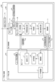
- FIG. 6 is a block diagram showing the functional configuration of the laser processing apparatus according to the second embodiment. Among the components shown in FIG. 6, the components that achieve the same functions as those of the laser processing apparatus 100 of the first embodiment shown in FIG.
- the laser processing device 200 includes a laser processing section 201 and a processing control section 202.
- the laser processing section 201 has the same configuration as the laser processing section 101.
- the processing control section 202 includes a temperature information initialization time setting section 18 in addition to the components included in the processing control section 102.
- the temperature information initialization time setting section 18 is connected to the optical component temperature estimation section 15. Further, the optical component temperature estimating unit 15 of the second embodiment is connected to the laser oscillator 1 and acquires laser output information P4 from an output monitor installed in the laser oscillator 1.
- the laser processing apparatus 200 may process a plurality of the same or different parts from one large workpiece W.
- the temperature of the purge gas in the processing head 3 used by the optical component temperature estimating section 15 may not be cooled down yet, or may be completely cooled down.
- the laser processing apparatus 200 of the second embodiment updates the initial temperature of the purge gas based on the output state of the laser beam L, which affects the temperature of the purge gas.
- the initial temperature of the purge gas is the temperature used to calculate the temperature change component dT cgcenter (i) at the beam center and the temperature change component dT cgedge (i) at the beam end described above.
- the aforementioned temperature change component dT cgcenter (i) at the beam center and temperature change component dT cgedge (i) at the beam end become appropriate values depending on the temperature of the purge gas.
- the temperature information initialization time setting unit 18 sets the initial temperature of the purge gas and the ambient temperature of the processing head 3 when the laser beam L is not oscillated, that is, when the time when the laser output value is 0 [W] continues for a specific time or more. update at least one of the initial temperatures. For example, if the laser output value is 0 [W] for a specific time or more, the temperature information initialization time setting unit 18 issues a command (initial A temperature update command) is output to the optical component temperature estimation section 15. Note that the temperature information initialization time setting unit 18 outputs an initial temperature update command to the optical component temperature estimation unit 15 when the laser output value remains near 0 [W] (less than a specific value) for a specific time or more. It's okay.
- the temperature information initialization time setting unit 18 allows the optical component temperature estimation unit 15 to store the laser output value if it is less than a specific value (for example, 0 [W]) during the set specific time. outputs an initial temperature update command to the optical component temperature estimator 15 to update the temperature of the purge gas that is currently in use to the value of the latest temperature information P5 output by the temperature sensor 7 at this time (when the initial temperature update command is received) .
- a specific value for example, 0 [W]
- the optical component temperature estimation unit 15 Upon receiving the initial temperature update command, the optical component temperature estimation unit 15 updates the currently stored temperature of the purge gas to the value of the latest temperature information P5 output by the temperature sensor 7 when the initial temperature update command is received. do. Then, the optical component temperature estimation section 15 estimates the temperature distribution of the optical component 30 based on the updated temperature information P5 and the beam characteristics received from the beam characteristic calculation section 14.
- the laser processing apparatus 200 may respond to changes in the temperature of the purge gas inside the processing head 3, changes in the temperature of the surrounding environment, etc., and performs processing after estimating the imaging performance adapted to the environment. be able to.
- the time setting for temperature information initialization in the temperature information initialization time setting section 18 may be set by the operator, may be set in advance when starting up the processing control section 202, or may be set in advance by the processing control section 202. 202 may be set at the time of shipment.
- the temperature information initialization time setting unit 18 initializes the deviation amount of the imaging position to 0 [mm] when the laser output value is 0 [W] for a specific time, and changes due to the thermal lens effect. It may have a function of initializing the amount of change in imaging performance. As a result, the laser processing apparatus 200 does not displace the optical component 30 when it does not actually contribute to processing, so it is possible to extend the life of the drive section 10X.
- the laser processing apparatus 200 if the laser processing apparatus 200 has a laser output value of 0 [W] for a specific period of time or more, the temperature of the purge gas is likely to have changed. Update information. Thereby, the laser processing apparatus 200 can accurately estimate the state of the atmosphere within the processing head 3 before starting processing. Therefore, the laser processing apparatus 200 can perform processing after estimating the imaging performance according to the temperature change of the purge gas in the processing head 3, the temperature change of the surrounding environment, etc. Therefore, the laser processing apparatus 200 can sufficiently suppress deterioration of laser processing quality.
- the laser processing apparatus of the third embodiment uses the imaging performance estimated by the imaging performance change estimation unit 17 based on processing type information indicating the type of laser processing such as the material, plate thickness, and processing gas type of the workpiece W. Correct the amount of change.
- FIG. 7 is a block diagram showing the functional configuration of the laser processing apparatus according to the third embodiment. Among the components in FIG. 7, components that achieve the same functions as those of the laser processing apparatus 100 of the first embodiment shown in FIG. 4 are designated by the same reference numerals, and redundant explanations will be omitted.
- the laser processing device 300 includes a laser processing section 301 and a processing control section 302.
- the laser processing section 301 has the same configuration as the laser processing section 101.
- the processing control section 302 includes a correction coefficient determining section 19 in addition to the components included in the processing control section 102 or the processing control section 202. In the following, a case will be described in which the processing control section 302 includes the correction coefficient determining section 19 in addition to the components included in the processing control section 102.
- the machining parameter input unit 13 of the machining control unit 302 outputs information indicating the material of the workpiece W (material P21), information indicating the plate thickness of the workpiece W (plate thickness P22), and processing information used for laser processing from the processing parameter P1.
- Gas type information (gas type P23) is extracted and output to the correction coefficient determination unit 19.
- the processing gas used in laser processing is a gas (assist gas) that is sprayed onto the workpiece W when the workpiece W is irradiated with the laser beam L.
- the correction coefficient determination section 19 is connected to the processing parameter input section 13 and the correction amount calculation section 22.
- the correction coefficient determining unit 19 receives the material P21, plate thickness P22, and gas type P23 from the machining parameter input unit 13 as machining type information.
- the correction coefficient determining unit 19 determines a correction coefficient k corresponding to at least one of the material P21, the plate thickness P22, and the gas type P23.
- the correction coefficient k is a coefficient for correcting the amount of change in imaging performance.
- the correction coefficient determination unit 19 outputs the determined correction coefficient k to the correction amount calculation unit 22.
- the correction amount calculation unit 22 receives the correction coefficient k from the correction coefficient determination unit 19 and also receives the amount of change in imaging performance from the imaging performance change estimation unit 17.
- the correction amount calculation unit 22 multiplies ⁇ f by a correction coefficient k for correcting ⁇ f. , calculate the corrected deviation amount ⁇ f corr .
- the correction amount calculating unit 22 calculates the corrected deviation amount ⁇ f corr using the following equation (10).
- the correction amount calculation unit 22 calculates a correction amount for returning the imaging performance to the state before starting processing, based on the corrected deviation amount ⁇ f corr (imaging performance change amount after correction).
- the correction amount calculation unit 22 outputs the calculated correction amount to the control unit 11.
- the laser processing apparatus 300 determines whether the processing tolerance of the imaging position at the start of processing according to the material P21, the plate thickness P22, and the gas type P23 is in the direction of the processing head 3 rather than the surface of the workpiece W. In some cases, it may be known in advance whether the object is located in the depth direction. In this case, the laser processing apparatus 300 can multiply the deviation amount ⁇ f by a correction coefficient k according to the processing tolerance of the imaging position.
- a correction coefficient k is set such that the imaging position of the imaging point is moved in the direction of the processing head 3. That is allowed. Therefore, in this case, the correction coefficient k that avoids moving the imaging position of the imaging point in the depth direction of the workpiece W is set to a value of, for example, 1.0 or less.
- the laser processing apparatus 300 can correct the imaging performance according to processing type information such as material P21, plate thickness P22, and gas type P23, and can perform processing according to the working environment. Become.
- the correction amount calculation unit 22 calculates the correction amount of the processing parameter P1 based on the corrected imaging performance change amount (corrected deviation amount ⁇ f corr ).
- the correction amount calculation section 22 outputs the correction amount of the processing parameter P1 to the control section 11.
- the control unit 11 adjusts the optical component 30 based on the correction amount so that the evaluation value of the imaging performance becomes constant.
- the control unit 11 inputs a command for adjusting the optical component 30 (such as a movement command for the optical component 30) to the drive unit 10X, thereby performing laser processing while changing the position of the optical component 30 during laser processing. Control. In this way, the control unit 11 executes control corresponding to the imaging performance evaluation value (imaging performance change amount) multiplied by the correction coefficient k.
- the laser processing apparatus 300 corrects the amount of change in imaging performance according to the material P21, the plate thickness P22, and the gas type P23. Thereby, the laser processing apparatus 300 can perform processing after correcting the processing parameter P1 with a correction amount corresponding to the amount of change in imaging performance corrected according to the material P21, plate thickness P22, and gas type P23. can. Therefore, the laser processing apparatus 300 can sufficiently suppress deterioration of laser processing quality.
- the laser processing device creates a learned model by learning the correspondence between processing parameters P1, optical component position information P3, laser output information P4, and temperature information P5 and the amount of change in imaging performance. I'll keep it.
- the laser processing device estimates the amount of change in imaging performance by inputting processing parameters P1, optical component position information P3, laser output information P4, and temperature information P5 into the trained model. do.
- FIG. 8 is a block diagram showing the functional configuration of the laser processing apparatus according to the fourth embodiment.
- the components that achieve the same functions as those of the laser processing apparatus 100 of the first embodiment shown in FIG. 4 are designated by the same reference numerals, and redundant explanations will be omitted.
- the laser processing device 400 includes a laser processing section 401 and a processing control section 402.
- the laser processing section 401 has the same configuration as the laser processing section 101.
- the processing control unit 402 includes a processing parameter analyzer 20, which is a machine learning device, in addition to the components included in the processing control unit 102, the processing control unit 202, or the processing control unit 302. .
- the machining control unit 402 includes the machining parameter analyzer 20 in addition to the components included in the machining control unit 102.
- the processing parameter analyzer 20 includes a data acquisition section 21, a feature amount extraction section 23, a learning section 24, and a correction amount calculation section 22.
- the data acquisition section 21 is connected to the processing parameter input section 13 , the laser oscillator 1 , the temperature sensor 7 , and the feature amount extraction section 23 .
- the learning section 24 is connected to the feature amount extraction section 23 and the correction amount calculation section 22.
- the data acquisition unit 21 acquires the processing parameters P1 and optical component position information P3 from the processing parameter input unit 13.
- the data acquisition unit 21 also acquires temperature information P5 from the temperature sensor 7.
- the data acquisition unit 21 also acquires laser output information P4 from the laser oscillator 1.
- the laser output information P4 here is the first output value of the laser beam L
- the temperature information P5 is the first temperature information.
- the data acquisition unit 21 may extract the laser output information P4 from the processing parameters P1 output from the processing parameter input unit 13, as in the first embodiment. Further, the data acquisition unit 21 may calculate the laser output information P4 from the output command of the laser beam L that is actually output from the control unit 11 to the laser oscillator 1.
- the data acquisition unit 21 acquires a laser output history that is time series data of laser output, and a temperature history that is time series data of measurement results of the temperature sensor 7. Specifically, the data acquisition unit 21 generates a laser output history based on the laser output information P4. Furthermore, the data acquisition unit 21 generates a temperature history based on the temperature information P5.
- the laser output history is a temporal change in laser output.
- the laser output history may be the average output of the laser beam L or may be the peak output.
- the laser output history may be any data that shows temporal changes in output.
- the data acquisition unit 21 acquires the laser output history at a sampling period that the data acquisition unit 21 can obtain.
- the data acquisition unit 21 outputs the acquired processing parameters P1, optical component position information P3, laser output history, and temperature history to the feature quantity extraction unit 23 as state quantities. Note that the data acquisition unit 21 only needs to acquire the first state quantity including at least the laser output information P4 and the temperature information P5 and output it to the feature quantity extraction unit 23. Further, the data acquisition unit 21 may output a state quantity including the laser output information P4 to the feature quantity extraction unit 23 instead of the laser output history. Further, the data acquisition unit 21 may output a state quantity including temperature information P5 to the feature quantity extraction unit 23 instead of the temperature history.
- the feature amount extraction unit 23 extracts feature amounts from the state amounts.
- the feature amounts here include temperature information of the optical component 30, laser output information, processing parameter P1, and the like.
- the feature amount extraction unit 23 outputs the extracted feature amount to the learning unit 24.
- the feature amount corresponds to the beam characteristics and temperature information P5 described in Embodiments 1 to 3.
- the evaluation value of the imaging performance is also input to the learning unit 24.
- the evaluation value of the imaging performance is a value corresponding to the measurement result regarding the amount of change in the imaging point, and may be a continuous value or a discrete value.
- the imaging performance evaluation value determined by the operator may be input to the learning unit 24, or the imaging performance evaluation value calculated by the imaging performance change estimation unit 17 of the first to third embodiments may be input. may be done.
- the evaluation value of the imaging performance determined by the operator may be input from an input means (not shown) or may be received from another device, for example.
- the evaluation value may be a beam waist position, a beam diameter at an imaging position, an amount of spherical aberration, or the like.
- the evaluation value may be the quality of the shape of the beam intensity distribution.
- the learning unit 24 learns by associating the feature quantity extracted by the feature quantity extracting unit 23 with the evaluation value of the imaging performance. That is, the learning unit 24 learns the processing performed by the optical component temperature estimation unit 15, the thermal lens estimation unit 16, and the imaging performance change estimation unit 17. Note that the learning section 24 is realized by a processing circuit similarly to the machining parameter analyzer 20.
- the learning unit 24 generates a learned model by learning a set of input data and result data by machine learning.
- the learning unit 24 here generates a learned model by learning to estimate the correction amount of the machining parameter P1 based on the state quantity. Any algorithm may be used as the machine learning algorithm by the learning unit 24.
- the learning unit 24 can use, for example, a supervised learning algorithm.
- the learning unit 24 performs machine learning on the amount of change in imaging performance (the amount of change in the imaging position, the amount of change in the amount of aberration, etc.) using a data set composed of feature amounts and evaluation values.
- the data set here is data in which feature amounts and evaluation values are associated with each other.
- the learning unit 24 uses the trained model by machine learning to determine changes in processing parameters P1 such as the position of the imaging point according to the feature amount and the amount of displacement in the positional relationship of the optical component 30 included in the processing head 3. presume. Specifically, the learning unit 24 uses the trained model to derive the amount of change in imaging performance according to the feature amount. That is, the learning unit 24 acquires a second state quantity including at least laser output information (second output value) P4 and temperature information (first temperature information) P5 during laser processing, and applies it to the learned model. By inputting the feature amount (second state amount), the imaging performance change amount corresponding to the second state amount is derived. The learning unit 24 outputs the derived imaging performance change amount to the correction amount calculation unit 22.
- processing parameters P1 such as the position of the imaging point according to the feature amount and the amount of displacement in the positional relationship of the optical component 30 included in the processing head 3.
- the learning unit 24 uses the trained model to derive the amount of change in imaging performance according to the feature amount. That is, the learning unit 24 acquires
- the machining parameter analyzer 20 does not need to include the feature extraction unit 23.
- the data acquisition unit 21 outputs the state quantity to the learning unit 24.
- the learning unit 24 performs learning using state quantities instead of feature quantities.
- the correction amount calculation unit 22 calculates the correction amount of the processing parameter P1 based on the imaging performance change amount (estimated amount) sent from the learning unit 24. Note that the correction amount calculation unit 22 acquires the processing parameter P1 set in the control unit 11, and uses the imaging performance change amount sent from the learning unit 24 and the processing parameter P1 currently set in the control unit 11. The correction amount may be calculated based on. The correction amount calculation unit 22 outputs the calculated correction amount to the control unit 11.
- the control unit 11 corrects the processing parameter P1 based on the correction amount received from the correction amount calculation unit 22, and thereby controls the processing. In this way, if there is a difference between the value of the processing parameter P1 corresponding to the estimation result (imaging performance change amount) obtained by the learning unit 24 and the current value of the processing parameter P1, the laser processing apparatus 400 , machining is performed under conditions in which the machining parameter P1 is corrected. The correction of the processing parameter P1 is repeated until the amount of correction output from the learning section 24 (the amount of correction corresponding to the amount of deviation in the amount of change in imaging performance) falls within a specific range.
- the control section 11 outputs a command according to the correction amount to the drive section 10X, thereby making it possible to adjust the processing parameter P1 with high precision. Note that when the correction amount is a correction amount for correcting the position of the processing head 3, the control section 11 outputs a command according to the correction amount to the drive section 10A.
- the processing parameter analyzer 20 learned the relationship between the feature amount and the deviation amount of the imaging performance change amount, but the processing parameter analyzer 20 learned the relationship between the feature amount and the amount of thermal lens. You can also learn. That is, the processing parameter analyzer 20 may learn the processing performed by the optical component temperature estimation section 15 and the thermal lens estimation section 16. In other words, in the laser processing apparatuses 100, 200, and 300, the data acquisition section 21, the feature extraction section 23, and the learning section 24 are arranged as machine learning devices instead of the optical component temperature estimation section 15 and the thermal lens estimation section 16. may be done. In this case, the machine learning device receives the beam characteristics from the beam characteristics calculation unit 14 and receives the temperature information P5 from the temperature sensor 7.
- the machine learning device generates a learned model showing the correspondence between the feature amount (beam characteristics and temperature information P5) and the amount of thermal lens through learning.
- the amount of thermal lens calculated by the operator is input to the machine learning device.
- the machine learning device estimates the thermal lens amount corresponding to the feature amount by inputting the feature amount to this learned model during laser processing. In this way, the machine learning device learns the relationship between the feature amount and the thermal lens amount of the optical component 30, and uses the feature amount instead of the optical component temperature estimation unit 15 and the thermal lens estimation unit 16 during laser processing. Estimate the amount of thermal lens corresponding to .
- the processing parameter analyzer 20 may learn the relationship between the feature amount and the temperature distribution of the optical component 30. That is, the processing parameter analyzer 20 may learn the processing performed by the optical component temperature estimation section 15.
- the data acquisition unit (first data acquisition unit) 21 and the feature amount are used as a machine learning device (first machine learning device) instead of the optical component temperature estimation unit 15.
- An extraction unit 23 and a learning unit (first learning unit) 24 may be arranged.
- the machine learning device receives the first beam characteristic from the beam characteristic calculation unit 14 and receives temperature information (first temperature information) P5 from the temperature sensor 7.
- the machine learning device generates, through learning, a first learned model that indicates the correspondence between the feature quantity (the first state quantity including the beam characteristics and the temperature information P5) and the temperature distribution of the optical component 30.
- the temperature distribution of the optical component 30 calculated by the operator is input to the machine learning device.
- the machine learning device calculates a second state quantity including the second beam characteristic received from the beam characteristic calculation unit 14 and the temperature information (second temperature information) P5 received from the temperature sensor 7, By inputting it into the first learned model, the temperature distribution of the optical component 30 corresponding to the second state quantity is estimated.
- the machine learning device learns the relationship between the feature amount and the temperature distribution of the optical component 30, and calculates the temperature of the optical component 30 corresponding to the feature amount instead of the beam characteristic calculation unit 14 during laser processing. Estimate the distribution.
- the processing parameter analyzer 20 calculates the correspondence between the temperature distribution estimated by the optical component temperature estimation section 15, the optical component position information P3 sent from the beam characteristic calculation section 14, and the beam diameter and the amount of thermal lens. You can learn it. That is, the machining parameter analyzer 20 may learn the processing executed by the thermal lens estimation unit 16.
- the data acquisition unit (second data acquisition unit) 21 and the feature extraction unit are used as a machine learning device (second machine learning device) instead of the thermal lens estimation unit 16. 23 and a learning section (second learning section) 24 may be arranged. In this case, the machine learning device receives the temperature distribution (first estimated temperature) from the optical component temperature estimation unit 15.
- the machine learning device generates a second learned model that indicates the correspondence between the feature quantity (the third state quantity including the temperature distribution estimated by the optical component temperature estimation unit 15) and the thermal lens quantity. generate.
- the amount of thermal lens calculated by the operator is input to the machine learning device.
- the machine learning device inputs the fourth state quantity including the temperature distribution (second estimated temperature) estimated by the optical component temperature estimation unit 15 into the second learned model during laser processing.
- a thermal lens amount corresponding to the fourth state amount is estimated.
- the machine learning device learns the relationship between the temperature distribution, the optical component position information P3, the beam diameter, and the amount of thermal lens of the optical component 30, and uses the information in place of the thermal lens estimation unit 16 during laser processing.
- the amount of thermal lens corresponding to the feature amount is estimated.
- the third state quantity and the fourth state quantity may include the optical component position information P3 and the beam diameter sent from the beam characteristic calculation section 14.
- the processing parameter analyzer 20 may learn the correspondence between the amount of thermal lens estimated by the thermal lens estimation unit 16 and the amount of change in imaging performance or the evaluation value of imaging performance. That is, the processing parameter analyzer 20 may learn the processing executed by the imaging performance change estimation unit 17.
- the data acquisition unit (third data acquisition unit) 21, the characteristics A quantity extraction section 23 and a learning section (third learning section) 24 may be arranged.
- the machine learning device receives the thermal lens amount (first thermal lens amount) from the thermal lens estimation unit 16.
- the machine learning device determines the correspondence relationship between the feature amount (the fifth state amount including the thermal lens amount estimated by the thermal lens estimation unit 16) and the imaging performance change amount or the evaluation value of the imaging performance.
- a third trained model is generated that shows .
- the amount of change in imaging performance or the evaluation value of imaging performance calculated by the operator is input to the machine learning device.
- the machine learning device inputs the sixth state quantity including the thermal lens amount (second thermal lens amount) estimated by the thermal lens estimation unit 16 into the third learned model during laser processing. , the amount of change in imaging performance or the evaluation value of imaging performance corresponding to the sixth state quantity is estimated.
- the machine learning device learns the relationship between the amount of thermal lens and the amount of change in imaging performance or the evaluation value of imaging performance, and instead of the imaging performance change estimation unit 17 during laser processing, An amount of change in imaging performance or an evaluation value of imaging performance corresponding to the feature amount is estimated.
- the processing parameter analyzer 20 may learn the correspondence between the amount of change in imaging performance estimated by the imaging performance change estimation unit 17 and the amount of correction of the processing parameter P1. That is, the machining parameter analyzer 20 may learn the processing executed by the correction amount calculation unit 22.
- a data acquisition unit (fourth data acquisition unit) 21 and a feature extraction unit are used as a machine learning device (fourth machine learning device) instead of the correction amount calculation unit 22.
- 23 and a learning section (fourth learning section) 24 may be arranged.
- the machine learning device receives the amount of change in imaging performance (first estimated amount of change in imaging performance) from the imaging performance change estimation unit 17.
- the machine learning device indicates the correspondence between the feature quantity (the seventh state quantity including the imaging performance change amount estimated by the imaging performance change estimation unit 17) and the correction amount of the processing parameter P1. Generate a fourth trained model. In this case, the correction amount of the machining parameter P1 calculated by the operator is input to the machine learning device.
- the machine learning device converts the eighth state quantity including the imaging performance change amount (second estimated imaging performance change amount) estimated by the imaging performance change estimation unit 17 into a fourth learning By inputting it into the completed model, the correction amount of the machining parameter P1 corresponding to the eighth state quantity is estimated. In this way, the machine learning device learns the relationship between the imaging performance change amount and the correction amount, and estimates the correction amount corresponding to the feature amount instead of the correction amount calculation unit 22 during laser processing.
- the machine learning device may learn the correspondence between the thermal lens amount estimated by the thermal lens estimation unit 16 and the correction amount of the processing parameter P1. Similarly, the machine learning device may learn the correspondence between the temperature distribution estimated by the optical component temperature estimation unit 15 and the correction amount of the processing parameter P1.
- the machine learning device performs at least the processing executed by the optical component temperature estimation section 15, the processing executed by the thermal lens estimation section 16, the processing executed by the imaging performance change estimation section 17, and the processing executed by the correction amount calculation section 22. Learn one.
- the machine learning device may learn the correspondence between the temperature distribution estimated by the optical component temperature estimation unit 15 and the amount of change in imaging performance.
- the learning unit 24 has a learning function that performs machine learning on the relationship between the feature amount and the amount of change in imaging performance, and an inference function that infers the amount of change in imaging performance using the learned model.
- the learning function and the inference function may be realized by separate devices.
- an inference section that outputs an evaluation value using a trained model may be provided separately from the learning section 24.
- the processing parameter analyzer 20 may include an inference section that calculates the amount of change in imaging performance using the learned model trained by the learning section 24.
- the learning section 24 is provided within the machining parameter analyzer 20, but the learning section 24 may be a separate device from the machining parameter analyzer 20.
- the machining parameter analyzer 20 and the learning section 24 may be connected via a network.
- the learning unit 24 may exist on a cloud server.
- the learning unit 24 uses, for example, a neural network model to learn the imaging performance change amount corresponding to the processing parameter P1 and the laser output information P4 by so-called supervised learning.
- supervised learning means that a learning machine is given a large amount of datasets, which are pairs of data of a certain input and a result (label), to learn the features in those datasets and to extract the results from the input. It is machine learning that estimates.
- a neural network consists of an input layer consisting of multiple neurons, an intermediate layer consisting of multiple neurons also called a hidden layer, and an output layer consisting of multiple neurons.
- the intermediate layer may be one layer or two or more layers.
- FIG. 9 is a diagram showing a configuration example of a neural network model according to the fourth embodiment.
- X1, X2, and X3 are input layer neurons
- Y1 and Y2 are intermediate layer neurons
- Z1, Z2, and Z3 are output layer neurons.
- each input value is It is multiplied by w16 and input to intermediate layer neurons Y1 and Y2.
- the output values from Y1 and Y2 are multiplied by the corresponding weights w21 to w26 and input to neurons Z1, Z2, and Z3 of the output layer.
- the output layer adds the input values and outputs the result as an output result.
- the results output from Z1, Z2, and Z3 can be made to correspond to the evaluation results corresponding to each machining defect item. This output result changes depending on the values of weights w11 to w16 and weights w21 to w26.
- weights w11 to w16 and weight w21 are set so that the output result of the neural network approaches the correct imaging performance evaluation result (imaging performance change amount). Learning is performed by adjusting w26.
- the neural network shown in FIG. 9 is an example, and the number of layers of the neural network model and the number of neurons belonging to each layer are not limited to the example shown in FIG. 9.
- the learning unit 24 uses a neural network model to learn the relationship between the laser output information P4, the information of the temperature sensor 7, and the evaluation result of the imaging performance, or the processing parameter P1 to be corrected, by so-called unsupervised learning. You can also do that.
- Unsupervised learning refers to providing only a large amount of input data to the learning unit 24, which learns the distribution of the input data, and learns the distribution of the input data without providing the corresponding supervised output data. This is a method for learning methods such as compression, classification, and formatting. For example, in unsupervised learning, it is possible to cluster input data sets that have similar characteristics.
- prediction of the evaluation result can be realized by setting some criteria and assigning the evaluation result to the result of the clustering or the like so as to optimize the result of the clustering or the like.
- semi-supervised learning in which only part of the data set is input and output, and the rest is only input. This is the case when the data is .
- the learning unit 24 of the fourth embodiment may implement machine learning by semi-supervised learning.
- the learning unit 24 acquires data sets from a plurality of processing parameter analyzers 20, and forms an image based on the combination of the laser output history and the temperature history that is time series data of the measurement results of the temperature sensor 7 (temperature information P5).
- the performance evaluation results may be learned.
- the plurality of machining parameter analyzers 20 may be the machining parameter analyzer 20 of the fourth embodiment.
- the learning unit 24 may acquire data sets from a plurality of machining parameter analyzers 20 used at the same site, or may acquire data sets from a plurality of machining parameter analyzers 20 operating at different sites. You may. Furthermore, it is also possible to add the machining parameter analyzer 20 from which the data set is acquired, or to remove the machining parameter analyzer 20 from which the data set is acquired.
- a learning section is provided separately from the machining parameter analyzer 20, and after this learning section learns using the data set acquired from a certain machining parameter analyzer (first machining parameter analyzer), (a second machining parameter analyzer) and further acquire a data set from this second machining parameter analyzer for relearning.
- the data acquisition unit 21 may also acquire the thickness P22 of the workpiece W, the material P21 of the workpiece W, etc., and include them in the state quantities.
- the feature amount extracting unit 23 includes the thickness P22 of the workpiece W, the material P21 of the workpiece W, etc. in the feature amounts and outputs them to the learning unit 24.
- the learning algorithm used in the learning section 24 deep learning that learns the extraction of the feature values themselves can be used, and the learning section 24 can also use other known methods, such as genetic programming and functional logic programming.
- support vector machine Fisher discriminant method, subspace method, discriminant analysis using Mahalanobis space, etc. may be used to perform machine learning.
- learning algorithms used in the learning unit 24 include decision tree, random forest, logistic regression, k-Nearest Neighbor (kNN), subspace method, and CLAFIC (CLAss-Featuring Information Compression method).
- Isolation Forest LOF (Local Outlier Factor), Boosting, AdaBoost, LogitBoost, One-Class SVM (Support Vector Machine), Gaussian Mixture Model, etc.
- LOF Local Outlier Factor
- Boosting AdaBoost
- LogitBoost One-Class SVM (Support Vector Machine), Gaussian Mixture Model, etc.
- the learning unit 24 performs learning that automatically extracts features, such as deep learning, convolutional neural network (CNN), recurrent neural network (RNN), etc.
- the feature extraction unit 23 may not be provided.
- a processing parameter analyzer 20 may be provided for each imaging performance item, or one processing parameter analyzer 20 may be provided for each imaging performance item.
- the learning unit 24 may search for parameters using a search algorithm such as reinforcement learning or Bayesian search. In this way, by having the processing parameter analyzer 20, the processing control unit 402 can estimate the imaging performance with high accuracy, and can stably perform processing.
- the operations of the fourth embodiment other than those described above are the same as those of the first embodiment.
- the machining parameter analyzer 20 of the fourth embodiment has learned the correspondence between the machining parameter P1, optical component position information P3, laser output information P4, and temperature information P5 and the amount of change in imaging performance. Generating a model. Then, during laser processing, the processing parameter analyzer 20 inputs the processing parameters P1, optical component position information P3, laser output information P4, and temperature information P5 into the learned model to determine the amount of change in imaging performance. is estimated. Thereby, the laser processing apparatus 400 can perform laser processing while taking into account changes in the imaging performance of the imaging optical system 5, and therefore it is possible to sufficiently suppress deterioration in the quality of laser processing.
- processing control unit 102 a processing parameter input section 13, a beam characteristic calculation section 14, an optical component temperature estimation section 15, a thermal lens estimation section 16, an imaging performance change estimation section 17, a correction amount calculation section 22, and a control section 11 , realized by a processing circuit.
- This processing circuit may be a processor and memory that executes a program stored in memory, or may be dedicated hardware.
- the processing circuit is also called a control circuit.
- FIG. 10 is a diagram illustrating an example of the configuration of a processing circuit when the processing circuit included in the processing control unit according to Embodiments 1 to 4 is implemented by a processor and memory.
- a processing circuit 90 shown in FIG. 10 is a control circuit and includes a processor 91 and a memory 92.
- each function of the processing circuit 90 is realized by software, firmware, or a combination of software and firmware.
- Software or firmware is written as a program and stored in memory 92.
- each function is realized by a processor 91 reading and executing a program stored in a memory 92.
- the processing circuit 90 includes a memory 92 for storing a machining control program by which the processing of the machining control unit 102 is eventually executed.
- This machining control program can also be said to be a program for causing the machining control unit 102 to execute each function realized by the processing circuit 90.
- This processing control program may be provided by a storage medium in which the program is stored, or may be provided by other means such as a communication medium.
- the processor 91 is, for example, a CPU (Central Processing Unit), a processing device, an arithmetic device, a microprocessor, a microcomputer, or a DSP (Digital Signal Processor).
- the memory 92 may be a nonvolatile or volatile memory such as RAM (Random Access Memory), ROM (Read Only Memory), flash memory, EPROM (Erasable Programmable ROM), or EEPROM (registered trademark) (Electrically EPROM). This includes semiconductor memory, magnetic disks, flexible disks, optical disks, compact disks, mini disks, and DVDs (Digital Versatile Discs).
- FIG. 11 is a diagram showing an example of a processing circuit in the case where the processing circuit included in the processing control unit according to Embodiments 1 to 4 is configured with dedicated hardware.
- the processing circuit 93 shown in FIG. 11 is, for example, a single circuit, a composite circuit, a programmed processor, a parallel programmed processor, an ASIC (Application Specific Integrated Circuit), an FPGA (Field Programmable Gate Array), or a combination of these. applicable.
- processing circuits 90 and 93 some may be realized by dedicated hardware, and some may be realized by software or firmware. In this way, the processing circuits 90 and 93 can implement the above-mentioned functions using dedicated hardware, software, firmware, or a combination thereof.
- processing parameter input section 13 beam characteristic calculation section 14, optical component temperature estimation section 15, thermal lens estimation section 16, imaging performance change estimation section 17, correction amount calculation section 22, and control section 11 are as follows. It may also be realized by separate processing circuits.
Landscapes
- Physics & Mathematics (AREA)
- Optics & Photonics (AREA)
- Engineering & Computer Science (AREA)
- Plasma & Fusion (AREA)
- Mechanical Engineering (AREA)
- Laser Beam Processing (AREA)
Abstract
Description
図1は、実施の形態1にかかるレーザ加工装置の構成を示す図である。以下では、板状の被加工物であるワークWの上面と平行な面内の2つの軸であって互いに直交する2つの軸をX軸およびY軸とする。また、X軸およびY軸に直交する軸をZ軸とする。例えば、XY平面は水平面であり、Z軸方向は鉛直方向に平行な方向である。なお、ワークWは板状に限らない。









つぎに、図6を用いて実施の形態2について説明する。実施の形態2では、レーザ出力値が0[W]である時間が特定時間以上続く場合、パージガスの温度が変化している可能性が高いので、パージガスの温度情報を更新する。
つぎに、図7を用いて実施の形態3について説明する。実施の形態3のレーザ加工装置は、ワークWの材質、板厚、および加工ガスの種類といったレーザ加工の種類を示す加工種類情報に基づいて、結像性能変化推定部17が推定した結像性能変化量を補正する。

つぎに、図8および図9を用いて実施の形態4について説明する。実施の形態4では、レーザ加工装置が、加工パラメータP1、光学部品位置情報P3、レーザ出力情報P4、および温度情報P5と結像性能変化量との対応関係を学習して学習済みモデルを作成しておく。そして、レーザ加工の際には、レーザ加工装置は、加工パラメータP1、光学部品位置情報P3、レーザ出力情報P4、および温度情報P5を学習済みモデルに入力することで、結像性能変化量を推定する。
Claims (15)
- 加工ヘッドに配置された光学部品に照射されるレーザ光のビーム特性を算出するビーム特性算出部と、
前記加工ヘッド内に配置された温度センサが計測した温度の情報である温度情報と、前記ビーム特性とに基づいて、前記光学部品の推定温度を推定する温度推定部と、
前記推定温度に基づいて、前記光学部品の熱レンズ量を推定する熱レンズ推定部と、
前記熱レンズ量に基づいて前記加工ヘッドの結像光学系の結像性能の加工開始前からの変化量である推定結像性能変化量を推定する結像性能変化推定部と、
前記推定結像性能変化量に基づいて、加工パラメータの補正量を算出する補正量算出部と、
前記レーザ光を用いたレーザ加工を制御するとともに、前記レーザ加工中に前記補正量に基づいて前記加工パラメータを変更する制御部と、
を備える、
ことを特徴とするレーザ加工装置。 - 前記結像性能変化推定部は、
前記結像光学系の加工開始前からの結像点の位置の変化量を前記推定結像性能変化量として推定する、
ことを特徴とする請求項1に記載のレーザ加工装置。 - 前記温度推定部は、
前記光学部品の温度を時系列に複数の時点で推定するとともに、前記光学部品の温度を推定する際には、推定する時点より少なくとも1ステップ前の時点の前記光学部品の温度に基づいて前記光学部品の温度を推定する、
ことを特徴とする請求項1または2に記載のレーザ加工装置。 - 前記温度推定部は、
前記レーザ光のレーザ出力値が特定時間の間、特定値未満となる場合、前記温度センサが計測した前記温度情報を最新の温度情報に更新し、前記最新の温度情報と前記ビーム特性とに基づいて、前記推定温度を推定する、
ことを特徴とする請求項1から3の何れか1つに記載のレーザ加工装置。 - 前記レーザ加工の種類を示す加工種類情報に基づいて、前記推定結像性能変化量を補正する補正係数を決定する補正係数決定部をさらに備え、
前記補正量算出部は、前記補正係数を用いて前記推定結像性能変化量を補正し、補正後の前記推定結像性能変化量に基づいて、前記補正量を算出する、
ことを特徴とする請求項1から4の何れか1つに記載のレーザ加工装置。 - 前記加工種類情報は、被加工物の材質、前記被加工物の板厚、および前記レーザ加工に用いられる加工ガスの種類の少なくとも1つの情報を含んでいる、
ことを特徴とする請求項5に記載のレーザ加工装置。 - 前記温度センサは、前記光学部品を把持する把持部に取り付けられている、
ことを特徴とする請求項1から6の何れか1つに記載のレーザ加工装置。 - 前記温度推定部は、第1の機械学習装置を有し、
前記第1の機械学習装置は、
前記温度情報のうちの第1の温度情報と前記ビーム特性のうちの第1のビーム特性とを含む第1の状態量を取得する第1のデータ取得部と、
前記第1の状態量に基づいて前記推定温度を推定することを学習して第1の学習済みモデルを生成し、前記温度情報のうちの第2の温度情報と前記ビーム特性のうちの第2のビーム特性とを含む第2の状態量、および前記第1の学習済みモデルに基づいて、前記第2の状態量に対応する前記推定温度を推定する第1の学習部と、
を備える、
ことを特徴とする請求項1から7の何れか1つに記載のレーザ加工装置。 - 前記熱レンズ推定部は、第2の機械学習装置を備え、
前記第2の機械学習装置は、
前記推定温度のうちの第1の推定温度を含む第3の状態量を取得する第2のデータ取得部と、
前記第3の状態量に基づいて前記熱レンズ量を推定することを学習して第2の学習済みモデルを生成し、前記推定温度のうちの第2の推定温度を含む第4の状態量、および前記第2の学習済みモデルに基づいて、前記第4の状態量に対応する前記熱レンズ量を推定する第2の学習部と、
を備える、
ことを特徴とする請求項1から8の何れか1つに記載のレーザ加工装置。 - 前記結像性能変化推定部は、第3の機械学習装置を備え、
前記第3の機械学習装置は、
前記熱レンズ量のうちの第1の熱レンズ量を含む第5の状態量を取得する第3のデータ取得部と、
前記第5の状態量に基づいて前記推定結像性能変化量を推定することを学習して第3の学習済みモデルを生成し、前記熱レンズ量のうちの第2の熱レンズ量を含む第6の状態量、および前記第3の学習済みモデルに基づいて、前記第6の状態量に対応する前記推定結像性能変化量を推定する第3の学習部と、
を備える、
ことを特徴とする請求項1から9の何れか1つに記載のレーザ加工装置。 - 前記補正量算出部は、第4の機械学習装置を備え、
前記第4の機械学習装置は、
前記推定結像性能変化量のうちの第1の推定結像性能変化量を含む第7の状態量を取得する第4のデータ取得部と、
前記第7の状態量に基づいて前記補正量を推定することを学習して第4の学習済みモデルを生成し、前記推定結像性能変化量のうちの第2の推定結像性能変化量を含む第8の状態量、および前記第4の学習済みモデルに基づいて、前記第8の状態量に対応する前記補正量を推定する第4の学習部と、
を備える、
ことを特徴とする請求項1から10の何れか1つに記載のレーザ加工装置。 - 加工ヘッドに配置された光学部品に照射されるレーザ光の第1の出力値と、前記加工ヘッド内に配置された温度センサが計測した温度の情報である第1の温度情報とを含む第1の状態量を取得するデータ取得部と、
前記第1の状態量に基づいて加工パラメータの補正量を推定することを学習して学習済みモデルを生成し、前記レーザ光の第2の出力値と、前記温度センサが計測した温度の情報である第2の温度情報とを含む第2の状態量、および前記学習済みモデルに基づいて、前記第2の状態量に対応する前記補正量を推定する学習部と、
前記レーザ光を用いたレーザ加工を制御するとともに、前記レーザ加工中に前記補正量に基づいて前記加工パラメータを変更する制御部と、
を備える、
ことを特徴とするレーザ加工装置。 - 加工ヘッドに配置された光学部品に照射されるレーザ光のビーム特性を算出するビーム特性算出部と、
前記加工ヘッド内に配置された温度センサが計測した温度の情報である温度情報と、前記ビーム特性とに基づいて、前記光学部品の推定温度を推定する温度推定部と、
前記推定温度に基づいて、前記光学部品の熱レンズ量を推定する熱レンズ推定部と、
前記熱レンズ量に基づいて前記加工ヘッドの結像光学系の結像性能の加工開始前からの変化量である推定結像性能変化量を推定する結像性能変化推定部と、
前記推定結像性能変化量に基づいて、加工パラメータの補正量を算出する補正量算出部と、
前記レーザ光を用いたレーザ加工を制御するとともに、前記レーザ加工中に前記補正量に基づいて前記加工パラメータを変更する制御部と、
を備える、
ことを特徴とする制御装置。 - 光学部品が配置された加工ヘッドから被加工物にレーザ光を照射して前記被加工物へのレーザ加工を行うレーザ加工部と、
前記レーザ加工部を制御する加工制御部と、
を有し、
前記レーザ加工部は、
前記レーザ光を発振するレーザ発振器と、
前記加工ヘッド内に配置されて前記加工ヘッド内の温度を計測する温度センサと、
を備え、
前記加工制御部は、
前記光学部品に照射される前記レーザ光のビーム特性を算出するビーム特性算出部と、
前記温度センサが計測した温度の情報である温度情報と、前記ビーム特性とに基づいて、前記光学部品の推定温度を推定する温度推定部と、
前記推定温度に基づいて、前記光学部品の熱レンズ量を推定する熱レンズ推定部と、
前記熱レンズ量に基づいて前記加工ヘッドの結像光学系の結像性能の加工開始前からの変化量である推定結像性能変化量を推定する結像性能変化推定部と、
前記推定結像性能変化量に基づいて、加工パラメータの補正量を算出する補正量算出部と、
前記レーザ光を用いた前記レーザ加工を制御するとともに、前記レーザ加工中に前記補正量に基づいて前記加工パラメータを変更する制御部と、
を備える、
ことを特徴とするレーザ加工システム。 - レーザ加工部が、光学部品が配置された加工ヘッドから被加工物にレーザ光を照射して前記被加工物へのレーザ加工を行うレーザ加工ステップと、
加工制御部が、前記レーザ加工部を制御する加工制御ステップと、
を含み、
前記レーザ加工ステップは、
レーザ発振器が、前記レーザ光を発振するレーザ発振ステップと、
前記加工ヘッド内に配置された温度センサが、前記加工ヘッド内の温度を計測する温度計測ステップと、
を含み、
前記加工制御ステップは、
前記加工制御部が、前記光学部品に照射される前記レーザ光のビーム特性を算出するビーム特性算出ステップと、
前記加工制御部が、前記温度センサが計測した温度の情報である温度情報と、前記ビーム特性とに基づいて、前記光学部品の推定温度を推定する温度推定ステップと、
前記加工制御部が、前記推定温度に基づいて、前記光学部品の熱レンズ量を推定する熱レンズ推定ステップと、
前記加工制御部が、前記熱レンズ量に基づいて前記加工ヘッドの結像光学系の結像性能の加工開始前からの変化量である推定結像性能変化量を推定する結像性能変化推定ステップと、
前記加工制御部が、前記推定結像性能変化量に基づいて、加工パラメータの補正量を算出する補正量算出ステップと、
前記加工制御部が、前記レーザ光を用いた前記レーザ加工を制御するとともに、前記レーザ加工中に前記補正量に基づいて前記加工パラメータを変更する制御ステップと、
を含む、
ことを特徴とするレーザ加工方法。
Priority Applications (5)
| Application Number | Priority Date | Filing Date | Title |
|---|---|---|---|
| JP2022560068A JP7191282B1 (ja) | 2022-04-12 | 2022-04-12 | レーザ加工装置、制御装置、レーザ加工システム、およびレーザ加工方法 |
| PCT/JP2022/017619 WO2023199409A1 (ja) | 2022-04-12 | 2022-04-12 | レーザ加工装置、制御装置、レーザ加工システム、およびレーザ加工方法 |
| CN202280094126.2A CN118984752A (zh) | 2022-04-12 | 2022-04-12 | 激光加工装置、控制装置、激光加工系统及激光加工方法 |
| US18/854,574 US20250326049A1 (en) | 2022-04-12 | 2022-04-12 | Laser machining apparatus, control device, laser machining system, and laser machining method |
| DE112022007031.5T DE112022007031T5 (de) | 2022-04-12 | 2022-04-12 | Laserbearbeitungseinrichtung, steuervorrichtung, laserbearbeitungssystem und laserbearbeitungsverfahren |
Applications Claiming Priority (1)
| Application Number | Priority Date | Filing Date | Title |
|---|---|---|---|
| PCT/JP2022/017619 WO2023199409A1 (ja) | 2022-04-12 | 2022-04-12 | レーザ加工装置、制御装置、レーザ加工システム、およびレーザ加工方法 |
Publications (1)
| Publication Number | Publication Date |
|---|---|
| WO2023199409A1 true WO2023199409A1 (ja) | 2023-10-19 |
Family
ID=84488890
Family Applications (1)
| Application Number | Title | Priority Date | Filing Date |
|---|---|---|---|
| PCT/JP2022/017619 Ceased WO2023199409A1 (ja) | 2022-04-12 | 2022-04-12 | レーザ加工装置、制御装置、レーザ加工システム、およびレーザ加工方法 |
Country Status (5)
| Country | Link |
|---|---|
| US (1) | US20250326049A1 (ja) |
| JP (1) | JP7191282B1 (ja) |
| CN (1) | CN118984752A (ja) |
| DE (1) | DE112022007031T5 (ja) |
| WO (1) | WO2023199409A1 (ja) |
Cited By (1)
| Publication number | Priority date | Publication date | Assignee | Title |
|---|---|---|---|---|
| CN119009633A (zh) * | 2024-10-18 | 2024-11-22 | 河北大学 | 一种激光功率密度调节装置 |
Families Citing this family (2)
| Publication number | Priority date | Publication date | Assignee | Title |
|---|---|---|---|---|
| JP2024120226A (ja) * | 2023-02-24 | 2024-09-05 | 株式会社Screenホールディングス | 推定方法、制御方法および制御装置 |
| DE102023113280A1 (de) * | 2023-05-22 | 2024-11-28 | Precitec Gmbh & Co. Kg | Laserbearbeitungssystem und Verfahren zum Betreiben eines Laserbearbeitungssystems |
Citations (3)
| Publication number | Priority date | Publication date | Assignee | Title |
|---|---|---|---|---|
| JP2006088163A (ja) * | 2004-09-21 | 2006-04-06 | Fanuc Ltd | レーザ装置 |
| JP2020175425A (ja) * | 2019-04-19 | 2020-10-29 | ファナック株式会社 | レーザ加工機の焦点位置ずれを学習する機械学習装置及び機械学習方法、並びに焦点位置ずれを補正するレーザ加工システム |
| WO2022044209A1 (ja) * | 2020-08-27 | 2022-03-03 | 三菱電機株式会社 | レーザ加工装置 |
Family Cites Families (1)
| Publication number | Priority date | Publication date | Assignee | Title |
|---|---|---|---|---|
| JP2000094173A (ja) | 1998-09-18 | 2000-04-04 | Nippei Toyama Corp | レーザ加工機におけるレーザビームの焦点位置調節装置及び調節方法 |
-
2022
- 2022-04-12 DE DE112022007031.5T patent/DE112022007031T5/de active Pending
- 2022-04-12 WO PCT/JP2022/017619 patent/WO2023199409A1/ja not_active Ceased
- 2022-04-12 JP JP2022560068A patent/JP7191282B1/ja active Active
- 2022-04-12 US US18/854,574 patent/US20250326049A1/en active Pending
- 2022-04-12 CN CN202280094126.2A patent/CN118984752A/zh active Pending
Patent Citations (3)
| Publication number | Priority date | Publication date | Assignee | Title |
|---|---|---|---|---|
| JP2006088163A (ja) * | 2004-09-21 | 2006-04-06 | Fanuc Ltd | レーザ装置 |
| JP2020175425A (ja) * | 2019-04-19 | 2020-10-29 | ファナック株式会社 | レーザ加工機の焦点位置ずれを学習する機械学習装置及び機械学習方法、並びに焦点位置ずれを補正するレーザ加工システム |
| WO2022044209A1 (ja) * | 2020-08-27 | 2022-03-03 | 三菱電機株式会社 | レーザ加工装置 |
Cited By (1)
| Publication number | Priority date | Publication date | Assignee | Title |
|---|---|---|---|---|
| CN119009633A (zh) * | 2024-10-18 | 2024-11-22 | 河北大学 | 一种激光功率密度调节装置 |
Also Published As
| Publication number | Publication date |
|---|---|
| DE112022007031T5 (de) | 2025-02-20 |
| JPWO2023199409A1 (ja) | 2023-10-19 |
| CN118984752A (zh) | 2024-11-19 |
| JP7191282B1 (ja) | 2022-12-16 |
| US20250326049A1 (en) | 2025-10-23 |
Similar Documents
| Publication | Publication Date | Title |
|---|---|---|
| JP7191282B1 (ja) | レーザ加工装置、制御装置、レーザ加工システム、およびレーザ加工方法 | |
| US11167377B2 (en) | Machining condition setting device and 3D laser machining system | |
| CN107199397B (zh) | 机器学习装置、激光加工系统以及机器学习方法 | |
| US10643127B2 (en) | Machine learning apparatus for learning condition for starting laser machining, laser apparatus, and machine learning method | |
| US12269122B2 (en) | Method, control unit and laser cutting system for combined path and laser process planning for highly dynamic real-time systems | |
| US10376988B2 (en) | Laser processing robot system and laser processing method | |
| US11565344B2 (en) | Device and method for learning focal position offset of laser processing apparatus, and laser processing system correcting focal position offset | |
| CN109420859B (zh) | 机器学习装置、机器学习系统以及机器学习方法 | |
| JP5012732B2 (ja) | エネルギビームによる焼入方法および焼入システム | |
| US11097375B2 (en) | Laser processing apparatus and laser processing method | |
| JP2012533434A (ja) | レーザ加工ヘッドおよびレーザ加工ヘッドの焦点位置の変化を補償するための方法 | |
| KR20200110812A (ko) | 레이저 가공 장치 및 레이저 가공 방법 | |
| CN114131200B (zh) | 一种激光-电弧复合焊接的过程控制方法、系统及装置 | |
| Baraldo et al. | Closed-loop control by laser power modulation in direct energy deposition additive manufacturing | |
| US12479050B2 (en) | Laser irradiation apparatus, information processing method, and recording medium recording program to be readable | |
| JP6810110B2 (ja) | 加工条件調整装置及び機械学習装置 | |
| JP7174934B2 (ja) | レーザ光照射装置及びレーザ光照射方法 | |
| KR20180129280A (ko) | 3차원 적층 가공의 실시간 가공 상태 검사와 보정 장치 및 이를 적용한 방법 | |
| CN114442482A (zh) | 利用人工智能来求取激光焊接的能量输入的方法和设备 | |
| Biswas et al. | Effects of process parameters on hole circularity and taper in pulsed Nd: YAG laser microdrilling of Tin-Al2O3 composites | |
| US20230321750A1 (en) | Laser machining apparatus | |
| JP7415097B1 (ja) | 制御装置、レーザ加工システム、およびレーザ加工方法 | |
| JP2016010819A (ja) | レーザ加工装置 | |
| JPH06285661A (ja) | レーザ加工機 | |
| Cerwenka et al. | Focus shift control of a novel 30 kW laser remote scanner for large-scale industrial sheet and plate metal applications |
Legal Events
| Date | Code | Title | Description |
|---|---|---|---|
| WWE | Wipo information: entry into national phase |
Ref document number: 2022560068 Country of ref document: JP |
|
| 121 | Ep: the epo has been informed by wipo that ep was designated in this application |
Ref document number: 22937388 Country of ref document: EP Kind code of ref document: A1 |
|
| WWE | Wipo information: entry into national phase |
Ref document number: 202280094126.2 Country of ref document: CN |
|
| WWE | Wipo information: entry into national phase |
Ref document number: 18854574 Country of ref document: US |
|
| WWE | Wipo information: entry into national phase |
Ref document number: 112022007031 Country of ref document: DE |
|
| WWP | Wipo information: published in national office |
Ref document number: 112022007031 Country of ref document: DE |
|
| 122 | Ep: pct application non-entry in european phase |
Ref document number: 22937388 Country of ref document: EP Kind code of ref document: A1 |
|
| WWP | Wipo information: published in national office |
Ref document number: 18854574 Country of ref document: US |