WO2023195354A1 - ガラス振動板、及び振動子付きガラス振動板 - Google Patents
ガラス振動板、及び振動子付きガラス振動板 Download PDFInfo
- Publication number
- WO2023195354A1 WO2023195354A1 PCT/JP2023/011664 JP2023011664W WO2023195354A1 WO 2023195354 A1 WO2023195354 A1 WO 2023195354A1 JP 2023011664 W JP2023011664 W JP 2023011664W WO 2023195354 A1 WO2023195354 A1 WO 2023195354A1
- Authority
- WO
- WIPO (PCT)
- Prior art keywords
- glass
- vibrator
- mount
- glass plate
- plate structure
- Prior art date
- Legal status (The legal status is an assumption and is not a legal conclusion. Google has not performed a legal analysis and makes no representation as to the accuracy of the status listed.)
- Ceased
Links
Images












Classifications
-
- H—ELECTRICITY
- H04—ELECTRIC COMMUNICATION TECHNIQUE
- H04R—LOUDSPEAKERS, MICROPHONES, GRAMOPHONE PICK-UPS OR LIKE ACOUSTIC ELECTROMECHANICAL TRANSDUCERS; ELECTRIC HEARING AIDS; PUBLIC ADDRESS SYSTEMS
- H04R1/00—Details of transducers, loudspeakers or microphones
- H04R1/02—Casings; Cabinets ; Supports therefor; Mountings therein
-
- H—ELECTRICITY
- H04—ELECTRIC COMMUNICATION TECHNIQUE
- H04R—LOUDSPEAKERS, MICROPHONES, GRAMOPHONE PICK-UPS OR LIKE ACOUSTIC ELECTROMECHANICAL TRANSDUCERS; ELECTRIC HEARING AIDS; PUBLIC ADDRESS SYSTEMS
- H04R1/00—Details of transducers, loudspeakers or microphones
- H04R1/06—Arranging circuit leads; Relieving strain on circuit leads
-
- H—ELECTRICITY
- H04—ELECTRIC COMMUNICATION TECHNIQUE
- H04R—LOUDSPEAKERS, MICROPHONES, GRAMOPHONE PICK-UPS OR LIKE ACOUSTIC ELECTROMECHANICAL TRANSDUCERS; ELECTRIC HEARING AIDS; PUBLIC ADDRESS SYSTEMS
- H04R7/00—Diaphragms for electromechanical transducers; Cones
- H04R7/02—Diaphragms for electromechanical transducers; Cones characterised by the construction
-
- H—ELECTRICITY
- H04—ELECTRIC COMMUNICATION TECHNIQUE
- H04R—LOUDSPEAKERS, MICROPHONES, GRAMOPHONE PICK-UPS OR LIKE ACOUSTIC ELECTROMECHANICAL TRANSDUCERS; ELECTRIC HEARING AIDS; PUBLIC ADDRESS SYSTEMS
- H04R7/00—Diaphragms for electromechanical transducers; Cones
- H04R7/02—Diaphragms for electromechanical transducers; Cones characterised by the construction
- H04R7/04—Plane diaphragms
Definitions
- the present invention relates to a glass diaphragm and a glass diaphragm with a vibrator.
- Patent Documents 1 to 5 disclose various structures that transmit the vibrations of an electrically vibrating exciter (vibrator) to a diaphragm such as a glass plate.
- Patent Document 1 discloses that a sole, a base, and an attachment are laminated in this order on the main surface of a glass plate, the sole and the base are fixed by a plastic part that covers a part of the glass plate, and the attachment is mounted on the fixed base. discloses a structure for connecting vibrators. In particular, regarding the connection structure between the attachment and the vibrator, fixing means such as a screw structure, a grip structure, a notch structure, and a hook structure are disclosed.
- the mounting structure for mounting such a vibrator on a glass plate requires that its mounting state not change due to continued use of the vibrating vibrator.
- the attachment state of the vibrator changes such as when the vibrator is loosened from being fastened to the glass plate
- individual differences occur in the sound reproducibility of the speakers.
- an object of the present invention is to provide a glass diaphragm and a glass diaphragm with a vibrator that have a structure that makes it easy to confirm the fastening state of the vibrator to the glass plate and correct the fastening state.
- the present invention consists of the following configuration.
- a glass plate structure a mount portion fixed to the glass plate structure and capable of attaching a vibrator that vibrates the glass plate structure; an identification part that is provided on at least one of the mount part and the glass plate structure and indicates a position or a fastened state where the vibrator is fastened to the glass plate structure via the mount part.
- Glass diaphragm Glass diaphragm.
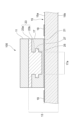
- FIG. 1 is a sectional view of a main part of a glass diaphragm with a vibrator according to a first configuration example.
- FIG. 2 is an external perspective view showing the main parts of the glass diaphragm.
- FIG. 3 is an exploded perspective view showing a fastening structure between the connecting portion and the mount portion in the first configuration example.
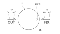
- FIG. 4A is a plan view showing the relationship between the vibrator and the identification section when the glass plate structure is viewed from above.
- FIG. 4B is a plan view showing the relationship between the vibrator and the identification section when the glass plate structure is viewed from above.
- FIG. 5 is a cross-sectional view of a glass diaphragm with a vibrator according to a second configuration example.
- FIG. 6 is a schematic cross-sectional view of a mount portion provided with a plunger as a convex portion.
- FIG. 7A is a side view of the connection section.
- FIG. 7B is a bottom view of the connection part.
- FIG. 8A is a partial cross-sectional view showing a fixed convex portion that protrudes radially inward from the inner peripheral surface of the hole of the mount portion.
- FIG. 8B is a partial cross-sectional view showing another fixed convex portion that protrudes radially inward from the inner peripheral surface of the hole of the mount portion.
- FIG. 9 is an explanatory diagram showing a shaft portion of a connecting portion in which a recessed portion having a barbed structure is formed.
- FIG. 10 is a partially sectional side view showing the connection part and the mount part.
- FIG. 11 is an explanatory diagram showing a shaft portion of a connecting portion in which a concave portion is formed with another return structure.
- FIG. 12 is an exploded perspective view showing a fastening structure between a connecting portion and a mount portion in a third configuration example.
- FIG. 13 is a sectional view of a main part of a glass diaphragm with a vibrator according to a fourth configuration example in which an identification part is provided in a mount part.
- FIG. 14 is an external perspective view showing a main part of the glass diaphragm with a vibrator shown in FIG. 13.
- FIG. 14 is an external perspective view showing a main part of the glass diaphragm with a vibrator shown in FIG. 13.
- FIG. 15A is an exploded view of the mount section, the vibrator, and the connection section, and is an explanatory diagram showing an example of wiring of the light emitting element.
- FIG. 15B is an exploded view of the mount section, the vibrator, and the connection section, and is an explanatory diagram showing an example of wiring of the light emitting element.
- FIG. 16 is a schematic plan view showing an identification section when a vibrator is fastened to a mount section of another shape.
- FIG. 17A is a plan view showing the configuration and operation of a glass diaphragm with a vibrator according to a fifth configuration example.
- FIG. 17B is a plan view showing the configuration and operation of a glass diaphragm with a vibrator according to a fifth configuration example.
- FIG. 18 is a cross-sectional view taken along line XVIII-XVIII in FIG. 17B.
- FIG. 19A is a schematic cross-sectional view showing the arrangement relationship among the mount section, the connection section, and the conductive terminal.
- FIG. 19B is a schematic cross-sectional view showing the arrangement relationship among the mount section, the connection section, and the conductive terminal.
- FIG. 20A is a schematic perspective view showing the configuration and operation of a glass diaphragm with a vibrator in a modification of the fifth configuration example.
- FIG. 20B is a schematic perspective view showing the configuration and operation of a glass diaphragm with a vibrator in a modification of the fifth configuration example.
- FIG. 20A is a schematic perspective view showing the configuration and operation of a glass diaphragm with a vibrator in a modification of the fifth configuration example.
- FIG. 20B is a schematic perspective view showing the configuration and operation of a glass diaphragm with a vibrator in a modification
- FIG. 21A is a schematic perspective view showing the configuration and operation of a glass diaphragm with a vibrator in a modification of the fifth configuration example.
- FIG. 21B is a schematic perspective view showing the configuration and operation of a glass diaphragm with a vibrator in a modified example of the fifth configuration example.
- FIG. 22 is a schematic plan view showing the configuration of a glass diaphragm with a vibrator in a modified example of the fifth configuration example.
- FIG. 23 is an enlarged plan view of the portion where the vibrator is arranged in FIG. 22.
- FIG. 24 is a side view seen from direction P2 in FIG. 23.
- FIG. 25 is a cross-sectional view showing the configuration of a glass diaphragm with a vibrator according to a sixth configuration example.
- FIG. 26 is a cross-sectional view showing the structure of a glass diaphragm with a vibrator according to a seventh structure example.
- FIG. 27 is a sectional view showing a modification of the vibrator-equipped glass diaphragm shown in FIG. 26.
- FIG. 28 is a sectional view showing the structure of a glass diaphragm with a vibrator according to an eighth structure example.
- the glass diaphragm with a vibrator of this embodiment includes a glass diaphragm and a vibrator that vibrates the glass diaphragm, and can be applied to, for example, vibrating a glass plate for a vehicle.
- a glass diaphragm with a vibrator is applied to a window such as a side window of a vehicle, but the applicable uses are not limited to this.
- FIG. 1 is a sectional view of a main part of a glass diaphragm with a vibrator according to a first configuration example.
- FIG. 2 is an external perspective view showing the main parts of the glass diaphragm.
- the glass diaphragm 100 with a vibrator includes a vibrator 11 and a glass diaphragm 13.
- the vibrator 11 generates sound by imparting vibration to the glass diaphragm 13, and produces an acoustic effect such as generating desired sound inside the vehicle, for example.
- the vibrator 11 used here includes an exciter that includes a coil section electrically connected to an external device, a magnetic circuit section, and an excitation section.
- Glass diaphragm 13 includes a glass plate structure 15 , a mount section 17 , and an identification section 19 . Further, the glass diaphragm 13 may include a connecting portion 23 that firmly fixes the vibrator 11.
- the glass plate structure 15 is a single glass plate having one principal surface (also referred to as a first principal surface) 15a and the other principal surface (also referred to as a second principal surface) 15b, or a plurality of plates bonded together as described below. Any type of laminated glass may be used. Details of the glass plate structure 15 will be described later.
- the mount part 17 is fixed to the glass plate structure 15, and a vibrator 11 that vibrates the glass plate structure 15 can be attached thereto.
- one side is fixed to the main surface 15a of the glass plate structure 15 with an adhesive layer (adhesive material) 21, and the vibrator 11 is attached to the other side via the connection section 23.
- the connecting portion 23 is provided between the vibrator 11 and the mount portion 17, and the vibrator 11 is fixed with screws, adhesive, or the like.
- the connecting portion 23 may be configured to be made of a different member from the casing of the vibrator 11 and firmly fixed thereto, or may be configured to be made of the same member as the casing of the vibrator 11 and integrated.
- the identification part 19 is provided on at least one of the mount part 17 and the glass plate structure 15, and has a function of making it possible to identify the state in which the vibrator 11 is connected via the connection part 23 and the mount part 17.
- the identification portion 19 shown in FIG. 2 is a mark M1 (arrow, etc.) and characters M2 (“FIX”, “OUT”, etc.) marked on the surface of the glass plate structure 15. Further, a mark M3 (triangular mark) may be marked on the surface of the vibrator 11.
- the mark M3 of the vibrator 11 functions as one of the identification parts 19 indicating the rotational position of the vibrator 11.
- FIG. 3 is an exploded perspective view showing a fastening structure between the connecting portion 23 and the mount portion 17 in the first configuration example.
- the mount portion 17 is shown in a partial cross section cut in half.
- the mount portion 17 and the connecting portion 23 can be detachably engaged with each other.
- the connecting portion 23 includes a disk-shaped flange portion 23a that supports the cylindrical vibrator 11, and a cylindrical shaft portion 23b that has a smaller diameter than the flange portion 23a and projects toward the mount portion 17. has.
- the mount portion 17 is formed with a hole 17a into which the shaft portion 23b of the connection portion 23 is inserted.
- the inner peripheral surface of the hole 17a is circular in plan view of the glass plate structure 15.
- the inner diameter of the hole 17a and the outer diameter of the shaft 23b are such that they can slide against each other when the shaft 23b is inserted into the hole 17a. That is, the shaft portion 23b of the connecting portion 23 can be rotatably inserted into the hole portion 17a of the mount portion 17.
- a pair of convex portions 27 are provided on the outer peripheral surface (wall surface) of the shaft portion 23b of the connecting portion 23 so as to protrude in the radial direction.
- a pair of recesses 25 are spirally formed on the inner circumferential surface of the hole 17a of the mount portion 17 to engage and guide the convex portion 27.
- FIG. 3 mainly shows the recessed portion 25 of half the circumference.
- the pair of recesses 25 serve as guide grooves that guide the pair of protrusions 27 provided on the connecting portion 23, respectively, and the recesses 25 and the protrusions 27 constitute a guide mechanism.
- the connecting portion 23 may have a shape other than a columnar shape as long as the convex portion 27 has a rotational structure that allows the convex portion 27 to rotate while sliding in the concave portion 25 .
- the shaft part 23b of the connecting part 23 is attached to the mount part 17 fixed to the glass plate structure 15.
- the convex portion 27 of the shaft portion 23b is aligned with the concave portion 25 of the mount portion 17 on the vibrator 11 side (top side in FIG. 3).
- the connecting portion 23 is rotated clockwise relative to the mount portion 17. This rotational movement causes the convex portion 27 to move along the concave portion 25, and the connecting portion 23 is drawn into the hole portion 17a.
- the connecting portion 23 is fastened to the mount portion 17, and the vibrator 11 is placed in the glass plate structure 15.
- FIG. 4A and 4B are plan views showing the relationship between the vibrator 11 and the identification section 19 when the glass plate structure 15 is viewed from above.
- the rotational position at which the connecting portion 23 is fastened to the mount portion 17 is structurally known.
- the identification part 19 is a part that displays the rotational position of the fastening so that it can be visually determined. That is, the connecting part 23 is rotated clockwise around its axis, and as shown in FIG. 4A, the connecting part 23 is rotated to the fastening side rotation position indicated by the identification part 19 (the position indicated by the "FIX" side arrow).
- this rotational position is the above-described rotational position at which the vibration is fastened. That is, the rotational position at which the connection part 23 is fastened to the mount part 17 is known, and the mark M3 of the vibrator 11 is provided in correspondence with the rotational position at which the connection is completed.
- the identification part 19 on the release side and the mark M3 are provided so that the rotational positions of the identification part 19 on the release side and the mark M3 match.
- the rotational position on the engagement side and the rotational position on the release side are reversed by 180°.
- the identification portion 19 only needs to be provided at least at the rotational position on the engagement side (“FIX” side), and may be omitted at the rotational position on the engagement release side (“OUT” side).
- the identification unit 19 may have a form in which the above-described characters and marks are marked on the glass plate structure 15 by printing, a form in which a sticker on which the characters and marks are printed are pasted on the glass plate structure 15, or a form in which the above-mentioned characters and marks are attached to the glass plate structure 15.
- the surface may be engraved by sandblasting or the like.
- the identification portion 19 may be provided on one main surface 15a of the glass plate structure 15 shown in FIG. 1 on the side to which the vibrator 11 is attached, or may be provided on the other main surface 15b.
- a color that is easy to apply and has good visibility that is different from the color of the surrounding members can be easily selected; for example, black ceramics may be used.
- stamping there is no risk of deterioration such as discoloration or peeling, and the design can be improved.
- the operation of fastening and releasing the fastening between the connecting part 23 to which the vibrator 11 is fixed and the mount part 17 is a simple rotational movement along the guide mechanism formed by the recessed part 25 and the convex part 27. You can improve your sexuality. Further, according to this configuration, there is no need for adhesive to connect the connecting portion 23 and the mount portion 17, and even when the vibrator 11 is replaced due to a malfunction, the mount portion 17 can be connected to the vibrator 11 in a non-destructive state. can be attached and detached. In this way, the vibrator 11 can be easily replaced and maintenance efficiency can be improved.
- the fastening force between the connecting part 23 and the mount part 17 is always constant, and errors in the fastening force during the fastening work are less likely to occur. Whether or not the connecting portion 23 and the mount portion 17 are securely connected can be easily determined by visual inspection using the identification portion 19 as a reference. Furthermore, even if the fastened state becomes loose, the fastened state can be easily corrected, which facilitates quality assurance of products to which the vibrator-equipped glass diaphragm 100 is applied.
- the fastening position of the connecting portion 23 to which the vibrator 11 is fixed is always at the same rotational position, the conductive wire attached to the vibrator 11 is always pulled out in a fixed direction when the vibrator 11 is in the fastened state. Therefore, there is no individual difference in the position of the conductive wire. Therefore, the direction in which the conductive wire is pulled out can be fixed in a direction that avoids interference with surrounding members, and damage to the conductive wire can be prevented.
- FIG. 5 is a cross-sectional view of a glass diaphragm with a vibrator according to a second configuration example.
- the glass diaphragm 200 with a vibrator of the second configuration example has a combination of the concave portion 25 of the mount portion 17 and the convex portion 27 of the connection portion 23 of the glass diaphragm 100 with a vibrator of the first configuration example described above. It is the same as the glass diaphragm 100 with a vibrator of the first configuration example except that the combination is changed to a convex portion 27A of 17A and a concave portion 25A of a connecting portion 23A.
- the same or corresponding parts or members will be given the same or corresponding reference numerals, thereby omitting redundant explanation.
- the mount portion 17A of this configuration includes a convex portion 27A that engages with a concave portion 25A formed in the connecting portion 23A.
- a plunger can be used as the convex portion 27A.
- FIG. 6 is a schematic cross-sectional view of a mount portion 17A in which a plunger 31 is provided as a convex portion 27A.
- the plunger 31 has a spring 33 built into its main body and a contact 35 such as a ball or pin at its tip.
- the contactor 35 sinks into the main body, and when the load is released, it returns to its original position by the restoring force of the spring 33. return.
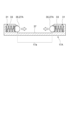
- FIG. 7A is a side view of the connecting portion 23A.
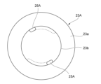
- FIG. 7B is a bottom view of the connecting portion 23A.
- a spiral recess 25A is formed on the outer circumferential surface of the connecting portion 23A along the outer circumferential surface of the shaft portion 23b.
- the contactor 35 which is the convex portion 27A, fits into the recessed portion 25A, and by rotating the vibrator 11 and the connecting portion 23, the contactor 35 slides along the recessed portion 25. Then, the distal end surface 36 of the shaft portion 23b touches the bottom surface 37 (FIG. 6) of the hole 17a of the mount portion 17A, and the connecting portion 23A is fastened to the mount portion 17A.
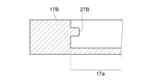
- FIGS. 8A and 8B are partial cross-sectional views showing another fixed convex portion that protrudes radially inward from the inner circumferential surface of the hole 17a of the mount portion.
- the cross-sectional shape of the hole portion 17a along the axial direction may be approximately rectangular like the convex portion 27B of the mount portion 17B shown in FIG. 8A, or may be curved (like the convex portion 27C of the mount portion 17C shown in FIG. 8B). semicircular shape).
- the shape of the recessed portion 25 described above is an example, and is not limited to this.
- the plunger 31 since the contact 35 can be prevented from protruding from the inner circumferential surface of the hole 17a, the recess 25A shown in FIGS. It is also possible to have a configuration in which it is provided only in the vicinity of the fastening position instead of being provided continuously up to the point where it is connected.
- FIG. 9 is an explanatory diagram showing the shaft portion 23b of the connecting portion 23B in which the recessed portion 25B having a turned structure is formed.
- the recessed portion 25B formed in the shaft portion 23b has a retracting portion 25B1 whose height position gradually increases along the circumferential direction of the shaft portion 23b, and a return portion 25B2 whose height position gradually decreases from a specific rotational position Rr.
- FIG. 10 is a partially sectional side view showing the connecting portion 23B and the mount portion 17D.
- the mount portion 17D is provided with an elastic portion 39 such as a coil spring that pushes back the shaft portion 23b of the connecting portion 23B to be inserted.
- the elastic portion 39 has one end fixed to the bottom surface 37 of the hole 17a, and the other end abutting the plate 41 inserted into the hole 17a, so that the end surface 36 of the shaft portion 23b to be inserted is pushed through the plate 41. Force it to push back.
- the vibrator 11 and the connecting portion 23B can be held at the rotational position that is the fastening position with the mount portion 17D. Further, if the vibrator 11 and the connecting portion 23B are rotated counterclockwise against the biasing force of the elastic portion 39, the convex portion 27B returns to the retracting portion 25B1 side, and the connecting portion 23B and the mount portion 17D are The contract can be canceled.
- FIG. 11 is an explanatory diagram showing the shaft portion 23b of the connecting portion 23C in which a recessed portion 25C having another bent structure is formed.
- the recessed portion 25C has a retracting portion 25C1 whose height gradually increases along the circumferential direction of the shaft portion 23b, and a return portion 25C2 formed along the axial direction from a specific rotational position Rr.
- the connecting part 23C is pushed back in the opposite direction to the insertion direction by the elastic repulsive force of the elastic part 39, and the convex part 27B is pushed back to the terminal end of the returned part 25C2. placed in the department. This position becomes the fastening position between the connecting portion 23C and the mount portion 17D.
- the connecting portions 23B, 23C can be stopped from rotating at the fastening position with the mount portion 17A.
- the rotational resistance was maximum just before the fastening position, and even if an attempt was made to rotate it further, the rotational resistance was maximum. Rotation is stopped in position.
- the convex portion 27B reaches the rotation stop position, the connecting portions 23B and 23C are urged by the elastic repulsion force of the elastic portion 39, so that the clockwise and counterclockwise rotations of the connecting portions 23B and 23C are restricted. .
- FIG. 12 is an exploded perspective view showing a fastening structure between the connecting portion 23D and the mount portion 17E in the third configuration example.
- a male thread 43 is formed in the shaft portion 23b of the connecting portion 23D
- a female thread 45 is formed in the hole portion 17a of the mount portion 17E.
- the connecting portion 23D can be fastened to the mount portion 17E. Since the rotational position at which the connecting portion 23D is fastened to the mount portion 17E is known, the identification portion described above is provided at the rotational position at which the connection portion 23D is fastened, although not shown.
- the fastening position can be easily adjusted by combining commercially available parts such as washers and nuts.
- FIG. 13 is a sectional view of a main part of a glass diaphragm 210 with a vibrator according to a fourth configuration example in which an identification part is provided in a mount part.
- FIG. 14 is an external perspective view showing main parts of the vibrator-equipped glass diaphragm 210 shown in FIG. 13.
- the mount portion 17F of this configuration is formed to have a larger diameter than the vibrator 11 and the connecting portion 23E in a plan view of the glass plate structure 15, and the top surface of the portion that projects outward in the radial direction.
- a light emitting element 51 serving as the identification section 19 is arranged at 17b.
- the vibrator 11 and the connecting portion 23E are firmly fixed with adhesive or the like and integrated so that they can rotate together.
- the fixing of both is not limited to adhesive, but may be other forms such as mechanical fastening, a combination of adhesive and mechanical fastening, or integral molding of the package portion of the vibrator 11 and the connecting portion 23E.
- mechanical fastening include known fastening forms such as fastening using screws, screws, etc., and fixing using a clamp mechanism.
- the connecting portion 23E is fastened to the mount portion 17F via the concave portion 25 and the convex portion 27.
- the connecting portion 23E and the mount portion 17F may be fastened together in a manner other than the above-mentioned configuration, in which the mount portion 17F is provided with a convex portion and the connecting portion 23E is provided with a recessed portion.
- the light emitting element 51 serving as the identification unit 19 can be, for example, an element such as an LED (Light Emitting Diode) or EL (Electro-Luminescence) that provides high visibility, or a lighting lamp such as a small light bulb.
- the light-emitting element 51 is configured to emit light when the vibrator 11 and the connecting part 23E are rotated in the direction of arrow R shown in FIG. 14 and the connecting part 23E reaches a rotational position where it is fastened to the mount part 17F. Wired and connected to power supply.
- the wiring structure is not particularly limited, one example is a switch structure in which terminal portions serve as contacts.
- 15A and 15B are exploded views of the mount part 17F, the vibrator 11, and the connection part 23E, and are explanatory diagrams showing an example of wiring of the light emitting element 51.
- the light emitting element 51 and a pair of terminal parts 53 connected to a power source are exposed and provided on the mount part 17F.
- the connecting portion 23E is provided with an exposed terminal portion 55 that contacts both of the pair of terminal portions 53 for electrical connection.
- a pair of terminal portions 54 connected to an output line of a drive signal for driving the vibrator 11 are exposed and provided on the mount portion 17F.
- the connecting portion 23E is provided with a pair of exposed terminal portions 56 that contact the respective terminal portions 54 for electrical connection.
- This provides a wiring structure in which the light emitting element 51 lights up and the vibrator 11 can be driven when the connecting portion 23E is fastened to the mount portion 17F.
- the light emitting element 51 or the mount section includes an A/D conversion component for driving the light emitting element 51 with direct current.
- the mount portion 17F shown in FIGS. 13 and 14 has a larger diameter than the vibrator 11 or the connecting portion 23E, but the mount portion 17F has a diameter that is approximately equal to or less than the diameter of the vibrator 11 or the connecting portion 23E.
- the diameter the top surface of the mount portion 17F is covered with the vibrator 11 or the connecting portion 23E, and the light emission is no longer visible.
- the light emitting element 51 may be provided on the side surface of the mount portion 17F.
- the shape of the vibrator 11 is approximately cylindrical because the shape of the exciter component is often circular in plan view of the glass plate structure 15, but the shape of the mount portion 17F is not limited to the cylindrical shape. It may be in the shape of
- FIG. 16 is a schematic plan view showing the identification section 19 when the vibrator 11 is connected to a mount section of another shape.
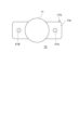
- the mount portion 17G is a rectangular parallelepiped having a long axis longer than the diameter of the vibrator 11, a portion extends radially outward from the outer edge of the vibrator 11 in a plan view of the glass plate structure 15.
- Light emitting elements 51A and 51B as the identification portion 19 are provided on the top surface 17b of this portion.
- the light emitting element 51A shown here may be configured to light up in a rotational position where the vibrator 11 is fastened to the mount part 17G, and the light emitting element 51B may be configured to light up in a rotational position where the vibrator 11 is unfastened from the mount part 17G.
- a configuration may be adopted in which both light emitting elements 51A, 51B light up simultaneously at the rotational position where they are fastened. Visibility is further improved by lighting up the plurality of light emitting elements 51A, 51B at the same time, and for example, even if one of the light emitting elements 51A, 51B is placed behind a surrounding member, the fastened state can be confirmed by the light emitted from the other light emitting element.
- the above-described light emitting elements 51, 51A, and 51B may be provided with a stop timer that stops emitting light after a predetermined period of time has passed after completion of fastening.
- the fastening state can be checked only during the assembly work of the vibrator 11, and power consumption after the assembly is completed can be suppressed.
- the light may be turned on to indicate the engaged state only when a specific signal is input from the outside. In that case, the fastened state can be checked by inputting a specific signal during maintenance.
- FIG. 17A and 17B are plan views showing the configuration and operation of a glass diaphragm 300 with a vibrator according to a fifth configuration example.
- FIG. 17A is a diagram showing a rotational position in which the vibrator 11 is unfastened to the mount part 17H
- FIG. 17B is a diagram showing a rotational position in which the vibrator 11 is fastened to the mount part 17H.
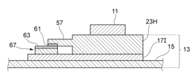
- FIG. 18 is a cross-sectional view taken along line XVIII-XVIII in FIG. 17B.
- the glass diaphragm 300 with a vibrator of this configuration includes a glass plate structure 15, a vibrator 11, a mount portion 17H, a connecting portion 23H, and an identification portion 19.
- the mount portion 17H is fixed to one main surface 15a of the glass plate structure 15 by an adhesive layer 21.
- the vibrator 11 is fixed to the connecting portion 23H.
- the connecting portion 23H has a protrusion 57 that protrudes in one direction (radially outward) from the outer edge of the vibrator 11 when the glass plate structure 15 is viewed from above.
- a terminal portion 61 that is electrically connected to a conductive wire 59 that drives the vibrator 11 is provided on the surface (lower surface) of the protrusion 57 on the mount portion 17H side shown in FIG.
- the mount portion 17H also includes a conductive terminal 63 on a portion of the top surface 17b.
- a cable 65 for transmitting a drive signal to the vibrator 11 is electrically connected to the conductive terminal 63 .
- the conductive terminal 63 is electrically connected to the terminal portion 61 formed on the projection portion 57 at the rotational position where the mount portion 17H and the connecting portion 23H are fastened together as shown in FIG. Transmission is now possible.
- the cable 65 may have a configuration in which a harness is attached to the end of a flat cable, and may be connected to the conductive terminal 63 side with a connector.
- the conductive terminal 63 and the terminal part 61 are mutually connected when the projection part 57 slides on the conductive terminal 63 of the mount part 17H and reaches the rotational position shown in FIG. electrically connected.
- the conductive terminal 63 and the terminal portion 61 may have a configuration in which a plurality of terminals are arranged along the rotation direction of each other, and the plurality of terminals are individually energized. Examples of the case where a plurality of terminals are provided include, when the identification section 19 is the above-mentioned light emitting element 51, a case where a terminal connected to a conductive wire connected to the light emitting element 51 is provided.
- the light emitting element 51 lights up and the vibrator 11 can be driven.
- the space for arranging the terminal portion 61 can be expanded, and the degree of freedom in arranging the terminal portion 61 and the conductive terminal 63 can be improved.
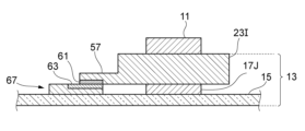
- FIGS. 19A and 19B are schematic cross-sectional views showing the arrangement relationship among the mount section, the connection section, and the conductive terminal.
- a connector terminal 67 having a conductive terminal 63 may be provided in a part of the mount portion 17I, and the terminal portion 61 provided on the projection portion 57 and the conductive terminal 63 may be electrically connected.
- the connector terminal 67 may be provided at a position away from the mount portion 17J of the glass plate structure 15. In that case, the terminal portion 61 of the connecting portion 23I is arranged at a height corresponding to the conductive terminal 63.
- the part connected to the connecting part 23I and the part having the conductive terminal 63 are separated, and the conductive terminal 63 and the mount part 17J are configured separately, improving the degree of freedom in designing each. can.
- the connecting portions 23H and 23I are rotated relative to the mount portions 17I and 17J to electrically connect the conductive terminal 63 and the terminal portion 61.
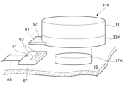
- FIG. 20A and 20B are schematic perspective views showing the configuration and operation of a vibrator-equipped glass diaphragm 310 in Modification 1 of the fifth configuration example.
- the connector terminal 67 is arranged on the glass plate structure 15 separately from the mount portion 17K, similarly to the case shown in FIG. 19B.
- a conductive terminal 63 connected to the cable 65 and a light emitting element 51 are arranged in the connector terminal 67 .
- the light emitting element 51 is wired so as to light up when conduction occurs between each terminal of the conductive terminals 63.
- an example of two conductive terminals 63 is shown, but the number of terminals is arbitrary.
- the connecting portion 23K is provided with a protruding portion 57, and a terminal portion 61 electrically connected to the above-mentioned conductive wire that drives the vibrator 11 is arranged on the surface of the protruding portion 57 facing the connector terminal 67. be done.
- the connecting portion 23K of this configuration is fastened to the mount portion 17K by pushing the glass plate structure 15 in the thickness direction, as shown in FIG. 20B.
- the fastening structure between the connecting portion 23K and the mount portion 17K is not particularly limited.
- a configuration in which a convex portion provided on one side of the connecting portion 23K and the mount portion 17K and a concave portion provided on the other are locked by an interference fit or a claw
- a configuration in which the convex portion and the concave portion are fitted together and locked by a clamp mechanism, etc.
- well-known fastening mechanisms can be used.
- the connecting portion 23K and the mount portion 17K are fastened, the protruding portion 57 is pressed against the connector terminal 67, and the conductive terminal 63 and the terminal portion 61 are electrically connected. As a result, the light emitting element 51 lights up, indicating that the connecting portion 23K and the mount portion 17K are connected. Further, although not shown, a conductive wire that drives the vibrator 11 is also electrically connected to the conductive terminal 63, so that a drive signal can be transmitted to the vibrator 11.
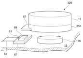
- FIGS. 21A and 21B are schematic perspective views showing the configuration and operation of a glass diaphragm 320 with a vibrator in Modification 2 of the fifth configuration example.
- a push-type switch 69 is provided on the connector terminal 67 in place of the conductive terminal 63 and terminal portion 61 of Modification 1 shown in FIGS. 20A and 20B, and when the push-type switch 69 is pressed, the light emitting element 51 is activated.
- the configuration is the same as that of Modification Example 1 except that the configuration is turned on.
- the conductive wire that drives the vibrator 11 is also electrically connected by the push switch 69, making it possible to send a drive signal to the vibrator 11.
- the light emitting element 51 lights up when the connecting portion 23K and the mount portion 17K are connected by the pushing operation, so that the connected state of both can be easily confirmed. Furthermore, the push-type switch 69 can stably switch between lighting and turning off the light emitting element 51. Note that the push switch 69 may be a switch of another type. In addition to electrical switches, a mechanical switch having a mechanism for mechanically changing the display content such as the color, characters, marks, etc. of the display section by an external force may be used.
- the glass plate structure 15 is a vehicle window, such as a side glass that opens and closes by lifting and lowering motion, or a roof glazing that opens and closes by horizontal movement, at least one side of the glass plate structure has an opening/closing drive.
- a glass holder is provided for holding a glass plate. This glass holder may be used as the aforementioned connector terminal.
- FIG. 22 is a schematic plan view showing the configuration of a vibrator-equipped glass diaphragm 330 in Modification 3 of the fifth configuration example.
- a configuration example in which a glass diaphragm with a vibrator 330 is applied to a vehicle glass plate 71 will be described.
- the vehicle glass plate 71 is raised and lowered along a window frame (not shown) by a lifting device disposed inside the door body of the vehicle.
- a belt line molding is provided on the lower edge of the window frame on the door body side. The belt line molding is in close contact with the vehicle glass plate 71, and when the vehicle glass plate 71 is raised to close the window frame, the belt line molding forms a linear seal between the vehicle glass plate 71 and the vehicle glass plate 71. form part. This sealed portion becomes the belt line BL.
- the belt line BL is shown by a broken line.
- a glass holder 73 for holding the vehicle glass plate 71 is provided on the outer peripheral edge of the vehicle glass plate 71 below the belt line BL.
- the vibrator 11, the mount section, and the connection section are arranged near one end of the glass holder 73. That is, the vibrator 11, the mount section, and the connection section are arranged in a region below the belt line BL of the vehicle glass plate 71.
- FIG. 23 is an enlarged plan view of the portion where the vibrator 11 is arranged in FIG. 22.
- FIG. 24 is a side view seen from direction P2 in FIG. 23.
- the mount portion 17L is fixed at a position away from one end 73a (FIG. 24) of the glass holder 73 of the vehicle glass plate 71.
- a connecting portion 23L to which the vibrator 11 is integrally attached is fastened to the mount portion 17L.
- the mount portion 17L and the connecting portion 23L may be fastened together by rotating the connecting portion 23L or by pushing the vehicle glass plate 71 in the thickness direction.
- the connecting portion 23L has a protrusion 57, and the protrusion 57 is provided to extend toward the glass holder 73.
- a conductive terminal 63 is provided on the surface of the glass holder 73 on the protrusion 57 side, and a terminal portion 61 is provided on the surface of the protrusion 57 on the glass holder 73 side.
- an identification portion is provided that indicates the fastening state or fastening position between the connecting portion 23L and the mount portion 17L.
- the identification portion may be provided on any of the vehicle glass plate 71, the glass holder 73, the mount portion 17L, the connection portion 23L, and the vibrator 11.
- the connecting portion 23L When the connecting portion 23L is fastened to the mount portion 17L, the conductive terminal 63 and the terminal portion 61 are electrically connected, and the vibrator 11 is in a driveable state. Moreover, when the identification part is a light emitting element, the light emitting element can be turned on to indicate that the connecting part 23L and the mount part 17L are in a fastened state.
- FIG. 25 is a cross-sectional view showing the configuration of a glass diaphragm 400 with a vibrator according to a sixth configuration example.
- a through hole 75 is formed in the glass plate structure 15 of this configuration, and the mount portion 17M is attached to pass through the through hole 75.
- the mount portion 17M includes a shaft portion 77 and a pair of flange portions 79a and 79b extending radially outward from the outer periphery of the shaft portion 77 at both ends of the shaft portion.
- the shaft portion 77 and the pair of flange portions 79a, 79b are integrally molded from a resin material, and although not shown, one of the pair of flange portions 79a, 79b is integrally formed with the shaft portion 77. It may also be a two-part structure in which the other is formed separately.
- the mount part 17M is an integrally molded resin product
- one flange part 79b is narrowed and inserted into the through hole 75.
- the flange portion 79a expanded after insertion and the other flange portion 79b are fixed to the main surfaces 15a, 15b of the glass plate structure 15 by the adhesive layer 81.
- the mount part 17M has a two-part configuration, after inserting the shaft part 77 into the through hole 75, a separately formed flange part is joined to the shaft part 77, and the pair of flange parts A configuration in which the plate structure 15 is sandwiched may also be used.
- the mount portion 17M since the mount portion 17M is fixed through the glass plate structure 15, it is prevented from coming off even under strong impact caused by, for example, opening and closing a vehicle door. Further, when an external force is applied in the direction of the glass plate structure 15, an anchor effect can be obtained, and the bonded state can be maintained more firmly. Furthermore, the vibrations from the vibrator 11 can be equally transmitted to both main surfaces 15a, 15b of the glass plate structure 15 by the pair of flange portions 79a, 79b.
- FIG. 26 is a cross-sectional view showing the structure of a glass diaphragm 410 with a vibrator according to a seventh structure example.
- the mount portion 17N of this configuration includes a sandwiching portion 17c having a pair of protruding pieces 85a and 85b facing each other in a side view of the glass plate structure 15, and a portion facing the end surface 15c of the glass plate structure 15. It has a continuous structure including.
- the inner surface of the protruding piece 85a is fixed to a part of the first main surface 15a of the glass plate structure 15, and the inner surface of the protruding piece 85b is fixed to a part of the second main surface 15b of the glass plate structure 15. be done.
- An end surface 15c of the glass plate structure 15 faces a bottom surface 17d between the pair of protruding pieces 85a and 85b.
- the mount portion 17N has at least one of the thickness from the first main surface 15a of the glass plate structure 15 and the thickness from the second main surface 15b of the glass plate structure 15, that is, the thickness of the glass plate structure 15 from the second main surface 15b. At least one of the thickness of the protruding piece 85a from the first main surface 15a and the thickness of the protruding piece 85b from the second main surface 15b of the glass plate structure 15 is preferably 30 mm or less, more preferably 25 mm or less. , 20 mm or less is more preferable. This allows for a thin configuration, reduces problems such as contact with external members, and facilitates space saving of the vibrator-equipped glass diaphragm 410.
- An adhesive layer 82 is provided at least in a portion between it and 15c. The adhesive layer 82 fixes the glass plate structure 15 in a state where it is sandwiched between the sandwiching portions 17c of the mount portion 17N.
- the mount portion 17N is provided with a connecting portion 23N for attaching the vibrator 11 that vibrates the glass plate structure 15.
- the connecting portion 23N shown here is preferably formed at a position overlapping with at least a portion of the mount portion 17N facing the first principal surface 15a, in a plan view of the first principal surface 15a of the glass plate structure 15; It is more preferable to form it at a position that overlaps with the . In that case, vibrations from the vibrator 11 can be transmitted to the glass plate structure 15 with high efficiency.
- the mount portion 17N is formed into a U-shape when the glass plate structure 15 is viewed from the side. Therefore, even if an impact is applied to the vibrator 11 or the like in the thickness direction of the glass plate structure 15, the tensile stress generated in the adhesive layer 82 is relaxed, making it difficult for the glass plate structure 15 and the mount portion 17N to separate.
- FIG. 27 is a sectional view showing a modification of the vibrator-equipped glass diaphragm 410 shown in FIG. 26.
- the vibrator 11 is biased to a position where it protrudes from the mount portion 17O when viewed from above on the first main surface 15a of the glass plate structure 15. That is, the vibrator 11 is disposed in at least a part of the area of the mount part 17O that faces and overlaps the first principal surface 15a, and a part of the vibrator 11 protrudes from the area of the mount part 17O. It is placed in a position that does not overlap with 17O.
- the connecting portion 23O can be disposed at a thick portion on the base end side (bottom surface 17d side) of the pair of protruding pieces 85a, 85b in the mount portion 17O, and The strength of the connection with the connecting portion 23O can be further increased.
- FIG. 28 is a cross-sectional view showing the configuration of a glass diaphragm 430 with a vibrator as a modification of the eighth configuration example.
- the glass plate structure 15 of this configuration is a laminated glass having a plurality of (two in this example) glass plates 15A, 15B and an intermediate layer 83 disposed between the glass plates 15A, 15B.
- a through hole 75 is formed in one of the glass plates 15A and 15B.
- the mount portion 17P has a shaft portion 77 and a flange portion 79a, and the shaft portion 77 is inserted into the through hole 75.
- the vibrator 11 is connected to the mount section 17P via the connection section 23P.
- the tip of the shaft portion 77 of the mount portion 17P can be fixed by the adhesive provided by the intermediate layer 83. Furthermore, an adhesive may be provided between the flange portion 79a and the glass plate 15B to fix the mount portion 17P and the glass plate 15B.
- the aforementioned anchor effect can be obtained in the same way.
- the through hole 75 is provided only in one glass plate 15B of the laminated glass to fix the mount part 17P, waterproofness is achieved between one side and the other side in the thickness direction of the glass plate structure 15. , stain resistance can be ensured.
- the glass plate structure 15 may be a single plate or a laminated glass.
- the structure can be simplified and the vibration characteristics can be easily controlled.
- the glass plate structure 15 is a laminated glass, it can exhibit functions depending on the structure of the intermediate layer and the like.
- the glass plate structure 15 shown in FIG. 28 is constructed by laminating a pair of glass plates 15A and 15B and including an intermediate layer 83 between these glass plates 15A and 15B.
- the shape of the plate surface of the glass plate structure 15 is arbitrary, and may be a square, a rectangle, a parallelogram, a trapezoid, another polygon, a circle, an ellipse, or any of these shapes in plan view depending on the area to which it is applied. It may also be a combination of shapes.
- the total thickness of the glass plate structure 15 is preferably 1 mm or more, more preferably 2 mm or more, and even more preferably 3 mm or more. As a result, sufficient strength can be obtained even when applied to a vehicle.
- the rigidity of the glass plate structure 15 is low, springiness due to bending of the glass due to vibration is added, and the lowest resonance frequency f 0 may become high. Therefore, when the glass plate structure 15 has a total thickness of 5 mm or less, which causes a large amount of glass deflection due to vibration, a part or the entire outer periphery of the glass plate structure 15 is fixed to a fixing member to improve the rigidity. Good.
- the intermediate layer 83 prevents the resonance of the glass plates 15A, 15B, or attenuates the vibration of the resonance of the glass plates 15A, 15B. Due to the presence of the intermediate layer 83, the glass plate structure 15 has a higher loss factor than a single plate.
- the glass plate structure 15 is preferable because the larger the loss coefficient, the greater the vibration damping.
- the loss coefficient of the glass plate structure 15 at 25°C is preferably 1 ⁇ 10 ⁇ 4 or more, and more preferably 1 ⁇ 10 ⁇ 3 or more. It is preferably 5 ⁇ 10 ⁇ 3 or more, and more preferably 5 ⁇ 10 ⁇ 3 or more.
- the loss coefficient can be measured by a dynamic elastic modulus test method such as the resonance method, and one calculated by the half-width method can be used.
- f is the resonant frequency of the material
- W is the frequency width of the point at which the amplitude h is -3 dB lower than the peak value, that is, the maximum amplitude -3 [dB]
- the value expressed as ⁇ W/f ⁇ is defined as the loss coefficient.
- the loss coefficient can be increased.
- a large loss coefficient means that the frequency width W becomes large relative to the amplitude h, making the peak broad. In other words, when the loss coefficient is large, the vibration damping ability becomes large.
- the loss coefficient is a value specific to the material and the like, and in the case of a single glass plate, for example, it differs depending on its composition, relative density, etc.
- the longitudinal wave sound velocity value in the thickness direction of the glass plate structure 15 is preferably 2.0 ⁇ 10 3 m/s or more, since the higher the sound velocity is, the better the reproducibility of high frequency sound range is when used as a diaphragm.
- the speed is more preferably .0 ⁇ 10 3 m/s or more, and even more preferably 5.0 ⁇ 10 3 m/s or more.
- the longitudinal sound velocity value is preferably 9.0 ⁇ 10 3 m/s or less.
- the longitudinal wave sound velocity value refers to the speed at which longitudinal waves propagate in the diaphragm.
- the longitudinal sound velocity value and the Young's modulus described below can be measured by the ultrasonic pulse method described in the Japanese Industrial Standards (JIS R 1602-1995).
- the glass plate structure 15 When the straight-line transmittance of the glass plate structure 15 is high, it can be used as a member having translucency. Therefore, the glass plate structure 15 preferably has a visible light transmittance of 60% or more, more preferably 65% or more, and even more preferably 70% or more, as determined in accordance with the Japanese Industrial Standards (JIS R 3106-1998). preferable.
- the refractive index of the glass plates 15A, 15B constituting the glass plate structure 15 and the intermediate layer 83 be closer to each other, since reflection and interference at the interface can be prevented.
- the difference between the refractive index of the intermediate layer 83 and the refractive index of the pair of glass plates 15A and 15B in contact with the intermediate layer 83 is preferably 0.2 or less, more preferably 0.1 or less, and even more preferably 0.01 or less. preferable.
- the glass plates 15A and 15B here may be organic glass in addition to inorganic glass.
- organic glass general transparent resins such as PMMA resin, PC resin, PS resin, PET resin, PVC resin, cellulose resin, etc. can be used.
- the resin material a resin material that can be molded into a flat plate shape or a curved plate shape is preferable.
- a resin material composited with a high hardness filler, carbon fiber, Kevlar fiber, etc. are preferable.
- the intermediate layer 83 between the plurality of glass plates stacked on each other is preferably a fluid layer made of a fluid such as liquid or liquid crystal, a gel-like material, or a solid film.
- a fluid layer made of a fluid such as liquid or liquid crystal, a gel-like material, or a solid film.
- an annular body or an adhesive may be provided around the through hole 75 (FIG. 28) to prevent the intermediate layer 83 from leaking.
- the glass plate structure 15 can realize a high loss coefficient by providing a fluid layer containing liquid as the intermediate layer 83 between at least a pair of glass plates 15A and 15B.
- the loss coefficient can be further increased by controlling the viscosity and surface tension of the fluid layer within suitable ranges. This is because, unlike the case where the pair of glass plates 15A, 15B are provided via an adhesive layer, the pair of glass plates 15A, 15B do not stick together and continue to have the vibration characteristics as each glass plate. considered to be a thing.
- fluid refers to fluids that include liquids, such as liquids, semi-solids, mixtures of solid powder and liquid, and solid gels (jelly-like substances) impregnated with liquids. It has a meaning that includes everything.
- the fluid layer preferably has a viscosity coefficient of 1 ⁇ 10 ⁇ 4 to 1 ⁇ 10 3 Pa ⁇ s at 25° C., and a surface tension of 15 to 80 mN/m at 25° C. If the viscosity is too low, it will be difficult to transmit vibrations, and if the viscosity is too high, the pair of glass plates located on both sides of the fluid layer will stick to each other and behave as a single glass plate, which will dampen resonance vibrations. It becomes difficult. Furthermore, if the surface tension of the fluid layer is too low, the adhesion between the glass plates will decrease, making it difficult to transmit vibrations. If the surface tension is too high, the pair of glass plates 15A, 15B located on both sides of the fluid layer tend to stick together, and exhibit vibrational behavior as a single glass plate 15A, 15B, so that resonance vibration is damped. It becomes difficult.
- the viscosity coefficient of the fluid layer at 25° C. is more preferably 1 ⁇ 10 ⁇ 3 Pa ⁇ s or more, and even more preferably 1 ⁇ 10 ⁇ 2 Pa ⁇ s or more. Further, the viscosity coefficient of the fluid layer at 25° C. is more preferably 1 ⁇ 10 2 Pa ⁇ s or less, and even more preferably 1 ⁇ 10 Pa ⁇ s or less.
- the surface tension of the fluid layer at 25° C. is more preferably 20 mN/m or more, and even more preferably 30 mN/m or more.
- the viscosity coefficient of the fluid layer can be measured using a rotational viscometer or the like.
- the surface tension of a fluid layer can be measured by a ring method or the like.
- the vapor pressure of the fluid layer at 25° C. and 1 atm is preferably 1 ⁇ 10 4 Pa or less, more preferably 5 ⁇ 10 3 Pa or less, and even more preferably 1 ⁇ 10 3 Pa or less.
- a seal or the like may be provided to prevent the fluid layer from evaporating. In that case, it is necessary to prevent the sealing material from interfering with the vibration of the glass diaphragm.
- components of the fluid layer include water, oil, organic solvents, liquid polymers, ionic liquids, and mixtures thereof. More specifically, propylene glycol, dipropylene glycol, tripropylene glycol, straight silicone oil (dimethyl silicone oil, methylphenyl silicone oil, methyl hydrogen silicone oil), modified silicone oil, acrylic acid polymer, liquid polybutadiene, glycerin. Examples include paste, fluorine solvent, fluororesin, acetone, ethanol, xylene, toluene, water, mineral oil, and mixtures thereof.
- a slurry in which powder is dispersed can also be used as a fluid layer.
- the fluid layer is a uniform fluid, but the above slurry is effective when imparting design or functionality such as coloring or fluorescence to the glass diaphragm.
- the powder content in the fluid layer is preferably 0 to 10% by volume, more preferably 0 to 5% by volume.
- the particle size of the powder is preferably 10 nm to 1 ⁇ m, more preferably 0.5 ⁇ m or less, from the viewpoint of preventing sedimentation.
- a fluorescent material may be included in the fluid layer.
- it may be a slurry-like fluid layer in which the fluorescent material is dispersed as a powder, or a uniform fluid layer in which the fluorescent material is mixed in the form of a liquid.
- optical functions such as light absorption and light emission can be imparted to the glass diaphragm.
- a preferable material is a substance that satisfies any of the following characteristics (1) to (3).
- the thickness of the intermediate layer 83 is 1 mm or less.
- Compression storage modulus at a temperature of 25° C. is 1.0 ⁇ 10 4 Pa or less.
- the compression storage modulus is higher than the compression loss modulus.
- the fluidity of the intermediate layer 83 is suppressed and the loss coefficient is improved.
- characteristics (1), (2), and (3) there is a trade-off relationship in which the sound velocity value of the glass plate structure 15 decreases as the intermediate layer 83 becomes thicker.
- characteristic (2) when the intermediate layer 83 is thin, the loss coefficient becomes higher in the glass plate structure 15, and a higher sound velocity value is achieved. Can be secured.
- the thickness of the intermediate layer 83 is preferably 1 mm or less, more preferably 100 ⁇ m or less, even more preferably 10 ⁇ m or less, particularly preferably 5 ⁇ m or less, from the viewpoint of obtaining a high loss coefficient of the glass plate structure 15. . Moreover, from the viewpoint of the surface roughness of the glass plates 15A and 15B, the thickness is preferably 1 ⁇ m or more.
- the material of the intermediate layer 83 preferably has a compression storage modulus of 1.0 ⁇ 10 4 Pa or less, more preferably 7.0 ⁇ 10 3 Pa or less, and 5.0 ⁇ 10 Pa or less at a temperature of 25° C. 3 Pa or less is more preferable. If the material satisfies characteristic (2), the thinner the intermediate layer 83 is, the higher the loss coefficient can be obtained in the glass plate structure 15. Further, from the viewpoint of fluidity, the pressure is preferably 1.0 ⁇ 10 2 Pa or more.
- Examples of the substance constituting the intermediate layer 83 include carbon-based, fluorine-based, or silicone-based polymer materials, provided that any of the above properties (1) to (3) are satisfied.
- a composite material that is a combination of the above materials may be used. The above materials may be used alone or in combination of two or more.
- the proportion of the substance satisfying the above specific properties in the intermediate layer 83 is preferably 10% by mass to 100% by mass, more preferably 30% by mass to 100% by mass, even more preferably 50% by mass to 100% by mass, and 70% by mass. % to 100% by weight is particularly preferred.
- materials for the intermediate layer 83 include polyvinyl butyral (PVB), ethylene vinyl acetate copolymer resin (EVA), polyurethane, polyethylene terephthalate, and polycarbonate, which are suitably used as an intermediate film for laminated glass. , etc.
- PVB polyvinyl butyral
- EVA ethylene vinyl acetate copolymer resin
- polyurethane polyethylene terephthalate
- polycarbonate which are suitably used as an intermediate film for laminated glass.
- film materials with dimming functions such as EC (Electrochromic) method, PDLC (Polymer Dispersed Liquid Crystal) method, GHLC (Guest-Host Liquid Crystal) method, SPD (Suspended Particle Device) method, and gas chromic method as an interlayer film. It may also be used as Further, an identification function indicating mount fastening may be displayed in conjunction with the film.
- ⁇ Glass plate> It is also possible to color at least one of the glass plates constituting the glass plate structure 15 and at least one of the intermediate layer 83. This is useful when it is desired to give the glass plate structure 15 a design, when adding functionality such as IR cut, UV cut, privacy glass, etc.
- the difference in mass between the glass plate 15A and the glass plate 15B is small, and it is more preferable that there is no difference in mass.
- the resonance of the lighter glass plate can be suppressed by the heavier glass plate, but it is difficult to suppress the resonance of the heavier glass plate by the lighter glass plate. That is, if there is a bias in the mass ratio, the resonance vibrations cannot be canceled out from each other in principle due to the difference in inertial force.
- the mass ratio of the glass plate 15A and the glass plate 15B expressed as (glass plate 15A/glass plate 15B) is preferably 0.8 to 1.25 (8/10 to 10/8), and 0.9 to 1.1. (9/10 to 10/9) is more preferable, and 1.0 (10/10, mass difference 0) is even more preferable.
- the thickness of the glass plates 15A and 15B is preferably 0.5 mm to 15 mm, more preferably 0.8 mm to 10 mm, and even more preferably 1.0 mm to 8 mm.
- At least one of the glass plate 15A and the glass plate 15B has a higher longitudinal sound velocity value in the thickness direction, which improves the reproducibility of the high frequency sound range, and is therefore preferable for use as a diaphragm.
- the longitudinal sound velocity value of the glass plate is preferably 4.0 ⁇ 10 3 m/s or more, more preferably 5.0 ⁇ 10 3 m/s or more, and 6.0 ⁇ 10 3 m/s. The above is more preferable.
- the upper limit is not particularly limited, but from the viewpoint of productivity of glass plates, it is preferably 7.0 ⁇ 10 3 m/s or less.
- both the glass plate 15A and the glass plate 15B satisfy the above sound velocity value. Note that the sound velocity value of the glass plate can be measured in the same manner as the longitudinal sound velocity value of the glass diaphragm.
- the number of glass plates constituting the glass plate structure 15 may be two or more, or three or more.
- each glass plate may have a different composition, all may have the same composition, or a combination of glass plates with the same composition and glass plates with different compositions may be used. good.
- a structure of two or more types of glass plates having different compositions is preferable from the viewpoint of vibration damping properties.
- the mass and thickness of the glass plates may be all different, all the same, or partially different. Among these, it is preferable from the viewpoint of vibration damping properties that all the constituent glass plates have the same mass.
- At least one of the glass plates constituting the glass plate structure 15 can be a physically strengthened glass plate or a chemically strengthened glass plate. This is useful to prevent glass plate construction 15 from breaking.
- the glass plate located at the outermost surface of the glass plate structure 15 be a physically strengthened glass plate or a chemically strengthened glass plate, and all of the glass plates constituting the glass plate are preferably made of a physically strengthened glass plate or a chemically strengthened glass plate. More preferably, it is a physically strengthened glass plate or a chemically strengthened glass plate.
- the glass plate located at the outermost surface of the glass plate structure 15 is preferably made of crystallized glass or phase splitting glass.
- one glass plate when using two or more glass plates, one glass plate can be made of the above-mentioned inorganic glass or organic glass, and the other glass plate can be replaced by a resin plate made of a resin other than organic glass, a metal plate such as aluminum, or a ceramic plate.
- Various materials such as ceramic plates can be used. From the viewpoint of design, processability, and weight, it is preferable to use organic glass, resin materials, composite materials, fiber materials, metal materials, etc. From the viewpoint of vibration characteristics, inorganic glass, highly rigid composite materials, and fiber materials are preferable. , the use of metal or ceramic materials is preferred.
- the resin material a resin material that can be molded into a flat plate shape or a curved plate shape is preferable.
- a resin material that can be molded into a flat plate shape or a curved plate shape is preferable.
- the composite material or fiber material a resin material composited with a high hardness filler, carbon fiber, Kevlar fiber, etc. are preferable.
- the metal material aluminum, magnesium, copper, silver, gold, iron, titanium, SUS, etc. are preferable, and other alloy materials may be used as necessary.
- the ceramic material ceramics and single crystal materials such as Al 2 O 3 , SiC, Si 3 N 4 , AlN, mullite, zirconia, yttria, and YAG are more preferable.
- the ceramic material is a material that has translucency.
- the glass plate structure 15 may have a planar shape or a curved shape.
- the glass plate structure 15 may have a curved shape that is curved (bent) depending on the installation location, for example.
- the shape may include both a planar portion and a curved portion. That is, the glass plate structure 15 may have a three-dimensional shape in which at least a portion thereof has a concave or convex curved portion. In this way, by creating a three-dimensional shape that matches the installation location, the appearance at the installation location can be improved and the design quality can be improved.
- the glass diaphragm with a vibrator described above can be applied to various purposes. When used as a vehicle-mounted speaker, it may be used for music, alarm sounds, etc.
- the glass plate structure of the glass diaphragm with a vibrator can be used not only for in-vehicle speakers, but also for vehicles with improved water repellency, snow accretion resistance, ice accretion resistance, and dirt resistance due to sonic vibration. It can also be used as a window.
- the glass diaphragm with a vibrator may be configured as a diaphragm for active noise canceling for noise reduction. In this case, noise that is particularly harsh on the ears can be selectively and effectively reduced.
- a vibration detection element it can function as a diaphragm for a microphone, a vibration sensor, etc.
- the present invention is not limited to the above-described embodiments, and those skilled in the art can combine the configurations of the embodiments with each other, and can modify and apply them based on the description in the specification and well-known techniques. These are also contemplated by the present invention and fall within the scope for which protection is sought.
- a glass plate structure a mount portion fixed to the glass plate structure and capable of attaching a vibrator that vibrates the glass plate structure; an identification part that is provided on at least one of the mount part and the glass plate structure and indicates a position or a fastened state where the vibrator is fastened to the glass plate structure via the mount part.
- Glass diaphragm According to this glass diaphragm, when the vibrator is fastened to the glass plate structure via the mount part, the operator can visually check the fastening position based on the identification part, and can also check whether it is in the fastened state. I can judge. Thereby, it can be easily confirmed whether the vibrator is securely attached to the glass plate structure. Furthermore, if the fastening state of the vibrator becomes loose, the fastening state can be easily corrected.
- connection part fixed to the vibrator is provided between the vibrator and the mount part,
- connection part can be easily fastened to the mount part by rotational movement.
- connection part can be fastened to the mount part by simply pushing the connection part in the thickness direction of the glass plate structure, and the installation workability of the connection part is improved.
- At least one of the mount part and the connection part has an elastic part that generates an elastic repulsive force between the mount part and the connection part,
- the glass diaphragm according to any one of (4) to (8), wherein the mount portion and the connection portion are fastened to each other while being urged by the elastic repulsive force. According to this glass diaphragm, the fastened state is maintained by the elastic repulsive force of the elastic portion.
- the mount section includes a conductive terminal, The conductive terminal according to any one of (4) to (9), wherein the conductive terminal is electrically connected to a conductive wire for driving the vibrator by fastening the mount part and the connection part. Glass diaphragm. According to this glass diaphragm, when the mount part and the connecting part are fastened together, the vibrator can be driven.
- the connecting portion has a protrusion that protrudes in one direction from the outer edge in a plan view of the glass plate structure,
- connection part can be attached to and detached from the mount part, so that, for example, the vibrator can be easily replaced with another vibrator without destroying the parts.
- the mount portion is fixed on the first main surface and the second main surface of the glass plate structure with an adhesive layer, and is formed in a U-shape when viewed from the side of the glass plate structure. ) to (16). According to this glass diaphragm, the mount portion can be fixed to the glass plate structure with high strength.
- the glass plate structure has a through hole, The glass diaphragm according to any one of (1) to (16), wherein the mount portion is inserted into the through hole and fixed to the glass plate structure. According to this glass diaphragm, the mount portion can be fixed with high strength by the glass plate structure.
- a glass diaphragm with a vibrator comprising the glass diaphragm according to any one of (1) to (19), and a vibrator that vibrates the glass diaphragm.
- the operator when the vibrator is fastened to the glass plate structure via the mount part, the operator can visually check the fastening position based on the identification part, and the fastened state can be easily confirmed by the operator. You can determine if there is. Thereby, it can be easily confirmed whether the vibrator is securely attached to the glass plate structure. Furthermore, if the fastening state of the vibrator becomes loose, the fastening state can be easily corrected. As a result, the work of fastening the vibrator to the glass plate structure and the maintenance work after the fastening can be facilitated.
Landscapes
- Engineering & Computer Science (AREA)
- Physics & Mathematics (AREA)
- Acoustics & Sound (AREA)
- Signal Processing (AREA)
- Multimedia (AREA)
- Piezo-Electric Or Mechanical Vibrators, Or Delay Or Filter Circuits (AREA)
Priority Applications (1)
| Application Number | Priority Date | Filing Date | Title |
|---|---|---|---|
| JP2024514221A JPWO2023195354A1 (https=) | 2022-04-04 | 2023-03-23 |
Applications Claiming Priority (2)
| Application Number | Priority Date | Filing Date | Title |
|---|---|---|---|
| JP2022062620 | 2022-04-04 | ||
| JP2022-062620 | 2022-04-04 |
Publications (1)
| Publication Number | Publication Date |
|---|---|
| WO2023195354A1 true WO2023195354A1 (ja) | 2023-10-12 |
Family
ID=88242861
Family Applications (1)
| Application Number | Title | Priority Date | Filing Date |
|---|---|---|---|
| PCT/JP2023/011664 Ceased WO2023195354A1 (ja) | 2022-04-04 | 2023-03-23 | ガラス振動板、及び振動子付きガラス振動板 |
Country Status (2)
| Country | Link |
|---|---|
| JP (1) | JPWO2023195354A1 (https=) |
| WO (1) | WO2023195354A1 (https=) |
Cited By (1)
| Publication number | Priority date | Publication date | Assignee | Title |
|---|---|---|---|---|
| WO2025249383A1 (ja) * | 2024-05-29 | 2025-12-04 | Agc株式会社 | ガラス振動板モジュール |
Citations (7)
| Publication number | Priority date | Publication date | Assignee | Title |
|---|---|---|---|---|
| JPS4847331U (https=) * | 1971-10-06 | 1973-06-21 | ||
| JPS57138495U (https=) * | 1981-02-20 | 1982-08-30 | ||
| JP2002118891A (ja) * | 2000-10-06 | 2002-04-19 | Kenwood Corp | スピーカ取付構造 |
| JP2006180368A (ja) * | 2004-12-24 | 2006-07-06 | Fujitsu Ten Ltd | 車両の内装板を振動板としたスピーカ装置 |
| JP2007251544A (ja) * | 2006-03-15 | 2007-09-27 | Fujitsu Ten Ltd | 音声発生装置 |
| JP2019068368A (ja) * | 2017-10-04 | 2019-04-25 | Agc株式会社 | ガラス振動板構成体及び開口部材 |
| WO2019172076A1 (ja) * | 2018-03-06 | 2019-09-12 | Agc株式会社 | スピーカー装置 |
-
2023
- 2023-03-23 WO PCT/JP2023/011664 patent/WO2023195354A1/ja not_active Ceased
- 2023-03-23 JP JP2024514221A patent/JPWO2023195354A1/ja active Pending
Patent Citations (7)
| Publication number | Priority date | Publication date | Assignee | Title |
|---|---|---|---|---|
| JPS4847331U (https=) * | 1971-10-06 | 1973-06-21 | ||
| JPS57138495U (https=) * | 1981-02-20 | 1982-08-30 | ||
| JP2002118891A (ja) * | 2000-10-06 | 2002-04-19 | Kenwood Corp | スピーカ取付構造 |
| JP2006180368A (ja) * | 2004-12-24 | 2006-07-06 | Fujitsu Ten Ltd | 車両の内装板を振動板としたスピーカ装置 |
| JP2007251544A (ja) * | 2006-03-15 | 2007-09-27 | Fujitsu Ten Ltd | 音声発生装置 |
| JP2019068368A (ja) * | 2017-10-04 | 2019-04-25 | Agc株式会社 | ガラス振動板構成体及び開口部材 |
| WO2019172076A1 (ja) * | 2018-03-06 | 2019-09-12 | Agc株式会社 | スピーカー装置 |
Cited By (1)
| Publication number | Priority date | Publication date | Assignee | Title |
|---|---|---|---|---|
| WO2025249383A1 (ja) * | 2024-05-29 | 2025-12-04 | Agc株式会社 | ガラス振動板モジュール |
Also Published As
| Publication number | Publication date |
|---|---|
| JPWO2023195354A1 (https=) | 2023-10-12 |
Similar Documents
| Publication | Publication Date | Title |
|---|---|---|
| US11290807B2 (en) | Speaker device | |
| US12023894B2 (en) | Glass sheet composite | |
| US11122370B2 (en) | Glass sheet composite | |
| US11856381B2 (en) | Vibration device | |
| JP5950860B2 (ja) | 空中超音波センサ | |
| WO2023195354A1 (ja) | ガラス振動板、及び振動子付きガラス振動板 | |
| WO2023243643A1 (ja) | ガラス振動板及び振動子付きガラス振動板 | |
| US11849296B2 (en) | Vibration device for generating acoustic performance | |
| WO2022045027A1 (ja) | ガラス板構成体、振動板および開口部材 | |
| US20200230922A1 (en) | Glass sheet composite | |
| WO2023063368A1 (ja) | エキサイタ付きガラス振動板、車両用振動板及び建築物用振動板 | |
| JP6950742B2 (ja) | ディスプレイ装置およびテレビジョン装置 | |
| WO2023224049A1 (ja) | ガラス振動板付車体構造 | |
| WO2023199889A1 (ja) | ガラス振動板、及び振動子付きガラス振動板 | |
| WO2023063370A1 (ja) | ガラス振動板、ガラス振動板の製造方法、エキサイタ付きガラス振動板、車両用振動板及び建築物用振動板 | |
| US6459211B1 (en) | Damping/muffling structure for electroluminescent cell | |
| CN119213790A (zh) | 玻璃振动板、带振子的玻璃振动板以及玻璃振动板的制造方法、带振子的玻璃振动板的制造方法 | |
| WO2023068311A1 (ja) | ガラス振動板、エキサイタ付きガラス振動板及び車両用窓ガラス | |
| JP4102590B2 (ja) | 発光部品 | |
| JP7816366B2 (ja) | 電子機器付車両用ガラス板 | |
| WO2023195528A1 (ja) | ガラス振動板及び振動子付きガラス振動板 | |
| WO2024057893A1 (ja) | ガラス振動板及び振動子付きガラス振動板 | |
| WO2023224082A1 (ja) | ガラス振動板及び振動子付きガラス振動板 | |
| JP3084535U (ja) | 無機電子励起発光部品 |
Legal Events
| Date | Code | Title | Description |
|---|---|---|---|
| 121 | Ep: the epo has been informed by wipo that ep was designated in this application |
Ref document number: 23784644 Country of ref document: EP Kind code of ref document: A1 |
|
| ENP | Entry into the national phase |
Ref document number: 2024514221 Country of ref document: JP Kind code of ref document: A |
|
| NENP | Non-entry into the national phase |
Ref country code: DE |
|
| 122 | Ep: pct application non-entry in european phase |
Ref document number: 23784644 Country of ref document: EP Kind code of ref document: A1 |