WO2023068311A1 - ガラス振動板、エキサイタ付きガラス振動板及び車両用窓ガラス - Google Patents
ガラス振動板、エキサイタ付きガラス振動板及び車両用窓ガラス Download PDFInfo
- Publication number
- WO2023068311A1 WO2023068311A1 PCT/JP2022/039008 JP2022039008W WO2023068311A1 WO 2023068311 A1 WO2023068311 A1 WO 2023068311A1 JP 2022039008 W JP2022039008 W JP 2022039008W WO 2023068311 A1 WO2023068311 A1 WO 2023068311A1
- Authority
- WO
- WIPO (PCT)
- Prior art keywords
- glass
- glass plate
- diaphragm
- exciter
- threaded portion
- Prior art date
Links
Images


Classifications
-
- B—PERFORMING OPERATIONS; TRANSPORTING
- B32—LAYERED PRODUCTS
- B32B—LAYERED PRODUCTS, i.e. PRODUCTS BUILT-UP OF STRATA OF FLAT OR NON-FLAT, e.g. CELLULAR OR HONEYCOMB, FORM
- B32B17/00—Layered products essentially comprising sheet glass, or glass, slag, or like fibres
-
- B—PERFORMING OPERATIONS; TRANSPORTING
- B60—VEHICLES IN GENERAL
- B60J—WINDOWS, WINDSCREENS, NON-FIXED ROOFS, DOORS, OR SIMILAR DEVICES FOR VEHICLES; REMOVABLE EXTERNAL PROTECTIVE COVERINGS SPECIALLY ADAPTED FOR VEHICLES
- B60J1/00—Windows; Windscreens; Accessories therefor
-
- C—CHEMISTRY; METALLURGY
- C03—GLASS; MINERAL OR SLAG WOOL
- C03C—CHEMICAL COMPOSITION OF GLASSES, GLAZES OR VITREOUS ENAMELS; SURFACE TREATMENT OF GLASS; SURFACE TREATMENT OF FIBRES OR FILAMENTS MADE FROM GLASS, MINERALS OR SLAGS; JOINING GLASS TO GLASS OR OTHER MATERIALS
- C03C27/00—Joining pieces of glass to pieces of other inorganic material; Joining glass to glass other than by fusing
- C03C27/06—Joining glass to glass by processes other than fusing
-
- H—ELECTRICITY
- H04—ELECTRIC COMMUNICATION TECHNIQUE
- H04R—LOUDSPEAKERS, MICROPHONES, GRAMOPHONE PICK-UPS OR LIKE ACOUSTIC ELECTROMECHANICAL TRANSDUCERS; DEAF-AID SETS; PUBLIC ADDRESS SYSTEMS
- H04R7/00—Diaphragms for electromechanical transducers; Cones
- H04R7/02—Diaphragms for electromechanical transducers; Cones characterised by the construction
- H04R7/04—Plane diaphragms
- H04R7/06—Plane diaphragms comprising a plurality of sections or layers
- H04R7/08—Plane diaphragms comprising a plurality of sections or layers comprising superposed layers separated by air or other fluid
-
- H—ELECTRICITY
- H04—ELECTRIC COMMUNICATION TECHNIQUE
- H04R—LOUDSPEAKERS, MICROPHONES, GRAMOPHONE PICK-UPS OR LIKE ACOUSTIC ELECTROMECHANICAL TRANSDUCERS; DEAF-AID SETS; PUBLIC ADDRESS SYSTEMS
- H04R7/00—Diaphragms for electromechanical transducers; Cones
- H04R7/02—Diaphragms for electromechanical transducers; Cones characterised by the construction
- H04R7/12—Non-planar diaphragms or cones
Definitions
- the present invention relates to a vibrating glass plate, a vibrating glass plate with an exciter, and a window glass for a vehicle.
- Patent Literature 1 and Patent Literature 2 disclose a structure for transmitting the vibration of an electrically vibrating exciter (piezoelectric actuator) to a diaphragm such as a glass plate.
- an exciter is screwed so as to pass through an opening in a second plate facing the first plate with a core material interposed therebetween, and the exciter is attached to the first plate via a spacer. being contacted.
- an exciter is fixed to one end of a rod member, which is a vibration transmitting portion, and the other end of the rod member is adhered to the diaphragm via a rod holding member.
- Patent Document 2 also discloses a diaphragm structure including a plurality of substrates and an intermediate layer arranged between the substrates as a glass substrate (diaphragm structure).
- an object of the present invention is to provide a vibrating glass plate, a vibrating glass plate with an exciter, and a window glass for a vehicle, which are strongly fixed to an exciter, which is a vibrating device, and can accurately reproduce a predetermined vibration.
- the present invention consists of the following configurations.
- a glass plate a mount portion connected and fixed to the glass plate, A first threaded portion and a second threaded portion are formed in the mount portion, the first threaded portion and the second threaded portion are a combination of a right-hand thread structure and a left-hand thread structure;
- a glass diaphragm with an exciter comprising the glass diaphragm according to (1) above and an exciter fixed to the mount portion.
- a window glass for a vehicle wherein the glass diaphragm with an exciter according to (2) above is attached to a vehicle.
- the exciter which is a vibrating device, and can accurately reproduce predetermined vibrations.
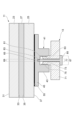
- FIG. 1 is a schematic plan view of a glass diaphragm with an exciter.
- FIG. 2 is a schematic cross-sectional view of the glass diaphragm shown in FIG. 1, taken along line II-II.
- FIG. 3 is a schematic plan view of a fixed portion of the mount section on the glass diaphragm.
- FIG. 4 is a schematic diagram of a fixed portion of the mount section on the glass diaphragm.
- FIG. 5 is a schematic cross-sectional view of a glass diaphragm with a mount section fixed to the fourth surface.
- FIG. 6A is a schematic cross-sectional view showing a configuration example with another mounting structure for the exciter.
- FIG. 6A is a schematic cross-sectional view showing a configuration example with another mounting structure for the exciter.
- FIG. 6B is a schematic cross-sectional view showing a configuration example with another mounting structure for the exciter.
- FIG. 6C is a schematic cross-sectional view showing a configuration example with another mounting structure for the exciter.
- FIG. 6D is a schematic plan view showing a configuration example with another mounting structure for the exciter.
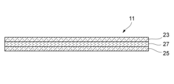
- FIG. 7 is a schematic cross-sectional view of a glass diaphragm made of laminated glass.
- FIG. 8 is a plan view of a vehicle in which the glass diaphragm with an exciter is applied to the window glass.
- FIG. 1 is a schematic plan view of a glass diaphragm 100 with an exciter.
- the exciter-equipped glass diaphragm 100 includes a glass diaphragm 11 and an exciter 13 that generates vibration. By driving the exciter 13, the glass diaphragm 11 is vibrated to generate a desired sound. .
- the exciter 13 is a vibrating device that uses an attached object as a diaphragm and generates sound from the diaphragm.
- the exciter 13 attached to the glass diaphragm 11 imparts vibration to the glass diaphragm 11 to generate sound, for example, enhancing the acoustic effect in the vehicle.
- a known exciter can be used for the exciter 13 .
- the exciter-equipped glass diaphragm 100 when the exciter-equipped glass diaphragm 100 is provided as a side window of a vehicle, the exciter 13 is arranged on the connection portion 15 side with the lifting mechanism (not shown) below the belt line BL. As a result, the sound generated from the glass diaphragm 11 can be supplied into the vehicle interior.
- the beltline BL corresponds to the lower side of the opening when the side window is fully closed when the side window is attached to the vehicle (door).
- the glass diaphragm 11 may be laminated glass made up of a plurality of glass plates, or may be single-plate glass made up of one glass plate. In this configuration example, a glass diaphragm 11 made of laminated glass will be described as an example.
- FIG. 2 is a schematic cross-sectional view of the glass diaphragm 11 shown in FIG. 1 taken along line II-II.
- FIG. 3 is a schematic plan view of a fixed portion of the mount portion 41 on the glass diaphragm 11.
- the glass diaphragm 11 is composed of laminated glass having a first glass plate 23, a second glass plate 25, and an intermediate layer 27 between the first glass plate 23 and the second glass plate 25. be done.
- the intermediate layer 27 is composed of an intermediate film such as resin, a fluid layer such as liquid or liquid crystal, or a gel layer.
- the intermediate layer 27 has a function of preventing resonance between the first glass plate 23 and the second glass plate 25 or damping vibration of resonance.
- the intermediate layer 27 may be an air layer without an intermediate film, fluid layer or gel layer.
- spacers are provided to define the thickness of the air layer at predetermined intervals, to prevent resonance between the first glass plate 23 and the second glass plate 25, or to dampen vibration of resonance. may be provided at predetermined intervals (in plan view), in which case the intermediate layer 27 may not be entirely filled with air.
- the thickness of the first glass plate 23 is preferably 0.5 mm to 15 mm, more preferably 0.8 mm to 10 mm, even more preferably 1.0 mm to 8 mm, and the thickness of the second glass plate 25 is preferably 0.5 mm to 15 mm, more preferably 0.8 mm to 10 mm, even more preferably 1.0 mm to 8 mm.
- the glass diaphragm 11 only the first glass plate 23, or both the first glass plate 23 and the second glass plate 25 may be chemically strengthened glass or physically strengthened glass. If the glass plate is tempered glass, the strength of the glass diaphragm 11 can be increased. Also, the first glass plate 23 and the second glass plate 25 may be curved glass having a curved shape. When the first glass plate 23 and the second glass plate 25 are curved glass, the appearance of the glass diaphragm 11 can be improved and the design can be enhanced.
- the first glass plate 23 and the second glass plate 25 may have, for example, a single-curved shape curved in one of the vertical and horizontal directions (with respect to one side of the frame) when mounted on a vehicle. , may have a compound curved shape curved both vertically and horizontally.
- the radius of curvature of the main surface to which the mount portion 41 is attached is preferably 3000 mm or more.
- the upper limit of the radius of curvature is not particularly limited, but is preferably 100000 mm or less, for example.
- the first glass plate 23 has a first surface 31 and a second surface 33.
- the main surface of the first glass plate 23 is the first surface 31 on the outside, and the main surface on the intermediate layer 27 side is the second surface 33 .
- the second glass plate 25 has a third surface 35 and a fourth surface 37 .
- the second glass plate 25 has a third surface 35 as a principal surface on the intermediate layer 27 side and a fourth surface 37 as an outer principal surface.
- the glass diaphragm 11 has a second glass plate 25 formed with a through hole 39 penetrating through the second glass plate 25 .
- This through hole 39 is formed in the thickness direction of the second glass plate 25 .
- the outer edge of the through-hole 39 is circular in plan view of the second glass plate 25 .
- the shape of the outer edge of the through-hole 39 is preferably circular, but may be various shapes such as an elliptical shape and a polygonal shape.
- the glass diaphragm 11 has a mount portion 41 to which the exciter 13 is attached. Thereby, the glass diaphragm 11 is vibrated by the exciter 13 attached to the mount portion 41 .
- This mount portion 41 is provided in a through hole 39 formed in the second glass plate 25 and fixed to the glass diaphragm 11 .
- the exciter 13 is fixed to the mount portion 41 and attached to the glass diaphragm 11 via the mount portion 41 .
- the mount part 41 can be made of materials such as metal materials such as aluminum or aluminum alloys, titanium alloys, magnesium alloys, and stainless steel, ceramics, glass, resin materials, carbon fibers, and composite materials made of these materials.
- the resin material include acrylic resins such as polymethyl methacrylate resin (PMMA), polycarbonate (PC), polyvinyl chloride (PVC), urethane, polypropylene (PP), ABS resin, etc., and are excellent in moldability. can be configured By using the above materials, cracks or the like do not occur in the mount portion 41, and sufficient connection strength can be obtained.
- the mount portion 41 preferably has a longitudinal wave sound velocity value of 2.0 ⁇ 10 3 m/s or more and an attenuation coefficient of 1.0 ⁇ 10 ⁇ 3 or more. If the longitudinal wave sound velocity value and the damping coefficient are set to the above numerical values, the reproducibility of the high frequency range can be improved, and the resonance vibration can be damped. Furthermore, it is more preferable that the mount portion 41 has the same longitudinal wave sound velocity value as at least one of the first glass plate 23 and the second glass plate 25 , and It is even more preferred to have longitudinal sound velocity values.
- the mount part 41 has a columnar part 43.
- the mount portion 41 has an extension portion 45 extending through the through hole 39 and extending around the through hole 39 in plan view of the second glass plate 25 .
- the projecting portion 45 is sandwiched between the first glass plate 23 and the second glass plate 25 .
- the projecting portion 45 faces the third surface 35 of the second glass plate 25 as a peripheral portion 47 at a portion located outside the through hole 39 .
- the mount portion 41 is connected to the second surface 33 of the first glass plate 23 and the third surface 35 of the second glass plate 25 via adhesive layers 51 and 53 .
- the mount portion 41 has a bottom surface facing the second surface 33 of the first glass plate 23 adhered by an adhesive layer 51 and a peripheral portion 47 facing the third surface 35 of the second glass plate 25 adhered by an adhesive layer 53 .
- the glass diaphragm 11 does not necessarily have the adhesive layers 51 and 53.
- the overhanging portion 45 is physically fixed between the first glass plate 23 and the second glass plate 25, so that the mount can be mounted.
- Part 41 may be fixed.
- the mount portion 41 itself may be made of a material having adhesive properties. In this case, the mount portion 41 is considered to include the adhesive layers 51 and 53. 53 may not be provided.
- adhesives such as thermosetting adhesives, light-curing adhesives, and moisture-curing adhesives can be used.
- thermosetting adhesives by devising the types and proportions of materials put in the adhesive, the crosslink density can be increased, and heat resistance, chemical resistance, and moisture resistance after curing can be improved.
- photocurable adhesive the work time can be shortened because the adhesive can be instantaneously adhered by irradiating ultraviolet rays.
- the adhesive layers 51 and 53 may be polyvinyl butyral resin (PVB).
- the thickness of the adhesive layers 51 and 53 is preferably 5 ⁇ m to 100 ⁇ m. When the thicknesses of the adhesive layers 51 and 53 are within the above range, the mount portion 41 can be fixed to the glass diaphragm 11 with a necessary and sufficient bonding strength.
- FIG. 4 is a schematic diagram of a fixed portion of the mount portion 41 on the glass diaphragm 11.
- the mount portion 41 has the area of S1 in the plan view of the second glass plate 25 .
- :S2 is preferably in the range of 1:1.2 to 1:100. With this area ratio, the mount portion 41 can be adhered and fixed to the first glass plate 23 and the second glass plate 25 satisfactorily.
- the peripheral portion 47 has a circular outer edge in plan view of the second glass plate 25 . That is, the peripheral portion 47 has an annular shape with a circular inner edge, and is rotationally symmetrical with respect to the central axis O of the mount portion 41 . Thereby, the mount portion 41 is adhesively fixed to the first glass plate 23 and the second glass plate 25 in a well-balanced manner.
- the shape of the peripheral portion 47 of the mount portion 41 in plan view of the second glass plate 25 is not limited to an annular shape as long as it is rotationally symmetrical about the central axis O of the mount portion 41 .
- the peripheral portion 47 of the mount portion 41 may have a polygonal shape such as a triangle or a square, or an elliptical shape, or may have a structure in which a plurality of radially extending portions are rotationally symmetrically arranged. If the peripheral portion 47 of the mount portion 41 has a shape extending radially from the outer edge shape, the mount portion 41 and the glass plate can be easily bonded to each other when the glass plate has a curved surface shape.
- the mount part 41 may be accommodated inside the through hole 39 of the second glass plate 25 in a state of being fixed to the glass diaphragm 11 .
- the mount portion 41 does not have a portion that protrudes outward from the fourth surface 37 of the second glass plate 25, the mount portion 41 does not interfere with the manufacturing and transportation of the glass diaphragm 11. , damage to the mount portion 41 can be easily avoided.
- the mount portion 41 provided inside the through hole 39 of the second glass plate 25 is attached to the second surface 33 of the first glass plate 23 via the adhesive layer 51 . , and further connected to the third surface 35 of the second glass plate 25 via the adhesive layer 53 . Therefore, when the exciter 13 as a vibrating device is attached to the mount portion 41 , both the first glass plate 23 and the second glass plate 25 constituting the glass vibrating plate 11 can be vibrated effectively by the exciter 13 .
- the mounting portion 41 is attached by bonding without providing the through hole 39 in the fourth surface 37 of the second glass plate 25, or the through hole of the second glass plate 25 is attached.
- the mount portion 41 is attached only to the second surface 33 of the first glass plate 23 through 39, the phase difference between the vibrations of the first glass plate 23 and the second glass plate 25 can be suppressed. Therefore, the sound reproduction capability of the glass diaphragm 11 can be improved, and the glass diaphragm 11 including the first glass plate 23 and the second glass plate 25 can function as a high-performance diaphragm.
- the phase difference between the first surface 31 and the fourth surface 37 is within 0.5 rad with respect to the frequency of 1 kHz at the position of the center of gravity.
- the phase difference is preferably within 0.3 rad, more preferably within 0.1 rad, and still more preferably within 0.05 rad.
- a through hole is formed through both the first glass plate 23 and the second glass plate 25, and a rod-shaped mount portion is passed through the through hole.
- Adhesive fixing to the first surface 31 and the fourth surface 37 is also conceivable.
- the mounting portion is complicated, and there is a problem that the mounting portion protrudes outward from the first surface 31 and the fourth surface 37 .
- the through hole 39 is formed only in the second glass plate 25, and the mount portion 41 is accommodated inside the through hole 39. Therefore, there is no complication of the mount portion 41, no portions protruding outward from the first surface 31 and the fourth surface 37 of the mount portion 41, and ingress of water at fixed portions of the mount portion 41 can be suppressed.
- the mount portion 41 is formed with a first screw portion 63 and a second screw portion 65 .
- the first threaded portion 63 and the second threaded portion 65 are a combination of a right-hand thread structure and a left-hand thread (reverse thread) structure.
- a right-hand thread structure is a thread structure that is tightened by turning it to the right (clockwise)
- a left-hand thread structure is a screw structure that is tightened by turning it to the left (counterclockwise).
- the first screw portion 63 has a right-hand thread structure
- the second screw portion 65 has a left-hand thread structure.
- the second screw portion 65 has a right-hand thread structure.
- the mount portion 41 has a circular concave portion 67 in plan view of the second glass plate 25 .
- the concave portion 67 is opened at the end surface of the columnar portion 43 .
- the outer surface of the recessed portion 67 is formed with a threaded structure that is a female thread, thereby forming the first threaded portion 63 having a first threaded diameter.
- the mount portion 41 has a circular concave portion 69 in plan view of the second glass plate 25 .
- This recessed portion 69 is a recessed portion having a diameter smaller than that of the recessed portion 67 and is formed in the bottom portion of the recessed portion 67 .
- the outer surface of the recessed portion 69 is formed with a threaded structure consisting of a female thread, thereby forming a second threaded portion 65 having a second threaded diameter.
- the concave portions 67 and 69 are each formed in a circular shape around the central axis O of the mount portion 41 . Therefore, the center of the first thread diameter of the first threaded portion 63 coincides with the center of the second threaded diameter of the second threaded portion 65 .
- the first thread diameter of the first threaded portion 63 and the second threaded diameter of the second threaded portion 65 are different from each other. Specifically, the first thread diameter of the first threaded portion 63 formed on the outer surface of the recess 67 is the second thread diameter of the second threaded portion 65 formed on the outer surface of the recess 69 having a diameter smaller than that of the recess 67. bigger than In addition, the outer edge of the first threaded portion 63 is outside the outer edge of the second threaded portion 65 in plan view of the second glass plate 25 .
- the exciter 13 attached to the mount portion 41 has an exciter body 71 and a convex portion 73 projecting from the exciter body 71 .
- a threaded portion 75 serving as a male screw is formed on the outer surface of the convex portion 73 .
- the convex portion 73 formed with the threaded portion 75 is screwed into and fastened to the first threaded portion 63 of the mount portion 41 .
- the exciter 13 is formed with an insertion hole 77 at its center, and a fastening bolt 81 is inserted into the insertion hole 77 .
- the fastening bolt 81 has a threaded portion 83 made of a male thread, and has a large-diameter head portion 85 at its rear end.
- the fastening bolt 81 is inserted into the insertion hole 77 of the exciter 13 from the tip side and screwed into the second screw portion 65 of the mount portion 41 .
- the exciter 13 fixed to the mount portion 41 is further firmly fixed by pressing the head portion 85 of the fastening bolt 81 against the rear surface of the exciter main body 71 .
- the exciter is attached to the mount portion 41 by using the first screw portion 63 formed on the outer surface of the recess 67 and the second screw portion 65 formed on the outer surface of the recess 69 . 13 is fixed. Therefore, the exciter 13 can be easily attached to and detached from the mount portion 41, and can be easily replaced. Further, the exciter 13 can be firmly fixed to the mount portion 41 by the first screw portion 63 and the second screw portion 65, and the glass diaphragm 11 can be vibrated effectively. This allows the glass diaphragm 11 to function as a high-performance diaphragm.
- first threaded portion 63 and the second threaded portion 65 are a combination of a right-hand thread structure and a left-hand thread structure, loosening can be suppressed, and the exciter 13 can be maintained in a good state of being fixed to the mount portion 41 .
- the exciter 13 is fixed by a second screw portion 65 different from the fastening portion of the first screw portion 63, and the back side of the exciter main body 71 is pressed by the head portion 85 of the fastening bolt 81, whereby the glass diaphragm is 11 lowest resonance frequencies can be adjusted.
- the screw diameters of the first threaded portion 63 and the second threaded portion 65 are different, and the outer edge of the first threaded portion 63 is wider than the outer edge of the second threaded portion 65 in a plan view of the second glass plate 25 . placed outside. Therefore, the exciter 13 can be firmly fixed to the mount portion 41 without loosening, and the fastening force of the first screw portion 63 and the fastening force of the second screw portion 65 can be applied in a well-balanced manner.
- the mount portion 41 can be mounted at the same center position.
- the exciter 13 can be fixed firmly and with good balance.
- the mount portion 41 is accommodated in the through hole 39 of the second glass plate 25 and fixed to the first glass plate 23 and the second glass plate 25 by bonding.
- the fixing of the mount portion 41 to the is not limited to the above configuration example.
- FIG. 5 is a schematic cross-sectional view of the glass diaphragm 11 in which the mount portion 41 is fixed to the fourth surface 37 of the second glass plate 25.
- the mount portion 41 may be adhesively fixed to the fourth surface 37 , which is the main surface of the second glass plate 25 , with an adhesive layer 55 .
- the mount portion 41 may be adhesively fixed to the main surface of the glass diaphragm 11 made of a single plate glass.
- the adhesive layer 55 preferably uses the same material as the adhesive layers 51 and 53 and has the same thickness as the adhesive layers 51 and 53 .
- the mount portion 41 itself may use a material having adhesiveness. In this case, the mount portion 41 is considered to include the adhesive layer 55, so the adhesive layer 55 is not provided as a member different from the mount portion 41. may
- the mounting structure of the exciter 13 to the mount portion 41 is not limited to the above configuration example, and may be another structure.
- a configuration example having another mounting structure for the exciter 13 will be described below.
- the same reference numerals are assigned to the same members or parts as those described above, and the description thereof will be omitted or simplified.
- FIG. 6A is a schematic cross-sectional view showing a configuration example with another mounting structure for the exciter 13.
- a screw structure is formed on the convex side surface of the columnar portion 43 protruding from the fourth surface 37 of the second glass plate 25 in the mount portion 41 to form the first screw portion 63 .
- the second threaded portion 65 is formed on the end surface of the columnar portion 43 of the mount portion 41 .
- the exciter body 71 of the exciter 13 attached to the mount portion 41 is formed with a screw portion 79 serving as a female screw on the mounting side of the mount portion 41 .
- the exciter 13 is fastened to the mount portion 41 by screwing the first screw portion 63 of the mount portion 41 into the screw portion 79 . Further, the exciter 13 is fastened to the mount portion 41 by screwing the screw portion 83 of the fastening bolt 81 inserted into the insertion hole 77 into the second screw portion 65 of the mount portion 41 . As a result, the exciter 13 is firmly fixed to the mount portion 41 without loosening by using the first threaded portion 63 and the second threaded portion 65 which have a reverse thread structure.
- FIG. 6B is a schematic cross-sectional view showing a configuration example with another mounting structure for the exciter 13.
- the columnar portion 43 of the mount portion 41 is formed in the shape of a round bar, and the columnar portion 43 protrudes from the fourth surface 37 of the second glass plate 25 .
- a screw structure is formed on the convex side surface of the columnar portion 43 of the mount portion 41 to form a first screw portion 63 and a second screw portion 65 .
- the first threaded portion 63 and the second threaded portion 65 are provided at the same position with the same diameter when the second glass plate 25 is viewed from above.
- both the right-hand thread structure and the left-hand thread structure are formed on the convex side surface of the columnar portion 43 of the mount portion 41, so that the first thread portion 63 and the second thread portion 65 are provided. ing. That is, the first threaded portion 63 and the second threaded portion 65 having a reverse thread structure are formed on the outer peripheral surface of the same axis.
- the exciter 13 attached to the mount part 41 has a threaded part 79 made of a female thread penetrating through the front and back of the exciter body 71 .
- the exciter 13 is fastened to the mount portion 41 by screwing the first screw portion 63 of the columnar portion 43 of the mount portion 41 into the screw portion 79 thereof. Further, the exciter 13 is screwed by screwing the second threaded portion 65 of the columnar portion 43 of the mount portion 41 into a fastening nut 89 having a threaded portion 79 of the exciter 13 and a threaded portion 87 formed of a reverse threaded female thread. It is fastened to the mount portion 41 .
- the exciter 13 is firmly fixed to the mount portion 41 without loosening by using the first threaded portion 63 and the second threaded portion 65 which have a reverse thread structure.
- the first threaded portion 63 and the second threaded portion 65 are a combination of a right-handed thread structure and a left-handed threaded structure formed on the convex side surface at the same position with the same diameter. The structure can be simplified compared to the case where the 63 and the second threaded portion 65 are formed at different positions.
- a first threaded portion 63 and a second threaded portion 65 having a combination of a right-handed thread structure and a left-handed threaded structure are formed on the concave side surface of the mount portion 41 at the same position with the same diameter, and a male thread is formed on the outer periphery.
- the exciter 13 may be fastened and fixed to the mount portion 41 by screwing the exciter 13 and the externally and reversely threaded bolts of the exciter 13 .
- FIGS. 6C and 6D are diagrams showing a configuration example having another mounting structure for the exciter 13, where FIG. 6C is a schematic cross-sectional view and FIG. 6D is a schematic plan view.
- the first threaded portion 63 is formed at a position where the center of the first threaded diameter coincides with the center of the mount portion 41 in plan view of the second glass plate 25 .
- the second threaded portion 65 is formed at a position outside the outer edge of the first threaded portion 63 .
- a plurality of second screw portions 65 (four in this example) are arranged rotationally symmetrically on the circumference around the first screw portion 63 in a plan view of the second glass plate 25 .
- a structure in which the mounting portion 41 is adhered and fixed to the fourth surface 37 that is the main surface of the second glass plate 25 by the adhesive layer 55 is illustrated.
- the exciter 13 attached to the mount portion 41 has a plurality of (in this example, four) through-holes 77 rotationally symmetrical on the circumference centered on the screw portion 75 in the exciter body 71 .
- the screw portion 75 of the exciter 13 is screwed into the first screw portion 63 of the mount portion 41 to be fastened.
- fastening bolts 81 are inserted into the plurality of insertion holes 77 of the exciter 13 , and the threaded portions 83 of these fastening bolts 81 are screwed into the plurality of second threaded portions 65 of the mount portion 41 .
- the exciter 13 fastened to the mount portion 41 is further firmly fixed by pressing the heads 85 of the plurality of fastening bolts 81 against the back surface of the exciter main body 71 .
- the exciter 13 is fixed at the center of the mount portion 41 by the first screw portion 63 , and furthermore, the first screw portion 63 and the first screw portion 63 are mounted at rotationally symmetrical positions around the fixed location of the first screw portion 63 .
- the exciter 13 is fixed to the mount portion 41 by a plurality of reverse threaded second screw portions 65 . As a result, the exciter 13 can be firmly and well-balanced fixed to the mount portion 41 .
- the glass diaphragm 11 may be a laminated glass in which a plurality of the glass plates 23 and 25 described above are laminated and an intermediate layer 27 is provided between the glass plates 23 and 25, or may be a single glass plate. . In the case of a single plate, the configuration can be simplified and the vibration characteristics can be easily controlled.
- FIG. 7 is a schematic cross-sectional view of a glass diaphragm 11 made of laminated glass.
- the glass diaphragm 11 is formed by laminating a first glass plate 23 and a second glass plate 25 (hereinafter also referred to as a pair of glass plates 23 and 25), and including an intermediate layer 27 between the glass plates 23 and 25. Configured.
- the shape of the plate surface of the glass diaphragm 11 is arbitrary, and may be square, rectangular, parallelogram, trapezoidal, other polygonal, circular, elliptical, or a combination of these shapes depending on the application site. good.
- the total thickness of the glass diaphragm 11 is preferably 2 mm or more, more preferably 3 mm or more, and even more preferably 4 mm or more. As a result, necessary and sufficient strength can be obtained even when applied to vehicles and buildings.
- the intermediate layer 27 prevents the glass plates 23 and 25 from resonating or attenuates the vibration of the resonance of the glass plates 23 and 25 . Due to the presence of the intermediate layer 27, the glass diaphragm 11 has a higher loss factor than the glass plate alone.
- the glass diaphragm 11 preferably has a larger loss factor because the vibration attenuation increases, and the loss factor of the glass diaphragm 11 at 25° C. is preferably 1 ⁇ 10 ⁇ 3 or more, more preferably 2 ⁇ 10 ⁇ 3 or more. , 5 ⁇ 10 ⁇ 3 or more is more preferable.
- the loss factor can be measured, for example, by a dynamic elastic modulus test method such as the resonance method, and the one calculated by the half-value width method is used.
- W is the frequency width at a point -3 dB lower than the peak value of the resonance frequency f and amplitude h of the material, that is, the point at the maximum amplitude -3 [dB].
- Define loss factor. Resonance can be suppressed by increasing the loss factor.
- a large loss factor means that the frequency width W is relatively large with respect to the amplitude h, and the peak is broadened. In other words, the greater the loss factor, the greater the vibration damping capacity.
- the loss factor is a value specific to the material, etc. For example, in the case of a
- the longitudinal wave sound velocity value in the plate thickness direction of the glass diaphragm 11 is preferably 4.0 ⁇ 10 3 m / s or more because the reproducibility of high-frequency sound is improved when the sound velocity is increased, and 4 It is more preferably 0.5 ⁇ 10 3 m/s or more, and even more preferably 5.0 ⁇ 10 3 m/s or more.
- the longitudinal wave sound velocity value is preferably 7.0 ⁇ 10 3 m/s or less.
- the longitudinal wave sound velocity value refers to the velocity at which the longitudinal wave propagates in the diaphragm.
- a longitudinal wave sound velocity value and a Young's modulus, which will be described later, can be measured by an ultrasonic pulse method described in Japanese Industrial Standards (JIS R 1602-1995).
- the glass diaphragm 11 has a high in-line transmittance, it can be applied as a translucent member. Therefore, the glass diaphragm 11 preferably has a visible light transmittance of 60% or more, more preferably 65% or more, and even more preferably 70% or more, as determined in accordance with Japanese Industrial Standards (JIS R 3106-1998).
- Examples of the translucent member include transparent speakers, transparent microphones, construction, opening members for vehicles, and the like.
- the difference between the refractive index of the intermediate layer 27 and the refractive index of the pair of glass plates 23 and 25 in contact with the intermediate layer 27 is preferably 0.2 or less, more preferably 0.1 or less, and even more preferably 0.01 or less.
- the glass plates 23 and 25 here may be inorganic glass or organic glass.
- organic glass PMMA-based resin, PC-based resin, PS-based resin, PET-based resin, PVC-based resin, cellulose-based resin, etc. can be used as general transparent resins.
- the resin material it is preferable to use a resin material that can be molded into a flat plate shape or a curved plate shape.
- a resin material compounded with a high-hardness filler, carbon fiber, Kevlar fiber, or the like is preferable.
- intermediate layer 27 between the plurality of laminated glass plates it is preferable to use a fluid layer such as a liquid or a liquid crystal, a gel-like material, or a solid film.
- a fluid layer such as a liquid or a liquid crystal, a gel-like material, or a solid film.
- the glass diaphragm 11 can achieve a high loss factor by providing a fluid layer containing liquid as the intermediate layer 27 between at least the pair of glass plates 23 and 25 . Above all, by setting the viscosity and surface tension of the fluid layer within a suitable range, the loss factor can be further increased. It is considered that this is because, unlike the case where the pair of glass plates are provided via an adhesive layer, the pair of glass plates do not adhere to each other and each glass plate maintains its vibration characteristics.
- the term "fluid” as used herein refers to liquids, semi-solids, mixtures of solid powders and liquids, solid gels (jelly-like substances) impregnated with liquids, etc. It means to include all things.
- the fluid layer preferably has a viscosity coefficient of 1 ⁇ 10 ⁇ 4 to 1 ⁇ 10 3 Pa ⁇ s at 25° C. and a surface tension of 15 to 80 mN/m at 25° C. If the viscosity is too low, it becomes difficult to transmit vibrations, and if the viscosity is too high, the pair of glass plates positioned on both sides of the fluid layer will adhere to each other and exhibit vibration behavior as a single glass plate, thus damping the resonance vibration. become difficult. On the other hand, if the surface tension is too low, the adhesion between the glass plates will decrease, making it difficult to transmit vibrations. If the surface tension is too high, the pair of glass plates positioned on both sides of the fluid layer are likely to adhere to each other, exhibiting vibration behavior as a single glass plate, making it difficult to attenuate resonance vibration.
- the fluid layer preferably has a viscosity coefficient of 1 ⁇ 10 ⁇ 4 to 1 ⁇ 10 3 Pa ⁇ s at 25° C. and a surface tension of 15 to 80 mN/m at 25° C. If the viscosity is too low, it becomes difficult to transmit vibrations, and if the viscosity is too high, the pair of glass plates positioned on both sides of the fluid layer will adhere to each other and exhibit vibration behavior as a single glass plate, thus damping the resonance vibration. become difficult. Also, if the surface tension of the fluid layer is too low, the adhesion between the glass plates will be reduced, making it difficult to transmit vibrations. If the surface tension is too high, the pair of glass plates positioned on both sides of the fluid layer are likely to adhere to each other, exhibiting vibration behavior as a single glass plate, making it difficult to attenuate resonance vibration.
- the viscosity coefficient of the fluid layer at 25° C. is more preferably 1 ⁇ 10 ⁇ 3 Pa ⁇ s or more, and even more preferably 1 ⁇ 10 ⁇ 2 Pa ⁇ s or more. Further, the viscosity coefficient of the fluid layer at 25° C. is more preferably 1 ⁇ 10 2 Pa ⁇ s or less, and even more preferably 1 ⁇ 10 Pa ⁇ s or less.
- the surface tension of the fluid layer at 25° C. is more preferably 20 mN/m or more, still more preferably 30 mN/m or more.
- the viscosity coefficient of the fluid layer can be measured using a rotational viscometer.
- the surface tension of the fluid layer can be measured by a ring method or the like.
- the fluid layer preferably has a vapor pressure of 1 ⁇ 10 4 Pa or less at 25° C. and 1 atm, more preferably 5 ⁇ 10 3 Pa or less, even more preferably 1 ⁇ 10 3 Pa or less.
- a seal or the like may be applied so that the fluid layer does not evaporate. In that case, it is necessary that the sealing material does not interfere with the vibration of the glass diaphragm.
- the thickness of the fluid layer may be 1/10 or less of the total thickness of the pair of glass plates.
- the following is preferable, 1/30 or less is more preferable, 1/50 or less is still more preferable, 1/70 or less is particularly preferable, and 1/100 or less is most preferable.
- the thickness of the fluid layer may be 100 ⁇ m or less, preferably 50 ⁇ m or less, more preferably 30 ⁇ m or less, even more preferably 20 ⁇ m or less, and 15 ⁇ m.
- the following are particularly preferable, and 10 ⁇ m or less is most preferable.
- the lower limit of the thickness of the fluid layer is preferably 0.01 ⁇ m or more from the viewpoint of film formability and durability.
- the fluid layer is chemically stable, and it is preferable that the fluid layer and the pair of glass plates located on both sides of the fluid layer do not react.
- Chemically stable means, for example, a material that is less altered (deteriorated) by light irradiation, or a material that does not solidify, vaporize, decompose, discolor, or chemically react with glass in a temperature range of at least -20 to 70°C. do.
- components of the fluid layer include water, oil, organic solvents, liquid polymers, ionic liquids and mixtures thereof. More specifically, propylene glycol, dipropylene glycol, tripropylene glycol, straight silicone oil (dimethyl silicone oil, methylphenyl silicone oil, methyl hydrogen silicone oil), modified silicone oil, acrylic acid polymer, liquid polybutadiene, glycerin Paste, fluorinated solvent, fluorinated resin, acetone, ethanol, xylene, toluene, water, mineral oil, mixtures thereof, and the like.
- it preferably contains at least one selected from the group consisting of propylene glycol, dimethylsilicone oil, methylphenylsilicone oil, methylhydrogensilicone oil and modified silicone oil, and more preferably contains propylene glycol or silicone oil as the main component.
- slurry in which powder is dispersed can also be used as a fluid layer.
- a uniform fluid is preferable for the fluid layer, but the slurry is effective when imparting design and functionality such as coloring and fluorescence to the glass diaphragm.
- the powder content in the fluid layer is preferably 0 to 10% by volume, more preferably 0 to 5% by volume.
- the particle size of the powder is preferably 10 nm to 1 ⁇ m, more preferably 0.5 ⁇ m or less.
- the fluid layer may contain a fluorescent material.
- a fluorescent material in this case, it may be a slurry-like fluid layer in which the fluorescent material is dispersed as powder, or a uniform fluid layer in which the fluorescent material is mixed as a liquid. This makes it possible to impart optical functions such as light absorption and light emission to the glass diaphragm.
- the intermediate layer 27 is a fluid layer containing a liquid and the first glass plate 23 is provided with the through holes 39 (see FIG. 2), the liquid in the intermediate layer 27 is sealed so as not to leak from the through holes 39.
- a structure is preferably provided.
- This encapsulation structure can be formed, for example, by a process similar to the liquid crystal polymer encapsulation process in liquid crystal displays. Specifically, a resin material (cured resin) that serves as a sealing material is applied in advance to the portion to be processed of the through hole 39 of the first glass plate 23 . Then, through holes 39 are formed in the laminated glass obtained by laminating the first glass plate 23 and the second glass plate 25 by using a laminated glass hole processing process.
- the through holes 39 are formed in the first glass plate 23 in advance, and the first glass plate 23 and the second glass plate 25 are overlapped.
- a ring-shaped sealing material is provided at a position corresponding to the through hole 39 of the second glass plate 25 according to the shape of the through hole 39 .
- the sealing material is sandwiched between the first glass plate 23 and the second glass plate 25, so that the fluid layer between the first glass plate 23 and the second glass plate 25 leaks through the through holes 39. to prevent
- a preferable material is a substance that satisfies any one of the following properties (1) to (3).
- the thickness of the intermediate layer 27 is 1 mm or less; (2) a compression storage modulus at a temperature of 25° C. of 1.0 ⁇ 10 4 Pa or less; (3) At a temperature of 25° C. and 1 Hz, the compression storage modulus is higher than the compression loss modulus.
- the fluidity of the intermediate layer 27 is suppressed and the loss factor is improved.
- the loss factor of the glass diaphragm is improved by increasing the thickness of the intermediate layer 27, there is a trade-off relationship in which the sound velocity value of the glass diaphragm 11 decreases as the intermediate layer 27 becomes thicker.
- the material of the intermediate layer 27 satisfies the characteristic (2), so that when the intermediate layer 27 is thin, the glass diaphragm 11 has a higher loss factor and secures a high sound velocity value. can.
- the thickness of the intermediate layer 27 is preferably 1 mm or less, more preferably 100 ⁇ m or less, even more preferably 10 ⁇ m or less, and particularly preferably 5 ⁇ m or less, from the viewpoint of obtaining a high loss factor of the glass diaphragm 11 . From the viewpoint of the surface roughness of the glass plates 23 and 25, it is preferably 1 ⁇ m or more.
- the material of the intermediate layer 27 preferably has a compression storage elastic modulus of 1.0 ⁇ 10 4 Pa or less at a temperature of 25° C., more preferably 7.0 ⁇ 10 3 Pa or less, and more preferably 5.0 ⁇ 10 3 Pa or less is more preferable. If the material satisfies the characteristic (2), the thinner the thickness of the intermediate layer 27, the higher the loss factor in the glass diaphragm 11 can be obtained. Moreover, from the viewpoint of fluidity, 1.0 ⁇ 10 2 Pa or more is preferable.
- a gel-like material can also be used as the material of the intermediate layer 27 .
- Materials constituting the intermediate layer 27 include, for example, carbon-based, fluorine-based, or silicone-based polymeric materials on the premise that any one of the above characteristics (1) to (3) is satisfied. .
- a composite material obtained by combining the above materials may be used. The above materials may be used alone or in combination of two or more.
- the ratio of the substance satisfying the above specific properties in the intermediate layer 27 is preferably 10% by mass to 100% by mass, more preferably 30% by mass to 100% by mass, even more preferably 50% by mass to 100% by mass, and 70% by mass. % to 100% by weight is particularly preferred.
- the material of the intermediate layer 27 includes polyvinyl butyral resin (PVB), ethylene-vinyl acetate copolymer resin (EVA), polyurethane resin, and silicone, which are suitably used as intermediate films for laminated glass. resin, polyethylene terephthalate resin, polycarbonate resin, and the like.
- ⁇ Glass plate> It is also possible to color at least one of the glass plates constituting the glass diaphragm 11 and at least one of the intermediate layer 27 . This is useful, for example, when the glass diaphragm 11 is desired to have a design, or when functions such as IR cut, UV cut, and privacy glass are added.
- the values of the peak tops of the resonance frequencies of one glass plate and the other glass plate are different, and it is more preferable that the resonance frequency ranges do not overlap.
- the resonance frequency ranges of the glass plate 23 and the glass plate 25 overlap or the peak top values are the same, one of the glass plates will resonate due to the existence of the intermediate layer 27.
- the vibration of the other glass plate is not synchronized. As a result, resonance is canceled to some extent, and a higher loss factor can be obtained than in the case of using only the glass plate.
- the resonance frequency (peak top) of one glass plate 23 is Qa
- the half width of the resonance amplitude is wa
- the resonance frequency (peak top) of the other glass plate 25 is Qb
- the half width of the resonance amplitude is wb, , preferably satisfies the following formula (1). (wa+wb)/4 ⁇
- ) between the resonance frequencies of the glass plates 23 and 25 increases, resulting in a high loss factor.
- the difference in mass between the glass plate 23 and the glass plate 25 is as small as possible, and it is more preferable that there is no difference in mass.
- the resonance of the lighter glass plate can be suppressed by the heavier glass plate, but it is difficult to suppress the resonance of the heavier glass plate by the lighter glass plate. That is, if the mass ratio is biased, the resonance vibrations cannot be canceled out in principle due to the difference in inertial force.
- the mass ratio of the glass plate 23 and the glass plate 25 represented by (glass plate 23/glass plate 25) is preferably 0.8 to 1.25 (8/10 to 10/8), more preferably 0.9 to 1.1. (9/10 to 10/9) is more preferred, and 1.0 (10/10, mass difference 0) is even more preferred.
- the thickness of the glass plates 23 and 25 is as thin as possible for use as a diaphragm.
- the thickness of each of the glass plates 23 and 25 may be 15 mm or less, preferably 10 mm or less, more preferably 5 mm or less, even more preferably 3 mm or less, and particularly preferably 1.5 mm or less.
- the glass plate is too thin, the effect of surface defects in the glass plate is significant, cracking is likely to occur, and strengthening treatment is difficult.
- each of the glass plates 23 and 25 is preferably 0.5 mm to 15 mm, more preferably 0.8 mm to 10 mm, and even more preferably 1.0 mm to 8 mm.
- the loss factor of the glass plate at 25° C. is preferably 1 ⁇ 10 ⁇ 4 or more, more preferably 3 ⁇ 10 ⁇ 4 or more, and even more preferably 5 ⁇ 10 ⁇ 4 or more.
- the upper limit is not particularly limited, it is preferably 5 ⁇ 10 ⁇ 3 or less from the viewpoint of productivity.
- both the glass plate 23 and the glass plate 25 have the above loss factor.
- the loss factor of the glass plate can be measured by the same method as the loss factor of the glass diaphragm 11 .
- At least one of the glass plate 23 and the glass plate 25 has a higher longitudinal wave sound velocity value in the plate thickness direction, which improves the reproducibility of the high-frequency sound range, and is therefore preferable as a diaphragm.
- the longitudinal wave sound velocity value of the glass plate is preferably 4.0 ⁇ 10 3 m/s or more, more preferably 5.0 ⁇ 10 3 m/s or more, and 6.0 ⁇ 10 3 m/s. The above is more preferable.
- the upper limit is not particularly limited, it is preferably 7.0 ⁇ 10 3 m/s or less from the viewpoint of productivity of the glass plate.
- both the glass plate 23 and the glass plate 25 satisfy the above sound velocity values.
- the sound velocity value of the glass plate can be measured by the same method as the longitudinal wave sound velocity value of the glass diaphragm.
- compositions of the glass plate 23 and the glass plate 25 are not particularly limited, the following ranges are preferable, for example.
- SiO 2 40 to 80% by mass, Al 2 O 3: 0 to 35% by mass, B 2 O 3 : 0 to 15% by mass, MgO: 0 to 20% by mass, CaO: 0 to 20% by mass, SrO: 0 to 20% by mass, BaO: 0 to 20% by mass, Li 2 O: 0 to 20% by mass, Na 2 O: 0 to 25% by mass, K 2 O: 0 to 20% by mass, TiO 2 : 0 to 10% by mass , and ZrO 2 : 0 to 10% by mass.
- the above composition accounts for 95% by mass or more of the entire glass.
- the compositions of the glass plate 23 and the glass plate 25 expressed in mol % based on the oxide are within the following range. SiO 2 : 55 to 75% by mass, Al 2 O 3 : 0 to 25% by mass, B 2 O 3 : 0 to 12% by mass, MgO: 0 to 20% by mass, CaO: 0 to 20% by mass, SrO: 0 ⁇ 20% by mass, BaO: 0 to 20% by mass, Li 2 O: 0 to 20% by mass, Na 2 O: 0 to 25% by mass, K 2 O: 0 to 15% by mass, TiO 2 : 0 to 5% by mass %, and ZrO 2 : 0 to 5% by mass.
- the above composition accounts for 95% by mass or more of the entire glass.
- the specific gravity of each of the glass plates 23 and 25 is the less energy the glass plates can be vibrated.
- the specific gravity of each of the glass plates 23 and 25 is preferably 2.8 or less, more preferably 2.6 or less, and even more preferably 2.5 or less.
- the lower limit is not particularly limited, it is preferably 2.2 or more.
- the specific elastic moduli of the glass plates 23 and 25 are preferably 2.5 ⁇ 10 7 m 2 /s 2 or more, more preferably 2.8 ⁇ 10 7 m 2 /s 2 or more, and 3.0 ⁇ 10 7 m 2 /s 2 or more is more preferable.
- the upper limit is not particularly limited, it is preferably 4.0 ⁇ 10 7 m 2 /s 2 or less.
- the glass plates may be used as the glass plates constituting the glass diaphragm 11 .
- the glass plates may all have different compositions, may all have the same composition, or may have the same composition and different compositions. may be used in combination with Among them, it is preferable to use two or more kinds of glass plates having different compositions from the viewpoint of vibration damping.
- the mass and thickness of the glass plates may be different, all the same, or partially different. Above all, it is preferable from the standpoint of vibration damping that all the constituent glass plates have the same mass.
- the rigidity of the glass plate structure can be improved by fixing a part or the entire circumference of the glass plate structure to the member on the stationary side.
- a physically strengthened glass plate or a chemically strengthened glass plate can also be used for at least one of the glass plates constituting the glass plate structure. This is useful to prevent breakage of the glass sheet construction.
- the glass plate positioned on the outermost surface of the glass plate structure be a physically strengthened glass plate or a chemically strengthened glass plate, and all of the glass plates constituting the glass plate structure are physically strengthened.
- a glass plate or a chemically strengthened glass plate is more preferred.
- crystallized glass or phase-separated glass is also useful in terms of increasing the longitudinal wave sound velocity value and strength.
- the glass plate structure may be flat or curved.
- the glass plate structure may, for example, have a curved surface that curves (bends) according to the installation location. Also, although not shown, it may have a shape that includes both a planar portion and a curved portion. That is, the glass plate structure may have a three-dimensional shape having at least a portion thereof curved in a concave or convex shape. In this way, by forming a three-dimensional shape in accordance with the installation location, the appearance at the installation location can be improved, and the design can be enhanced.
- the exciter 13 is connected to one main surface of the various glass plate structures described above via a mount portion 41.
- the exciter 13 may be connected to the region of the single plate through the mount portion 41 . That is, of the pair of glass plates 23 and 25 of the glass plate structure, the outer edge of one glass plate extends further outside than the other glass plate. Also, a suitable sealing material is provided at the end of one of the glass plates and the intermediate layer to seal the intermediate layer. Then, the exciter 13 is attached via the mount portion 41 to the portion (region of the single plate) extending to the outside of one of the glass plates.
- the glass diaphragm with an exciter described above can be applied to various uses.
- the glass diaphragm of the glass diaphragm with an exciter may be a vehicle window glass.
- FIG. 8 is a plan view of a vehicle in which the glass diaphragm with an exciter is applied to the window glass.
- the vehicle window glass composed of the glass diaphragm may be the front side window FSW of the vehicle 91, but is not limited to this.
- the rear side window RSW, windshield WS, rear window RW, roof glazing RG, front quarter window FQW, etc. of the vehicle 91 may be used.
- the vehicle glazing may be a wind deflector used in convertibles.
- the glass diaphragm may be glass for the interior of the vehicle.
- interior glass include those provided in various interior materials such as dashboards, center consoles, ceilings, door trims, pillar lining panels, and sun visors.
- Glass diaphragms can also be used as vehicle windows, building windows, structural members, and decorative panels with improved water repellency, anti-snow, anti-icing, and antifouling properties due to sonic vibration.
- the glass diaphragm with the exciter may be a vehicle-mounted or machine-mounted speaker.
- the glass diaphragm with an exciter is used, for example, as a member for electronic equipment, such as a full-range speaker, a speaker for bass reproduction in the 15 Hz to 200 Hz band, a large speaker with a diaphragm area of 0.2 m 2 or more, a flat speaker, a cylindrical speaker, and a transparent speaker.
- cover glass for mobile devices that function as speakers, cover glass for TV displays, video screens, displays where video and audio signals are generated from the same surface, speakers for wearable displays, electronic displays, lighting fixtures, etc. can.
- the speaker may be for music, alarm sound, or the like.
- the glass diaphragm with an exciter may be configured as an active noise control diaphragm for noise reduction.
- a vibration detection element it can function as a diaphragm for a microphone, a vibration sensor, or the like.
- the present invention is not limited to the above-described embodiments, and those skilled in the art can make modifications and applications by combining each configuration of the embodiments with each other, based on the description of the specification and well-known techniques. It is also contemplated by the present invention that it falls within the scope of protection sought.
- this specification discloses the following matters. (1) a glass plate; a mount portion connected and fixed to the glass plate, A first threaded portion and a second threaded portion are formed in the mount portion, the first threaded portion and the second threaded portion are a combination of a right-hand thread structure and a left-hand thread structure; A glass diaphragm in which the glass plate is vibrated via the mount section. According to this glass diaphragm, a device such as an exciter can be easily attached to and detached from the mount portion by using the first threaded portion and the second threaded portion of the mount portion, and the device can be easily replaced.
- the device can be firmly fixed to the mount portion by the first screw portion and the second screw portion, and the glass diaphragm can be vibrated effectively. This allows the glass diaphragm to function as a high-performance diaphragm. Furthermore, since the first threaded portion and the second threaded portion are a combination of a right-handed threaded structure and a left-handed threaded structure, it is possible to suppress loosening at the mutual fastening points and maintain a good fixed state of the device to the mount portion. .
- the center of the first screw diameter which is the diameter of the first screw portion, coincides with the center of the mount portion
- the second screw portion is the diameter of the first screw portion.
- the glass diaphragm according to (1) or (2) located outside the outer edge. According to this glass diaphragm, the device can be fixed to the mount portion at the center of the mount portion by the first screw portion, and the device can be fixed to the mount portion outside the outer edge of the first screw portion by the second screw portion.
- the device can be firmly fixed to the mount section by using the first threaded section and the second threaded section formed on the concave side surface of the mount section.
- the first threaded portion and the second threaded portion according to any one of (1) to (6), wherein the first threaded portion and the second threaded portion are formed by a combination of a convex side thread structure and a concave side thread structure.
- glass diaphragm According to this glass diaphragm, the device can be firmly fixed to the mount section by using the first threaded section and the second threaded section, which are a combination of screw structures formed on the convex side surface and the concave side surface of the mount section. .
- the first threaded portion and the second threaded portion have the same diameter and are at the same position,
- the device is attached to the mount section by using the first threaded section and the second threaded section formed on both convex side surfaces or both concave side surfaces. Can be firmly fixed without loosening.
- first threaded portion and the second threaded portion have the same diameter and the same position on both the convex side surfaces or both the concave side surfaces, the first threaded portion and the second threaded portion have a right-handed thread structure and a left-handed thread structure.
- the structure can be simplified as compared with the case where the two screw portions are formed at separate positions.
- the glass plate is a first glass plate having a first side and a second side;
- glass diaphragm According to this glass diaphragm, the mount portion is arranged in the through hole formed in the second glass plate, the mount portion is connected to the second surface of the first glass plate, and the third surface and the third surface of the second glass plate are connected to each other. It can be connected to at least one of the four faces.
- the exciter when an exciter, which is a vibrating device, is attached to the mount portion, the exciter can effectively vibrate both the first glass plate and the second glass plate that constitute the glass diaphragm, and the first glass plate can vibrate. Also, the phase difference of the vibration applied to the second glass plate can be suppressed. This allows the glass diaphragm including the first glass plate and the second glass plate to function as a high-performance diaphragm.
- the mount section has a structure extending through the through hole and extending around the through hole in a plan view of the second glass plate, and is between the first glass plate and the second glass plate.
- a glass diaphragm with an exciter comprising the glass diaphragm according to any one of (1) to (15) and an exciter fixed to the mount section.
- the exciter can be easily attached to and detached from the mount by using the first threaded portion and the second threaded portion of the mount, and can be easily replaced.
- the glass diaphragm can be vibrated effectively, and the glass diaphragm can function as a high-performance diaphragm.
- first threaded portion and the second threaded portion are a combination of a right-handed threaded structure and a left-handed threaded structure, it is possible to suppress loosening at the mutual fastening portion, and to maintain a good fixed state of the exciter to the mount portion. .
- a window glass for a vehicle wherein the glass diaphragm with an exciter according to (16) is attached to a vehicle.
- a desired sound can be generated from the vehicle window glass by attaching the glass diaphragm with the exciter to the vehicle as the vehicle window glass.
Abstract
本発明に係るガラス振動板(11)は、第1ガラス板(23)と第2ガラス板(25)とからなるガラス板と、ガラス板と接続固定されるマウント部(41)と、を有し、マウント部(41)には、第1ネジ部(63)および第2ネジ部(65)が形成され、第1ネジ部(63)および第2ネジ部(65)は、右ねじ構造および左ねじ構造の組合せであり、マウント部(41)を介してガラス板が加振される。
Description
本発明は、ガラス振動板、エキサイタ付きガラス振動板及び車両用窓ガラスに関する。
近年、様々な板状の部材として、例えば、電子機器用部材、車両用窓部材、車両等の輸送機械の内装用部材を、振動させてスピーカとして機能させる技術が検討されている。
例えば、特許文献1及び特許文献2には、電気的に振動させるエキサイタ(圧電アクチュエータ)の振動をガラス板などの振動板に伝える構造が開示されている。
特許文献1の構成では、芯材を介在させて第1の板に向き合った第2の板の開口を貫通するようにエキサイタが捻じ込み装着され、このエキサイタがスペーサを介して第1の板に接触されている。
特許文献2の構成では、振動伝達部であるロッド部材の一端部にエキサイタが固定され、ロッド部材の他端部がロッド保持部材を介して振動板に接着されている。また、特許文献2には、ガラス基板(振動板構成体)として、複数の基板および基板間に配置される中間層を含む振動板構成体も開示されている。
特許文献1の構成では、芯材を介在させて第1の板に向き合った第2の板の開口を貫通するようにエキサイタが捻じ込み装着され、このエキサイタがスペーサを介して第1の板に接触されている。
特許文献2の構成では、振動伝達部であるロッド部材の一端部にエキサイタが固定され、ロッド部材の他端部がロッド保持部材を介して振動板に接着されている。また、特許文献2には、ガラス基板(振動板構成体)として、複数の基板および基板間に配置される中間層を含む振動板構成体も開示されている。
しかしながら、特許文献1,2に記載の技術では、いずれも、エキサイタと振動板との固定が十分ではなく、エキサイタの振動をガラス板等の振動板に的確に伝えにくいことや、使用中にエキサイタが振動板から脱落する懸念があること、といった実用上の問題があった。
そこで本発明は、加振装置であるエキサイタとの固定が強く、所定の振動を的確に再現できるガラス振動板、エキサイタ付きガラス振動板及び車両用窓ガラスの提供を目的とする。
本発明は下記構成からなる。
(1) ガラス板と、
前記ガラス板と接続固定されるマウント部と、を有し、
前記マウント部には、第1ネジ部および第2ネジ部が形成され、
前記第1ネジ部および前記第2ネジ部は、右ねじ構造および左ねじ構造の組合せであり、
前記マウント部を介して前記ガラス板が加振される、ガラス振動板。
(2) 上記(1)に記載のガラス振動板と、前記マウント部に固定されるエキサイタと、を有する、エキサイタ付きガラス振動板。
(3) 上記(2)に記載のエキサイタ付きガラス振動板が、車両に取付けられる、車両用窓ガラス。
(1) ガラス板と、
前記ガラス板と接続固定されるマウント部と、を有し、
前記マウント部には、第1ネジ部および第2ネジ部が形成され、
前記第1ネジ部および前記第2ネジ部は、右ねじ構造および左ねじ構造の組合せであり、
前記マウント部を介して前記ガラス板が加振される、ガラス振動板。
(2) 上記(1)に記載のガラス振動板と、前記マウント部に固定されるエキサイタと、を有する、エキサイタ付きガラス振動板。
(3) 上記(2)に記載のエキサイタ付きガラス振動板が、車両に取付けられる、車両用窓ガラス。
本発明によれば、加振装置であるエキサイタとの固定が強く、所定の振動を的確に再現できる。
以下、本発明の実施形態について、図面を参照して詳細に説明する。
<エキサイタ付きガラス振動板の構成>
図1は、エキサイタ付きガラス振動板100の概略平面図である。
図1に示すように、エキサイタ付きガラス振動板100は、ガラス振動板11と、振動を発生するエキサイタ13とを備え、エキサイタ13の駆動によりガラス振動板11を振動させて所望の音響を発生させる。
<エキサイタ付きガラス振動板の構成>
図1は、エキサイタ付きガラス振動板100の概略平面図である。
図1に示すように、エキサイタ付きガラス振動板100は、ガラス振動板11と、振動を発生するエキサイタ13とを備え、エキサイタ13の駆動によりガラス振動板11を振動させて所望の音響を発生させる。
エキサイタ13は、取り付けられる対象物を振動板として利用し、振動板から音を発生させる加振装置である。ガラス振動板11に装着されたエキサイタ13は、ガラス振動板11に振動を付与して音を発生させ、例えば、車内の音響効果を高める効果等を奏する。
エキサイタ13には公知のものを使用できる。
エキサイタ13には公知のものを使用できる。
例えば、エキサイタ付きガラス振動板100を車両のサイドウインドウとして設ける場合、ベルトラインBLよりも下方の昇降機構(不図示)との接続部15側に、エキサイタ13を配置する。これにより、車両室内にガラス振動板11から発生する音響が供給可能となる。なお、ベルトラインBLは、サイドウインドウを車両(ドア)に取り付けたときに、サイドウインドウが全閉となるときの開口部の下辺に相当する。詳細は後述するが、エキサイタ付きガラス振動板100の用途はこれに限らない。
ガラス振動板11は、複数枚のガラス板からなる合わせガラスでもよく、また、1枚のガラス板からなる単板ガラスでもよい。本構成例では、合わせガラスからなるガラス振動板11を例示して説明する。
図2は、図1に示すガラス振動板11のII-II線における概略断面図である。図3は、ガラス振動板11におけるマウント部41の固定箇所を平面視した概略平面図である。
図2に示すように、ガラス振動板11は、第1ガラス板23、第2ガラス板25、及び第1ガラス板23と第2ガラス板25との間の中間層27を有する合わせガラスで構成される。中間層27は、樹脂等の中間膜、液体又は液晶等の流体からなる流体層、あるいはゲル状体の層からなる。中間層27は、第1ガラス板23と第2ガラス板25の共振を防止、又は共振の揺れを減衰させる機能を有する。中間層27は、中間膜、流体層あるいはゲル状体の層などがない空気層でもよい。中間層27が空気層である場合、所定間隔で空気層の厚さを画定するため、または第1ガラス板23と第2ガラス板25の共振を防止、又は共振の揺れを減衰させるためのスペーサが(平面視の)所定間隔で設けられてもよく、その場合、中間層27全てが空気で充填されてなくてもよい。
図2に示すように、ガラス振動板11は、第1ガラス板23、第2ガラス板25、及び第1ガラス板23と第2ガラス板25との間の中間層27を有する合わせガラスで構成される。中間層27は、樹脂等の中間膜、液体又は液晶等の流体からなる流体層、あるいはゲル状体の層からなる。中間層27は、第1ガラス板23と第2ガラス板25の共振を防止、又は共振の揺れを減衰させる機能を有する。中間層27は、中間膜、流体層あるいはゲル状体の層などがない空気層でもよい。中間層27が空気層である場合、所定間隔で空気層の厚さを画定するため、または第1ガラス板23と第2ガラス板25の共振を防止、又は共振の揺れを減衰させるためのスペーサが(平面視の)所定間隔で設けられてもよく、その場合、中間層27全てが空気で充填されてなくてもよい。
ガラス振動板11において、第1ガラス板23の厚さは、0.5mm~15mmが好ましく、0.8mm~10mmがより好ましく、1.0mm~8mmがさらに好ましく、第2ガラス板25の厚さは、0.5mm~15mmが好ましく、0.8mm~10mmがより好ましく、1.0mm~8mmがさらに好ましい。
ガラス振動板11は、第1ガラス板23のみ、または第1ガラス板23及び第2ガラス板25の両方が化学強化ガラスまたは物理強化ガラスでもよい。ガラス板が強化ガラスであれば、ガラス振動板11の強度を高められる。また、第1ガラス板23及び第2ガラス板25は、曲面状を有する曲面ガラスでもよい。第1ガラス板23及び第2ガラス板25が曲面ガラスであると、ガラス振動板11の外観を良好にでき、意匠性を高められる。
また、第1ガラス板23、第2ガラス板25は、例えば、車両に装着したときの(枠の一辺に対して)垂直方向又は水平方向の一方に湾曲した単曲形状を有してもよく、垂直方向及び水平方向の両方に湾曲した複曲形状を有してもよい。ガラス振動板11が湾曲形状を有する場合、マウント部41が主面に取り付けられる主面の曲率半径は3000mm以上が好ましい。第1ガラス板23、第2ガラス板25が湾曲形状を有する場合、曲率半径の上限はとくに制限はないが、例えば、100000mm以下が好ましい。
第1ガラス板23は、第1面31と第2面33を有する。第1ガラス板23は、外側の主面が第1面31であり、中間層27側の主面が第2面33である。第2ガラス板25は、第3面35と第4面37を有する。第2ガラス板25は、中間層27側の主面が第3面35であり、外側の主面が第4面37である。
図2及び図3に示すように、ガラス振動板11は、第2ガラス板25に、第2ガラス板25を貫通する貫通孔39が形成されている。この貫通孔39は、第2ガラス板25の厚さ方向に形成されている。本例では、貫通孔39の外縁は、第2ガラス板25の平面視において円形状に形成されている。なお、貫通孔39の外縁の形状は、円形状が好ましいが、楕円形状、多角形状などの様々な形状でもよい。
ガラス振動板11は、マウント部41を備えており、このマウント部41にエキサイタ13が取り付けられる。これにより、ガラス振動板11は、マウント部41に取り付けられたエキサイタ13によって加振される。
このマウント部41は、第2ガラス板25に形成された貫通孔39に設けられ、ガラス振動板11に固定されている。エキサイタ13は、このマウント部41に固定され、このマウント部41を介してガラス振動板11に装着されている。
マウント部41は、アルミニウム又はアルミニウム合金、チタン合金、マグネシウム合金、ステンレス鋼等の金属材料、セラミックス、ガラス、樹脂材料、炭素繊維、およびそれらからなる複合材料等の素材で形成できる。樹脂材料としては、例えば、ポリメタクリル酸メチル樹脂(PMMA)等のアクリル樹脂、ポリカーボネート(PC)、ポリ塩化ビニル(PVC)、ウレタン、ポリプロピレン(PP)、ABS樹脂等が挙げられ、成形性に優れた構成にできる。上記材料を用いることで、マウント部41に割れ等を生じず、十分な接続強度が得られる。
マウント部41は、縦波音速値が2.0×10³m/s以上、かつ減衰係数が1.0×10-3以上であることが好ましい。縦波音速値及び減衰係数を上記数値とすれば、高周波音域の再現性を向上でき、また、共振振動を減衰できる。さらに、マウント部41は、第1ガラス板23または第2ガラス板25の少なくともいずれか一方と同一の縦波音速値を有するとより好ましく、第1ガラス板23および第2ガラス板25と同一の縦波音速値を有するとさらに好ましい。
図2に示すようにマウント部41は、柱状部43を有している。マウント部41は、貫通孔39を通り、第2ガラス板25の平面視における貫通孔39の周辺に拡がる張出部45を有している。この張出部45は、第1ガラス板23と第2ガラス板25との間に挟持される。張出部45は、第2ガラス板25の平面視において、貫通孔39の外側に位置する部分が周辺部47として第2ガラス板25の第3面35と対向されている。
マウント部41は、第1ガラス板23の第2面33および第2ガラス板25の第3面35と接着層51,53を介して接続されている。マウント部41は、第1ガラス板23の第2面33と対向する底面が接着層51によって接着され、第2ガラス板25の第3面35と対向する周辺部47が接着層53によって接着されている。なお、ガラス振動板11は、接着層51,53が必須ではなく、例えば、第1ガラス板23と第2ガラス板25の間で、張出部45が物理的に固定されることで、マウント部41が固定されてもよい。さらに、マウント部41そのものが接着性を有する材料を使用してもよく、この場合、マウント部41が接着層51,53を含むとみなされるため、マウント部41とは異なる部材として接着層51,53を設けなくてもよい。
接着層51,53の材料としては、熱硬化型接着剤、光硬化型接着剤、湿気硬化型接着剤等の接着剤を使用できる。熱硬化型接着剤の場合、接着剤中に入れる材料の種類や比率を工夫することで架橋密度を高めて、硬化後の耐熱性の向上、耐薬品性、耐湿性を向上できる。光硬化型接着剤の場合、紫外線照射により瞬間接着できるため、作業時間の短縮が図れる。例えば、接着層51,53は、ポリビニルブチラール樹脂(PVB)でもよい。
接着層51,53の厚さは、5μm~100μmが好ましい。接着層51,53の厚さが上記範囲であると、ガラス振動板11に対してマウント部41を必要十分な接合強度で固定できる。
図4は、ガラス振動板11におけるマウント部41の固定箇所の模式図である。
図4に示すように、マウント部41は、第2ガラス板25の平面視において、貫通孔39の面積をS1、貫通孔39の外側に位置する周辺部47の面積をS2とするとき、S1:S2は、1:1.2~1:100の範囲が好ましい。この面積比とすることで、第1ガラス板23および第2ガラス板25に対してマウント部41を良好に接着固定できる。
図4に示すように、マウント部41は、第2ガラス板25の平面視において、貫通孔39の面積をS1、貫通孔39の外側に位置する周辺部47の面積をS2とするとき、S1:S2は、1:1.2~1:100の範囲が好ましい。この面積比とすることで、第1ガラス板23および第2ガラス板25に対してマウント部41を良好に接着固定できる。
また、周辺部47は、第2ガラス板25の平面視において、外縁が円形状に形成されている。つまり、周辺部47は、内縁も円形状となる円環状であって、マウント部41の中心軸Oに対して、回転対称となる形状である。これにより、マウント部41は、第1ガラス板23及び第2ガラス板25に対してバランスよく接着固定される。
なお、第2ガラス板25の平面視において、マウント部41の周辺部47の形状は、マウント部41の中心軸Oを中心とした回転対称となる形状であれば円環状に限らない。例えば、マウント部41の周辺部47の外縁形状としては、三角形や四角形などの多角形、あるいは楕円形でもよく、また、放射状に延びる部位が回転対称に複数配置された構造でもよい。マウント部41の周辺部47が外縁形状を放射状に延びる形状であれば、ガラス板が曲面形状の場合にマウント部41とガラス板を接着しやすい。
マウント部41は、ガラス振動板11に固定された状態において、第2ガラス板25の貫通孔39の内部に収納されてもよい。この場合、マウント部41は、第2ガラス板25の第4面37から外側に突出する部分がないため、ガラス振動板11の製造時や搬送時等にマウント部41が邪魔にならず、また、マウント部41の損傷を回避し易くなる。
このように、上記構造のガラス振動板11によれば、第2ガラス板25の貫通孔39の内部に備えられるマウント部41が、第1ガラス板23の第2面33に接着層51を介して接続され、さらに、第2ガラス板25の第3面35に接着層53を介して接続される。したがって、マウント部41に加振装置であるエキサイタ13を装着した際に、エキサイタ13によってガラス振動板11を構成する第1ガラス板23及び第2ガラス板25の両方を効果的に加振できる。
そして、上記構造のガラス振動板11によれば、第2ガラス板25の第4面37に貫通孔39を設けずにマウント部41を接着して取り付ける構造や、第2ガラス板25の貫通孔39を通して第1ガラス板23の第2面33だけにマウント部41を接着して取り付ける構造と比べ、第1ガラス板23及び第2ガラス板25の振動の位相差を抑制できる。したがって、ガラス振動板11における音再生能力を向上でき、第1ガラス板23及び第2ガラス板25を備えるガラス振動板11を高性能な振動板として機能させられる。上記構造のガラス振動板11では、重心位置における周波数1kHzに対する、第1面31と第4面37との位相差が0.5rad以内となる。また、該位相差は、0.3rad以内が好ましく、0.1rad以内がより好ましく、0.05rad以内が更に好ましい。
なお、第1ガラス板23及び第2ガラス板25の両方を貫通する貫通孔を形成し、この貫通孔に棒状のマウント部を通し、このマウント部の両端に外周側へ拡がる部分を設けて第1面31及び第4面37に接着固定することも考えられる。しかし、この構造では、マウント部が複雑化し、しかも、第1面31及び第4面37から外側にマウント部が突出するなどの問題がある。さらに、表裏に貫通させた貫通孔を通して水が浸入するおそれがある。
そのため、本構成例のガラス振動板11によれば、貫通孔39を第2ガラス板25だけに形成し、この貫通孔39の内部にマウント部41を収容している。したがって、マウント部41の複雑化やマウント部41の第1面31及び第4面37から外側への突出する部分がなく、また、マウント部41の固定箇所での水の浸入も抑制できる。
<エキサイタの取付構造>
図2及び図3に示すように、マウント部41には、第1ネジ部63および第2ネジ部65が形成されている。第1ネジ部63および第2ネジ部65は、右ねじ構造および左ねじ(逆ねじ)構造の組合せである。右ねじ構造は、右回り(時計回り)に回すことにより締め付けられるねじ構造であり、左ねじ構造は、左回り(反時計回り)に回すことにより締め付けられるねじ構造である。例えば、第1ネジ部63が右ねじ構造であり、第2ネジ部65が左ねじ構造である。なお、第1ネジ部63が左ねじ構造の場合、第2ネジ部65は右ねじ構造である。
図2及び図3に示すように、マウント部41には、第1ネジ部63および第2ネジ部65が形成されている。第1ネジ部63および第2ネジ部65は、右ねじ構造および左ねじ(逆ねじ)構造の組合せである。右ねじ構造は、右回り(時計回り)に回すことにより締め付けられるねじ構造であり、左ねじ構造は、左回り(反時計回り)に回すことにより締め付けられるねじ構造である。例えば、第1ネジ部63が右ねじ構造であり、第2ネジ部65が左ねじ構造である。なお、第1ネジ部63が左ねじ構造の場合、第2ネジ部65は右ねじ構造である。
マウント部41は、第2ガラス板25の平面視において円形状の凹部67を有している。この凹部67は、柱状部43の端面で開口されている。凹部67の外側面には、雌ねじからなるねじ構造が形成されており、これにより、第1ネジ径の第1ネジ部63が構成されている。また、マウント部41は、第2ガラス板25の平面視において円形状の凹部69を有している。この凹部69は、凹部67よりも小径の凹部であり、凹部67の底部に形成されている。凹部69の外側面には、雌ねじからなるねじ構造が形成されており、これにより、第2ネジ径の第2ネジ部65が構成されている。凹部67,69は、それぞれマウント部41の中心軸Oを中心とした円形状に形成されている。したがって、第1ネジ部63の第1ネジ径の中心は、第2ネジ部65の第2ネジ径の中心と一致している。
第1ネジ部63の第1ネジ径および第2ネジ部65の第2ネジ径は、互いに異なる。具体的には、凹部67の外側面に形成された第1ネジ部63の第1ネジ径は、凹部67より小径の凹部69の外側面に形成された第2ネジ部65の第2ネジ径よりも大きい。また、第2ガラス板25の平面視において、第1ネジ部63の外縁は、第2ネジ部65の外縁よりも外側に有している。
マウント部41に取り付けられるエキサイタ13は、エキサイタ本体71と、エキサイタ本体71から突出する凸部73とを有している。凸部73には、その外側面に雄ねじとなるネジ部75が形成されている。このネジ部75が形成された凸部73は、マウント部41の第1ネジ部63にねじ込まれて締結される。また、エキサイタ13には、その中心に挿通孔77が形成されており、この挿通孔77には、締結ボルト81が挿し込まれる。締結ボルト81は、雄ねじからなるネジ部83を有し、後端に大径の頭部85を有している。締結ボルト81は、先端側からエキサイタ13の挿通孔77へ挿し込まれ、マウント部41の第2ネジ部65にねじ込まれる。これにより、マウント部41に固定されたエキサイタ13は、エキサイタ本体71の背面に締結ボルト81の頭部85が押し付けられてさらに強固に固定される。
そして、本構成のガラス振動板11によれば、凹部67の外側面に形成された第1ネジ部63および凹部69の外側面に形成された第2ネジ部65を用いてマウント部41にエキサイタ13を固定する構造である。したがって、マウント部41に対してエキサイタ13を容易に着脱でき、また、容易に交換できる。また、第1ネジ部63および第2ネジ部65でエキサイタ13をマウント部41へ強固に固定でき、ガラス振動板11を効果的に加振できる。これにより、ガラス振動板11を高性能な振動板として機能させられる。さらに、第1ネジ部63および第2ネジ部65が、右ねじ構造および左ねじ構造の組合せであるので、緩みを抑制でき、マウント部41へのエキサイタ13の良好な固定状態を維持できる。
また、第1ネジ部63での締結箇所とは別の第2ネジ部65でエキサイタ13を固定し、エキサイタ本体71の裏面側を締結ボルト81の頭部85で押圧させることで、ガラス振動板11の最低共振周波数を調整できる。
また、第1ネジ部63および第2ネジ部65のそれぞれのネジ径が異なり、しかも、第2ガラス板25の平面視において、第1ネジ部63の外縁が第2ネジ部65の外縁よりも外側に配置されている。したがって、マウント部41へエキサイタ13を強固にかつ緩みなく固定でき、しかも、第1ネジ部63における締結力と第2ネジ部65における締結力とをバランスよく作用させられる。
さらに、第2ガラス板25の平面視において、第1ネジ部63の第1ネジ径の中心が、第2ネジ部65の第2ネジ径の中心と一致するので、同一中心位置でマウント部41にエキサイタ13を強固に、かつよりバランスよく固定できる。
なお、上記ガラス振動板11の構成例では、第2ガラス板25の貫通孔39にマウント部41を収容して第1ガラス板23および第2ガラス板25に接着固定したが、ガラス振動板11へのマウント部41の固定は、上記構成例に限らない。
図5は、第2ガラス板25の第4面37にマウント部41を固定したガラス振動板11の概略断面図である。図5に示すガラス振動板11のように、例えば、第2ガラス板25の主面である第4面37にマウント部41を接着層55によって接着固定してもよい。また、ガラス振動板11が単板ガラスの場合は、単板ガラスからなるガラス振動板11の主面にマウント部41を接着固定してもよい。なお、接着層55は、接着層51,53と同一材料を用い、接着層51,53と同様の厚さが好ましい。さらに、マウント部41そのものが接着性を有する材料を使用してもよく、この場合、マウント部41が接着層55を含むとみなされるため、マウント部41とは異なる部材として接着層55を設けなくてもよい。
<エキサイタの他の取付構造例>
マウント部41へのエキサイタ13の取付構造は上記構成例に限らず、他の構造でもよい。
以下、エキサイタ13の他の取付構造を備えた構成例について説明する。以降の説明においては、前述した部材又は部位と同一のものについては、同一の符号を付与することで、その説明を省略又は簡単化する。
マウント部41へのエキサイタ13の取付構造は上記構成例に限らず、他の構造でもよい。
以下、エキサイタ13の他の取付構造を備えた構成例について説明する。以降の説明においては、前述した部材又は部位と同一のものについては、同一の符号を付与することで、その説明を省略又は簡単化する。
図6Aは、エキサイタ13の他の取付構造を備えた構成例を示す概略断面図である。
図6Aに示す構成例では、マウント部41における第2ガラス板25の第4面37から突出する柱状部43の凸状側面にねじ構造が形成されて第1ネジ部63とされている。また、第2ネジ部65は、マウント部41の柱状部43の端面に形成されている。マウント部41に取り付けられるエキサイタ13は、エキサイタ本体71に、マウント部41への装着側に雌ねじとなるネジ部79が形成されている。エキサイタ13は、ネジ部79にマウント部41の第1ネジ部63をねじ込むことによりマウント部41に締結される。さらに、エキサイタ13は、挿通孔77に挿し込んだ締結ボルト81のネジ部83をマウント部41の第2ネジ部65にねじ込むことによりマウント部41に締結される。これにより、エキサイタ13は、互いに逆ねじ構造の第1ネジ部63および第2ネジ部65を用いてマウント部41に対して強固に緩みなく固定される。
図6Aに示す構成例では、マウント部41における第2ガラス板25の第4面37から突出する柱状部43の凸状側面にねじ構造が形成されて第1ネジ部63とされている。また、第2ネジ部65は、マウント部41の柱状部43の端面に形成されている。マウント部41に取り付けられるエキサイタ13は、エキサイタ本体71に、マウント部41への装着側に雌ねじとなるネジ部79が形成されている。エキサイタ13は、ネジ部79にマウント部41の第1ネジ部63をねじ込むことによりマウント部41に締結される。さらに、エキサイタ13は、挿通孔77に挿し込んだ締結ボルト81のネジ部83をマウント部41の第2ネジ部65にねじ込むことによりマウント部41に締結される。これにより、エキサイタ13は、互いに逆ねじ構造の第1ネジ部63および第2ネジ部65を用いてマウント部41に対して強固に緩みなく固定される。
図6Bは、エキサイタ13の他の取付構造を備えた構成例を示す概略断面図である。
図6Bに示す構成例では、マウント部41の柱状部43が丸棒状に形成されており、この柱状部43が第2ガラス板25の第4面37から突出している。そして、マウント部41の柱状部43の凸状側面にねじ構造が形成されて第1ネジ部63および第2ネジ部65とされている。これにより、第1ネジ部63と第2ネジ部65とは、第2ガラス板25の平面視において、同じ径で同じ位置に設けられる。また、この構成例では、マウント部41の柱状部43の凸状側面に、右ねじ構造および左ねじ構造の両方を形成することで、第1ネジ部63と第2ネジ部65とが設けられている。つまり、互いに逆ねじ構造の第1ネジ部63と第2ネジ部65とが、同一軸の外周面に形成されている。
図6Bに示す構成例では、マウント部41の柱状部43が丸棒状に形成されており、この柱状部43が第2ガラス板25の第4面37から突出している。そして、マウント部41の柱状部43の凸状側面にねじ構造が形成されて第1ネジ部63および第2ネジ部65とされている。これにより、第1ネジ部63と第2ネジ部65とは、第2ガラス板25の平面視において、同じ径で同じ位置に設けられる。また、この構成例では、マウント部41の柱状部43の凸状側面に、右ねじ構造および左ねじ構造の両方を形成することで、第1ネジ部63と第2ネジ部65とが設けられている。つまり、互いに逆ねじ構造の第1ネジ部63と第2ネジ部65とが、同一軸の外周面に形成されている。
マウント部41に取り付けられるエキサイタ13は、エキサイタ本体71の表裏に貫通する雌ねじからなるネジ部79を有している。エキサイタ13は、そのネジ部79にマウント部41の柱状部43の第1ネジ部63をねじ込むことによりマウント部41に締結される。さらに、エキサイタ13は、エキサイタ13のネジ部79と逆ねじの雌ねじからなるネジ部87を有する締結ナット89に、マウント部41の柱状部43の第2ネジ部65を螺合させてねじ込むことによりマウント部41に締結される。これにより、エキサイタ13は、互いに逆ねじ構造の第1ネジ部63及び第2ネジ部65を用いてマウント部41に対して強固に緩みなく固定される。また、この構成例では、第1ネジ部63および第2ネジ部65が、同じ径で同じ位置の凸状側面に形成された右ねじ構造および左ねじ構造の組合せからなるので、第1ネジ部63および第2ネジ部65を別々の位置に形成する場合と比べ、構造を簡略にできる。
なお、マウント部41の同じ径で同じ位置の凹状側面に右ねじ構造および左ねじ構造の組合せからなる第1ネジ部63および第2ネジ部65をマウント部41に形成し、外周に雄ねじを有するエキサイタ13、およびエキサイタ13の雄ねじと逆ねじのボルトをねじ込んでエキサイタ13をマウント部41に締結固定してもよい。
図6Cおよび図6Dは、エキサイタ13の他の取付構造を備えた構成例を示す図であり、図6Cは概略断面図、図6Dは概略平面図である。
図6Cおよび図6Dに示す構成例では、第2ガラス板25の平面視において、第1ネジ部63は、その第1ネジ径の中心がマウント部41の中心と一致する位置に形成されており、第2ネジ部65は、第1ネジ部63の外縁よりも外側の位置に形成されている。また、第2ネジ部65は、第2ガラス板25の平面視において、第1ネジ部63を中心とした円周上において、回転対称に複数(本例では4つ)配置されている。なお、この構成例では、第2ガラス板25の主面である第4面37に接着層55によってマウント部41を接着固定した構造を例示している。
図6Cおよび図6Dに示す構成例では、第2ガラス板25の平面視において、第1ネジ部63は、その第1ネジ径の中心がマウント部41の中心と一致する位置に形成されており、第2ネジ部65は、第1ネジ部63の外縁よりも外側の位置に形成されている。また、第2ネジ部65は、第2ガラス板25の平面視において、第1ネジ部63を中心とした円周上において、回転対称に複数(本例では4つ)配置されている。なお、この構成例では、第2ガラス板25の主面である第4面37に接着層55によってマウント部41を接着固定した構造を例示している。
マウント部41に取り付けられるエキサイタ13は、エキサイタ本体71に、ネジ部75を中心とした円周上において、回転対称に複数(本例では4つ)の挿通孔77を有している。エキサイタ13は、そのネジ部75がマウント部41の第1ネジ部63にねじ込まれて締結される。この状態で、エキサイタ13の複数の挿通孔77には、締結ボルト81がそれぞれ挿し込まれ、これらの締結ボルト81のネジ部83がマウント部41の複数の第2ネジ部65にねじ込まれる。これにより、マウント部41に締結されたエキサイタ13は、エキサイタ本体71の背面に複数の締結ボルト81の頭部85が押し付けられてさらに強固に固定される。
この構成例によれば、第1ネジ部63によってマウント部41の中心でエキサイタ13を固定し、さらに、第1ネジ部63での固定箇所の周囲における回転対称位置で、第1ネジ部63と逆ねじの複数の第2ネジ部65によってマウント部41にエキサイタ13を固定する。これにより、マウント部41に対してエキサイタ13を強固にかつバランスよく固定できる。
<ガラス振動板の具体的構成>
次に、ガラス振動板11の構成について詳細に説明する。
ガラス振動板11は、前述した複数枚のガラス板23,25が積層され、これらのガラス板23,25の間に中間層27が設けられた合わせガラスでもよいが、単一のガラス板でもよい。単板である場合、構成を簡素化でき、振動特性を容易に制御できる。
次に、ガラス振動板11の構成について詳細に説明する。
ガラス振動板11は、前述した複数枚のガラス板23,25が積層され、これらのガラス板23,25の間に中間層27が設けられた合わせガラスでもよいが、単一のガラス板でもよい。単板である場合、構成を簡素化でき、振動特性を容易に制御できる。
図7は、合わせガラスで構成されたガラス振動板11の概略断面図である。
ガラス振動板11は、第1ガラス板23と第2ガラス板25(以下、一対のガラス板23,25ともいう)が積層され、これらのガラス板23,25の間に中間層27を含んで構成される。ガラス振動板11の板面の形状は任意であり、適用する部位に応じて正方形、長方形、平行四辺形、台形、その他の多角形、円形、楕円形、又は、これら形状が組み合わされた形状でもよい。ガラス振動板11の総厚は、2mm以上が好ましく、3mm以上がより好ましく、4mm以上が更に好ましい。これにより、車両用、建築物用として適用した場合にも、必要十分な強度が得られる。
ガラス振動板11は、第1ガラス板23と第2ガラス板25(以下、一対のガラス板23,25ともいう)が積層され、これらのガラス板23,25の間に中間層27を含んで構成される。ガラス振動板11の板面の形状は任意であり、適用する部位に応じて正方形、長方形、平行四辺形、台形、その他の多角形、円形、楕円形、又は、これら形状が組み合わされた形状でもよい。ガラス振動板11の総厚は、2mm以上が好ましく、3mm以上がより好ましく、4mm以上が更に好ましい。これにより、車両用、建築物用として適用した場合にも、必要十分な強度が得られる。
中間層27は、ガラス板23,25が共振した場合に、ガラス板23,25の共振を防止する、またはガラス板23,25の共振の揺れを減衰させる。ガラス振動板11は、中間層27の存在により、ガラス板単独の場合と比べて損失係数を高められる。
ガラス振動板11は、損失係数が大きいほど振動減衰が大きくなることから好ましく、ガラス振動板11の25℃における損失係数は、1×10⁻³以上が好ましく、2×10⁻³以上がより好ましく、5×10⁻³以上が更に好ましい。
損失係数は、例えば共振法などの動的弾性率試験法により測定でき、半値幅法により算出したものが用いられる。材料の共振周波数f、振幅hであるピーク値から-3dB下がった点、すなわち、最大振幅-3[dB]における点の周波数幅をWとしたとき、{W/f}で表される値を損失係数と定義する。共振を抑えるには、損失係数を大きくすればよい。損失係数が大きいとは、振幅hに対し相対的に周波数幅Wが大きくなり、ピークをブロードにすることを意味する。つまり、損失係数が大きいと振動減衰能が大きくなる。損失係数は、材料等の固有の値であり、例えばガラス板単体の場合には、その組成や相対密度等によって異なる。
ガラス振動板11の板厚方向の縦波音速値は、音速が速いほど振動板とした際に高周波音の再現性が向上することから、4.0×10³m/s以上が好ましく、4.5×103m/s以上がより好ましく、5.0×103m/s以上が更に好ましい。上限は特に限定されないが、縦波音速値は7.0×103m/s以下が好ましい。
ここで、縦波音速値とは、振動板中で縦波が伝搬する速度をいう。縦波音速値、及び後述するヤング率は、日本工業規格(JIS R 1602-1995)に記載された超音波パルス法により測定できる。
ガラス振動板11の直線透過率が高いと、透光性を有する部材としての適用が可能となる。そのため、ガラス振動板11は、日本工業規格(JIS R 3106-1998)に準拠して求められた可視光透過率が、60%以上が好ましく、65%以上がより好ましく、70%以上が更に好ましい。なお、透光性を有する部材としては、例えば、透明スピーカ、透明マイクロフォン、建築、車両用の開口部材等の用途が挙げられる。
ガラス振動板11の光の透過率を高めることを目的に、屈折率を整合させることも有用である。すなわち、ガラス振動板11を構成するガラス板23,25と中間層27との屈折率は近いほど、界面における反射及び干渉が防止されることから好ましい。中でも中間層27の屈折率と中間層27に接する一対のガラス板23,25の屈折率との差は、0.2以下が好ましく、0.1以下がより好ましく、0.01以下が更に好ましい。
ここでのガラス板23,25とは、無機ガラスである他に、有機ガラスでもよい。有機ガラスとしては、一般的な透明樹脂として、PMMA系樹脂、PC系樹脂、PS系樹脂、PET系樹脂、PVC系樹脂、セルロース系樹脂等が使用できる。
樹脂材料としては、平面板状や曲面板状に成型できる樹脂材料が好ましい。複合材料や繊維材料としては、高硬度フィラーを複合した樹脂材料や炭素繊維、ケブラー繊維などが好ましい。
<中間層の具体的構成例>
互いに積層される複数枚のガラス板の間の中間層27としては、液体や液晶などの流体からなる流体層、ゲル状体又は固体フィルムが好ましい。
互いに積層される複数枚のガラス板の間の中間層27としては、液体や液晶などの流体からなる流体層、ゲル状体又は固体フィルムが好ましい。
(流体層)
ガラス振動板11は、少なくとも一対のガラス板23,25の間に、中間層27として液体を含有する流体層を設けることで、高い損失係数を実現できる。中でも、流体層の粘性や表面張力を好適な範囲にすることで、損失係数をより高められる。これは、一対のガラス板を、粘着層を介して設ける場合とは異なり、一対のガラス板が固着せず、各々のガラス板としての振動特性を持ち続けることに起因するものと考えられる。なお、本明細書でいう「流体」とは、液体、半固体、固体粉末と液体との混合物、固体のゲル(ゼリー状物質)に液体を含浸させたもの等、液体を含む流動性を有するものを全て包含する意味とする。
ガラス振動板11は、少なくとも一対のガラス板23,25の間に、中間層27として液体を含有する流体層を設けることで、高い損失係数を実現できる。中でも、流体層の粘性や表面張力を好適な範囲にすることで、損失係数をより高められる。これは、一対のガラス板を、粘着層を介して設ける場合とは異なり、一対のガラス板が固着せず、各々のガラス板としての振動特性を持ち続けることに起因するものと考えられる。なお、本明細書でいう「流体」とは、液体、半固体、固体粉末と液体との混合物、固体のゲル(ゼリー状物質)に液体を含浸させたもの等、液体を含む流動性を有するものを全て包含する意味とする。
流体層は25℃における粘性係数が1×10⁻⁴~1×10³Pa・sであり、且つ25℃における表面張力が15~80mN/mであることが好ましい。粘性が低すぎると振動を伝達しにくくなり、高すぎると流体層の両側に位置する一対のガラス板同士が固着して一枚のガラス板としての振動挙動を示すことから、共振振動が減衰されにくくなる。また、表面張力が低すぎるとガラス板間の密着力が低下し、振動を伝達しにくくなる。表面張力が高すぎると、流体層の両側に位置する一対のガラス板同士が固着しやすくなり、一枚のガラス板としての振動挙動を示すことから、共振振動が減衰されにくくなる。
流体層は、25℃における粘性係数が1×10⁻⁴~1×10³Pa・sであり、且つ25℃における表面張力が15~80mN/mが好ましい。粘性が低すぎると振動を伝達しにくくなり、高すぎると流体層の両側に位置する一対のガラス板同士が固着して一枚のガラス板としての振動挙動を示すことから、共振振動が減衰されにくくなる。また、流体層は、表面張力が低すぎるとガラス板間の密着力が低下し、振動を伝達しにくくなる。表面張力が高すぎると、流体層の両側に位置する一対のガラス板同士が固着しやすくなり、一枚のガラス板としての振動挙動を示すことから、共振振動が減衰されにくくなる。
流体層の25℃における粘性係数は、1×10⁻³Pa・s以上がより好ましく、1×10⁻²Pa・s以上が更に好ましい。また、流体層の25℃における粘性係数は、1×10²Pa・s以下がより好ましく、1×10Pa・s以下が更に好ましい。流体層の25℃における表面張力は、20mN/m以上がより好ましく、30mN/m以上が更に好ましい。
流体層の粘性係数は、回転粘度計などにより測定できる。流体層の表面張力は、リング法などにより測定できる。
流体層は、蒸気圧が高すぎると流体層が蒸発してガラス振動板としての機能を果たさなくなるおそれがある。そのため、流体層は、25℃、1atmにおける蒸気圧が1×10⁴Pa以下が好ましく、5×10³Pa以下がより好ましく、1×10³Pa以下が更に好ましい。また、蒸気圧が高い場合には、流体層が蒸発しないようにシール等を施してもよい。その場合、シール材によりガラス振動板の振動を妨げないようにする必要がある。
流体層の厚さは薄いほど、高剛性の維持及び振動伝達の点から好ましい。具体的には、一対のガラス板の合計の厚さが1mm以下の場合は、流体層の厚さは、一対のガラス板の合計の厚さの1/10以下であればよく、1/20以下が好ましく、1/30以下がより好ましく、1/50以下が更に好ましく、1/70以下が特に好ましく、1/100以下が最も好ましい。また一対のガラス板の合計の厚さが1mm超の場合は、前記流体層の厚さは、100μm以下であればよく、50μm以下が好ましく、30μm以下がより好ましく、20μm以下が更に好ましく、15μm以下が特に好ましく、10μm以下が最も好ましい。流体層の厚さの下限は、製膜性及び耐久性の点から0.01μm以上が好ましい。
流体層は化学的に安定であり、流体層と流体層の両側に位置する一対のガラス板とが、反応しないことが好ましい。化学的に安定とは、例えば光照射により変質(劣化)が少ないもの、または少なくとも-20~70℃の温度領域で凝固、気化、分解、変色、ガラスとの化学反応等が生じないものを意味する。
流体層の成分としては、具体的には、水、オイル、有機溶剤、液状ポリマー、イオン性液体及びそれらの混合物等が挙げられる。より具体的には、プロピレングリコール、ジプロピレングリコール、トリプロピレングリコール、ストレートシリコーンオイル(ジメチルシリコーンオイル、メチルフェニルシリコーンオイル、メチルハイドロジェンシリコーンオイル)、変性シリコーンオイル、アクリル酸系ポリマー、液状ポリブタジエン、グリセリンペースト、フッ素系溶剤、フッ素系樹脂、アセトン、エタノール、キシレン、トルエン、水、鉱物油、及びそれらの混合物、等が挙げられる。中でも、プロピレングリコール、ジメチルシリコーンオイル、メチルフェニルシリコーンオイル、メチルハイドロジェンシリコーンオイル及び変性シリコーンオイルからなる群より選ばれる少なくとも1種を含むと好ましく、プロピレングリコールまたはシリコーンオイルを主成分とするとより好ましい。
上記の他に、粉体を分散させたスラリーを流体層としても使用できる。損失係数向上の観点からは、流体層は均一な流体が好ましいが、ガラス振動板に着色や蛍光等といった意匠性や機能性を付与する場合には、該スラリーは有効である。流体層における粉体の含有量は0~10体積%が好ましく、0~5体積%がより好ましい。粉体の粒径は沈降を防ぐ観点から10nm~1μmが好ましく、0.5μm以下がより好ましい。
また、意匠性・機能性付与の観点から、流体層に蛍光材料を含ませてもよい。その場合、蛍光材料を粉体として分散させたスラリー状の流体層でも、蛍光材料を液体として混合させた均一な流体層でもよい。これにより、ガラス振動板に、光の吸収及び発光といった光学的機能を付与できる。
中間層27が液体を含有する流体層であり、前述した第1ガラス板23に貫通孔39を設けた場合(図2参照)、中間層27の液体が貫通孔39から漏出しないように封止構造を設けることが好ましい。この封止構造は、例えば、液晶ディスプレイでの液晶ポリマー封止プロセスに類似した工程により形成できる。具体的には、封止シール材となる樹脂材料(硬化樹脂)を、第1ガラス板23の貫通孔39の加工予定部分にあらかじめ塗布しておく。そして、第1ガラス板23と第2ガラス板25とを重ね合わせて得られた合わせガラスを、合わせガラスの孔加工プロセスを用いて貫通孔39を形成する。又は、第1ガラス板23にあらかじめ貫通孔39を形成しておき、第1ガラス板23と第2ガラス板25とを重ね合わせる。このとき、第2ガラス板25の貫通孔39に対応する位置に、貫通孔39の形状に応じて環状に封止シール材を設けておく。封止シール材は、第1ガラス板23と第2ガラス板25との間に挟まれることで、第1ガラス板23と第2ガラス板25との間の流体層が貫通孔39から漏出するのを防止する。
(ゲル状体)
中間層27にゲル状物質を用いる場合、好ましい材料とは下記のような特性(1)~(3)のいずれかを満たす物質である。
(1)中間層27の厚さが1mm以下、
(2)温度25℃における圧縮貯蔵弾性率が1.0×10⁴Pa以下、
(3)温度25℃、1Hzにおいて、圧縮貯蔵弾性率が圧縮損失弾性率よりも高い。
中間層27にゲル状物質を用いる場合、好ましい材料とは下記のような特性(1)~(3)のいずれかを満たす物質である。
(1)中間層27の厚さが1mm以下、
(2)温度25℃における圧縮貯蔵弾性率が1.0×10⁴Pa以下、
(3)温度25℃、1Hzにおいて、圧縮貯蔵弾性率が圧縮損失弾性率よりも高い。
本構成においては、特性(1)、(2)、(3)を満たすことで中間層27の流動性を抑えつつ、損失係数が向上する。一般的に、中間層27を厚くしてガラス振動板の損失係数を向上させる場合、中間層27が厚くなるに従い、ガラス振動板11の音速値が低下していくトレードオフ関係にある。これに対し本構成では、中間層27の材料が特性(2)を満たすことで、中間層27が薄い場合に、ガラス振動板11においてより損失係数が高くなることに加え、高い音速値を確保できる。
特性(1)に関し、中間層27の厚さは、ガラス振動板11の高い損失係数が得られる観点から1mm以下が好ましく、100μm以下がより好ましく、10μm以下が更に好ましく、5μm以下が特に好ましい。また、ガラス板23,25の表面粗さの観点から、1μm以上が好ましい。
特性(2)に関し、中間層27の材料は、温度25℃における圧縮貯蔵弾性率が1.0×10⁴Pa以下が好ましく、7.0×10³Pa以下がより好ましく、5.0×10³Pa以下が更に好ましい。特性(2)を満たす材料であれば、中間層27の膜厚が薄くなるほどガラス振動板11において高い損失係数が得られる。また、流動性の観点から、1.0×10²Pa以上が好ましい。
特性(3)を満たすことで中間層27の流動性が抑えられるため、ガラス振動板11の任意の切断加工が容易である。なお、中間層27の材料には、ゲル状材料も使用できる。
中間層27を構成する物質としては、上記特性(1)~(3)のいずれかを満たしていることを前提として、例えば、炭素系、フッ素系、またはシリコーン系の高分子系材料が挙げられる。具体的には、ABS、AES、AS、CA、CN、CPE、EEA、EVA、EVOH、IO、PMMA、PMP、PP、PS、PVB、PVC、RB、TPA、TPE、TPEE、TPF、TPO、TPS、TPU、TPVC、AAS、ACS、PET、PPE、PA6、PA66、PBN、PBT、PC、POM、PPO、ETFE、FEP、LCP、PEEK、PEI、PES、PFA、PPS、PSV、PTFE、PVDF、シリコーン、ポリウレタン、PI、PFなどが挙げられる。または上記材料を組み合わせた複合材料などが挙げられる。上記材料は1種のみを用いても、2種以上を組み合わせて用いてもよい。
上記特定の性質を満たす物質が中間層27に占める割合は、10質量%~100質量%が好ましく、30質量%~100質量%がより好ましく、50質量%~100質量%が更に好ましく、70質量%~100質量%が特に好ましい。
(固体フィルム)
中間層27に固体フィルムを用いる場合、中間層27の材料としては、合わせガラスの中間膜として好適に用いられるポリビニルブチラール樹脂(PVB)、エチレン・酢酸ビニル共重合樹脂(EVA)、ポリウレタン樹脂、シリコーン樹脂、ポリエチレンテレフタレート樹脂、ポリカーボネート樹脂、等が挙げられる。
中間層27に固体フィルムを用いる場合、中間層27の材料としては、合わせガラスの中間膜として好適に用いられるポリビニルブチラール樹脂(PVB)、エチレン・酢酸ビニル共重合樹脂(EVA)、ポリウレタン樹脂、シリコーン樹脂、ポリエチレンテレフタレート樹脂、ポリカーボネート樹脂、等が挙げられる。
<ガラス板>
ガラス振動板11を構成するガラス板の少なくとも1枚及び中間層27の少なくともいずれかに着色することも可能である。これは、ガラス振動板11に意匠性を持たせたい場合、IRカット、UVカット、プライバシーガラス等の機能性を付加する場合、等に有用である。
ガラス振動板11を構成するガラス板の少なくとも1枚及び中間層27の少なくともいずれかに着色することも可能である。これは、ガラス振動板11に意匠性を持たせたい場合、IRカット、UVカット、プライバシーガラス等の機能性を付加する場合、等に有用である。
一対のガラス板23,25のうち、一方のガラス板と他方のガラス板との共振周波数のピークトップの値は異なることが好ましく、共振周波数の範囲が重なっていないものがより好ましい。ただし、ガラス板23及びガラス板25の共振周波数の範囲が重複していたり、ピークトップの値が同じであったりしても、中間層27が存在することによって、一方のガラス板が共振しても、他方のガラス板の振動は同期しない。これにより、ある程度共振が相殺され、ガラス板単独の場合に比べて高い損失係数が得られる。
すなわち、一方のガラス板23の共振周波数(ピークトップ)をQa、共振振幅の半値幅をwa、他方のガラス板25の共振周波数(ピークトップ)をQb、共振振幅の半値幅をwbとした時に、下記式(1)の関係を満たすことが好ましい。
(wa+wb)/4<|Qa-Qb|・・・式(1)
上記式(1)における左辺の値が大きくなるほどガラス板23とガラス板25の共振周波数の差異(|Qa-Qb|)が大きくなり、高い損失係数が得られる。
(wa+wb)/4<|Qa-Qb|・・・式(1)
上記式(1)における左辺の値が大きくなるほどガラス板23とガラス板25の共振周波数の差異(|Qa-Qb|)が大きくなり、高い損失係数が得られる。
そのため、下記式(2)を満たすとより好ましく、下記式(3)を満たすと更に好ましい。
(wa+wb)/2<|Qa-Qb|・・・式(2)
(wa+wb)/1<|Qa-Qb|・・・式(3)
なお、ガラス板23,25の共振周波数(ピークトップ)及び共振振幅の半値幅は、ガラス振動板11における損失係数と同様の方法で測定できる。
(wa+wb)/2<|Qa-Qb|・・・式(2)
(wa+wb)/1<|Qa-Qb|・・・式(3)
なお、ガラス板23,25の共振周波数(ピークトップ)及び共振振幅の半値幅は、ガラス振動板11における損失係数と同様の方法で測定できる。
ガラス板23及びガラス板25は、質量差が小さいほど好ましく、質量差がないとより好ましい。ガラス板の質量差がある場合、軽い方のガラス板の共振は重い方のガラス板で抑制できるが、重い方のガラス板の共振を軽い方のガラス板で抑制することは困難である。すなわち、質量比に偏りがあると、慣性力の差異により原理的に共振振動を互いに打ち消せなくなる。
(ガラス板23/ガラス板25)で表されるガラス板23及びガラス板25の質量比は0.8~1.25(8/10~10/8)が好ましく、0.9~1.1(9/10~10/9)がより好ましく、1.0(10/10、質量差0)がさらに好ましい。
ガラス板23,25の厚さは、いずれも薄いほど、ガラス板同士が中間層27を介して密着しやすく、また、ガラス板23,25を少ないエネルギーで振動できる。そのため、振動板用途には、ガラス板23,25の厚さは薄いほど好ましい。具体的にはガラス板23,25の板厚は、それぞれ15mm以下であればよく、10mm以下が好ましく、5mm以下がより好ましく、3mm以下が更に好ましく、1.5mm以下が特に好ましい。一方、薄すぎるとガラス板の表面欠陥の影響が顕著になって割れが生じやすく、また、強化処理しにくくなることから、0.1mm以上が好ましく、0.5mm以上がより好ましい。
また、建築・車両用開口部材用途においては、ガラス板23,25の板厚は、それぞれ0.5mm~15mmが好ましく、0.8mm~10mmがより好ましく、1.0mm~8mmが更に好ましい。
ガラス板23及びガラス板25の少なくともいずれか一方のガラス板は、損失係数が大きい方が、ガラス振動板11としての振動減衰も大きくなり、振動板用途として好ましい。具体的には、ガラス板の25℃における損失係数は1×10⁻⁴以上が好ましく、3×10⁻⁴以上がより好ましく、5×10⁻⁴以上が更に好ましい。上限は特に限定されないが、生産性の観点から5×10⁻³以下が好ましい。また、ガラス板23及びガラス板25の両方が、上記損失係数を有するとより好ましい。なお、ガラス板の損失係数は、ガラス振動板11における損失係数と同様の方法で測定できる。
ガラス板23及びガラス板25の少なくともいずれか一方のガラス板は、板厚方向の縦波音速値が高い方が高周波の音域の再現性が向上することから、振動板用途として好ましい。具体的には、ガラス板の縦波音速値は、4.0×10³m/s以上が好ましく、5.0×103m/s以上がより好ましく、6.0×103m/s以上が更に好ましい。上限は特に限定されないが、ガラス板の生産性の観点から7.0×103m/s以下が好ましい。また、ガラス板23及びガラス板25の両方が、上記音速値を満たすとより好ましい。なお、ガラス板の音速値は、ガラス振動板における縦波音速値と同様の方法で測定できる。
ガラス板23及びガラス板25の組成は特に限定されないが、例えば下記範囲が好ましい。SiO2:40~80質量%、Al2O3:0~35質量%、B2O3:0~15質量%、MgO:0~20質量%、CaO:0~20質量%、SrO:0~20質量%、BaO:0~20質量%、Li2O:0~20質量%、Na2O:0~25質量%、K2O:0~20質量%、TiO2:0~10質量%、且つZrO2:0~10質量%。ただし上記組成がガラス全体の95質量%以上を占める。
ガラス板23及びガラス板25の、酸化物基準のモル%で表示した組成は、より好ましくは下記範囲である。
SiO2:55~75質量%、Al2O3:0~25質量%、B2O3:0~12質量%、MgO:0~20質量%、CaO:0~20質量%、SrO:0~20質量%、BaO:0~20質量%、Li2O:0~20質量%、Na2O:0~25質量%、K2O:0~15質量%、TiO2:0~5質量%、且つZrO2:0~5質量%。ただし、上記組成がガラス全体の95質量%以上を占める。
SiO2:55~75質量%、Al2O3:0~25質量%、B2O3:0~12質量%、MgO:0~20質量%、CaO:0~20質量%、SrO:0~20質量%、BaO:0~20質量%、Li2O:0~20質量%、Na2O:0~25質量%、K2O:0~15質量%、TiO2:0~5質量%、且つZrO2:0~5質量%。ただし、上記組成がガラス全体の95質量%以上を占める。
ガラス板23,25の比重は、いずれも小さいほど、少ないエネルギーでガラス板を加振できる。具体的には、ガラス板23,25の比重はそれぞれ2.8以下が好ましく、2.6以下がより好ましく、2.5以下が更に好ましい。下限は特に限定されないが、2.2以上が好ましい。ガラス板23,25のヤング率を密度で除した値である比弾性率は、いずれも大きいほどガラス板の剛性を高められる。具体的には、ガラス板23,25の比弾性率はそれぞれ2.5×10⁷m2/s2以上が好ましく、2.8×107m2/s2以上がより好ましく、3.0×107m2/s2以上が更に好ましい。上限は特に限定されないが、4.0×107m2/s2以下が好ましい。
ガラス振動板11を構成するガラス板は、3枚以上のガラス板を用いてもよい。
ガラス板が3枚以上の場合は、それぞれのガラス板がすべて異なる組成のガラス板を用いてもよく、すべて同じ組成のガラス板を用いてもよく、同じ組成のガラス板と異なる組成のガラス板とを組み合わせて用いてもよい。中でも、異なる組成からなる2種類以上のガラス板を用いることが、振動減衰性の点から好ましく用いられる。ガラス板の質量や厚さについても同様に、すべて異なっても、すべて同一でも、一部が異なっていてもよい。中でも、構成するガラス板の質量が全て同一であることが振動減衰性の点から好ましく用いられる。
ガラス板が3枚以上の場合は、それぞれのガラス板がすべて異なる組成のガラス板を用いてもよく、すべて同じ組成のガラス板を用いてもよく、同じ組成のガラス板と異なる組成のガラス板とを組み合わせて用いてもよい。中でも、異なる組成からなる2種類以上のガラス板を用いることが、振動減衰性の点から好ましく用いられる。ガラス板の質量や厚さについても同様に、すべて異なっても、すべて同一でも、一部が異なっていてもよい。中でも、構成するガラス板の質量が全て同一であることが振動減衰性の点から好ましく用いられる。
なお、ガラス板構成体の総厚が5mm以下の場合には、加振によりガラスが撓むことによるばね性が生じてしまうことがある。その場合には、ガラス板構成体の外周の一部、又は全周を固定側の部材に固定することで、ガラス板構成体の剛性を向上できる。
また、ガラス板構成体を構成するガラス板の少なくとも1枚に、物理強化ガラス板や化学強化ガラス板も使用できる。これは、ガラス板構成体の破壊を防ぐのに有用である。ガラス板構成体の強度を高めたい場合には、ガラス板構成体の最表面に位置するガラス板を物理強化ガラス板または化学強化ガラス板とすることが好ましく、構成するガラス板の全てが物理強化ガラス板または化学強化ガラス板がより好ましい。
また、ガラス板として、結晶化ガラスや分相ガラスを用いることも、縦波音速値や強度を高める点から有用である。特に、ガラス板構成体の強度を高めたい場合には、ガラス板構成体の最表面に位置するガラス板を結晶化ガラスまたは分相ガラスとすることが好ましい。
ガラス板構成体は、平面状でもよく、曲面状でもよい。
ガラス板構成体は、例えば、設置場所に合わせて湾曲(屈曲)するような曲面状でもよい。また、図示はしないが、平面状の部分と曲面状の部分とを共に備える形状でもよい。つまり、ガラス板構成体は、少なくとも一部に凹状または凸状に曲がった湾曲部を有する三次元形状でもよい。このように、設置場所に合わせて三次元形状とすることで、設置場所における外観を良好にでき、意匠性を高められる。
ガラス板構成体は、例えば、設置場所に合わせて湾曲(屈曲)するような曲面状でもよい。また、図示はしないが、平面状の部分と曲面状の部分とを共に備える形状でもよい。つまり、ガラス板構成体は、少なくとも一部に凹状または凸状に曲がった湾曲部を有する三次元形状でもよい。このように、設置場所に合わせて三次元形状とすることで、設置場所における外観を良好にでき、意匠性を高められる。
上記した各種のエキサイタ付きガラス振動板は、上記した各種のガラス板構成体の一方の主面にエキサイタ13がマウント部41を介して接続されるが、合わせガラスに単板の領域を設け、この単板の領域にマウント部41を介してエキサイタ13を接続してもよい。つまり、ガラス板構成体の一対のガラス板23,25のうち、一方のガラス板の外縁が他方のガラス板よりも外側に延びた構成とする。また、一方のガラス板と中間層の端部に適宜なシール材を設け、中間層を密封する。そして、一方のガラス板の外側に延びた部分(単板の領域)にマウント部41を介してエキサイタ13を取り付ける。
この構成によれば、エキサイタ13が単一のガラス板を振動させるため、複数枚のガラス板23,25を同時に振動させる場合と比較して、エネルギー効率を高めてガラス振動板を加振できる。
<エキサイタ付きガラス振動板の適用例>
以上説明したエキサイタ付きガラス振動板は、種々の用途に適用できる。
例えば、エキサイタ付きガラス振動板のガラス振動板は、車両用窓ガラスでもよい。
図8は、エキサイタ付きガラス振動板を窓ガラスに適用した車両の平面図である。
ガラス振動板で構成される車両用窓ガラスは、車両91におけるフロントサイドウインドウFSWでもよいが、これに限らない。例えば、車両91のリアサイドウインドウRSW、ウィンドシールドWS、リアウインドウRW、ルーフグレージングRG、フロントクォーターウインドウFQW等でもよい。さらに、車両用窓ガラスは、コンバーチブル型に使用されるウインドディフレクターでもよい。
以上説明したエキサイタ付きガラス振動板は、種々の用途に適用できる。
例えば、エキサイタ付きガラス振動板のガラス振動板は、車両用窓ガラスでもよい。
図8は、エキサイタ付きガラス振動板を窓ガラスに適用した車両の平面図である。
ガラス振動板で構成される車両用窓ガラスは、車両91におけるフロントサイドウインドウFSWでもよいが、これに限らない。例えば、車両91のリアサイドウインドウRSW、ウィンドシールドWS、リアウインドウRW、ルーフグレージングRG、フロントクォーターウインドウFQW等でもよい。さらに、車両用窓ガラスは、コンバーチブル型に使用されるウインドディフレクターでもよい。
そして、ガラス振動板は、車両の内装用ガラスでもよい。内装用ガラスとしては、例えば、ダッシュボード、センターコンソール、天井、ドアトリム、ピラー内張りパネル、サンバイザー等の各種内装材に設けられるものが挙げられる。
また、ガラス振動板は、音波振動により撥水性、耐着雪性、耐着氷性、防汚性を向上させた車両用窓、建築物用窓、構造部材、化粧板として使用できる。
そして、エキサイタ付きガラス振動板は、車載用又は機載用のスピーカでもよい。
エキサイタ付きガラス振動板は、例えば電子機器用部材として、フルレンジスピーカ、15Hz~200Hz帯の低音再生用スピーカ、振動板の面積が0.2m2以上の大型スピーカ、平面型スピーカ、円筒型スピーカ、透明スピーカ、スピーカとして機能するモバイル機器用カバーガラス、TVディスプレイ用カバーガラス、映像スクリーン、映像信号と音声信号とが同一の面から生じるディスプレイ、ウェアラブルディスプレイ用スピーカ、電光表示器、照明器具、等に利用できる。スピーカは、音楽用でもよく、警報音用等でもよい。
エキサイタ付きガラス振動板は、例えば電子機器用部材として、フルレンジスピーカ、15Hz~200Hz帯の低音再生用スピーカ、振動板の面積が0.2m2以上の大型スピーカ、平面型スピーカ、円筒型スピーカ、透明スピーカ、スピーカとして機能するモバイル機器用カバーガラス、TVディスプレイ用カバーガラス、映像スクリーン、映像信号と音声信号とが同一の面から生じるディスプレイ、ウェアラブルディスプレイ用スピーカ、電光表示器、照明器具、等に利用できる。スピーカは、音楽用でもよく、警報音用等でもよい。
さらに、エキサイタ付きガラス振動板は、騒音低減用のアクティブノイズコントロール用の振動板として構成されてもよい。また、振動検出素子を設けてマイクロフォン用の振動板、振動センサ等としても機能できる。
このように、本発明は上記の実施形態に限定されるものではなく、実施形態の各構成を相互に組み合わせることや、明細書の記載、並びに周知の技術に基づいて、当業者が変更、応用することも本発明の予定するところであり、保護を求める範囲に含まれる。
以上の通り、本明細書には次の事項が開示されている。
(1) ガラス板と、
前記ガラス板と接続固定されるマウント部と、を有し、
前記マウント部には、第1ネジ部および第2ネジ部が形成され、
前記第1ネジ部および前記第2ネジ部は、右ねじ構造および左ねじ構造の組合せであり、
前記マウント部を介して前記ガラス板が加振される、ガラス振動板。
このガラス振動板によれば、マウント部の第1ネジ部および第2ネジ部を用い、マウント部に対してエキサイタ等の機器を容易に着脱でき、容易に機器を交換できる。また、第1ネジ部および第2ネジ部で機器をマウント部へ強固に固定でき、ガラス振動板を効果的に加振できる。これにより、ガラス振動板を高性能な振動板として機能させられる。さらに、第1ネジ部および第2ネジ部が、右ねじ構造および左ねじ構造の組合せであるので、互いの締結箇所での緩みを抑制でき、マウント部への機器の良好な固定状態を維持できる。
(2) 前記第1ネジ部の径である第1ネジ径と、前記第2ネジ部の径である第2ネジ径とが異なる、(1)に記載のガラス振動板。
このガラス振動板によれば、異なるネジ径の第1ネジ部および第2ネジ部によってマウント部へ機器を強固にかつ緩みなく固定できる。
このガラス振動板によれば、異なるネジ径の第1ネジ部および第2ネジ部によってマウント部へ機器を強固にかつ緩みなく固定できる。
(3) 前記ガラス板の平面視において、前記第1ネジ部の外縁は、前記第2ネジ部の外縁よりも外側に有する、(2)に記載のガラス振動板。
このガラス振動板によれば、第1ネジ部における締結力と第2ネジ部における締結力とをバランスよく付与できる。
このガラス振動板によれば、第1ネジ部における締結力と第2ネジ部における締結力とをバランスよく付与できる。
(4) 前記ガラス板の平面視において、前記第1ネジ径の中心は、前記第2ネジ径の中心と一致する、(3)に記載のガラス振動板。
このガラス振動板によれば、第1ネジ径の中心と第2ネジ径の中心とが一致することにより、コンパクト化が図れる。また、同一中心位置でマウント部に機器を強固にバランスよく固定できる。
このガラス振動板によれば、第1ネジ径の中心と第2ネジ径の中心とが一致することにより、コンパクト化が図れる。また、同一中心位置でマウント部に機器を強固にバランスよく固定できる。
(5) 前記ガラス板の平面視において、前記第1ネジ部の径である第1ネジ径の中心は、前記マウント部の中心と一致し、前記第2ネジ部は、前記第1ネジ部の外縁よりも外側に位置する、(1)又は(2)に記載のガラス振動板。
このガラス振動板によれば、第1ネジ部によってマウント部の中心でマウント部に機器を固定し、第2ネジ部によって第1ネジ部の外縁よりも外側でマウント部に機器を固定できる。
このガラス振動板によれば、第1ネジ部によってマウント部の中心でマウント部に機器を固定し、第2ネジ部によって第1ネジ部の外縁よりも外側でマウント部に機器を固定できる。
(6) 前記第2ネジ部は、複数個有し、
前記ガラス板の平面視において、複数個の前記第2ネジ部は、前記第1ネジ部を中心とした円周上において、回転対称に配置されている、(5)に記載のガラス振動板。
このガラス振動板によれば、第1ネジ部の周囲における回転対称位置の複数の第2ネジ部で、マウント部に機器をバランスよく固定できる。
前記ガラス板の平面視において、複数個の前記第2ネジ部は、前記第1ネジ部を中心とした円周上において、回転対称に配置されている、(5)に記載のガラス振動板。
このガラス振動板によれば、第1ネジ部の周囲における回転対称位置の複数の第2ネジ部で、マウント部に機器をバランスよく固定できる。
(7) 前記第1ネジ部および前記第2ネジ部は、凹状側面にねじ構造が形成される、(1)から(6)のいずれか1つに記載のガラス振動板。
このガラス振動板によれば、マウント部の凹状側面に形成されたねじ構造からなる第1ネジ部および第2ネジ部を用いてマウント部に対して機器を強固に固定できる。
このガラス振動板によれば、マウント部の凹状側面に形成されたねじ構造からなる第1ネジ部および第2ネジ部を用いてマウント部に対して機器を強固に固定できる。
(8) 前記第1ネジ部および前記第2ネジ部は、凸状側面のねじ構造および凹状側面のねじ構造の組合せによって形成される、(1)から(6)のいずれか1つに記載のガラス振動板。
このガラス振動板によれば、マウント部の凸状側面および凹状側面に形成されたねじ構造の組合せからなる第1ネジ部および第2ネジ部を用いてマウント部に対して機器を強固に固定できる。
このガラス振動板によれば、マウント部の凸状側面および凹状側面に形成されたねじ構造の組合せからなる第1ネジ部および第2ネジ部を用いてマウント部に対して機器を強固に固定できる。
(9) 前記第1ネジ部および前記第2ネジ部は、凸状側面にねじ構造が形成される、(1)から(6)のいずれか1つに記載のガラス振動板。
このガラス振動板によれば、マウント部の凸状側面に形成されたねじ構造からなる第1ネジ部および第2ネジ部を用いてマウント部に対して機器を強固に固定できる。
このガラス振動板によれば、マウント部の凸状側面に形成されたねじ構造からなる第1ネジ部および第2ネジ部を用いてマウント部に対して機器を強固に固定できる。
(10) 前記ガラス板の平面視において、前記第1ネジ部と前記第2ネジ部とは、同じ径で同じ位置にあり、
前記第1ネジ部および前記第2ネジ部は、凸状側面の両方または凹状側面の両方に、前記右ねじ構造および前記左ねじ構造が形成されている、(1)に記載のガラス振動板。
このガラス振動板によれば、凸状側面の両方または凹状側面の両方に形成された右ねじ構造および左ねじ構造からなる第1ネジ部および第2ネジ部を用いてマウント部に対して機器を強固に緩みなく固定できる。また、第1ネジ部および第2ネジ部が、同じ径で同じ位置の凸状側面の両方または凹状側面の両方に形成された右ねじ構造および左ねじ構造からなるので、第1ネジ部および第2ネジ部を別々の位置に形成する場合と比べ、構造を簡略にできる。
前記第1ネジ部および前記第2ネジ部は、凸状側面の両方または凹状側面の両方に、前記右ねじ構造および前記左ねじ構造が形成されている、(1)に記載のガラス振動板。
このガラス振動板によれば、凸状側面の両方または凹状側面の両方に形成された右ねじ構造および左ねじ構造からなる第1ネジ部および第2ネジ部を用いてマウント部に対して機器を強固に緩みなく固定できる。また、第1ネジ部および第2ネジ部が、同じ径で同じ位置の凸状側面の両方または凹状側面の両方に形成された右ねじ構造および左ねじ構造からなるので、第1ネジ部および第2ネジ部を別々の位置に形成する場合と比べ、構造を簡略にできる。
(11) 前記ガラス板は、
第1面と第2面を有する、第1ガラス板と、
第3面と第4面を有し、厚さ方向に貫通孔が形成された第2ガラス板と、を有する、合わせガラスである、(1)から(10)のいずれか1つに記載のガラス振動板。
このガラス振動板によれば、第2ガラス板に形成された貫通孔にマウント部を配置させ、マウント部を第1ガラス板の第2面に接続し、第2ガラス板の第3面および第4面の少なくとも一方に接続できる。したがって、例えば、マウント部に加振装置であるエキサイタを装着した際に、エキサイタによってガラス振動板を構成する第1ガラス板及び第2ガラス板の両方を効果的に加振でき、第1ガラス板及び第2ガラス板へ付与する振動の位相差を抑制できる。これにより、第1ガラス板及び第2ガラス板を備えるガラス振動板を高性能な振動板として機能させられる。
(12) 前記マウント部は、前記貫通孔を通り、前記第2ガラス板の平面視における前記貫通孔の周辺に拡がる構造を有して、前記第1ガラス板と前記第2ガラス板との間に挟持される、(11)に記載のガラス振動板。
このガラス振動板によれば、第1ガラス板と第2ガラス板との間に挟持される構造部分を備えることで、第1ガラス板の第2面と第3面との接続強度をより高められる。
このガラス振動板によれば、第1ガラス板と第2ガラス板との間に挟持される構造部分を備えることで、第1ガラス板の第2面と第3面との接続強度をより高められる。
(13) 前記マウント部は、前記貫通孔の内部に収納される、(12)に記載のガラス振動板。
このガラス振動板によれば、マウント部の第4面からの出っ張りがなくされるので、例えば、第1ガラス板と第2ガラス板とからなるガラス振動板の製造時や搬送時等にマウント部が邪魔にならず、また、マウント部の損傷を回避できる。
このガラス振動板によれば、マウント部の第4面からの出っ張りがなくされるので、例えば、第1ガラス板と第2ガラス板とからなるガラス振動板の製造時や搬送時等にマウント部が邪魔にならず、また、マウント部の損傷を回避できる。
(14) 前記マウント部は、前記ガラス板の主面に備えられた接着層によって接着固定されている、(1)から(10)のいずれか1つに記載のガラス振動板。
このガラス振動板によれば、ガラス板の主面に接着層を介して接着固定されたマウント部に、例えば、加振装置であるエキサイタを装着した際に、エキサイタによってガラス振動板を構成するガラス板を効果的に加振でき、高性能な振動板として機能させられる。
このガラス振動板によれば、ガラス板の主面に接着層を介して接着固定されたマウント部に、例えば、加振装置であるエキサイタを装着した際に、エキサイタによってガラス振動板を構成するガラス板を効果的に加振でき、高性能な振動板として機能させられる。
(15) 前記ガラス板は、曲面状を有する、(1)から(14)のいずれか1つに記載のガラス振動板。
このガラス振動板によれば、外観を良好にでき、意匠性を高められる。
このガラス振動板によれば、外観を良好にでき、意匠性を高められる。
(16) (1)から(15)のいずれか1つに記載のガラス振動板と、前記マウント部に固定されるエキサイタと、を有する、エキサイタ付きガラス振動板。
このエキサイタ付きガラス振動板によれば、マウント部の第1ネジ部および第2ネジ部を用い、マウント部に対してエキサイタを容易に着脱させて容易に交換できる。また、第1ネジ部および第2ネジ部でエキサイタがマウント部へ強固に固定されるので、ガラス振動板を効果的に加振でき、ガラス振動板を高性能な振動板として機能させられる。さらに、第1ネジ部および第2ネジ部が、右ねじ構造および左ねじ構造の組合せであるので、互いの締結箇所での緩みを抑制でき、マウント部へのエキサイタの良好な固定状態を維持できる。
このエキサイタ付きガラス振動板によれば、マウント部の第1ネジ部および第2ネジ部を用い、マウント部に対してエキサイタを容易に着脱させて容易に交換できる。また、第1ネジ部および第2ネジ部でエキサイタがマウント部へ強固に固定されるので、ガラス振動板を効果的に加振でき、ガラス振動板を高性能な振動板として機能させられる。さらに、第1ネジ部および第2ネジ部が、右ねじ構造および左ねじ構造の組合せであるので、互いの締結箇所での緩みを抑制でき、マウント部へのエキサイタの良好な固定状態を維持できる。
(17) (16)に記載のエキサイタ付きガラス振動板が、車両に取付けられる、車両用窓ガラス。
この車両用窓ガラスによれば、エキサイタ付きガラス振動板が車両用窓ガラスとして車両に取付けられることで、車両用窓ガラスから所望の音を発生できる。
この車両用窓ガラスによれば、エキサイタ付きガラス振動板が車両用窓ガラスとして車両に取付けられることで、車両用窓ガラスから所望の音を発生できる。
(18) 前記エキサイタ付きガラス振動板が、サイドガラスである、(17)に記載の車両用窓ガラス。
この車両用窓ガラスによれば、エキサイタ付きガラス振動板からなるサイドガラスから所望の音を発生できる。
この車両用窓ガラスによれば、エキサイタ付きガラス振動板からなるサイドガラスから所望の音を発生できる。
以上、図面を参照しながら各種の実施の形態について説明したが、本発明はかかる例に限定されないことは言うまでもない。当業者であれば、特許請求の範囲に記載された範疇内において、各種の変更例又は修正例に想到し得ることは明らかであり、それらについても当然に本発明の技術的範囲に属するものと了解される。また、発明の趣旨を逸脱しない範囲において、上記実施の形態における各構成要素を任意に組み合わせてもよい。
なお、本出願は、2021年10月22日出願の日本特許出願(特願2021-173469)に基づくものであり、その内容は本出願の中に参照として援用される。
11 ガラス振動板
13 エキサイタ(加振装置)
23 第1ガラス板
25 第2ガラス板
31 第1面
33 第2面
35 第3面
37 第4面
39 貫通孔
41 マウント部
51,53,55 接着層
63 第1ネジ部
65 第2ネジ部
100 エキサイタ付きガラス振動板
FSW フロントサイドウインドウ
RSW リアサイドウインドウ
WS ウィンドシールド
RW リアウインドウ
RG ルーフグレージング
FQW フロントクォーターウインドウ
O 中心軸(中心)
13 エキサイタ(加振装置)
23 第1ガラス板
25 第2ガラス板
31 第1面
33 第2面
35 第3面
37 第4面
39 貫通孔
41 マウント部
51,53,55 接着層
63 第1ネジ部
65 第2ネジ部
100 エキサイタ付きガラス振動板
FSW フロントサイドウインドウ
RSW リアサイドウインドウ
WS ウィンドシールド
RW リアウインドウ
RG ルーフグレージング
FQW フロントクォーターウインドウ
O 中心軸(中心)
Claims (18)
- ガラス板と、
前記ガラス板と接続固定されるマウント部と、を有し、
前記マウント部には、第1ネジ部および第2ネジ部が形成され、
前記第1ネジ部および前記第2ネジ部は、右ねじ構造および左ねじ構造の組合せであり、
前記マウント部を介して前記ガラス板が加振される、ガラス振動板。 - 前記第1ネジ部の径である第1ネジ径と、前記第2ネジ部の径である第2ネジ径とが異なる、請求項1に記載のガラス振動板。
- 前記ガラス板の平面視において、前記第1ネジ部の外縁は、前記第2ネジ部の外縁よりも外側に有する、請求項2に記載のガラス振動板。
- 前記ガラス板の平面視において、前記第1ネジ径の中心は、前記第2ネジ径の中心と一致する、請求項3に記載のガラス振動板。
- 前記ガラス板の平面視において、前記第1ネジ部の径である第1ネジ径の中心は、前記マウント部の中心と一致し、前記第2ネジ部は、前記第1ネジ部の外縁よりも外側に位置する、請求項1又は2に記載のガラス振動板。
- 前記マウント部は、前記第2ネジ部を複数個有し、
前記ガラス板の平面視において、複数個の前記第2ネジ部は、前記第1ネジ部を中心とした円周上において、回転対称に配置されている、請求項5に記載のガラス振動板。 - 前記第1ネジ部および前記第2ネジ部は、凹状側面にねじ構造が形成される、請求項1から6のいずれか1項に記載のガラス振動板。
- 前記第1ネジ部および前記第2ネジ部は、凸状側面のねじ構造および凹状側面のねじ構造の組合せによって形成される、請求項1から6のいずれか1項に記載のガラス振動板。
- 前記第1ネジ部および前記第2ネジ部は、凸状側面にねじ構造が形成される、請求項1から6のいずれか1項に記載のガラス振動板。
- 前記ガラス板の平面視において、前記第1ネジ部と前記第2ネジ部とは、同じ径で同じ位置にあり、
前記第1ネジ部および前記第2ネジ部は、凸状側面の両方または凹状側面の両方に、前記右ねじ構造および前記左ねじ構造が形成されている、請求項1に記載のガラス振動板。 - 前記ガラス板は、
第1面と第2面を有する、第1ガラス板と、
第3面と第4面を有し、厚さ方向に貫通孔が形成された第2ガラス板と、を有する、合わせガラスである、請求項1から10のいずれか1項に記載のガラス振動板。 - 前記マウント部は、前記貫通孔を通り、前記第2ガラス板の平面視における前記貫通孔の周辺に拡がる構造を有して、前記第1ガラス板と前記第2ガラス板との間に挟持される、請求項11に記載のガラス振動板。
- 前記マウント部は、前記貫通孔の内部に収納される、請求項12に記載のガラス振動板。
- 前記マウント部は、前記ガラス板の主面に備えられた接着層によって接着固定されている、請求項1から10のいずれか1項に記載のガラス振動板。
- 前記ガラス板は、曲面状を有する、請求項1から14のいずれか1項に記載のガラス振動板。
- 請求項1から15のいずれか1項に記載のガラス振動板と、前記マウント部に固定されるエキサイタと、を有する、エキサイタ付きガラス振動板。
- 請求項16に記載のエキサイタ付きガラス振動板が、車両に取付けられる、車両用窓ガラス。
- 前記エキサイタ付きガラス振動板が、サイドガラスである、請求項17に記載の車両用窓ガラス。
Applications Claiming Priority (2)
| Application Number | Priority Date | Filing Date | Title |
|---|---|---|---|
| JP2021173469 | 2021-10-22 | ||
| JP2021-173469 | 2021-10-22 |
Publications (1)
| Publication Number | Publication Date |
|---|---|
| WO2023068311A1 true WO2023068311A1 (ja) | 2023-04-27 |
Family
ID=86058271
Family Applications (1)
| Application Number | Title | Priority Date | Filing Date |
|---|---|---|---|
| PCT/JP2022/039008 WO2023068311A1 (ja) | 2021-10-22 | 2022-10-19 | ガラス振動板、エキサイタ付きガラス振動板及び車両用窓ガラス |
Country Status (1)
| Country | Link |
|---|---|
| WO (1) | WO2023068311A1 (ja) |
Citations (5)
| Publication number | Priority date | Publication date | Assignee | Title |
|---|---|---|---|---|
| JP2006180368A (ja) * | 2004-12-24 | 2006-07-06 | Fujitsu Ten Ltd | 車両の内装板を振動板としたスピーカ装置 |
| JP2010501046A (ja) * | 2006-08-17 | 2010-01-14 | アトラス・コプコ・エムエイアイ・ゲゼルシヤフト・ミツト・ベシユレンクテル・ハフツング | 摩擦チューブアンカー及びその膨張アダプター |
| WO2018155518A1 (ja) * | 2017-02-23 | 2018-08-30 | Agc株式会社 | ガラス板構成体 |
| WO2019172076A1 (ja) * | 2018-03-06 | 2019-09-12 | Agc株式会社 | スピーカー装置 |
| JP2020188413A (ja) * | 2019-05-16 | 2020-11-19 | 株式会社デンソーテン | スピーカ装置 |
-
2022
- 2022-10-19 WO PCT/JP2022/039008 patent/WO2023068311A1/ja unknown
Patent Citations (5)
| Publication number | Priority date | Publication date | Assignee | Title |
|---|---|---|---|---|
| JP2006180368A (ja) * | 2004-12-24 | 2006-07-06 | Fujitsu Ten Ltd | 車両の内装板を振動板としたスピーカ装置 |
| JP2010501046A (ja) * | 2006-08-17 | 2010-01-14 | アトラス・コプコ・エムエイアイ・ゲゼルシヤフト・ミツト・ベシユレンクテル・ハフツング | 摩擦チューブアンカー及びその膨張アダプター |
| WO2018155518A1 (ja) * | 2017-02-23 | 2018-08-30 | Agc株式会社 | ガラス板構成体 |
| WO2019172076A1 (ja) * | 2018-03-06 | 2019-09-12 | Agc株式会社 | スピーカー装置 |
| JP2020188413A (ja) * | 2019-05-16 | 2020-11-19 | 株式会社デンソーテン | スピーカ装置 |
Similar Documents
| Publication | Publication Date | Title |
|---|---|---|
| US11290807B2 (en) | Speaker device | |
| US20220363034A1 (en) | Glass sheet composite | |
| JP7231071B2 (ja) | 振動板 | |
| US11856381B2 (en) | Vibration device | |
| US20230191745A1 (en) | Glass plate structure, diaphragm, and opening member | |
| JP7092143B2 (ja) | ガラス板構成体及び振動板 | |
| US20200230922A1 (en) | Glass sheet composite | |
| WO2023068311A1 (ja) | ガラス振動板、エキサイタ付きガラス振動板及び車両用窓ガラス | |
| WO2023068310A1 (ja) | ガラス振動板、エキサイタ付きガラス振動板及び車両用窓ガラス | |
| WO2022158542A1 (ja) | 遮音装置 | |
| US11385678B2 (en) | Display device and television device | |
| US20210314706A1 (en) | Vibration device | |
| WO2023063368A1 (ja) | エキサイタ付きガラス振動板、車両用振動板及び建築物用振動板 | |
| WO2023063370A1 (ja) | ガラス振動板、ガラス振動板の製造方法、エキサイタ付きガラス振動板、車両用振動板及び建築物用振動板 |
Legal Events
| Date | Code | Title | Description |
|---|---|---|---|
| 121 | Ep: the epo has been informed by wipo that ep was designated in this application |
Ref document number: 22883615 Country of ref document: EP Kind code of ref document: A1 |