WO2023195153A1 - 車載用遮断電流供給装置 - Google Patents
車載用遮断電流供給装置 Download PDFInfo
- Publication number
- WO2023195153A1 WO2023195153A1 PCT/JP2022/017348 JP2022017348W WO2023195153A1 WO 2023195153 A1 WO2023195153 A1 WO 2023195153A1 JP 2022017348 W JP2022017348 W JP 2022017348W WO 2023195153 A1 WO2023195153 A1 WO 2023195153A1
- Authority
- WO
- WIPO (PCT)
- Prior art keywords
- capacitor
- state
- vehicle
- supply device
- current supply
- Prior art date
- Legal status (The legal status is an assumption and is not a legal conclusion. Google has not performed a legal analysis and makes no representation as to the accuracy of the status listed.)
- Ceased
Links
Images


Classifications
-
- H—ELECTRICITY
- H02—GENERATION; CONVERSION OR DISTRIBUTION OF ELECTRIC POWER
- H02H—EMERGENCY PROTECTIVE CIRCUIT ARRANGEMENTS
- H02H1/00—Details of emergency protective circuit arrangements
- H02H1/06—Arrangements for supplying operative power
-
- H—ELECTRICITY
- H02—GENERATION; CONVERSION OR DISTRIBUTION OF ELECTRIC POWER
- H02H—EMERGENCY PROTECTIVE CIRCUIT ARRANGEMENTS
- H02H7/00—Emergency protective circuit arrangements specially adapted for specific types of electric machines or apparatus or for sectionalised protection of cable or line systems, and effecting automatic switching in the event of an undesired change from normal working conditions
- H02H7/10—Emergency protective circuit arrangements specially adapted for specific types of electric machines or apparatus or for sectionalised protection of cable or line systems, and effecting automatic switching in the event of an undesired change from normal working conditions for converters; for rectifiers
- H02H7/12—Emergency protective circuit arrangements specially adapted for specific types of electric machines or apparatus or for sectionalised protection of cable or line systems, and effecting automatic switching in the event of an undesired change from normal working conditions for converters; for rectifiers for static converters or rectifiers
- H02H7/122—Emergency protective circuit arrangements specially adapted for specific types of electric machines or apparatus or for sectionalised protection of cable or line systems, and effecting automatic switching in the event of an undesired change from normal working conditions for converters; for rectifiers for static converters or rectifiers for inverters, i.e. DC/AC converters
- H02H7/1227—Emergency protective circuit arrangements specially adapted for specific types of electric machines or apparatus or for sectionalised protection of cable or line systems, and effecting automatic switching in the event of an undesired change from normal working conditions for converters; for rectifiers for static converters or rectifiers for inverters, i.e. DC/AC converters responsive to abnormalities in the output circuit, e.g. short circuit
-
- H—ELECTRICITY
- H02—GENERATION; CONVERSION OR DISTRIBUTION OF ELECTRIC POWER
- H02H—EMERGENCY PROTECTIVE CIRCUIT ARRANGEMENTS
- H02H7/00—Emergency protective circuit arrangements specially adapted for specific types of electric machines or apparatus or for sectionalised protection of cable or line systems, and effecting automatic switching in the event of an undesired change from normal working conditions
Definitions
- the present disclosure relates to a vehicle-mounted interrupting current supply device.
- Patent Document 1 discloses a drive circuit using a pulse transformer.
- the drive circuit disclosed in Patent Document 1 includes a power MOSFET that controls load power, a MOSFET provided in a gate circuit at a stage before the power MOSFET, and a pulse transformer that inputs a PWM signal to the gate circuit.
- Some power supply systems installed in vehicles are equipped with a circuit breaker capable of interrupting the power path, and in this type of power supply system, a signal generation circuit provides a shutdown signal to the circuit breaker when a shutdown condition is met. This causes the circuit breaker to perform a breaking operation.
- One objective of the present disclosure is to provide a technology that facilitates miniaturization of a vehicle-mounted interrupting current supply device that can drive a circuit breaker while increasing the insulation between the drive unit side and the circuit breaker side.
- An on-vehicle interrupting current supply device which is one of the disclosures, includes: Applied to a vehicle-mounted circuit breaker including a circuit breaker and a switch, which are provided in a power path and have a current input section that is insulated from the power path,
- the on-vehicle cutoff device to which the application is applied is an on-vehicle cutoff current supply that operates so that the circuit breaker performs a cutoff operation on the power path by allowing energization to the current input section in response to an on operation of the switch.
- a device A transformer having a first winding part and a second winding part, a switching unit that switches between an allowable state that allows energization to the first winding portion and a release state that cancels the allowable state; a capacitor that is electrically connected to an intermediate conductive path between the second winding section and the circuit breaker and receives power from the second winding section; a discharge circuit that discharges the capacitor through a route different from the circuit breaker; a blocking unit that switches between a permission state that allows the discharge circuit to discharge the capacitor and a blocking state that prevents the discharge circuit from discharging the capacitor; a control unit that controls the switching unit and the blocking unit, The control unit performs switching control such that the switching unit alternately repeats switching between the allowable state and the release state, A charging current is supplied to the capacitor from the second winding section in response to the switching control being performed, A discharge current of the capacitor is supplied to the current input section in response to an on-operation of the switch, The capacitor is discharged in the path in response to the blocking section switching to
- the technology according to the present disclosure makes it easy to downsize an on-vehicle interrupting current supply device that can drive a circuit breaker while increasing the insulation between the drive unit side and the circuit breaker side.
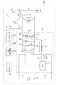
- FIG. 1 is a block diagram schematically illustrating an on-vehicle system including an on-vehicle interrupting current supply device according to a first embodiment.
- FIG. 2 is a flowchart of processing performed by the vehicle-mounted interrupting current supply device.
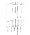
- FIG. 3 is a timing chart showing the operation of the in-vehicle system according to the first embodiment.
- FIG. 4 is a timing chart showing the operation of the in-vehicle system according to the second embodiment.
- the on-vehicle cutoff device to which the application is applied is an on-vehicle cutoff current supply that operates so that the circuit breaker performs a cutoff operation on the power path by allowing energization to the current input section in response to an on operation of the switch.
- a device A transformer having a first winding part and a second winding part, a switching unit that switches between an allowable state that allows energization to the first winding portion and a release state that cancels the allowable state; a capacitor that is electrically connected to an intermediate conductive path between the second winding section and the circuit breaker and receives power from the second winding section; a discharge circuit that discharges the capacitor through a route different from the circuit breaker; a blocking unit that switches between a permission state that allows the discharge circuit to discharge the capacitor and a blocking state that prevents the discharge circuit from discharging the capacitor; a control unit that controls the switching unit and the blocking unit, The control unit performs switching control such that the switching unit alternately repeats switching between the allowable state and the release state, A charging current is supplied to the capacitor from the second winding section in response to the switching control being performed, A discharge current of the capacitor is supplied to the current input section in response to an on-operation of the switch, The vehicle-mounted interrupting current supply device wherein the capacitor is discharged
- the on-vehicle breaking current supply device of [1] above can improve insulation between the drive section (switching section and control section) side and the circuit breaker side due to the presence of the transformer. Furthermore, this vehicle-mounted circuit breaker can input the discharge current from the capacitor to the current input section instead of inputting only the current directly supplied from the second winding section to the current input section. Therefore, this on-vehicle circuit breaker can have both a structure that suppresses the size of the transformer and a structure that allows a certain amount of current to be input to the current input section, and has excellent insulation between the drive section side and the circuit breaker side. It is easy to miniaturize an on-vehicle breaking current supply device that can drive a circuit breaker while increasing the current.
- this on-vehicle interrupting current supply device can discharge the capacitor through a path different from that of the circuit breaker by switching the blocking section to the enabling state, and by switching the blocking section to the blocking state, the capacitor can be discharged through the above-mentioned path of the capacitor. discharge can be suppressed.
- the current input section has a first terminal section and a second terminal section
- the intermediate conductive path is a first conductive path provided between one end of the second winding portion and the first terminal portion, and a first conductive path provided between the other end of the second winding portion and the second terminal portion.
- a second conductive path provided in the The capacitor has one electrode electrically connected to the first conductive path, and the other electrode electrically connected to the second conductive path
- the discharge circuit includes a resistance section connected in parallel to the capacitor between the first conductive path and the second conductive path
- the blocking section includes a second switch provided between the capacitor and the resistor section, and switches to the permission state in response to an ON operation of the second switch, and switches to the enabled state in response to an OFF operation of the second switch.
- the vehicle-mounted interrupting current supply device according to [1], which switches to the blocking state.
- the vehicle-mounted interrupting current supply device in [2] above can more easily realize a configuration in which the capacitor is discharged through a path different from that of the circuit breaker.
- the on-vehicle interrupting current supply device in [3] above can suppress discharge of the capacitor after charging the capacitor to the threshold voltage, and can suppress the current consumption of the battery that supplies power to the first winding. can.
- the control unit After starting the switching control, the control unit stops the switching control when the charging voltage of the capacitor exceeds a threshold voltage, and resumes the switching control when a predetermined restart condition is satisfied.
- the vehicle-mounted interrupting current supply device according to any one of [1] to [3].
- the vehicle-mounted interrupting current supply device of [4] above can prevent the charging voltage of the capacitor from being left in a reduced state.
- the control unit restarts the switching control when the charging voltage of the capacitor becomes equal to or lower than a second threshold voltage, which is smaller than the threshold voltage, after stopping the switching control. Automotive breaking current supply device.
- the vehicle-mounted interrupting current supply device of [5] above easily maintains the charging voltage of the capacitor at the second threshold voltage or higher.
- the vehicle-mounted interrupting current supply device of [6] above can prevent the charging voltage of the capacitor from dropping too much.
- the in-vehicle cut-off current supply device in [7] above can flow current to the discharge circuit in parallel with capacitor charging when performing the first control, thereby increasing the stability of the current during charging. be able to.
- the in-vehicle cut-off current supply device in [8] above can charge the capacitor while preventing discharge from the discharge circuit when performing the second control, so that the charging voltage of the capacitor reaches the target voltage. It is easy to shorten the time required.
- the vehicle-mounted breaking current supply device of [9] above can supply a drive current to the current input section to cause the pyrotechnic circuit breaker to perform a breaking operation.
- This type of pyrotechnic circuit breaker is likely to generate surge voltage near the pyrotechnic circuit breaker during the circuit breaker operation, but the above-mentioned on-vehicle interrupting current supply device prevents the influence of such surge voltage from reaching the drive section. Hateful.
- FIG. 1 shows a vehicle-mounted system 1 including a vehicle-mounted interrupting current supply device 10 according to a first embodiment.
- the vehicle-mounted interrupting current supply device 10 is also referred to as the interrupting current supply device 10.
- the in-vehicle system 1 is a system mounted on the vehicle 100, and is a system that can supply power to various loads.
- the vehicle 100 on which the in-vehicle system 1 is mounted is, for example, a vehicle such as an electric vehicle, a plug-in hybrid vehicle, or a hybrid vehicle, or may be another type of vehicle.
- the in-vehicle system 1 is a system mounted on a vehicle 100.
- the area of the vehicle 100 is conceptually indicated by a dashed-dotted line frame.
- the in-vehicle system 1 includes a battery 4, a cut-off current supply device 10, a cut-off signal generator 40, an in-vehicle cut-off device 2, a starting switch 50, and the like.
- the starting switch 50 corresponds to an ignition switch that starts the engine. If the vehicle 100 is an electric vehicle, this corresponds to a power switch that starts the EV system.
- the battery 4 is an in-vehicle storage battery, and may be configured with a secondary battery such as a lead acid battery or a lithium ion battery, or may be configured with other types of storage batteries.
- a predetermined DC voltage for example, 12V
- the output voltage of the battery 4 is assumed to be V1.
- the power path 9 is a conductive path through which power is transmitted. Although the use of the power path 9 is not limited, for example, it can be configured as a conductive path that supplies power to an on-vehicle load.
- the power path 9 includes a first power path 9A connected to one side of the circuit breaker 6 and a second power path 9B connected to the other side of the circuit breaker 6.
- the first power path 9A and the second power path 9B are short-circuited to each other when the circuit breaker 6 is in a conductive state, and are insulated from each other when the circuit breaker 6 is in a disconnected state.
- the connection destinations on the side opposite to the circuit breaker 6 in the first power path 9A and the second power path 9B are omitted.
- the power path 9 is, for example, a conductive path to which a voltage higher than the voltage applied between the conductive paths 5A and 5B is applied.
- the on-vehicle cutoff device 2 is a device for cutting off the power line 9.
- the vehicle-mounted circuit breaker 2 includes a switch 30 and a circuit breaker 6.
- the switch 30 is composed of a semiconductor switch such as an FET (Field Effect Transistor), a mechanical relay, or the like.
- the switch 30 allows current to flow from the capacitor 25 side to the first terminal portion 7A side when the switch 30 is in the on state, and allows current to flow from the capacitor 25 side to the first terminal portion 7A side when the switch 30 is in the off state. Block the flow.
- the switch 30 is in the on state when the cutoff signal generation section 40 is outputting a cutoff signal (on signal), and when the cutoff signal generation section 40 is outputting a release signal (off signal) becomes off state.
- the switch 30 is in the OFF state, the current flow through the switch 30 is interrupted in both directions, and when the switch 30 is in the ON state, the current flow through the switch 30 is allowed in both directions.
- the circuit breaker 6 is configured as a pyrotechnic circuit breaker.
- a known pyrofuse (registered trademark) or other pyrotechnic fuse can be suitably used.
- the circuit breaker 6 includes a current input section 7, conductor sections 8A, 8B, and 8C, an igniter 6A, and a displacement section (not shown).
- the current input section 7 has a first terminal section 7A and a second terminal section 7B, and is a section through which a current flows from the first terminal section 7A to the second terminal section 7B when the switch 30 is in an on state.
- Current input section 7 is insulated from power path 9.
- the conductor portion 8A is a terminal that is connected to the first power path 9A and short-circuited to the first power path 9A.
- the conductor portion 8B is a terminal that is connected to the second power path 9B and short-circuited to the second power path 9B.
- the conductor portion 8C is a conductor that short-circuits the conductor portion 8A and the conductor portion 8B.
- the igniter 6A is a part that functions to cause a small-scale explosion when current flows from the first terminal part 7A toward the second terminal part 7B, and to move the displacement part by this explosion.
- the displacement part is held in a predetermined position before an explosion occurs in the igniter 6A (when the conductor parts 8A, 8B, and 8C are short-circuited to each other), and when an explosion occurs in the igniter 6A, this explosion occurs.
- the conductor portion 8C is displaced to the side of the conductor portion 8C, and functions to cut and shut off the conductor portion 8C.
- the on-vehicle cutoff device 2 is configured such that when the switch 30 is switched to the on state, energization to the current input section 7 is permitted, and a drive current flows to the current input section 7 (specifically, when the drive current flows through the first terminal When the power flows from the section 7A to the second terminal section 7B via the ignition section), the circuit breaker 6 operates to interrupt the power path 9.
- the cutoff signal generator 40 includes a signal generator 41 and a first insulating element 42.
- the signal generator 41 is a device that can perform the operations of providing a cutoff signal (on signal) to the switch 30 via the conductive path 44 and the operation of providing a release signal (off signal) to the switch 30 via the conductive path 44. be.
- the signal generator 41 is electrically connected to the conductive path 43 and can provide a cutoff signal (on signal) and a release signal (off signal) to the conductive path 43.
- One of the cutoff signal and the release signal is a high level signal, and the other is a low level signal.
- the first insulating element 42 is an element that transmits a signal given to the conductive path 43 to the conductive path 44 while insulating the conductive path 43 and the conductive path 44 .
- the insulation method of the first insulation element 42 may be optical insulation, inductive insulation, or capacitive insulation. In either case, when a cutoff signal (on signal) is output from the signal generator 41 to the conductive path 43, a cutoff signal is sent to the switch 30 in a state where the signal generator 41 and the switch 30 are insulated. (on signal) is applied, and the switch 30 is turned on in response to this.
- the signal generator 41 outputs the release signal (off signal) when a predetermined condition for cutting off the power line 9 is satisfied. For example, the signal generator 41 outputs the release signal (off signal) in the normal state when the value of the current flowing through the power path 9 is below the threshold value, and outputs the above-mentioned release signal (off signal) when the value of the current flowing through the power path 9 exceeds the threshold value. It operates to output the cutoff signal (on signal) when a current state occurs.
- the predetermined condition for cutting off the power path 9 is not limited to this example.
- the signal generating device 41 may operate to output the above-mentioned cutting signal (on signal) when the vehicle 100 collides. good.
- the interrupting current supply device 10 includes a control section 13, a changeover switch 14, a transformer 20, a capacitor 25, a resistor section 26, a second switch 27, a voltage detection section 28, and a second switch 27. 2 insulation elements 62.
- the resistance section 26 and the second switch 27 constitute a series configuration section 29 .
- the series configuration section 29 has a configuration in which the resistance section 26 and the second switch 27 are connected in series with each other.
- the interrupting current supply device 10 is a part that functions as a supply source for supplying a driving current to the circuit breaker 6.
- the control unit 13 includes a control device.
- This control device is an information processing device having arithmetic functions and information processing functions, and includes, for example, a CPU and a storage unit.
- the control unit 13 outputs an on signal for turning on the changeover switch 14 and an off signal for turning off changeover switch 14 .
- One of the on signal and the off signal is, for example, a high level signal, and the other is, for example, a low level signal.
- the changeover switch 14 corresponds to an example of a changeover section.
- the changeover switch 14 When the changeover switch 14 is turned on, the changeover switch 14 enters a permissive state in which the first winding portion 21 is allowed to be energized.
- the changeover switch 14 When the changeover switch 14 is turned off, the changeover switch 14 enters a release state in which the permissible state is released. In other words, the changeover switch 14 switches between an allowable state in which energization of the first winding portion 21 is allowed and a release state in which the allowable state is canceled.
- the changeover switch 14 is configured by, for example, a switching element, and more specifically, by a semiconductor switching element such as an FET (Field Effect Transistor).
- the changeover switch 14 is turned on when an on signal is given from the control unit 13, and is switched to the permissible state.
- the changeover switch 14 is turned off when an off signal is given from the control unit 13, and is switched to the cutoff state.
- the changeover switch 14 may be a switching element other than an FET (for example, a bipolar transistor, etc.).
- the transformer 20 is a transformer having a first winding part 21 and a second winding part 22. Both the first winding section 21 and the second winding section 22 are configured as coils. When a current change occurs in the first winding part 21, the transformer 20 generates a voltage in the second winding part 22 according to the current change in the first winding part 21.
- the number of turns N1 of the first winding section 21 may be larger or smaller than the number of turns N2 of the second winding section 22.
- the selector switch 14 is in the permissive state, an input voltage Vin equivalent to the output voltage of the battery 4 is applied to both ends of the first winding portion 21 .
- the first conductive path 51 is a conductive path provided between one end of the second winding portion 22 and the first terminal portion 7A.
- the second conductive path 52 is a conductive path provided between the other end of the second winding portion 22 and the second terminal portion 7B.
- the second conductive path 52 is a conductor portion that short-circuits the other end of the second winding portion 22, the other electrode of the capacitor 25, the other end of the series component 29, and the second terminal portion 7B.
- a portion of the first conductive path 51 closer to the second winding portion 22 than the switch 30 is short-circuited to one end of the second winding portion 22, one electrode of the capacitor 25, and one end of the series component 29. .
- a portion of the first conductive path 51 closer to the circuit breaker 6 than the switch 30 is short-circuited to the first terminal portion 7A.
- the capacitor 25 is electrically connected to a first conductive path 51 and a second conductive path 52, which are intermediate conductive paths between the second winding section 22 and the circuit breaker 6, and receives power from the second winding section 22. It is a receiving element.
- the capacitor 25 has one electrode electrically connected to the first conductive path 51 and the other electrode electrically connected to the second conductive path 52. When the switch 30 is in the on state, current can flow from the capacitor 25 to the first terminal portion 7A via the first conductive path 51.
- the third conductive path 53 corresponds to an example of "a path different from the circuit breaker.”
- the third conductive path 53 is connected in parallel to the capacitor 25 and in parallel to the circuit breaker 6 between the first conductive path 51 and the second conductive path 52 .
- One end of the third conductive path 53 is short-circuited to the first conductive path 51
- the other end of the third conductive path 53 is short-circuited to the second conductive path 52 .
- the resistance section 26 corresponds to an example of a discharge circuit.
- the resistance section 26 has a function of discharging the capacitor 25.
- the resistance section 26 is connected in parallel to the capacitor 25 between the first conductive path 51 and the second conductive path 52, and is connected in parallel to the circuit breaker 6.
- the resistance section 26 is provided in the third conductive path 53.
- the second switch 27 corresponds to an example of a blocking section. When the second switch 27 is turned on, it enters a permission state in which the resistor 26 allows the capacitor 25 to be discharged. When the second switch 27 is turned off, it enters a blocking state that prevents the resistor 26 from discharging the capacitor 25 . That is, the second switch 27 switches between a permission state in which the resistor section 26 is allowed to discharge the capacitor 25 and a blocking state in which the resistor section 26 is prevented from discharging the capacitor 25.
- the second switch 27 is configured, for example, by a switching element, and more specifically, by a semiconductor switching element such as an FET (Field Effect Transistor). The second switch 27 is turned on when an on signal is given from the control section 13, and is switched to the permission state.
- the second switch 27 is turned off when an off signal is applied from the control section 13, and is switched to the blocking state.
- the second switch 27 may be a switching element other than an FET (for example, a bipolar transistor, etc.).
- the second switch 27 is provided on the third conductive path 53. That is, the above-described series configuration section 29 is provided in the third conductive path 53.
- the second insulating element 62 is provided between the second switch 27 and the control section 13 and insulates the control section 13 and the second switch 27.
- the control unit 13 performs an operation of providing a permission signal (on signal) to the second switch 27 via the conductive path 64 and an operation of providing a blocking signal (off signal) to the second switch 27 via the conductive path 64. obtain.
- the control unit 13 is electrically connected to the conductive path 63 and can provide a permission signal (on signal) and a blocking signal (off signal) to the conductive path 63.
- One of the permission signal and the blocking signal is a high level signal, and the other is a low level signal.
- the second insulating element 62 is an element that insulates the conductive path 63 and the conductive path 64 and transmits a signal given to the conductive path 63 to the conductive path 64.
- the insulation method of the second insulation element 62 may be optical insulation, inductive insulation, or capacitive insulation. In either case, when a permission signal (ON signal) is output from the control unit 13 to the conductive path 63, the control unit 13 and the second switch 27 are insulated, and the second switch 27 is A permission signal (on signal) is given, and the second switch 27 is turned on in response.
- the voltage detection unit 28 has a function of detecting the charging voltage of the capacitor 25.
- the voltage detection section 28 is configured, for example, as a known voltage detection circuit.
- the voltage detection unit 28 detects the voltage between the first conductive path 51 and the second conductive path 52.
- the voltage detection unit 28 may or may not divide the voltage to be detected.
- the voltage detection unit 28 outputs a signal that allows the detection value to be specified to the control unit 13.
- the control unit 13 of the interrupting current supply device 10 performs the process shown in FIG. 2 when a predetermined starting condition is satisfied.
- the starting condition is, for example, that the starting switch 50 that starts the vehicle 100 is switched from an off state to an on state. If the start condition is satisfied, the control unit 13 switches the second switch 27 from the off state (blocking state) to the on state (permitting state) in step S11, and starts the switching control in step S12.
- the control section 13 starts the switching control, it performs the first control to perform the switching control while keeping the second switch 27 in the blocking state.
- the control unit 13 provides the changeover switch 14 with an on/off signal that alternately repeats an on signal and an off signal. Specifically, the control unit 13 supplies the changeover switch 14 with a PWM signal in which a high level signal is an on signal and a low level signal is an off signal, thereby turning the changeover switch 14 on and off.
- a PWM signal in which a high level signal is an on signal and a low level signal is an off signal, thereby turning the changeover switch 14 on and off.
- an input voltage Vin equivalent to the output voltage of the battery 4 is applied to both ends of the first winding portion 21, and the changeover switch 14 is switched from the on state (allowed state) to the off state (released state), the application of voltage from the battery 4 to both ends of the first winding portion 21 is released.
- the capacitor 25 is discharged in response to the on operation of the switch 30, and a drive current flows to the current input section 7.
- a current corresponding to the operation of the changeover switch 14 flows from the second winding part 22 to the first conductive path 51. is discharged from the capacitor 25 to the current input section 7 while being supplied to the current input section 7.
- the drive current is supplied from the capacitor 25 to the current input section 7 in this manner, a small-scale explosion occurs in the igniter 6A, and the circuit breaker 6 interrupts the power path 9.
- the maximum value of the drive current supplied to the current input section 7 in response to the ON operation of the switch 30 is larger than the maximum value of the charging current supplied to the capacitor 25 when charging the capacitor 25.
- the control unit 13 applies PWM to the changeover switch 14 while adjusting the duty so that such a relationship is achieved.
- the control unit 13 determines whether the charging voltage of the capacitor 25 exceeds the threshold voltage Vth1 in step S13.
- the threshold voltage Vth1 is a value larger than 0V, and is a value larger than the minimum value of the voltage required to drive the circuit breaker 6 (hereinafter also referred to as "driving voltage of the circuit breaker 6").
- step S13 If the control unit 13 determines that the charging voltage of the capacitor 25 does not exceed the threshold voltage Vth1 (NO in step S13), the process returns to step S13. That is, the control unit 13 continues the switching control (more specifically, the first control) until the charging voltage of the capacitor 25 exceeds the threshold voltage Vth1. As a result, charging current is continuously supplied to the capacitor 25.
- control unit 13 determines that the charging voltage of the capacitor 25 exceeds the threshold voltage Vth1 (YES in step S13), it stops the switching control in step S14, and in step S15, the second switch 27 Switch to blocked state. That is, the control unit 13 stops the first control. As a result, the supply of charging current to the capacitor 25 is stopped, and discharge from the capacitor 25 to the resistor section 26 is also prevented.
- the changeover switch 14 enters the off state (released state).
- the switch 30 is switched from the off state to the on state while the changeover switch 14 is maintained in the off state (released state)
- the capacitor 25 is discharged to the current input section 7 .
- a small-scale explosion will occur in the igniter 6A, and the circuit breaker 6 will cut off the power line 9. do.
- the control unit 13 determines in step S16 whether a predetermined restart condition is satisfied.
- the restart condition is, for example, that the charging voltage of the capacitor 25 has become equal to or lower than the second threshold voltage Vth2.
- the second threshold voltage Vth2 is a value smaller than the threshold voltage Vth1.
- the second threshold voltage Vth2 is a value larger than 0V and larger than the minimum value of the drive voltage of the circuit breaker 6.
- step S16 If the control unit 13 determines that the restart condition is not satisfied (NO in step S16), the process returns to step S16. That is, the control unit 13 stops the switching control and maintains the second switch 27 in the off state (blocking state) until the restart condition is satisfied.
- step S16 If the control unit 13 determines that the restart condition is satisfied (YES in step S16), the process returns to step S11. That is, after charging the capacitor 25 until the charging voltage exceeds the threshold voltage Vth1, the control unit 13 performs switching control (more specifically, the first control) to make the charging voltage of the capacitor 25 higher than the threshold voltage Vth1.
- the control unit 13 terminates the process shown in FIG. 2, switches the second switch 27 to the on state (permitted state), and discharges the capacitor 25.
- the termination condition is, for example, that the starting switch 50 that starts the vehicle 100 is switched from an on state to an off state. After discharging the capacitor 25, the control unit 13 returns the second switch 27 to the off state (blocking state).
- the timing of returning to the off state may be when the charging voltage of the capacitor 25 becomes 0V, or when a predetermined discharging time has elapsed after starting discharging.
- the following description relates to a specific example of the operation of the interrupting current supply device 10.
- the starting switch 50 is in the off state
- the second switch 27 is in the off state (blocking state)
- the switching control is stopped, and the charging voltage of the capacitor 25 is 0V.
- the current consumption of the battery 4 is 0A.
- the second switch 27 is turned on (permitted state), and at timing t3, switching control is started.
- the switching control is started, the charging voltage of the capacitor 25 gradually increases. Furthermore, as the charging voltage of the capacitor 25 increases, the current consumption of the battery 4 gradually increases.
- the second switch 27 is switched to the off state (blocking state).
- the charging voltage of the capacitor 25 gradually decreases.
- the restart condition is satisfied and the second switch 27 is switched to the on state (permitted state).
- switching control is started at timing t7.
- the charging voltage of the capacitor 25 increases again, and the current consumption of the battery 4 increases.
- the switching control is stopped and the current consumption of the battery 4 becomes 0A.
- the second switch 27 is switched to the off state (blocking state).
- the interrupting current supply device 10 can improve insulation between the drive unit (control unit 13 and changeover switch 14) side and the circuit breaker 6 side. Furthermore, this in-vehicle interrupter 2 inputs only the current directly supplied from the second winding section 22 to the current input section 7, but inputs the discharge current from the capacitor 25 to the current input section 7. can do. Therefore, this vehicle-mounted circuit breaker 2 can achieve both a configuration in which the size of the transformer 20 is suppressed and a configuration in which a certain amount of current can be input to the current input section 7, and the switch 14 side and the circuit breaker 6 The breaking current supply device 10 that can drive the circuit breaker 6 while improving insulation from the other side can be easily miniaturized.
- the interrupting current supply device 10 supplies the capacitor from the second winding portion 22 via the first conductive path 51 during a driving operation in which the changeover switch 14 alternately switches between an on state (allowed state) and an off state (released state).
- a charging current can be supplied to 25.
- the switch 30 When the switch 30 is switched from the off state to the on state, current can flow from the capacitor 25 to the first terminal portion 7A via the first conductive path 51, causing the circuit breaker 6 to perform a breaking operation. .
- the cutoff current supply device 10 can suppress discharge of the capacitor 25 after charging the capacitor 25 to the threshold voltage Vth1, and can suppress current consumption due to operating the changeover switch 14.
- the interrupting current supply device 10 can prevent the charging voltage of the capacitor 25 from being left lowered.
- the interrupting current supply device 10 easily maintains the charging voltage of the capacitor 25 at or above the second threshold voltage Vth2.
- the interrupting current supply device 10 can cause current to flow through the resistor section 26 in parallel with charging the capacitor 25, thereby increasing the stability of the current during charging.
- the interrupting current supply device 10 performs a discharging operation from the capacitor 25 as well as discharging from the second winding.
- the current based on section 22 can be matched.
- the breaking current supply device 10 can supply a drive current to the current input section 7 to cause the pyrotechnic circuit breaker (breaker 6) to perform a breaking operation.
- breaker 6 pyrotechnic circuit breaker
- surge voltage is likely to occur near the pyrotechnic circuit breaker during the circuit breaker operation, but in the above-mentioned circuit breaker current supply device 10, the influence of such surge voltage is And it is difficult to reach the selector switch 14) side.
- the restart conditions are not limited to the configuration described in the first embodiment.
- the second embodiment another example of the restart condition will be described. Note that the configuration of the second embodiment is the same as the first embodiment except for the restart conditions.
- the restart condition in the second embodiment is that a predetermined standby time T has elapsed since the switching control was stopped in step S14 in FIG.
- the standby time T is set so that the charging voltage of the capacitor 25 does not fall below the minimum value of the driving voltage of the circuit breaker 6.
- the waiting time T is determined based on, for example, the capacitance of the capacitor 25, the minimum value of the drive voltage of the circuit breaker 6, and the leakage current between the drain and source when the second switch 27 is in the off state (blocking state). Ru.
- the starting switch 50 is in the off state
- the second switch 27 is in the off state (blocking state)
- the switching control is stopped, and the charging voltage of the capacitor 25 is 0V.
- the current consumption of the battery 4 is 0A.
- the start switch 50 is turned on
- the start condition is satisfied.
- the second switch 27 is turned on (permitted state)
- switching control is started.
- the charging voltage of the capacitor 25 gradually increases.
- the current consumption of the battery 4 gradually increases.
- the second switch 27 is switched to the off state (blocking state).
- the charging voltage of the capacitor 25 gradually decreases.
- the restart condition is satisfied and the second switch 27 is switched to the on state (permitted state).
- switching control is started.
- the charging voltage of the capacitor 25 increases again, and the current consumption of the battery 4 increases.
- the switching control is stopped and the current consumption of the battery 4 becomes 0A.
- the second switch 27 is switched to the off state (blocking state).
- control unit performs the first control when performing switching control, but the configuration is not limited to this.
- control section may be configured to perform second control that performs switching control while keeping the blocking section in the blocking state.
- control unit may be configured to selectively perform the first control and the second control.
- step S11 and the processing in step S12 in FIG. 2 may be reversed in order.
- the processing in step S14 and the processing in step S15 in FIG. 2 may be reversed in order.
- Second conductive path 53 ...Third conductive path 62
- Second insulating element 63 ...Conductive path 64
- Consductive path 100 ...Vehicle T...Waiting time Vth1...Threshold voltage Vth2...Second threshold voltage
Landscapes
- Engineering & Computer Science (AREA)
- Power Engineering (AREA)
- Direct Current Feeding And Distribution (AREA)
- Electric Propulsion And Braking For Vehicles (AREA)
- Charge And Discharge Circuits For Batteries Or The Like (AREA)
Priority Applications (4)
| Application Number | Priority Date | Filing Date | Title |
|---|---|---|---|
| CN202280093914.XA CN118891797A (zh) | 2022-04-08 | 2022-04-08 | 车载用切断电流供给装置 |
| JP2024513663A JP7616482B2 (ja) | 2022-04-08 | 2022-04-08 | 車載用遮断電流供給装置 |
| US18/854,747 US20250233400A1 (en) | 2022-04-08 | 2022-04-08 | In-vehicle interrupting current supply device |
| PCT/JP2022/017348 WO2023195153A1 (ja) | 2022-04-08 | 2022-04-08 | 車載用遮断電流供給装置 |
Applications Claiming Priority (1)
| Application Number | Priority Date | Filing Date | Title |
|---|---|---|---|
| PCT/JP2022/017348 WO2023195153A1 (ja) | 2022-04-08 | 2022-04-08 | 車載用遮断電流供給装置 |
Publications (1)
| Publication Number | Publication Date |
|---|---|
| WO2023195153A1 true WO2023195153A1 (ja) | 2023-10-12 |
Family
ID=88242835
Family Applications (1)
| Application Number | Title | Priority Date | Filing Date |
|---|---|---|---|
| PCT/JP2022/017348 Ceased WO2023195153A1 (ja) | 2022-04-08 | 2022-04-08 | 車載用遮断電流供給装置 |
Country Status (4)
| Country | Link |
|---|---|
| US (1) | US20250233400A1 (https=) |
| JP (1) | JP7616482B2 (https=) |
| CN (1) | CN118891797A (https=) |
| WO (1) | WO2023195153A1 (https=) |
Citations (4)
| Publication number | Priority date | Publication date | Assignee | Title |
|---|---|---|---|---|
| JPS6221322A (ja) * | 1985-07-22 | 1987-01-29 | Yaskawa Electric Mfg Co Ltd | パルストランスによるパワ−mos電界効果トランジスタの駆動回路 |
| JP2015195683A (ja) * | 2014-03-31 | 2015-11-05 | 富士電機株式会社 | 過電流遮断装置 |
| US20180147941A1 (en) * | 2016-11-28 | 2018-05-31 | Volkswagen Ag | Electrical fuse, method of operating an electrical fuse and electrical traction network |
| JP2021501551A (ja) * | 2017-10-25 | 2021-01-14 | 日本テキサス・インスツルメンツ合同会社 | パイロヒューズ回路 |
-
2022
- 2022-04-08 CN CN202280093914.XA patent/CN118891797A/zh active Pending
- 2022-04-08 JP JP2024513663A patent/JP7616482B2/ja active Active
- 2022-04-08 WO PCT/JP2022/017348 patent/WO2023195153A1/ja not_active Ceased
- 2022-04-08 US US18/854,747 patent/US20250233400A1/en active Pending
Patent Citations (4)
| Publication number | Priority date | Publication date | Assignee | Title |
|---|---|---|---|---|
| JPS6221322A (ja) * | 1985-07-22 | 1987-01-29 | Yaskawa Electric Mfg Co Ltd | パルストランスによるパワ−mos電界効果トランジスタの駆動回路 |
| JP2015195683A (ja) * | 2014-03-31 | 2015-11-05 | 富士電機株式会社 | 過電流遮断装置 |
| US20180147941A1 (en) * | 2016-11-28 | 2018-05-31 | Volkswagen Ag | Electrical fuse, method of operating an electrical fuse and electrical traction network |
| JP2021501551A (ja) * | 2017-10-25 | 2021-01-14 | 日本テキサス・インスツルメンツ合同会社 | パイロヒューズ回路 |
Also Published As
| Publication number | Publication date |
|---|---|
| JP7616482B2 (ja) | 2025-01-17 |
| JPWO2023195153A1 (https=) | 2023-10-12 |
| US20250233400A1 (en) | 2025-07-17 |
| CN118891797A (zh) | 2024-11-01 |
Similar Documents
| Publication | Publication Date | Title |
|---|---|---|
| US9188101B2 (en) | Power circuit | |
| JP6623937B2 (ja) | リレー装置及び電源装置 | |
| CN108886266B (zh) | 继电器装置及车载系统 | |
| US11843274B2 (en) | Charge control apparatus for controlling charging of an energy storage device via purality of charging paths connected in parallel anssociated energy storage appartus, and an associated charging method | |
| US11309578B2 (en) | Power supply system and method for controlling same | |
| CN113169582A (zh) | 车载用的备用电源控制装置及车载用的备用电源装置 | |
| JP6915430B2 (ja) | 電源システム | |
| JP6460875B2 (ja) | バッテリシステム制御装置 | |
| CN105408621A (zh) | 汽车的电子安全断路器 | |
| CN109075558B (zh) | 继电器装置 | |
| JP2016187236A (ja) | バッテリシステム制御装置 | |
| JP5266892B2 (ja) | 蓄電装置 | |
| JP2016213969A (ja) | 電源供給装置 | |
| JP2010088180A (ja) | 蓄電装置 | |
| JP6541414B2 (ja) | 電源供給装置 | |
| JP7616482B2 (ja) | 車載用遮断電流供給装置 | |
| JP7700952B2 (ja) | 車載用遮断電流供給装置 | |
| JP2016213967A (ja) | 電源供給装置 | |
| JP7769893B2 (ja) | 車載用遮断制御装置 | |
| WO2023152786A1 (ja) | 車載用遮断制御装置 | |
| US20260110730A1 (en) | Power supply control device | |
| WO2024154286A1 (ja) | 車載用遮断電流供給装置 | |
| CN120530549A (zh) | 车载用控制装置 | |
| WO2024154285A1 (ja) | 車載用遮断電流供給装置 | |
| CN119547299A (zh) | 车载用控制装置 |
Legal Events
| Date | Code | Title | Description |
|---|---|---|---|
| 121 | Ep: the epo has been informed by wipo that ep was designated in this application |
Ref document number: 22936551 Country of ref document: EP Kind code of ref document: A1 |
|
| ENP | Entry into the national phase |
Ref document number: 2024513663 Country of ref document: JP Kind code of ref document: A |
|
| WWE | Wipo information: entry into national phase |
Ref document number: 202280093914.X Country of ref document: CN |
|
| WWE | Wipo information: entry into national phase |
Ref document number: 18854747 Country of ref document: US |
|
| NENP | Non-entry into the national phase |
Ref country code: DE |
|
| 122 | Ep: pct application non-entry in european phase |
Ref document number: 22936551 Country of ref document: EP Kind code of ref document: A1 |
|
| WWP | Wipo information: published in national office |
Ref document number: 18854747 Country of ref document: US |