WO2023191048A1 - All-solid-state battery - Google Patents
All-solid-state battery Download PDFInfo
- Publication number
- WO2023191048A1 WO2023191048A1 PCT/JP2023/013537 JP2023013537W WO2023191048A1 WO 2023191048 A1 WO2023191048 A1 WO 2023191048A1 JP 2023013537 W JP2023013537 W JP 2023013537W WO 2023191048 A1 WO2023191048 A1 WO 2023191048A1
- Authority
- WO
- WIPO (PCT)
- Prior art keywords
- solid
- current collecting
- container
- battery
- collecting member
- Prior art date
Links
- 238000007789 sealing Methods 0.000 claims abstract description 45
- 238000010248 power generation Methods 0.000 claims abstract description 38
- 229910052751 metal Inorganic materials 0.000 claims abstract description 36
- 239000002184 metal Substances 0.000 claims abstract description 36
- 239000007784 solid electrolyte Substances 0.000 claims abstract description 29
- 229920000049 Carbon (fiber) Polymers 0.000 claims abstract description 21
- 239000004917 carbon fiber Substances 0.000 claims abstract description 21
- VNWKTOKETHGBQD-UHFFFAOYSA-N methane Chemical compound C VNWKTOKETHGBQD-UHFFFAOYSA-N 0.000 claims abstract description 21
- 238000003825 pressing Methods 0.000 claims abstract description 13
- 239000004020 conductor Substances 0.000 claims description 25
- 239000000463 material Substances 0.000 claims description 14
- OKTJSMMVPCPJKN-UHFFFAOYSA-N Carbon Chemical compound [C] OKTJSMMVPCPJKN-UHFFFAOYSA-N 0.000 claims description 9
- 239000000835 fiber Substances 0.000 claims description 5
- 239000007787 solid Substances 0.000 claims description 5
- 229910052799 carbon Inorganic materials 0.000 claims description 4
- 239000004745 nonwoven fabric Substances 0.000 claims description 4
- 239000002759 woven fabric Substances 0.000 claims description 4
- 239000000843 powder Substances 0.000 claims description 3
- 239000002041 carbon nanotube Substances 0.000 claims description 2
- 229910021393 carbon nanotube Inorganic materials 0.000 claims description 2
- 238000000034 method Methods 0.000 description 7
- 229920005989 resin Polymers 0.000 description 7
- 239000011347 resin Substances 0.000 description 7
- 230000006835 compression Effects 0.000 description 6
- 238000007906 compression Methods 0.000 description 6
- UCKMPCXJQFINFW-UHFFFAOYSA-N Sulphide Chemical compound [S-2] UCKMPCXJQFINFW-UHFFFAOYSA-N 0.000 description 5
- 239000000919 ceramic Substances 0.000 description 5
- PXHVJJICTQNCMI-UHFFFAOYSA-N nickel Substances [Ni] PXHVJJICTQNCMI-UHFFFAOYSA-N 0.000 description 5
- 230000002093 peripheral effect Effects 0.000 description 5
- 239000007774 positive electrode material Substances 0.000 description 5
- 238000004519 manufacturing process Methods 0.000 description 4
- 239000000203 mixture Substances 0.000 description 4
- WHXSMMKQMYFTQS-UHFFFAOYSA-N Lithium Chemical compound [Li] WHXSMMKQMYFTQS-UHFFFAOYSA-N 0.000 description 3
- HBBGRARXTFLTSG-UHFFFAOYSA-N Lithium ion Chemical compound [Li+] HBBGRARXTFLTSG-UHFFFAOYSA-N 0.000 description 3
- RTAQQCXQSZGOHL-UHFFFAOYSA-N Titanium Chemical compound [Ti] RTAQQCXQSZGOHL-UHFFFAOYSA-N 0.000 description 3
- 239000000853 adhesive Substances 0.000 description 3
- 230000001070 adhesive effect Effects 0.000 description 3
- 230000000052 comparative effect Effects 0.000 description 3
- 239000002131 composite material Substances 0.000 description 3
- 239000011521 glass Substances 0.000 description 3
- 229910052744 lithium Inorganic materials 0.000 description 3
- 229910001416 lithium ion Inorganic materials 0.000 description 3
- 239000007769 metal material Substances 0.000 description 3
- 238000000465 moulding Methods 0.000 description 3
- 239000007773 negative electrode material Substances 0.000 description 3
- 229910052759 nickel Inorganic materials 0.000 description 3
- 239000008188 pellet Substances 0.000 description 3
- 229910001220 stainless steel Inorganic materials 0.000 description 3
- IJGRMHOSHXDMSA-UHFFFAOYSA-N Atomic nitrogen Chemical compound N#N IJGRMHOSHXDMSA-UHFFFAOYSA-N 0.000 description 2
- XEEYBQQBJWHFJM-UHFFFAOYSA-N Iron Chemical compound [Fe] XEEYBQQBJWHFJM-UHFFFAOYSA-N 0.000 description 2
- 229910052782 aluminium Inorganic materials 0.000 description 2
- 229910052802 copper Inorganic materials 0.000 description 2
- 239000010949 copper Substances 0.000 description 2
- 229910021389 graphene Inorganic materials 0.000 description 2
- 150000004678 hydrides Chemical class 0.000 description 2
- 239000011810 insulating material Substances 0.000 description 2
- 238000010030 laminating Methods 0.000 description 2
- 229910000625 lithium cobalt oxide Inorganic materials 0.000 description 2
- BFZPBUKRYWOWDV-UHFFFAOYSA-N lithium;oxido(oxo)cobalt Chemical compound [Li+].[O-][Co]=O BFZPBUKRYWOWDV-UHFFFAOYSA-N 0.000 description 2
- 239000005486 organic electrolyte Substances 0.000 description 2
- 239000004033 plastic Substances 0.000 description 2
- 238000009751 slip forming Methods 0.000 description 2
- 239000010935 stainless steel Substances 0.000 description 2
- 239000010936 titanium Substances 0.000 description 2
- VYZAMTAEIAYCRO-UHFFFAOYSA-N Chromium Chemical compound [Cr] VYZAMTAEIAYCRO-UHFFFAOYSA-N 0.000 description 1
- RYGMFSIKBFXOCR-UHFFFAOYSA-N Copper Chemical compound [Cu] RYGMFSIKBFXOCR-UHFFFAOYSA-N 0.000 description 1
- 229910000599 Cr alloy Inorganic materials 0.000 description 1
- 229910000733 Li alloy Inorganic materials 0.000 description 1
- 239000004734 Polyphenylene sulfide Substances 0.000 description 1
- 239000004743 Polypropylene Substances 0.000 description 1
- 229910001128 Sn alloy Inorganic materials 0.000 description 1
- SOXUFMZTHZXOGC-UHFFFAOYSA-N [Li].[Mn].[Co].[Ni] Chemical compound [Li].[Mn].[Co].[Ni] SOXUFMZTHZXOGC-UHFFFAOYSA-N 0.000 description 1
- 229910045601 alloy Inorganic materials 0.000 description 1
- 239000000956 alloy Substances 0.000 description 1
- XAGFODPZIPBFFR-UHFFFAOYSA-N aluminium Chemical compound [Al] XAGFODPZIPBFFR-UHFFFAOYSA-N 0.000 description 1
- 239000005388 borosilicate glass Substances 0.000 description 1
- 229920005549 butyl rubber Polymers 0.000 description 1
- 239000003575 carbonaceous material Substances 0.000 description 1
- 229910052804 chromium Inorganic materials 0.000 description 1
- 239000011651 chromium Substances 0.000 description 1
- 239000010941 cobalt Substances 0.000 description 1
- 229910017052 cobalt Inorganic materials 0.000 description 1
- GUTLYIVDDKVIGB-UHFFFAOYSA-N cobalt atom Chemical compound [Co] GUTLYIVDDKVIGB-UHFFFAOYSA-N 0.000 description 1
- 239000006258 conductive agent Substances 0.000 description 1
- 230000008602 contraction Effects 0.000 description 1
- QHGJSLXSVXVKHZ-UHFFFAOYSA-N dilithium;dioxido(dioxo)manganese Chemical compound [Li+].[Li+].[O-][Mn]([O-])(=O)=O QHGJSLXSVXVKHZ-UHFFFAOYSA-N 0.000 description 1
- 238000007599 discharging Methods 0.000 description 1
- 230000000694 effects Effects 0.000 description 1
- 229920001971 elastomer Polymers 0.000 description 1
- 230000005611 electricity Effects 0.000 description 1
- 238000011156 evaluation Methods 0.000 description 1
- 238000010304 firing Methods 0.000 description 1
- 239000002241 glass-ceramic Substances 0.000 description 1
- 229910002804 graphite Inorganic materials 0.000 description 1
- 239000010439 graphite Substances 0.000 description 1
- 239000012943 hotmelt Substances 0.000 description 1
- 239000011261 inert gas Substances 0.000 description 1
- 238000009413 insulation Methods 0.000 description 1
- 150000002500 ions Chemical class 0.000 description 1
- 229910052742 iron Inorganic materials 0.000 description 1
- 238000005304 joining Methods 0.000 description 1
- 239000001989 lithium alloy Substances 0.000 description 1
- URIIGZKXFBNRAU-UHFFFAOYSA-N lithium;oxonickel Chemical compound [Li].[Ni]=O URIIGZKXFBNRAU-UHFFFAOYSA-N 0.000 description 1
- 150000002739 metals Chemical class 0.000 description 1
- 229910000484 niobium oxide Inorganic materials 0.000 description 1
- URLJKFSTXLNXLG-UHFFFAOYSA-N niobium(5+);oxygen(2-) Chemical compound [O-2].[O-2].[O-2].[O-2].[O-2].[Nb+5].[Nb+5] URLJKFSTXLNXLG-UHFFFAOYSA-N 0.000 description 1
- 229910052757 nitrogen Inorganic materials 0.000 description 1
- 229920006122 polyamide resin Polymers 0.000 description 1
- 229920000069 polyphenylene sulfide Polymers 0.000 description 1
- -1 polypropylene Polymers 0.000 description 1
- 229920001155 polypropylene Polymers 0.000 description 1
- 229920001296 polysiloxane Polymers 0.000 description 1
- 229920002379 silicone rubber Polymers 0.000 description 1
- 239000004945 silicone rubber Substances 0.000 description 1
- 238000003860 storage Methods 0.000 description 1
- 239000000126 substance Substances 0.000 description 1
- 239000002203 sulfidic glass Substances 0.000 description 1
- 229920003002 synthetic resin Polymers 0.000 description 1
- 239000000057 synthetic resin Substances 0.000 description 1
- 229910052719 titanium Inorganic materials 0.000 description 1
- 238000003466 welding Methods 0.000 description 1
- 230000036642 wellbeing Effects 0.000 description 1
Images


Classifications
-
- H—ELECTRICITY
- H01—ELECTRIC ELEMENTS
- H01M—PROCESSES OR MEANS, e.g. BATTERIES, FOR THE DIRECT CONVERSION OF CHEMICAL ENERGY INTO ELECTRICAL ENERGY
- H01M10/00—Secondary cells; Manufacture thereof
- H01M10/05—Accumulators with non-aqueous electrolyte
- H01M10/056—Accumulators with non-aqueous electrolyte characterised by the materials used as electrolytes, e.g. mixed inorganic/organic electrolytes
- H01M10/0561—Accumulators with non-aqueous electrolyte characterised by the materials used as electrolytes, e.g. mixed inorganic/organic electrolytes the electrolyte being constituted of inorganic materials only
- H01M10/0562—Solid materials
-
- H—ELECTRICITY
- H01—ELECTRIC ELEMENTS
- H01M—PROCESSES OR MEANS, e.g. BATTERIES, FOR THE DIRECT CONVERSION OF CHEMICAL ENERGY INTO ELECTRICAL ENERGY
- H01M10/00—Secondary cells; Manufacture thereof
- H01M10/05—Accumulators with non-aqueous electrolyte
- H01M10/058—Construction or manufacture
- H01M10/0585—Construction or manufacture of accumulators having only flat construction elements, i.e. flat positive electrodes, flat negative electrodes and flat separators
-
- H—ELECTRICITY
- H01—ELECTRIC ELEMENTS
- H01M—PROCESSES OR MEANS, e.g. BATTERIES, FOR THE DIRECT CONVERSION OF CHEMICAL ENERGY INTO ELECTRICAL ENERGY
- H01M4/00—Electrodes
- H01M4/02—Electrodes composed of, or comprising, active material
- H01M4/64—Carriers or collectors
- H01M4/66—Selection of materials
-
- H—ELECTRICITY
- H01—ELECTRIC ELEMENTS
- H01M—PROCESSES OR MEANS, e.g. BATTERIES, FOR THE DIRECT CONVERSION OF CHEMICAL ENERGY INTO ELECTRICAL ENERGY
- H01M4/00—Electrodes
- H01M4/02—Electrodes composed of, or comprising, active material
- H01M4/64—Carriers or collectors
- H01M4/70—Carriers or collectors characterised by shape or form
- H01M4/80—Porous plates, e.g. sintered carriers
-
- H—ELECTRICITY
- H01—ELECTRIC ELEMENTS
- H01M—PROCESSES OR MEANS, e.g. BATTERIES, FOR THE DIRECT CONVERSION OF CHEMICAL ENERGY INTO ELECTRICAL ENERGY
- H01M50/00—Constructional details or processes of manufacture of the non-active parts of electrochemical cells other than fuel cells, e.g. hybrid cells
- H01M50/10—Primary casings, jackets or wrappings of a single cell or a single battery
- H01M50/102—Primary casings, jackets or wrappings of a single cell or a single battery characterised by their shape or physical structure
- H01M50/109—Primary casings, jackets or wrappings of a single cell or a single battery characterised by their shape or physical structure of button or coin shape
-
- H—ELECTRICITY
- H01—ELECTRIC ELEMENTS
- H01M—PROCESSES OR MEANS, e.g. BATTERIES, FOR THE DIRECT CONVERSION OF CHEMICAL ENERGY INTO ELECTRICAL ENERGY
- H01M50/00—Constructional details or processes of manufacture of the non-active parts of electrochemical cells other than fuel cells, e.g. hybrid cells
- H01M50/10—Primary casings, jackets or wrappings of a single cell or a single battery
- H01M50/102—Primary casings, jackets or wrappings of a single cell or a single battery characterised by their shape or physical structure
- H01M50/11—Primary casings, jackets or wrappings of a single cell or a single battery characterised by their shape or physical structure having a structure in the form of a chip
-
- H—ELECTRICITY
- H01—ELECTRIC ELEMENTS
- H01M—PROCESSES OR MEANS, e.g. BATTERIES, FOR THE DIRECT CONVERSION OF CHEMICAL ENERGY INTO ELECTRICAL ENERGY
- H01M50/00—Constructional details or processes of manufacture of the non-active parts of electrochemical cells other than fuel cells, e.g. hybrid cells
- H01M50/20—Mountings; Secondary casings or frames; Racks, modules or packs; Suspension devices; Shock absorbers; Transport or carrying devices; Holders
- H01M50/202—Casings or frames around the primary casing of a single cell or a single battery
-
- H—ELECTRICITY
- H01—ELECTRIC ELEMENTS
- H01M—PROCESSES OR MEANS, e.g. BATTERIES, FOR THE DIRECT CONVERSION OF CHEMICAL ENERGY INTO ELECTRICAL ENERGY
- H01M50/00—Constructional details or processes of manufacture of the non-active parts of electrochemical cells other than fuel cells, e.g. hybrid cells
- H01M50/50—Current conducting connections for cells or batteries
- H01M50/531—Electrode connections inside a battery casing
- H01M50/533—Electrode connections inside a battery casing characterised by the shape of the leads or tabs
-
- H—ELECTRICITY
- H01—ELECTRIC ELEMENTS
- H01M—PROCESSES OR MEANS, e.g. BATTERIES, FOR THE DIRECT CONVERSION OF CHEMICAL ENERGY INTO ELECTRICAL ENERGY
- H01M50/00—Constructional details or processes of manufacture of the non-active parts of electrochemical cells other than fuel cells, e.g. hybrid cells
- H01M50/50—Current conducting connections for cells or batteries
- H01M50/531—Electrode connections inside a battery casing
- H01M50/534—Electrode connections inside a battery casing characterised by the material of the leads or tabs
-
- Y—GENERAL TAGGING OF NEW TECHNOLOGICAL DEVELOPMENTS; GENERAL TAGGING OF CROSS-SECTIONAL TECHNOLOGIES SPANNING OVER SEVERAL SECTIONS OF THE IPC; TECHNICAL SUBJECTS COVERED BY FORMER USPC CROSS-REFERENCE ART COLLECTIONS [XRACs] AND DIGESTS
- Y02—TECHNOLOGIES OR APPLICATIONS FOR MITIGATION OR ADAPTATION AGAINST CLIMATE CHANGE
- Y02E—REDUCTION OF GREENHOUSE GAS [GHG] EMISSIONS, RELATED TO ENERGY GENERATION, TRANSMISSION OR DISTRIBUTION
- Y02E60/00—Enabling technologies; Technologies with a potential or indirect contribution to GHG emissions mitigation
- Y02E60/10—Energy storage using batteries
-
- Y—GENERAL TAGGING OF NEW TECHNOLOGICAL DEVELOPMENTS; GENERAL TAGGING OF CROSS-SECTIONAL TECHNOLOGIES SPANNING OVER SEVERAL SECTIONS OF THE IPC; TECHNICAL SUBJECTS COVERED BY FORMER USPC CROSS-REFERENCE ART COLLECTIONS [XRACs] AND DIGESTS
- Y02—TECHNOLOGIES OR APPLICATIONS FOR MITIGATION OR ADAPTATION AGAINST CLIMATE CHANGE
- Y02P—CLIMATE CHANGE MITIGATION TECHNOLOGIES IN THE PRODUCTION OR PROCESSING OF GOODS
- Y02P70/00—Climate change mitigation technologies in the production process for final industrial or consumer products
- Y02P70/50—Manufacturing or production processes characterised by the final manufactured product
Definitions
- This application relates to an all-solid-state battery with excellent electrical connectivity.
- All-solid-state batteries that use solid electrolytes instead of organic electrolytes have been actively developed. All-solid-state batteries are highly safe because they do not use flammable organic electrolytes. In addition, all-solid-state batteries are not only highly safe, but also highly reliable, highly environmentally resistant, and have a long lifespan, so they can continue to contribute to the development of society while also contributing to safety and security. It is expected to be a maintenance-free battery.
- SDGs Sustainable Development Goals
- all-solid-state batteries usually use a laminated electrode assembly in which a solid electrolyte molded body is sandwiched between a positive electrode molded body containing a positive electrode active material and a negative electrode molded body containing a negative electrode active material.
- a laminated electrode assembly in which a solid electrolyte molded body is sandwiched between a positive electrode molded body containing a positive electrode active material and a negative electrode molded body containing a negative electrode active material.
- the body has low flexibility, and the laminated electrode body repeatedly expands and contracts during charging and discharging, making it impossible to maintain good electrical connection between the laminated electrode body and the current collecting member.
- Patent Document 1 proposes a solid battery in which a current collecting member having elasticity and containing a conductive substance is disposed between a laminated electrode body and a conductor part. Further, Patent Document 2 proposes a flat all-solid-state battery in which a flexible conductive porous member is disposed between a laminated electrode body and the inner bottom surface of an outer can or the inner bottom surface of a sealed can.
- the present application was made under the above circumstances, and is intended to provide an all-solid-state battery that can realize good electrical connectivity in the current collection structure of the all-solid-state battery.
- the all-solid-state battery of the present application includes a battery container and a power generation member housed in the battery container, the battery container includes a concave container, and a sealing body, and the concave container has a bottom part and a side wall part. and an opening, the opening of the concave container is covered with the sealing body, and the power generation member includes a positive electrode, a negative electrode, and a solid electrolyte layer disposed between the positive electrode and the negative electrode.
- an elastic member and a current collecting member are stacked in this order from the sealing body side, and the current collecting member is made of a porous metal member or a carbon
- the current collecting member is made of a fibrous porous member and is pressed against the power generating member by the pressing force of the elastic member.
- an all-solid-state battery with excellent electrical connectivity can be provided.
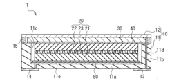
- FIG. 1 is a cross-sectional view schematically showing the all-solid-state battery of the first embodiment.
- FIG. 2 is a cross-sectional view schematically showing the all-solid-state battery of the second embodiment.
- FIG. 3 is a cross-sectional view schematically showing an all-solid-state battery according to a third embodiment.
- the all-solid-state battery of this embodiment includes a battery container and a power generation member housed in the battery container, the battery container includes a concave container, and a sealing body, and the concave container has a bottom portion and a power generation member housed in the battery container.
- the concave container includes a side wall and an opening, the opening of the concave container is covered with the sealing member, and the power generation member includes a positive electrode, a negative electrode, and a solid electrolyte disposed between the positive electrode and the negative electrode.
- an elastic member and a current collecting member are stacked in this order from the sealing member side between the power generation member and the inner bottom surface of the sealing member, and the current collecting member is a porous metal member.
- the power collecting member is made of a carbon fiber porous member, and the current collecting member is pressed against the power generating member by the pressing force of the elastic member.
- an elastic member and a current collecting member formed from a porous metal member or a carbon fiber porous member are disposed between the power generating member and the inner bottom surface of the sealing member to collect current. Since the member is pressed and compressed by the power generating member by the pressing force of the elastic member, even if the power generating member itself does not have flexibility, the current collecting member itself can be flexibly deformed by the pressing force, and Even if there is some unevenness on the surface of the power generation member, the current collection member can absorb the unevenness, so that the electrical contact between the power generation member and the current collection member is good, and the electricity between the power generation member and the current collection member is improved. Connectivity can be improved.
- a current collecting member made of a porous metal member or a carbon fiber porous member is further disposed between the power generating member and the bottom surface of the concave container. Since the pressing force of the elastic member also acts between the power generation member and the bottom of the concave container, good electrical contact is achieved between the power generation member and the current collecting member on the concave container side as well, and as a result, the entire battery This can improve electrical connectivity between the power generation member and the current collection member.
- the power generation member may be composed of a laminate including a positive electrode, a negative electrode, and a solid electrolyte layer. This type of laminate repeatedly expands and contracts as the battery charges and discharges, but the elastic member repeatedly compresses and restores itself in response to the expansion and contraction of the laminate, thereby allowing the laminate and current collecting member to A good electrical connection can be maintained with the
- the power generation member may be composed of a flat battery including a positive electrode, a negative electrode, and a solid electrolyte layer. Although this flat battery does not have flexibility, the current collecting member itself can be flexibly deformed by pressing force, so electrical contact between the flat battery and the current collecting member is good, and the flat battery and the current collecting member can be flexibly deformed. Electrical connectivity with electrical components can be improved.
- the current collecting member is electrically connected to a conductor part, and the conductor part is electrically connected to a connection terminal part of the battery container. Thereby, the electric power generated from the power generation member can be led to the outside.
- the concave container and the sealing body may be bonded together with an adhesive, or may be fixed by welding through a seal ring.
- the materials of the concave container and the sealing body are not particularly limited, and various materials can be used, such as resin, glass (borosilicate glass, glass ceramics, etc.), metal, and ceramic. It may also be a composite material in which ceramic or glass powder is dispersed in a resin.
- the concave container is made of a metal material
- the inner surface of the bottom and the inner surface of the side wall of the concave container may be covered with an insulating material such as a resin material or glass in order to ensure insulation between the concave container and the power generation member. desirable.
- FIG. 1 is a cross-sectional view schematically showing the all-solid-state battery of the first embodiment.
- an all-solid-state battery 1 includes a battery container 10 and a laminate 20 (power generation member) made up of power generation elements housed within the battery container 10.
- the battery container 10 includes a concave container 11 and a sealing body 12.
- the concave container 11 includes a bottom portion 11a, a side wall portion 11b, and an opening 11c. covered.
- the battery container 10 also includes a connection terminal portion 13 and a connection terminal portion 14 .
- the laminate 20 includes a positive electrode 21 , a negative electrode 22 , and a solid electrolyte layer 23 disposed between the positive electrode 21 and the negative electrode 22 .
- an elastic sheet 30 (elastic member) and a current collecting member 40 are stacked in this order from the sealing body 12 side.
- the current collecting member 40 is pressed against the laminate 20 by the pressing force of the elastic sheet 30.
- a current collecting member 50 is also arranged between the stacked body 20 and the bottom surface portion 11a of the concave container 11. Both the current collecting member 40 and the current collecting member 50 are formed from a porous metal member or a carbon fiber porous member.
- the concave container 11 is made of ceramic.
- the concave container 11 includes a circular bottom portion 11a and a cylindrical side wall portion 11b that is formed continuously from the outer periphery of the bottom portion 11a and has a space for accommodating the laminate 20 therein.
- the side wall portion 11b is provided so as to extend substantially perpendicularly to the bottom surface portion 11a when viewed in longitudinal section.
- a conductor portion 11d is formed inside the side wall portion 11b.
- the conductor portion 11d is conductively connected to the current collecting member 40 and the connection terminal portion 13, so that the negative electrode 22 of the laminate 20 and the connection terminal portion 13 are electrically connected.
- a conductor portion 11e is formed inside the bottom surface portion 11a.
- the conductor portion 11e extends above the inner bottom surface of the bottom portion 11a so as to be conductively connected to the current collecting member 50, and thereby the positive electrode 21 of the laminate 20 and the connection terminal portion 14 are electrically connected.
- a method for manufacturing the concave container 11 will be described later.
- the concave container 11 is not limited to ceramic, and may be made of an insulating material such as synthetic resin. Further, the concave container 11 is not limited to a circular shape in plan view, but may be a square shape, an elliptical shape, or a polygonal shape.
- the sealing body 12 is a circular thin metal plate that covers the opening 11c of the concave container 11. As shown in FIG. 1, the sealing body 12 is joined (seamed) to the concave container 11 by a circular frame-shaped seal ring 15 disposed between the lower surface of its outer peripheral end and the upper end of the side wall 11b of the concave container 11. welded). Thereby, the internal space of the battery container 10 is completely sealed.
- the interior space of the battery container 10 is preferably in a vacuum atmosphere or an inert gas atmosphere such as nitrogen in consideration of the influence on the laminate 20, which is a power generation element. Note that the sealing body 12 is not limited to a thin metal plate as long as it can cover the opening 11c of the concave container 11.
- the sealing body 12 is not limited to a circular shape, but can be variously changed to a rectangular shape, an elliptical shape, a polygonal shape, etc. depending on the shape of the concave container 11 in a plan view. Further, the sealing body 12 may have a shape other than a flat plate. Note that the sealing body 12 may be bonded to the concave container 11 with an adhesive, and the method of joining the sealing body 12 and the concave container 11 is not particularly limited.
- connection terminal portion 13 is arranged on the outer surface of the bottom portion 11a of the concave container 11.
- the connection terminal portion 13 is electrically connected to the negative electrode 22 via the conductor portion 11d and the current collecting member 40. Therefore, the conductor portion 11d and the current collecting member 40 become a conduction path that connects the connection terminal portion 13 and the negative electrode 22, and the connection terminal portion 13 functions as a negative electrode terminal.
- connection terminal portion 14 is arranged on the outer surface of the bottom surface portion 11a of the concave container 11 away from the connection terminal portion 13.
- the connection terminal portion 14 is electrically connected to the positive electrode 21 via the conductor portion 11e and the current collecting member 50. Therefore, the conductor portion 11e and the current collecting member 50 serve as a conduction path that connects the connection terminal portion 14 and the positive electrode 21, and the connection terminal portion 14 functions as a positive electrode terminal.
- the arrangement of the connecting terminal portion 13 and the connecting terminal portion 14 is not limited to the above, and may be arranged on the outer surface of the side wall portion 11b of the concave container 11.
- a method for manufacturing the concave container 11 will be explained. First, a metal paste is printed and coated on a ceramic green sheet to form a printed pattern that will become the conductor portions 11d and 11e. Next, a plurality of green sheets having these printed patterns formed thereon are laminated and fired. Thereby, the concave container 11 having the conductor portion 11d and the conductor portion 11e inside can be manufactured. Note that the connecting terminal portion 13 and the connecting terminal portion 14 can also be formed by a printed pattern of this metal paste.
- a laminate 20 made of power generation elements constituting a power generation member includes a positive electrode 21 made of a molded body of a positive electrode mixture containing a positive electrode active material, a negative electrode 22 made of a molded body of a negative electrode mixture containing a negative electrode active material, and a solid electrolyte. It is formed by laminating layers 23 and 23. Solid electrolyte layer 23 is arranged between positive electrode 21 and negative electrode 22.
- the laminate 20 is formed into a cylindrical shape. In the laminate 20, a positive electrode 21, a solid electrolyte layer 23, and a negative electrode 22 are laminated in this order from the bottom 11a side (lower side in the drawing) of the concave container 11.
- the laminate 20 is not limited to a cylindrical shape, and can be modified in various ways according to the shape of the concave container 11. Further, the laminate 20 may include a plurality of laminates. In this case, the plurality of laminates may be stacked so as to be connected in series.
- the type of positive electrode active material used in the positive electrode 21 is not particularly limited as long as it functions as a positive electrode component of the power generation element, and examples thereof include lithium cobalt oxide, lithium nickel oxide, lithium manganate, and lithium nickel cobalt manganese composite. Oxides, olivine-type composite oxides, etc. can be used, and these may be mixed as appropriate. Specifically, in the case of a positive electrode used in a lithium ion secondary battery, for example, lithium cobalt oxide, a sulfide-based solid electrolyte, and graphene as a conductive agent are mixed in a mass ratio of 65:30:5. A positive electrode molded body (pellet) formed by molding a positive electrode mixture into a cylindrical shape can be used as the positive electrode.
- the type of negative electrode active material used for the negative electrode 22 is not particularly limited as long as it functions as a negative electrode component of the power generation element, and examples thereof include lithium titanate; metallic lithium, lithium alloy; graphite, low-crystalline carbon, etc. Carbon materials; oxides such as SiO can be used, and these may be mixed as appropriate.
- a negative electrode used in a lithium ion secondary battery for example, LTO (Li 4 Ti 5 O 12 , lithium titanate), a sulfide-based solid electrolyte, and graphene are mixed at a mass ratio of 50.
- a negative electrode molded body (pellet) obtained by molding a negative electrode mixture containing a ratio of :40:10 into a cylindrical shape can be used as a negative electrode.
- the solid electrolyte layer 23 can be used as a molded body (pellet) formed by molding a solid electrolyte into a cylindrical shape.
- the type of solid electrolyte used in the solid electrolyte layer 23 is not particularly limited, and for example, hydride solid electrolytes, sulfide solid electrolytes, oxide solid electrolytes, etc. can be used, but ion conductive solid electrolytes may be used. From this point of view, sulfide-based solid electrolytes, particularly argyrodite-type sulfide-based solid electrolytes, are preferably used.
- the surface of the positive electrode active material is preferably coated with a lithium ion conductive material such as niobium oxide in order to prevent reaction with the positive electrode active material.
- the solid electrolyte contained in the positive electrode 21 and the negative electrode 22 described above is not particularly limited, and may be a hydride-based solid electrolyte, an oxide-based solid electrolyte, or the like.
- the current collecting member 40 is a sheet material having a circular shape in plan view and made of a porous metal member or a carbon fiber porous member installed in the opening 11c of the concave container 11 of the battery container 10. Further, the current collecting member 40 is pressed against the negative electrode 22 of the laminate 20 by the elastic sheet 30, and the end of the current collecting member 40 is electrically connected to the conductor portion 11d. Thereby, the current collecting member 40 functions as a current collector and forms part of a conduction path that electrically connects the negative electrode 22 and the connection terminal portion 13.
- the current collecting member 40 is supported by the upper end of the side wall 11b of the concave container 11 and covers the entire surface of the opening 11c of the concave container 11, but if a conductive path with the connection terminal portion 13 can be secured,
- the shape and size can be set as appropriate.
- the shape of the current collecting member 40 is not limited to a circular shape in a plan view, but may be a rectangular shape or a polygonal shape.
- the current collecting member 50 is a sheet material having a circular shape in plan view and made of a porous metal member or a carbon fiber porous member installed on the bottom portion 11a side of the concave container 11 of the battery container 10. Further, the current collecting member 50 is pressed against the positive electrode 21 of the laminate 20, and the entire surface of the current collecting member 50 is electrically connected to the conductor portion 11e. Thereby, the current collecting member 50 functions as a current collector and forms part of a conduction path that electrically connects the positive electrode 21 and the connection terminal portion 14.
- the type of porous metal member forming the current collecting member is not particularly limited as long as it can be compressed by pressing force, but examples thereof include a metal powder sintered base material, a metal fiber sintered base material, a foamed metal base material etc. can be used.
- metal types that can be used for the porous metal member include Ni, Al, Cu, Ni--Cr alloy, Ni--Sn alloy, and the like.
- the porosity of the porous metal member before compression is not particularly limited as long as its compressibility can be maintained, but it can be set to, for example, 50 to 98%.
- the thickness of the porous metal member after compression is not particularly limited, but can be set to, for example, 0.05 to 1 mm.
- a conductive plastic body can also be used as the porous metal member.
- the carbon fiber porous member forming the current collecting member is not particularly limited in type as long as it can be compressed by pressing force, but examples include carbon felt; woven or nonwoven fabric of carbon fiber; woven fabric of carbon nanotube fibers. Alternatively, nonwoven fabric or the like can be used.
- the fiber diameter of the carbon fiber used in the carbon fiber porous member is preferably 1 nm to 1 ⁇ m.
- the basis weight of the carbon fiber porous member is preferably 5 to 200 g/m 2 .
- the thickness of the carbon fiber porous member after compression is not particularly limited, but can be set to, for example, 0.05 to 1 mm.
- a conductive plastic body can also be used as the carbon fiber porous member.
- the elastic sheet 30 is a circular sheet material disposed between the current collecting member 40 and the inner bottom surface of the sealing body 12 in a plan view.
- the elastic sheet 30 is compressed because it is pushed into the interior of the battery container 10 by the sealing body 12, and the elastic sheet 30 closes the concave container due to its elastic force.
- the laminated body 20 is pressed together with the current collecting members 40 and 50 in the direction of the bottom surface 11 a of the laminate 11 . Thereby, the laminated body 20 and the current collecting members 40 and 50 can maintain good electrical connection.
- the shape of the elastic sheet 30 is not limited to a circular shape in plan view, but may be a square shape. By having the same shape as the current collecting member 40, the elastic sheet 30 can press the current collecting member 40 over the entire surface.
- the elastic sheet 30 is arranged to cover the entire surface of the current collecting member 40. This allows the elastic sheet 30 to press the current collecting member 40 over a wide area, and by electrically connecting the laminate 20, which is a power generating member, and the current collecting member 40 over a wider area, the laminate The electrical connectivity between the current collecting member 20 and the current collecting member 40 can be further improved. Note that the shape and size of the elastic sheet 30 may be set as appropriate unless there is a problem with the electrical connection between the laminate 20 and the current collecting member 40 or between the current collecting member 40 and the conductor portion 11d. be able to.
- the type of elastic sheet 30 is not particularly limited, for example, an insulating elastic sheet such as a silicone rubber sheet, a silicone sponge sheet, a butyl rubber sheet, or a fluororesin rubber sheet is used.
- the thickness of the elastic sheet 30 after compression is not particularly limited, but can be set to, for example, 0.05 to 1 mm. Further, the thickness of the elastic sheet 30 before compression is not particularly limited, but may be set to be 0.1 to 2 mm larger than the thickness after compression.
- the laminate 20 may be housed in the internal space of the battery container 10 with its top and bottom upside down.
- the connection terminal portion 13 functions as a positive electrode terminal
- the connection terminal portion 14 functions as a negative electrode terminal.
- FIG. 2 is a cross-sectional view schematically showing the all-solid-state battery of the second embodiment.
- the all-solid-state battery 1 of the present embodiment shown in FIG. 2 is the all-solid-state battery of the first embodiment, except that the laminate 20 of the all-solid-state battery 1 of the first embodiment shown in FIG. 1, therefore, in the all-solid-state battery 1 of this embodiment, the description of the same configuration as the all-solid-state battery 1 of the first embodiment will be basically omitted, and the all-solid-state battery 1 of the first embodiment will not be described. Only the configurations that are different from the above will be explained.
- the all-solid-state battery 1 of this embodiment accommodates a flat battery 60 as a power generation member in the internal space of the battery container 10.
- the flat battery 60 includes an outer can 61, a sealed can 62, a laminate 20 made of the power generation element described in the first embodiment, and a gasket 63.
- flat batteries that are larger in diameter than height are called coin batteries or button batteries, but there is no clear difference between coin batteries and button batteries.
- the flat batteries used in this embodiment include both coin-shaped batteries and button-shaped batteries. Further, the shape of this flat battery when viewed from above is not particularly limited and may be circular, square, rectangular, or the like.
- the outer can 61 includes a circular flat portion 61a and a cylindrical side wall portion 61b that is continuously formed from the outer periphery of the flat portion 61a.
- the cylindrical side wall portion 61b is provided so as to extend substantially perpendicularly to the flat portion 61a when viewed in longitudinal section.
- the outer can 61 is made of a metal material such as stainless steel.
- the sealing can 62 includes a circular flat portion 62a and a cylindrical peripheral wall portion 62b that is continuously formed from the outer periphery of the flat portion 62a.
- the opening of the sealed can 62 faces the opening of the outer can 61.
- the sealing can 62 is made of a metal material such as stainless steel.
- the outer can 61 and the sealing can 62 are connected to each other via a gasket 63 arranged between the cylindrical side wall 61b of the outer can 61 and the peripheral wall 62b of the sealing can 62 after the laminate 20 is accommodated in the internal space. It is caulked. Thereby, the internal space formed by the outer can 61 and the sealing can 62 is in a sealed state.
- the outer can 61 and the sealed can 62 are not limited to circular shapes in a plan view, but can be modified into various shapes such as elliptical shapes or polygonal shapes.
- the gasket 63 is made of a resin material such as polyamide resin, polypropylene resin, or polyphenylene sulfide resin.
- the method for sealing the internal space formed by the outer can 61 and the sealing can 62 is not limited to caulking via the gasket 63, and may be performed by other methods.
- the cylindrical side wall portion 61b of the outer can 61 and the peripheral wall portion 62b of the sealing can 62 may be joined with a hot-melt resin, an adhesive, or the like interposed therebetween for sealing.
- the flat battery 60 may be housed in the internal space of the battery container 10 with its top and bottom upside down.
- the connection terminal portion 13 functions as a positive electrode terminal
- the connection terminal portion 14 functions as a negative electrode terminal.
- FIG. 3 is a cross-sectional view schematically showing an all-solid-state battery according to a third embodiment.
- the all-solid-state battery 1 of this embodiment shown in FIG. 3 uses an elastic conductive plate 70 in place of the elastic sheet 30 of the all-solid-state battery 1 of the first embodiment shown in FIG. 1, and the concave container 11 is shown in FIG. Except for the change in shape, it has almost the same configuration as the all-solid-state battery 1 of the first embodiment, so the all-solid-state battery 1 of this embodiment basically has the same configuration as the all-solid-state battery 1 of the first embodiment.
- the explanation will be omitted, and only the configurations that are different from the all-solid-state battery 1 of the first embodiment will be explained.
- the side wall portion 11b of the concave container 11 has a support portion 11f that supports the elastic conductive plate 70.
- the support part 11f is formed at the upper end of the inner circumferential surface of the side wall part 11b, and is a projecting part that projects inward in the radial direction.
- the conductor portion 11d is formed inside the side wall portion 11b and is exposed on the lower surface and side surface of the support portion 11f.
- the conductor portion 11d is conductively connected to the current collecting member 40 via the elastic conductive plate 70, and is further conductively connected to the connecting terminal portion 13, so that the negative electrode 22 of the laminate 20 and the connecting terminal portion 13 are electrically connected. .
- the method for manufacturing the concave container 11 is almost the same as in the first embodiment, but the above-mentioned support portion 11f is formed by laminating and firing a plurality of green sheets having different shapes.
- the current collecting member 40 is formed of a porous metal member or a carbon fiber porous member installed between the laminate 20 and the elastic conductive plate 70 so as to cover the entire upper surface of the laminate 20. It is a shaped sheet material. Further, the current collecting member 40 is pressed against the negative electrode 22 of the laminate 20 by an elastic conductive plate 70.
- the elastic conductive plate 70 is a thin metal plate installed in the opening 11c of the concave container 11.
- the elastic conductive plate 70 includes a supported portion 71 corresponding to the aforementioned supporting portion 11f.
- the supported portion 71 is a hook-shaped locking piece that is locked to the support portion 11f. More specifically, the supported portion 71 extends from the edge of the elastic conductive plate 70 toward the support portion 11f (downward in FIG. 3). Further, the supported portion 71 has a tip that is folded back toward the lower surface of the supporting portion 11f. The tip of the supported portion 71 is in contact with the conductor portion 11d exposed on the lower surface and side surface of the supporting portion 11f.
- the elastic conductive plate 70 functions as a current collector together with the current collecting member 40, and forms part of a conductive path that electrically connects the negative electrode 22 and the connection terminal portion 13.
- the supported part 71 is inserted into a recess provided in the upper end surface of the side wall part 11b, and the elastic conductive plate is pressed against the supported part 71. 70 may be fixed.
- the elastic conductive plate 70 includes a recess 72 facing the upper surface side of the laminate 20.
- the bottom surface of the recess 72 is formed into a planar shape so that the upper surface side of the laminate 20 can be pressed over a wider area. This allows the elastic conductive plate 70 to press the current collecting member 40 over a wide area, and by electrically connecting the laminate 20, which is a power generating member, and the current collecting member 40 over a wider area, the laminate Electrical connectivity between the body 20 and the current collecting member 40 can be further improved.
- Examples of metals constituting the elastic conductive plate 70 include nickel, iron, copper, chromium, cobalt, titanium, aluminum, and alloys thereof, and in order to facilitate the function as a leaf spring, SUS301-CSP and SUS304 are used.
- Stainless steels for springs such as -CSP, SUS316-CSP, SUS420J2-CSP, SUS631-CSP and SUS632J1-CSP are preferably used.
- the thickness of the elastic conductive plate 70 is preferably 0.05 mm or more, and more preferably 0.07 mm or more, in order to maintain the pressing force against the laminate 20 and the current collecting member 40 at a certain level or more. , 0.1 mm or more is particularly preferable.
- the thickness of the elastic conductive plate 70 is preferably 0.5 mm or less, more preferably 0.4 mm or less, and particularly preferably 0.3 mm or less.
- the elastic conductive plate 70 is placed on the upper surface of the laminate with current collecting members after the laminate 20 (laminate with current collecting members) in which the current collecting members 40 and 50 are stacked is housed inside the concave container 11. be placed. With the elastic conductive plate 70 placed on the upper surface of the laminate with a current collecting member, the tip of the supported portion 71 is connected to the current collecting member in the axial direction of the laminate with a current collecting member (vertical direction in FIG. 3). It is positioned between the upper surface of the attached laminate and the lower surface of the support section 11f. Then, while pushing the supported portion 71 of the elastic conductive plate 70 toward the bottom portion 11a of the concave container 11, the tip of the supported portion 71 is locked to the lower surface of the supporting portion 11f.
- the elastic conductive plate 70 presses the stacked body with a current collecting member toward the bottom surface 11a of the concave container 11 by its elastic force. That is, the elastic conductive plate 70 functions as a plate spring. As described above, the configuration is not particularly limited as long as the elastic conductive plate 70 functions as a plate spring that presses the laminate with a current collecting member.
- a gap is formed between the elastic conductive plate 70 and the sealing body 12. That is, the elastic conductive plate 70 and the sealing body 12 are not in contact with each other. Thereby, even if the elastic conductive plate 70 is pushed toward the sealing body 12 due to a change in the volume of the laminate 20 made of power generation elements, contact between the elastic conductive plate 70 and the sealing body 12 can be avoided.
- Example 1 using an elastic conductive plate 70 made of SUS304-CSP of The electrical connection between the elastic conductive plate and the laminate 20 was achieved by Example 2, which was configured in the same manner as 1, and by Comparative Example 1, which was configured such that the elastic conductive plate 70 directly pressed the laminate 20 without using a current collecting member. Connectivity was evaluated. Specifically, for the all-solid-state batteries of Examples 1 and 2 and Comparative Example 1, the AC impedance at 1 kHz was measured at an applied voltage of 10 mV to determine the internal resistance of the batteries. The results are shown in Table 1.
- Example 1 in which a current collecting member made of a porous metal member or a carbon fiber porous member is pressed against a power generation member by the pressing force of an elastic member made of a metal conductive plate It is clear that the all-solid-state battery of Example 2 can achieve better electrical connectivity than the all-solid-state battery of Comparative Example 1 in which the power generation member is directly pressed by the elastic member.
- the laminate 20 made of power generation elements is used as the power generation member, but similarly to the second embodiment described above, a flat battery may be used as the power generation member instead of the laminate 20. In that case as well, the same effects as the all-solid-state battery of this embodiment can be achieved.
Abstract
An all-solid-state battery according to the present application comprises: a battery container; and a laminate body constituting a power generation member stored in the battery container. The battery container has a recessed container and a sealing body. The recessed container has a bottom surface part, a side wall part, and an opening part. The opening part of the recessed container is covered with the sealing body. The laminate body includes a positive electrode, a negative electrode, and a solid electrolyte layer. An elastic sheet and a current collector member are laminated on each other and provided between the laminate body and the inner bottom surface of the sealing body. The current collector member is further provided between the laminate body and the bottom surface part of the recessed container. The current collector member is formed of a porous metal member or a carbon fiber porous member. The current collector member is pressed by the laminate body by means of a pressing force of the elastic sheet.
Description
本願は、電気的接続性に優れた全固体電池に関するものである。
This application relates to an all-solid-state battery with excellent electrical connectivity.
近年、有機電解液に代えて、固体電解質を用いた全固体電池の開発が盛んに行われている。全固体電池は、可燃性の有機電解液を用いないため、高い安全性を備えている。また、全固体電池は、高い安全性だけではなく、高い信頼性及び高い耐環境性を有し、かつ長寿命であるため、社会の発展に寄与すると同時に安心、安全にも貢献し続けることができるメンテナンスフリーの電池として期待されている。全固体電池の社会への提供により、国際連合が制定する持続可能な開発目標(SDGs)の17の目標のうち、目標3(あらゆる年齢のすべての人々の健康的な生活を確保し、福祉を促進する)、目標7(すべての人々の、安価かつ信頼できる持続可能な近代的エネルギーへのアクセスを確保する)、目標11〔包摂的で安全かつ強靭(レジリエント)で持続可能な都市及び人間居住を実現する〕、及び目標12(持続可能な生産消費形態を確保する)の達成に貢献することができる。
In recent years, all-solid-state batteries that use solid electrolytes instead of organic electrolytes have been actively developed. All-solid-state batteries are highly safe because they do not use flammable organic electrolytes. In addition, all-solid-state batteries are not only highly safe, but also highly reliable, highly environmentally resistant, and have a long lifespan, so they can continue to contribute to the development of society while also contributing to safety and security. It is expected to be a maintenance-free battery. By providing all-solid-state batteries to society, we can achieve Goal 3 of the 17 Sustainable Development Goals (SDGs) established by the United Nations (ensure healthy lives and well-being for all people of all ages). Goal 7 (Ensure access to affordable, reliable, sustainable and modern energy for all), Goal 11 (Inclusive, safe, resilient and sustainable cities and human settlements) ] and contribute to the achievement of Goal 12 (ensure sustainable production and consumption patterns).
ところが、全固体電池は、通常、固体電解質の成形体を、正極活物質を含む正極成形体と負極活物質を含む負極成形体とで挟んで形成した積層電極体を用いているため、積層電極体の柔軟性が低く、また、充放電に伴い積層電極体が膨張・収縮を繰り返すことにより、積層電極体と集電部材との電気的接続を良好に維持できない問題がある。
However, all-solid-state batteries usually use a laminated electrode assembly in which a solid electrolyte molded body is sandwiched between a positive electrode molded body containing a positive electrode active material and a negative electrode molded body containing a negative electrode active material. There is a problem in that the body has low flexibility, and the laminated electrode body repeatedly expands and contracts during charging and discharging, making it impossible to maintain good electrical connection between the laminated electrode body and the current collecting member.
この問題を解決するため、特許文献1では、弾性を有しかつ導電性物質を含む集電部材を、積層電極体と導体部との間に配置した固体電池が提案されている。また、特許文献2では、積層電極体と外装缶の内底面又は封口缶の内底面との間に可撓性を有する導電性多孔質部材を配置した扁平形全固体電池が提案されている。
In order to solve this problem, Patent Document 1 proposes a solid battery in which a current collecting member having elasticity and containing a conductive substance is disposed between a laminated electrode body and a conductor part. Further, Patent Document 2 proposes a flat all-solid-state battery in which a flexible conductive porous member is disposed between a laminated electrode body and the inner bottom surface of an outer can or the inner bottom surface of a sealed can.
特許文献1又は2で提案された集電構造を用いることにより、積層電極体と集電部材との電気的接続性をある程度向上させることは可能である。しかし、特許文献1又は2の集電構造を用いた場合であっても、用いる電池容器の形状によっては、積層電極体と集電部材との電気的接続性が不十分となる場合があり、その集電構造について更なる検討が必要であった。
By using the current collecting structure proposed in Patent Document 1 or 2, it is possible to improve the electrical connectivity between the laminated electrode body and the current collecting member to some extent. However, even when the current collecting structure of Patent Document 1 or 2 is used, the electrical connectivity between the laminated electrode body and the current collecting member may be insufficient depending on the shape of the battery container used. Further study was required regarding the current collection structure.
本願は、上記状況下でなされたものであり、全固体電池の集電構造において、良好な電気的接続性を実現できる全固体電池を提供するものである。
The present application was made under the above circumstances, and is intended to provide an all-solid-state battery that can realize good electrical connectivity in the current collection structure of the all-solid-state battery.
本願の全固体電池は、電池容器と、前記電池容器内に収容された発電部材とを含み、前記電池容器は、凹状容器と、封口体とを含み、前記凹状容器は、底面部と側壁部と開口部とを備え、前記凹状容器の前記開口部は、前記封口体で覆われ、前記発電部材は、正極と、負極と、前記正極と前記負極との間に配置された固体電解質層とを含み、前記発電部材と前記封口体の内底面との間に、前記封口体側から弾性部材と集電部材とがこの順に積層されて配置され、前記集電部材は、多孔質金属部材又は炭素繊維多孔質部材から形成され、前記集電部材は、前記弾性部材の押圧力により、前記発電部材に押圧されている。
The all-solid-state battery of the present application includes a battery container and a power generation member housed in the battery container, the battery container includes a concave container, and a sealing body, and the concave container has a bottom part and a side wall part. and an opening, the opening of the concave container is covered with the sealing body, and the power generation member includes a positive electrode, a negative electrode, and a solid electrolyte layer disposed between the positive electrode and the negative electrode. between the power generation member and the inner bottom surface of the sealing body, an elastic member and a current collecting member are stacked in this order from the sealing body side, and the current collecting member is made of a porous metal member or a carbon The current collecting member is made of a fibrous porous member and is pressed against the power generating member by the pressing force of the elastic member.
本願によれば、電気的接続性に優れた全固体電池を提供することができる。
According to the present application, an all-solid-state battery with excellent electrical connectivity can be provided.
本願の全固体電池の実施形態を説明する。本実施形態の全固体電池は、電池容器と、前記電池容器内に収容された発電部材とを含み、前記電池容器は、凹状容器と、封口体とを含み、前記凹状容器は、底面部と側壁部と開口部とを備え、前記凹状容器の前記開口部は、前記封口体で覆われ、前記発電部材は、正極と、負極と、前記正極と前記負極との間に配置された固体電解質層とを含み、前記発電部材と前記封口体の内底面との間に、前記封口体側から弾性部材と集電部材とがこの順に積層されて配置され、前記集電部材は、多孔質金属部材又は炭素繊維多孔質部材から形成され、前記集電部材は、前記弾性部材の押圧力により、前記発電部材に押圧されている。
An embodiment of the all-solid-state battery of the present application will be described. The all-solid-state battery of this embodiment includes a battery container and a power generation member housed in the battery container, the battery container includes a concave container, and a sealing body, and the concave container has a bottom portion and a power generation member housed in the battery container. The concave container includes a side wall and an opening, the opening of the concave container is covered with the sealing member, and the power generation member includes a positive electrode, a negative electrode, and a solid electrolyte disposed between the positive electrode and the negative electrode. an elastic member and a current collecting member are stacked in this order from the sealing member side between the power generation member and the inner bottom surface of the sealing member, and the current collecting member is a porous metal member. Alternatively, the power collecting member is made of a carbon fiber porous member, and the current collecting member is pressed against the power generating member by the pressing force of the elastic member.
本実施形態の全固体電池では、発電部材と封口体の内底面との間に、弾性部材と、多孔質金属部材又は炭素繊維多孔質部材から形成された集電部材とが配置され、集電部材が弾性部材の押圧力により発電部材に押圧されて圧縮されているので、発電部材自体が柔軟性を有さなくても、集電部材自体が押圧力により柔軟に変形可能であり、また、発電部材の表面に多少の凹凸があっても、その凹凸を集電部材が吸収可能であるため、発電部材と集電部材との電気的接触が良好となり、発電部材と集電部材との電気的接続性を向上できる。
In the all-solid-state battery of this embodiment, an elastic member and a current collecting member formed from a porous metal member or a carbon fiber porous member are disposed between the power generating member and the inner bottom surface of the sealing member to collect current. Since the member is pressed and compressed by the power generating member by the pressing force of the elastic member, even if the power generating member itself does not have flexibility, the current collecting member itself can be flexibly deformed by the pressing force, and Even if there is some unevenness on the surface of the power generation member, the current collection member can absorb the unevenness, so that the electrical contact between the power generation member and the current collection member is good, and the electricity between the power generation member and the current collection member is improved. Connectivity can be improved.
また、前記発電部材と前記凹状容器の底面部との間に、多孔質金属部材又は炭素繊維多孔質部材からなる集電部材が更に配置されていることが好ましい。前記弾性部材の押圧力は、発電部材と凹状容器の底面部との間にも作用するため、凹状容器側においても、発電部材と集電部材との電気的接触が良好となり、これにより電池全体で発電部材と集電部材との電気的接続性を向上できる。
Furthermore, it is preferable that a current collecting member made of a porous metal member or a carbon fiber porous member is further disposed between the power generating member and the bottom surface of the concave container. Since the pressing force of the elastic member also acts between the power generation member and the bottom of the concave container, good electrical contact is achieved between the power generation member and the current collecting member on the concave container side as well, and as a result, the entire battery This can improve electrical connectivity between the power generation member and the current collection member.
前記発電部材は、正極と、負極と、固体電解質層とを含む積層体から構成されていてもよい。この種の積層体は、電池の充放電に伴い、膨張・収縮を繰り返すが、前記弾性部材は、積層体の膨張・収縮に対応して圧縮・復元を繰り返すことにより、積層体と集電部材との電気的接続を良好に維持することができる。
The power generation member may be composed of a laminate including a positive electrode, a negative electrode, and a solid electrolyte layer. This type of laminate repeatedly expands and contracts as the battery charges and discharges, but the elastic member repeatedly compresses and restores itself in response to the expansion and contraction of the laminate, thereby allowing the laminate and current collecting member to A good electrical connection can be maintained with the
前記発電部材は、正極と、負極と、固体電解質層とを含む扁平形電池から構成されていてもよい。この扁平形電池は柔軟性を有さないが、集電部材自体が押圧力により柔軟に変形可能であるため、扁平形電池と集電部材との電気的接触が良好となり、扁平形電池と集電部材との電気的接続性を向上できる。
The power generation member may be composed of a flat battery including a positive electrode, a negative electrode, and a solid electrolyte layer. Although this flat battery does not have flexibility, the current collecting member itself can be flexibly deformed by pressing force, so electrical contact between the flat battery and the current collecting member is good, and the flat battery and the current collecting member can be flexibly deformed. Electrical connectivity with electrical components can be improved.
前記集電部材は、導体部と電気的に接続し、その導体部は、電池容器の接続端子部と電気的に接続していることが好ましい。これにより、発電部材から発電された電力を外部に導出できる。
It is preferable that the current collecting member is electrically connected to a conductor part, and the conductor part is electrically connected to a connection terminal part of the battery container. Thereby, the electric power generated from the power generation member can be led to the outside.
前記凹状容器と前記封口体とは、接着剤により接着されてもよく、シールリングを介して溶接して固定されるのであってもよい。
The concave container and the sealing body may be bonded together with an adhesive, or may be fixed by welding through a seal ring.
前記凹状容器及び前記封口体の材質は特に限定されず、例えば、樹脂、ガラス(硼珪酸ガラス、ガラスセラミックスなど)、金属及びセラミックなど、種々のものを使用することができる。樹脂中にセラミックやガラスの粉末が分散された複合材であってもよい。凹状容器を金属材料で構成する場合は、凹状容器と発電部材との絶縁を確保するため、凹状容器の底面部の内面及び側壁部の内面を樹脂材料又はガラスなどの絶縁材で被覆することが望ましい。
The materials of the concave container and the sealing body are not particularly limited, and various materials can be used, such as resin, glass (borosilicate glass, glass ceramics, etc.), metal, and ceramic. It may also be a composite material in which ceramic or glass powder is dispersed in a resin. When the concave container is made of a metal material, the inner surface of the bottom and the inner surface of the side wall of the concave container may be covered with an insulating material such as a resin material or glass in order to ensure insulation between the concave container and the power generation member. desirable.
以下、本実施形態の全固体電池を図面に基づき説明する。
Hereinafter, the all-solid-state battery of this embodiment will be explained based on the drawings.
(第1実施形態)
先ず、第1実施形態の全固体電池について、図1に基づき説明する。図1は、第1実施形態の全固体電池を模式的に示す断面図である。図1において、全固体電池1は、電池容器10と、電池容器10内に収容された発電要素からなる積層体20(発電部材)とを備えている。電池容器10は、凹状容器11と、封口体12とを備え、凹状容器11は、底面部11aと側壁部11bと開口部11cとを備え、凹状容器11の開口部11cは、封口体12で覆われている。また、電池容器10は、接続端子部13及び接続端子部14を備えている。積層体20は、正極21と、負極22と、正極21と負極22との間に配置された固体電解質層23とを備えている。 (First embodiment)
First, the all-solid-state battery of the first embodiment will be described based on FIG. 1. FIG. 1 is a cross-sectional view schematically showing the all-solid-state battery of the first embodiment. In FIG. 1, an all-solid-state battery 1 includes a battery container 10 and a laminate 20 (power generation member) made up of power generation elements housed within the battery container 10. The battery container 10 includes a concave container 11 and a sealing body 12. The concave container 11 includes a bottom portion 11a, a side wall portion 11b, and an opening 11c. covered. The battery container 10 also includes a connection terminal portion 13 and a connection terminal portion 14 . The laminate 20 includes a positive electrode 21 , a negative electrode 22 , and a solid electrolyte layer 23 disposed between the positive electrode 21 and the negative electrode 22 .
先ず、第1実施形態の全固体電池について、図1に基づき説明する。図1は、第1実施形態の全固体電池を模式的に示す断面図である。図1において、全固体電池1は、電池容器10と、電池容器10内に収容された発電要素からなる積層体20(発電部材)とを備えている。電池容器10は、凹状容器11と、封口体12とを備え、凹状容器11は、底面部11aと側壁部11bと開口部11cとを備え、凹状容器11の開口部11cは、封口体12で覆われている。また、電池容器10は、接続端子部13及び接続端子部14を備えている。積層体20は、正極21と、負極22と、正極21と負極22との間に配置された固体電解質層23とを備えている。 (First embodiment)
First, the all-solid-state battery of the first embodiment will be described based on FIG. 1. FIG. 1 is a cross-sectional view schematically showing the all-solid-state battery of the first embodiment. In FIG. 1, an all-solid-
積層体20と封口体12の内底面との間には、封口体12側から弾性シート30(弾性部材)と集電部材40とがこの順に積層されて配置されている。集電部材40は、弾性シート30の押圧力により、積層体20に押圧されている。また、積層体20と凹状容器11の底面部11aとの間にも、集電部材50が配置されている。集電部材40及び集電部材50は、共に多孔質金属部材又は炭素繊維多孔質部材から形成されている。
Between the laminate 20 and the inner bottom surface of the sealing body 12, an elastic sheet 30 (elastic member) and a current collecting member 40 are stacked in this order from the sealing body 12 side. The current collecting member 40 is pressed against the laminate 20 by the pressing force of the elastic sheet 30. Further, a current collecting member 50 is also arranged between the stacked body 20 and the bottom surface portion 11a of the concave container 11. Both the current collecting member 40 and the current collecting member 50 are formed from a porous metal member or a carbon fiber porous member.
凹状容器11は、セラミック製である。凹状容器11は、円形状の底面部11aと、底面部11aの外周から連続して形成され、内部に積層体20を収容するための空間を有する円筒形状の側壁部11bとを備えている。側壁部11bは、縦断面視で、底面部11aに対して略垂直に延びるように設けられている。側壁部11bの内部には、導体部11dが形成されている。導体部11dは、集電部材40と接続端子部13とに導電接続され、これにより積層体20の負極22と接続端子部13とは導通している。また、底面部11aの内部には、導体部11eが形成されている。導体部11eは、集電部材50に導電接続されるように底面部11aの内底面の上に延設され、これにより積層体20の正極21と接続端子部14とは導通している。凹状容器11の製造方法については、後述する。なお、凹状容器11は、セラミック製に限られず、合成樹脂などの絶縁性材料から構成されてもよい。また、凹状容器11は、平面視において円形状に限られず、四角形状、楕円形状及び多角形状であってもよい。
The concave container 11 is made of ceramic. The concave container 11 includes a circular bottom portion 11a and a cylindrical side wall portion 11b that is formed continuously from the outer periphery of the bottom portion 11a and has a space for accommodating the laminate 20 therein. The side wall portion 11b is provided so as to extend substantially perpendicularly to the bottom surface portion 11a when viewed in longitudinal section. A conductor portion 11d is formed inside the side wall portion 11b. The conductor portion 11d is conductively connected to the current collecting member 40 and the connection terminal portion 13, so that the negative electrode 22 of the laminate 20 and the connection terminal portion 13 are electrically connected. Further, a conductor portion 11e is formed inside the bottom surface portion 11a. The conductor portion 11e extends above the inner bottom surface of the bottom portion 11a so as to be conductively connected to the current collecting member 50, and thereby the positive electrode 21 of the laminate 20 and the connection terminal portion 14 are electrically connected. A method for manufacturing the concave container 11 will be described later. Note that the concave container 11 is not limited to ceramic, and may be made of an insulating material such as synthetic resin. Further, the concave container 11 is not limited to a circular shape in plan view, but may be a square shape, an elliptical shape, or a polygonal shape.
封口体12は、凹状容器11の開口部11cを覆う円形状の金属製薄板である。封口体12は、図1に示すように、その外周端部の下面と凹状容器11の側壁部11bの上端との間に配された円形枠状のシールリング15によって凹状容器11に接合(シーム溶接)されている。これにより、電池容器10の内部空間は完全に密閉される。電池容器10の内部空間は、発電要素である積層体20への影響を考慮して真空雰囲気或いは窒素などの不活性ガス雰囲気であることが好ましい。なお、封口体12は、凹状容器11の開口部11cを覆うことができれば、金属製薄板に限られるものではない。封口体12は、円形状に限られず、凹状容器11の平面視における形状に応じて、四角形状、楕円形状及び多角形状などに種々変更することができる。また、封口体12は、平板以外の形状であってもよい。なお、封口体12は、接着剤によって凹状容器11と接着されてもよく、封口体12と凹状容器11との接合方法は特に限定されない。
The sealing body 12 is a circular thin metal plate that covers the opening 11c of the concave container 11. As shown in FIG. 1, the sealing body 12 is joined (seamed) to the concave container 11 by a circular frame-shaped seal ring 15 disposed between the lower surface of its outer peripheral end and the upper end of the side wall 11b of the concave container 11. welded). Thereby, the internal space of the battery container 10 is completely sealed. The interior space of the battery container 10 is preferably in a vacuum atmosphere or an inert gas atmosphere such as nitrogen in consideration of the influence on the laminate 20, which is a power generation element. Note that the sealing body 12 is not limited to a thin metal plate as long as it can cover the opening 11c of the concave container 11. The sealing body 12 is not limited to a circular shape, but can be variously changed to a rectangular shape, an elliptical shape, a polygonal shape, etc. depending on the shape of the concave container 11 in a plan view. Further, the sealing body 12 may have a shape other than a flat plate. Note that the sealing body 12 may be bonded to the concave container 11 with an adhesive, and the method of joining the sealing body 12 and the concave container 11 is not particularly limited.
接続端子部13は、凹状容器11の底面部11aの外面に配置されている。接続端子部13は、導体部11d及び集電部材40を介して負極22に電気的に接続されている。従って、導体部11d及び集電部材40は、接続端子部13と負極22とを導通させる導通経路となり、接続端子部13は、負極端子として機能する。
The connection terminal portion 13 is arranged on the outer surface of the bottom portion 11a of the concave container 11. The connection terminal portion 13 is electrically connected to the negative electrode 22 via the conductor portion 11d and the current collecting member 40. Therefore, the conductor portion 11d and the current collecting member 40 become a conduction path that connects the connection terminal portion 13 and the negative electrode 22, and the connection terminal portion 13 functions as a negative electrode terminal.
接続端子部14は、凹状容器11の底面部11aの外面に接続端子部13から離れて配置されている。接続端子部14は、導体部11e及び集電部材50を介して正極21に電気的に接続されている。従って、導体部11e及び集電部材50は、接続端子部14と正極21とを導通させる導通経路となり、接続端子部14は、正極端子として機能する。
The connection terminal portion 14 is arranged on the outer surface of the bottom surface portion 11a of the concave container 11 away from the connection terminal portion 13. The connection terminal portion 14 is electrically connected to the positive electrode 21 via the conductor portion 11e and the current collecting member 50. Therefore, the conductor portion 11e and the current collecting member 50 serve as a conduction path that connects the connection terminal portion 14 and the positive electrode 21, and the connection terminal portion 14 functions as a positive electrode terminal.
接続端子部13及び接続端子部14の配置は、上記に限定されず、凹状容器11の側壁部11bの外面に配置されてもよい。
The arrangement of the connecting terminal portion 13 and the connecting terminal portion 14 is not limited to the above, and may be arranged on the outer surface of the side wall portion 11b of the concave container 11.
ここで、凹状容器11の製造方法について説明する。先ず、セラミックのグリーンシートに金属ペーストを印刷塗布して導体部11d及び導体部11eとなる印刷パターンを形成する。次に、これらの印刷パターンを形成したグリーンシートを複数積層し、焼成する。これにより、内部に導体部11d及び導体部11eを有する凹状容器11を作製することができる。なお、接続端子部13及び接続端子部14は、この金属ペーストの印刷パターンによって形成することもできる。
Here, a method for manufacturing the concave container 11 will be explained. First, a metal paste is printed and coated on a ceramic green sheet to form a printed pattern that will become the conductor portions 11d and 11e. Next, a plurality of green sheets having these printed patterns formed thereon are laminated and fired. Thereby, the concave container 11 having the conductor portion 11d and the conductor portion 11e inside can be manufactured. Note that the connecting terminal portion 13 and the connecting terminal portion 14 can also be formed by a printed pattern of this metal paste.
発電部材を構成する発電要素からなる積層体20は、正極活物質を含む正極合剤の成形体からなる正極21と、負極活物質を含む負極合剤の成形体からなる負極22と、固体電解質層23とを積層して形成されている。固体電解質層23は、正極21と負極22との間に配置されている。積層体20は、円柱形状に形成されている。積層体20は、凹状容器11の底面部11a側(図示の下方)から正極21、固体電解質層23、負極22の順で積層されている。積層体20は、円柱形状に限られず、凹状容器11の形状に合わせて、種々変更することができる。また、積層体20は、複数の積層体を有していてもよい。この場合、複数の積層体は、直列に接続されるように積層されていてもよい。
A laminate 20 made of power generation elements constituting a power generation member includes a positive electrode 21 made of a molded body of a positive electrode mixture containing a positive electrode active material, a negative electrode 22 made of a molded body of a negative electrode mixture containing a negative electrode active material, and a solid electrolyte. It is formed by laminating layers 23 and 23. Solid electrolyte layer 23 is arranged between positive electrode 21 and negative electrode 22. The laminate 20 is formed into a cylindrical shape. In the laminate 20, a positive electrode 21, a solid electrolyte layer 23, and a negative electrode 22 are laminated in this order from the bottom 11a side (lower side in the drawing) of the concave container 11. The laminate 20 is not limited to a cylindrical shape, and can be modified in various ways according to the shape of the concave container 11. Further, the laminate 20 may include a plurality of laminates. In this case, the plurality of laminates may be stacked so as to be connected in series.
正極21に用いられる正極活物質は、発電要素の正極成分として機能すれば、その種類は特に限定されるものではなく、例えば、コバルト酸リチウム、ニッケル酸リチウム、マンガン酸リチウム、リチウムニッケルコバルトマンガン複合酸化物、オリビン型複合酸化物などが使用でき、これらを適宜混合して使用してもよい。具体的には、リチウムイオン二次電池に用いられる正極の場合には、例えば、コバルト酸リチウムと、硫化物系固体電解質と、導電助剤であるグラフェンとを質量比で65:30:5の割合で含有した正極合剤を円柱形状に成形した正極成形体(ペレット)を正極として用いることができる。
The type of positive electrode active material used in the positive electrode 21 is not particularly limited as long as it functions as a positive electrode component of the power generation element, and examples thereof include lithium cobalt oxide, lithium nickel oxide, lithium manganate, and lithium nickel cobalt manganese composite. Oxides, olivine-type composite oxides, etc. can be used, and these may be mixed as appropriate. Specifically, in the case of a positive electrode used in a lithium ion secondary battery, for example, lithium cobalt oxide, a sulfide-based solid electrolyte, and graphene as a conductive agent are mixed in a mass ratio of 65:30:5. A positive electrode molded body (pellet) formed by molding a positive electrode mixture into a cylindrical shape can be used as the positive electrode.
負極22に用いられる負極活物質は、発電要素の負極成分として機能すれば、その種類は特に限定されるものではなく、例えば、チタン酸リチウム;金属リチウム、リチウム合金;黒鉛、低結晶カーボンなどの炭素材料;SiOなどの酸化物などが使用でき、これらを適宜混合して使用してもよい。具体的には、リチウムイオン二次電池に用いられる負極の場合には、例えば、LTO(Li4Ti5O12、チタン酸リチウム)と、硫化物系固体電解質と、グラフェンとを質量比で50:40:10の割合で含有した負極合剤を円柱形状に成形した負極成形体(ペレット)を負極として用いることができる。
The type of negative electrode active material used for the negative electrode 22 is not particularly limited as long as it functions as a negative electrode component of the power generation element, and examples thereof include lithium titanate; metallic lithium, lithium alloy; graphite, low-crystalline carbon, etc. Carbon materials; oxides such as SiO can be used, and these may be mixed as appropriate. Specifically, in the case of a negative electrode used in a lithium ion secondary battery, for example, LTO (Li 4 Ti 5 O 12 , lithium titanate), a sulfide-based solid electrolyte, and graphene are mixed at a mass ratio of 50. A negative electrode molded body (pellet) obtained by molding a negative electrode mixture containing a ratio of :40:10 into a cylindrical shape can be used as a negative electrode.
固体電解質層23は、固体電解質を円柱状に成形した成形体(ペレット)として用いることができる。固体電解質層23に用いられる固体電解質の種類は、特に限定されるものではなく、例えば、水素化物系固体電解質、硫化物系固体電解質、酸化物系固体電解質などが使用できるが、イオン伝導性の点から硫化物系固体電解質、特にアルジロダイト型の硫化物系固体電解質が好ましく用いられる。硫化物系固体電解質を用いる場合には、正極活物質との反応を防ぐために、正極活物質の表面をニオブ酸化物などのリチウムイオン伝導性材料で被覆することが好ましい。また、前述の、正極21及び負極22に含まれる固体電解質も特に限定されるものではなく、水素化物系固体電解質や酸化物系固体電解質などであってもよい。
The solid electrolyte layer 23 can be used as a molded body (pellet) formed by molding a solid electrolyte into a cylindrical shape. The type of solid electrolyte used in the solid electrolyte layer 23 is not particularly limited, and for example, hydride solid electrolytes, sulfide solid electrolytes, oxide solid electrolytes, etc. can be used, but ion conductive solid electrolytes may be used. From this point of view, sulfide-based solid electrolytes, particularly argyrodite-type sulfide-based solid electrolytes, are preferably used. When using a sulfide-based solid electrolyte, the surface of the positive electrode active material is preferably coated with a lithium ion conductive material such as niobium oxide in order to prevent reaction with the positive electrode active material. Further, the solid electrolyte contained in the positive electrode 21 and the negative electrode 22 described above is not particularly limited, and may be a hydride-based solid electrolyte, an oxide-based solid electrolyte, or the like.
集電部材40は、電池容器10の凹状容器11の開口部11cに設置される多孔質金属部材又は炭素繊維多孔質部材から形成された平面視において円形状のシート材である。また、集電部材40は、積層体20の負極22に弾性シート30により押圧されていると共に、集電部材40の端部は導体部11dと導電接続されている。これにより、集電部材40は、集電体として機能すると共に、負極22と接続端子部13とを電気的に接続する導通経路の一部を為す。集電部材40は、凹状容器11の側壁部11bの上端部に支持され、凹状容器11の開口部11cの全面を覆っているが、接続端子部13との導通経路を確保することができれば、形状や大きさを適宜設定することができる。集電部材40の形状は、平面視で円形状に限られず、四角形状又は多角形状であってもよい。
The current collecting member 40 is a sheet material having a circular shape in plan view and made of a porous metal member or a carbon fiber porous member installed in the opening 11c of the concave container 11 of the battery container 10. Further, the current collecting member 40 is pressed against the negative electrode 22 of the laminate 20 by the elastic sheet 30, and the end of the current collecting member 40 is electrically connected to the conductor portion 11d. Thereby, the current collecting member 40 functions as a current collector and forms part of a conduction path that electrically connects the negative electrode 22 and the connection terminal portion 13. The current collecting member 40 is supported by the upper end of the side wall 11b of the concave container 11 and covers the entire surface of the opening 11c of the concave container 11, but if a conductive path with the connection terminal portion 13 can be secured, The shape and size can be set as appropriate. The shape of the current collecting member 40 is not limited to a circular shape in a plan view, but may be a rectangular shape or a polygonal shape.
集電部材50は、電池容器10の凹状容器11の底面部11a側に設置される多孔質金属部材又は炭素繊維多孔質部材から形成された平面視において円形状のシート材である。また、集電部材50は、積層体20の正極21に押圧されていると共に、集電部材50の全面が導体部11eと導電接続されている。これにより、集電部材50は、集電体として機能すると共に、正極21と接続端子部14を電気的に接続する導通経路の一部を為す。
The current collecting member 50 is a sheet material having a circular shape in plan view and made of a porous metal member or a carbon fiber porous member installed on the bottom portion 11a side of the concave container 11 of the battery container 10. Further, the current collecting member 50 is pressed against the positive electrode 21 of the laminate 20, and the entire surface of the current collecting member 50 is electrically connected to the conductor portion 11e. Thereby, the current collecting member 50 functions as a current collector and forms part of a conduction path that electrically connects the positive electrode 21 and the connection terminal portion 14.
上記集電部材を形成する多孔質金属部材は、押圧力により圧縮可能であれば、その種類は特に限定されないが、例えば、金属粉末焼結基材、金属繊維焼結基材、発泡金属基材などを用いることができる。多孔質金属部材に使用できる金属の種類は、例えば、Ni、Al、Cu、Ni-Cr合金、Ni-Sn合金などが挙げられる。多孔質金属部材の圧縮前の空隙率は、その圧縮性を保持できれば特に限定されないが、例えば、50~98%に設定できる。また、多孔質金属部材の圧縮後の厚さも特に限定されないが、例えば、0.05~1mmに設定できる。多孔質金属部材としては、導電性を有する塑性体を用いることもできる。
The type of porous metal member forming the current collecting member is not particularly limited as long as it can be compressed by pressing force, but examples thereof include a metal powder sintered base material, a metal fiber sintered base material, a foamed metal base material etc. can be used. Examples of metal types that can be used for the porous metal member include Ni, Al, Cu, Ni--Cr alloy, Ni--Sn alloy, and the like. The porosity of the porous metal member before compression is not particularly limited as long as its compressibility can be maintained, but it can be set to, for example, 50 to 98%. Furthermore, the thickness of the porous metal member after compression is not particularly limited, but can be set to, for example, 0.05 to 1 mm. A conductive plastic body can also be used as the porous metal member.
上記集電部材を形成する炭素繊維多孔質部材は、押圧力により圧縮可能であれば、その種類は特に限定されないが、例えば、カーボンフェルト;カーボン繊維の織布又は不織布;カーボンナノチューブ繊維の織布又は不織布などを用いることができる。炭素繊維多孔質部材で用いる炭素繊維の繊維径は、1nm~1μmが好ましい。炭素繊維多孔質部材の目付けは、5~200g/m2であることが好ましい。また、炭素繊維多孔質部材の圧縮後の厚さは特に限定されないが、例えば、0.05~1mmに設定できる。炭素繊維多孔質部材としては、導電性を有する塑性体を用いることもできる。
The carbon fiber porous member forming the current collecting member is not particularly limited in type as long as it can be compressed by pressing force, but examples include carbon felt; woven or nonwoven fabric of carbon fiber; woven fabric of carbon nanotube fibers. Alternatively, nonwoven fabric or the like can be used. The fiber diameter of the carbon fiber used in the carbon fiber porous member is preferably 1 nm to 1 μm. The basis weight of the carbon fiber porous member is preferably 5 to 200 g/m 2 . Further, the thickness of the carbon fiber porous member after compression is not particularly limited, but can be set to, for example, 0.05 to 1 mm. A conductive plastic body can also be used as the carbon fiber porous member.
弾性シート30は、集電部材40と封口体12の内底面との間に配置されている平面視において円形状のシート材である。弾性シート30は、凹状容器11の開口部11cに封口体12を接合する際に、封口体12により電池容器10の内部方向に押し込まれるため圧縮され、弾性シート30は、その弾性力によって凹状容器11の底面部11aの方向へと積層体20を集電部材40、50と共に押圧する。これにより、積層体20と集電部材40、50とは、良好な電気的接続を維持させることができる。弾性シート30の形状は、平面視で円形状に限られず、四角形状であってもよい。弾性シート30は、集電部材40と同形状とすることで、集電部材40を全面的に押圧することができる。
The elastic sheet 30 is a circular sheet material disposed between the current collecting member 40 and the inner bottom surface of the sealing body 12 in a plan view. When the sealing body 12 is joined to the opening 11c of the concave container 11, the elastic sheet 30 is compressed because it is pushed into the interior of the battery container 10 by the sealing body 12, and the elastic sheet 30 closes the concave container due to its elastic force. The laminated body 20 is pressed together with the current collecting members 40 and 50 in the direction of the bottom surface 11 a of the laminate 11 . Thereby, the laminated body 20 and the current collecting members 40 and 50 can maintain good electrical connection. The shape of the elastic sheet 30 is not limited to a circular shape in plan view, but may be a square shape. By having the same shape as the current collecting member 40, the elastic sheet 30 can press the current collecting member 40 over the entire surface.
また、弾性シート30は、集電部材40の全面を覆って配置されている。これにより、弾性シート30が集電部材40を広い面積で押圧することが可能となり、発電部材である積層体20と集電部材40との電気的接続をより広い面積で行うことによって、積層体20と集電部材40との電気的接続性をより向上できる。なお、積層体20と集電部材40との電気的接続、あるいは、集電部材40と導体部11dとの電気的接続に問題を生じなければ、弾性シート30の形状や大きさを適宜設定することができる。
Further, the elastic sheet 30 is arranged to cover the entire surface of the current collecting member 40. This allows the elastic sheet 30 to press the current collecting member 40 over a wide area, and by electrically connecting the laminate 20, which is a power generating member, and the current collecting member 40 over a wider area, the laminate The electrical connectivity between the current collecting member 20 and the current collecting member 40 can be further improved. Note that the shape and size of the elastic sheet 30 may be set as appropriate unless there is a problem with the electrical connection between the laminate 20 and the current collecting member 40 or between the current collecting member 40 and the conductor portion 11d. be able to.
弾性シート30の種類も特に限定されないが、例えば、シリコーンゴムシート、シリコーンスポンジシート、ブチルゴムシート、フッ素樹脂ゴムシートなどの絶縁性弾性シートが用いられる。弾性シート30の圧縮後の厚さは特に限定されないが、例えば、0.05~1mmに設定できる。また、弾性シート30の圧縮前の厚さも特に限定されないが、圧縮後の厚さより0.1~2mm大きく設定すればよい。
Although the type of elastic sheet 30 is not particularly limited, for example, an insulating elastic sheet such as a silicone rubber sheet, a silicone sponge sheet, a butyl rubber sheet, or a fluororesin rubber sheet is used. The thickness of the elastic sheet 30 after compression is not particularly limited, but can be set to, for example, 0.05 to 1 mm. Further, the thickness of the elastic sheet 30 before compression is not particularly limited, but may be set to be 0.1 to 2 mm larger than the thickness after compression.
本実施形態において、積層体20は、その天地を反転させた状態で電池容器10の内部空間に収容されてもよい。その場合、接続端子部13が正極端子として機能し、接続端子部14が負極端子として機能する。
In the present embodiment, the laminate 20 may be housed in the internal space of the battery container 10 with its top and bottom upside down. In that case, the connection terminal portion 13 functions as a positive electrode terminal, and the connection terminal portion 14 functions as a negative electrode terminal.
(第2実施形態)
次に、第2実施形態の全固体電池について、図2に基づき説明する。図2は、第2実施形態の全固体電池を模式的に示す断面図である。図2に示す本実施形態の全固体電池1は、図1に示す第1実施形態の全固体電池1の積層体20を扁平形電池60に置き換えた以外は、第1実施形態の全固体電池1と同じ構成であるため、本実施形態の全固体電池1において、第1実施形態の全固体電池1と同じ構成については基本的には説明を省略し、第1実施形態の全固体電池1とは異なる構成についてのみ説明する。 (Second embodiment)
Next, the all-solid-state battery of the second embodiment will be described based on FIG. 2. FIG. 2 is a cross-sectional view schematically showing the all-solid-state battery of the second embodiment. The all-solid-state battery 1 of the present embodiment shown in FIG. 2 is the all-solid-state battery of the first embodiment, except that the laminate 20 of the all-solid-state battery 1 of the first embodiment shown in FIG. 1, therefore, in the all-solid-state battery 1 of this embodiment, the description of the same configuration as the all-solid-state battery 1 of the first embodiment will be basically omitted, and the all-solid-state battery 1 of the first embodiment will not be described. Only the configurations that are different from the above will be explained.
次に、第2実施形態の全固体電池について、図2に基づき説明する。図2は、第2実施形態の全固体電池を模式的に示す断面図である。図2に示す本実施形態の全固体電池1は、図1に示す第1実施形態の全固体電池1の積層体20を扁平形電池60に置き換えた以外は、第1実施形態の全固体電池1と同じ構成であるため、本実施形態の全固体電池1において、第1実施形態の全固体電池1と同じ構成については基本的には説明を省略し、第1実施形態の全固体電池1とは異なる構成についてのみ説明する。 (Second embodiment)
Next, the all-solid-state battery of the second embodiment will be described based on FIG. 2. FIG. 2 is a cross-sectional view schematically showing the all-solid-state battery of the second embodiment. The all-solid-
本実施形態の全固体電池1は、電池容器10の内部空間に発電部材として扁平形電池60を収容している。扁平形電池60は、図2に示すように、外装缶61、封口缶62、第1実施形態で説明した発電要素からなる積層体20及びガスケット63を備えている。
The all-solid-state battery 1 of this embodiment accommodates a flat battery 60 as a power generation member in the internal space of the battery container 10. As shown in FIG. 2, the flat battery 60 includes an outer can 61, a sealed can 62, a laminate 20 made of the power generation element described in the first embodiment, and a gasket 63.
電池業界においては、高さより径の方が大きい扁平形電池をコイン形電池と呼んだり、ボタン形電池と呼んだりしているが、そのコイン形電池とボタン形電池との間に明確な差はなく、本実施形態で用いる扁平形電池には、コイン形電池、ボタン形電池のいずれもが含まれる。また、この扁平形電池を平面視した場合の形状としては、円形、正方形、長方形などを採用でき、特に限定されない。
In the battery industry, flat batteries that are larger in diameter than height are called coin batteries or button batteries, but there is no clear difference between coin batteries and button batteries. The flat batteries used in this embodiment include both coin-shaped batteries and button-shaped batteries. Further, the shape of this flat battery when viewed from above is not particularly limited and may be circular, square, rectangular, or the like.
外装缶61は、円形状の平面部61aと、平面部61aの外周から連続して形成される円筒状の筒状側壁部61bとを備える。筒状側壁部61bは、縦断面視で、平面部61aに対して略垂直に延びるように設けられている。外装缶61は、ステンレス鋼などの金属材料によって形成されている。
The outer can 61 includes a circular flat portion 61a and a cylindrical side wall portion 61b that is continuously formed from the outer periphery of the flat portion 61a. The cylindrical side wall portion 61b is provided so as to extend substantially perpendicularly to the flat portion 61a when viewed in longitudinal section. The outer can 61 is made of a metal material such as stainless steel.
封口缶62は、円形状の平面部62aと、平面部62aの外周から連続して形成される円筒状の周壁部62bとを備える。封口缶62の開口は、外装缶61の開口と対向している。封口缶62は、ステンレス鋼などの金属材料によって形成されている。
The sealing can 62 includes a circular flat portion 62a and a cylindrical peripheral wall portion 62b that is continuously formed from the outer periphery of the flat portion 62a. The opening of the sealed can 62 faces the opening of the outer can 61. The sealing can 62 is made of a metal material such as stainless steel.
外装缶61と封口缶62とは、積層体20を内部空間に収容した後、外装缶61の筒状側壁部61bと封口缶62の周壁部62bとの間に配置されたガスケット63を介してカシメられる。これにより、外装缶61と封口缶62によって形成された内部空間は、密閉状態となる。なお、外装缶61及び封口缶62は各々、平面視において円形状に限られず、楕円形状又は多角形状など、種々変更することができる。
The outer can 61 and the sealing can 62 are connected to each other via a gasket 63 arranged between the cylindrical side wall 61b of the outer can 61 and the peripheral wall 62b of the sealing can 62 after the laminate 20 is accommodated in the internal space. It is caulked. Thereby, the internal space formed by the outer can 61 and the sealing can 62 is in a sealed state. Note that the outer can 61 and the sealed can 62 are not limited to circular shapes in a plan view, but can be modified into various shapes such as elliptical shapes or polygonal shapes.
ガスケット63は、ポリアミド系樹脂、ポリプロピレン樹脂又はポリフェニレンサルファイド樹脂などの樹脂材料によって構成されている。なお、外装缶61と封口缶62によって形成された内部空間を密閉状態とする方法は、ガスケット63を介したカシメに限られず、他の方法によってなされるのであってもよい。例えば、外装缶61の筒状側壁部61bと封口缶62の周壁部62bとの間に熱溶融性樹脂や接着剤などを介在させて接合し、封止するものであってもよい。
The gasket 63 is made of a resin material such as polyamide resin, polypropylene resin, or polyphenylene sulfide resin. Note that the method for sealing the internal space formed by the outer can 61 and the sealing can 62 is not limited to caulking via the gasket 63, and may be performed by other methods. For example, the cylindrical side wall portion 61b of the outer can 61 and the peripheral wall portion 62b of the sealing can 62 may be joined with a hot-melt resin, an adhesive, or the like interposed therebetween for sealing.
このように、電池容器の内部空間に扁平形電池を収容した場合であっても、前述の第1実施形態の全固体電池1と同様に、良好な電気的接続を維持させることができる。
In this way, even when a flat battery is housed in the internal space of the battery container, good electrical connection can be maintained, similar to the all-solid-state battery 1 of the first embodiment described above.
本実施形態において、扁平形電池60は、その天地を反転させた状態で電池容器10の内部空間に収容されてもよい。その場合、接続端子部13が正極端子として機能し、接続端子部14が負極端子として機能する。
In this embodiment, the flat battery 60 may be housed in the internal space of the battery container 10 with its top and bottom upside down. In that case, the connection terminal portion 13 functions as a positive electrode terminal, and the connection terminal portion 14 functions as a negative electrode terminal.
(第3実施形態)
次に、第3実施形態の全固体電池について、図3に基づき説明する。図3は、第3実施形態の全固体電池を模式的に示す断面図である。図3に示す本実施形態の全固体電池1は、図1に示す第1実施形態の全固体電池1の弾性シート30に代えて弾性導電板70を用い、凹状容器11を図3に示した形状に変更した以外は、第1実施形態の全固体電池1とほぼ同じ構成であるため、本実施形態の全固体電池1において、第1実施形態の全固体電池1と同じ構成については基本的には説明を省略し、第1実施形態の全固体電池1とは異なる構成についてのみ説明する。 (Third embodiment)
Next, an all-solid-state battery according to a third embodiment will be described based on FIG. 3. FIG. 3 is a cross-sectional view schematically showing an all-solid-state battery according to a third embodiment. The all-solid-state battery 1 of this embodiment shown in FIG. 3 uses an elastic conductive plate 70 in place of the elastic sheet 30 of the all-solid-state battery 1 of the first embodiment shown in FIG. 1, and the concave container 11 is shown in FIG. Except for the change in shape, it has almost the same configuration as the all-solid-state battery 1 of the first embodiment, so the all-solid-state battery 1 of this embodiment basically has the same configuration as the all-solid-state battery 1 of the first embodiment. The explanation will be omitted, and only the configurations that are different from the all-solid-state battery 1 of the first embodiment will be explained.
次に、第3実施形態の全固体電池について、図3に基づき説明する。図3は、第3実施形態の全固体電池を模式的に示す断面図である。図3に示す本実施形態の全固体電池1は、図1に示す第1実施形態の全固体電池1の弾性シート30に代えて弾性導電板70を用い、凹状容器11を図3に示した形状に変更した以外は、第1実施形態の全固体電池1とほぼ同じ構成であるため、本実施形態の全固体電池1において、第1実施形態の全固体電池1と同じ構成については基本的には説明を省略し、第1実施形態の全固体電池1とは異なる構成についてのみ説明する。 (Third embodiment)
Next, an all-solid-state battery according to a third embodiment will be described based on FIG. 3. FIG. 3 is a cross-sectional view schematically showing an all-solid-state battery according to a third embodiment. The all-solid-
凹状容器11の側壁部11bは、弾性導電板70を支持する支持部11fを有している。本実施形態では、支持部11fは、側壁部11bの内周面の上端部に形成され、径方向内方へ張り出した張出部であるが、弾性導電板70を支持できれば、支持部11fは他の形態であってもよい。導体部11dは、側壁部11bの内部に形成されていると共に支持部11fの下面及び側面において露出している。導体部11dは、弾性導電板70を介して集電部材40と導電接続され、更に接続端子部13に導電接続され、これにより積層体20の負極22と接続端子部13とは導通している。
The side wall portion 11b of the concave container 11 has a support portion 11f that supports the elastic conductive plate 70. In this embodiment, the support part 11f is formed at the upper end of the inner circumferential surface of the side wall part 11b, and is a projecting part that projects inward in the radial direction. Other forms are also possible. The conductor portion 11d is formed inside the side wall portion 11b and is exposed on the lower surface and side surface of the support portion 11f. The conductor portion 11d is conductively connected to the current collecting member 40 via the elastic conductive plate 70, and is further conductively connected to the connecting terminal portion 13, so that the negative electrode 22 of the laminate 20 and the connecting terminal portion 13 are electrically connected. .
凹状容器11の製造方法も第1実施形態の場合とほぼ同様であるが、形状の異なる複数のグリーンシートを積層して焼成することにより、前述した支持部11fが形成される。
The method for manufacturing the concave container 11 is almost the same as in the first embodiment, but the above-mentioned support portion 11f is formed by laminating and firing a plurality of green sheets having different shapes.
集電部材40は、積層体20の上面全体を覆うように、積層体20と弾性導電板70との間に設置される多孔質金属部材又は炭素繊維多孔質部材から形成された平面視において円形状のシート材である。また、集電部材40は、積層体20の負極22に弾性導電板70により押圧されている。
The current collecting member 40 is formed of a porous metal member or a carbon fiber porous member installed between the laminate 20 and the elastic conductive plate 70 so as to cover the entire upper surface of the laminate 20. It is a shaped sheet material. Further, the current collecting member 40 is pressed against the negative electrode 22 of the laminate 20 by an elastic conductive plate 70.
弾性導電板70は、凹状容器11の開口部11cに設置される金属製薄板である。弾性導電板70は、前述の支持部11fに対応する被支持部71を備えている。本実施形態において、被支持部71は、支持部11fに係止されるフック状の係止片である。より具体的には、被支持部71は、弾性導電板70の縁端から支持部11fに向かって(図3の下方に)延びている。また、被支持部71は、支持部11fの下面に向かって折り返された先端を有している。被支持部71の先端は、支持部11fの下面及び側面において露出した導体部11dに接触している。これにより、弾性導電板70は、集電部材40と共に集電体として機能し、負極22と接続端子部13とを電気的に接続する導通経路の一部を為す。
The elastic conductive plate 70 is a thin metal plate installed in the opening 11c of the concave container 11. The elastic conductive plate 70 includes a supported portion 71 corresponding to the aforementioned supporting portion 11f. In this embodiment, the supported portion 71 is a hook-shaped locking piece that is locked to the support portion 11f. More specifically, the supported portion 71 extends from the edge of the elastic conductive plate 70 toward the support portion 11f (downward in FIG. 3). Further, the supported portion 71 has a tip that is folded back toward the lower surface of the supporting portion 11f. The tip of the supported portion 71 is in contact with the conductor portion 11d exposed on the lower surface and side surface of the supporting portion 11f. Thereby, the elastic conductive plate 70 functions as a current collector together with the current collecting member 40, and forms part of a conductive path that electrically connects the negative electrode 22 and the connection terminal portion 13.
なお、弾性導電板70を支持する別の方法として、例えば、側壁部11bの上端面に設けられた窪みに被支持部71が挿し込まれ、被支持部71を圧接するようにして弾性導電板70を固定するのであってもよい。
Note that as another method for supporting the elastic conductive plate 70, for example, the supported part 71 is inserted into a recess provided in the upper end surface of the side wall part 11b, and the elastic conductive plate is pressed against the supported part 71. 70 may be fixed.
また、弾性導電板70は、積層体20の上面側に面する凹部72を備えている。凹部72の底面は、積層体20の上面側をより広い面積で押圧できるように平面状に形成されている。これにより、弾性導電板70が集電部材40を広い面積で押圧することが可能となり、発電部材である積層体20と集電部材40との電気的接続をより広い面積で行うことによって、積層体20と集電部材40との電気的接続性をより向上できる。
Furthermore, the elastic conductive plate 70 includes a recess 72 facing the upper surface side of the laminate 20. The bottom surface of the recess 72 is formed into a planar shape so that the upper surface side of the laminate 20 can be pressed over a wider area. This allows the elastic conductive plate 70 to press the current collecting member 40 over a wide area, and by electrically connecting the laminate 20, which is a power generating member, and the current collecting member 40 over a wider area, the laminate Electrical connectivity between the body 20 and the current collecting member 40 can be further improved.
弾性導電板70を構成する金属としては、ニッケル、鉄、銅、クロム、コバルト、チタン、アルミニウム及びこれらの合金などが例示され、板バネとしての機能を発揮させやすくするため、SUS301-CSP、SUS304-CSP、SUS316-CSP、SUS420J2-CSP、SUS631-CSP及びSUS632J1-CSPなどのバネ用ステンレス鋼が好ましく用いられる。
Examples of metals constituting the elastic conductive plate 70 include nickel, iron, copper, chromium, cobalt, titanium, aluminum, and alloys thereof, and in order to facilitate the function as a leaf spring, SUS301-CSP and SUS304 are used. Stainless steels for springs such as -CSP, SUS316-CSP, SUS420J2-CSP, SUS631-CSP and SUS632J1-CSP are preferably used.
また、弾性導電板70の厚みは、積層体20及び集電部材40への押圧力を一定以上とするために、0.05mm以上とすることが好ましく、0.07mm以上とすることがより好ましく、0.1mm以上とすることが特に好ましい。一方、弾性導電板70の厚みが厚くなり過ぎてケース内の収容容積が大きくなるのを防ぎ、また、弾性導電板70を変形しやすくして側壁部11bに容易に係止できるようにするため、弾性導電板70の厚みは、0.5mm以下とすることが好ましく、0.4mm以下とすることがより好ましく、0.3mm以下とすることが特に好ましい。
Further, the thickness of the elastic conductive plate 70 is preferably 0.05 mm or more, and more preferably 0.07 mm or more, in order to maintain the pressing force against the laminate 20 and the current collecting member 40 at a certain level or more. , 0.1 mm or more is particularly preferable. On the other hand, in order to prevent the elastic conductive plate 70 from becoming too thick and the storage volume inside the case to become large, and to make the elastic conductive plate 70 easily deformable so that it can be easily locked to the side wall portion 11b. The thickness of the elastic conductive plate 70 is preferably 0.5 mm or less, more preferably 0.4 mm or less, and particularly preferably 0.3 mm or less.
弾性導電板70は、凹状容器11の内部に、集電部材40、50が積層された積層体20(集電部材付積層体)が収納された後、集電部材付積層体の上面に載置される。弾性導電板70が集電部材付積層体の上面に載置された状態で、被支持部71の先端は、集電部材付積層体の軸方向(図3の上下方向)において、集電部材付積層体の上面と支持部11fの下面との間に位置付けられる。そして、弾性導電板70の被支持部71を凹状容器11の底面部11aの方向へと押し込みながら、被支持部71の先端を支持部11fの下面に係止させる。この際、弾性導電板70は、被支持部71が下方へ押し込まれるため、弾性導電板70の凹部72は、集電部材付積層体に接触した状態で集電部材付積層体とは反対方向に撓む。このため、弾性導電板70は、その弾性力によって凹状容器11の底面部11aの方向へと集電部材付積層体を押圧する。即ち、弾性導電板70は板状バネとして機能する。このように、弾性導電板70が集電部材付積層体を押圧する板状バネとして機能すれば、その構成は特に限定されない。
The elastic conductive plate 70 is placed on the upper surface of the laminate with current collecting members after the laminate 20 (laminate with current collecting members) in which the current collecting members 40 and 50 are stacked is housed inside the concave container 11. be placed. With the elastic conductive plate 70 placed on the upper surface of the laminate with a current collecting member, the tip of the supported portion 71 is connected to the current collecting member in the axial direction of the laminate with a current collecting member (vertical direction in FIG. 3). It is positioned between the upper surface of the attached laminate and the lower surface of the support section 11f. Then, while pushing the supported portion 71 of the elastic conductive plate 70 toward the bottom portion 11a of the concave container 11, the tip of the supported portion 71 is locked to the lower surface of the supporting portion 11f. At this time, since the supported portion 71 of the elastic conductive plate 70 is pushed downward, the concave portion 72 of the elastic conductive plate 70 is in contact with the laminate with a current collecting member in the opposite direction to the laminate with a current collecting member. bend to Therefore, the elastic conductive plate 70 presses the stacked body with a current collecting member toward the bottom surface 11a of the concave container 11 by its elastic force. That is, the elastic conductive plate 70 functions as a plate spring. As described above, the configuration is not particularly limited as long as the elastic conductive plate 70 functions as a plate spring that presses the laminate with a current collecting member.
弾性導電板70と封口体12との間には隙間が形成されている。即ち、弾性導電板70と封口体12とは接触していない。これにより、発電要素からなる積層体20の体積変化によって弾性導電板70が封口体12側へと押される場合であっても、弾性導電板70と封口体12との接触を避けることができる。
A gap is formed between the elastic conductive plate 70 and the sealing body 12. That is, the elastic conductive plate 70 and the sealing body 12 are not in contact with each other. Thereby, even if the elastic conductive plate 70 is pushed toward the sealing body 12 due to a change in the volume of the laminate 20 made of power generation elements, contact between the elastic conductive plate 70 and the sealing body 12 can be avoided.
〔電気的接続性の評価〕
図3に示される第3実施形態の全固体電池について、集電部材40、50として、厚みが1.2mmで空隙率が98%のニッケル製の多孔質金属部材を用い、厚さ0.1mmのSUS304-CSPで構成された弾性導電板70を用いた実施例1、集電部材40、50として、厚みが0.2mmで空隙率が75%のカーボン繊維の不織布を用いた以外は実施例1と同様に構成した実施例2、及び、集電部材を用いず、弾性導電板70が直接積層体20を押圧するよう構成された比較例1により、弾性導電板と積層体との電気的接続性を評価した。具体的には、実施例1、2及び比較例1の全固体電池に対し、印加電圧10mVで1kHzでの交流インピーダンスを測定して電池の内部抵抗を求めた。その結果を表1に示す。 [Evaluation of electrical connectivity]
Regarding the all-solid-state battery of the third embodiment shown in FIG. 3, porous metal members made of nickel with a thickness of 1.2 mm and a porosity of 98% are used as the current collecting members 40 and 50, and a porous metal member with a thickness of 0.1 mm is used. Example 1 using an elastic conductive plate 70 made of SUS304-CSP of The electrical connection between the elastic conductive plate and the laminate 20 was achieved by Example 2, which was configured in the same manner as 1, and by Comparative Example 1, which was configured such that the elastic conductive plate 70 directly pressed the laminate 20 without using a current collecting member. Connectivity was evaluated. Specifically, for the all-solid-state batteries of Examples 1 and 2 and Comparative Example 1, the AC impedance at 1 kHz was measured at an applied voltage of 10 mV to determine the internal resistance of the batteries. The results are shown in Table 1.
図3に示される第3実施形態の全固体電池について、集電部材40、50として、厚みが1.2mmで空隙率が98%のニッケル製の多孔質金属部材を用い、厚さ0.1mmのSUS304-CSPで構成された弾性導電板70を用いた実施例1、集電部材40、50として、厚みが0.2mmで空隙率が75%のカーボン繊維の不織布を用いた以外は実施例1と同様に構成した実施例2、及び、集電部材を用いず、弾性導電板70が直接積層体20を押圧するよう構成された比較例1により、弾性導電板と積層体との電気的接続性を評価した。具体的には、実施例1、2及び比較例1の全固体電池に対し、印加電圧10mVで1kHzでの交流インピーダンスを測定して電池の内部抵抗を求めた。その結果を表1に示す。 [Evaluation of electrical connectivity]
Regarding the all-solid-state battery of the third embodiment shown in FIG. 3, porous metal members made of nickel with a thickness of 1.2 mm and a porosity of 98% are used as the

表1の結果から、多孔質金属部材又は炭素繊維多孔質部材で構成された集電部材を、金属製の導電板で構成された弾性部材の押圧力により発電部材に押圧している実施例1及び実施例2の全固体電池は、弾性部材で直接発電部材を押圧している比較例1の全固体電池と比較して、良好な電気的接続性を実現できることが明らかである。
From the results in Table 1, Example 1 in which a current collecting member made of a porous metal member or a carbon fiber porous member is pressed against a power generation member by the pressing force of an elastic member made of a metal conductive plate It is clear that the all-solid-state battery of Example 2 can achieve better electrical connectivity than the all-solid-state battery of Comparative Example 1 in which the power generation member is directly pressed by the elastic member.
本実施形態では、発電部材として発電要素からなる積層体20を用いたが、前述の第2実施形態と同様に、積層体20に代えて、発電部材として扁平形電池を用いることもできる。その場合も、本実施形態の全固体電池と同様の効果を発揮できる。
In this embodiment, the laminate 20 made of power generation elements is used as the power generation member, but similarly to the second embodiment described above, a flat battery may be used as the power generation member instead of the laminate 20. In that case as well, the same effects as the all-solid-state battery of this embodiment can be achieved.
本願は、上記以外の形態としても実施が可能である。本願に開示された実施形態は一例であって、これらに限定はされない。本願の範囲は、上述の明細書の記載よりも、添付されている請求の範囲の記載を優先して解釈され、請求の範囲と均等の範囲内での全ての変更は、請求の範囲に含まれるものである。
The present application can be implemented in forms other than those described above. The embodiments disclosed in this application are merely examples, and the present invention is not limited thereto. The scope of this application shall be interpreted with priority given to the description of the attached claims rather than the description of the above-mentioned specification, and all changes within the scope of equivalency to the claims are included within the scope of the claims. It is something that can be done.
1 全固体電池、10 電池容器、11 凹状容器、12 封口体、13 接続端子部、14 接続端子部、15 シールリング、11a 底面部、11b 側壁部、11c 開口部、11d 導体部、11e 導体部、11f 支持部、20 積層体、30 弾性シート、40 集電部材、50 集電部材、60 扁平形電池、61 外装缶、61a 平面部、61b 筒状側壁部、62 封口缶、62a 平面部、62b 周壁部、63 ガスケット、70 弾性導電板、71 被支持部、72 凹部
1 All solid battery, 10 Battery container, 11 Concave container, 12 Sealing body, 13 Connection terminal section, 14 Connection terminal section, 15 Seal ring, 11a Bottom section, 11b Side wall section, 11c Opening section, 11d Conductor section, 11e Conductor section , 11f support part, 20 laminate, 30 elastic sheet, 40 current collecting member, 50 current collecting member, 60 flat battery, 61 outer can, 61a flat part, 61b cylindrical side wall part, 62 sealed can, 62a flat part, 62b peripheral wall part, 63 gasket, 70 elastic conductive plate, 71 supported part, 72 recessed part
Claims (8)
- 電池容器と、前記電池容器内に収容された発電部材とを含む全固体電池であって、
前記電池容器は、凹状容器と、封口体とを含み、
前記凹状容器は、底面部と側壁部と開口部とを備え、
前記凹状容器の前記開口部は、前記封口体で覆われ、
前記発電部材は、正極と、負極と、前記正極と前記負極との間に配置された固体電解質層とを含み、
前記発電部材と前記封口体の内底面との間に、前記封口体側から弾性部材と集電部材とがこの順に積層されて配置され、
前記集電部材は、多孔質金属部材又は炭素繊維多孔質部材から形成され、
前記集電部材は、前記弾性部材の押圧力により、前記発電部材に押圧されていることを特徴とする全固体電池。 An all-solid-state battery including a battery container and a power generation member housed in the battery container,
The battery container includes a concave container and a sealing body,
The concave container includes a bottom part, a side wall part, and an opening part,
The opening of the concave container is covered with the sealing body,
The power generation member includes a positive electrode, a negative electrode, and a solid electrolyte layer disposed between the positive electrode and the negative electrode,
An elastic member and a current collecting member are stacked and arranged in this order from the sealing body side between the power generation member and the inner bottom surface of the sealing body,
The current collecting member is formed from a porous metal member or a carbon fiber porous member,
The all-solid-state battery is characterized in that the current collecting member is pressed against the power generating member by a pressing force of the elastic member. - 前記発電部材と前記凹状容器の底面部との間に、多孔質金属部材又は炭素繊維多孔質部材からなる集電部材が更に配置されている請求項1に記載の全固体電池。 The all-solid-state battery according to claim 1, wherein a current collecting member made of a porous metal member or a carbon fiber porous member is further disposed between the power generating member and the bottom surface of the concave container.
- 前記集電部材が、多孔質金属部材で形成され、
前記多孔質金属部材が、金属粉末焼結基材、金属繊維焼結基材及び発泡金属基材からなる群から選択されるいずれかである請求項1又は2に記載の全固体電池。 The current collecting member is formed of a porous metal member,
The all-solid-state battery according to claim 1 or 2, wherein the porous metal member is any one selected from the group consisting of a metal powder sintered base material, a metal fiber sintered base material, and a foamed metal base material. - 前記集電部材が、炭素繊維多孔質部材で形成され、
前記炭素繊維多孔質部材が、カーボンフェルト、カーボン繊維の織布又は不織布及びカーボンナノチューブ繊維の織布又は不織布からなる群から選択されるいずれかである請求項1又は2に記載の全固体電池。 The current collecting member is formed of a carbon fiber porous member,
The all-solid-state battery according to claim 1 or 2, wherein the carbon fiber porous member is any one selected from the group consisting of carbon felt, woven or non-woven fabric of carbon fiber, and woven fabric or non-woven fabric of carbon nanotube fiber. - 前記弾性部材が、弾性シート又は弾性導電板である請求項1~4のいずれかに記載の全固体電池。 The all-solid battery according to any one of claims 1 to 4, wherein the elastic member is an elastic sheet or an elastic conductive plate.
- 前記発電部材が、前記正極と、前記負極と、前記固体電解質層とを含む積層体から構成されている請求項1~5のいずれかに記載の全固体電池。 The all-solid-state battery according to any one of claims 1 to 5, wherein the power generation member is composed of a laminate including the positive electrode, the negative electrode, and the solid electrolyte layer.
- 前記発電部材が、前記正極と、前記負極と、前記固体電解質層とを含む扁平形電池から構成されている請求項1~5のいずれかに記載の全固体電池。 The all-solid battery according to any one of claims 1 to 5, wherein the power generation member is composed of a flat battery including the positive electrode, the negative electrode, and the solid electrolyte layer.
- 前記集電部材は、導体部と電気的に接続し、前記導体部は、前記電池容器の接続端子部と電気的に接続している請求項1~7のいずれかに記載の全固体電池。 The all-solid battery according to any one of claims 1 to 7, wherein the current collecting member is electrically connected to a conductor part, and the conductor part is electrically connected to a connection terminal part of the battery container.
Applications Claiming Priority (4)
| Application Number | Priority Date | Filing Date | Title |
|---|---|---|---|
| JP2022-058480 | 2022-03-31 | ||
| JP2022058480 | 2022-03-31 | ||
| JP2022058481 | 2022-03-31 | ||
| JP2022-058481 | 2022-03-31 |
Publications (1)
| Publication Number | Publication Date |
|---|---|
| WO2023191048A1 true WO2023191048A1 (en) | 2023-10-05 |
Family
ID=88202462
Family Applications (1)
| Application Number | Title | Priority Date | Filing Date |
|---|---|---|---|
| PCT/JP2023/013537 WO2023191048A1 (en) | 2022-03-31 | 2023-03-31 | All-solid-state battery |
Country Status (1)
| Country | Link |
|---|---|
| WO (1) | WO2023191048A1 (en) |
Cited By (1)
| Publication number | Priority date | Publication date | Assignee | Title |
|---|---|---|---|---|
| WO2024070787A1 (en) * | 2022-09-26 | 2024-04-04 | 京セラ株式会社 | Battery package and battery module |
Citations (3)
| Publication number | Priority date | Publication date | Assignee | Title |
|---|---|---|---|---|
| JP2015533013A (en) * | 2012-09-11 | 2015-11-16 | ルートジェイド インコーポレイテッド | Multilayer secondary battery |
| WO2020066323A1 (en) * | 2018-09-26 | 2020-04-02 | マクセルホールディングス株式会社 | Flat solid-state battery and method for manufacturing same |
| WO2022030424A1 (en) * | 2020-08-07 | 2022-02-10 | 京セラ株式会社 | Battery package, and battery module |
-
2023
- 2023-03-31 WO PCT/JP2023/013537 patent/WO2023191048A1/en unknown
Patent Citations (3)
| Publication number | Priority date | Publication date | Assignee | Title |
|---|---|---|---|---|
| JP2015533013A (en) * | 2012-09-11 | 2015-11-16 | ルートジェイド インコーポレイテッド | Multilayer secondary battery |
| WO2020066323A1 (en) * | 2018-09-26 | 2020-04-02 | マクセルホールディングス株式会社 | Flat solid-state battery and method for manufacturing same |
| WO2022030424A1 (en) * | 2020-08-07 | 2022-02-10 | 京セラ株式会社 | Battery package, and battery module |
Cited By (1)
| Publication number | Priority date | Publication date | Assignee | Title |
|---|---|---|---|---|
| WO2024070787A1 (en) * | 2022-09-26 | 2024-04-04 | 京セラ株式会社 | Battery package and battery module |
Similar Documents
| Publication | Publication Date | Title |
|---|---|---|
| RU2298264C2 (en) | Bipolar electrochemical battery of stacked flat galvanic cells | |
| CN100541881C (en) | Low ESR layer-build cell equipment and manufacture method thereof | |
| EP3654438B1 (en) | Coin-shaped battery and method for producing same | |
| CN107768559B (en) | Bipolar battery | |
| JP6750390B2 (en) | Bipolar battery | |
| WO2007050466A3 (en) | Cell assembly and casing assembly for a power storage device | |
| CN106471650B (en) | Secondary electrochemical cell and charging method | |
| KR20000047704A (en) | Electrical rechargeable battery in the form of a button cell | |
| WO2009011517A1 (en) | Jelly-roll of structure having elastic member adhered on active material-non-coated portion and secondary battery employed with the same | |
| WO2023191048A1 (en) | All-solid-state battery | |
| JP2010056067A (en) | Coin-type lithium secondary battery | |
| JP2018018698A (en) | Power storage device and method for manufacturing power storage device | |
| JP6750389B2 (en) | Bipolar battery | |
| JP2016518704A (en) | Current collecting graphite membrane and electrode partition ring for energy storage device | |
| EP3297055B1 (en) | Stacked battery | |
| KR101979040B1 (en) | Lithium accumulator | |
| CN112018275B (en) | Process for producing a battery and battery produced by the process | |
| WO2024029577A1 (en) | Electrochemical element | |
| WO2024034601A1 (en) | Electrochemical element | |
| JP2021082562A (en) | All-solid-state battery | |
| WO2024029466A1 (en) | All-solid-state battery | |
| WO2023171735A1 (en) | Electrochemical element | |
| WO2018154841A1 (en) | Coin-shaped battery | |
| JP3407979B2 (en) | Prismatic sealed battery | |
| CN220753482U (en) | Current collecting unit, pole piece and battery |
Legal Events
| Date | Code | Title | Description |
|---|---|---|---|
| 121 | Ep: the epo has been informed by wipo that ep was designated in this application |
Ref document number: 23781056 Country of ref document: EP Kind code of ref document: A1 |