WO2023171735A1 - Electrochemical element - Google Patents
Electrochemical element Download PDFInfo
- Publication number
- WO2023171735A1 WO2023171735A1 PCT/JP2023/008960 JP2023008960W WO2023171735A1 WO 2023171735 A1 WO2023171735 A1 WO 2023171735A1 JP 2023008960 W JP2023008960 W JP 2023008960W WO 2023171735 A1 WO2023171735 A1 WO 2023171735A1
- Authority
- WO
- WIPO (PCT)
- Prior art keywords
- conductive plate
- concave container
- power generation
- electrode layer
- electrochemical
- Prior art date
Links
Images


Classifications
-
- H—ELECTRICITY
- H01—ELECTRIC ELEMENTS
- H01G—CAPACITORS; CAPACITORS, RECTIFIERS, DETECTORS, SWITCHING DEVICES OR LIGHT-SENSITIVE DEVICES, OF THE ELECTROLYTIC TYPE
- H01G11/00—Hybrid capacitors, i.e. capacitors having different positive and negative electrodes; Electric double-layer [EDL] capacitors; Processes for the manufacture thereof or of parts thereof
- H01G11/54—Electrolytes
- H01G11/56—Solid electrolytes, e.g. gels; Additives therein
-
- H—ELECTRICITY
- H01—ELECTRIC ELEMENTS
- H01G—CAPACITORS; CAPACITORS, RECTIFIERS, DETECTORS, SWITCHING DEVICES OR LIGHT-SENSITIVE DEVICES, OF THE ELECTROLYTIC TYPE
- H01G11/00—Hybrid capacitors, i.e. capacitors having different positive and negative electrodes; Electric double-layer [EDL] capacitors; Processes for the manufacture thereof or of parts thereof
- H01G11/78—Cases; Housings; Encapsulations; Mountings
-
- H—ELECTRICITY
- H01—ELECTRIC ELEMENTS
- H01M—PROCESSES OR MEANS, e.g. BATTERIES, FOR THE DIRECT CONVERSION OF CHEMICAL ENERGY INTO ELECTRICAL ENERGY
- H01M10/00—Secondary cells; Manufacture thereof
- H01M10/05—Accumulators with non-aqueous electrolyte
- H01M10/052—Li-accumulators
-
- H—ELECTRICITY
- H01—ELECTRIC ELEMENTS
- H01M—PROCESSES OR MEANS, e.g. BATTERIES, FOR THE DIRECT CONVERSION OF CHEMICAL ENERGY INTO ELECTRICAL ENERGY
- H01M10/00—Secondary cells; Manufacture thereof
- H01M10/05—Accumulators with non-aqueous electrolyte
- H01M10/056—Accumulators with non-aqueous electrolyte characterised by the materials used as electrolytes, e.g. mixed inorganic/organic electrolytes
- H01M10/0561—Accumulators with non-aqueous electrolyte characterised by the materials used as electrolytes, e.g. mixed inorganic/organic electrolytes the electrolyte being constituted of inorganic materials only
- H01M10/0562—Solid materials
-
- H—ELECTRICITY
- H01—ELECTRIC ELEMENTS
- H01M—PROCESSES OR MEANS, e.g. BATTERIES, FOR THE DIRECT CONVERSION OF CHEMICAL ENERGY INTO ELECTRICAL ENERGY
- H01M4/00—Electrodes
- H01M4/02—Electrodes composed of, or comprising, active material
- H01M4/64—Carriers or collectors
-
- H—ELECTRICITY
- H01—ELECTRIC ELEMENTS
- H01M—PROCESSES OR MEANS, e.g. BATTERIES, FOR THE DIRECT CONVERSION OF CHEMICAL ENERGY INTO ELECTRICAL ENERGY
- H01M50/00—Constructional details or processes of manufacture of the non-active parts of electrochemical cells other than fuel cells, e.g. hybrid cells
- H01M50/10—Primary casings, jackets or wrappings of a single cell or a single battery
- H01M50/102—Primary casings, jackets or wrappings of a single cell or a single battery characterised by their shape or physical structure
- H01M50/109—Primary casings, jackets or wrappings of a single cell or a single battery characterised by their shape or physical structure of button or coin shape
-
- H—ELECTRICITY
- H01—ELECTRIC ELEMENTS
- H01M—PROCESSES OR MEANS, e.g. BATTERIES, FOR THE DIRECT CONVERSION OF CHEMICAL ENERGY INTO ELECTRICAL ENERGY
- H01M50/00—Constructional details or processes of manufacture of the non-active parts of electrochemical cells other than fuel cells, e.g. hybrid cells
- H01M50/10—Primary casings, jackets or wrappings of a single cell or a single battery
- H01M50/147—Lids or covers
- H01M50/148—Lids or covers characterised by their shape
-
- H—ELECTRICITY
- H01—ELECTRIC ELEMENTS
- H01M—PROCESSES OR MEANS, e.g. BATTERIES, FOR THE DIRECT CONVERSION OF CHEMICAL ENERGY INTO ELECTRICAL ENERGY
- H01M50/00—Constructional details or processes of manufacture of the non-active parts of electrochemical cells other than fuel cells, e.g. hybrid cells
- H01M50/20—Mountings; Secondary casings or frames; Racks, modules or packs; Suspension devices; Shock absorbers; Transport or carrying devices; Holders
- H01M50/202—Casings or frames around the primary casing of a single cell or a single battery
-
- H—ELECTRICITY
- H01—ELECTRIC ELEMENTS
- H01M—PROCESSES OR MEANS, e.g. BATTERIES, FOR THE DIRECT CONVERSION OF CHEMICAL ENERGY INTO ELECTRICAL ENERGY
- H01M50/00—Constructional details or processes of manufacture of the non-active parts of electrochemical cells other than fuel cells, e.g. hybrid cells
- H01M50/20—Mountings; Secondary casings or frames; Racks, modules or packs; Suspension devices; Shock absorbers; Transport or carrying devices; Holders
- H01M50/244—Secondary casings; Racks; Suspension devices; Carrying devices; Holders characterised by their mounting method
-
- H—ELECTRICITY
- H01—ELECTRIC ELEMENTS
- H01M—PROCESSES OR MEANS, e.g. BATTERIES, FOR THE DIRECT CONVERSION OF CHEMICAL ENERGY INTO ELECTRICAL ENERGY
- H01M50/00—Constructional details or processes of manufacture of the non-active parts of electrochemical cells other than fuel cells, e.g. hybrid cells
- H01M50/50—Current conducting connections for cells or batteries
- H01M50/531—Electrode connections inside a battery casing
- H01M50/533—Electrode connections inside a battery casing characterised by the shape of the leads or tabs
-
- H—ELECTRICITY
- H01—ELECTRIC ELEMENTS
- H01M—PROCESSES OR MEANS, e.g. BATTERIES, FOR THE DIRECT CONVERSION OF CHEMICAL ENERGY INTO ELECTRICAL ENERGY
- H01M50/00—Constructional details or processes of manufacture of the non-active parts of electrochemical cells other than fuel cells, e.g. hybrid cells
- H01M50/50—Current conducting connections for cells or batteries
- H01M50/543—Terminals
- H01M50/547—Terminals characterised by the disposition of the terminals on the cells
- H01M50/548—Terminals characterised by the disposition of the terminals on the cells on opposite sides of the cell
-
- H—ELECTRICITY
- H01—ELECTRIC ELEMENTS
- H01M—PROCESSES OR MEANS, e.g. BATTERIES, FOR THE DIRECT CONVERSION OF CHEMICAL ENERGY INTO ELECTRICAL ENERGY
- H01M50/00—Constructional details or processes of manufacture of the non-active parts of electrochemical cells other than fuel cells, e.g. hybrid cells
- H01M50/50—Current conducting connections for cells or batteries
- H01M50/543—Terminals
- H01M50/552—Terminals characterised by their shape
- H01M50/559—Terminals adapted for cells having curved cross-section, e.g. round, elliptic or button cells
- H01M50/56—Cup shaped terminals
-
- Y—GENERAL TAGGING OF NEW TECHNOLOGICAL DEVELOPMENTS; GENERAL TAGGING OF CROSS-SECTIONAL TECHNOLOGIES SPANNING OVER SEVERAL SECTIONS OF THE IPC; TECHNICAL SUBJECTS COVERED BY FORMER USPC CROSS-REFERENCE ART COLLECTIONS [XRACs] AND DIGESTS
- Y02—TECHNOLOGIES OR APPLICATIONS FOR MITIGATION OR ADAPTATION AGAINST CLIMATE CHANGE
- Y02E—REDUCTION OF GREENHOUSE GAS [GHG] EMISSIONS, RELATED TO ENERGY GENERATION, TRANSMISSION OR DISTRIBUTION
- Y02E60/00—Enabling technologies; Technologies with a potential or indirect contribution to GHG emissions mitigation
- Y02E60/10—Energy storage using batteries
Definitions
- the present disclosure relates to an electrochemical device in which a power generation element is sealed within a case.
- a power generation element is housed in an internal space formed by a concave container and a lid material covering the opening of the concave container.
- Patent Document 1 JP 2012-69508A discloses an electrochemical cell with stable electrochemical properties.
- An electrochemical cell has a sealed container.
- the sealed container consists of a base member and a lid member.
- a storage space in which an electrochemical element is stored is formed between both members.
- An elastic member that presses the electrochemical element is disposed between the lid member and the electrochemical element.
- Patent Document 1 discloses, as an elastic member, a plate spring bent in a V-shape in cross-sectional view, or a diaphragm-shaped spring formed in a concave curved shape that is warped from the center toward the outer peripheral edge.
- Patent Document 2 discloses a battery case.
- the battery case includes a base made of ceramics having a recess formed in the center of its upper surface, and a lid joined to cover the recess.
- the battery case houses a battery element therein.
- the lid of the battery case is provided with a protruding part in the center thereof that projects entirely toward the recess, and a curved part is provided between the protruding part and the outer peripheral part that is joined to the base body around the protruding part.
- the battery element can be pressed and fixed from above.
- Patent Document 3 discloses a battery package and a battery module.
- the battery package includes an insulating substrate made of ceramics with a recess formed in the center of a first surface, a frame surrounding the recess on the first surface, and a lid that closes the frame.
- a battery module is composed of a battery package and a battery housed inside the battery package.
- a metal conductive sheet is placed between the lid of the battery package and the battery to maintain electrical connection with the battery while pressing the battery.
- the conductive sheet is bonded to a second electrode provided on the first surface via a conductive bonding material made of a conductive adhesive or the like, and the second external electrode, which is an external terminal, is connected to the battery.
- One electrode is electrically connected.
- JP2012-69508A Japanese Patent Application Publication No. 2006-12792 International Publication No. 2022/030424
- the V-shaped plate spring in the electrochemical cell of Patent Document 1 does not have stable contact with the electrochemical element, and may be displaced due to vibration or the like. Further, a diaphragm spring formed in a concave curved surface may also be misaligned due to vibration, etc., and the area of the central portion that contacts the electrochemical element may become smaller, so that the electrical connection may not be stable.
- solder and conductive adhesive are exemplified as the conductive bonding material, but when using solder, a soldering process is required, and the conductive sheet and the second It is difficult to control the amount of solder that is present between the electrodes, resulting in insufficient bonding, or the flat surface of the conductive sheet and the flat surface of the battery not coming into perfect contact, resulting in increased electrical resistance. There is a risk that it will become larger. Further, when using a conductive adhesive, if an attempt is made to increase the conductivity, the bonding strength becomes weaker, and the bonding state changes due to vibration or changes in the volume of the battery, which may cause problems such as an increase in electrical resistance.
- an object of the present disclosure is to provide an electrochemical element that can maintain good electrical connection and has excellent sealing properties.
- the electrochemical device includes a case including a concave container having a bottom and a side wall, a lid material covering an opening of the concave container, and a first electrode sealed in the case and disposed on the bottom side.
- a power generation element having a second electrode layer disposed on the lid material side, and an isolation layer disposed between the first electrode layer and the second electrode layer; and a power generation element disposed between the power generation element and the lid material. and a conductive plate.
- the concave container or lid of the case has a first conduction path leading from the inside to the outside, corresponding to the first electrode layer, and a conduction path leading from the inside to the outside, corresponding to the second electrode layer.
- the first electrode layer is electrically connected to the first conduction path.
- the second electrode layer is electrically connected to the second conduction path via the conductive plate.
- the conductive plate has its edge fixed to the side wall of the concave container. The power generation element is pressed toward the bottom of the concave container by the conductive plate.
- FIG. 1 is a sectional view showing an electrochemical device according to a first embodiment.
- FIG. 2 is an external perspective view showing the concave container of the electrochemical device shown in FIG. 1.
- FIG. 3 is an external perspective view showing another concave container of an electrochemical device.
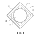
- FIG. 4 is a plan view showing the electrochemical element shown in FIG. 1 (excluding the lid material and the conductive plate).
- FIG. 5 is a plan view showing a conductive plate of the electrochemical element shown in FIG.
- FIG. 6 is a sectional view showing an electrochemical device according to the second embodiment.
- FIG. 7 is a sectional view showing an electrochemical device according to a third embodiment.
- FIG. 8 is an external perspective view showing another concave container of an electrochemical device.
- An electrochemical device includes a case including a concave container having a bottom and a side wall, a lid material covering an opening of the concave container, and a first container sealed in the case and disposed on the bottom side.
- a power generation element having an electrode layer, a second electrode layer disposed on the lid material side, and an isolation layer disposed between the first electrode layer and the second electrode layer, and disposed between the power generation element and the lid material. and a conductive plate.
- the power generation element refers to a component that can supply power to the outside through the first electrode layer and the second electrode layer.
- Examples of the power generation element include batteries such as lithium ion secondary batteries and all-solid-state batteries, as well as capacitors such as electric double layer capacitors and lithium ion capacitors.
- the first electrode layer and the second electrode layer of the power generation element are electrically isolated by the isolation layer.
- a solid electrolyte layer or a separator which is commonly used in batteries or capacitors, can be used.
- the concave container or lid of the case has a first conductive path leading from the inside to the outside corresponding to the first electrode layer, and a conductive path leading from the inside to the outside corresponding to the second electrode layer.
- the first electrode layer is electrically connected to the first conduction path.
- the second electrode layer is electrically connected to the second conduction path via the conductive plate.
- the edge of the conductive plate is fixed to the side wall of the concave container.
- the power generation element is pressed toward the bottom of the concave container by the conductive plate.
- the conductive plate presses the power generation element toward the bottom side of the concave container in this manner, the conductive plate contacts the power generation element more stably even when the volume of the power generation element changes.
- the edges of the conductive plate are fixed to the side wall of the concave container, the sealed battery can maintain good electrical connection without causing displacement of the conductive plate due to vibration etc. .
- the lid material does not come into contact with the power generating element, it is not affected by variations in the thickness of the power generating element when joining the lid material to the upper end surface of the side wall of the concave container, improving the sealing performance of the case. I can do it.
- a gap is formed between the conductive plate and the lid material.
- the lid material and the concave container may be bonded together with an adhesive, or may be fixed by welding via a seal ring.
- the lid material and the conductive plate do not come into contact with each other, there is no need to press the battery element or the conductive plate with the lid material when joining the lid material to the upper end surface of the concave container, further improving the sealing performance of the case. be able to. Further, even if the conductive plate is deformed toward the lid member due to volumetric expansion of the power generation element, the lid member is not pressed by the conductive plate, so deformation of the lid member during charging and discharging can be prevented.
- the conductive plate has an edge fixed to the side wall of the concave container, a bottom surface that faces the power generation element and has a flat surface that presses the power generation element toward the bottom of the concave container, and The step portion may be displaced in the thickness direction.
- the thickness direction of the conductive plate can also be said to be a direction perpendicular to the bottom surface.
- the edge of the conductive plate is configured to be fixed to the side wall of the concave container. By fixing the edge of the conductive plate to the side wall of the concave container, the bottom surface of the conductive plate can press the power generation element toward the bottom of the concave container. In this state, as described above, the conductive plate electrically connects the second electrode layer and the second conduction path.
- the flat bottom surface of the conductive plate presses the power generation element toward the bottom side of the concave container over a wider area, so that even if a volume change occurs in the power generation element, the conductive plate is more stable with the power generation element. come into contact with. Furthermore, damage to the electrode layer during expansion of the power generation element can be suppressed, and good electrical connection can be maintained.
- the lid material does not come into contact with the conductive plate or the power generation element, when joining the lid material to the upper end surface of the side wall of the concave container, it is possible to uniformly join the entire circumference, and the sealing of the case is improved. can be improved.
- a stepped portion displaced in the thickness direction is formed around the bottom surface of the conductive plate. This makes it easier for the conductive plate to function as a spring, making it easier for the bottom surface to press the power generation element due to its elasticity. Furthermore, the overall thickness can be made thinner than a conductive plate formed in a diaphragm shape.
- the edge of the conductive plate that is, the position of the supported portion as described later, can be freely set in the height direction (thickness direction of the conductive plate).
- the position fixed to the inner circumferential surface of the side wall of the container can be set closer to the bottom of the concave container than the bottom of the conductive plate, so even if a gap is formed between the lid and the conductive plate. Since the distance between the lid material and the bottom surface of the conductive plate does not become large, the gap between the lid material and the power generation element can be restricted, so that it can be prevented from becoming an impediment to increasing the capacity. .
- the concave container may have a plurality of support portions on the side wall portion.
- the edge of the conductive plate may have a plurality of supported parts corresponding to each supporting part.
- Each supported part may be fixed to a support part.
- the edge of the conductive plate can be fixed to the side wall of the concave container, for example, as follows.
- a support portion for locking the edge of the conductive plate is provided on the inner peripheral surface of the side wall portion of the concave container.
- a supported portion that is engaged with the supporting portion is provided at the edge of the conductive plate.
- each supported part is locked and supported by the support part, the edge of the conductive plate is fixed to the side wall part, and the bottom surface of the conductive plate presses the power generation element toward the bottom of the concave container. can do. This allows better electrical connection to be maintained.
- the support portion of the concave container may be a protrusion formed on the inner circumferential surface of the side wall portion.
- the supported portion of the conductive plate may be a locking piece that extends from the edge of the conductive plate and can be locked to the lower surface of the projecting portion.
- the isolation layer may be a solid electrolyte layer containing a sulfide-based solid electrolyte.
- the electrochemical device may further include a conductive sheet between the bottom surface of the conductive plate and the power generation element.
- An electrochemical element uses a conductive sheet such as a metal foil, a porous body, a carbon sheet or a nonwoven fabric, or a coating containing a conductive material such as metal or carbon between the bottom of the conductive plate and the power generation element.
- a conductive film such as a film or a vapor-deposited film may be arranged.
- the electrochemical element can be sealed inside the case with the power generation element enclosed in an exterior material other than the case, such as a metal container, and the power generation element can be sealed doubly by the case and the exterior material. It can also be configured with That is, the electrochemical element may be configured such that a flat element formed by enclosing a power generation element in an exterior material is sealed in a case.
- another aspect of the electrochemical device includes a case including a concave container having a bottom and a side wall, a lid material covering an opening of the concave container, and a first container sealed in the case and disposed on the bottom side.
- An exterior material including an electrode terminal and a second electrode terminal disposed on the lid material side, and an exterior material enclosed within the exterior material and between the first electrode layer, the second electrode layer, and the first electrode layer and the second electrode layer.
- the present invention includes a flat element having a power generation element including a disposed isolation layer, and a conductive plate disposed between the flat element and a lid member.
- the first electrode terminal is electrically connected to a first conduction path leading from the inside of the case to the outside.
- the second electrode terminal is electrically connected to a second conduction path leading from the inside of the case to the outside via the conductive plate.
- the edge of the conductive plate is fixed to the side wall of the concave container.
- the flat element is pressed towards the bottom of the concave container by the conductive plate.
- a gap is formed between the conductive plate and the lid material. In this way, even when a flat element is housed in the internal space of the case, good electrical connection can be maintained. .
- the conductive plate has an edge fixed to the side wall of the concave container, and a planar bottom surface that faces the flat element and presses the flat element toward the bottom of the concave container. , and a stepped portion displaced from the bottom surface in the thickness direction.
- the electrochemical element of configuration 8 can obtain the same effect as the electrochemical element of configuration 2.
- the concave container has a plurality of supports on the side wall.
- the edge of the conductive plate has a plurality of supported parts corresponding to each supporting part.
- Each supported part is fixed to the support part.
- the support portion of the concave container may be a protrusion formed on the inner circumferential surface of the side wall portion.
- the supported portion of the conductive plate may be a locking piece that extends from the edge of the conductive plate and can be locked to the lower surface of the projecting portion.
- the isolation layer is a solid electrolyte layer containing a sulfide-based solid electrolyte.
- the flat element is an all-solid-state battery.
- the electrochemical element further includes a conductive sheet between the bottom surface of the conductive plate and the flat element.
- the electrochemical element of configuration 12 can obtain the same effect as the electrochemical element of configuration 6.
- the material of the concave container is not particularly limited, and various materials such as resin, glass (borosilicate glass, glass ceramics, etc.), metal, and ceramic can be used. It may also be a composite material in which ceramic or glass powder is dispersed in a resin.
- the concave container is made of a metal material, in order to ensure insulation between the concave container and the power generation element or between the concave container and the flat element, the inner surface of the bottom of the concave container and the inner peripheral surface of the side wall are It is desirable to cover with an insulating material such as a resin material or glass.
- the electrochemical device 1 includes a case 10, a power generation element 20 housed in the case 10, and a conductive plate 30 housed in the case 10.
- the case 10 includes a concave container 11, a lid 12, an external terminal 13, and an external terminal 14.
- the concave container 11 is made of ceramic.
- the concave container 11 includes a square bottom 111 and a square cylindrical side wall 112 that is formed continuously from the outer periphery of the bottom 111 and has a cylindrical space for accommodating the power generation element 20 therein. There is.
- the side wall portion 112 is provided so as to extend substantially perpendicularly to the bottom portion 111 when viewed in longitudinal section.
- a conductor portion 113 is formed inside the bottom portion 111 .
- the conductor portion 113 extends between the power generation element 20 and the bottom portion 111 so as to be conductively connected to the power generation element 20, and forms a conduction path corresponding to the electrode layer 21.
- a conductor portion 114 is formed inside the side wall portion 112 . As shown in FIG.
- a portion of the conductor portion 114 is formed on the inner circumferential surface of the side wall portion 112 to be exposed to the lower surface and side surface of the support portion 115, which will be described later, and has a conductive path corresponding to the electrode layer 22. is formed.
- a method for manufacturing the concave container 11 will be described later.
- the concave container 11 is not limited to ceramic, and may be made of an insulating material such as synthetic resin.
- the concave container 11 is not limited to a rectangular shape in plan view, but may be circular, elliptical, or polygonal.
- the internal space for accommodating the power generation element 20 is not limited to a cylindrical shape, but may be formed in a polygonal cylinder shape such as a square cylinder shape depending on the shape of the power generation element 20.
- the conductor portion 114 may be formed on the inner surface of the side wall portion 112 instead of inside the side wall portion 112, and may further penetrate the inside of the bottom portion 111 to be electrically connected to the external terminal 14.
- an insulating layer may be formed between the outer circumferential surface of the power generating element 20 and the conductor section 114, for example, on the inner surface of the conductor section 114, so that the outer circumferential surface of the power generating element 20 and the conductor section 114 do not come into contact with each other. desirable.
- the side wall portion 112 has a plurality of support portions 115 that support the conductive plate 30.
- the support portion 115 is a projecting portion that is formed at the upper end of the inner circumferential surface of the side wall portion 112 and projects radially inward. More specifically, the support portion 115 is a top wall of a plurality of depressions formed radially outward on the inner peripheral surface of the side wall portion 112, as shown in FIG. As a result, the support portion 115 is formed to protrude radially inward.
- the lower surface of each support portion 115 that is, the lower surface of each ceiling wall, can engage and support a supported portion 31 of a conductive plate 30, which will be described later.
- supporting parts 115 are provided in this embodiment, the number is not limited. For example, when the number of supported parts 31 of the conductive plate 30 described later is two, as shown in FIG. Two supporting parts 115 may be provided at positions corresponding to the supported parts 31.
- the lid material 12 is a rectangular thin metal plate that covers the opening of the concave container 11. As shown in FIGS. 1 and 4, the lid 12 is joined to the concave container 11 by a square frame-shaped seal ring 15 disposed between the lower surface of its outer peripheral edge and the upper end of the concave container 11 (seam welding). ) has been done. Thereby, the internal space of the case 10 is completely sealed.
- the interior space of the case 10 is preferably a vacuum atmosphere or an inert gas atmosphere such as nitrogen, considering the influence on the power generation element 20. Note that the lid material 12 is not limited to a thin metal plate as long as it can cover the opening of the concave container 11.
- the lid material 12 is not limited to a rectangular shape, but can be variously changed to a circular shape, an elliptical shape, a polygonal shape, etc. depending on the shape of the concave container 11 in a plan view. Moreover, the lid material 12 may have a shape other than a flat plate. Note that the lid material 12 may be bonded to the concave container 11 with an adhesive, and the method of joining the lid material 12 and the concave container 11 is not particularly limited.
- the external terminal 13 is arranged on the outer surface of the bottom 111 of the concave container 11.
- the external terminal 13 is electrically connected to an electrode layer 21, which will be described later, via a conductor portion 113.
- the electrode layer 21 functions as a positive electrode layer as described later. Therefore, the conductor portion 113 becomes a conduction path that connects the external terminal 13 and the positive electrode layer, and the external terminal 13 functions as a positive electrode terminal.
- the external terminal 14 is arranged on the outer surface of the bottom 111 of the concave container 11 away from the external terminal 13.
- the external terminal 14 is electrically connected to a supported portion 31 of a conductive plate 30, which will be described later, via a conductor portion 114.
- the conductive plate 30 is electrically connected to the electrode layer 22 functioning as a negative electrode layer. Therefore, the conductor portion 114 becomes a conduction path that connects the external terminal 14 and the negative electrode layer, and the conductive plate 30 functions as a connection terminal that connects this conduction path and the electrode layer 22. Functions as a terminal.
- the arrangement of the external terminals 13 and 14 is not limited to the above, and may be arranged on the outer surface of the side wall portion 112 of the concave container 11, with the lid member 12 functioning as the conductor portion 114, and the external terminals 14 It is also possible to form it on the outer surface of the lid member 12. However, by arranging these terminals on the outer surface of the bottom 111 of the concave container 11 at a constant interval, mounting on the surface of the circuit board becomes easier.
- a method for manufacturing the concave container 11 will be explained.
- a printed pattern that will become the conductor portions 113 and 114 is formed by printing and coating a ceramic green sheet with a metal paste.
- a plurality of green sheets having these printed patterns formed thereon are laminated and fired.
- the above-mentioned support portion 115 is formed by stacking a plurality of green sheets having different shapes.
- this manufacturing method is not limited as long as the support portion 115 can be formed on the inner circumferential surface of the side wall portion 112.
- the external terminals 13 and 14 can also be formed by printing patterns of this metal paste.
- the power generation element 20 includes a laminate in which an electrode layer (positive electrode layer) 21, an electrode layer (negative electrode layer) 22, and a solid electrolyte layer 23 are stacked. Solid electrolyte layer 23 is arranged between electrode layer 21 and electrode layer 22 as a separation layer. That is, in this embodiment, the isolation layer is the solid electrolyte layer 23.
- the power generation element 20 is formed into a cylindrical shape.
- the power generation element 20 includes an electrode layer 21, a solid electrolyte layer 23, and an electrode layer 22 stacked in this order from the bottom 111 side (lower side in the drawing) of the concave container 11.
- the power generation element 20 is arranged such that the electrode layer 21, which is one end thereof, is on the bottom 111 side of the concave container 11, and the electrode layer 22, which is the other end, is on the lid material 12 side. They are arranged in such a manner that they become symmetrical, and are accommodated in the internal space of the case 10.
- the power generation element 20 is not limited to a cylindrical shape, and can be modified into various shapes such as a rectangular parallelepiped shape and a polygonal column shape.
- the power generation element 20 may have a plurality of laminates. The plurality of laminates may be stacked so as to be connected in series.
- the electrode layer 21 is made of a positive electrode mixture containing lithium cobalt oxide as a positive electrode active material, a sulfide-based solid electrolyte, and graphene as a conductive agent in a mass ratio of 65:30:5.
- the positive electrode pellet was placed in a 45 mm mold and molded into a cylindrical shape.
- the positive electrode active material of the electrode layer 21 is not particularly limited as long as it can function as the positive electrode layer of the power generation element 20, and examples thereof include lithium nickelate, lithium manganate, lithium nickel cobalt manganese composite oxide, It may be an olivine-type complex oxide or the like, or it may be an appropriate mixture of these. There are no particular limitations on other constituent materials or proportions.
- the size and shape of the electrode layer 231 are not limited to a cylindrical shape, and can be changed in various ways depending on the size and shape of the electrochemical element 1.
- the electrode layer 22 contains LTO (Li 4 Ti 5 O 12 , lithium titanate), a sulfide-based solid electrolyte, and graphene in a weight ratio of 50:40 as a negative electrode active material used in a lithium ion secondary battery.
- This is a negative electrode pellet formed into a cylindrical shape from a negative electrode mixture containing 10 parts.
- the negative electrode active material of the electrode layer 22 is not particularly limited as long as it can function as the negative electrode layer of the power generation element 20, and examples thereof include metallic lithium, lithium alloy, and carbon such as graphite and low crystal carbon. It may be a material, an oxide such as SiO, or a mixture of these as appropriate. There are no particular limitations on other constituent materials or proportions. Further, the size and shape of the electrode layer 22 are not limited to a cylindrical shape, and can be changed in various ways depending on the size and shape of the electrochemical element 1.
- the solid electrolyte layer 23 includes a sulfide-based solid electrolyte.
- the solid electrolyte layer 23 is formed into a cylindrical shape.
- the solid electrolyte contained in the electrode layer 21, the electrode layer 22, and the solid electrolyte layer 23 is not particularly limited, but from the viewpoint of ionic conductivity, a sulfide-based solid electrolyte, particularly an argyrodite-type sulfide-based solid electrolyte is preferable. used.
- the surface of the positive electrode active material is preferably coated with a lithium ion conductive material such as niobium oxide in order to prevent reaction with the positive electrode active material.
- the solid electrolyte included in the solid electrolyte layer 23, the electrode layer 21, and the electrode layer 22 may be a hydride solid electrolyte, an oxide solid electrolyte, or the like.
- the size and shape of the solid electrolyte layer 23 are not limited to a cylindrical shape, and can be changed in various ways depending on the size and shape of the electrochemical element 1.
- the conductive plate 30 is a metal plate having a rectangular shape in a plan view and is installed in the opening of the concave container 11 of the case 10.
- the conductive plate 30 has a plurality of supported parts 31 corresponding to the positions of the respective supporting parts 115 described above.
- the supported part 31 is the above-mentioned support part 115, that is, a hook-shaped locking piece that is locked to the lower surface of the ceiling wall. More specifically, the supported portion 31 extends from the edge of the conductive plate 30 toward the above-mentioned support portion 115 (downward in FIG. 1).
- the supported portion 31 has a supporting portion 115, that is, a tip that is folded back toward the lower surface of the ceiling wall.
- the tip of the supported portion 31 is in contact with the conductor portion 114 exposed on the lower surface and side surface of the above-mentioned ceiling wall.
- the conductive plate 30 functions as a current collector, and also functions as a connection terminal that electrically connects the electrode layer 22 and the conduction path leading to the external terminal 14.
- the conductive plate 30 is supported by a support portion 115 formed on the inner peripheral surface of the concave container 11 and covers a part of the opening of the concave container 11 .
- the area of the conductive plate 30 in plan view is smaller than the opening area of the concave container 11.
- the conductive plate 30 presses the power generation element 20 toward the bottom 111 of the concave container 11 while being fixed to the side wall 112 of the concave container 11.
- the conductive plate 30 has a recess that is recessed toward the electrode layer 22 at a position where it contacts the top surface of the electrode layer 22, which is the other end of the power generation element 20.
- the bottom surface 32 of the recess is formed into a flat surface so that the power generation element 20 can be pressed over a wider area.
- the periphery of the bottom surface 32 of the recess is a stepped portion 33 that is displaced in the thickness direction.
- the step portion 33 is a peripheral wall of a truncated cone whose diameter gradually decreases toward the power generation element 20.
- the bottom surface 32 of the recess faces the electrode layer 22 and is in contact with the top surface of the electrode layer 22.
- the flat bottom surface 32 presses the electrode layer 22 over a wide area, thereby suppressing damage to the electrode layer 22 when the power generation element 20 expands.
- good electrical connection can be maintained.
- the step portion 33 the overall thickness of the conductive plate 30 can be reduced.
- the edge of the conductive plate 30, that is, the position of the supported portion can be freely set in the height direction (thickness direction of the conductive plate), a gap is formed between the lid member 12 and the conductive plate 30. Even in this case, the distance between the lid member 12 and the bottom surface 32 of the conductive plate 30 does not become large. As a result, it is possible to suppress the gap between the lid material 12 and the power generation element 20 from increasing, so that the capacity of the electrochemical element 1 can be increased.
- the thickness direction is the vertical direction in FIG. 1 (height direction of the electrochemical element 1), and can also be said to be a direction perpendicular to the bottom surface 32 in the drawing.
- the entire bottom surface 32 does not need to be a flat surface, and a portion thereof may have a shape other than a flat surface.
- the larger the proportion of the bottom surface 32 occupied by the flat surface is, the larger the contact area with the electrode layer 22 becomes, and the contact resistance can be reduced, which is preferable, and it is more preferable that the entire bottom surface 32 is formed of a flat surface.
- Examples of metals constituting the conductive plate 30 include nickel, iron, copper, chromium, cobalt, titanium, aluminum, and alloys thereof, and in order to facilitate the function as a leaf spring, SUS301-CSP and SUS304-CSP are used. , SUS316-CSP, SUS420J2-CSP, SUS631-CSP, and SUS632J1-CSP are preferably used for springs.
- the thickness of the conductive plate 30 is preferably 0.05 mm or more, more preferably 0.07 mm or more, and 0.1 mm or more, in order to keep the pressing force on the power generation element 20 above a certain level. It is particularly preferable to do so.
- the thickness of the plate 30 is preferably 0.5 mm or less, more preferably 0.4 mm or less, and particularly preferably 0.3 mm or less.
- the area of the bottom surface of the conductive plate is preferably 10% or more, more preferably 30% or more, and 50% of the area of the electrode 22 of the opposing power generation element in plan view. It is particularly preferable to set it above, and most preferably to set it as 60% or more.
- the area of the bottom surface 32 of the conductive plate 30 should be 100% or less of the area of the electrode layer 22 in a plan view of the opposing power generation element 20. It is preferably 95% or less, more preferably 90% or less, most preferably 85% or less.
- the shape of the bottom surface 32 of the conductive plate 30 does not have to be a completely flat surface, and may have an uneven surface such as an embossed surface in order to reduce the contact resistance with the power generation element 20. good.
- the conductive plate 30 is placed on the top surface of the power generating element 20 after the power generating element 20 is accommodated inside the concave container 11.
- the tip of the supported part 31 is connected to the top surface of the power generation element 20 and the support part 115, in the axial direction of the power generation element 20 (vertical direction in FIG. 1) In other words, it is positioned between it and the lower surface of the ceiling wall.
- the supported portion 31 is supported by the supporting portion 115. More specifically, the tip of the supported portion 31 is locked to the support portion 115, that is, the lower surface of the ceiling wall.
- the conductive plate 30 Since the supported portion 31 is pushed downward, the conductive plate 30 is bent in the opposite direction to the electrode layer 22 while in contact with the power generation element 20 .
- the conductive plate 30 presses the power generation element 20 toward the bottom 111 of the concave container 11 by its elastic force. Thereby, the conductive plate 30 can contact the power generation element 20 more stably without being displaced due to vibration or the like, and can maintain a good electrical connection without being displaced due to vibration or the like.
- the influence of bending on the planar bottom surface 32 is reduced, so that electrical connection can be maintained better. In this way, if the conductive plate 30 can press the power generation element 20 toward the bottom 111 of the concave container 11 by its elastic force with the edge supported by the inner circumferential surface of the side wall 112, then Its configuration is not particularly limited.
- a gap is formed between the conductive plate 30 and the lid material 12. That is, the conductive plate 30 and the lid member 12 do not come into contact with each other. Thereby, even if the conductive plate 30 is pushed toward the lid 12 due to a change in the volume of the power generation element 20, deformation of the lid 12 can be suppressed. Further, the lid member 12 and the concave container 11 are welded together via the seal ring 15 as described above. By providing a gap between the conductive plate 30 and the lid member 12, the influence of welding heat on the power generation element 20 can be suppressed.
- the conductive plate 30 and the lid 12 do not come into contact with each other, when the lid 12 is joined to the upper end surface of the side wall 112 of the concave container 11, it is not affected by the volume change of the power generation element 20, and the case 10 is sealed. The stopping performance can be further improved.
- the electrochemical device 1 of this embodiment has a conductive sheet 40 between the electrode layer 22 and the conductive plate 30.
- the conductive sheet 40 is a conductive carbon sheet made of expanded graphite, that is, a graphite sheet.
- a graphite sheet is manufactured as follows. First, acid-treated graphite particles, which are natural graphite treated with an acid, are heated. Then, the acid-treated graphite expands as the acid between its layers evaporates and foams. This expanded graphite (expanded graphite) is molded into a felt shape, and further rolled using a roll mill to form a sheet body.
- the conductive sheet 40 is manufactured by hollowing out the expanded graphite sheet into a circular shape.
- expanded graphite is formed by vaporizing acid and foaming acid-treated graphite. Therefore, the graphite sheet is formed into a porous shape. Therefore, the graphite sheet has not only the electrical conductivity of graphite itself, but also flexibility that conventional graphite products do not have.
- the method for producing the graphite sheet is not limited to this, and the graphite sheet may be made of a material other than expanded graphite, and the graphite sheet may be produced by any method.
- the apparent density of the graphite sheet is preferably 0.3 g/cm 3 or more, more preferably 0.7 g/cm 3 or more, and preferably 1.5 g/cm 3 or less, more preferably 1.3 g/cm 3 or less. It is better to This is because if the apparent density of the graphite sheet is too low, the graphite sheet will be easily damaged, and if the apparent density is too high, the flexibility will decrease. Note that the apparent density is not limited to the graphite sheet, and can also be applied to the conductive sheet 40 formed of other materials such as conductive tape.
- the thickness of the graphite sheet is preferably 0.05 mm or more, more preferably 0.07 mm or more, preferably 0.5 mm or less, and more preferably 0.2 mm or less. If the thickness of the graphite sheet is too small, the graphite sheet will be easily damaged, and if the thickness is too large, the graphite sheet will narrow the internal space of the case 10 that accommodates the power generation element 20, reducing the volume (thickness) of the power generation element 20 that can be accommodated. This is to do so. Note that the thickness of the graphite sheet is not limited to that of the graphite sheet, and the conductive sheet 40 formed of other materials such as conductive tape and metal can also be used.
- the conductive sheet 40 that is more flexible than the conductive plate, that is, easily deformable, the pressing force of the conductive plate 30 described above is more uniformly transmitted to the power generation element 20, thereby preventing damage to the power generation element 20.
- the conductive sheet 40 may be placed between the electrode layer 21 and the bottom 111 of the concave container 11, as shown in FIG. Thereby, it is possible to further suppress damage to the power generation element 20 and stabilize the electrical connection.
- the electrochemical device 1 of the third embodiment will be specifically described using FIG. 7.
- the explanation of the same configuration as the electrochemical device 1 of the first embodiment and the second embodiment is basically omitted, and the electrochemical device 1 of the first embodiment and the second embodiment is Only the configuration different from that of element 1 will be explained.
- the electrochemical device 1 of this embodiment accommodates a flat element 50 in the internal space of the case 10.
- the flat element 50 includes an outer can (electrode terminal) 51, a sealing can (electrode terminal) 52, the above-described power generation element 20, and a gasket 53.
- the outer can 51 includes a circular flat part 511 and a cylindrical side wall part 512 that is continuously formed from the outer periphery of the flat part 511.
- the cylindrical side wall portion 512 is provided so as to extend substantially perpendicularly to the flat portion 511 when viewed in longitudinal section.
- the outer can 51 is made of a metal material such as stainless steel.
- the outer can 51 is arranged on the bottom 111 side of the concave container 11.
- the sealing can 52 includes a circular flat part 521 and a cylindrical peripheral wall part 522 that is continuously formed from the outer periphery of the flat part 521.
- the opening of the sealed can 52 faces the opening of the outer can 51.
- the sealing can 52 is made of a metal material such as stainless steel.
- the sealing can 52 is arranged on the lid material 12 side.
- the power generation element 20 is housed between the outer can 51 and the sealed can 52. Therefore, the outer can 51 functions as an electrode terminal connected to the conductor portion 113, and the sealed can 52 functions as the other electrode terminal connected to the conductive plate 30.
- the outer can 51 and the sealing can 52 are caulked with a gasket 53 between the cylindrical side wall 512 of the outer can 51 and the peripheral wall 522 of the sealing can 52 after the power generation element 20 is housed in the internal space.
- the outer can 51 and the sealing can 52 are configured such that the openings of the outer can 51 and the sealing can 52 face each other, and the peripheral wall portion 522 of the sealing can 52 is placed inside the cylindrical side wall portion 512 of the outer can 51.
- the gasket 53 is crimped between the cylindrical side wall portion 512 and the peripheral wall portion 522.
- the exterior can 51 and the sealing can 52 are not limited to a circular shape in plan view, but can be changed into various shapes such as an elliptical shape or a polygonal shape.
- the gasket 53 is made of a resin material such as polyamide resin, polypropylene resin, or polyphenylene sulfide resin.
- the method for sealing the internal space formed by the outer can 51 and the sealing can 52 is not limited to caulking via the gasket 53, and may be performed by other methods.
- the cylindrical side wall portion 512 of the outer can 51 and the peripheral wall portion 522 of the sealing can 52 may be joined with a hot melt resin, an adhesive, or the like interposed therebetween, and sealed.
- the conductive plate 30 is placed on the upper surface of the flat element 50, and the supported part 31 is latched to and supported by the support part 115. At this time, the conductive plate 30 is bent in the opposite direction to the flat element 50 while being in contact with the flat part 521 of the sealed can 52 .
- the conductive plate 30 presses the flat element 50 toward the bottom 111 of the concave container 11 by its elastic force. As a result, the conductive plate 30 is in more stable contact with the flat element 50 without being displaced due to vibrations or the like, and similarly to the electrochemical element 1 of the first embodiment described above, the conductive plate 30 is prevented from being displaced due to vibrations or the like. A good electrical connection can be maintained without any occurrence.
- the above-mentioned conductive sheet 40 or conductive film may be arranged between the flat element 50 and the conductive plate 30. Furthermore, a conductive sheet 40 or a conductive film may be arranged between the flat element 0 and the bottom 111 of the concave container 11.
- the flat element 50 is not limited to an all-solid battery having a solid electrolyte layer, but may also be a non-aqueous electrolyte battery such as a lithium ion secondary battery, another flat battery, or a capacitor such as a lithium ion capacitor. There may be.
- the support portion 115 is formed to protrude inward in the radial direction, but as shown in FIG. It may be formed so as to protrude along the circumferential direction of the inner circumferential surface of 112. That is, the support portion 115 may be a ceiling wall formed radially outward on the inner circumferential surface of the side wall portion 112.
- the top wall has an opening through which the supported portion (locking piece) 31 of the conductive plate 30 is inserted from the upper end surface of the concave container 11 .
- the supported portion 31 is inserted into the recess through an opening in the top wall.
- the folded end of the supported portion 31 comes into contact with the lower surface of the top plate.
- the supported portion 31 can also be supported by the support portion 115 in this manner.
- the orientation of the supported portion 31 of the conductive plate 30 may be changed so that it can be locked to the support portion 115 that extends in the circumferential direction.
- the angle of the supported portion 31 shown in FIG. 5 in plan view may be displaced by 90 degrees.
- the number of support parts 115 may be two or more.
- the supported parts 31 may be formed according to the number of supporting parts 115.
- the support portion 115 may be provided not on the inner peripheral surface of the side wall portion 112 but on the upper end surface of the side wall portion 112.
- the support portion 115 may be a protruding portion that protrudes radially inward in a recess having an opening on the upper end surface of the side wall portion 112.
- the conductive plate 30 can be fixed such that the supported part 31 is inserted into a recess provided in the upper end surface of the side wall part 112.
- the tip of the supported portion 31 may be supported by the lower surface of a supporting portion 115 (projecting portion) projecting inward in the radial direction or in the circumferential direction.
- the conductive plate 30 may be fixed by press-contacting the supported portion 31. As described above, if the conductive plate 30 can press the power generation element 20 toward the bottom 111 of the concave container 11 by its elastic force with its edge fixed to the side wall 112, the configuration is as follows. It is not particularly limited.
- the electrode layer 21 functions as a positive electrode layer and the electrode layer 22 functions as a negative electrode layer, but the electrode layer 21 functions as a negative electrode layer and the electrode layer 22 functions as a negative electrode layer. You can make it work.
- the external terminal 13 functions as a negative terminal, and the external terminal 14 functions as a positive terminal.
- the flat element 50 is housed in the internal space of the case 10 such that the outer can 51 is placed on the bottom 111 side of the concave container 11, but the sealed can 52 is placed on the bottom side of the concave container 11. It may be housed so as to be placed on the 111 side. That is, the flat element 50 may be housed in the internal space of the case 10 with the flat element 50 shown in FIG. 6 turned upside down.
- the power generation element 20 is composed of a laminate in which the electrode layer 21, the electrode layer 22, and the solid electrolyte layer 23 are laminated.
- the electrochemical element can be used as a lithium ion secondary battery, a lithium ion capacitor, an electric double layer capacitor, etc. Can be done.
- the separator and electrolyte are those commonly used in lithium ion secondary batteries, lithium ion capacitors, electric double layer capacitors, and the like.
- the electrode layer 21 and the electrode layer 22 may be replaced with a mixture layer of a positive electrode and a negative electrode that are commonly used in various electrochemical devices 1.
- An electrochemical device (all-solid-state battery) shown in FIG. 1 was fabricated using a conductive plate made of SUS304-CSP with a thickness of 0.1 mm.
- the electrochemical device of this example was subjected to a vibration test as follows to evaluate its vibration resistance.
- the sine wave sweep was a logarithmic sweep that reciprocated in the range of 7 Hz to 200 Hz in 15 minutes while changing the frequency, and the sweep was repeated 12 times in each of the three directions. Note that between 7Hz and 18Hz, the sweep is performed so that the peak acceleration is maintained at 1G, and from 18Hz, the sweep is performed until the peak acceleration reaches 8G (approximately 50Hz) while maintaining the total amplitude at 0.8mm. Furthermore, a sweep was performed so that the peak acceleration was maintained at 1 G up to 200 Hz.
- the AC impedance at 1 kHz with an applied voltage of 10 mV was measured for the electrochemical element of the example subjected to the vibration test, and compared with the AC impedance value measured before the vibration test, but no change was observed, and a concave shape was observed. It was confirmed that the electrical connection was maintained well by the conductive plate attached to the side wall of the container.
- an electrochemical device as a comparative example was produced. The same evaluation as in the above-mentioned example was performed, but in the electrochemical device of the comparative example, an increase in impedance (60% or more) was observed after the vibration test, and electrical connection could not be maintained well.
- Electrochemical element 10 Case, 11 Concave container, 12 Lid, 13 External terminal, 14 External terminal, 15 Seal ring, 111 Bottom, 112 Side wall, 113 Conductor, 114 Conductor, 115 Support, 20 Power generation element , 30 conductive plate, 31 supported part, 32 recessed part, 33 stepped part, 40 conductive sheet, 50 flat element, 51 outer can, 511 flat part, 52 sealing can, 521 flat part, 53 gasket
Abstract
Provided is an electrochemical element capable of maintaining favorable electrical connection and having excellent sealing properties. The electrochemical element 1 comprises: a case 10 having a recessed container 11 and a lid 12; a power generation element 20 sealed inside the case 10 and having an electrode layer 21, an electrode layer 22, and a separation layer 23; and a conductive plate 30 disposed between the power generation element 20 and the lid 12. The electrode layer 21 is electrically connected to a conductive path (conductor part 113) which leads to the outside. The electrode layer 22 is electrically connected to a conductive path (conductor part 114) which leads to the outside via the conductive plate 30. The conductive plate 30 is fixed to a side wall section 112 of the recessed container 11 at the edge end thereof. The power generation element 20 is pressed towards a bottom section 11 of the recessed container 11 by the conductive plate 30. A gap is formed between the conductive plate 30 and the lid 12.
Description
本開示は、ケース内に発電要素を封止した電気化学素子に関する。
The present disclosure relates to an electrochemical device in which a power generation element is sealed within a case.
従来、凹状容器及び凹状容器の開口を覆う蓋材によって形成された内部空間に発電要素が収容された電池が種々開示されている。
Conventionally, various batteries have been disclosed in which a power generation element is housed in an internal space formed by a concave container and a lid material covering the opening of the concave container.
特開2012-69508号公報(特許文献1)は、電気化学特性が安定した電気化学セルを開示している。電気化学セルは、密封容器を有する。密封容器は、ベース部材とリッド部材とからなる。両部材の間には電気化学素子が収納される収納空間が形成されている。リッド部材と電気化学素子との間には、電気化学素子を押圧する弾性部材が配設されている。特許文献1は、弾性部材として断面視においてV字形に屈曲した板バネ、又は、中央部から外周縁部に向かうにしたがって反った凹曲面状に形成されたダイヤフラム状バネを開示している。
JP 2012-69508A (Patent Document 1) discloses an electrochemical cell with stable electrochemical properties. An electrochemical cell has a sealed container. The sealed container consists of a base member and a lid member. A storage space in which an electrochemical element is stored is formed between both members. An elastic member that presses the electrochemical element is disposed between the lid member and the electrochemical element. Patent Document 1 discloses, as an elastic member, a plate spring bent in a V-shape in cross-sectional view, or a diaphragm-shaped spring formed in a concave curved shape that is warped from the center toward the outer peripheral edge.
また、特開2006-12792号公報(特許文献2)は、電池用ケースを開示している。電池用ケースは、上面の中央部に凹部が形成されたセラミックスから成る基体と、前記凹部を覆うようにして接合される蓋体とを具備する。電池用ケースは、その内部に電池要素を収容する。電池用ケースの蓋体は、中央部に全体が前記凹部側に突出した突出部が設けられているとともに、突出部の周囲の基体に接合される外周部との間に湾曲部が設けられており、電池要素を上方から押さえて固定させることができる。
Furthermore, Japanese Patent Application Publication No. 2006-12792 (Patent Document 2) discloses a battery case. The battery case includes a base made of ceramics having a recess formed in the center of its upper surface, and a lid joined to cover the recess. The battery case houses a battery element therein. The lid of the battery case is provided with a protruding part in the center thereof that projects entirely toward the recess, and a curved part is provided between the protruding part and the outer peripheral part that is joined to the base body around the protruding part. The battery element can be pressed and fixed from above.
また、国際公開第2022/030424号(特許文献3)は、電池用パッケージ及び電池モジュールを開示している。電池用パッケージは、第1面の中央部に凹部が形成されたセラミックスから成る絶縁基板と、前記第1面において凹部を囲む枠部と、前記枠部を塞ぐ蓋体とを具備する。電池用パッケージと、その内部に収容された電池により電池モジュールが構成される。電池用パッケージの蓋体と電池との間には、電池を押圧しながら電池と電気的な接続を維持する金属製の導電性シートが配置される。導電性シートは、導電性接着剤などで構成された導電性接合材を介して、第1面上に設けられた第2電極と接合されており、外部端子である第2外部電極と電池の一方の電極とが電気的に接続されている。
Furthermore, International Publication No. 2022/030424 (Patent Document 3) discloses a battery package and a battery module. The battery package includes an insulating substrate made of ceramics with a recess formed in the center of a first surface, a frame surrounding the recess on the first surface, and a lid that closes the frame. A battery module is composed of a battery package and a battery housed inside the battery package. A metal conductive sheet is placed between the lid of the battery package and the battery to maintain electrical connection with the battery while pressing the battery. The conductive sheet is bonded to a second electrode provided on the first surface via a conductive bonding material made of a conductive adhesive or the like, and the second external electrode, which is an external terminal, is connected to the battery. One electrode is electrically connected.
しかしながら、特許文献1の電気化学セルにおけるV字形に屈曲した板バネは、電気化学素子との接触が安定せず、振動等により位置ズレするおそれがある。また、凹曲面状に形成されたダイヤフラム状バネも、振動等による位置ズレのおそれがある他、電気化学素子に接触する中央部の面積が小さくなるため、電気的接続が安定しないおそれがある。
However, the V-shaped plate spring in the electrochemical cell of Patent Document 1 does not have stable contact with the electrochemical element, and may be displaced due to vibration or the like. Further, a diaphragm spring formed in a concave curved surface may also be misaligned due to vibration, etc., and the area of the central portion that contacts the electrochemical element may become smaller, so that the electrical connection may not be stable.
また、特許文献2の電池用ケースでは、基体に蓋体を接合する際に、蓋体に当接させる電池要素を蓋体で押圧しながら接合する必要があり、全周にわたって均一な接合を行うことが難しく、接合が不十分となる箇所が生じ、封止性が低下するおそれが生じる。さらに、充放電に伴う電池要素の体積変化の影響により、蓋体が変形するおそれもある。
In addition, in the battery case of Patent Document 2, when joining the lid to the base, it is necessary to press the battery element that is brought into contact with the lid with the lid, thereby achieving uniform joining over the entire circumference. This may lead to insufficient bonding at some points, leading to a risk of deterioration in sealing performance. Furthermore, there is a possibility that the lid body may be deformed due to the influence of volume change of the battery element accompanying charging and discharging.
また、特許文献3の電池モジュールでは、導電性接合材としてはんだや導電性接着剤が例示されるが、はんだを用いる場合には、はんだ付けの工程が必要になるほか、導電性シートと第2電極との間に存在させるはんだの量をコントロールするのが困難であり、接合が不十分になったり、導電性シートの平坦面と電池の平坦面とが完全に密着しないなどにより、電気抵抗が大きくなるおそれを生じる。また、導電性接着剤を用いる場合、導電性を高めようとすると接合強度が弱くなり、振動や電池の体積変化により接合状態が変化し、電気抵抗の増加などの課題を生じるおそれがある。
Further, in the battery module of Patent Document 3, solder and conductive adhesive are exemplified as the conductive bonding material, but when using solder, a soldering process is required, and the conductive sheet and the second It is difficult to control the amount of solder that is present between the electrodes, resulting in insufficient bonding, or the flat surface of the conductive sheet and the flat surface of the battery not coming into perfect contact, resulting in increased electrical resistance. There is a risk that it will become larger. Further, when using a conductive adhesive, if an attempt is made to increase the conductivity, the bonding strength becomes weaker, and the bonding state changes due to vibration or changes in the volume of the battery, which may cause problems such as an increase in electrical resistance.
そこで、本開示は、良好な電気的接続を維持することができ、かつ、封止性に優れた電気化学素子を提供することを課題とする。
Therefore, an object of the present disclosure is to provide an electrochemical element that can maintain good electrical connection and has excellent sealing properties.
上記課題を解決するために、本開示は次のように構成した。すなわち、本開示に係る電気化学素子は、底部及び側壁部を有する凹状容器と凹状容器の開口を覆う蓋材とを有するケースと、ケース内に封止され、底部側に配置された第1電極層と蓋材側に配置された第2電極層と第1電極層及び第2電極層の間に配置された隔離層とを有する発電要素と、発電要素と前記蓋材との間に配置された導電板とを備える。ケースの凹状容器又は蓋材は、第1電極層に対応して内部から外部に通じる第1導通経路と、第2電極層に対応して内部から外部に通じる導通経路を有している。第1電極層は、第1導通経路と電気的に接続されている。第2電極層は、導電板を介して第2導通経路と電気的に接続されている。導電板は、その縁端が凹状容器の側壁部に固定されている。発電要素は、導電板によって前記凹状容器の底部方向へと押圧される。
In order to solve the above problems, the present disclosure is configured as follows. That is, the electrochemical device according to the present disclosure includes a case including a concave container having a bottom and a side wall, a lid material covering an opening of the concave container, and a first electrode sealed in the case and disposed on the bottom side. a power generation element having a second electrode layer disposed on the lid material side, and an isolation layer disposed between the first electrode layer and the second electrode layer; and a power generation element disposed between the power generation element and the lid material. and a conductive plate. The concave container or lid of the case has a first conduction path leading from the inside to the outside, corresponding to the first electrode layer, and a conduction path leading from the inside to the outside, corresponding to the second electrode layer. The first electrode layer is electrically connected to the first conduction path. The second electrode layer is electrically connected to the second conduction path via the conductive plate. The conductive plate has its edge fixed to the side wall of the concave container. The power generation element is pressed toward the bottom of the concave container by the conductive plate.
本開示に係る電気化学素子によれば、良好な電気的接続を維持することができ、かつ、優れた封止性を実現することができる。
According to the electrochemical device according to the present disclosure, good electrical connection can be maintained and excellent sealing performance can be achieved.
(構成1)
本開示の実施形態に係る電気化学素子は、底部及び側壁部を有する凹状容器と凹状容器の開口を覆う蓋材とを有するケースと、ケース内に封止され、底部側に配置された第1電極層と蓋材側に配置された第2電極層と第1電極層及び第2電極層の間に配置された隔離層とを有する発電要素と、発電要素と前記蓋材との間に配置された導電板とを備える。 (Configuration 1)
An electrochemical device according to an embodiment of the present disclosure includes a case including a concave container having a bottom and a side wall, a lid material covering an opening of the concave container, and a first container sealed in the case and disposed on the bottom side. A power generation element having an electrode layer, a second electrode layer disposed on the lid material side, and an isolation layer disposed between the first electrode layer and the second electrode layer, and disposed between the power generation element and the lid material. and a conductive plate.
ここで、発電要素は、第1電極層及び第2電極層により電力を外部に供給可能な構成要素を言う。発電要素としては、リチウムイオン二次電池又は全固体電池等の電池のほか、電気二重層キャパシタ又はリチウムイオンキャパシタ等のキャパシタ等が例示される。
Here, the power generation element refers to a component that can supply power to the outside through the first electrode layer and the second electrode layer. Examples of the power generation element include batteries such as lithium ion secondary batteries and all-solid-state batteries, as well as capacitors such as electric double layer capacitors and lithium ion capacitors.
発電要素の第1電極層と第2電極層とは、隔離層により電気的に隔離される。隔離層としては、通常電池又はキャパシタで使用される固体電解質層又はセパレータを用いることができる。
The first electrode layer and the second electrode layer of the power generation element are electrically isolated by the isolation layer. As the separating layer, a solid electrolyte layer or a separator, which is commonly used in batteries or capacitors, can be used.
ケースの凹状容器又は蓋材は、第1電極層に対応して内部から外部に通じる第1導通経路と、第2電極層に対応して内部から外部に通じる導通経路を有している。第1電極層は、第1導通経路と電気的に接続されている。第2電極層は、導電板を介して第2導通経路と電気的に接続されている。
The concave container or lid of the case has a first conductive path leading from the inside to the outside corresponding to the first electrode layer, and a conductive path leading from the inside to the outside corresponding to the second electrode layer. The first electrode layer is electrically connected to the first conduction path. The second electrode layer is electrically connected to the second conduction path via the conductive plate.
また、導電板は、その縁端が凹状容器の側壁部に固定されている。発電要素は、導電板によって前記凹状容器の底部方向へと押圧される。
Furthermore, the edge of the conductive plate is fixed to the side wall of the concave container. The power generation element is pressed toward the bottom of the concave container by the conductive plate.
このように導電板が発電要素を凹状容器の底部側へと押圧することにより、導電板が発電要素の体積変化によっても発電要素とより安定的に接触する。また、導電板の縁端が凹状容器の側壁部に固定されていることにより、密閉型電池は、振動等により導電板に位置ズレが生じることなく、良好な電気的接続を維持させることができる。また、蓋材が発電要素と当接しないため、凹状容器の側壁部の上端面に蓋材を接合する際に発電要素の厚みのばらつきの影響を受けなくなり、ケースの封止性を向上させることができる。
As the conductive plate presses the power generation element toward the bottom side of the concave container in this manner, the conductive plate contacts the power generation element more stably even when the volume of the power generation element changes. In addition, since the edges of the conductive plate are fixed to the side wall of the concave container, the sealed battery can maintain good electrical connection without causing displacement of the conductive plate due to vibration etc. . In addition, since the lid material does not come into contact with the power generating element, it is not affected by variations in the thickness of the power generating element when joining the lid material to the upper end surface of the side wall of the concave container, improving the sealing performance of the case. I can do it.
さらに、導電板と蓋材との間には隙間が形成されている。これにより、発電要素の体積変化によって導電板が蓋材側へと押された場合であっても、導電板が蓋材に接触することがなく、蓋材の変形を抑制することができる。また、蓋材と凹状容器とは、接着剤により接着されてもよく、シールリングを介して溶接して固定されるのであってもよい。蓋材と導電板との間に隙間を設けたことにより、蓋材と凹状容器とを溶接する場合には、この溶接熱の発電要素への影響を抑制することができる。さらに、蓋材と導電板とが接触しないため、凹状容器の上端面に蓋材を接合する際に電池要素や導電板を蓋材で押圧する必要がなくなり、ケースの封止性をより向上させることができる。また、発電要素の体積膨張により導電板が蓋材側に変形しても蓋材が導電板によって押圧されないため、充放電時の蓋材の変形を防ぐこともできる。
Furthermore, a gap is formed between the conductive plate and the lid material. Thereby, even if the conductive plate is pushed toward the lid due to a change in the volume of the power generation element, the conductive plate does not come into contact with the lid, and deformation of the lid can be suppressed. Further, the lid material and the concave container may be bonded together with an adhesive, or may be fixed by welding via a seal ring. By providing a gap between the lid material and the conductive plate, when welding the lid material and the concave container, it is possible to suppress the influence of this welding heat on the power generation element. Furthermore, since the lid material and the conductive plate do not come into contact with each other, there is no need to press the battery element or the conductive plate with the lid material when joining the lid material to the upper end surface of the concave container, further improving the sealing performance of the case. be able to. Further, even if the conductive plate is deformed toward the lid member due to volumetric expansion of the power generation element, the lid member is not pressed by the conductive plate, so deformation of the lid member during charging and discharging can be prevented.
(構成2)
構成1の電気化学素子において、導電板は、凹状容器の側壁部に固定される縁端と、発電要素に対向し、発電要素を凹状容器の底部方向へ押圧する平面を有する底面と、底面から厚み方向に変位した段部とを有してよい。導電板の厚み方向とは、底面に対して直交する方向とも言える。導電板の縁端は、凹状容器の側壁部に固定することができるよう構成されている。導電板の縁端が凹状容器の側壁部に固定されることにより、導電板の底面は、発電要素を凹状容器の底部方向へ押圧することができる。この状態において、上述のように、導電板は、第2電極層と、第2導通経路とを電気的に接続している。 (Configuration 2)
In the electrochemical element ofConfiguration 1, the conductive plate has an edge fixed to the side wall of the concave container, a bottom surface that faces the power generation element and has a flat surface that presses the power generation element toward the bottom of the concave container, and The step portion may be displaced in the thickness direction. The thickness direction of the conductive plate can also be said to be a direction perpendicular to the bottom surface. The edge of the conductive plate is configured to be fixed to the side wall of the concave container. By fixing the edge of the conductive plate to the side wall of the concave container, the bottom surface of the conductive plate can press the power generation element toward the bottom of the concave container. In this state, as described above, the conductive plate electrically connects the second electrode layer and the second conduction path.
構成1の電気化学素子において、導電板は、凹状容器の側壁部に固定される縁端と、発電要素に対向し、発電要素を凹状容器の底部方向へ押圧する平面を有する底面と、底面から厚み方向に変位した段部とを有してよい。導電板の厚み方向とは、底面に対して直交する方向とも言える。導電板の縁端は、凹状容器の側壁部に固定することができるよう構成されている。導電板の縁端が凹状容器の側壁部に固定されることにより、導電板の底面は、発電要素を凹状容器の底部方向へ押圧することができる。この状態において、上述のように、導電板は、第2電極層と、第2導通経路とを電気的に接続している。 (Configuration 2)
In the electrochemical element of
ここで、導電板の平面を有する底面が、発電要素をより広い面積で凹状容器の底部側へと押圧することにより、発電要素に体積変化が生じても、導電板が発電要素とより安定的に接触する。また、発電要素の膨張時における電極層の破損を抑制することができ、良好な電気的接続を維持することができる。また、蓋材が導電板や発電要素と当接しないため、凹状容器の側壁部の上端面に蓋材を接合する際に、全周にわたって均一な接合を行うことができ、ケースの封止性を向上させることができる。
Here, the flat bottom surface of the conductive plate presses the power generation element toward the bottom side of the concave container over a wider area, so that even if a volume change occurs in the power generation element, the conductive plate is more stable with the power generation element. come into contact with. Furthermore, damage to the electrode layer during expansion of the power generation element can be suppressed, and good electrical connection can be maintained. In addition, since the lid material does not come into contact with the conductive plate or the power generation element, when joining the lid material to the upper end surface of the side wall of the concave container, it is possible to uniformly join the entire circumference, and the sealing of the case is improved. can be improved.
導電板の底面の周囲には、厚み方向に変位した段部が形成されている。これにより、導電板がバネとして機能しやすくなり、弾性により前記底面が発電要素を押圧しやすくなる。また、ダイヤフラム状に形成された導電板に比べ、全体の厚みを薄くすることができる。また、導電板の縁端、すなわち、後述するような被支持部の位置は、高さ方向(導電板の厚み方向)に自由に設定することができ、例えば、導電板の縁端における、凹状容器の側壁部の内周面に固定される位置を、導電板の底面よりも凹状容器の底部に近い位置とすることもできるので、蓋材と導電板との間に隙間を形成した場合でも、蓋材と導電板の底面との距離が大きくならず、従って、蓋材と発電要素との間の空隙を制限することができるので、高容量化の阻害要因となることを防ぐことができる。
A stepped portion displaced in the thickness direction is formed around the bottom surface of the conductive plate. This makes it easier for the conductive plate to function as a spring, making it easier for the bottom surface to press the power generation element due to its elasticity. Furthermore, the overall thickness can be made thinner than a conductive plate formed in a diaphragm shape. In addition, the edge of the conductive plate, that is, the position of the supported portion as described later, can be freely set in the height direction (thickness direction of the conductive plate). The position fixed to the inner circumferential surface of the side wall of the container can be set closer to the bottom of the concave container than the bottom of the conductive plate, so even if a gap is formed between the lid and the conductive plate. Since the distance between the lid material and the bottom surface of the conductive plate does not become large, the gap between the lid material and the power generation element can be restricted, so that it can be prevented from becoming an impediment to increasing the capacity. .
(構成3)
構成1又は2の電気化学素子において、凹状容器は、側壁部に複数の支持部を有してよい。導電板の縁端は、各々の支持部に対応する複数の被支持部を有してよい。各々の被支持部は、支持部に固定されてよい。 (Configuration 3)
In the electrochemical device of configuration 1 or 2, the concave container may have a plurality of support portions on the side wall portion. The edge of the conductive plate may have a plurality of supported parts corresponding to each supporting part. Each supported part may be fixed to a support part.
構成1又は2の電気化学素子において、凹状容器は、側壁部に複数の支持部を有してよい。導電板の縁端は、各々の支持部に対応する複数の被支持部を有してよい。各々の被支持部は、支持部に固定されてよい。 (Configuration 3)
In the electrochemical device of
導電板の縁端は、例えば以下のようにして、凹状容器の側壁部に固定することができる。凹状容器の側壁部の内周面には、導電板の縁端を係止させるための支持部が設けられる。また、導電板の端縁には、支持部に係止させる被支持部が設けられる。導電板を確実に固定するために、凹状容器の側壁部の内周面には、支持部を複数設けることが好ましく、導電板の端縁には、各々の支持部の位置に対応する複数の被支持部を設けることが好ましい。各々の被支持部が支持部に係止されて支持されることにより、導電板の縁端は、側壁部に固定されるとともに、導電板の底面は、発電要素を凹状容器の底部方向へ押圧することができる。これにより、より良好な電気的接続を維持することができる。
The edge of the conductive plate can be fixed to the side wall of the concave container, for example, as follows. A support portion for locking the edge of the conductive plate is provided on the inner peripheral surface of the side wall portion of the concave container. Furthermore, a supported portion that is engaged with the supporting portion is provided at the edge of the conductive plate. In order to securely fix the conductive plate, it is preferable to provide a plurality of supports on the inner peripheral surface of the side wall of the concave container, and the edge of the conductive plate has a plurality of supports corresponding to the positions of the respective supports. It is preferable to provide a supported portion. Since each supported part is locked and supported by the support part, the edge of the conductive plate is fixed to the side wall part, and the bottom surface of the conductive plate presses the power generation element toward the bottom of the concave container. can do. This allows better electrical connection to be maintained.
(構成4)
構成3の電気化学素子において、凹状容器の支持部は、側壁部の内周面に形成された張出部とすることができる。導電板の被支持部は、導電板の縁端から延びて張出部の下面に係止可能な係止片とすることができる。 (Configuration 4)
In the electrochemical element of configuration 3, the support portion of the concave container may be a protrusion formed on the inner circumferential surface of the side wall portion. The supported portion of the conductive plate may be a locking piece that extends from the edge of the conductive plate and can be locked to the lower surface of the projecting portion.
(構成5)
構成1~4のいずれかの電気化学素子において、隔離層は、硫化物系固体電解質を有する固体電解質層であってよい。 (Configuration 5)
In the electrochemical device of any ofStructures 1 to 4, the isolation layer may be a solid electrolyte layer containing a sulfide-based solid electrolyte.
構成1~4のいずれかの電気化学素子において、隔離層は、硫化物系固体電解質を有する固体電解質層であってよい。 (Configuration 5)
In the electrochemical device of any of
(構成6)
構成1~5のいずれかの電気化学素子において、電気化学素子は、導電板の底面と発電要素との間に、導電シートをさらに有してよい。電気化学素子は、導電板の底面と発電要素との間に、例えば、金属製の箔や多孔体、或いはカーボン製のシートや不織布などの導電シートや、金属やカーボンなどの導電材料を含む塗膜や蒸着膜等の導電膜を配置してもよい。これにより、導電板と発電要素とを直接接触させる場合に比べ、接触抵抗を低減することができ、より一層良好な電気的接続を実現することができる。なお、接触抵抗を低減しやすくするために、導電シートや導電膜は、導電板に比べて変形しやすい柔軟性の高いものを用いることが好ましい。 (Configuration 6)
In the electrochemical device according to any one ofconfigurations 1 to 5, the electrochemical device may further include a conductive sheet between the bottom surface of the conductive plate and the power generation element. An electrochemical element uses a conductive sheet such as a metal foil, a porous body, a carbon sheet or a nonwoven fabric, or a coating containing a conductive material such as metal or carbon between the bottom of the conductive plate and the power generation element. A conductive film such as a film or a vapor-deposited film may be arranged. Thereby, contact resistance can be reduced compared to the case where the conductive plate and the power generation element are brought into direct contact with each other, and an even better electrical connection can be achieved. Note that, in order to easily reduce contact resistance, it is preferable to use a conductive sheet or a conductive film that has high flexibility and is easier to deform than a conductive plate.
構成1~5のいずれかの電気化学素子において、電気化学素子は、導電板の底面と発電要素との間に、導電シートをさらに有してよい。電気化学素子は、導電板の底面と発電要素との間に、例えば、金属製の箔や多孔体、或いはカーボン製のシートや不織布などの導電シートや、金属やカーボンなどの導電材料を含む塗膜や蒸着膜等の導電膜を配置してもよい。これにより、導電板と発電要素とを直接接触させる場合に比べ、接触抵抗を低減することができ、より一層良好な電気的接続を実現することができる。なお、接触抵抗を低減しやすくするために、導電シートや導電膜は、導電板に比べて変形しやすい柔軟性の高いものを用いることが好ましい。 (Configuration 6)
In the electrochemical device according to any one of
電気化学素子は、前記発電要素をケースとは別の外装材、例えば金属製の容器に封入した状態でケースの内部に封入することができ、発電要素をケース及び外装材によって二重に封止した状態で構成することもできる。すなわち、電気化学素子は、発電要素を外装材の中に封入して構成される扁平形素子を、ケース内に封止するように構成されてもよい。
The electrochemical element can be sealed inside the case with the power generation element enclosed in an exterior material other than the case, such as a metal container, and the power generation element can be sealed doubly by the case and the exterior material. It can also be configured with That is, the electrochemical element may be configured such that a flat element formed by enclosing a power generation element in an exterior material is sealed in a case.
(構成7)
したがって、電気化学素子の別の態様は、底部及び側壁部を有する凹状容器と前記凹状容器の開口を覆う蓋材とを有するケースと、ケース内に封止され、底部側に配置された第1電極端子及び蓋材側に配置された第2電極端子を含む外装材と、外装材の内部に封入され、第1電極層と第2電極層と第1電極層及び第2電極層の間に配置された隔離層とを含む発電要素とを有する扁平形素子と、扁平形素子と蓋材との間に配置された導電板とを備える。第1電極端子は、ケースの内部から外部に通じる第1導通経路と電気的に接続されている。第2電極端子は、導電板を介してケースの内部から外部に通じる第2導通経路と電気的に接続されている。導電板は、その縁端が前記凹状容器の側壁部に固定されている。扁平形素子は、導電板によって凹状容器の底部方向へと押圧される。導電板と前記蓋材との間には隙間が形成されている、このように、ケースの内部空間に扁平形素子を収容した場合であっても、良好な電気的接続を維持させることができる。 (Configuration 7)
Therefore, another aspect of the electrochemical device includes a case including a concave container having a bottom and a side wall, a lid material covering an opening of the concave container, and a first container sealed in the case and disposed on the bottom side. An exterior material including an electrode terminal and a second electrode terminal disposed on the lid material side, and an exterior material enclosed within the exterior material and between the first electrode layer, the second electrode layer, and the first electrode layer and the second electrode layer. The present invention includes a flat element having a power generation element including a disposed isolation layer, and a conductive plate disposed between the flat element and a lid member. The first electrode terminal is electrically connected to a first conduction path leading from the inside of the case to the outside. The second electrode terminal is electrically connected to a second conduction path leading from the inside of the case to the outside via the conductive plate. The edge of the conductive plate is fixed to the side wall of the concave container. The flat element is pressed towards the bottom of the concave container by the conductive plate. A gap is formed between the conductive plate and the lid material. In this way, even when a flat element is housed in the internal space of the case, good electrical connection can be maintained. .
(構成8)
構成7の電気化学素子において、導電板は、前記凹状容器の側壁部に固定される縁端と、扁平形素子に対向し、扁平形素子を凹状容器の底部方向へ押圧する平面状の底面と、底面から厚み方向に変位した段部とを有してよい。これにより、構成8の電気化学素子は、構成2の電気化学素子と同様の効果を得ることができる。 (Configuration 8)
In the electrochemical device of Configuration 7, the conductive plate has an edge fixed to the side wall of the concave container, and a planar bottom surface that faces the flat element and presses the flat element toward the bottom of the concave container. , and a stepped portion displaced from the bottom surface in the thickness direction. As a result, the electrochemical element of configuration 8 can obtain the same effect as the electrochemical element ofconfiguration 2.
構成7の電気化学素子において、導電板は、前記凹状容器の側壁部に固定される縁端と、扁平形素子に対向し、扁平形素子を凹状容器の底部方向へ押圧する平面状の底面と、底面から厚み方向に変位した段部とを有してよい。これにより、構成8の電気化学素子は、構成2の電気化学素子と同様の効果を得ることができる。 (Configuration 8)
In the electrochemical device of Configuration 7, the conductive plate has an edge fixed to the side wall of the concave container, and a planar bottom surface that faces the flat element and presses the flat element toward the bottom of the concave container. , and a stepped portion displaced from the bottom surface in the thickness direction. As a result, the electrochemical element of configuration 8 can obtain the same effect as the electrochemical element of
(構成9)
構成7及び8の電気化学素子において、凹状容器は、側壁部に複数の支持部を有する。導電板の縁端は、各々の支持部に対応する複数の被支持部を有する。各々の被支持部は、前記支持部に固定される。これにより、構成9の電気化学素子は、構成3の電気化学素子と同様の効果を得ることができる。 (Configuration 9)
In the electrochemical elements of configurations 7 and 8, the concave container has a plurality of supports on the side wall. The edge of the conductive plate has a plurality of supported parts corresponding to each supporting part. Each supported part is fixed to the support part. As a result, the electrochemical element of configuration 9 can obtain the same effect as the electrochemical element of configuration 3.
(構成10)
構成9の電気化学素子において、凹状容器の支持部は、側壁部の内周面に形成された張出部とすることができる。導電板の被支持部は、導電板の縁端から延びて張出部の下面に係止可能な係止片とすることができる。 (Configuration 10)
In the electrochemical element of configuration 9, the support portion of the concave container may be a protrusion formed on the inner circumferential surface of the side wall portion. The supported portion of the conductive plate may be a locking piece that extends from the edge of the conductive plate and can be locked to the lower surface of the projecting portion.
(構成11)
構成7~10のいずれかの電気化学素子において、隔離層は、硫化物系固体電解質を有する固体電解質層である。扁平形素子は、全固体電池である。 (Configuration 11)
In the electrochemical device according to any one of Structures 7 to 10, the isolation layer is a solid electrolyte layer containing a sulfide-based solid electrolyte. The flat element is an all-solid-state battery.
(構成12)
構成7~11のいずれかの電気化学素子において、電気化学素子は、導電板の底面と扁平形素子との間に、導電シートをさらに有する。これにより、構成12の電気化学素子は、構成6の電気化学素子と同様の効果を得ることができる。 (Configuration 12)
In any of the electrochemical elements of Structures 7 to 11, the electrochemical element further includes a conductive sheet between the bottom surface of the conductive plate and the flat element. As a result, the electrochemical element ofconfiguration 12 can obtain the same effect as the electrochemical element of configuration 6.
構成7~11のいずれかの電気化学素子において、電気化学素子は、導電板の底面と扁平形素子との間に、導電シートをさらに有する。これにより、構成12の電気化学素子は、構成6の電気化学素子と同様の効果を得ることができる。 (Configuration 12)
In any of the electrochemical elements of Structures 7 to 11, the electrochemical element further includes a conductive sheet between the bottom surface of the conductive plate and the flat element. As a result, the electrochemical element of
なお、凹状容器の材質は、特に限定されず、樹脂、ガラス(硼珪酸ガラス、ガラスセラミックスなど)、金属及びセラミック等、種々のものを例示することができる。樹脂中にセラミックやガラスの粉末が分散された複合材であってもよい。凹状容器を金属材料で構成する場合は、凹状容器と発電要素との絶縁、或いは、凹状容器と扁平形素子との絶縁を確保するため、凹状容器の底部の内面及び側壁部の内周面を樹脂材料又はガラス等の絶縁材で被覆することが望ましい。
Note that the material of the concave container is not particularly limited, and various materials such as resin, glass (borosilicate glass, glass ceramics, etc.), metal, and ceramic can be used. It may also be a composite material in which ceramic or glass powder is dispersed in a resin. When the concave container is made of a metal material, in order to ensure insulation between the concave container and the power generation element or between the concave container and the flat element, the inner surface of the bottom of the concave container and the inner peripheral surface of the side wall are It is desirable to cover with an insulating material such as a resin material or glass.
(第1実施形態)
以下、本開示の第1実施形態について、電気化学素子が全固体電池である場合を例にして、図1~図5を用いて具体的に説明する。まず、図1に示すように、電気化学素子1は、ケース10と、ケース10に収容される発電要素20と、ケース10に収容される導電板30とから構成されている。 (First embodiment)
Hereinafter, a first embodiment of the present disclosure will be specifically described using FIGS. 1 to 5, taking as an example the case where the electrochemical element is an all-solid-state battery. First, as shown in FIG. 1, theelectrochemical device 1 includes a case 10, a power generation element 20 housed in the case 10, and a conductive plate 30 housed in the case 10.
以下、本開示の第1実施形態について、電気化学素子が全固体電池である場合を例にして、図1~図5を用いて具体的に説明する。まず、図1に示すように、電気化学素子1は、ケース10と、ケース10に収容される発電要素20と、ケース10に収容される導電板30とから構成されている。 (First embodiment)
Hereinafter, a first embodiment of the present disclosure will be specifically described using FIGS. 1 to 5, taking as an example the case where the electrochemical element is an all-solid-state battery. First, as shown in FIG. 1, the
ケース10は、凹状容器11、蓋材12、外部端子13及び外部端子14を含んでいる。
The case 10 includes a concave container 11, a lid 12, an external terminal 13, and an external terminal 14.
凹状容器11は、セラミック製である。凹状容器11は、四角形状の底部111と、底部111の外周から連続して形成され、内部に発電要素20を収容するための円筒形状の空間を有する四角筒形状の側壁部112とを含んでいる。側壁部112は、縦断面視で、底部111に対して略垂直に延びるように設けられている。底部111の内部には、導体部113が形成されている。導体部113は、発電要素20に導電接続されるように発電要素20と底部111との間に延設されており、電極層21と対応する導通経路を形成している。側壁部112の内部には、導体部114が形成されている。導体部114の一部は、図1に示すように、側壁部112の内周面において、後述する支持部115の下面及び側面に露出して形成されており、電極層22と対応する導通経路を形成している。凹状容器11の製造方法については、後述する。なお、凹状容器11は、セラミック製に限られず、合成樹脂等の絶縁性材料から構成されてもよい。なお、凹状容器11は、平面視において四角形状に限られず、円形状、楕円形状及び多角形状であってもよい。なお、発電要素20を収容するための内部の空間は、円筒形状に限られず、発電要素20の形状に応じて四角筒形状など多角筒形状に形成されてもよい。また、導体部114は、側壁部112の内部ではなく、側壁部112の内面に形成し、さらに底部111の内部を貫通させて外部端子14と導通させてもよい。この場合、発電要素20の外周面と導体部114とが接触しないように、発電要素20の外周面と導体部114との間、例えば、導体部114の内表面に絶縁層を形成するのが望ましい。
The concave container 11 is made of ceramic. The concave container 11 includes a square bottom 111 and a square cylindrical side wall 112 that is formed continuously from the outer periphery of the bottom 111 and has a cylindrical space for accommodating the power generation element 20 therein. There is. The side wall portion 112 is provided so as to extend substantially perpendicularly to the bottom portion 111 when viewed in longitudinal section. A conductor portion 113 is formed inside the bottom portion 111 . The conductor portion 113 extends between the power generation element 20 and the bottom portion 111 so as to be conductively connected to the power generation element 20, and forms a conduction path corresponding to the electrode layer 21. A conductor portion 114 is formed inside the side wall portion 112 . As shown in FIG. 1, a portion of the conductor portion 114 is formed on the inner circumferential surface of the side wall portion 112 to be exposed to the lower surface and side surface of the support portion 115, which will be described later, and has a conductive path corresponding to the electrode layer 22. is formed. A method for manufacturing the concave container 11 will be described later. Note that the concave container 11 is not limited to ceramic, and may be made of an insulating material such as synthetic resin. Note that the concave container 11 is not limited to a rectangular shape in plan view, but may be circular, elliptical, or polygonal. Note that the internal space for accommodating the power generation element 20 is not limited to a cylindrical shape, but may be formed in a polygonal cylinder shape such as a square cylinder shape depending on the shape of the power generation element 20. Further, the conductor portion 114 may be formed on the inner surface of the side wall portion 112 instead of inside the side wall portion 112, and may further penetrate the inside of the bottom portion 111 to be electrically connected to the external terminal 14. In this case, an insulating layer may be formed between the outer circumferential surface of the power generating element 20 and the conductor section 114, for example, on the inner surface of the conductor section 114, so that the outer circumferential surface of the power generating element 20 and the conductor section 114 do not come into contact with each other. desirable.
側壁部112は、導電板30を支持する複数の支持部115を有している。本実施形態において、支持部115は、側壁部112の内周面の上端部に形成され、径方向内方へ張り出した張出部である。より具体的に、支持部115は、図2に示すように、側壁部112の内周面において径方向外方に向かって形成された複数の窪みの天壁である。これにより、支持部115は、径方向内方へ張り出すように形成される。各々の支持部115の下面、すなわち、各々の天壁の下面は、後述する導電板30の被支持部31を係止して支持することができる。また、本実施形態では4つの支持部115が設けられているが、その数は限定されず、例えば、後述する導電板30の被支持部31を2つにした場合は、図3に示すように被支持部31に対応する位置に2つの支持部115を設ければよい。
The side wall portion 112 has a plurality of support portions 115 that support the conductive plate 30. In this embodiment, the support portion 115 is a projecting portion that is formed at the upper end of the inner circumferential surface of the side wall portion 112 and projects radially inward. More specifically, the support portion 115 is a top wall of a plurality of depressions formed radially outward on the inner peripheral surface of the side wall portion 112, as shown in FIG. As a result, the support portion 115 is formed to protrude radially inward. The lower surface of each support portion 115, that is, the lower surface of each ceiling wall, can engage and support a supported portion 31 of a conductive plate 30, which will be described later. Further, although four supporting parts 115 are provided in this embodiment, the number is not limited. For example, when the number of supported parts 31 of the conductive plate 30 described later is two, as shown in FIG. Two supporting parts 115 may be provided at positions corresponding to the supported parts 31.
蓋材12は、凹状容器11の開口を覆う四角形状の金属製薄板である。蓋材12は、図1及び図4に示すように、その外周端部の下面と凹状容器11の上端との間に配された四角枠状のシールリング15によって凹状容器11に接合(シーム溶接)されている。これにより、ケース10の内部空間は完全に密閉される。ケース10の内部空間は、発電要素20への影響を考慮して真空雰囲気或いは窒素等の不活性ガス雰囲気であることが好ましい。なお、蓋材12は、凹状容器11の開口を覆うことができれば、金属製薄板に限られるものではない。蓋材12は、四角形状に限られず、凹状容器11の平面視における形状に応じて、円形状、楕円形状及び多角形状等に種々変更することができる。また、蓋材12は、平板以外の形状であってもよい。なお、蓋材12は、接着剤によって凹状容器11と接着されてもよく、蓋材12と凹状容器11との接合方法は特に限定されない。
The lid material 12 is a rectangular thin metal plate that covers the opening of the concave container 11. As shown in FIGS. 1 and 4, the lid 12 is joined to the concave container 11 by a square frame-shaped seal ring 15 disposed between the lower surface of its outer peripheral edge and the upper end of the concave container 11 (seam welding). ) has been done. Thereby, the internal space of the case 10 is completely sealed. The interior space of the case 10 is preferably a vacuum atmosphere or an inert gas atmosphere such as nitrogen, considering the influence on the power generation element 20. Note that the lid material 12 is not limited to a thin metal plate as long as it can cover the opening of the concave container 11. The lid material 12 is not limited to a rectangular shape, but can be variously changed to a circular shape, an elliptical shape, a polygonal shape, etc. depending on the shape of the concave container 11 in a plan view. Moreover, the lid material 12 may have a shape other than a flat plate. Note that the lid material 12 may be bonded to the concave container 11 with an adhesive, and the method of joining the lid material 12 and the concave container 11 is not particularly limited.
外部端子13は、凹状容器11の底部111の外面に配置されている。外部端子13は、導体部113を介して後述する電極層21に電気的に接続されている。電極層21は、後述するように正極層として機能する。したがって、導体部113は、外部端子13と正極層とを導通させる導通経路となり、外部端子13は、正極の端子として機能する。
The external terminal 13 is arranged on the outer surface of the bottom 111 of the concave container 11. The external terminal 13 is electrically connected to an electrode layer 21, which will be described later, via a conductor portion 113. The electrode layer 21 functions as a positive electrode layer as described later. Therefore, the conductor portion 113 becomes a conduction path that connects the external terminal 13 and the positive electrode layer, and the external terminal 13 functions as a positive electrode terminal.
外部端子14は、凹状容器11の底部111の外面に外部端子13から離れて配置されている。外部端子14は、導体部114を介して後述する導電板30の被支持部31と電気的に接続されている。後述するように、導電板30は、負極層として機能する電極層22に電気的に接続される。したがって、導体部114は、外部端子14と負極層とを導通させる導通経路となり、導電板30は、この導通経路と電極層22とを導通させる接続端子となるため、外部端子14は、負極の端子として機能する。なお、外部端子13及び外部端子14の配置は、上記に限定されず、凹状容器11の側壁部112の外面に配置されてもよく、蓋材12を導体部114として機能させ、外部端子14を蓋材12の外面に形成することも可能である。ただし、これら両端子を凹状容器11の底部111の外面に一定の間隔を設けて配置することにより、回路基板の表面への実装が容易になる。
The external terminal 14 is arranged on the outer surface of the bottom 111 of the concave container 11 away from the external terminal 13. The external terminal 14 is electrically connected to a supported portion 31 of a conductive plate 30, which will be described later, via a conductor portion 114. As will be described later, the conductive plate 30 is electrically connected to the electrode layer 22 functioning as a negative electrode layer. Therefore, the conductor portion 114 becomes a conduction path that connects the external terminal 14 and the negative electrode layer, and the conductive plate 30 functions as a connection terminal that connects this conduction path and the electrode layer 22. Functions as a terminal. Note that the arrangement of the external terminals 13 and 14 is not limited to the above, and may be arranged on the outer surface of the side wall portion 112 of the concave container 11, with the lid member 12 functioning as the conductor portion 114, and the external terminals 14 It is also possible to form it on the outer surface of the lid member 12. However, by arranging these terminals on the outer surface of the bottom 111 of the concave container 11 at a constant interval, mounting on the surface of the circuit board becomes easier.
ここで、凹状容器11の製造方法について説明する。まず、セラミックのグリーンシートに金属ペーストを印刷塗布して導体部113及び導体部114となる印刷パターンを形成する。次に、これらの印刷パターンを形成したグリーンシートを複数積層し、焼成する。形状の異なる複数のグリーンシートを積層することにより、上述した支持部115が形成される。これにより、内部に導体部113及び導体部114を有し、且つ、側壁部112の内周面に上述した支持部115を有する凹状容器11を作製することができる。なお、側壁部112の内周面に支持部115を形成できれば、このような製法に限定されるものではない。なお、外部端子13及び外部端子14は、この金属ペーストの印刷パターンによって形成することもできる。
Here, a method for manufacturing the concave container 11 will be explained. First, a printed pattern that will become the conductor portions 113 and 114 is formed by printing and coating a ceramic green sheet with a metal paste. Next, a plurality of green sheets having these printed patterns formed thereon are laminated and fired. The above-mentioned support portion 115 is formed by stacking a plurality of green sheets having different shapes. Thereby, it is possible to manufacture the concave container 11 which has the conductor part 113 and the conductor part 114 therein and has the above-mentioned support part 115 on the inner peripheral surface of the side wall part 112. Note that this manufacturing method is not limited as long as the support portion 115 can be formed on the inner circumferential surface of the side wall portion 112. Note that the external terminals 13 and 14 can also be formed by printing patterns of this metal paste.
発電要素20は、電極層(正極層)21と電極層(負極層)22と固体電解質層23とを積層した積層体を含んでいる。固体電解質層23は、隔離層として電極層21と電極層22との間に配置されている。すなわち、本実施形態において、隔離層は、固体電解質層23である。発電要素20は、円柱形状に形成されている。発電要素20は、凹状容器11の底部111側(図示の下方)から電極層21、固体電解質層23、電極層22の順で積層されている。すなわち、発電要素20は、その一方の端部である電極層21が凹状容器11の底部111側となるように配置され、且つ、その他方の端部である電極層22が蓋材12側となるように配置され、ケース10の内部空間に収容されている。なお、発電要素20は、円柱形状に限られず、直方体形状や多角柱形状等、種々変更することができる。また、発電要素20は、複数の積層体を有していてもよい。複数の積層体は、直列に接続されるように積層されていてもよい。
The power generation element 20 includes a laminate in which an electrode layer (positive electrode layer) 21, an electrode layer (negative electrode layer) 22, and a solid electrolyte layer 23 are stacked. Solid electrolyte layer 23 is arranged between electrode layer 21 and electrode layer 22 as a separation layer. That is, in this embodiment, the isolation layer is the solid electrolyte layer 23. The power generation element 20 is formed into a cylindrical shape. The power generation element 20 includes an electrode layer 21, a solid electrolyte layer 23, and an electrode layer 22 stacked in this order from the bottom 111 side (lower side in the drawing) of the concave container 11. That is, the power generation element 20 is arranged such that the electrode layer 21, which is one end thereof, is on the bottom 111 side of the concave container 11, and the electrode layer 22, which is the other end, is on the lid material 12 side. They are arranged in such a manner that they become symmetrical, and are accommodated in the internal space of the case 10. Note that the power generation element 20 is not limited to a cylindrical shape, and can be modified into various shapes such as a rectangular parallelepiped shape and a polygonal column shape. Moreover, the power generation element 20 may have a plurality of laminates. The plurality of laminates may be stacked so as to be connected in series.
電極層21は、正極活物質として、コバルト酸リチウムと、硫化物系固体電解質と、導電助剤であるグラフェンとを質量比で65:30:5の割合で含有した正極合剤を直径7.45mmの金型に入れて円柱形状に成形した正極ペレットである。なお、電極層21の正極活物質は、発電要素20の正極層として機能することができれば、特に限定されるものではなく、例えば、ニッケル酸リチウム、マンガン酸リチウム、リチウムニッケルコバルトマンガン複合酸化物、オリビン型複合酸化物等であってもよく、これらを適宜混合したものであってもよい。他の構成材や割合についても、特に限定されるものではない。また、電極層231のサイズや形状は、円柱形状に限定されるものではなく、電気化学素子1のサイズや形状に応じて種々変更可能である。
The electrode layer 21 is made of a positive electrode mixture containing lithium cobalt oxide as a positive electrode active material, a sulfide-based solid electrolyte, and graphene as a conductive agent in a mass ratio of 65:30:5. The positive electrode pellet was placed in a 45 mm mold and molded into a cylindrical shape. The positive electrode active material of the electrode layer 21 is not particularly limited as long as it can function as the positive electrode layer of the power generation element 20, and examples thereof include lithium nickelate, lithium manganate, lithium nickel cobalt manganese composite oxide, It may be an olivine-type complex oxide or the like, or it may be an appropriate mixture of these. There are no particular limitations on other constituent materials or proportions. Furthermore, the size and shape of the electrode layer 231 are not limited to a cylindrical shape, and can be changed in various ways depending on the size and shape of the electrochemical element 1.
電極層22は、リチウムイオン二次電池に用いられる負極活物質として、LTO(Li4Ti5O12、チタン酸リチウム)と、硫化物系固体電解質と、グラフェンとを重量比で50:40:10の割合で含有した負極合剤を円柱形状に成形した負極ペレットである。なお、電極層22の負極活物質は、発電要素20の負極層として機能することができれば、特に限定されるものではなく、例えば、金属リチウム、リチウム合金のほか、黒鉛、低結晶カーボンなどの炭素材料や、SiOなどの酸化物等であってもよく、これらを適宜混合したものであってもよい。他の構成材や割合についても、特に限定されるものではない。また、電極層22のサイズや形状は、円柱形状に限定されるものではなく、電気化学素子1のサイズや形状に応じて種々変更可能である。
The electrode layer 22 contains LTO (Li 4 Ti 5 O 12 , lithium titanate), a sulfide-based solid electrolyte, and graphene in a weight ratio of 50:40 as a negative electrode active material used in a lithium ion secondary battery. This is a negative electrode pellet formed into a cylindrical shape from a negative electrode mixture containing 10 parts. The negative electrode active material of the electrode layer 22 is not particularly limited as long as it can function as the negative electrode layer of the power generation element 20, and examples thereof include metallic lithium, lithium alloy, and carbon such as graphite and low crystal carbon. It may be a material, an oxide such as SiO, or a mixture of these as appropriate. There are no particular limitations on other constituent materials or proportions. Further, the size and shape of the electrode layer 22 are not limited to a cylindrical shape, and can be changed in various ways depending on the size and shape of the electrochemical element 1.
固体電解質層23は、硫化物系固体電解質を含む。固体電解質層23は、円柱形状に成形されている。なお、電極層21、電極層22及び固体電解質層23に含まれる固体電解質は、特に限定はされないが、イオン伝導性の点から硫化物系固体電解質、特にアルジロダイト型の硫化物系固体電解質が好ましく用いられる。硫化物系固体電解質を用いる場合には、正極活物質との反応を防ぐために、正極活物質の表面をニオブ酸化物などのリチウムイオン伝導性材料で被覆することが好ましい。また、固体電解質層23、電極層21および電極層22に含まれる固体電解質は、水素化物系固体電解質や酸化物系固体電解質等であってもよい。また、固体電解質層23のサイズや形状は、円柱形状に限定されるものではなく、電気化学素子1のサイズや形状に応じて種々変更可能である。
The solid electrolyte layer 23 includes a sulfide-based solid electrolyte. The solid electrolyte layer 23 is formed into a cylindrical shape. Note that the solid electrolyte contained in the electrode layer 21, the electrode layer 22, and the solid electrolyte layer 23 is not particularly limited, but from the viewpoint of ionic conductivity, a sulfide-based solid electrolyte, particularly an argyrodite-type sulfide-based solid electrolyte is preferable. used. When using a sulfide-based solid electrolyte, the surface of the positive electrode active material is preferably coated with a lithium ion conductive material such as niobium oxide in order to prevent reaction with the positive electrode active material. Furthermore, the solid electrolyte included in the solid electrolyte layer 23, the electrode layer 21, and the electrode layer 22 may be a hydride solid electrolyte, an oxide solid electrolyte, or the like. Further, the size and shape of the solid electrolyte layer 23 are not limited to a cylindrical shape, and can be changed in various ways depending on the size and shape of the electrochemical element 1.
導電板30は、図1及び図5に示すように、ケース10の凹状容器11の開口部に設置される金属製の平面視において四角形状の板材である。導電板30は、上述した各々の支持部115の位置に対応する複数の被支持部31を有する。本実施形態において、被支持部31は、上述した支持部115、すなわち、天壁の下面に係止されるフック状の係止片である。より具体的に、被支持部31は、導電板30の縁端から上述の支持部115に向かって(図1の下方に)延びている。被支持部31は、支持部115、すなわち、天壁の下面に向かって折り返された先端を有している。被支持部31の先端は、上述の天壁の下面及び側面において露出した導体部114に接触している。これにより、導電板30は、集電体として機能するとともに、電極層22と外部端子14に繋がる導通経路とを電気的に接続する接続端子として機能する。導電板30は、凹状容器11の内周面に形成された支持部115に支持され、凹状容器11の開口の一部を覆う。導電板30の平面視における面積は、凹状容器11の開口面積よりも小さい。
As shown in FIGS. 1 and 5, the conductive plate 30 is a metal plate having a rectangular shape in a plan view and is installed in the opening of the concave container 11 of the case 10. The conductive plate 30 has a plurality of supported parts 31 corresponding to the positions of the respective supporting parts 115 described above. In this embodiment, the supported part 31 is the above-mentioned support part 115, that is, a hook-shaped locking piece that is locked to the lower surface of the ceiling wall. More specifically, the supported portion 31 extends from the edge of the conductive plate 30 toward the above-mentioned support portion 115 (downward in FIG. 1). The supported portion 31 has a supporting portion 115, that is, a tip that is folded back toward the lower surface of the ceiling wall. The tip of the supported portion 31 is in contact with the conductor portion 114 exposed on the lower surface and side surface of the above-mentioned ceiling wall. Thereby, the conductive plate 30 functions as a current collector, and also functions as a connection terminal that electrically connects the electrode layer 22 and the conduction path leading to the external terminal 14. The conductive plate 30 is supported by a support portion 115 formed on the inner peripheral surface of the concave container 11 and covers a part of the opening of the concave container 11 . The area of the conductive plate 30 in plan view is smaller than the opening area of the concave container 11.
図1に示すように、導電板30は、凹状容器11の側壁部112に固定された状態で発電要素20を凹状容器11の底部111方向へ押圧する。導電板30は、発電要素20のもう一方の端部である電極層22の上面との接触位置に、電極層22の方向へ窪む凹部を有する。凹部の底面32は、発電要素20をより広い面積で押圧できるように平面に形成されている。また、凹部の底面32の周囲は、厚み方向に変位した段部33となっている。段部33は、発電要素20に向かって徐々に径が小さくなる円錐台の周壁である。凹部の底面32は、図1に示すように、電極層22に対向し、電極層22の上面に接触している。このように、平面に形成された底面32が電極層22を広い面積で押圧することにより、発電要素20の膨張時における電極層22の破損を抑制することができる。また、導電板30と発電要素20とのより広い接触面積を確保し、導電板30と発電要素20との導電接続をより広い面積で行うことにより、良好な電気的接続を維持することができる。また、段部33を設けたことにより、導電板30の全体の厚みを薄くすることができる。さらに、導電板30の縁端、すなわち、被支持部の位置は、高さ方向(導電板の厚み方向)に自由に設定できるため、蓋材12と導電板30との間に隙間を形成した場合でも、蓋材12と導電板30の底面32との距離が大きくならない。その結果、蓋材12と発電要素20との間の空隙が大きくなることを抑制できるため、電気化学素子1の高容量化を図ることができる。なお、厚み方向とは、図1の上下方向(電気化学素子1の高さ方向)であり、図示において底面32に対して直交する方向とも言える。なお、底面32の全体が平面である必要はなく、一部が平面以外の形状であってもよい。ただし、底面32のうち平面が占める割合が大きいほど電極層22との接触面積が大きくなり、接触抵抗を低下させることができるため好ましく、底面32全体を平面で構成することがより好ましい。
As shown in FIG. 1, the conductive plate 30 presses the power generation element 20 toward the bottom 111 of the concave container 11 while being fixed to the side wall 112 of the concave container 11. The conductive plate 30 has a recess that is recessed toward the electrode layer 22 at a position where it contacts the top surface of the electrode layer 22, which is the other end of the power generation element 20. The bottom surface 32 of the recess is formed into a flat surface so that the power generation element 20 can be pressed over a wider area. Furthermore, the periphery of the bottom surface 32 of the recess is a stepped portion 33 that is displaced in the thickness direction. The step portion 33 is a peripheral wall of a truncated cone whose diameter gradually decreases toward the power generation element 20. As shown in FIG. 1, the bottom surface 32 of the recess faces the electrode layer 22 and is in contact with the top surface of the electrode layer 22. In this way, the flat bottom surface 32 presses the electrode layer 22 over a wide area, thereby suppressing damage to the electrode layer 22 when the power generation element 20 expands. In addition, by ensuring a wider contact area between the conductive plate 30 and the power generation element 20 and making conductive connection between the conductive plate 30 and the power generation element 20 over a wider area, good electrical connection can be maintained. . Further, by providing the step portion 33, the overall thickness of the conductive plate 30 can be reduced. Furthermore, since the edge of the conductive plate 30, that is, the position of the supported portion, can be freely set in the height direction (thickness direction of the conductive plate), a gap is formed between the lid member 12 and the conductive plate 30. Even in this case, the distance between the lid member 12 and the bottom surface 32 of the conductive plate 30 does not become large. As a result, it is possible to suppress the gap between the lid material 12 and the power generation element 20 from increasing, so that the capacity of the electrochemical element 1 can be increased. Note that the thickness direction is the vertical direction in FIG. 1 (height direction of the electrochemical element 1), and can also be said to be a direction perpendicular to the bottom surface 32 in the drawing. Note that the entire bottom surface 32 does not need to be a flat surface, and a portion thereof may have a shape other than a flat surface. However, the larger the proportion of the bottom surface 32 occupied by the flat surface is, the larger the contact area with the electrode layer 22 becomes, and the contact resistance can be reduced, which is preferable, and it is more preferable that the entire bottom surface 32 is formed of a flat surface.
導電板30を構成する金属は、ニッケル、鉄、銅、クロム、コバルト、チタン、アルミニウム及びこれらの合金等が例示され、板バネとしての機能を発揮させやすくするため、SUS301-CSP、SUS304-CSP、SUS316-CSP、SUS420J2-CSP、SUS631-CSP及びSUS632J1-CSP等のバネ用ステンレス鋼が好ましく用いられる。
Examples of metals constituting the conductive plate 30 include nickel, iron, copper, chromium, cobalt, titanium, aluminum, and alloys thereof, and in order to facilitate the function as a leaf spring, SUS301-CSP and SUS304-CSP are used. , SUS316-CSP, SUS420J2-CSP, SUS631-CSP, and SUS632J1-CSP are preferably used for springs.
また、導電板30の厚みは、発電要素20への押圧力を一定以上とするために、0.05mm以上とすることが好ましく、0.07mm以上とすることがより好ましく、0.1mm以上とすることが特に好ましい。一方、導電板30の厚みが厚くなり過ぎてケース内の収容容積が大きくなるのを防ぎ、また、導電板30を変形しやすくして側壁部112に容易に係止できるようにするため、導電板30の厚みは、0.5mm以下とすることが好ましく、0.4mm以下とすることがより好ましく、0.3mm以下とすることが特に好ましい。
In addition, the thickness of the conductive plate 30 is preferably 0.05 mm or more, more preferably 0.07 mm or more, and 0.1 mm or more, in order to keep the pressing force on the power generation element 20 above a certain level. It is particularly preferable to do so. On the other hand, in order to prevent the thickness of the conductive plate 30 from becoming too thick and the capacity inside the case to increase, and to make it easier to deform the conductive plate 30 so that it can be easily locked to the side wall portion 112, The thickness of the plate 30 is preferably 0.5 mm or less, more preferably 0.4 mm or less, and particularly preferably 0.3 mm or less.
導電板の底面の面積は、接触抵抗を低減するために、対向する発電要素の電極22の平面視における面積の10%以上とすることが好ましく、30%以上とすることがより好ましく、50%以上とすることが特に好ましく、60%以上とすることが最も好ましい。一方、発電要素20の径方向の周囲の空隙を小さくするためには、導電板30の底面32の面積は、対向する発電要素20の平面視における電極層22の面積の100%以下であることが好ましく、95%以下であることがより好ましく、90%以下であることが特に好ましく、85%以下であることが最も好ましい。また、導電板30の底面32の形状は、完全な平坦面でなくてもよく、発電要素20との接触抵抗を低減するため、エンボス加工が施される等、凹凸を有する面であってもよい。
In order to reduce contact resistance, the area of the bottom surface of the conductive plate is preferably 10% or more, more preferably 30% or more, and 50% of the area of the electrode 22 of the opposing power generation element in plan view. It is particularly preferable to set it above, and most preferably to set it as 60% or more. On the other hand, in order to reduce the gap around the power generation element 20 in the radial direction, the area of the bottom surface 32 of the conductive plate 30 should be 100% or less of the area of the electrode layer 22 in a plan view of the opposing power generation element 20. It is preferably 95% or less, more preferably 90% or less, most preferably 85% or less. Further, the shape of the bottom surface 32 of the conductive plate 30 does not have to be a completely flat surface, and may have an uneven surface such as an embossed surface in order to reduce the contact resistance with the power generation element 20. good.
導電板30は、凹状容器11の内部に発電要素20が収容されたのち、発電要素20の上面に載置される。導電板30が発電要素20の上面に載置された状態で、被支持部31の先端は、発電要素20の軸方向(図1の上下方向)において、発電要素20の上面と支持部115、すなわち、天壁の下面との間に位置付けられる。そして、導電板30の被支持部31を凹状容器11の底部111の方向へと押し込みながら、被支持部31を支持部115に支持させる。より具体的には、被支持部31の先端を支持部115、すなわち、天壁の下面に係止させる。導電板30は、被支持部31が下方へと押し込まれるため、発電要素20に接触した状態で電極層22とは反対方向へ撓む。導電板30は、その弾性力によって凹状容器11の底部111の方向へと発電要素20を押圧する。これにより、導電板30は、振動等によって位置ズレすることなく、発電要素20とより安定的に接触し、振動等により位置ズレが生じることなく、良好な電気的接続を維持することができる。このとき、上述の凹部を形成することにより、平面状の底面32への撓みの影響が少なくなるため、より良好に電気的接続を維持させることができる。このように、導電板30は、縁端が側壁部112の内周面に支持された状態で、その弾性力によって発電要素20を凹状容器11の底部111側へと押圧することがきれば、その構成は特に限定されるものではない。
The conductive plate 30 is placed on the top surface of the power generating element 20 after the power generating element 20 is accommodated inside the concave container 11. With the conductive plate 30 placed on the top surface of the power generation element 20, the tip of the supported part 31 is connected to the top surface of the power generation element 20 and the support part 115, in the axial direction of the power generation element 20 (vertical direction in FIG. 1) In other words, it is positioned between it and the lower surface of the ceiling wall. Then, while pushing the supported portion 31 of the conductive plate 30 toward the bottom 111 of the concave container 11, the supported portion 31 is supported by the supporting portion 115. More specifically, the tip of the supported portion 31 is locked to the support portion 115, that is, the lower surface of the ceiling wall. Since the supported portion 31 is pushed downward, the conductive plate 30 is bent in the opposite direction to the electrode layer 22 while in contact with the power generation element 20 . The conductive plate 30 presses the power generation element 20 toward the bottom 111 of the concave container 11 by its elastic force. Thereby, the conductive plate 30 can contact the power generation element 20 more stably without being displaced due to vibration or the like, and can maintain a good electrical connection without being displaced due to vibration or the like. At this time, by forming the above-mentioned recessed portion, the influence of bending on the planar bottom surface 32 is reduced, so that electrical connection can be maintained better. In this way, if the conductive plate 30 can press the power generation element 20 toward the bottom 111 of the concave container 11 by its elastic force with the edge supported by the inner circumferential surface of the side wall 112, then Its configuration is not particularly limited.
導電板30と蓋材12との間には隙間が形成される。すなわち、導電板30と蓋材12とは接触しない。これにより、発電要素20の体積変化によって導電板30が蓋材12側へと押された場合であっても、蓋材12の変形を抑制することができる。また、蓋材12と凹状容器11とは、上述の通りシールリング15を介して溶接される。導電板30と蓋材12との間に隙間を設けたことにより、発電要素20への溶接熱の影響を抑制することができる。さらに、導電板30と蓋材12とが接触しないため、凹状容器11の側壁部112の上端面に蓋材12を接合する際に発電要素20の体積変化の影響を受けなくなり、ケース10の封止性をより向上させることができる。
A gap is formed between the conductive plate 30 and the lid material 12. That is, the conductive plate 30 and the lid member 12 do not come into contact with each other. Thereby, even if the conductive plate 30 is pushed toward the lid 12 due to a change in the volume of the power generation element 20, deformation of the lid 12 can be suppressed. Further, the lid member 12 and the concave container 11 are welded together via the seal ring 15 as described above. By providing a gap between the conductive plate 30 and the lid member 12, the influence of welding heat on the power generation element 20 can be suppressed. Furthermore, since the conductive plate 30 and the lid 12 do not come into contact with each other, when the lid 12 is joined to the upper end surface of the side wall 112 of the concave container 11, it is not affected by the volume change of the power generation element 20, and the case 10 is sealed. The stopping performance can be further improved.
(第2実施形態)
次に、第2実施形態の電気化学素子1について、図6を用いて具体的に説明する。本実施形態の電気化学素子1において、第1実施形態の電気化学素子1と同じ構成については基本的には説明を省略し、第1実施形態の電気化学素子1とは異なる構成についてのみ説明する。 (Second embodiment)
Next, theelectrochemical device 1 of the second embodiment will be specifically described using FIG. 6. In the electrochemical device 1 of the present embodiment, the explanation of the same configuration as the electrochemical device 1 of the first embodiment will be basically omitted, and only the configuration different from the electrochemical device 1 of the first embodiment will be explained. .
次に、第2実施形態の電気化学素子1について、図6を用いて具体的に説明する。本実施形態の電気化学素子1において、第1実施形態の電気化学素子1と同じ構成については基本的には説明を省略し、第1実施形態の電気化学素子1とは異なる構成についてのみ説明する。 (Second embodiment)
Next, the
本実施形態の電気化学素子1は、電極層22と導電板30との間に導電シート40を有する。導電シート40は、本実施形態において、膨張黒鉛により構成された導電性のカーボンシート、すなわち、黒鉛シートである。黒鉛シートは、以下のように製造される。まず、天然黒鉛に酸処理を施した酸処理黒鉛の粒子を加熱する。そうすると、酸処理黒鉛は、その層間にある酸が気化して発泡することによって膨張する。この膨張化した黒鉛(膨張黒鉛)をフェルト状に成型し、さらに、ロール圧延機を用いて圧延することによりシート体を形成する。導電シート40は、この膨張黒鉛のシート体を円形状にくり抜くことにより製造される。上述の通り、膨張黒鉛は、酸が気化して酸処理黒鉛が発泡することによって形成される。そのため、黒鉛シートは、多孔質形状に形成されている。したがって、黒鉛シートは、黒鉛自体がもつ導電性とともに、従来の黒鉛製品にはない柔軟性をも有する。なお、黒鉛シートの製造方法はこれに限られず、膨張黒鉛以外の材料で構成されてもよく、どのような方法で黒鉛シートを製造してもよい。
The electrochemical device 1 of this embodiment has a conductive sheet 40 between the electrode layer 22 and the conductive plate 30. In this embodiment, the conductive sheet 40 is a conductive carbon sheet made of expanded graphite, that is, a graphite sheet. A graphite sheet is manufactured as follows. First, acid-treated graphite particles, which are natural graphite treated with an acid, are heated. Then, the acid-treated graphite expands as the acid between its layers evaporates and foams. This expanded graphite (expanded graphite) is molded into a felt shape, and further rolled using a roll mill to form a sheet body. The conductive sheet 40 is manufactured by hollowing out the expanded graphite sheet into a circular shape. As mentioned above, expanded graphite is formed by vaporizing acid and foaming acid-treated graphite. Therefore, the graphite sheet is formed into a porous shape. Therefore, the graphite sheet has not only the electrical conductivity of graphite itself, but also flexibility that conventional graphite products do not have. Note that the method for producing the graphite sheet is not limited to this, and the graphite sheet may be made of a material other than expanded graphite, and the graphite sheet may be produced by any method.
黒鉛シートのみかけ密度は、0.3g/cm3以上が好ましく、より好ましくは0.7g/cm3以上であり、1.5g/cm3以下が好ましく、より好ましくは1.3g/cm3以下とするのがよい。黒鉛シートのみかけ密度が低すぎると黒鉛シートが破損しやすくなり、みかけ密度が高すぎると柔軟性が低下するためである。なお、みかけ密度は、黒鉛シートに限られるものではなく、導電性テープなど他の素材によって形成された導電シート40においても適用可能である。
The apparent density of the graphite sheet is preferably 0.3 g/cm 3 or more, more preferably 0.7 g/cm 3 or more, and preferably 1.5 g/cm 3 or less, more preferably 1.3 g/cm 3 or less. It is better to This is because if the apparent density of the graphite sheet is too low, the graphite sheet will be easily damaged, and if the apparent density is too high, the flexibility will decrease. Note that the apparent density is not limited to the graphite sheet, and can also be applied to the conductive sheet 40 formed of other materials such as conductive tape.
黒鉛シートの厚みは、0.05mm以上が好ましく、より好ましくは0.07mm以上とするのがよく、0.5mm以下が好ましく、より好ましくは0.2mm以下とするのがよい。黒鉛シートの厚みが小さすぎると黒鉛シートが破損しやすくなり、厚みが大きすぎると黒鉛シートが発電要素20を収容するケース10の内部空間を狭め、収容できる発電要素20の容積(厚み)が減少するためである。なお、黒鉛シートの厚みは、黒鉛シートに限られるものではなく、導電性テープや金属など他の素材によって形成された導電シート40においても適用可能である。
The thickness of the graphite sheet is preferably 0.05 mm or more, more preferably 0.07 mm or more, preferably 0.5 mm or less, and more preferably 0.2 mm or less. If the thickness of the graphite sheet is too small, the graphite sheet will be easily damaged, and if the thickness is too large, the graphite sheet will narrow the internal space of the case 10 that accommodates the power generation element 20, reducing the volume (thickness) of the power generation element 20 that can be accommodated. This is to do so. Note that the thickness of the graphite sheet is not limited to that of the graphite sheet, and the conductive sheet 40 formed of other materials such as conductive tape and metal can also be used.
このように、導電板よりも柔軟性の高い、すなわち変形容易な導電シート40を設けたことにより、上述した導電板30の押圧力がより均一に発電要素20に伝わり、発電要素20の破損を抑制するとともに、電気的接続の安定化を図ることができる。なお、導電シート40は、図6に示すように、電極層21と凹状容器11の底部111との間に配置されてもよい。これにより、さらに発電要素20の破損の抑制及び電気的接続の安定化を図ることができる。
In this way, by providing the conductive sheet 40 that is more flexible than the conductive plate, that is, easily deformable, the pressing force of the conductive plate 30 described above is more uniformly transmitted to the power generation element 20, thereby preventing damage to the power generation element 20. At the same time, it is possible to stabilize the electrical connection. Note that the conductive sheet 40 may be placed between the electrode layer 21 and the bottom 111 of the concave container 11, as shown in FIG. Thereby, it is possible to further suppress damage to the power generation element 20 and stabilize the electrical connection.
(第3実施形態)
次に、第3実施形態の電気化学素子1について、図7を用いて具体的に説明する。本実施形態の電気化学素子1において、第1実施形態及び第2実施形態の電気化学素子1と同じ構成については基本的には説明を省略し、第1実施形態及び第2実施形態の電気化学素子1とは異なる構成についてのみ説明する。 (Third embodiment)
Next, theelectrochemical device 1 of the third embodiment will be specifically described using FIG. 7. In the electrochemical device 1 of this embodiment, the explanation of the same configuration as the electrochemical device 1 of the first embodiment and the second embodiment is basically omitted, and the electrochemical device 1 of the first embodiment and the second embodiment is Only the configuration different from that of element 1 will be explained.
次に、第3実施形態の電気化学素子1について、図7を用いて具体的に説明する。本実施形態の電気化学素子1において、第1実施形態及び第2実施形態の電気化学素子1と同じ構成については基本的には説明を省略し、第1実施形態及び第2実施形態の電気化学素子1とは異なる構成についてのみ説明する。 (Third embodiment)
Next, the
本実施形態の電気化学素子1は、ケース10の内部空間に扁平形素子50を収容している。扁平形素子50は、図7に示すように、外装缶(電極端子)51、封口缶(電極端子)52、上述の発電要素20及びガスケット53を有している。
The electrochemical device 1 of this embodiment accommodates a flat element 50 in the internal space of the case 10. As shown in FIG. 7, the flat element 50 includes an outer can (electrode terminal) 51, a sealing can (electrode terminal) 52, the above-described power generation element 20, and a gasket 53.
外装缶51は、円形状の平面部511と、平面部511の外周から連続して形成される円筒状の筒状側壁部512とを備える。筒状側壁部512は、縦断面視で、平面部511に対して略垂直に延びるように設けられている。外装缶51は、ステンレスなどの金属材料によって形成されている。外装缶51は、凹状容器11の底部111側に配置されている。
The outer can 51 includes a circular flat part 511 and a cylindrical side wall part 512 that is continuously formed from the outer periphery of the flat part 511. The cylindrical side wall portion 512 is provided so as to extend substantially perpendicularly to the flat portion 511 when viewed in longitudinal section. The outer can 51 is made of a metal material such as stainless steel. The outer can 51 is arranged on the bottom 111 side of the concave container 11.
封口缶52は、円形状の平面部521と、平面部521の外周から連続して形成される円筒状の周壁部522とを備える。封口缶52の開口は、外装缶51の開口と対向している。封口缶52は、ステンレスなどの金属材料によって形成されている。封口缶52は、蓋材12側に配置されている。外装缶51と封口缶52との間には、発電要素20が収容される。したがって、外装缶51は、導体部113に接続される電極端子として機能し、封口缶52は、導電板30に接続されるもう一方の電極端子として機能する。
The sealing can 52 includes a circular flat part 521 and a cylindrical peripheral wall part 522 that is continuously formed from the outer periphery of the flat part 521. The opening of the sealed can 52 faces the opening of the outer can 51. The sealing can 52 is made of a metal material such as stainless steel. The sealing can 52 is arranged on the lid material 12 side. The power generation element 20 is housed between the outer can 51 and the sealed can 52. Therefore, the outer can 51 functions as an electrode terminal connected to the conductor portion 113, and the sealed can 52 functions as the other electrode terminal connected to the conductive plate 30.
外装缶51と封口缶52とは、発電要素20を内部空間に収容したのち、外装缶51の筒状側壁部512と封口缶52の周壁部522との間にガスケット53を介してカシメられる。より具体的には、外装缶51と封口缶52とは、外装缶51と封口缶52の互いの開口を対向させ、外装缶51の筒状側壁部512の内側に封口缶52の周壁部522を挿入したのち、筒状側壁部512と周壁部522との間にガスケット53を介してカシメられる。これにより、外装缶51と封口缶52によって形成された内部空間は、密閉状態となる。なお、外装缶51及び封口缶52は各々、平面視において円形状に限られず、楕円形状又は多角形状等、種々変更することができる。
The outer can 51 and the sealing can 52 are caulked with a gasket 53 between the cylindrical side wall 512 of the outer can 51 and the peripheral wall 522 of the sealing can 52 after the power generation element 20 is housed in the internal space. More specifically, the outer can 51 and the sealing can 52 are configured such that the openings of the outer can 51 and the sealing can 52 face each other, and the peripheral wall portion 522 of the sealing can 52 is placed inside the cylindrical side wall portion 512 of the outer can 51. After inserting, the gasket 53 is crimped between the cylindrical side wall portion 512 and the peripheral wall portion 522. As a result, the internal space formed by the outer can 51 and the sealing can 52 becomes airtight. In addition, the exterior can 51 and the sealing can 52 are not limited to a circular shape in plan view, but can be changed into various shapes such as an elliptical shape or a polygonal shape.
ガスケット53は、ポリアミド系樹脂、ポリプロピレン樹脂又はポリフェニレンサルファイド樹脂等の樹脂材料によって構成されている。なお、外装缶51と封口缶52によって形成された内部空間を密閉状態とする方法は、ガスケット53を介したカシメに限られず、他の方法によってなされるのであってもよい。例えば、外装缶51の筒状側壁部512と封口缶52の周壁部522との間に熱溶融性樹脂や接着剤などを介在させて接合し、封止するものであってもよい。
The gasket 53 is made of a resin material such as polyamide resin, polypropylene resin, or polyphenylene sulfide resin. Note that the method for sealing the internal space formed by the outer can 51 and the sealing can 52 is not limited to caulking via the gasket 53, and may be performed by other methods. For example, the cylindrical side wall portion 512 of the outer can 51 and the peripheral wall portion 522 of the sealing can 52 may be joined with a hot melt resin, an adhesive, or the like interposed therebetween, and sealed.
導電板30は、凹状容器11の内部に扁平形素子50が収容されたのち、扁平形素子50の上面に載置され、被支持部31を支持部115に係止させて支持させる。この時、導電板30は、封口缶52の平面部521に接触した状態で扁平形素子50とは反対方向へ撓む。導電板30は、その弾性力によって凹状容器11の底部111の方向へと扁平形素子50を押圧する。これにより、導電板30は、振動等によって位置ズレすることなく、扁平形素子50とより安定的に接触し、上述の第1実施形態の電気化学素子1と同様に、振動等により位置ズレが生じることなく、良好な電気的接続を維持することができる。
After the flat element 50 is housed inside the concave container 11, the conductive plate 30 is placed on the upper surface of the flat element 50, and the supported part 31 is latched to and supported by the support part 115. At this time, the conductive plate 30 is bent in the opposite direction to the flat element 50 while being in contact with the flat part 521 of the sealed can 52 . The conductive plate 30 presses the flat element 50 toward the bottom 111 of the concave container 11 by its elastic force. As a result, the conductive plate 30 is in more stable contact with the flat element 50 without being displaced due to vibrations or the like, and similarly to the electrochemical element 1 of the first embodiment described above, the conductive plate 30 is prevented from being displaced due to vibrations or the like. A good electrical connection can be maintained without any occurrence.
本実施形態の電気化学素子1においても、特に図示しないが、扁平形素子50と導電板30との間に上述した導電シート40或いは導電膜を配置してもよい。また、扁平形素子0と凹状容器11の底部111との間に導電シート40或いは導電膜を配置してもよい。
In the electrochemical device 1 of this embodiment as well, although not particularly shown, the above-mentioned conductive sheet 40 or conductive film may be arranged between the flat element 50 and the conductive plate 30. Furthermore, a conductive sheet 40 or a conductive film may be arranged between the flat element 0 and the bottom 111 of the concave container 11.
扁平形素子50は、固体電解質層を有する全固体電池に限られるものではなく、リチウムイオン二次電池などの非水電解質電池や、その他扁平形状を有する電池、或いは、リチウムイオンキャパシタ等のキャパシタであってもよい。
The flat element 50 is not limited to an all-solid battery having a solid electrolyte layer, but may also be a non-aqueous electrolyte battery such as a lithium ion secondary battery, another flat battery, or a capacitor such as a lithium ion capacitor. There may be.
(変形例1)
上述の第1実施形態では支持部115を径方向内方へ張り出すように形成したが、支持部115は、図8に示すように、側壁部112の内周面の上端部において、側壁部112の内周面の周方向に沿って張り出すように形成してもよい。すなわち、支持部115は側壁部112の内周面において径方向外方に向かって形成された天壁であってもよい。天壁は、導電板30の被支持部(係止片)31を凹状容器11の上端面から挿入するための開口を有する。被支持部31は、天壁の開口から窪み内部へ挿入される。このとき、導電板30を水平方向に回転させることにより、被支持部31の折り返された先端が天板の下面に当接する。このように支持部115に対して被支持部31を支持させることもできる。この際、導電板30の被支持部31の向きは、周方向に張り出した支持部115に対して係止できるように変更すればよい。例えば、図5に示す被支持部31の平面視における角度を90度変位させればよい。なお、図8に示すように、凹状容器11は2つの支持部115を有しているが、支持部115の数は2つ以上であってもよい。被支持部31は、支持部115の数に応じて形成すればよい。 (Modification 1)
In the first embodiment described above, thesupport portion 115 is formed to protrude inward in the radial direction, but as shown in FIG. It may be formed so as to protrude along the circumferential direction of the inner circumferential surface of 112. That is, the support portion 115 may be a ceiling wall formed radially outward on the inner circumferential surface of the side wall portion 112. The top wall has an opening through which the supported portion (locking piece) 31 of the conductive plate 30 is inserted from the upper end surface of the concave container 11 . The supported portion 31 is inserted into the recess through an opening in the top wall. At this time, by rotating the conductive plate 30 in the horizontal direction, the folded end of the supported portion 31 comes into contact with the lower surface of the top plate. The supported portion 31 can also be supported by the support portion 115 in this manner. At this time, the orientation of the supported portion 31 of the conductive plate 30 may be changed so that it can be locked to the support portion 115 that extends in the circumferential direction. For example, the angle of the supported portion 31 shown in FIG. 5 in plan view may be displaced by 90 degrees. In addition, as shown in FIG. 8, although the concave container 11 has two support parts 115, the number of support parts 115 may be two or more. The supported parts 31 may be formed according to the number of supporting parts 115.
上述の第1実施形態では支持部115を径方向内方へ張り出すように形成したが、支持部115は、図8に示すように、側壁部112の内周面の上端部において、側壁部112の内周面の周方向に沿って張り出すように形成してもよい。すなわち、支持部115は側壁部112の内周面において径方向外方に向かって形成された天壁であってもよい。天壁は、導電板30の被支持部(係止片)31を凹状容器11の上端面から挿入するための開口を有する。被支持部31は、天壁の開口から窪み内部へ挿入される。このとき、導電板30を水平方向に回転させることにより、被支持部31の折り返された先端が天板の下面に当接する。このように支持部115に対して被支持部31を支持させることもできる。この際、導電板30の被支持部31の向きは、周方向に張り出した支持部115に対して係止できるように変更すればよい。例えば、図5に示す被支持部31の平面視における角度を90度変位させればよい。なお、図8に示すように、凹状容器11は2つの支持部115を有しているが、支持部115の数は2つ以上であってもよい。被支持部31は、支持部115の数に応じて形成すればよい。 (Modification 1)
In the first embodiment described above, the
(変形例2)
また、支持部115は、側壁部112の内周面ではなく、側壁部112の上端面に設けられてもよい。例えば、支持部115は、特に図示はしないが、側壁部112の上端面に開口を有する窪みにおいて、径方向内方へ張り出した張出部としてもよい。この場合、導電板30は、側壁部112の上端面に設けられた窪みに被支持部31が挿し込まれるようにして固定することができる。被支持部31の先端は、径方向内方又は周方向に張り出した支持部115(張出部)の下面によって支持されてもよく、窪み自体を支持部115として、窪みの内側面に対して被支持部31を圧接するようにして導電板30を固定してもよい。このように、導電板30は、その縁端が側壁部112に固定された状態で、その弾性力によって発電要素20を凹状容器11の底部111側へと押圧することがきれば、その構成は特に限定されるものではない。 (Modification 2)
Further, thesupport portion 115 may be provided not on the inner peripheral surface of the side wall portion 112 but on the upper end surface of the side wall portion 112. For example, although not particularly shown in the drawings, the support portion 115 may be a protruding portion that protrudes radially inward in a recess having an opening on the upper end surface of the side wall portion 112. In this case, the conductive plate 30 can be fixed such that the supported part 31 is inserted into a recess provided in the upper end surface of the side wall part 112. The tip of the supported portion 31 may be supported by the lower surface of a supporting portion 115 (projecting portion) projecting inward in the radial direction or in the circumferential direction. The conductive plate 30 may be fixed by press-contacting the supported portion 31. As described above, if the conductive plate 30 can press the power generation element 20 toward the bottom 111 of the concave container 11 by its elastic force with its edge fixed to the side wall 112, the configuration is as follows. It is not particularly limited.
また、支持部115は、側壁部112の内周面ではなく、側壁部112の上端面に設けられてもよい。例えば、支持部115は、特に図示はしないが、側壁部112の上端面に開口を有する窪みにおいて、径方向内方へ張り出した張出部としてもよい。この場合、導電板30は、側壁部112の上端面に設けられた窪みに被支持部31が挿し込まれるようにして固定することができる。被支持部31の先端は、径方向内方又は周方向に張り出した支持部115(張出部)の下面によって支持されてもよく、窪み自体を支持部115として、窪みの内側面に対して被支持部31を圧接するようにして導電板30を固定してもよい。このように、導電板30は、その縁端が側壁部112に固定された状態で、その弾性力によって発電要素20を凹状容器11の底部111側へと押圧することがきれば、その構成は特に限定されるものではない。 (Modification 2)
Further, the
上述の第1~3の実施形態において、電極層21を正極層として機能させ、電極層22を負極層として機能させたが、電極層21を負極層として機能させ、電極層22を負極層として機能させてもよい。この場合、外部端子13が負極の端子として機能し、外部端子14が正極の端子として機能する。
In the first to third embodiments described above, the electrode layer 21 functions as a positive electrode layer and the electrode layer 22 functions as a negative electrode layer, but the electrode layer 21 functions as a negative electrode layer and the electrode layer 22 functions as a negative electrode layer. You can make it work. In this case, the external terminal 13 functions as a negative terminal, and the external terminal 14 functions as a positive terminal.
上述の第3実施形態において、扁平形素子50は、外装缶51が凹状容器11の底部111側に配置されるようにケース10の内部空間に収容したが、封口缶52が凹状容器11の底部111側に配置されるように収容してもよい。すなわち、扁平形素子50は、図6に示す扁平形素子50の天地を反転させた状態で、ケース10の内部空間に収容されてもよい。
In the third embodiment described above, the flat element 50 is housed in the internal space of the case 10 such that the outer can 51 is placed on the bottom 111 side of the concave container 11, but the sealed can 52 is placed on the bottom side of the concave container 11. It may be housed so as to be placed on the 111 side. That is, the flat element 50 may be housed in the internal space of the case 10 with the flat element 50 shown in FIG. 6 turned upside down.
(変形例3)
上述の第1~2の実施形態では、発電要素20を、電極層21と電極層22と固体電解質層23とを積層した積層体で構成したが、隔離層として、固体電解質層23に代えてセパレータ(図示せず。)を設け、ケース10の内部空間に発電要素20とともに電解液を収容することにより、電気化学素子をリチウムイオン二次電池、リチウムイオンキャパシタ、電気二重層キャパシタ等とすることができる。この場合、セパレータ及び電解液は、リチウムイオン二次電池、リチウムイオンキャパシタ又は電気二重層キャパシタ等で通常に用いられるものである。また、電極層21と電極層22は、各種の電気化学素子1で通常に用いられる正極及び負極の合剤層に置き換えればよい。 (Modification 3)
In the first and second embodiments described above, thepower generation element 20 is composed of a laminate in which the electrode layer 21, the electrode layer 22, and the solid electrolyte layer 23 are laminated. By providing a separator (not shown) and accommodating the electrolytic solution together with the power generation element 20 in the internal space of the case 10, the electrochemical element can be used as a lithium ion secondary battery, a lithium ion capacitor, an electric double layer capacitor, etc. Can be done. In this case, the separator and electrolyte are those commonly used in lithium ion secondary batteries, lithium ion capacitors, electric double layer capacitors, and the like. Further, the electrode layer 21 and the electrode layer 22 may be replaced with a mixture layer of a positive electrode and a negative electrode that are commonly used in various electrochemical devices 1.
上述の第1~2の実施形態では、発電要素20を、電極層21と電極層22と固体電解質層23とを積層した積層体で構成したが、隔離層として、固体電解質層23に代えてセパレータ(図示せず。)を設け、ケース10の内部空間に発電要素20とともに電解液を収容することにより、電気化学素子をリチウムイオン二次電池、リチウムイオンキャパシタ、電気二重層キャパシタ等とすることができる。この場合、セパレータ及び電解液は、リチウムイオン二次電池、リチウムイオンキャパシタ又は電気二重層キャパシタ等で通常に用いられるものである。また、電極層21と電極層22は、各種の電気化学素子1で通常に用いられる正極及び負極の合剤層に置き換えればよい。 (Modification 3)
In the first and second embodiments described above, the
以上、実施形態について説明したが、本開示は、上記実施形態に限定されるものではなく、その趣旨を逸脱しない限りにおいて種々の変更が可能である。
Although the embodiments have been described above, the present disclosure is not limited to the above embodiments, and various changes can be made without departing from the spirit thereof.
〔耐振動性の評価〕
厚さ0.1mmのSUS304-CSPで構成された導電板を用い、図1に示される電気化学素子(全固体電池)を作製した。この実施例の電気化学素子について、以下のようにして振動試験を行い、耐振動性を評価した。 [Evaluation of vibration resistance]
An electrochemical device (all-solid-state battery) shown in FIG. 1 was fabricated using a conductive plate made of SUS304-CSP with a thickness of 0.1 mm. The electrochemical device of this example was subjected to a vibration test as follows to evaluate its vibration resistance.
実施例の電気化学素子の縦、横及び高さの3方向に対し、順に、正弦波の振動を加える試験を行った。正弦波の掃引は、周波数を変化させながら7Hz~200Hzの範囲を15分間で往復する対数掃引とし、当該掃引を3方向に対しそれぞれ12回繰り返した。なお、7Hz~18Hzの間は、ピーク加速度が1Gに維持されるように掃引し、18Hzからは、全振幅を0.8mmに維持しながらピーク加速度が8Gに達する周波数(約50Hz)まで掃引を行い、さらに、200Hzまでの間は、ピーク加速度が1Gに維持されるように掃引を行った。
A test was conducted in which sinusoidal vibrations were sequentially applied to the electrochemical device of the example in three directions: vertical, horizontal, and height. The sine wave sweep was a logarithmic sweep that reciprocated in the range of 7 Hz to 200 Hz in 15 minutes while changing the frequency, and the sweep was repeated 12 times in each of the three directions. Note that between 7Hz and 18Hz, the sweep is performed so that the peak acceleration is maintained at 1G, and from 18Hz, the sweep is performed until the peak acceleration reaches 8G (approximately 50Hz) while maintaining the total amplitude at 0.8mm. Furthermore, a sweep was performed so that the peak acceleration was maintained at 1 G up to 200 Hz.
振動試験を行った実施例の電気化学素子に対し、印加電圧10mVで1kHzでの交流インピーダンスを測定し、振動試験の前に測定した交流インピーダンスの値と比較したが、変化は認められず、凹状容器の側壁部に係止した導電板により、電気的接続が良好に維持されていることを確認した。
The AC impedance at 1 kHz with an applied voltage of 10 mV was measured for the electrochemical element of the example subjected to the vibration test, and compared with the AC impedance value measured before the vibration test, but no change was observed, and a concave shape was observed. It was confirmed that the electrical connection was maintained well by the conductive plate attached to the side wall of the container.
一方、比較のため、導電板を凹状容器の側壁部に係止せず、導電性接着剤を用いて凹状容器の側壁部に形成された導電経路に導電板を固定して導電経路と導通させた、比較例の電気化学素子を作製した。上述の実施例と同様の評価を行ったが、比較例の電気化学素子では振動試験後にインピーダンスの上昇(60%以上)が認められ、電気的接続を良好に維持することができなかった。
On the other hand, for comparison, the conductive plate was not fixed to the side wall of the concave container, but the conductive plate was fixed to the conductive path formed on the side wall of the concave container using conductive adhesive to establish continuity with the conductive path. , an electrochemical device as a comparative example was produced. The same evaluation as in the above-mentioned example was performed, but in the electrochemical device of the comparative example, an increase in impedance (60% or more) was observed after the vibration test, and electrical connection could not be maintained well.
1 電気化学素子、 10 ケース、11 凹状容器、12 蓋材、13 外部端子、14 外部端子、15 シールリング、111 底部、112 側壁部、113 導体部、114 導体部、115 支持部、20 発電要素、30 導電板、31 被支持部、32 凹部、33 段部、40 導電シート、50 扁平形素子、51 外装缶、511 平面部、52 封口缶、521 平面部、53 ガスケット
1 Electrochemical element, 10 Case, 11 Concave container, 12 Lid, 13 External terminal, 14 External terminal, 15 Seal ring, 111 Bottom, 112 Side wall, 113 Conductor, 114 Conductor, 115 Support, 20 Power generation element , 30 conductive plate, 31 supported part, 32 recessed part, 33 stepped part, 40 conductive sheet, 50 flat element, 51 outer can, 511 flat part, 52 sealing can, 521 flat part, 53 gasket
Claims (12)
- 底部及び側壁部を有する凹状容器と前記凹状容器の開口を覆う蓋材とを有するケースと、
前記ケース内に封止され、前記底部側に配置された第1電極層と前記蓋材側に配置された第2電極層と前記第1電極層及び前記第2電極層の間に配置された隔離層とを有する発電要素と、
前記発電要素と前記蓋材との間に配置された導電板とを備え、
前記第1電極層は、前記ケースの内部から外部に通じる第1導通経路と電気的に接続されており、
前記第2電極層は、前記導電板を介して前記ケースの内部から外部に通じる第2導通経路と電気的に接続されており、
前記導電板は、その縁端が前記凹状容器の側壁部に固定されており、
前記発電要素は、前記導電板によって前記凹状容器の底部方向へと押圧され、
前記導電板と前記蓋材との間には隙間が形成されている、電気化学素子。 a case having a concave container having a bottom portion and a side wall portion; and a lid material covering an opening of the concave container;
A first electrode layer that is sealed in the case and is placed on the bottom side, a second electrode layer that is placed on the lid side, and is placed between the first electrode layer and the second electrode layer. a power generation element having an isolation layer;
comprising a conductive plate disposed between the power generation element and the lid material,
The first electrode layer is electrically connected to a first conduction path leading from the inside of the case to the outside,
The second electrode layer is electrically connected to a second conduction path leading from the inside to the outside of the case via the conductive plate,
The conductive plate has an edge fixed to a side wall of the concave container,
The power generation element is pressed toward the bottom of the concave container by the conductive plate,
An electrochemical element, wherein a gap is formed between the conductive plate and the lid. - 請求項1に記載の電気化学素子であって、
前記導電板は、前記凹状容器の側壁部に固定される縁端と、前記発電要素に対向し、前記発電要素を前記凹状容器の底部方向へ押圧する平面を有する底面と、前記底面から厚み方向に変位した段部とを有する、電気化学素子。 The electrochemical device according to claim 1,
The conductive plate has an edge fixed to a side wall of the concave container, a bottom surface that faces the power generation element and has a flat surface that presses the power generation element toward the bottom of the concave container, and a bottom surface that has a flat surface that faces the power generation element and presses the power generation element toward the bottom of the concave container, and a bottom surface that extends in the thickness direction from the bottom surface. An electrochemical element having a stepped portion displaced by . - 請求項1に記載の電気化学素子であって、
前記凹状容器は、前記側壁部に複数の支持部を有し、
前記導電板の縁端は、前記各々の支持部に対応する複数の被支持部を有し、
前記各々の被支持部は、前記支持部に固定される、電気化学素子。 The electrochemical device according to claim 1,
The concave container has a plurality of support parts on the side wall part,
The edge of the conductive plate has a plurality of supported parts corresponding to each of the supporting parts,
Each of the supported parts is an electrochemical element fixed to the support part. - 請求項3に記載の電気化学素子であって、
前記凹状容器の支持部は、前記側壁部の内周面に形成された張出部であり、
前記導電板の被支持部は、前記導電板の縁端から延びて前記張出部の下面に係止可能な係止片である、電気化学素子。 The electrochemical device according to claim 3,
The support part of the concave container is a projecting part formed on the inner peripheral surface of the side wall part,
In the electrochemical element, the supported part of the conductive plate is a locking piece that extends from an edge of the conductive plate and can be locked to a lower surface of the projecting part. - 請求項1に記載の電気化学素子であって、
前記隔離層は、硫化物系固体電解質を含む固体電解質層である、電気化学素子。 The electrochemical device according to claim 1,
The isolation layer is a solid electrolyte layer containing a sulfide-based solid electrolyte. - 請求項1~5のいずれか1項に記載の電気化学素子であって、
前記導電板の底面と前記発電要素との間に、導電シートをさらに有する、電気化学素子。 The electrochemical device according to any one of claims 1 to 5,
An electrochemical element further comprising a conductive sheet between the bottom surface of the conductive plate and the power generation element. - 底部及び側壁部を有する凹状容器と前記凹状容器の開口を覆う蓋材とを有するケースと、
前記ケース内に封止され、前記底部側に配置された第1電極端子及び前記蓋材側に配置された第2電極端子を含む外装材と、前記外装材の内部に封入され、第1電極層と第2電極層と前記第1電極層及び前記第2電極層の間に配置された隔離層とを含む発電要素とを有する扁平形素子と、
前記扁平形素子と前記蓋材との間に配置された導電板とを備え、
前記第1電極端子は、前記ケースの内部から外部に通じる第1導通経路と電気的に接続されており、
前記第2電極端子は、前記導電板を介して前記ケースの内部から外部に通じる第2導通経路と電気的に接続されており、
前記導電板は、その縁端が前記凹状容器の側壁部に固定されており、
前記扁平形素子は、前記導電板によって前記凹状容器の底部方向へと押圧され、
前記導電板と前記蓋材との間には隙間が形成されている、電気化学素子。 a case having a concave container having a bottom portion and a side wall portion; and a lid material covering an opening of the concave container;
an exterior material sealed in the case and including a first electrode terminal disposed on the bottom side and a second electrode terminal disposed on the lid side; and a first electrode sealed inside the exterior material. a flat element having a power generation element comprising a layer, a second electrode layer, and an isolation layer disposed between the first electrode layer and the second electrode layer;
comprising a conductive plate disposed between the flat element and the lid material,
The first electrode terminal is electrically connected to a first conduction path leading from the inside of the case to the outside,
The second electrode terminal is electrically connected to a second conduction path leading from the inside of the case to the outside via the conductive plate,
The conductive plate has an edge fixed to a side wall of the concave container,
the flat element is pressed toward the bottom of the concave container by the conductive plate;
An electrochemical element, wherein a gap is formed between the conductive plate and the lid. - 請求項7に記載の電気化学素子であって、
前記導電板は、前記凹状容器の側壁部に固定される縁端と、前記扁平形素子に対向し、前記扁平形素子を前記凹状容器の底部方向へ押圧する平面を有する底面と、前記底面から厚み方向に変位した段部とを有する、電気化学素子。 The electrochemical device according to claim 7,
The conductive plate has an edge fixed to a side wall of the concave container, a bottom surface that faces the flat element and has a flat surface that presses the flat element toward the bottom of the concave container, and a bottom surface that extends from the bottom surface. An electrochemical element having a stepped portion displaced in the thickness direction. - 請求項7に記載の電気化学素子であって、
前記凹状容器は、前記側壁部に複数の支持部を有し、
前記導電板の縁端は、前記各々の支持部に対応する複数の被支持部を有し、
前記各々の被支持部は、前記支持部に固定される、電気化学素子。 The electrochemical device according to claim 7,
The concave container has a plurality of support parts on the side wall part,
The edge of the conductive plate has a plurality of supported parts corresponding to each of the supporting parts,
Each of the supported parts is an electrochemical element fixed to the support part. - 請求項7に記載の電気化学素子であって、
前記凹状容器の支持部は、前記側壁部の内周面に形成された張出部であり、
前記導電板の被支持部は、前記導電板の縁端から延びて前記張出部の下面に係止可能な係止片である、電気化学素子。 The electrochemical device according to claim 7,
The support part of the concave container is a projecting part formed on the inner peripheral surface of the side wall part,
In the electrochemical element, the supported part of the conductive plate is a locking piece that extends from an edge of the conductive plate and can be locked to a lower surface of the projecting part. - 請求項7に記載の電気化学素子であって、
前記隔離層は、硫化物系固体電解質を含む固体電解質層であり、
前記扁平形素子は、全固体電池である、電気化学素子。 The electrochemical device according to claim 7,
The isolation layer is a solid electrolyte layer containing a sulfide solid electrolyte,
The flat element is an electrochemical element that is an all-solid-state battery. - 請求項7~11のいずれか1項に記載の電気化学素子であって、
前記導電板の底面と前記扁平形素子との間に、導電シートをさらに有する、電気化学素子。 The electrochemical device according to any one of claims 7 to 11,
An electrochemical element further comprising a conductive sheet between the bottom surface of the conductive plate and the flat element.
Applications Claiming Priority (4)
| Application Number | Priority Date | Filing Date | Title |
|---|---|---|---|
| JP2022-035922 | 2022-03-09 | ||
| JP2022035922 | 2022-03-09 | ||
| JP2022-095723 | 2022-06-14 | ||
| JP2022095723 | 2022-06-14 |
Publications (1)
| Publication Number | Publication Date |
|---|---|
| WO2023171735A1 true WO2023171735A1 (en) | 2023-09-14 |
Family
ID=87935199
Family Applications (1)
| Application Number | Title | Priority Date | Filing Date |
|---|---|---|---|
| PCT/JP2023/008960 WO2023171735A1 (en) | 2022-03-09 | 2023-03-09 | Electrochemical element |
Country Status (1)
| Country | Link |
|---|---|
| WO (1) | WO2023171735A1 (en) |
Citations (6)
| Publication number | Priority date | Publication date | Assignee | Title |
|---|---|---|---|---|
| JP2006012792A (en) * | 2004-05-28 | 2006-01-12 | Kyocera Corp | Case for battery, battery, case for electric double layer capacitor, and electric double layer capacitor |
| JP2012227333A (en) * | 2011-04-19 | 2012-11-15 | Taiyo Yuden Co Ltd | Electrochemical device |
| JP2019021382A (en) * | 2017-07-11 | 2019-02-07 | 日産自動車株式会社 | battery |
| JP2019102328A (en) * | 2017-12-05 | 2019-06-24 | Fdk株式会社 | Battery case |
| JP2019169367A (en) * | 2018-03-23 | 2019-10-03 | 日本光電工業株式会社 | Medical device |
| WO2019194182A1 (en) * | 2018-04-06 | 2019-10-10 | 三洋電機株式会社 | Cylindrical battery |
-
2023
- 2023-03-09 WO PCT/JP2023/008960 patent/WO2023171735A1/en unknown
Patent Citations (6)
| Publication number | Priority date | Publication date | Assignee | Title |
|---|---|---|---|---|
| JP2006012792A (en) * | 2004-05-28 | 2006-01-12 | Kyocera Corp | Case for battery, battery, case for electric double layer capacitor, and electric double layer capacitor |
| JP2012227333A (en) * | 2011-04-19 | 2012-11-15 | Taiyo Yuden Co Ltd | Electrochemical device |
| JP2019021382A (en) * | 2017-07-11 | 2019-02-07 | 日産自動車株式会社 | battery |
| JP2019102328A (en) * | 2017-12-05 | 2019-06-24 | Fdk株式会社 | Battery case |
| JP2019169367A (en) * | 2018-03-23 | 2019-10-03 | 日本光電工業株式会社 | Medical device |
| WO2019194182A1 (en) * | 2018-04-06 | 2019-10-10 | 三洋電機株式会社 | Cylindrical battery |
Similar Documents
| Publication | Publication Date | Title |
|---|---|---|
| KR100866767B1 (en) | Safety Kit for Secondary Battery | |
| KR100823193B1 (en) | Rechargeable battery | |
| KR20000047704A (en) | Electrical rechargeable battery in the form of a button cell | |
| JP6432952B1 (en) | Electrochemical cell | |
| EP2341567A1 (en) | Secondary battery | |
| WO2022113989A1 (en) | All-solid-state battery with case | |
| KR20060028177A (en) | Secondary battery having jelly roll type electrode assembly | |
| JPH0582020B2 (en) | ||
| EP4024574A1 (en) | Top plate for laser welded lithium-ion button cell battery | |
| JP2013168283A (en) | Electricity storage element | |
| CN115552684A (en) | Secondary battery | |
| CN115104216A (en) | Secondary battery | |
| KR20020070392A (en) | Electric Double Layer Capacitor and Method of Fabrication the Same | |
| JP2000077078A (en) | Battery with spiral electrode and its manufacture | |
| JP2007214391A (en) | Capacitor | |
| WO2023191048A1 (en) | All-solid-state battery | |
| WO2023171735A1 (en) | Electrochemical element | |
| JP7107150B2 (en) | power storage device | |
| JP2017183619A (en) | Power storage device | |
| CN113258215A (en) | Secondary battery | |
| WO2024029577A1 (en) | Electrochemical element | |
| WO2024034601A1 (en) | Electrochemical element | |
| WO2022102639A1 (en) | All-solid-state battery | |
| WO2023243723A1 (en) | Battery | |
| JP2020030899A (en) | Secondary battery |
Legal Events
| Date | Code | Title | Description |
|---|---|---|---|
| 121 | Ep: the epo has been informed by wipo that ep was designated in this application |
Ref document number: 23766911 Country of ref document: EP Kind code of ref document: A1 |