WO2024070787A1 - Battery package and battery module - Google Patents
Battery package and battery module Download PDFInfo
- Publication number
- WO2024070787A1 WO2024070787A1 PCT/JP2023/033825 JP2023033825W WO2024070787A1 WO 2024070787 A1 WO2024070787 A1 WO 2024070787A1 JP 2023033825 W JP2023033825 W JP 2023033825W WO 2024070787 A1 WO2024070787 A1 WO 2024070787A1
- Authority
- WO
- WIPO (PCT)
- Prior art keywords
- battery
- recess
- electrode
- conductive member
- insulating substrate
- Prior art date
Links
- 239000000758 substrate Substances 0.000 claims abstract description 106
- 229910052751 metal Inorganic materials 0.000 claims description 70
- 239000002184 metal Substances 0.000 claims description 70
- 239000003792 electrolyte Substances 0.000 claims description 14
- 239000010409 thin film Substances 0.000 claims description 10
- 238000013459 approach Methods 0.000 claims description 3
- 239000010408 film Substances 0.000 description 21
- 239000000463 material Substances 0.000 description 21
- 238000003466 welding Methods 0.000 description 13
- 239000000919 ceramic Substances 0.000 description 8
- 238000005219 brazing Methods 0.000 description 7
- 238000005304 joining Methods 0.000 description 6
- 239000011347 resin Substances 0.000 description 6
- 229920005989 resin Polymers 0.000 description 6
- 238000010438 heat treatment Methods 0.000 description 5
- 238000003780 insertion Methods 0.000 description 5
- 230000037431 insertion Effects 0.000 description 5
- 238000004519 manufacturing process Methods 0.000 description 5
- 238000000034 method Methods 0.000 description 5
- 230000002441 reversible effect Effects 0.000 description 5
- 238000007789 sealing Methods 0.000 description 5
- PXHVJJICTQNCMI-UHFFFAOYSA-N Nickel Chemical compound [Ni] PXHVJJICTQNCMI-UHFFFAOYSA-N 0.000 description 4
- 229910045601 alloy Inorganic materials 0.000 description 4
- 239000000956 alloy Substances 0.000 description 4
- 239000012298 atmosphere Substances 0.000 description 4
- TWNQGVIAIRXVLR-UHFFFAOYSA-N oxo(oxoalumanyloxy)alumane Chemical compound O=[Al]O[Al]=O TWNQGVIAIRXVLR-UHFFFAOYSA-N 0.000 description 4
- UCKMPCXJQFINFW-UHFFFAOYSA-N Sulphide Chemical compound [S-2] UCKMPCXJQFINFW-UHFFFAOYSA-N 0.000 description 3
- 239000004020 conductor Substances 0.000 description 3
- 238000003825 pressing Methods 0.000 description 3
- 229910000679 solder Inorganic materials 0.000 description 3
- 238000003860 storage Methods 0.000 description 3
- 239000000126 substance Substances 0.000 description 3
- XKRFYHLGVUSROY-UHFFFAOYSA-N Argon Chemical compound [Ar] XKRFYHLGVUSROY-UHFFFAOYSA-N 0.000 description 2
- RWSOTUBLDIXVET-UHFFFAOYSA-N Dihydrogen sulfide Chemical compound S RWSOTUBLDIXVET-UHFFFAOYSA-N 0.000 description 2
- KGWWEXORQXHJJQ-UHFFFAOYSA-N [Fe].[Co].[Ni] Chemical compound [Fe].[Co].[Ni] KGWWEXORQXHJJQ-UHFFFAOYSA-N 0.000 description 2
- 239000000853 adhesive Substances 0.000 description 2
- 230000001070 adhesive effect Effects 0.000 description 2
- 230000000903 blocking effect Effects 0.000 description 2
- 239000003990 capacitor Substances 0.000 description 2
- PMHQVHHXPFUNSP-UHFFFAOYSA-M copper(1+);methylsulfanylmethane;bromide Chemical compound Br[Cu].CSC PMHQVHHXPFUNSP-UHFFFAOYSA-M 0.000 description 2
- 238000012937 correction Methods 0.000 description 2
- KZHJGOXRZJKJNY-UHFFFAOYSA-N dioxosilane;oxo(oxoalumanyloxy)alumane Chemical compound O=[Si]=O.O=[Si]=O.O=[Al]O[Al]=O.O=[Al]O[Al]=O.O=[Al]O[Al]=O KZHJGOXRZJKJNY-UHFFFAOYSA-N 0.000 description 2
- 238000010894 electron beam technology Methods 0.000 description 2
- 239000007789 gas Substances 0.000 description 2
- 239000002241 glass-ceramic Substances 0.000 description 2
- 229910000037 hydrogen sulfide Inorganic materials 0.000 description 2
- 229910010272 inorganic material Inorganic materials 0.000 description 2
- 239000011147 inorganic material Substances 0.000 description 2
- UGKDIUIOSMUOAW-UHFFFAOYSA-N iron nickel Chemical compound [Fe].[Ni] UGKDIUIOSMUOAW-UHFFFAOYSA-N 0.000 description 2
- 238000004021 metal welding Methods 0.000 description 2
- 238000012986 modification Methods 0.000 description 2
- 230000004048 modification Effects 0.000 description 2
- 229910052863 mullite Inorganic materials 0.000 description 2
- 229910052759 nickel Inorganic materials 0.000 description 2
- 238000007747 plating Methods 0.000 description 2
- 238000005476 soldering Methods 0.000 description 2
- 230000035882 stress Effects 0.000 description 2
- OKTJSMMVPCPJKN-UHFFFAOYSA-N Carbon Chemical compound [C] OKTJSMMVPCPJKN-UHFFFAOYSA-N 0.000 description 1
- RYGMFSIKBFXOCR-UHFFFAOYSA-N Copper Chemical compound [Cu] RYGMFSIKBFXOCR-UHFFFAOYSA-N 0.000 description 1
- VYPSYNLAJGMNEJ-UHFFFAOYSA-N Silicium dioxide Chemical compound O=[Si]=O VYPSYNLAJGMNEJ-UHFFFAOYSA-N 0.000 description 1
- 229910052782 aluminium Inorganic materials 0.000 description 1
- XAGFODPZIPBFFR-UHFFFAOYSA-N aluminium Chemical compound [Al] XAGFODPZIPBFFR-UHFFFAOYSA-N 0.000 description 1
- PNEYBMLMFCGWSK-UHFFFAOYSA-N aluminium oxide Inorganic materials [O-2].[O-2].[O-2].[Al+3].[Al+3] PNEYBMLMFCGWSK-UHFFFAOYSA-N 0.000 description 1
- 229910052786 argon Inorganic materials 0.000 description 1
- QVGXLLKOCUKJST-UHFFFAOYSA-N atomic oxygen Chemical compound [O] QVGXLLKOCUKJST-UHFFFAOYSA-N 0.000 description 1
- 238000005452 bending Methods 0.000 description 1
- 239000011230 binding agent Substances 0.000 description 1
- 229910010293 ceramic material Inorganic materials 0.000 description 1
- 238000006243 chemical reaction Methods 0.000 description 1
- 238000012790 confirmation Methods 0.000 description 1
- 230000008602 contraction Effects 0.000 description 1
- 229910052802 copper Inorganic materials 0.000 description 1
- 239000010949 copper Substances 0.000 description 1
- 238000005520 cutting process Methods 0.000 description 1
- 238000000151 deposition Methods 0.000 description 1
- 230000006866 deterioration Effects 0.000 description 1
- 238000010586 diagram Methods 0.000 description 1
- 239000002001 electrolyte material Substances 0.000 description 1
- 230000007613 environmental effect Effects 0.000 description 1
- 230000006355 external stress Effects 0.000 description 1
- 229910021389 graphene Inorganic materials 0.000 description 1
- 239000011810 insulating material Substances 0.000 description 1
- 230000007774 longterm Effects 0.000 description 1
- 238000001465 metallisation Methods 0.000 description 1
- 239000012299 nitrogen atmosphere Substances 0.000 description 1
- 239000003960 organic solvent Substances 0.000 description 1
- 239000001301 oxygen Substances 0.000 description 1
- 229910052760 oxygen Inorganic materials 0.000 description 1
- 230000002093 peripheral effect Effects 0.000 description 1
- 239000000843 powder Substances 0.000 description 1
- 239000002994 raw material Substances 0.000 description 1
- 230000000630 rising effect Effects 0.000 description 1
- 238000007650 screen-printing Methods 0.000 description 1
- 239000003566 sealing material Substances 0.000 description 1
- 229910052814 silicon oxide Inorganic materials 0.000 description 1
- 239000007784 solid electrolyte Substances 0.000 description 1
- 238000004544 sputter deposition Methods 0.000 description 1
- 239000010935 stainless steel Substances 0.000 description 1
- 229910001220 stainless steel Inorganic materials 0.000 description 1
- 230000000007 visual effect Effects 0.000 description 1
- XLYOFNOQVPJJNP-UHFFFAOYSA-N water Substances O XLYOFNOQVPJJNP-UHFFFAOYSA-N 0.000 description 1
Images


Classifications
-
- H—ELECTRICITY
- H01—ELECTRIC ELEMENTS
- H01M—PROCESSES OR MEANS, e.g. BATTERIES, FOR THE DIRECT CONVERSION OF CHEMICAL ENERGY INTO ELECTRICAL ENERGY
- H01M50/00—Constructional details or processes of manufacture of the non-active parts of electrochemical cells other than fuel cells, e.g. hybrid cells
- H01M50/20—Mountings; Secondary casings or frames; Racks, modules or packs; Suspension devices; Shock absorbers; Transport or carrying devices; Holders
- H01M50/202—Casings or frames around the primary casing of a single cell or a single battery
-
- H—ELECTRICITY
- H01—ELECTRIC ELEMENTS
- H01M—PROCESSES OR MEANS, e.g. BATTERIES, FOR THE DIRECT CONVERSION OF CHEMICAL ENERGY INTO ELECTRICAL ENERGY
- H01M50/00—Constructional details or processes of manufacture of the non-active parts of electrochemical cells other than fuel cells, e.g. hybrid cells
- H01M50/20—Mountings; Secondary casings or frames; Racks, modules or packs; Suspension devices; Shock absorbers; Transport or carrying devices; Holders
- H01M50/296—Mountings; Secondary casings or frames; Racks, modules or packs; Suspension devices; Shock absorbers; Transport or carrying devices; Holders characterised by terminals of battery packs
-
- H—ELECTRICITY
- H01—ELECTRIC ELEMENTS
- H01M—PROCESSES OR MEANS, e.g. BATTERIES, FOR THE DIRECT CONVERSION OF CHEMICAL ENERGY INTO ELECTRICAL ENERGY
- H01M50/00—Constructional details or processes of manufacture of the non-active parts of electrochemical cells other than fuel cells, e.g. hybrid cells
- H01M50/50—Current conducting connections for cells or batteries
- H01M50/531—Electrode connections inside a battery casing
- H01M50/533—Electrode connections inside a battery casing characterised by the shape of the leads or tabs
-
- H—ELECTRICITY
- H01—ELECTRIC ELEMENTS
- H01M—PROCESSES OR MEANS, e.g. BATTERIES, FOR THE DIRECT CONVERSION OF CHEMICAL ENERGY INTO ELECTRICAL ENERGY
- H01M50/00—Constructional details or processes of manufacture of the non-active parts of electrochemical cells other than fuel cells, e.g. hybrid cells
- H01M50/50—Current conducting connections for cells or batteries
- H01M50/543—Terminals
- H01M50/564—Terminals characterised by their manufacturing process
- H01M50/566—Terminals characterised by their manufacturing process by welding, soldering or brazing
-
- H—ELECTRICITY
- H01—ELECTRIC ELEMENTS
- H01M—PROCESSES OR MEANS, e.g. BATTERIES, FOR THE DIRECT CONVERSION OF CHEMICAL ENERGY INTO ELECTRICAL ENERGY
- H01M50/00—Constructional details or processes of manufacture of the non-active parts of electrochemical cells other than fuel cells, e.g. hybrid cells
- H01M50/50—Current conducting connections for cells or batteries
- H01M50/572—Means for preventing undesired use or discharge
- H01M50/584—Means for preventing undesired use or discharge for preventing incorrect connections inside or outside the batteries
- H01M50/588—Means for preventing undesired use or discharge for preventing incorrect connections inside or outside the batteries outside the batteries, e.g. incorrect connections of terminals or busbars
-
- H—ELECTRICITY
- H01—ELECTRIC ELEMENTS
- H01M—PROCESSES OR MEANS, e.g. BATTERIES, FOR THE DIRECT CONVERSION OF CHEMICAL ENERGY INTO ELECTRICAL ENERGY
- H01M50/00—Constructional details or processes of manufacture of the non-active parts of electrochemical cells other than fuel cells, e.g. hybrid cells
- H01M50/50—Current conducting connections for cells or batteries
- H01M50/572—Means for preventing undesired use or discharge
- H01M50/584—Means for preventing undesired use or discharge for preventing incorrect connections inside or outside the batteries
- H01M50/59—Means for preventing undesired use or discharge for preventing incorrect connections inside or outside the batteries characterised by the protection means
-
- H—ELECTRICITY
- H01—ELECTRIC ELEMENTS
- H01G—CAPACITORS; CAPACITORS, RECTIFIERS, DETECTORS, SWITCHING DEVICES, LIGHT-SENSITIVE OR TEMPERATURE-SENSITIVE DEVICES OF THE ELECTROLYTIC TYPE
- H01G11/00—Hybrid capacitors, i.e. capacitors having different positive and negative electrodes; Electric double-layer [EDL] capacitors; Processes for the manufacture thereof or of parts thereof
- H01G11/78—Cases; Housings; Encapsulations; Mountings
-
- Y—GENERAL TAGGING OF NEW TECHNOLOGICAL DEVELOPMENTS; GENERAL TAGGING OF CROSS-SECTIONAL TECHNOLOGIES SPANNING OVER SEVERAL SECTIONS OF THE IPC; TECHNICAL SUBJECTS COVERED BY FORMER USPC CROSS-REFERENCE ART COLLECTIONS [XRACs] AND DIGESTS
- Y02—TECHNOLOGIES OR APPLICATIONS FOR MITIGATION OR ADAPTATION AGAINST CLIMATE CHANGE
- Y02E—REDUCTION OF GREENHOUSE GAS [GHG] EMISSIONS, RELATED TO ENERGY GENERATION, TRANSMISSION OR DISTRIBUTION
- Y02E60/00—Enabling technologies; Technologies with a potential or indirect contribution to GHG emissions mitigation
- Y02E60/10—Energy storage using batteries
Definitions
- This disclosure relates to battery packages and battery modules.
- Patent Document 1 discloses an electrochemical cell in which an electrochemical element is housed within the storage space of a sealed container.
- the sealed container has a base member on which a first current collector is formed, and a lid member fixed to the base member and on which a second current collector is formed, with a storage space being defined between the two members.
- the electrochemical element has a first electrode (lower electrode) and a second electrode (upper electrode).
- An elastic member is disposed between the lid member and the second electrode in the storage space, which presses the second electrode against the first electrode and provides electrical conductivity between the second electrode and the second current collector.
- a battery package includes an insulating substrate having a first surface, a second surface opposite to the first surface, and a recess opening into the first surface, a first external electrode located on the second surface, a second external electrode located on the second surface, a first electrode located on the bottom surface of the recess and electrically connected to the first external electrode, a second electrode located on the insulating substrate and electrically connected to the second external electrode, a conductive elastic member located on the first electrode, and a conductive member that abuts against an upper electrode of a battery housed in the recess and electrically connects the upper electrode and the second electrode, and the insulating substrate includes a fixing portion that restricts movement of the conductive member away from the bottom surface of the recess.
- a battery module according to one embodiment of the present disclosure includes a battery package according to one embodiment of the present disclosure and a battery housed in a recess of the battery package.
- FIG. 1 is a perspective view showing an external appearance of an example of a battery module according to a first embodiment.
- FIG. 2 is an exploded perspective view of the battery module of FIG. 1 .
- 2 is a plan view showing an example of the battery module of FIG. 1 with a lid removed.
- FIG. FIG. 4 is a cross-sectional view taken along line IV in FIG. 3 .
- FIG. 2 is a bottom view showing an example of the battery module of FIG. 1 . 2 is a bottom view of the battery module of FIG. 1 showing a seal pattern formed on a second surface of the insulating substrate.
- FIG. FIG. 4 is a cross-sectional view showing an example of an elastic member.
- FIG. 4 is a perspective view showing an example of an elastic member.
- FIG. 4 is a perspective view showing an example of an elastic member.
- FIG. 4 is a cross-sectional view showing an example of an elastic member.
- FIG. 2 is a cross-sectional view of the battery module of FIG. 1 showing a state in which a metal frame is provided.
- 13 is a plan view showing another state of the locking portion of the insulating substrate.
- FIG. 13 is a plan view showing another state of the locking portion of the insulating substrate.
- FIG. 14 is a cross-sectional view taken along line XIV in FIG. 13 .
- 2 is a cross-sectional view showing a state in which the battery module of FIG. 1 having an inclined surface in the locking portion is assembled.
- FIG. 2 is a cross-sectional view showing how the battery module of FIG.
- FIG. 2 is a plan view showing a state in which the battery module of FIG. 1 in which the notches are open to the first surface and the recess on the sides of the locking portion is assembled.
- FIG. 18 is a cross-sectional view taken along lines XVIII-A and XVIII-B in FIG. 17. 13 is a cross-sectional view showing another example of engagement between a fixed portion and a locking portion.
- FIG. 18 is a cross-sectional view taken along lines XX-A and XX-B in FIG. 17.
- FIG. 2 is a partially enlarged cross-sectional view of a battery module using a thin-film all-solid-state battery as the battery.
- FIG. 2 is a partially enlarged cross-sectional view of a battery module using a plurality of thin-film all-solid-state batteries as batteries.
- FIG. 4 is a plan view showing another example of the battery module according to the first embodiment with the lid removed. 24 is a cross-sectional view taken along line XXIV in FIG. 23 .
- FIG. 4 is a plan view showing another example of the battery module according to the first embodiment with the lid removed.
- FIG. 4 is a cross-sectional view showing another example of the battery module according to the first embodiment.
- FIG. 4 is a cross-sectional view showing another example of the battery module according to the first embodiment.
- FIG. 11 is a plan view showing an example of a battery module according to a second embodiment with a lid removed.
- FIG. 29 is a cross-sectional view taken along line XXIX in FIG. 28 .
- 29 is a cross-sectional view taken along line XXX in FIG. 28 .
- 11 is a cross-sectional view of a battery module according to embodiment 2, showing another state of the connection portion of the conductive member.
- FIG. 11 is a cross-sectional view of a battery module according to embodiment 2, showing another state of the connection portion of the conductive member.
- FIG. 11 is a cross-sectional view of a battery module according to embodiment 2, showing another state of the connection portion of the conductive member.
- FIG. 10 is a cross-sectional view of the battery module according to the second embodiment, showing another state of the fixed portion of the conductive member.
- FIG. 10 is a cross-sectional view of the battery module according to the second embodiment, showing another state of the fixed portion of the conductive member.
- FIG. 10 is a cross-sectional view of the battery module according to the second embodiment, showing another state of the fixed portion of the conductive member.
- FIG. 13 is a plan view showing a state in which a battery module according to a second embodiment in which a cutout opens to a first surface and a recess on a side of a locking portion is assembled.
- FIG. 38 is a cross-sectional view taken along line XXXVIII in FIG. 37 . 38 is a cross-sectional view taken along line XXXIX in FIG. 37 .
- FIG. 11 is a plan view showing another example of a battery module according to embodiment 2 with the lid removed.
- 41 is a cross-sectional view taken along line XLI in FIG. 40 .
- 41 is a cross-sectional view taken along line XLII in FIG. 40 .
- FIG. 11 is a plan view showing another example of a battery module according to embodiment 2 with the lid removed.
- 44 is a cross-sectional view taken along line XLIV in FIG. 43 .
- FIG. 11 is a cross-sectional view showing another example of a battery module according to embodiment 2.
- FIG. 11 is a plan view showing another example of a battery module according to embodiment 2 with the lid removed.
- 47 is a cross-sectional view taken along line XLVII in FIG. 46 .
- FIG. 47 is a cross-sectional view taken along line XLVIII in FIG. 46 .
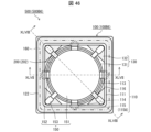
- FIG. 11 is a plan view showing an example of a battery module according to a third embodiment with a lid removed. 50 is a cross-sectional view taken along line L in FIG. 49 .
- FIG. 11 is a cross-sectional view of a battery module according to embodiment 3 having a metal frame.
- the top electrode of the electrochemical element is electrically connected to the lid member by an elastic member between the lid member and the second electrode, resulting in electrical conduction to the outside at the lid member.
- the lid side of the battery package and the first surface side of the insulating substrate may be referred to as the upper side
- the insulating substrate side of the battery package and the second surface side of the insulating substrate may be referred to as the lower side
- the top-bottom direction may also be referred to as the height direction (thickness direction). This distinction between top and bottom is for convenience, and does not limit the top and bottom when the battery module, etc. is actually used.
- Battery modules 500A, 500A1 to 500A9 described in embodiment 1 are an example of a battery module 500 according to the present disclosure.
- battery packages 100A, 100A1 to 100A9 described in embodiment 1 are an example of a battery package 100 according to the present disclosure.
- FIG. 1 is a perspective view showing the appearance of an example of a battery module 500A according to embodiment 1.
- FIG. 2 is an exploded perspective view of the battery module of FIG. 1.
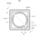
- FIG. 3 is a plan view showing an example of the battery module of FIG. 1 with the lid removed.
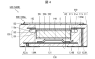
- FIG. 4 is a cross-sectional view taken along line IV in FIG. 3.
- FIG. 5 is a bottom view showing an example of the battery module of FIG. 1.
- each plan view, and bottom view, some of the first electrodes, etc. are shaded in a dot pattern to make them easier to distinguish from others.
- the battery module 500A includes a battery package 100A and one or more batteries 200 housed in the recess 113 of the battery package 100A.
- the battery package 100A may include an insulating substrate 110, a conductive elastic member 140, a conductive member 150, and a lid 160.
- the insulating substrate 110 has a first surface 111, a second surface 112 located on the opposite side to the first surface 111, and a recess 113 that opens into the first surface 111.
- one battery 200 is housed in the recess 113.
- the insulating substrate 110 may be made of an insulating inorganic material.
- the insulating inorganic material include ceramics such as aluminum oxide sintered body (alumina ceramics), aluminum nitride sintered body, mullite sintered body, or glass ceramic sintered body.
- the insulating substrate 110 may be made of a plurality of laminated insulating layers or a single insulating layer.
- the insulating layer is made of an insulating material such as aluminum oxide sintered body, glass ceramic sintered body, mullite sintered body, or aluminum nitride sintered body.
- the insulating substrate 110 is produced as follows. That is, first, a ceramic green sheet that will become the insulating layer is produced. A raw material powder such as aluminum oxide and silicon oxide is formed into a sheet shape together with an appropriate organic binder and organic solvent to produce a plurality of rectangular ceramic green sheets. Next, these ceramic green sheets are stacked to produce a laminate. The recess 113 and the second recess 114 are formed by providing through holes in the ceramic green sheets using a mold or the like. The laminate is then fired at a temperature of 1300 to 1600°C to produce the insulating substrate 110.
- the dimensions of the insulating substrate 110 are, for example, a rectangular side length of 1 mm to 20 mm, and a thickness of the insulating substrate 110 of 0.5 mm to 5 mm.
- the dimensions of the recess 113 of the insulating substrate 110 can be set according to the size of the battery 200.
- the size of the recess 113 in a plan view is slightly larger than the size of the battery 200 in a plan view.
- the inner wall surface of the recess 113 may be parallel to the thickness direction of the insulating substrate 110.
- the depth of the recess 113 is greater than the height of the battery 200 housed in the recess 113, the compressed elastic member 140, and the conductive member 150 overlapping each other.
- the shape of the recess 113 in a plan view is not limited to a circular shape, and can be changed depending on the shape of the battery 200.
- the insulating substrate 110 has a second recess 114 that opens into the inner wall surface of the recess 113.
- the insulating substrate 110 may have two second recesses 114.
- the two second recesses 114 may be opposed to each other with the recess 113 in between.
- the number of second recesses 114 is not limited to two, and multiple second recesses 114 may be formed along the inner circumference of the recess 113.
- the second recess 114 may be a single recess formed over the entire inner circumference of the recess 113.
- the second recess 114 may be a groove formed over the inner circumference of the recess 113.
- the insulating substrate 110 also includes a fixing portion 115.
- the fixing portion 115 is a component that restricts the conductive member 150 from moving in a direction away from the bottom surface of the recess 113.
- the battery 200 housed in the recess 113 is sandwiched between the elastic member 140 and the conductive member 150.
- the battery 200 is pressed against the conductive member 150 by the elastic member 140, and the conductive member 150 is restricted in movement by the fixing portion 115.
- the battery 200 is fixed in a state where it is pressed against the conductive member 150.
- the elastic member 140 can absorb manufacturing errors such as variations in the height of the battery 200 and the depth of the recess 113, as well as expansion and contraction of the battery 200.
- the elastic member 140 can absorb impacts when assembling the battery module 500 (500A).
- the insulating substrate 110 has, for example, an engaging portion 115A as the fixing portion 115.
- the engaging portion 115A is a portion of the insulating substrate 110 that is located above the second recess 114.
- the engaging portion 115A has an engaging surface 115a that faces the second surface 112.
- the engaging surface 115a can also be said to be the upper surface (ceiling) of the second recess 114.
- the engaging portion 115A may be a protruding portion that protrudes from the inner wall surface of the recess 113 toward the center of the recess 113.
- the height from the bottom surface of the recess 113 to the locking surface 115a is smaller than the height of the battery 200 housed in the recess 113, the elastic member 140 in an uncompressed state, and the conductive member 150, and is equal to the height of the battery 200, the elastic member 140 in a compressed state, and the conductive member 150, which are stacked together.
- the insulating substrate 110 has two locking portions 115A as shown in Figures 3 to 5.
- the two locking portions 115A face each other, sandwiching the recess 113.
- the two locking portions 115A are located at opposing corners of the insulating substrate 110.
- the position of the conductive member 150 can be stabilized.
- an area for providing the locking portions 115A can be easily secured, and the battery module 500A can be made smaller.
- the battery package 100A includes a wiring conductor 130 on the surface and inside of the insulating substrate 110.
- the wiring conductor 130 includes a first electrode 131, a second electrode 132, a first connection wiring 133A, a second connection wiring 133B, a first external electrode 134A, and a second external electrode 134B.
- the first electrode 131 is located on the bottom surface of the recess 113 and is electrically connected to the first external electrode 134A by the first connection wiring 133A.
- the first electrode 131 may cover the entire bottom surface of the recess 113.
- the first electrode 131 may also extend from the bottom surface of the recess 113 to the inside of the insulating substrate 110 as shown in FIG. 4.
- the first connection wiring 133A is located in a thick part of the insulating substrate 110, so that it is superior in terms of strength.
- the first electrode 131 may be contained within the bottom surface of the recess 113 in a planar view.
- the first electrode 131 may not extend to the inside of the insulating substrate 110, and the first connection wiring 133A may penetrate from the bottom surface of the recess 113 to the second surface 112 and connect to the first external electrode 134A.
- the path from the battery 200 to the first external electrode 134A is shorter and has lower resistance, improving the efficiency of extracting power from the battery 200 housed in the recess 113.
- the second electrode 132 is located on the insulating substrate 110 and is electrically connected to the second external electrode 134B by the second connection wiring 133B.
- the second electrode 132 may be located on at least one of the engagement surfaces 115a of the insulating substrate 110.
- the second electrode 132 may extend from the engagement surface 115a to the inside of the insulating substrate 110.
- the second electrode 132 may cover the entire surface of the engagement surface 115a.
- the second electrode 132 is located on each of the engagement surfaces 115a of the two engagement portions 115A in the insulating substrate 110.
- the first external electrode 134A and the second external electrode 134B are each located on the second surface 112 of the insulating substrate 110.
- the first external electrode 134A and the second external electrode 134B may extend from the second surface 112 of the insulating substrate 110 to the side surface (including the corner between the side surfaces).
- the battery package 100A in other words, the battery module 500A, can be surface mounted on a mounting substrate.
- the elastic member 140 may be any elastic and conductive member, and may be, for example, a leaf spring or a disc spring that is positioned so as to be convex in a direction away from the bottom surface of the recess 113, as shown in Figures 2 and 4.
- the elastic member 140 is positioned on the first electrode 131, and when one or more batteries 200 are housed in the recess 113, it is positioned between the first electrode 131 and the bottom electrode 201 of the battery 200.
- the first electrode 131 and the bottom electrode 201 of the battery 200 housed in the recess 113 are electrically connected via the elastic member 140.
- the elastic member 140 biases the battery 200 in a direction away from the bottom surface of the recess 113.
- the conductive member 150 is a member for electrically connecting the upper electrode 202 of the battery 200 and the second electrode 132.
- the conductive member 150 may be formed, for example, from a metal plate.
- the conductive member 150 abuts against the upper electrode 202 of the battery 200 housed in the recess 113.
- the conductive member 150 abuts against the upper electrode 202 of the battery 200 that is furthest from the bottom surface of the recess 113.
- the material of the conductive member 150 may be a metal. By using a metal, a conductive member 150 with excellent conductivity and durability can be realized.
- the conductive member 150A includes a main body portion 151 that contacts the upper electrode 202 of the battery 200, and a fixed portion 152 that is fixed to the corresponding locking portion 115A.
- the main body portion 151 may have a shape that overlaps with the battery 200 or is slightly smaller than the battery 200 when the battery module 500A is viewed from above.
- the main body portion 151 contacts the upper electrode 202 of the battery 200 that is furthest from the bottom surface of the recess 113.
- the fixed portion 152 is a portion that extends radially outward from the main body portion 151 in a plan view.
- the fixed portion 152 may extend in a straight line from the main body portion 151 in a cross-sectional view. Alternatively, the fixed portion 152 may have a curved or bent portion. In either case, the elastic force of the fixed portion 152 can be set according to the width, thickness, and shape of the fixed portion 152, and the force with which the fixed portion 152 is pressed against the second electrode 132 can be adjusted. Also, the force with which the main body portion 151 is pressed against the upper electrode 202 of the battery 200 can be adjusted. As a result, the reliability of the electrical connection between the second electrode 132 and the conductive member 150, and between the battery 200 and the conductive member can be improved.
- the height LM of the elastic member 140 in the compressed state can be set according to the depth of the recess 113, the thickness of the locking portion 115A, the thickness of the conductive member 150, the dimensions (thickness) of the battery, etc.
- the fixed portion 152 becomes more likely to be locked to the locking portion 115A.
- the height LM of the elastic member 140 in the compressed state is the distance between the bottom surface of the battery 200 and the bottom surface of the peripheral portion of the elastic member 140 (the portion abutting the recess 113).
- the deformation amount of the elastic member 140 is the difference between the height in the uncompressed state and the height in the compressed state.
- the conductive member 150 is pressed against the engaging surface 115a by one or more batteries 200 biased by the elastic member 140, and the upper surface of the conductive member 150 abuts against the engaging surface 115a of the second electrode 132, electrically connecting the second electrode 132 to the upper surface of the conductive member 150.
- the lower surface of the conductive member 150 abuts against the upper electrode 202 of the battery 200, so that the conductive member 150 and the battery 200 are electrically connected. This electrically connects the upper electrode of the battery 200 to the second electrode 132.
- the conductive member 150 and the upper electrode 202 may be joined by, for example, a conductive bonding material.
- the conductive member 150 may be integrated with the exterior of the battery 200. When two or more batteries are housed in the recess 113, the conductive member 150 may be fixed to the upper electrode 202 of the battery 200 that is furthest from the bottom surface of the recess 113.
- the lid 160 may close the opening of the recess 113.
- the lid 160 is electrically insulated from the first electrode 131 and the second electrode 132.
- the lid 160 is made of metal.
- the frame-shaped metal film 122 may be positioned on the first surface 111, and the lid 160 may be joined onto the frame-shaped metal film 122.
- the frame-shaped metal film 122 may be formed on the first surface 111 by metallization.
- a nickel film may be formed by plating on the surfaces of the frame-shaped metal film 122 and the lid 160 to improve the joining property with the brazing material.
- the metal lid 160 it is preferable to use a material that has a small thermal expansion difference with ceramics, and for example, an iron-nickel (Fe-Ni) alloy or an iron-nickel-cobalt (Fe-Ni-Co) alloy may be used.
- an iron-nickel (Fe-Ni) alloy or an iron-nickel-cobalt (Fe-Ni-Co) alloy may be used.
- the opening of the recess 113 is closed with the lid 160, so that the space S surrounded by the lid 160 and the insulating substrate 110 is hermetically sealed or vacuum sealed.
- the lid 160 and the frame-shaped metal film 122 may be joined using a joining material such as a brazing material. In this case, the entire surface is heated by reflow heating.
- direct seam welding, laser welding, or electron beam welding may be used to join the lid 160 and the frame-shaped metal film 122. These welding methods are joining by localized heating of the joint, so that hermetically sealing or vacuum sealing can be achieved at a lower temperature than when brazing is used, which is joining by overall heating (reflow heating). Sealing at a low temperature reduces the thermal impact on the battery 200, and a low dew point airtight environment or low dew point vacuum environment can be achieved.
- the ratio of the gap volume to the volume of the space S may be set to, for example, 5% to 30%.
- the gap amount between the lid body 160 and the conductive member 150 may be set to, for example, 0.1 mm to 0.8 mm. These may be set for the battery module 500A in an initial state in which the battery 200 is not expanded and no external force is applied to the lid body 160.
- the space S may be sealed in an atmosphere such as a nitrogen atmosphere, an argon gas atmosphere, or a vacuum, with a dew point of, for example, -20 degrees or less.
- an atmosphere such as a nitrogen atmosphere, an argon gas atmosphere, or a vacuum, with a dew point of, for example, -20 degrees or less.
- Battery 200 may be a coin battery in which battery materials such as an electrolyte material, a positive electrode, a negative electrode, and a separator are placed in a metal container and sealed. Coin batteries are sometimes called button batteries. Battery 200 may be a primary battery or a secondary battery. Battery 200 also includes not only chemical batteries, but also power supply elements such as electric double layer capacitors and electric double layer capacitors.
- the battery 200 has electrodes (upper electrode 202, lower electrode 201) on the upper and lower surfaces.
- the upper electrode 202 of the battery 200 is a positive electrode or a negative electrode.
- the battery 200 is surface-mounted on a mounting substrate.
- the internal configuration and materials of the battery 200 are not particularly limited as long as the battery 200 has electrodes on the upper and lower surfaces.
- the battery 200 may be an all-solid-state battery having a structure in which a solid electrolyte is sandwiched between a positive electrode and a negative electrode.
- the battery 200 may have a current collector on the outside of the positive electrode and the negative electrode.
- the battery 200 may be round or cylindrical, square or prismatic, or another shape.
- the battery 200 is a coin battery that cannot be surface-mounted on a mounting board by itself, it can be surface-mounted on a mounting board by using the battery package 100A.
- the battery material of the battery 200 is a sulfide-based battery material, by using an already sealed coin battery, it can be easily sealed and made into a surface-mount type even if the working environment is not a special dry atmosphere.
- it can be surface-mounted on a mounting board even if the working environment is not a special dry atmosphere, which increases the productivity of the circuit board device.
- the battery package 100A allows the coin battery to be hermetically sealed at a higher level than a typical coin battery.
- the positive and negative electrodes are sealed with a resin material such as a gasket, so there is a concern that moisture may infiltrate from the outside over time, causing deterioration of the battery material.
- the hermetic sealing provided by the battery package 100A of the present disclosure can block the intrusion of moisture from the outside into the coin battery. Blocking moisture improves the life of the coin battery.
- sulfide-based batteries there is a concern that moisture infiltrating from the external environment may cause hydrogen sulfide and other substances to be generated. Blocking moisture can reduce the generation of hydrogen sulfide and other substances.
- the battery material is doubly sealed by the metal container and the battery package 100A, so leakage of sulfide material from the battery package 100A can be significantly reduced.
- the elastic member 140 is positioned between the battery 200 and the first electrode 131, so the elastic member 140 is not electrically connected to the lid body 160 or the like and is not electrically connected to the outside of the battery package 100A. This prevents discharge to the outside from members other than the external electrodes, such as the lid body 160, so power can be efficiently extracted from the battery 200 via the first external electrode 134A and the second external electrode 134B.
- the battery package 100A is provided with a conductive member 150 and an elastic member 140 that are fixed to the fixing portion, so that the battery can be fixed without using conductive resin. This makes it possible to realize a battery module with high long-term reliability. Furthermore, by providing the elastic member 140, it is possible to absorb variations in the height of the battery or the depth of the recess in the battery package.
- FIG. 6 is a bottom view of a battery package 100A1 in which a seal pattern is formed on the second surface of the insulating substrate.
- the second surface 112 of the insulating substrate 110 may have a seal pattern 136 surrounding the first external electrode 134A and the second external electrode 134B.
- the seal pattern 136 is made of a conductive material such as a solderable metal.
- the seal pattern 136 may surround each of the first external electrode 134A and the second external electrode 134B.
- the first external electrode 134A and the second external electrode 134B located inside the seal pattern 136 can be sealed.
- the battery package 100A1 or the battery module 500A1 can be mounted on the substrate so that neither the first external electrode 134A nor the second external electrode 134B of the battery package 100A1 is exposed to the external environment. Therefore, even if water penetrates the mounting substrate, no electrical short circuit occurs between the first external electrode 134A and the second external electrode 134B, and no leakage current occurs from the battery module 500A1.
- sealing by solder joining can be performed simultaneously with joining the first external electrode 134A and the second external electrode 134B to the electrodes of the mounting substrate with solder.
- the periphery of the battery module 500A can be sealed with a sealing material such as a resin material.
- the battery package 100A or the battery module 500A can be mounted on the substrate so that neither the first external electrode 134A nor the second external electrode 134B of the battery package 100A is exposed to the external environment.
- the elastic member 140 is not limited to the example shown in FIG. 4, and may be, for example, a leaf spring of another shape, a coil spring formed from a metal wire, conductive rubber, or conductive sponge.
- the elastic member 140 may be a leaf spring 140A that is convex in a direction approaching the bottom surface of the recess 113 as shown in FIG. 7.
- the leaf spring may be dish-shaped or hat-shaped, and may have a through hole or slit.
- the leaf spring may be a plurality of leaf springs in which a hat-shaped spring is divided.
- the elastic member 140 may be configured to include at least one cantilever spring 140B as shown in FIG. 8, or may be configured to include a plurality of cantilever springs as shown in FIG. 24. When a cantilever spring 140B is used, multiple cantilever springs may be evenly arranged.
- the elastic member 140 may be a coil spring 140C as shown in FIG. 9.
- the elastic member 140 may be a leaf spring or a disc spring positioned so as to be convex from the lower electrode 201 of the battery 200 toward the bottom surface of the recess 113. Furthermore, the elastic member 140 may be fixed to the lower electrode 201 of the battery 200 and integrated with the exterior of the battery 200. When two or more batteries are housed in the recess 113, the elastic member 140 may be fixed to the lower electrode 201 of the battery 200 closest to the bottom surface of the recess 113.
- the elastic member 140 may be a conductive rubber or a conductive sponge.
- GMS graphene meso sponge
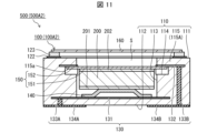
- FIG. 11 is a cross-sectional view of a battery module 500A2 including a battery package 100A2 having a metal frame.
- the battery package 100A2 may have a metal frame 123 located above the first surface 111.
- the metal frame 123 may be joined to the frame-shaped metal film 122 by brazing material, and the lid 160 may be joined to the metal frame 123.
- the metal frame 123 and the lid 160 may be joined by, for example, seam welding, direct seam welding, laser welding, or electron beam welding.
- seam welding is resistance welding via the metal frame 123, and is advantageous in terms of localized heating of the joint.
- a current is applied to the lid 160 during seam welding, the lid 160 is not electrically connected to the battery 200, so the battery 200 is not damaged by the current during seam welding.
- the conductive member 150 is located between the lid 160 and the battery 200, the impact of radiant heat from the lid 160 generated during welding on the battery 200 is also reduced.
- a nickel film may be formed on the surface of the metal frame 123 by plating to improve bonding with brazing material.
- the metal frame 123 should be made of a material that has a small thermal expansion difference with ceramics, such as an iron-nickel (Fe-Ni) alloy or an iron-nickel-cobalt (Fe-Ni-Co) alloy.
- FIG. 12 and 13 are plan views of a battery package 100A3 and a battery package 100A4, respectively, having locking parts in a different form from the battery package 100A shown in Figs. 1 to 5. They are plan views showing another state of the locking parts provided on the insulating substrate.
- Fig. 14 is a cross-sectional view taken along line XIV in Fig. 13.
- the direction of the line connecting the two opposing locking portions 115A may be in any direction.
- the locking portion 115A may be located on a side of the insulating substrate 110 instead of a corner.
- the second recess 114 may open to the first surface 111 as if a notch had been made from the recess 113.
- the end of the upper surface of the second recess 114 is located outside the end of the lower surface in a plan view.
- the inner surface of the locking portion 115A is located outside the inner wall surface of the recess 113. The opening of the second recess 114 guides the insertion of the fixed portion 152 into the second recess 114, facilitating engagement between the fixed portion 152 and the locking portion 115A.
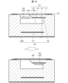
- FIG. 15 is a cross-sectional view showing how to assemble the battery module 500A shown in Fig. 1, which has an inclined surface at the locking portion 115A.
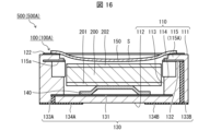
- Fig. 16 is a cross-sectional view showing how to assemble the battery module 500A shown in Fig. 1, which has a stepped surface at the locking portion 115A.
- the conductive member 150 is inserted into the recess 113 by being pushed into the recess 113 so as to be deformed convexly downward.
- the upper surface of the locking portion 115A may be a stepped surface or an inclined surface approaching the center of the recess 113.
- the protrusion amount of the locking portion 115A may gradually increase from the first surface 111 side toward the second surface 112 side.
- the inclination angle of the inclined surface approximating this stepped surface or the inclination angle of this inclined surface may be in the range of 1 degree to 45 degrees with respect to the thickness direction of the insulating substrate 110.
- the number of steps of the stepped surface may be one step or two or more steps. Even if there is a dimensional error in the insulating substrate 110 or the conductive member 150, or both, the stepped shape or inclined surface allows the fixed portion 152 of the conductive member 150 to be smoothly inserted into the second recess 114.
- the conductive member 150 may have a material or a shape that is easily deformed downwardly convex, or both. This makes it easy to insert the conductive member 150 into the recess 113.
- the conductive member 150 may also have a material or a shape that is difficult to deform upwardly convex, or both. This makes it difficult for the fixed portion 152 of the conductive member 150 to come out of engagement with the locking portion 115A.
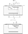
- FIG. 17 is a plan view showing how the battery module 500A5 is assembled.
- the insulating substrate 110 of the battery module 500A5 opens to the first surface 111 and the recess 113 on the side of the locking portion 115A.
- the second recess 114 of the battery module 500A5 opens to the first surface 111 on the side of the locking portion 115A.
- FIG. 18 is a cross-sectional view taken along lines XVIII-A and XVIII-B in FIG. 17.
- FIG. 19 is a cross-sectional view showing another example of engagement between the fixed portion and the locking portion.
- FIG. 20 is a cross-sectional view taken along lines XX-A and XX-B in FIG. 17.
- the second recess 114 of the battery package 100A5 may open into the recess 113 below the locking portion 115A, and may open into the first surface 111 and the recess 113 on the side of the locking portion 115A. This configuration guides the insertion of the fixed portion 152 into the second recess 114 and below the locking portion 115A, and makes it easier to fix the conductive member 150.
- the fixed part 152 and the main body part 151 are inserted into the second recess 114 and the recess 113, respectively, through the opening in the first surface 111.
- the conductive member 150 is rotated to move the fixed part 152 below the locking part 115A.
- the upper surface of the main body part 151 may have irregularities or protrusions.
- the corner of the fixed part 152 on the front side in the rotational direction may be chamfered so that the fixed part 152 can easily move downward of the locking part 115A.
- the corner of the locking part 115A on the side that meets the fixed part 152 may be chamfered so that the fixed part 152 can easily move downward of the locking part 115A.
- the entire part or the tip of the fixed part 152 may be angled with the main body part 151 so that the front side in the rotational direction is lower so that the fixed part 152 can easily move downward of the locking part 115A.
- the configuration in which the fixed part 152 is angled with the main body part 151 can further reduce the possibility that the fixed part 152, which has once entered below the locking part 115A due to rotation, will move back.
- the surface of the fixed portion 152 that comes into contact with the insulating substrate 110 may be rough so that the conductive member 150 is less likely to rotate in reverse due to vibration of the battery package 100 (100A).
- Fig. 21 is a partially enlarged cross-sectional view of a battery module 500A using a battery 200X, which is a thin-film all-solid-state battery, as the battery.
- Fig. 22 is a partially enlarged cross-sectional view of a battery module 500A using a plurality of thin-film all-solid-state batteries 200X as the battery.
- the battery module 500A may include a battery 200X that is a thin-film type all-solid-state battery.
- the battery 200X has a configuration in which an anode layer 220, an electrolyte layer 230, and a cathode layer 240 are laminated on a metal plate 210, and the metal plate 210 functions as a current collector.
- the metal plate 210 is, for example, a plate of copper, aluminum, stainless steel, or the like, and the thickness of the metal plate 210 is, for example, 0.1 mm to 0.5 mm.
- the anode layer 220, the electrolyte layer 230, and the cathode layer 240 are formed, for example, by a deposition method or a sputtering method.
- the battery 200X may include a resin cover 250 that covers the end face of the anode layer 220, the end face of the electrolyte layer 230, and the end face of the cathode layer 240, and the resin cover 250 is made of insulating resin.
- the battery module 500A may include an all-solid-state battery that is not a thin-film type.
- the metal plate 210 corresponds to the bottom electrode 201
- the positive electrode layer 240 corresponds to the top electrode 202.
- the negative electrode layer 220, electrolyte layer 230, and positive electrode layer 240 are stacked in this order from the bottom metal plate 210, but the negative electrode layer 220 and the positive electrode layer 240 may be stacked in reverse. In this case, the negative electrode layer 220 corresponds to the top electrode 202.
- the position of the end face of the anode layer 220, the position of the end face of the electrolyte layer 230, and the position of the end face of the cathode layer 240 may be offset.
- the anode layer 220, the electrolyte layer 230, and the cathode layer 240 may be stacked in the order of smaller or larger.
- the electrolyte layer 230 may be made larger than the cathode layer 240 and the anode layer 220. In this case, the possibility of a short circuit between the cathode layer 240 and the anode layer 220 in the lateral direction can be reduced.
- the battery module 500A may include a plurality of batteries 200X.
- the plurality of batteries 200X may be stacked vertically in series in the recess 113 of the battery package 100.
- a conductive adhesive may be interposed between the plurality of batteries 200X.
- the end of the electrolyte layer 230 may cover the end of the negative electrode layer 220.
- the plurality of batteries 200X are efficiently manufactured by forming a thin-film battery on a large metal plate and cutting it into individual pieces of a predetermined size.
- the plurality of batteries 200X may be connected by contact without an adhesive. The contact resistance between the plurality of batteries 200X can be reduced by sandwiching the plurality of batteries 200X between the elastic member 140 and the conductive member 150 and pressing them.
- thin-film all-solid-state batteries have high energy density, high safety, and excellent recycle life.
- mass production of the battery 200X becomes possible, improving the productivity of the battery module 500A.
- the battery 200X is cut out to a size that matches the recess 113 of the insulating substrate 110 by dicing or the like, and is placed in the recess 113 of the insulating substrate 110. This improves the productivity of the battery module 500A.
- the adhesion between the metal plate 210 and the negative electrode layer 220, the adhesion between the negative electrode layer 220 and the electrolyte layer 230, and the adhesion between the positive electrode layer 240 and the electrolyte layer 230 are increased. This increases the efficiency of extracting power from the battery 200X.
- the fixing portion 115 is a locking metal fitting or a fixing metal film that is fixed or joined to the insulating substrate 110.
- Figure 23 is a plan view of battery module 500A6 with the lid removed.
- Figure 24 is a cross-sectional view taken along line XXIV in Figure 23.
- Figure 25 is a plan view of battery module 500A7 with the lid removed.
- Figure 26 is a cross-sectional view of battery module 500A8.
- the insulating substrate 110 may include, as the fixing portion 115, a locking metal fitting 115B fixed or joined to the insulating substrate 110.
- the insulating substrate 110 including the locking metal fitting 115B is easy to manufacture.
- the strength of the insulating substrate 110 can be improved, and the strength of the fixing portion 115 can be improved.
- the insulating substrate 110 may include a notch 116 (see FIG. 24) that opens to the first surface 110 and the recess 113 so that the locking metal fitting 115B and the conductive member 150 are unlikely to come into contact with the lid body 160, and the locking metal fitting 115B may be joined to the bottom surface of the notch 116.
- the depth of the notch 116 may be greater than the height of the locking metal fitting 115B so that the locking metal fitting 115B and the conductive member 150 are unlikely to come into contact with the lid body 160. If the depth of the notch 116 is equal to or smaller than the height of the locking metal fittings 115B, a metal frame 123 or an insulating frame made of a ceramic material, or both, may be located between the insulating substrate 110 and the lid 160. In FIG. 23, the bottom surface of the notch 116 may be regarded as the first surface 110, and the part of the insulating substrate 110 rising outside the notch 116 may be regarded as the insulating frame. That is, the insulating substrate 110 may have the locking metal fittings 115B on the first surface 110 and the insulating frame on the outside of that.
- the locking metal fitting 115B may be fixed to the insulating substrate 110 with the conductive member 150 pressed against the battery 200.
- the locking metal fitting 115B may be joined to the fixing metal film 115C on the insulating substrate 110.
- the fixing metal film 115C may also serve as the second electrode 132 (see FIG. 26).
- the locking fitting 115B may open to the recess 113 and to the side.
- the fixed portion 152 is inserted into the locking fitting 115B through the side opening of the locking fitting 115B.
- the insulating substrate 110 may include, for example, a fixing metal film 115C as the fixing portion 115.
- the fixed portion 152 may be joined to the fixing metal film 115C by brazing, soldering, or metal welding using laser irradiation.
- the insulating substrate 110 including the fixing metal film 115C is easy to manufacture.
- the strength of the insulating substrate 110 can be improved, and the strength of the fixing portion 115 can be improved.
- the fixing metal film 115C may also serve as the second electrode 132.
- the fixing metal film 115C may be located on the bottom surface of the cutout 116 so that the conductive member 150 is unlikely to come into contact with the lid 160.
- a frame may be located between the insulating substrate 110 and the lid 160 so that the conductive member 150 is unlikely to come into contact with the lid 160.
- FIG. 27 is a cross-sectional view of the battery module 500A9 in which the conductive member is reversible.
- the conductive member 150 may be a reversible leaf spring having a convex portion in the center that presses the battery 200 from above by being inverted upside down.
- the upper view of FIG. 27 is a cross-sectional view showing the state of the conductive member 150 before being inverted, and the lower view of FIG. 27 is a cross-sectional view showing the state of the conductive member 150 after being inverted.
- the conductive member 150 may be inserted into the second recess 114 and the recess 113 in an upwardly convex shape.
- the conductive member 150 may be in an upwardly convex shape before the fixed portion 152 is inserted into the second recess 114.
- the conductive member 150 may be inverted to a downwardly convex shape during or after insertion.
- the battery is pressed downward by the main body portion 151 of the conductive member 150 in a downwardly convex shape, and the elastic member 140 is compressed.
- the compressed elastic member 140 presses the battery 200 against the conductive member 150, and the conductive member 150 is restricted in movement by the fixing portion 115, thereby fixing the battery 200.
- the battery package 100A9 can accommodate batteries 200 of various thicknesses and various numbers.
- the conductive member 150 In the configuration for rotating the conductive member 150 described above with reference to Figures 17 to 20, while the conductive member 150 is rotating, the conductive member 150 has an upwardly convex shape, so that the fixed portion 152 does not come into contact with the locking surface 115a, and the conductive member 150 can rotate easily. After the conductive member 150 is positioned below the locking portion 115A, the conductive member 150 is inverted to become downwardly convex, so that the fixed portion 152 can come into contact with the locking surface 115a. This contact electrically connects the fixed portion 152 to the second electrode 132.
- Battery modules 500B, 500B2 to 500B6 described in embodiment 2 are examples of battery modules 500 according to the present disclosure.
- Battery packages 100B, 100B2 to 100B6 described in embodiment 2 are examples of battery packages 100 according to the present disclosure.
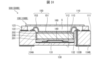
- FIG. 28 is a plan view showing the battery module 500B with the lid removed.
- FIG. 29 is a cross-sectional view taken along line XXIX in FIG. 28.
- FIG. 30 is a cross-sectional view taken along line XXX in FIG. 28.
- the conductive member 150 includes a main body portion 151, a connection portion 153, and a fixed portion 152.
- the main body portion 151 is a portion that abuts against the upper electrode 202 of the battery 200.
- the connection portion 153 is a portion that is electrically connected to the corresponding second electrode 132.
- the fixed portion 152 is a portion that is fixed to the corresponding fixing portion 115. When the fixing portion 115 is the locking portion 115A, the fixed portion 152 is a portion that is locked to the locking portion 115A.
- the conductive member 150 may have only one connection portion 153, or two or more. Two or more connection portions 153 can improve the reliability of the electrical connection between the second electrode 132 and the conductive member 150.
- the conductive member 150 may have two or more fixed portions 152. The center of the force pressing against the battery 200 may be located on a line segment or within a polygon connecting the two or more fixed portions 152. The two fixed portions 152 may be located at diagonal corners of the insulating substrate 110.
- the connecting portion 153 and the fixed portion 152 each extend radially outward from the main body portion 151 in a plan view.
- the elastic force of the connecting portion 153 can be set according to the width, thickness, and shape of the connecting portion 153, and the force with which the connecting portion 153 is pressed against the second electrode 132 can be adjusted.
- the elastic force of the fixed portion 152 can be set according to the width, thickness, and shape of the fixed portion 152, and the force with which the main body portion 151 is pressed against the upper electrode 202 of the battery 200 can be adjusted. As a result, the reliability of the electrical connection between the second electrode 132 and the conductive member 150, and between the battery 200 and the conductive member can be improved.
- the extension direction of the connection portion 153 may be different from the extension direction of any of the fixed portions 152 in a plan view.
- the extension direction of the connection portion 153 forms an angle with the extension direction of the nearest fixed portion 152 in a plan view. "Forming an angle” means that the angle between the two directions is greater than 0 degrees. Since the connection portion 153 and the fixed portion 152 are located in different directions with respect to the center of the recess 113 in a plan view, the second electrode 132 is disposed in a different direction from the locking portion 115A.
- the fixing portion 115 and the second electrode can be disposed in positions where they do not overlap in a plan view.
- the two fixing parts 115 and the two second electrodes 132 can be disposed at the four corners of the insulating substrate 110 in a plan view.
- the intersection angle is approximately 90°. This allows the battery package 100B to be made smaller.
- the insulating substrate 110 has a notch 116 that opens to the first surface 111 and the recess 113, and the second electrode 132 may be located on the bottom surface of the notch 116.
- the battery package 100 may have a plurality of second electrodes 132 and a plurality of locking portions 115A.
- the two second electrodes 132 may be located at positions facing each other across the recess 113
- the two locking portions 115A may be located at positions facing each other across the recess 113.
- the line connecting the two second electrodes 132 and the line connecting the two locking portions 115A may form an angle.
- the elastic member 140 rotates and twists around the line connecting the opposing locking portions 115A as a central axis, at least one of the two connection portions 153 will abut against the second electrode 132.
- the three or more locking portions 115A may be positioned in line symmetry or rotational symmetry to surround the recess 113.
- connection portion 153 and the fixed portion 152 may each extend in a straight line from the main body portion 151, or may have a curved or bent portion between the connection portion with the main body portion 151 and the end.
- connection portion 153 has a U-shaped curved portion that is convex upward (toward the lid body 160) and a flat portion that abuts against the second electrode 132.
- connection portion 153 of the conductive member 150 has a different shape.
- the connection portion 153 has a convex portion that protrudes toward the lid body 160 and a flat portion that abuts against the second electrode 132.
- connection portion 153 has a convex portion that protrudes toward the lid 160, a flat portion that abuts the second electrode 132, and an end that is curved (rounded) upward.
- connection portion 153 has a convex portion that protrudes toward the lid 160, and an end that is curved downward. Because the end is curved, the conductive member 150 can be smoothly inserted into the recess 113 even if the connection portion 153 contacts the insulating substrate 110.
- connection portion 153 by having the connection portion 153 have a curved or bent portion, it is easy to adjust the elastic force according to the width and shape of the connection portion 153. In addition, depending on the shape of the curved or bent portion, it is easy to adjust the force with which the connection portion 153 abuts against the second electrode 132. In addition, by having the connection portion 153 have a curved or bent portion, it can have elasticity in a direction transverse to the main body portion 151, i.e., in the radial direction. Furthermore, the connection portion 153 may have elasticity in the thickness direction of the main body portion 151. This elasticity can absorb dimensional errors in the thickness direction during manufacturing and impacts during assembly.
- connection portion 153 it is possible to accommodate changes in the thickness of the battery 200 relative to the thickness of the battery package 100, the depth of the recess 113, or the height from the bottom surface of the recess 113 to the engagement surface 115a.
- a conductive member 150 having a curved or bent portion one insulating substrate 110 and elastic member 140 can accommodate batteries of different thicknesses.
- the bending direction of the bent portion it is possible to change the range of thicknesses of the battery 200 that can be accommodated. For example, when the bent portion bends upward, it can accommodate thin batteries, and when it bends downward, it can accommodate thick batteries.
- the insulating substrate 110 may have a notch 116 that opens to the first surface 111 and the recess 113, and the second electrode 132 may be located on the bottom surface of the notch 116.
- the second electrode 132 may be located on the first surface 111. In either case, the second electrode 132 is exposed on the upward surface. Furthermore, the second electrode 132 abuts against the lower surface of the connection portion 153 of the conductive member 150 and is electrically connected.
- This configuration allows visual confirmation of the appearance of the second electrode 132 and the connection between the conductive member 150 and the second electrode 132. Furthermore, when the second electrode 132 is located on the first surface 111, the second electrode 132 and the frame-shaped metal film 122 can be formed in the same process. For example, the second electrode 132 and the frame-shaped metal film 122 can be formed in the same process by screen printing.
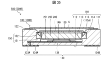
- Figures 34, 35, and 36 are cross-sectional views taken along the line XXVIII of the battery module 500B in Figure 28, showing an example in which the fixed portion 152 of the conductive member 150 has a different shape.
- the conductive member 150 has a bent portion that bends downward at the boundary between the main body portion 151 and the fixed portion 152 or at the fixed portion 152.
- the conductive member 150 may have a curved or bent portion in the fixed portion 152, and may have elasticity in a direction crossing the main body portion 151, i.e., in the radial direction.
- the fixed portion 152 deforms so as to shrink in the radial direction, making it easy to insert the conductive member 150 into the recess 113.
- the fixed portion 152 returns to its original shape so as to expand in the radial direction, and the fixed portion 152 is locked to the locking portion 115A.
- the conductive member 150 is less likely to shift in the radial direction.
- the upper surface of the locking portion 115A may be a stepped or inclined surface that approaches the center of the recess 113.
- the amount of protrusion of the locking portion 115A increases stepwise or gradually from the first surface 111 side toward the second surface 112 side.
- the inclination angle of the inclined surface approximating this stepped surface or the inclination angle of this inclined surface may be in the range of 1 degree to 45 degrees with respect to the thickness direction of the insulating substrate 110.
- Figure 37 is a plan view showing how to assemble the battery module 500B2.
- the insulating substrate 110 opens to the first surface 111 and the recess 113 on the side of the locking portion 115A.
- Figure 38 is a cross-sectional view taken along line XXXVIII in Figure 37.
- Figure 39 is a cross-sectional view taken along line XXXIX in Figure 37.
- the fixed part 152 and the main body part 151 are inserted into the second recess 114 and the recess 113, respectively, through the opening in the first surface 111. Thereafter, the fixed part 152 moves below the locking part 115A as the conductive member 150 rotates, and the fixed part 152 can be locked to the locking part 115A. As shown in Figure 38, the fixed part 152 may have a bent part that bends upward, and the tip of the fixed part 152 may be located above the main body part 151.
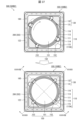
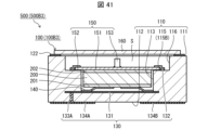
- Fig. 40 is a plan view of the battery module 500B3 with the lid removed.
- Fig. 41 is a cross-sectional view taken along line XLI in Fig. 40.
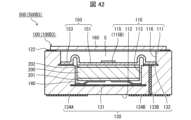
- Fig. 42 is a cross-sectional view taken along line XLII in Fig. 40.
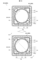
- Fig. 43 is a plan view of the battery module 500B4 with the lid removed.
- Fig. 44 is a cross-sectional view taken along line XLIV in Fig. 43.
- Fig. 45 is a cross-sectional view of the battery module 500B5.
- Fig. 46 is a plan view of the battery module 500B6 with the lid removed.
- Fig. 47 is a cross-sectional view taken along line XLVII in Fig. 46.
- Fig. 48 is a cross-sectional view taken along line XLVIII in Fig. 46.
- the insulating substrate 110 may include, as the fixing portion 115, for example, a locking fitting 115B that is fixed or joined to the insulating substrate 110.
- the locking fitting 115B may open to the recess 113 and to the side. By rotating the conductive member 150, the fixed portion 152 is inserted into the locking fitting 115B through the side opening of the locking fitting 115B.
- the insulating substrate 110 may include, for example, a fixing metal film 115C as the fixing portion 115.
- the fixed portion 152 may be joined to the fixing metal film 115C by brazing, soldering, or metal welding.
- the conductive member 150 may have four connection parts 153 and four fixed parts 152. However, the conductive member 150 may have three or five or more connection parts 153 and three or five or more fixed parts 152. The number of connection parts 153 and the number of fixed parts 152 of one conductive member 150 may be different.
- Battery modules 500C and 500C2 described in embodiment 3 are examples of the battery module 500 according to the present disclosure.
- battery packages 100C and 100C2 described in embodiment 3 are examples of the battery package 100 according to the present disclosure.
- Figure 49 is a plan view of battery module 500C with the lid removed.
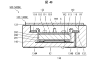
- Figure 50 is a cross-sectional view taken along line L in Figure 49.
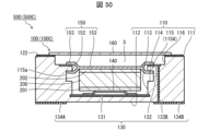
- Figure 51 is a cross-sectional view of battery module 500C2.
- Battery module 500C2 differs from battery module 500C in that it has a metal frame 123.
- the battery package 100C may have a connecting portion 153 that at least partially overlaps with the corresponding fixed portion 152 in a top perspective view.
- the locking portion 115A is sandwiched between the connecting portion 153 and the corresponding fixed portion 152. This configuration strengthens the fixation of the conductive member 150 to the insulating substrate 110. Since the connecting portion 153 and the fixed portion 152 are located in the same direction relative to the center of the recess 113 in a plan view, the second electrode 132 is located in the same direction as the locking portion 115A.
- the second electrode 132 is located at a corner of the insulating substrate 110, thereby making it possible to reduce the size of the battery package 100 (100C).
- the second electrode 132 can be positioned on the upper surface of the locking portion 115A. Therefore, the second electrode 132 can abut and electrically connect with the lower surface of the connection portion 153 of the conductive member 150. In addition, the appearance of the second electrode 132 and the connection between the conductive member 150 and the second electrode 132 can be visually confirmed.
- the fixed portion 152 is inserted into the second recess 114 by pushing the conductive member 150, as in the example shown in FIGS. 15 and 16.
- the fixed portion 152 may be configured to be inserted into the second recess 114 by rotating the conductive member 150, as in the example shown in FIGS. 17 and 18.
- the insulating substrate 110 may have a notch 116 that opens into the first surface 110 and the recess 113, and the second electrode 132 may be located on the bottom surface of the notch 116, so that the conductive member 150 is unlikely to come into contact with the lid 160.
- a metal frame 123 or an insulating frame, or both may be located between the insulating substrate 110 and the lid 160, so that the conductive member 150 is unlikely to come into contact with the lid 160.
- a first aspect of the present disclosure is a battery package comprising an insulating substrate having a first surface, a second surface opposite the first surface, and a recess opening onto the first surface, a first external electrode located on the second surface, a second external electrode located on the second surface, a first electrode located on a bottom surface of the recess and electrically connected to the first external electrode, a second electrode located on the insulating substrate and electrically connected to the second external electrode, a conductive elastic member located on the first electrode, and a conductive member abutting an upper electrode of a battery contained in the recess and electrically connecting the upper electrode and the second electrode, wherein the insulating substrate has a fixing portion that limits movement of the conductive member in a direction away from the bottom surface of the recess.
- Aspect 2 of the present disclosure is the battery package described in aspect 1 above, in which the second electrode is electrically connected to the upper surface of the conductive member.
- Aspect 3 of the present disclosure is a battery package according to aspect 1 or 2 above, in which the conductive member includes a main body portion that abuts against the upper electrode of the battery, a connection portion that extends outward from the main body portion in a plan view and is electrically connected to the second electrode, and a fixed portion that extends outward from the main body portion in a plan view and is fixed to the fixing portion.
- Aspect 4 of the present disclosure is the battery package described in aspect 3 above, in which the extension direction of the connection portion and the extension direction of the fixed portion form an angle.
- Aspect 5 of the present disclosure is a battery package as described in Aspects 3 or 4 above, in which the second electrode is electrically connected to the underside of the connection portion.
- Aspect 6 of the present disclosure is a battery package according to any one of aspects 1 to 5 above, having a plurality of the second electrodes and a plurality of the fixing portions.
- Aspect 7 of the present disclosure is a battery package according to aspect 6 above, in which the two second electrodes are positioned opposite each other across the recess, the two fixing parts are positioned opposite each other across the recess, and an angle is formed between a line connecting the two second electrodes and a line connecting the two fixing parts.
- Aspect 8 of the present disclosure is a battery package according to any one of aspects 1 to 7 above, in which the fixing portion is a locking portion having a locking surface that faces the second surface.
- Aspect 9 of the present disclosure is a battery package according to aspect 8 above, in which the upper surface of the locking portion is a stepped or inclined surface that approaches the center of the recess toward the bottom surface of the recess.
- Aspect 10 of the present disclosure is a battery package according to any one of aspects 3 to 5 above, or any one of aspects 6 to 9 above that cites aspect 3 above, in which the connection portion and the fixed portion overlap when viewed from above.
- Aspect 11 of the present disclosure is the battery package described in aspect 10 above, in which the second electrode is located on the upper surface of the fixing portion and is electrically connected to the lower surface of the connection portion.
- Aspect 12 of the present disclosure is a battery package according to aspect 8 or 9 above, or any one of aspects 9 to 11 above that cites aspect 8 above, in which the insulating substrate has a notch that opens into the recess below the engaging portion and opens into the first surface and the recess on the side of the engaging portion.
- Aspect 13 of the present disclosure is a battery package according to any one of aspects 3 to 5 above, or any one of aspects 6 to 12 above that cites aspect 3 above, in which the fixed portion and/or the connection portion have a curved or bent portion and are elastic in a direction transverse to the main body portion.
- Aspect 14 of the present disclosure is a battery package according to any one of claims 1 to 13, in which the conductive member is a leaf spring having a protrusion in the center that presses the battery from above when inverted upside down.
- Aspect 15 of the present disclosure is a battery package according to any one of claims 1 to 7, in which the fixing portion is a fastening metal fitting joined onto the insulating substrate.
- Aspect 16 of the present disclosure is a battery package according to any one of aspects 3 to 5 above, or any one of aspects 6 to 7 above that cites aspect 3 above, in which the fixed portion in the fixing portion is metal-welded.
- Aspect 17 of the present disclosure is a battery module comprising a battery package according to any one of aspects 1 to 16 above, and a battery housed in a recess of the battery package.
- Aspect 18 of the present disclosure is the battery module described in aspect 17 above, in which the battery is an all-solid-state battery.
- Aspect 19 of the present disclosure is the battery module described in aspect 17 above, in which the battery is a thin-film, all-solid-state battery in which an anode layer, an electrolyte layer, and a cathode layer are laminated on a metal plate.
- Aspect 20 of the present disclosure is the battery module described in aspect 17 above, in which the battery is a coin battery.
Landscapes
- Chemical & Material Sciences (AREA)
- Chemical Kinetics & Catalysis (AREA)
- Electrochemistry (AREA)
- General Chemical & Material Sciences (AREA)
- Engineering & Computer Science (AREA)
- Manufacturing & Machinery (AREA)
- Battery Mounting, Suspending (AREA)
Abstract
An electronic module according to this disclosure that achieves a battery module that is less likely to discharge externally includes: an insulating substrate that includes a first surface, a second surface located opposite the first surface, and a recess that is open on the first surface; a first electrode located on the bottom surface of the recess; an electrically conductive elastic member located on the first electrode; and a conductive member that abuts an upper surface electrode of a battery contained in the recess, wherein the insulating substrate includes a fixing part that restricts the conductive member from moving away from the bottom surface of the recess.
Description
本開示は、電池用パッケージおよび電池モジュールに関する。
This disclosure relates to battery packages and battery modules.
小型電子機器用の電源または補助電源として、電子回路部品と共に実装基板に表面実装可能な様々な形態のものが提案されている。
Various types of power supplies that can be surface-mounted on a printed circuit board together with electronic circuit components have been proposed as power supplies or auxiliary power supplies for small electronic devices.
特許文献1には、電気化学素子が密封容器の収容空間内に収容されている電気化学セルが開示されている。前記密封容器は、第1集電体が形成されたベース部材と、該ベース部材に対して固定されると共に第2集電体が形成されたリッド部材を有しており、両部材の間に収容空間が画成されている。電気化学素子は、第1電極(下面電極)と、第2電極(上面電極)とを有している。前記収容空間内における前記リッド部材と前記第2電極との間には、該第2電極を前記第1電極側に押し付けると共に、第2電極と前記第2集電体とを導通させる弾性部材が配設されている。
Patent Document 1 discloses an electrochemical cell in which an electrochemical element is housed within the storage space of a sealed container. The sealed container has a base member on which a first current collector is formed, and a lid member fixed to the base member and on which a second current collector is formed, with a storage space being defined between the two members. The electrochemical element has a first electrode (lower electrode) and a second electrode (upper electrode). An elastic member is disposed between the lid member and the second electrode in the storage space, which presses the second electrode against the first electrode and provides electrical conductivity between the second electrode and the second current collector.
本開示の一態様に係る電池用パッケージは、第1面、該第1面とは反対側に位置する第2面、および前記第1面に開口する凹部を有する絶縁基板と、前記第2面に位置する第1外部電極と、前記第2面に位置する第2外部電極と、前記凹部の底面に位置しており、前記第1外部電極と電気的に接続される第1電極と、前記絶縁基板に位置しており、前記第2外部電極と電気的に接続される第2電極と、前記第1電極上に位置する導電性の弾性部材と、前記凹部に収容される電池の上面電極と当接するとともに、前記上面電極と前記第2電極とを電気的に接続する導電部材と、を備え、前記絶縁基板は、前記導電部材が前記凹部の前記底面から遠ざかる方向へ移動することを制限する固定部を備えている、構成である。
A battery package according to one embodiment of the present disclosure includes an insulating substrate having a first surface, a second surface opposite to the first surface, and a recess opening into the first surface, a first external electrode located on the second surface, a second external electrode located on the second surface, a first electrode located on the bottom surface of the recess and electrically connected to the first external electrode, a second electrode located on the insulating substrate and electrically connected to the second external electrode, a conductive elastic member located on the first electrode, and a conductive member that abuts against an upper electrode of a battery housed in the recess and electrically connects the upper electrode and the second electrode, and the insulating substrate includes a fixing portion that restricts movement of the conductive member away from the bottom surface of the recess.
本開示の一態様に係る電池モジュールは、本開示の一態様に係る電池用パッケージと、前記電池用パッケージの凹部に収容される電池と、を備える構成である。
A battery module according to one embodiment of the present disclosure includes a battery package according to one embodiment of the present disclosure and a battery housed in a recess of the battery package.
特許文献1に開示の電気化学セルは、リッド部材と第2電極との間の弾性部材により、電気化学素子の上面電極がリッド部材と電気的に接続され、リッド部材において外部と導通してしまう。
In the electrochemical cell disclosed in Patent Document 1, the top electrode of the electrochemical element is electrically connected to the lid member by an elastic member between the lid member and the second electrode, resulting in electrical conduction to the outside at the lid member.
本開示の一態様によれば、外部電極以外の部材から外部へ放電し難い電池モジュールを実現できる。
According to one aspect of the present disclosure, it is possible to realize a battery module that is less susceptible to external discharge from components other than the external electrodes.
本開示の実施形態の電池用パッケージおよび電池モジュールについて、添付の図面を参照して説明する。以下の説明において、電池用パッケージにおける蓋体側、絶縁基板の第1面側を上側として、電池用パッケージにおける絶縁基板側、絶縁基板の第2面側を下側として説明する場合がある。また、上下方向を高さ方向(厚み方向)として説明する場合がある。この上下の区別は便宜的なものであり、実際に電池モジュール等が使用されるときの上下を限定するものではない。
The battery package and battery module according to the embodiment of the present disclosure will be described with reference to the attached drawings. In the following description, the lid side of the battery package and the first surface side of the insulating substrate may be referred to as the upper side, and the insulating substrate side of the battery package and the second surface side of the insulating substrate may be referred to as the lower side. The top-bottom direction may also be referred to as the height direction (thickness direction). This distinction between top and bottom is for convenience, and does not limit the top and bottom when the battery module, etc. is actually used.
〔実施形態1〕
以下、本開示の一実施形態について図1~図26を用いて詳細に説明する。実施形態1において説明する電池モジュール500A、500A1~500A9は、本開示に係る電池モジュール500の一例である。また、実施形態1において説明する電池用パッケージ100A、100A1~100A9は、本開示に係る電池用パッケージ100の一例である。 [Embodiment 1]
An embodiment of the present disclosure will be described in detail below with reference to Figures 1 to 26.Battery modules 500A, 500A1 to 500A9 described in embodiment 1 are an example of a battery module 500 according to the present disclosure. Also, battery packages 100A, 100A1 to 100A9 described in embodiment 1 are an example of a battery package 100 according to the present disclosure.
以下、本開示の一実施形態について図1~図26を用いて詳細に説明する。実施形態1において説明する電池モジュール500A、500A1~500A9は、本開示に係る電池モジュール500の一例である。また、実施形態1において説明する電池用パッケージ100A、100A1~100A9は、本開示に係る電池用パッケージ100の一例である。 [Embodiment 1]
An embodiment of the present disclosure will be described in detail below with reference to Figures 1 to 26.
図1は、実施形態1に係る電池モジュール500Aの一例の外観を示す斜視図である。図2は、図1の電池モジュールの分解斜視図である。図3は、蓋体を外した状態における図1の電池モジュールの一例を示す平面図である。図4は、図3におけるIV線に沿った矢視断面図である。図5は、図1の電池モジュールの一例を示す下面図である。斜視図、各平面図、および下面図においては、第1電極等の一部には他と区別しやすいようにドット状の網掛けが施されている。
FIG. 1 is a perspective view showing the appearance of an example of a battery module 500A according to embodiment 1. FIG. 2 is an exploded perspective view of the battery module of FIG. 1. FIG. 3 is a plan view showing an example of the battery module of FIG. 1 with the lid removed. FIG. 4 is a cross-sectional view taken along line IV in FIG. 3. FIG. 5 is a bottom view showing an example of the battery module of FIG. 1. In the perspective view, each plan view, and bottom view, some of the first electrodes, etc. are shaded in a dot pattern to make them easier to distinguish from others.
図1から図5に示すように、電池モジュール500Aは、電池用パッケージ100Aと、電池用パッケージ100Aの凹部113に収容される1つ以上の電池200とを備える。
As shown in Figures 1 to 5, the battery module 500A includes a battery package 100A and one or more batteries 200 housed in the recess 113 of the battery package 100A.
図1から図5に示すように、電池用パッケージ100Aは、絶縁基板110と、導電性の弾性部材140と、導電部材150と、蓋体160とを備えていてもよい。
As shown in Figures 1 to 5, the battery package 100A may include an insulating substrate 110, a conductive elastic member 140, a conductive member 150, and a lid 160.
絶縁基板110は、第1面111、第1面111とは反対側に位置する第2面112、および第1面111に開口する凹部113を有する。電池モジュール500Aでは、当該凹部113に1つの電池200が収容されている。凹部113に収容される電池200は、複数であってもよい。
The insulating substrate 110 has a first surface 111, a second surface 112 located on the opposite side to the first surface 111, and a recess 113 that opens into the first surface 111. In the battery module 500A, one battery 200 is housed in the recess 113. There may be multiple batteries 200 housed in the recess 113.
絶縁基板110は、絶縁性の無機材料から構成されてよい。絶縁性の無機材料は例えば、酸化アルミニウム質焼結体(アルミナセラミックス)、窒化アルミニウム質焼結体、ムライト質焼結体、またはガラスセラミックス焼結体等のセラミックスを含む。絶縁基板110は、積層された複数の絶縁層または1つの絶縁層から構成されてよい。絶縁層は、例えば酸化アルミニウム質焼結体、ガラスセラミック焼結体、ムライト質焼結体または窒化アルミニウム質焼結体等の絶縁材料を用いて構成される。
The insulating substrate 110 may be made of an insulating inorganic material. Examples of the insulating inorganic material include ceramics such as aluminum oxide sintered body (alumina ceramics), aluminum nitride sintered body, mullite sintered body, or glass ceramic sintered body. The insulating substrate 110 may be made of a plurality of laminated insulating layers or a single insulating layer. The insulating layer is made of an insulating material such as aluminum oxide sintered body, glass ceramic sintered body, mullite sintered body, or aluminum nitride sintered body.
絶縁層が例えば酸化アルミニウム質焼結体からなる場合であれば、絶縁基板110は、次のようにして作製される。すなわち、まず、絶縁層となるセラミックグリーンシートが作製される。酸化アルミニウムおよび酸化ケイ素等の原料粉末を、適当な有機バインダおよび有機溶剤と共にシート状に成形することによって、四角シート状の複数のセラミックグリーンシートが作製される。次に、これらのセラミックグリーンシートを積層することによって、積層体が作製される。凹部113および第2凹部114は、セラミックグリーンシートに金型等を用いて貫通孔を設けることによって形成される。その後、積層体を1300~1600℃の温度で焼成することによって、絶縁基板110が作製される。
If the insulating layer is made of, for example, an aluminum oxide sintered body, the insulating substrate 110 is produced as follows. That is, first, a ceramic green sheet that will become the insulating layer is produced. A raw material powder such as aluminum oxide and silicon oxide is formed into a sheet shape together with an appropriate organic binder and organic solvent to produce a plurality of rectangular ceramic green sheets. Next, these ceramic green sheets are stacked to produce a laminate. The recess 113 and the second recess 114 are formed by providing through holes in the ceramic green sheets using a mold or the like. The laminate is then fired at a temperature of 1300 to 1600°C to produce the insulating substrate 110.
絶縁基板110の寸法は、例えば、四角形の一辺の長さが1mm~20mmであり、絶縁基板110の厚みは、0.5mm~5mmである。絶縁基板110の凹部113の寸法は、電池200の大きさに応じて設定され得る。
The dimensions of the insulating substrate 110 are, for example, a rectangular side length of 1 mm to 20 mm, and a thickness of the insulating substrate 110 of 0.5 mm to 5 mm. The dimensions of the recess 113 of the insulating substrate 110 can be set according to the size of the battery 200.
図2および図4に示すように、凹部113の平面視の大きさは、電池200の平面視の大きさより一回り大きい。凹部113の内壁面は、絶縁基板110の厚み方向に平行であってよい。凹部113の深さは、凹部113に収容される電池200と圧縮状態の弾性部材140と導電部材150とを重ねた高さよりも大きい。凹部113の平面視形状は、円形に限られるものではなく、電池200の形状に応じて変更可能である。
As shown in Figures 2 and 4, the size of the recess 113 in a plan view is slightly larger than the size of the battery 200 in a plan view. The inner wall surface of the recess 113 may be parallel to the thickness direction of the insulating substrate 110. The depth of the recess 113 is greater than the height of the battery 200 housed in the recess 113, the compressed elastic member 140, and the conductive member 150 overlapping each other. The shape of the recess 113 in a plan view is not limited to a circular shape, and can be changed depending on the shape of the battery 200.
図2~図5に示すように、絶縁基板110は、凹部113の内壁面に開口する第2凹部114を有している。具体的には、図2~図5に示されるように、絶縁基板110は、2つの第2凹部114を備えていてもよい。2つの第2凹部114は、凹部113を挟み、対向していてもよい。第2凹部114の数は2つに限定されず、凹部113の内周に沿って複数の第2凹部114が形成されていてもよい。あるいは、第2凹部114は、凹部113の内周全域にわたって形成される1つの凹部であってもよい。換言すると、第2凹部114は、凹部113の内周にわたって形成される溝であってもよい。
2 to 5, the insulating substrate 110 has a second recess 114 that opens into the inner wall surface of the recess 113. Specifically, as shown in FIGS. 2 to 5, the insulating substrate 110 may have two second recesses 114. The two second recesses 114 may be opposed to each other with the recess 113 in between. The number of second recesses 114 is not limited to two, and multiple second recesses 114 may be formed along the inner circumference of the recess 113. Alternatively, the second recess 114 may be a single recess formed over the entire inner circumference of the recess 113. In other words, the second recess 114 may be a groove formed over the inner circumference of the recess 113.
また、絶縁基板110は、固定部115を備える。固定部115は、導電部材150が凹部113の底面から遠ざかる方向へ移動することを制限する構成要素である。この構成によれば、凹部113に収容される電池200は、弾性部材140と導電部材150との間に挟まれる。換言すれば、電池200は、弾性部材140によって導電部材150に押し付けられ、導電部材150は固定部115によって移動を制限されている。この結果、電池200は、導電部材150に押し付けられた状態で固定される。弾性部材140は、電池200の高さのばらつきおよび凹部113の深さのばらつきなどの製造誤差、および電池200の膨張収縮を吸収することができる。弾性部材140は、電池モジュール500(500A)を組み立てるときの衝撃を緩和できる。
The insulating substrate 110 also includes a fixing portion 115. The fixing portion 115 is a component that restricts the conductive member 150 from moving in a direction away from the bottom surface of the recess 113. With this configuration, the battery 200 housed in the recess 113 is sandwiched between the elastic member 140 and the conductive member 150. In other words, the battery 200 is pressed against the conductive member 150 by the elastic member 140, and the conductive member 150 is restricted in movement by the fixing portion 115. As a result, the battery 200 is fixed in a state where it is pressed against the conductive member 150. The elastic member 140 can absorb manufacturing errors such as variations in the height of the battery 200 and the depth of the recess 113, as well as expansion and contraction of the battery 200. The elastic member 140 can absorb impacts when assembling the battery module 500 (500A).
本実施形態において、絶縁基板110は固定部115として例えば、係止部115Aを備えている。係止部115Aは、絶縁基板110のうち、第2凹部114の上方に位置する部位である。係止部115Aは、第2面112と対向する向きの係止面115aを有する。係止面115aは、第2凹部114の上面(天井)であるとも言える。あるいは、係止部115Aは、凹部113の内壁面より凹部113の中心部に向かって突出する突出部であってもよい。
In this embodiment, the insulating substrate 110 has, for example, an engaging portion 115A as the fixing portion 115. The engaging portion 115A is a portion of the insulating substrate 110 that is located above the second recess 114. The engaging portion 115A has an engaging surface 115a that faces the second surface 112. The engaging surface 115a can also be said to be the upper surface (ceiling) of the second recess 114. Alternatively, the engaging portion 115A may be a protruding portion that protrudes from the inner wall surface of the recess 113 toward the center of the recess 113.
凹部113の底面から係止面115aまでの高さは、凹部113に収容される電池200と非圧縮状態の弾性部材140と導電部材150とを重ねた高さよりも小さく、電池200と圧縮状態の弾性部材140と導電部材150とを重ねた高さと同等である。
The height from the bottom surface of the recess 113 to the locking surface 115a is smaller than the height of the battery 200 housed in the recess 113, the elastic member 140 in an uncompressed state, and the conductive member 150, and is equal to the height of the battery 200, the elastic member 140 in a compressed state, and the conductive member 150, which are stacked together.
本実施形態において、絶縁基板110は、図3~図5に示すように、2つの係止部115Aを備えている。当該2つの係止部115Aは、凹部113を挟み、対向している。また、2つの係止部115Aは、絶縁基板110の対向する角部に位置している。係止部115Aが凹部113を挟み、対向する位置に配置されていることにより、導電部材150の姿勢を安定させることができる。また、係止部115Aが絶縁基板110の角部に位置することにより、係止部115Aを設ける領域を容易に確保することができるとともに電池モジュール500Aをより小型化できる。
In this embodiment, the insulating substrate 110 has two locking portions 115A as shown in Figures 3 to 5. The two locking portions 115A face each other, sandwiching the recess 113. The two locking portions 115A are located at opposing corners of the insulating substrate 110. By arranging the locking portions 115A in opposing positions, sandwiching the recess 113, the position of the conductive member 150 can be stabilized. Furthermore, by locating the locking portions 115A at the corners of the insulating substrate 110, an area for providing the locking portions 115A can be easily secured, and the battery module 500A can be made smaller.
電池用パッケージ100Aは、絶縁基板110の表面および内部に配線導体130を備える。配線導体130は、第1電極131と、第2電極132と、第1接続配線133Aと、第2接続配線133Bと、第1外部電極134Aと、第2外部電極134Bとを含む。
The battery package 100A includes a wiring conductor 130 on the surface and inside of the insulating substrate 110. The wiring conductor 130 includes a first electrode 131, a second electrode 132, a first connection wiring 133A, a second connection wiring 133B, a first external electrode 134A, and a second external electrode 134B.
第1電極131は、凹部113の底面に位置しており、第1接続配線133Aによって第1外部電極134Aと電気的に接続される電極である。第1電極131は、凹部113の底面の全面を覆ってもよい。また、第1電極131は、図4に示すように、凹部113の底面から絶縁基板110の内部まで延在していてもよい。第1電極131が絶縁基板110の内部まで延在する場合には、第1接続配線133Aが絶縁基板110の厚みの厚い部分に位置するため、強度の点で優れている。第1電極131は、平面視において凹部113の底面内に収まっていてもよい。つまり、第1電極131が絶縁基板110の内部まで延在せず、第1接続配線133Aが、凹部113の底面から第2面112にかけて貫通して第1外部電極134Aに接続してもよい。この場合には、電池200から第1外部電極134Aまでの経路が短く、より低抵抗になるため、凹部113に収容される電池200からの電力の取り出し効率が良くなる。
The first electrode 131 is located on the bottom surface of the recess 113 and is electrically connected to the first external electrode 134A by the first connection wiring 133A. The first electrode 131 may cover the entire bottom surface of the recess 113. The first electrode 131 may also extend from the bottom surface of the recess 113 to the inside of the insulating substrate 110 as shown in FIG. 4. When the first electrode 131 extends to the inside of the insulating substrate 110, the first connection wiring 133A is located in a thick part of the insulating substrate 110, so that it is superior in terms of strength. The first electrode 131 may be contained within the bottom surface of the recess 113 in a planar view. In other words, the first electrode 131 may not extend to the inside of the insulating substrate 110, and the first connection wiring 133A may penetrate from the bottom surface of the recess 113 to the second surface 112 and connect to the first external electrode 134A. In this case, the path from the battery 200 to the first external electrode 134A is shorter and has lower resistance, improving the efficiency of extracting power from the battery 200 housed in the recess 113.
第2電極132は、絶縁基板110に位置しており、第2接続配線133Bによって第2外部電極134Bと電気的に接続される電極である。第2電極132は、絶縁基板110が有する少なくとも1つの係止面115aに位置していてもよい。第2電極132は、係止面115aから絶縁基板110の内部まで延在していてもよい。第2電極132は、係止面115aの全面を覆ってもよい。本実施形態では、図3および図4に示すように、絶縁基板110において、2つの係止部115Aのそれぞれの係止面115aに第2電極132が位置している。このように第2電極132を複数有することにより、少なくとも1つの第2電極132が導電部材150と電気的に接続する確率を向上できるため、電気的接続の信頼性を向上できる。
The second electrode 132 is located on the insulating substrate 110 and is electrically connected to the second external electrode 134B by the second connection wiring 133B. The second electrode 132 may be located on at least one of the engagement surfaces 115a of the insulating substrate 110. The second electrode 132 may extend from the engagement surface 115a to the inside of the insulating substrate 110. The second electrode 132 may cover the entire surface of the engagement surface 115a. In this embodiment, as shown in Figures 3 and 4, the second electrode 132 is located on each of the engagement surfaces 115a of the two engagement portions 115A in the insulating substrate 110. By having a plurality of second electrodes 132 in this way, the probability that at least one of the second electrodes 132 is electrically connected to the conductive member 150 can be improved, and therefore the reliability of the electrical connection can be improved.
第1外部電極134Aおよび第2外部電極134Bはそれぞれ、絶縁基板110の第2面112に位置する。第1外部電極134Aおよび第2外部電極134Bは、絶縁基板110の第2面112から側面(側面間の角も含む)に延在していてもよい。
The first external electrode 134A and the second external electrode 134B are each located on the second surface 112 of the insulating substrate 110. The first external electrode 134A and the second external electrode 134B may extend from the second surface 112 of the insulating substrate 110 to the side surface (including the corner between the side surfaces).
第1外部電極134Aおよび第2外部電極134Bはいずれも絶縁基板110の第2面112に位置しているため、電池用パッケージ100A、換言すれば、電池モジュール500Aは、実装基板上に表面実装可能である。
Since the first external electrode 134A and the second external electrode 134B are both located on the second surface 112 of the insulating substrate 110, the battery package 100A, in other words, the battery module 500A, can be surface mounted on a mounting substrate.
弾性部材140は、弾性および導電性を有する部材であればよく、例えば、図2および図4に示すような、凹部113の底面から遠ざかる方向に向かって凸であるように位置する板バネまたは皿バネであってよい。弾性部材140は、第1電極131上に位置しており、凹部113に1つ以上の電池200を収容した場合、第1電極131と電池200の下面電極201との間に位置する。弾性部材140を介して、第1電極131と、凹部113に収容される電池200の下面電極201とが電気的に接続される。また、電池200が凹部113に収容されると、弾性部材140は電池200を、電池200が凹部113の底面から遠ざかる方向へ付勢する。
The elastic member 140 may be any elastic and conductive member, and may be, for example, a leaf spring or a disc spring that is positioned so as to be convex in a direction away from the bottom surface of the recess 113, as shown in Figures 2 and 4. The elastic member 140 is positioned on the first electrode 131, and when one or more batteries 200 are housed in the recess 113, it is positioned between the first electrode 131 and the bottom electrode 201 of the battery 200. The first electrode 131 and the bottom electrode 201 of the battery 200 housed in the recess 113 are electrically connected via the elastic member 140. Furthermore, when the battery 200 is housed in the recess 113, the elastic member 140 biases the battery 200 in a direction away from the bottom surface of the recess 113.
導電部材150は、電池200の上面電極202と、第2電極132とを電気的に接続するための部材である。導電部材150は、例えば、金属板から形成されてよい。導電部材150は、凹部113に収容される電池200の上面電極202と当接する。凹部113に2つ以上の電池が上下方向に積み重ねられて収容される場合、導電部材150は、凹部113の底面から最も遠い電池200の上面電極202に、当接する。導電部材150の材質としては、金属であってよい。金属製とすることにより、導電性および耐久性に優れる導電部材150を実現できる。
The conductive member 150 is a member for electrically connecting the upper electrode 202 of the battery 200 and the second electrode 132. The conductive member 150 may be formed, for example, from a metal plate. The conductive member 150 abuts against the upper electrode 202 of the battery 200 housed in the recess 113. When two or more batteries are housed in the recess 113 stacked vertically, the conductive member 150 abuts against the upper electrode 202 of the battery 200 that is furthest from the bottom surface of the recess 113. The material of the conductive member 150 may be a metal. By using a metal, a conductive member 150 with excellent conductivity and durability can be realized.
図2~図4に示すように、導電部材150Aは、電池200の上面電極202と当接する本体部151と、対応する係止部115Aに固定される被固定部152とを備える。本体部151は、電池モジュール500Aを平面透視したときに、電池200と重なるかまたはひと回り小さい形状を有していてよい。凹部113に2つ以上の電池が上下方向に積み重ねられて収容される場合には、本体部151は、凹部113の底面から最も遠い電池200の上面電極202に当接する。被固定部152は、平面視において、本体部151から半径方向の外側に向かって延伸する部位である。被固定部152は断面視において、本体部151から一直線状に延伸していてよい。あるいは、被固定部152は湾曲部または屈曲部を有していてもよい。何れの場合も、被固定部152の幅、厚さおよび形状に応じて、被固定部152の弾性力を設定でき、第2電極132に被固定部152が押し付けられる力を調整することができる。また、電池200の上面電極202に本体部151が押し付けられる力を調整することができる。これらの結果、第2電極132と導電部材150との間、および電池200と導電部材との間の電気的接続の信頼性を向上できる。
2 to 4, the conductive member 150A includes a main body portion 151 that contacts the upper electrode 202 of the battery 200, and a fixed portion 152 that is fixed to the corresponding locking portion 115A. The main body portion 151 may have a shape that overlaps with the battery 200 or is slightly smaller than the battery 200 when the battery module 500A is viewed from above. When two or more batteries are stacked vertically and housed in the recess 113, the main body portion 151 contacts the upper electrode 202 of the battery 200 that is furthest from the bottom surface of the recess 113. The fixed portion 152 is a portion that extends radially outward from the main body portion 151 in a plan view. The fixed portion 152 may extend in a straight line from the main body portion 151 in a cross-sectional view. Alternatively, the fixed portion 152 may have a curved or bent portion. In either case, the elastic force of the fixed portion 152 can be set according to the width, thickness, and shape of the fixed portion 152, and the force with which the fixed portion 152 is pressed against the second electrode 132 can be adjusted. Also, the force with which the main body portion 151 is pressed against the upper electrode 202 of the battery 200 can be adjusted. As a result, the reliability of the electrical connection between the second electrode 132 and the conductive member 150, and between the battery 200 and the conductive member can be improved.
弾性部材140の圧縮状態の高さLMは、凹部113の深さ、係止部115Aの厚み、導電部材150の厚み、および電池の寸法(厚み)などに応じて設定され得る。弾性部材140の圧縮状態の高さLMを適切に設定することにより、被固定部152が係止部115Aに係止されやすくなる。弾性部材140の圧縮状態の高さLMは、図4に示されるように、電池200の下面と弾性部材140の周縁部(凹部113に当接している部分)の下面との距離である。弾性部材140の変形量は、非圧縮状態の高さと圧縮状態の高さとの差である。
The height LM of the elastic member 140 in the compressed state can be set according to the depth of the recess 113, the thickness of the locking portion 115A, the thickness of the conductive member 150, the dimensions (thickness) of the battery, etc. By appropriately setting the height LM of the elastic member 140 in the compressed state, the fixed portion 152 becomes more likely to be locked to the locking portion 115A. As shown in Figure 4, the height LM of the elastic member 140 in the compressed state is the distance between the bottom surface of the battery 200 and the bottom surface of the peripheral portion of the elastic member 140 (the portion abutting the recess 113). The deformation amount of the elastic member 140 is the difference between the height in the uncompressed state and the height in the compressed state.
導電部材150は、弾性部材140によって付勢された1つ以上の電池200によって、係止面115aに押し付けられ、導電部材150の上面が第2電極132の係止面115aに当接することで、第2電極132が導電部材150の上面に電気的に接続される。また、導電部材150の下面は、電池200の上面電極202に当接するため、導電部材150と電池200とが電気的に接続される。これにより、電池200の上面電極と第2電極132とが電気的に接続される。導電部材150と、上面電極202とは、例えば導電性接合材によって接合されていてもよい。また、導電部材150は、電池200の外装と一体であってもよい。凹部113に2つ以上の電池が収容される場合、導電部材150は、凹部113の底面から最も遠い電池200の上面電極202に、固定されてよい。
The conductive member 150 is pressed against the engaging surface 115a by one or more batteries 200 biased by the elastic member 140, and the upper surface of the conductive member 150 abuts against the engaging surface 115a of the second electrode 132, electrically connecting the second electrode 132 to the upper surface of the conductive member 150. The lower surface of the conductive member 150 abuts against the upper electrode 202 of the battery 200, so that the conductive member 150 and the battery 200 are electrically connected. This electrically connects the upper electrode of the battery 200 to the second electrode 132. The conductive member 150 and the upper electrode 202 may be joined by, for example, a conductive bonding material. The conductive member 150 may be integrated with the exterior of the battery 200. When two or more batteries are housed in the recess 113, the conductive member 150 may be fixed to the upper electrode 202 of the battery 200 that is furthest from the bottom surface of the recess 113.
蓋体160は、凹部113の開口を塞ぐものであってよい。蓋体160は、第1電極131および第2電極132から電気的に絶縁されている。蓋体160は金属製である。図2および図4に示されるように、第1面111上に枠状金属膜122が位置し、枠状金属膜122上に蓋体160が接合されてよい。枠状金属膜122は、第1面111にメタライズで形成されてもよい。枠状金属膜122および蓋体160の表面には、ろう材での接合性を向上させるために、ニッケル膜がめっき法で形成されてもよい。金属製の蓋体160としては、セラミックスとの熱膨張差の小さいものを用いるとよく、例えば、鉄-ニッケル(Fe-Ni)合金や鉄-ニッケル-コバルト(Fe-Ni-Co)合金を用いてもよい。
The lid 160 may close the opening of the recess 113. The lid 160 is electrically insulated from the first electrode 131 and the second electrode 132. The lid 160 is made of metal. As shown in FIG. 2 and FIG. 4, the frame-shaped metal film 122 may be positioned on the first surface 111, and the lid 160 may be joined onto the frame-shaped metal film 122. The frame-shaped metal film 122 may be formed on the first surface 111 by metallization. A nickel film may be formed by plating on the surfaces of the frame-shaped metal film 122 and the lid 160 to improve the joining property with the brazing material. For the metal lid 160, it is preferable to use a material that has a small thermal expansion difference with ceramics, and for example, an iron-nickel (Fe-Ni) alloy or an iron-nickel-cobalt (Fe-Ni-Co) alloy may be used.
凹部113の開口が蓋体160で塞がれることにより、蓋体160および絶縁基板110によって囲まれた空間Sが気密封止または真空封止される。蓋体160と枠状金属膜122は、ろう材などの接合材を用いて接合されてもよい。この場合、リフロー加熱による全体加熱によって行われる。あるいは、蓋体160と枠状金属膜122との接合において、ダイレクトシーム溶接、レーザ溶接、または電子ビーム溶接を用いてもよい。これらの溶接法は、接合部への局所加熱による接合であるため、全体加熱(リフロー加熱)による接合であるろう接合を用いた場合に比べて、低温で気密封止または真空封止できる。低温での封止によって、電池200への熱の影響が小さく、低露点気密環境または低露点真空環境を実現できる。
The opening of the recess 113 is closed with the lid 160, so that the space S surrounded by the lid 160 and the insulating substrate 110 is hermetically sealed or vacuum sealed. The lid 160 and the frame-shaped metal film 122 may be joined using a joining material such as a brazing material. In this case, the entire surface is heated by reflow heating. Alternatively, direct seam welding, laser welding, or electron beam welding may be used to join the lid 160 and the frame-shaped metal film 122. These welding methods are joining by localized heating of the joint, so that hermetically sealing or vacuum sealing can be achieved at a lower temperature than when brazing is used, which is joining by overall heating (reflow heating). Sealing at a low temperature reduces the thermal impact on the battery 200, and a low dew point airtight environment or low dew point vacuum environment can be achieved.
空間Sの体積から、空間S内に位置する電池200、導電部材150および弾性部材140の体積を除いた体積を隙間体積とすると、空間Sの体積に対する隙間体積の比率は、例えば5%~30%に設定されてもよい。蓋体160と導電部材150とのギャップ量は、例えば0.1mm~0.8mmに設定されてもよい。これらは、電池200が膨張しておらず、蓋体160に外力が加わっていない、初期状態の電池モジュール500Aについて、設定されてよい。隙間体積の比率または前記ギャップ量がこのように設定されることにより、電池200が高温になって膨張した場合またはガスが発生した場合等において、電池200の内部応力や内部圧力の上昇を緩和して、電池200の耐久性が向上する。また、蓋体160に外部から応力が加わった場合でも、蓋体160と導電部材150との間のギャップにより電池200に加わる応力が低減される。
If the volume of the space S minus the volumes of the battery 200, conductive member 150, and elastic member 140 located in the space S is defined as the gap volume, the ratio of the gap volume to the volume of the space S may be set to, for example, 5% to 30%. The gap amount between the lid body 160 and the conductive member 150 may be set to, for example, 0.1 mm to 0.8 mm. These may be set for the battery module 500A in an initial state in which the battery 200 is not expanded and no external force is applied to the lid body 160. By setting the gap volume ratio or the gap amount in this manner, when the battery 200 expands due to high temperature or gas is generated, the internal stress or internal pressure of the battery 200 is alleviated, improving the durability of the battery 200. In addition, even if external stress is applied to the lid body 160, the stress applied to the battery 200 is reduced due to the gap between the lid body 160 and the conductive member 150.
また、窒素雰囲気中、アルゴンガス雰囲気中、または真空中等の雰囲気中にて、例えば露点-20度以下で、空間Sを封止してもよい。この場合には、環境温度および湿度が上昇しても、水分または酸素と電池素材による化学反応を抑えて、電池200の耐熱性および寿命が向上する。
Alternatively, the space S may be sealed in an atmosphere such as a nitrogen atmosphere, an argon gas atmosphere, or a vacuum, with a dew point of, for example, -20 degrees or less. In this case, even if the environmental temperature and humidity rise, chemical reactions between the moisture or oxygen and the battery material are suppressed, improving the heat resistance and lifespan of the battery 200.
電池200は、電解質材料、正極、負極、およびセパレータ等の電池素材を金属容器内に配置して封止したコイン電池であってもよい。コイン電池は、ボタン電池と呼ばれることもある。電池200は、一次電池または二次電池であってもよい。また、電池200は、化学電池だけでなく、電気二重層コンデンサ、電気二重層キャパシタのような電源素子も含む。
Battery 200 may be a coin battery in which battery materials such as an electrolyte material, a positive electrode, a negative electrode, and a separator are placed in a metal container and sealed. Coin batteries are sometimes called button batteries. Battery 200 may be a primary battery or a secondary battery. Battery 200 also includes not only chemical batteries, but also power supply elements such as electric double layer capacitors and electric double layer capacitors.
電池200は、上面および下面に電極(上面電極202、下面電極201)を有するものである。電池200の上面電極202は、正極または負極である。本開示の電池用パッケージ100に上下に電極を有する電池200を収容することにより、実装基板に電池200が表面実装される。電池200としては、上面および下面に電極を有するものであれば、電池200の内部の構成や材料は、特に限られるものではない。例えば、電池200としては、固体電解質を正極と負極とで挟んだ構造の全固体電池が挙げられる。電池200は、正極および負極の外側に集電体を有するものでもよい。電池200は、丸形または円筒形であっても、角形または角柱形であっても、その他の形状であってもよい。
The battery 200 has electrodes (upper electrode 202, lower electrode 201) on the upper and lower surfaces. The upper electrode 202 of the battery 200 is a positive electrode or a negative electrode. By housing the battery 200 having electrodes on the upper and lower surfaces in the battery package 100 of the present disclosure, the battery 200 is surface-mounted on a mounting substrate. The internal configuration and materials of the battery 200 are not particularly limited as long as the battery 200 has electrodes on the upper and lower surfaces. For example, the battery 200 may be an all-solid-state battery having a structure in which a solid electrolyte is sandwiched between a positive electrode and a negative electrode. The battery 200 may have a current collector on the outside of the positive electrode and the negative electrode. The battery 200 may be round or cylindrical, square or prismatic, or another shape.
電池200が単独では実装基板に表面実装できないコイン電池である場合であっても、電池用パッケージ100Aによって実装基板に表面実装することができる。例えば、電池200としての電池素材が硫化物系の電池材料であっても、すでに封止されたコイン電池を用いることで、ドライ雰囲気下等の特別な作業環境でなくても、容易に封止して、表面実装型とすることができる。また、ドライ雰囲気下等の特別な作業環境でなくても、実装基板に表面実装することができ、回路基板装置の生産性を高めることができる。
Even if the battery 200 is a coin battery that cannot be surface-mounted on a mounting board by itself, it can be surface-mounted on a mounting board by using the battery package 100A. For example, even if the battery material of the battery 200 is a sulfide-based battery material, by using an already sealed coin battery, it can be easily sealed and made into a surface-mount type even if the working environment is not a special dry atmosphere. In addition, it can be surface-mounted on a mounting board even if the working environment is not a special dry atmosphere, which increases the productivity of the circuit board device.
さらに、電池用パッケージ100Aによって、コイン電池を一般的なコイン電池よりも高いレベルで気密封止することができる。一般的なコイン電池は、正極と負極をガスケット等の樹脂材で封止するため、経時変化により外部から水分が浸入し、電池材料を劣化させる懸念がある。本開示の電池用パッケージ100Aによる気密封止は、外部からコイン電池内部への水分の侵入を遮断できる。水分の遮断によって、コイン電池の寿命が向上する。特に硫化物系の電池においては、外部環境から侵入した水分によって硫化水素などが発生する懸念がある。水分の遮断によって硫化水素などの発生を低減できる。コイン電池の場合には、電池素材を金属容器と電池用パッケージ100Aとで二重で封止するため、電池用パッケージ100Aからの硫化物材料の漏出を大幅に低減することができる。
Furthermore, the battery package 100A allows the coin battery to be hermetically sealed at a higher level than a typical coin battery. In a typical coin battery, the positive and negative electrodes are sealed with a resin material such as a gasket, so there is a concern that moisture may infiltrate from the outside over time, causing deterioration of the battery material. The hermetic sealing provided by the battery package 100A of the present disclosure can block the intrusion of moisture from the outside into the coin battery. Blocking moisture improves the life of the coin battery. In particular, in sulfide-based batteries, there is a concern that moisture infiltrating from the external environment may cause hydrogen sulfide and other substances to be generated. Blocking moisture can reduce the generation of hydrogen sulfide and other substances. In the case of a coin battery, the battery material is doubly sealed by the metal container and the battery package 100A, so leakage of sulfide material from the battery package 100A can be significantly reduced.
以上のように、実施形態1に係る電池用パッケージ100Aは、弾性部材140が電池200と第1電極131との間に位置するため、弾性部材140が蓋体160などと電気的に接続されて電池用パッケージ100Aの外部と導通することがない。これにより、蓋体160など外部電極以外の部材から外部へ放電してしまうことがないので、電池200から電力を第1外部電極134Aおよび第2外部電極134Bを介して効率よく取り出すことができる。
As described above, in the battery package 100A according to embodiment 1, the elastic member 140 is positioned between the battery 200 and the first electrode 131, so the elastic member 140 is not electrically connected to the lid body 160 or the like and is not electrically connected to the outside of the battery package 100A. This prevents discharge to the outside from members other than the external electrodes, such as the lid body 160, so power can be efficiently extracted from the battery 200 via the first external electrode 134A and the second external electrode 134B.
また、電池用パッケージ100Aは、固定部に固定される導電部材150および弾性部材140を備えることにより、導電性樹脂を用いずに電池を固定することができる。これにより、長期信頼性の高い電池モジュールを実現することができる。さらに、弾性部材140を備えることにより、電池の高さのばらつき、または電池用パッケージの凹部の深さのばらつきを吸収することができる。
Also, the battery package 100A is provided with a conductive member 150 and an elastic member 140 that are fixed to the fixing portion, so that the battery can be fixed without using conductive resin. This makes it possible to realize a battery module with high long-term reliability. Furthermore, by providing the elastic member 140, it is possible to absorb variations in the height of the battery or the depth of the recess in the battery package.
(第2面のメタライズパターンの別例)
図6は、絶縁基板の第2面にシールパターンが形成されている電池用パッケージ100A1の下面図である。 (Another example of a metallized pattern on the second surface)
FIG. 6 is a bottom view of a battery package 100A1 in which a seal pattern is formed on the second surface of the insulating substrate.
図6は、絶縁基板の第2面にシールパターンが形成されている電池用パッケージ100A1の下面図である。 (Another example of a metallized pattern on the second surface)
FIG. 6 is a bottom view of a battery package 100A1 in which a seal pattern is formed on the second surface of the insulating substrate.
図6に示す電池用パッケージ100A1のように、絶縁基板110の第2面112には、第1外部電極134Aおよび第2外部電極134Bの周囲を囲むシールパターン136が位置していてもよい。シールパターン136は、はんだ付け可能な金属等の導電性材料により構成されている。シールパターン136は、第1外部電極134Aの周囲および第2外部電極134Bの周囲をそれぞれ囲んでいてもよい。
As shown in FIG. 6, the second surface 112 of the insulating substrate 110 may have a seal pattern 136 surrounding the first external electrode 134A and the second external electrode 134B. The seal pattern 136 is made of a conductive material such as a solderable metal. The seal pattern 136 may surround each of the first external electrode 134A and the second external electrode 134B.
はんだによってシールパターン136と実装基板のパターンとを接合することにより、シールパターン136の内側に位置する第1外部電極134A及び第2外部電極134Bを封止することができる。つまり、電池用パッケージ100A1の第1外部電極134A及び第2外部電極134Bのどちらも外部環境へ露出しないように、電池用パッケージ100A1または電池モジュール500A1を基板に実装できる。このため、実装基板に水が浸水したとしても、第1外部電極134A及び第2外部電極134Bの間の電気的短絡が生じず、電池モジュール500A1からの漏電が生じない。また、はんだ接合による封止は、はんだによる第1外部電極134Aおよび第2外部電極134Bと実装基板の電極との接合と同時に行なうことができる。
By joining the seal pattern 136 to the pattern of the mounting substrate with solder, the first external electrode 134A and the second external electrode 134B located inside the seal pattern 136 can be sealed. In other words, the battery package 100A1 or the battery module 500A1 can be mounted on the substrate so that neither the first external electrode 134A nor the second external electrode 134B of the battery package 100A1 is exposed to the external environment. Therefore, even if water penetrates the mounting substrate, no electrical short circuit occurs between the first external electrode 134A and the second external electrode 134B, and no leakage current occurs from the battery module 500A1. Furthermore, sealing by solder joining can be performed simultaneously with joining the first external electrode 134A and the second external electrode 134B to the electrodes of the mounting substrate with solder.
図5に示すように、絶縁基板110の第2面112にシールパターン136が位置していない場合には、電池モジュール500Aの周縁部を樹脂材料等の封止材で封止することができる。つまり、電池用パッケージ100Aの第1外部電極134A及び第2外部電極134Bのどちらも外部環境へ露出しないように、電池用パッケージ100Aまたは電池モジュール500Aを基板に実装できる。
As shown in FIG. 5, when the seal pattern 136 is not located on the second surface 112 of the insulating substrate 110, the periphery of the battery module 500A can be sealed with a sealing material such as a resin material. In other words, the battery package 100A or the battery module 500A can be mounted on the substrate so that neither the first external electrode 134A nor the second external electrode 134B of the battery package 100A is exposed to the external environment.
(弾性部材の別例)
図7、図8、図9および図10はそれぞれ、弾性部材の他の一例を示す図である。 (Another example of elastic member)
7, 8, 9 and 10 are diagrams showing other examples of the elastic member.
図7、図8、図9および図10はそれぞれ、弾性部材の他の一例を示す図である。 (Another example of elastic member)
7, 8, 9 and 10 are diagrams showing other examples of the elastic member.
弾性部材140は、図4に示した例に限定されず、例えば他の形状の板バネ、金属線から形成されたコイルバネ、導電性ゴム、導電性スポンジであってよい。
The elastic member 140 is not limited to the example shown in FIG. 4, and may be, for example, a leaf spring of another shape, a coil spring formed from a metal wire, conductive rubber, or conductive sponge.
例えば、弾性部材140は、図7に示すような凹部113の底面に近づく方向に向かって凸である板バネ140Aであってよい。板バネは、皿形またはハット形であってよく、貫通孔またはスリットが設けられていてもよい。板バネは、ハット形バネが分割された複数の板バネであってもよい。あるいは、弾性部材140は、図8に示すような片持ちバネ140Bを少なくとも1つ含む構成であってよく、図24に示すような複数の片持ちばねを含む構成であってよい。片持ちバネ140Bを用いる場合、複数を均等に配置してもよい。あるいは、弾性部材140は、図9に示すようなコイルバネ140Cであってもよい。
For example, the elastic member 140 may be a leaf spring 140A that is convex in a direction approaching the bottom surface of the recess 113 as shown in FIG. 7. The leaf spring may be dish-shaped or hat-shaped, and may have a through hole or slit. The leaf spring may be a plurality of leaf springs in which a hat-shaped spring is divided. Alternatively, the elastic member 140 may be configured to include at least one cantilever spring 140B as shown in FIG. 8, or may be configured to include a plurality of cantilever springs as shown in FIG. 24. When a cantilever spring 140B is used, multiple cantilever springs may be evenly arranged. Alternatively, the elastic member 140 may be a coil spring 140C as shown in FIG. 9.
また、図10に示すように、弾性部材140は、電池200の下面電極201から凹部113の底面に向かって凸であるように位置する板バネまたは皿バネであってもよい。さらに、弾性部材140は、電池200の下面電極201に固定され、電池200の外装と一体であってもよい。凹部113に2つ以上の電池が収容される場合、弾性部材140は、凹部113の底面に最も近い電池200の下面電極201に固定されていてもよい。
Also, as shown in FIG. 10, the elastic member 140 may be a leaf spring or a disc spring positioned so as to be convex from the lower electrode 201 of the battery 200 toward the bottom surface of the recess 113. Furthermore, the elastic member 140 may be fixed to the lower electrode 201 of the battery 200 and integrated with the exterior of the battery 200. When two or more batteries are housed in the recess 113, the elastic member 140 may be fixed to the lower electrode 201 of the battery 200 closest to the bottom surface of the recess 113.
あるいは、弾性部材140は導電性ゴムまたは導電性スポンジであってよい。導電性スポンジとして、グラフェンメソスポンジ(GMS)を用いることにより、導電性および耐久性に優れる弾性部材140を実現できる。
Alternatively, the elastic member 140 may be a conductive rubber or a conductive sponge. By using graphene meso sponge (GMS) as the conductive sponge, an elastic member 140 with excellent conductivity and durability can be realized.
(金属枠体を備える例)
図11は、金属枠体を有する電池用パッケージ100A2を備える電池モジュール500A2の断面図である。 (Example with metal frame)
FIG. 11 is a cross-sectional view of a battery module 500A2 including a battery package 100A2 having a metal frame.
図11は、金属枠体を有する電池用パッケージ100A2を備える電池モジュール500A2の断面図である。 (Example with metal frame)
FIG. 11 is a cross-sectional view of a battery module 500A2 including a battery package 100A2 having a metal frame.
図11に示すように、電池用パッケージ100A2は、第1面111の上方に位置する金属枠体123を有していてもよい。この場合、枠状金属膜122上に金属枠体123がろう材によって接合され、金属枠体123に蓋体160が接合されてよい。金属枠体123と蓋体160との接合は、例えば、シーム溶接、ダイレクトシーム溶接、レーザ溶接、または電子ビーム溶接が用いられる。特に、シーム溶接は、金属枠体123を介した抵抗溶接であり、接合部の局所的な加熱において有利である。シーム溶接時には蓋体160に電流が印加されるが、蓋体160は電池200に電気的に接続されていないので、シーム溶接時の電流によって電池200が損傷することがない。さらに、蓋体160と電池200との間には導電部材150が位置しているため、溶接時に発生する蓋体160からの輻射熱による電池200への影響も低減する。
As shown in FIG. 11, the battery package 100A2 may have a metal frame 123 located above the first surface 111. In this case, the metal frame 123 may be joined to the frame-shaped metal film 122 by brazing material, and the lid 160 may be joined to the metal frame 123. The metal frame 123 and the lid 160 may be joined by, for example, seam welding, direct seam welding, laser welding, or electron beam welding. In particular, seam welding is resistance welding via the metal frame 123, and is advantageous in terms of localized heating of the joint. Although a current is applied to the lid 160 during seam welding, the lid 160 is not electrically connected to the battery 200, so the battery 200 is not damaged by the current during seam welding. Furthermore, since the conductive member 150 is located between the lid 160 and the battery 200, the impact of radiant heat from the lid 160 generated during welding on the battery 200 is also reduced.
金属枠体123の表面には、ろう材での接合性を向上させるために、ニッケル膜がめっき法で形成されてもよい。金属枠体123としては、セラミックスとの熱膨張差の小さいものを用いるとよく、例えば、鉄-ニッケル(Fe-Ni)合金や鉄-ニッケル-コバルト(Fe-Ni-Co)合金を用いてもよい。
A nickel film may be formed on the surface of the metal frame 123 by plating to improve bonding with brazing material. The metal frame 123 should be made of a material that has a small thermal expansion difference with ceramics, such as an iron-nickel (Fe-Ni) alloy or an iron-nickel-cobalt (Fe-Ni-Co) alloy.
(係止部に関する別例)
図12および図13はそれぞれ、図1~図5に示す電池用パッケージ100Aと異なる態様の係止部を有する電池用パッケージ100A3および電池用パッケージ100A4の平面図である。絶縁基板が備える係止部の別の様子を示す平面図である。図14は、図13のXIV線に沿った矢視断面図である。 (Another example regarding the locking portion)
12 and 13 are plan views of a battery package 100A3 and a battery package 100A4, respectively, having locking parts in a different form from thebattery package 100A shown in Figs. 1 to 5. They are plan views showing another state of the locking parts provided on the insulating substrate. Fig. 14 is a cross-sectional view taken along line XIV in Fig. 13.
図12および図13はそれぞれ、図1~図5に示す電池用パッケージ100Aと異なる態様の係止部を有する電池用パッケージ100A3および電池用パッケージ100A4の平面図である。絶縁基板が備える係止部の別の様子を示す平面図である。図14は、図13のXIV線に沿った矢視断面図である。 (Another example regarding the locking portion)
12 and 13 are plan views of a battery package 100A3 and a battery package 100A4, respectively, having locking parts in a different form from the
対向する2つの係止部115A同士を結んだ線の方向は、何れの向きでもよい。例えば、図12に示す電池用パッケージ100A3のように係止部115Aが絶縁基板110の角部ではなく辺部に位置していてもよい。
The direction of the line connecting the two opposing locking portions 115A may be in any direction. For example, as in the battery package 100A3 shown in FIG. 12, the locking portion 115A may be located on a side of the insulating substrate 110 instead of a corner.
また、図13および図14に示すように、第2凹部114は、凹部113からノッチを入れたように、第1面111に開口していてもよい。換言すると、平面視において第2凹部114の上面の端部は、下面の端部よりも外側に位置している。さらに換言すると、係止部115Aの内側面は、凹部113の内壁面よりも外側に位置している。
第2凹部114の開口は、第2凹部114内への被固定部152の挿入を誘導し、被固定部152と係止部115Aとの係合を容易にする。 13 and 14, thesecond recess 114 may open to the first surface 111 as if a notch had been made from the recess 113. In other words, the end of the upper surface of the second recess 114 is located outside the end of the lower surface in a plan view. In other words, the inner surface of the locking portion 115A is located outside the inner wall surface of the recess 113.
The opening of thesecond recess 114 guides the insertion of the fixed portion 152 into the second recess 114, facilitating engagement between the fixed portion 152 and the locking portion 115A.
第2凹部114の開口は、第2凹部114内への被固定部152の挿入を誘導し、被固定部152と係止部115Aとの係合を容易にする。 13 and 14, the
The opening of the
(導電部材150の挿入を容易にする構成)
図15は、係止部115Aに傾斜面を有する図1の電池モジュール500Aを組み立てる様子を示す断面図である。図16は、係止部115Aに段状の面を有する図1の電池モジュール500Aを組み立てる様子を示す断面図である。 (Configuration for facilitating insertion of conductive member 150)
Fig. 15 is a cross-sectional view showing how to assemble thebattery module 500A shown in Fig. 1, which has an inclined surface at the locking portion 115A. Fig. 16 is a cross-sectional view showing how to assemble the battery module 500A shown in Fig. 1, which has a stepped surface at the locking portion 115A.
図15は、係止部115Aに傾斜面を有する図1の電池モジュール500Aを組み立てる様子を示す断面図である。図16は、係止部115Aに段状の面を有する図1の電池モジュール500Aを組み立てる様子を示す断面図である。 (Configuration for facilitating insertion of conductive member 150)
Fig. 15 is a cross-sectional view showing how to assemble the
図15および図16に示すように、電池モジュール500Aの組立工程において、導電部材150は、下方向に凸に変形するように、凹部113に押し込まれることによって、凹部113内に挿入される。図15および図16に示すように、係止部115Aの上面は、凹部113の中心部に近づくような段状の面または傾斜面であってよい。換言すると、係止部115Aの突出量が、第1面111側から第2面112側に向かって、徐々に増加していてもよい。この段状の面を近似した傾斜面の傾斜角度またはこの傾斜面の傾斜角度は、絶縁基板110の厚み方向に対して、1度~45度の範囲にあってよい。段状の面の段数は、1段でも2段以上でもよい。絶縁基板110または導電部材150あるいはその両方に寸法誤差があっても、階段形状または傾斜面によって、導電部材150の被固定部152を第2凹部114内に円滑に挿入できる。
15 and 16, in the assembly process of the battery module 500A, the conductive member 150 is inserted into the recess 113 by being pushed into the recess 113 so as to be deformed convexly downward. As shown in FIG. 15 and FIG. 16, the upper surface of the locking portion 115A may be a stepped surface or an inclined surface approaching the center of the recess 113. In other words, the protrusion amount of the locking portion 115A may gradually increase from the first surface 111 side toward the second surface 112 side. The inclination angle of the inclined surface approximating this stepped surface or the inclination angle of this inclined surface may be in the range of 1 degree to 45 degrees with respect to the thickness direction of the insulating substrate 110. The number of steps of the stepped surface may be one step or two or more steps. Even if there is a dimensional error in the insulating substrate 110 or the conductive member 150, or both, the stepped shape or inclined surface allows the fixed portion 152 of the conductive member 150 to be smoothly inserted into the second recess 114.
導電部材150は、下方向に凸に変形容易な材料または形状、あるいはその両方を有してよい。これにより、導電部材150の凹部113内への挿入が容易となる。また、導電部材150は、上方向に凸に変形困難な材料または形状、あるいはその両方を有してよい。これにより、導電部材150の被固定部152と係止部115Aとの係合が外れ難くなる。
The conductive member 150 may have a material or a shape that is easily deformed downwardly convex, or both. This makes it easy to insert the conductive member 150 into the recess 113. The conductive member 150 may also have a material or a shape that is difficult to deform upwardly convex, or both. This makes it difficult for the fixed portion 152 of the conductive member 150 to come out of engagement with the locking portion 115A.
図17は、電池モジュール500A5を組み立てる様子を示す平面図である。電池モジュール500A5の絶縁基板110は、係止部115Aの側方において第1面111および凹部113に開口している。換言すると、電池モジュール500A5の第2凹部114は、係止部115Aの側方において第1面111に開口している。図18は、図17のXVIII-A線およびXVIII-B線に沿った矢視断面図である。図19は、被固定部と係止部との係合の別例を示す断面図である。図20は、図17のXX-A線およびXX-B線に沿った矢視断面図である。
FIG. 17 is a plan view showing how the battery module 500A5 is assembled. The insulating substrate 110 of the battery module 500A5 opens to the first surface 111 and the recess 113 on the side of the locking portion 115A. In other words, the second recess 114 of the battery module 500A5 opens to the first surface 111 on the side of the locking portion 115A. FIG. 18 is a cross-sectional view taken along lines XVIII-A and XVIII-B in FIG. 17. FIG. 19 is a cross-sectional view showing another example of engagement between the fixed portion and the locking portion. FIG. 20 is a cross-sectional view taken along lines XX-A and XX-B in FIG. 17.
図17および図18に示すように、電池用パッケージ100A5の第2凹部114は、係止部115Aの下方において凹部113に開口するとともに、係止部115Aの側方において第1面111および凹部113に開口していてもよい。当該構成により、第2凹部114内および係止部115Aの下方への、被固定部152の挿入を誘導するとともに、導電部材150の固定を容易にできる。
17 and 18, the second recess 114 of the battery package 100A5 may open into the recess 113 below the locking portion 115A, and may open into the first surface 111 and the recess 113 on the side of the locking portion 115A. This configuration guides the insertion of the fixed portion 152 into the second recess 114 and below the locking portion 115A, and makes it easier to fix the conductive member 150.
図17および図20に示すように、まず、第1面111の開口から、被固定部152および本体部151をそれぞれ第2凹部114内および凹部113内へ挿入する。次に、導電部材150を回転させることにより、被固定部152を係止部115Aの下方へ移動させる。導電部材150を回転容易にするため、本体部151の上面に凹凸または突起が位置していてもよい。
As shown in Figures 17 and 20, first, the fixed part 152 and the main body part 151 are inserted into the second recess 114 and the recess 113, respectively, through the opening in the first surface 111. Next, the conductive member 150 is rotated to move the fixed part 152 below the locking part 115A. To facilitate the rotation of the conductive member 150, the upper surface of the main body part 151 may have irregularities or protrusions.
また、図18に示すように、被固定部152が係止部115Aの下方へ移動しやすいように、被固定部152の回転方向前側の角は、面取りされていてもよい。被固定部152が係止部115Aの下方へ移動しやすいように、係止部115Aの被固定部152を迎える側の角は、面取りされていてもよい。また、図19に示すように、被固定部152が係止部115Aの下方へ移動しやすいように、被固定部152の全体または先端が、回転方向前側が低くなるように本体部151と角度をなしていてもよい。被固定部152が本体部151と角度をなす構成は、さらに、回転によって一旦係止部115Aの下方に進入した被固定部152が逆戻りする可能性を低減することができる。電池用パッケージ100(100A)の振動によって導電部材150が逆回転しにくいよう、被固定部152の絶縁基板110と接触する面は粗くてよい。
18, the corner of the fixed part 152 on the front side in the rotational direction may be chamfered so that the fixed part 152 can easily move downward of the locking part 115A. The corner of the locking part 115A on the side that meets the fixed part 152 may be chamfered so that the fixed part 152 can easily move downward of the locking part 115A. 19, the entire part or the tip of the fixed part 152 may be angled with the main body part 151 so that the front side in the rotational direction is lower so that the fixed part 152 can easily move downward of the locking part 115A. The configuration in which the fixed part 152 is angled with the main body part 151 can further reduce the possibility that the fixed part 152, which has once entered below the locking part 115A due to rotation, will move back. The surface of the fixed portion 152 that comes into contact with the insulating substrate 110 may be rough so that the conductive member 150 is less likely to rotate in reverse due to vibration of the battery package 100 (100A).
(電池の別例)
図21は、電池として薄膜型の全固体電池である電池200Xを用いた電池モジュール500Aの部分拡大断面図である。図22は、電池として複数の薄膜型の全固体電池である電池200Xを用いた電池モジュール500Aの部分拡大断面図である。 (Another example of a battery)
Fig. 21 is a partially enlarged cross-sectional view of abattery module 500A using a battery 200X, which is a thin-film all-solid-state battery, as the battery. Fig. 22 is a partially enlarged cross-sectional view of a battery module 500A using a plurality of thin-film all-solid-state batteries 200X as the battery.
図21は、電池として薄膜型の全固体電池である電池200Xを用いた電池モジュール500Aの部分拡大断面図である。図22は、電池として複数の薄膜型の全固体電池である電池200Xを用いた電池モジュール500Aの部分拡大断面図である。 (Another example of a battery)
Fig. 21 is a partially enlarged cross-sectional view of a
図21に示すように、電池モジュール500Aは、薄膜型の全固体電池である電池200Xを備えていてもよい。電池200Xは、金属板210に負極層220と電解質層230と正極層240が積層された構成を有しており、金属板210は、集電体としての機能を有する。金属板210は、例えば銅、アルミニウム、ステンレス鋼等の板であって、金属板210の板厚は、例えば0.1mm~0.5mmである。負極層220、電解質層230、および正極層240は、例えば蒸着法またはスパッタ法等によって形成される。電池200Xは、負極層220の端面、電解質層230の端面、および正極層240の端面を覆う樹脂カバー250を備えてもよく、樹脂カバー250は、絶縁樹脂からなる。電池モジュール500Aは、薄膜型でない全固体電池を備えていてもよい。
As shown in FIG. 21, the battery module 500A may include a battery 200X that is a thin-film type all-solid-state battery. The battery 200X has a configuration in which an anode layer 220, an electrolyte layer 230, and a cathode layer 240 are laminated on a metal plate 210, and the metal plate 210 functions as a current collector. The metal plate 210 is, for example, a plate of copper, aluminum, stainless steel, or the like, and the thickness of the metal plate 210 is, for example, 0.1 mm to 0.5 mm. The anode layer 220, the electrolyte layer 230, and the cathode layer 240 are formed, for example, by a deposition method or a sputtering method. The battery 200X may include a resin cover 250 that covers the end face of the anode layer 220, the end face of the electrolyte layer 230, and the end face of the cathode layer 240, and the resin cover 250 is made of insulating resin. The battery module 500A may include an all-solid-state battery that is not a thin-film type.
図21に示す例の電池用パッケージ100Aの場合は、金属板210が下面電極201に相当し、正極層240が上面電極202に相当する。下の金属板210から負極層220、電解質層230、および正極層240が順次積層されているが、負極層220と正極層240を逆に積層してもよい。この場合は、負極層220が上面電極202に相当する。
In the case of the battery package 100A shown in FIG. 21, the metal plate 210 corresponds to the bottom electrode 201, and the positive electrode layer 240 corresponds to the top electrode 202. The negative electrode layer 220, electrolyte layer 230, and positive electrode layer 240 are stacked in this order from the bottom metal plate 210, but the negative electrode layer 220 and the positive electrode layer 240 may be stacked in reverse. In this case, the negative electrode layer 220 corresponds to the top electrode 202.
負極層220の端面の位置、電解質層230の端面の位置、および正極層240の端面の位置がずれるようにしてもよい。例えば、負極層220、電解質層230、正極層240と積み重ねる順にそれらを小さくしたり、大きくしたりしてもよい。また、電解質層230を正極層240および負極層220より大きくしてよい。このようにした場合には、側面方向における正極層240と負極層220とが短絡する可能性を低減することができる。
The position of the end face of the anode layer 220, the position of the end face of the electrolyte layer 230, and the position of the end face of the cathode layer 240 may be offset. For example, the anode layer 220, the electrolyte layer 230, and the cathode layer 240 may be stacked in the order of smaller or larger. The electrolyte layer 230 may be made larger than the cathode layer 240 and the anode layer 220. In this case, the possibility of a short circuit between the cathode layer 240 and the anode layer 220 in the lateral direction can be reduced.
また、図22に示すように、電池モジュール500Aは、複数の電池200Xを備えていてもよい。複数の電池200Xが電池用パッケージ100の凹部113に直列的に、上下方向に積み重ねられて収容されてもよい。複数の電池200X間に、導電性接合材が介在するようにしてもよい。電解質層230の端部が負極層220の端部を覆うようにしてもよい。大きな金属板の上に薄膜電池を形成して、所定のサイズに個片化することによって、複数の電池200Xが効率よく製造される。複数の電池200Xは、接合材を介さないで、接触による接続でもよい。弾性部材140と導電部材150との間に複数の電池200Xを挟み、押し付けることで、複数の電池200X間の接触抵抗を小さくすることができる。
22, the battery module 500A may include a plurality of batteries 200X. The plurality of batteries 200X may be stacked vertically in series in the recess 113 of the battery package 100. A conductive adhesive may be interposed between the plurality of batteries 200X. The end of the electrolyte layer 230 may cover the end of the negative electrode layer 220. The plurality of batteries 200X are efficiently manufactured by forming a thin-film battery on a large metal plate and cutting it into individual pieces of a predetermined size. The plurality of batteries 200X may be connected by contact without an adhesive. The contact resistance between the plurality of batteries 200X can be reduced by sandwiching the plurality of batteries 200X between the elastic member 140 and the conductive member 150 and pressing them.
一般に、薄膜の全個体電池は、エネルギー密度、安全性が高く、リサイクル寿命に優れている。加えて、前述のように、電池モジュール500が金属板210を有した電池200Xを用いることにより、電池200Xの大量生産が可能になり、電池モジュール500Aの生産性が向上する。具体的には、金属板210の上に負極層220、電解質層230、正極層240を形成した後、ダイシング等により絶縁基板110の凹部113にマッチングしたサイズの電池200Xを切り出して、絶縁基板110の凹部113内に設置する。これにより、電池モジュール500Aの生産性が向上する。
Generally, thin-film all-solid-state batteries have high energy density, high safety, and excellent recycle life. In addition, as described above, by using the battery 200X having the metal plate 210 in the battery module 500, mass production of the battery 200X becomes possible, improving the productivity of the battery module 500A. Specifically, after forming the negative electrode layer 220, electrolyte layer 230, and positive electrode layer 240 on the metal plate 210, the battery 200X is cut out to a size that matches the recess 113 of the insulating substrate 110 by dicing or the like, and is placed in the recess 113 of the insulating substrate 110. This improves the productivity of the battery module 500A.
また、電池モジュール500Aが金属板210を有した電池200Xを用いることにより、金属板210と負極層220との間の密着性、負極層220と電解質層230との間の密着性、および正極層240と電解質層230との間の密着性が高くなる。そのため、電池200Xの電力の取り出し効率が高くなる。
In addition, by using the battery 200X having the metal plate 210 in the battery module 500A, the adhesion between the metal plate 210 and the negative electrode layer 220, the adhesion between the negative electrode layer 220 and the electrolyte layer 230, and the adhesion between the positive electrode layer 240 and the electrolyte layer 230 are increased. This increases the efficiency of extracting power from the battery 200X.
(固定部の別例)
以下では、固定部115が絶縁基板110に固定または接合される係止用金具または固定用金属膜である例について説明する。 (Another example of the fixing part)
In the following, an example will be described in which the fixingportion 115 is a locking metal fitting or a fixing metal film that is fixed or joined to the insulating substrate 110.
以下では、固定部115が絶縁基板110に固定または接合される係止用金具または固定用金属膜である例について説明する。 (Another example of the fixing part)
In the following, an example will be described in which the fixing
図23は、電池モジュール500A6の、蓋体を外した状態における平面図である。図24は、図23のXXIV線に沿った矢視断面図である。図25は、電池モジュール500A7の、蓋体を外した状態における平面図である。図26は、電池モジュール500A8の断面図である。
Figure 23 is a plan view of battery module 500A6 with the lid removed. Figure 24 is a cross-sectional view taken along line XXIV in Figure 23. Figure 25 is a plan view of battery module 500A7 with the lid removed. Figure 26 is a cross-sectional view of battery module 500A8.
図23および図24に示すように、絶縁基板110は、固定部115として例えば、絶縁基板110に固定または接合される係止用金具115Bを備えてよい。第2凹部114を備える絶縁基板110と比較して、係止用金具115Bを備える絶縁基板110は製造容易である。さらに、絶縁基板110の強度を向上でき、固定部115の強度を向上できる。係止用金具115Bおよび導電部材150が蓋体160に接触し難いように、絶縁基板110は、第1面110および凹部113に開口する切り欠き116(図24参照)を備え、係止用金具115Bは、切り欠き116の底面上に接合されてよい。係止用金具115Bおよび導電部材150が蓋体160に接触し難いように、切り欠き116の深さを係止用金具115Bの高さより大きくしてもよい。切り欠き116の深さが係止用金具115Bの高さと同じかまたは小さい場合、絶縁基板110と蓋体160との間に金属枠体123またはセラミック材料によって構成される絶縁枠体あるいはその両方が位置してもよい。図23で、切り欠き116の底面を第1面110と見做し、切り欠き116の外側に立ち上がっている絶縁基板110の部分を絶縁枠体と見做すこともできる。すなわち、絶縁基板110は第1面110に係止用金具115Bを備え、その外側に絶縁枠体を備えていてもよい。
23 and 24, the insulating substrate 110 may include, as the fixing portion 115, a locking metal fitting 115B fixed or joined to the insulating substrate 110. Compared with the insulating substrate 110 including the second recess 114, the insulating substrate 110 including the locking metal fitting 115B is easy to manufacture. Furthermore, the strength of the insulating substrate 110 can be improved, and the strength of the fixing portion 115 can be improved. The insulating substrate 110 may include a notch 116 (see FIG. 24) that opens to the first surface 110 and the recess 113 so that the locking metal fitting 115B and the conductive member 150 are unlikely to come into contact with the lid body 160, and the locking metal fitting 115B may be joined to the bottom surface of the notch 116. The depth of the notch 116 may be greater than the height of the locking metal fitting 115B so that the locking metal fitting 115B and the conductive member 150 are unlikely to come into contact with the lid body 160. If the depth of the notch 116 is equal to or smaller than the height of the locking metal fittings 115B, a metal frame 123 or an insulating frame made of a ceramic material, or both, may be located between the insulating substrate 110 and the lid 160. In FIG. 23, the bottom surface of the notch 116 may be regarded as the first surface 110, and the part of the insulating substrate 110 rising outside the notch 116 may be regarded as the insulating frame. That is, the insulating substrate 110 may have the locking metal fittings 115B on the first surface 110 and the insulating frame on the outside of that.
係止用金具115Bは、導電部材150が電池200を押し付けられた状態で、絶縁基板110に固定されてもよい。係止用金具115Bは、絶縁基板110上の固定用金属膜115Cに接合されてよい。固定用金属膜115Cは、第2電極132を兼ねてよい(図26参照)。
The locking metal fitting 115B may be fixed to the insulating substrate 110 with the conductive member 150 pressed against the battery 200. The locking metal fitting 115B may be joined to the fixing metal film 115C on the insulating substrate 110. The fixing metal film 115C may also serve as the second electrode 132 (see FIG. 26).
図25に示すように、係止用金具115Bは、凹部113と側方とに開口してよい。導電部材150の回転によって、被固定部152が係止用金具115Bの側方開口から係止用金具115B内へ挿入される。
As shown in FIG. 25, the locking fitting 115B may open to the recess 113 and to the side. By rotating the conductive member 150, the fixed portion 152 is inserted into the locking fitting 115B through the side opening of the locking fitting 115B.
図26に示すように、絶縁基板110は、固定部115として例えば、固定用金属膜115Cを備えてよい。被固定部152は、固定用金属膜115Cにろう付け、半田付けまたはレーザ照射などによる金属溶接によって、接合されてよい。第2凹部114を備える絶縁基板110と比較して、固定用金属膜115Cを備える絶縁基板110は製造容易である。さらに、絶縁基板110の強度を向上でき、固定部115の強度を向上できる。固定用金属膜115Cが第2電極132を兼ねてよい。導電部材150が蓋体160に接触し難いように、固定用金属膜115Cが切り欠き116の底面上に位置してよい。導電部材150が蓋体160に接触し難いように絶縁基板110および蓋体160との間に枠体が位置してもよい。
26, the insulating substrate 110 may include, for example, a fixing metal film 115C as the fixing portion 115. The fixed portion 152 may be joined to the fixing metal film 115C by brazing, soldering, or metal welding using laser irradiation. Compared to the insulating substrate 110 including the second recess 114, the insulating substrate 110 including the fixing metal film 115C is easy to manufacture. Furthermore, the strength of the insulating substrate 110 can be improved, and the strength of the fixing portion 115 can be improved. The fixing metal film 115C may also serve as the second electrode 132. The fixing metal film 115C may be located on the bottom surface of the cutout 116 so that the conductive member 150 is unlikely to come into contact with the lid 160. A frame may be located between the insulating substrate 110 and the lid 160 so that the conductive member 150 is unlikely to come into contact with the lid 160.
(導電部材150の別例)
図27は、導電部材が反転可能な電池モジュール500A9の断面図である。図27に示すように、導電部材150は、中央部に上下の反転によって上方向から電池200を押し付ける凸部を有する反転可能な板バネであってもよい。図27の上図は導電部材150の反転前の状態を示す断面図であり、図27の下図は、導電部材150の反転後の状態を示す断面図である。導電部材150は、上に凸な形状で、第2凹部114および凹部113に挿入されてよい。導電部材150は、被固定部152が第2凹部114内へ挿入される前に、上に凸な形状であってよい。導電部材150は、挿入されている間または挿入された後に、反転されて、下に凸な形状になってよい。下に凸な形状の導電部材150の本体部151によって電池が下へ押され、弾性部材140が圧縮される。圧縮された弾性部材140によって電池200は導電部材150に押し付けられ、導電部材150は固定部115によって移動を制限され、電池200が固定される。導電部材150の厚み、または、導電部材150が中央部に有する反転可能な凸部によって、電池200の様々な厚さおよび様々な個数に、電池用パッケージ100A9が適応して電池200を収容できる。 (Another example of the conductive member 150)
FIG. 27 is a cross-sectional view of the battery module 500A9 in which the conductive member is reversible. As shown in FIG. 27, theconductive member 150 may be a reversible leaf spring having a convex portion in the center that presses the battery 200 from above by being inverted upside down. The upper view of FIG. 27 is a cross-sectional view showing the state of the conductive member 150 before being inverted, and the lower view of FIG. 27 is a cross-sectional view showing the state of the conductive member 150 after being inverted. The conductive member 150 may be inserted into the second recess 114 and the recess 113 in an upwardly convex shape. The conductive member 150 may be in an upwardly convex shape before the fixed portion 152 is inserted into the second recess 114. The conductive member 150 may be inverted to a downwardly convex shape during or after insertion. The battery is pressed downward by the main body portion 151 of the conductive member 150 in a downwardly convex shape, and the elastic member 140 is compressed. The compressed elastic member 140 presses the battery 200 against the conductive member 150, and the conductive member 150 is restricted in movement by the fixing portion 115, thereby fixing the battery 200. Depending on the thickness of the conductive member 150 or the reversible convex portion that the conductive member 150 has in the center, the battery package 100A9 can accommodate batteries 200 of various thicknesses and various numbers.
図27は、導電部材が反転可能な電池モジュール500A9の断面図である。図27に示すように、導電部材150は、中央部に上下の反転によって上方向から電池200を押し付ける凸部を有する反転可能な板バネであってもよい。図27の上図は導電部材150の反転前の状態を示す断面図であり、図27の下図は、導電部材150の反転後の状態を示す断面図である。導電部材150は、上に凸な形状で、第2凹部114および凹部113に挿入されてよい。導電部材150は、被固定部152が第2凹部114内へ挿入される前に、上に凸な形状であってよい。導電部材150は、挿入されている間または挿入された後に、反転されて、下に凸な形状になってよい。下に凸な形状の導電部材150の本体部151によって電池が下へ押され、弾性部材140が圧縮される。圧縮された弾性部材140によって電池200は導電部材150に押し付けられ、導電部材150は固定部115によって移動を制限され、電池200が固定される。導電部材150の厚み、または、導電部材150が中央部に有する反転可能な凸部によって、電池200の様々な厚さおよび様々な個数に、電池用パッケージ100A9が適応して電池200を収容できる。 (Another example of the conductive member 150)
FIG. 27 is a cross-sectional view of the battery module 500A9 in which the conductive member is reversible. As shown in FIG. 27, the
図17~図20を参照して前述した導電部材150を回転する構成において、導電部材150が回転している間、導電部材150が上に凸な形状であることによって、被固定部152が係止面115aに当接せず、導電部材150が回転容易である。導電部材150が係止部115Aの下方に位置した後に、導電部材150が反転されて下に凸な形状になることによって、被固定部152が係止面115aに当接できる。この当接によって、被固定部152が第2電極132と電気的に接続する。
In the configuration for rotating the conductive member 150 described above with reference to Figures 17 to 20, while the conductive member 150 is rotating, the conductive member 150 has an upwardly convex shape, so that the fixed portion 152 does not come into contact with the locking surface 115a, and the conductive member 150 can rotate easily. After the conductive member 150 is positioned below the locking portion 115A, the conductive member 150 is inverted to become downwardly convex, so that the fixed portion 152 can come into contact with the locking surface 115a. This contact electrically connects the fixed portion 152 to the second electrode 132.
〔実施形態2〕
本開示の他の実施形態について、以下に説明する。説明の便宜上、上記実施形態にて説明した部材と同じ機能を有する部材については、同じ符号を付記し、その説明を繰り返さない。実施形態2において説明する電池モジュール500B、500B2~500B6は、本開示に係る電池モジュール500の一例である。また、実施形態2において説明する電池用パッケージ100B、100B2~100B6は、本開示に係る電池用パッケージ100の一例である。 [Embodiment 2]
Other embodiments of the present disclosure are described below. For ease of explanation, members having the same functions as those described in the above embodiments are denoted with the same reference numerals, and their explanations will not be repeated.Battery modules 500B, 500B2 to 500B6 described in embodiment 2 are examples of battery modules 500 according to the present disclosure. Battery packages 100B, 100B2 to 100B6 described in embodiment 2 are examples of battery packages 100 according to the present disclosure.
本開示の他の実施形態について、以下に説明する。説明の便宜上、上記実施形態にて説明した部材と同じ機能を有する部材については、同じ符号を付記し、その説明を繰り返さない。実施形態2において説明する電池モジュール500B、500B2~500B6は、本開示に係る電池モジュール500の一例である。また、実施形態2において説明する電池用パッケージ100B、100B2~100B6は、本開示に係る電池用パッケージ100の一例である。 [Embodiment 2]
Other embodiments of the present disclosure are described below. For ease of explanation, members having the same functions as those described in the above embodiments are denoted with the same reference numerals, and their explanations will not be repeated.
図28は、蓋体を外した状態における電池モジュール500Bを示す平面図である。図29は、図28のXXIX線に沿った矢視断面図である。図30は、図28のXXX線に沿った矢視断面図である。
FIG. 28 is a plan view showing the battery module 500B with the lid removed. FIG. 29 is a cross-sectional view taken along line XXIX in FIG. 28. FIG. 30 is a cross-sectional view taken along line XXX in FIG. 28.
図28から図30に示すように、本実施形態に係る電池用パッケージ100Bにおいて、導電部材150は、本体部151と、接続部153と、被固定部152とを備えている。本体部151は、電池200の上面電極202と当接する部位である。接続部153は、対応する第2電極132と電気的に接続される部位である。被固定部152は、対応する固定部115に固定される部位である。固定部115が係止部115Aである場合、被固定部152は、係止部115Aに係止される部位である。
As shown in Figures 28 to 30, in the battery package 100B according to this embodiment, the conductive member 150 includes a main body portion 151, a connection portion 153, and a fixed portion 152. The main body portion 151 is a portion that abuts against the upper electrode 202 of the battery 200. The connection portion 153 is a portion that is electrically connected to the corresponding second electrode 132. The fixed portion 152 is a portion that is fixed to the corresponding fixing portion 115. When the fixing portion 115 is the locking portion 115A, the fixed portion 152 is a portion that is locked to the locking portion 115A.
導電部材150は、接続部153を1つのみ備えても、2つ以上備えてもよい。2つ以上の接続部153によって、第2電極132と導電部材150との間の電気的接続の信頼性を向上できる。導電部材150は、被固定部152を2つ以上備えてよい。2つ以上の被固定部152を結んだ線分上または多角形内に、電池200を押し付ける力の中心が位置してよい。2つの被固定部152は、絶縁基板110の対角に位置してよい。
The conductive member 150 may have only one connection portion 153, or two or more. Two or more connection portions 153 can improve the reliability of the electrical connection between the second electrode 132 and the conductive member 150. The conductive member 150 may have two or more fixed portions 152. The center of the force pressing against the battery 200 may be located on a line segment or within a polygon connecting the two or more fixed portions 152. The two fixed portions 152 may be located at diagonal corners of the insulating substrate 110.
接続部153および被固定部152はそれぞれ、平面視において、本体部151から半径方向の外側に向かって延伸している。接続部153の幅、厚さおよび形状に応じて、接続部153の弾性力を設定でき、第2電極132に接続部153が押し付けられる力を調整することができる。被固定部152の幅、厚さおよび形状に応じて、被固定部152の弾性力を設定でき、電池200の上面電極202に本体部151が押し付けられる力を調整することができる。これらの結果、第2電極132と導電部材150との間、および電池200と導電部材との間の電気的接続の信頼性を向上できる。
The connecting portion 153 and the fixed portion 152 each extend radially outward from the main body portion 151 in a plan view. The elastic force of the connecting portion 153 can be set according to the width, thickness, and shape of the connecting portion 153, and the force with which the connecting portion 153 is pressed against the second electrode 132 can be adjusted. The elastic force of the fixed portion 152 can be set according to the width, thickness, and shape of the fixed portion 152, and the force with which the main body portion 151 is pressed against the upper electrode 202 of the battery 200 can be adjusted. As a result, the reliability of the electrical connection between the second electrode 132 and the conductive member 150, and between the battery 200 and the conductive member can be improved.
接続部153の延伸方向は、平面視において、被固定部152の何れの延伸方向とも異なっていてもよい。接続部153の延伸方向は、平面視で最近接の被固定部152の延伸方向と角度をなしている。「角度をなす」とは、2つの方向の間の角度が0度より大きいことを意味する。平面視において凹部113の中心に対して、接続部153と被固定部152とが異なる方向に位置するため、第2電極132は係止部115Aと異なる方向に配置される。絶縁基板110の平面視形状が矩形であり、電池200の平面視形状が円形である場合、固定部115と第2電極とを、平面透視において、重ならない位置に配置できる。
The extension direction of the connection portion 153 may be different from the extension direction of any of the fixed portions 152 in a plan view. The extension direction of the connection portion 153 forms an angle with the extension direction of the nearest fixed portion 152 in a plan view. "Forming an angle" means that the angle between the two directions is greater than 0 degrees. Since the connection portion 153 and the fixed portion 152 are located in different directions with respect to the center of the recess 113 in a plan view, the second electrode 132 is disposed in a different direction from the locking portion 115A. When the insulating substrate 110 has a rectangular shape in a plan view and the battery 200 has a circular shape in a plan view, the fixing portion 115 and the second electrode can be disposed in positions where they do not overlap in a plan view.
図28から図30では、対向する2つの接続部153同士を結んだ線と、対向する2つの被固定部152同士を結んだ線とが交差し、角度をなしている例を示している。この場合、平面視において、2つの固定部115および2つの第2電極132のそれぞれを、絶縁基板110の4つの角部に配置することができる。絶縁基板110が平面視で略正方形である場合、交差角度は約90°である。これにより、電池用パッケージ100Bを小型化できる。電池用パッケージ100Bにおいて、絶縁基板110は、第1面111および凹部113に開口する切り欠き116を有し、切り欠き116の底面に第2電極132が位置していてもよい。
28 to 30 show an example in which a line connecting two opposing connection parts 153 and a line connecting two opposing fixed parts 152 intersect and form an angle. In this case, the two fixing parts 115 and the two second electrodes 132 can be disposed at the four corners of the insulating substrate 110 in a plan view. When the insulating substrate 110 is substantially square in a plan view, the intersection angle is approximately 90°. This allows the battery package 100B to be made smaller. In the battery package 100B, the insulating substrate 110 has a notch 116 that opens to the first surface 111 and the recess 113, and the second electrode 132 may be located on the bottom surface of the notch 116.
図28に示すように、電池用パッケージ100(100B)が複数の第2電極132と複数の係止部115Aを備える場合がある。このような場合、平面視において、2つの第2電極132が凹部113を挟んで対向する位置に位置しており、2つの係止部115Aが凹部113を挟んで対向する位置に位置していてもよい。さらに、当該2つの第2電極132同士を結んだ線と、前記2つの係止部115Aを結んだ線とが角度をなしていてよい。第2電極132および係止部115Aがこのような配置であることにより、弾性部材140および導電部材150による押し付け固定が安定する。仮に、対向する係止部115A同士を結ぶ線を中心軸として弾性部材140が回転して捩じれても、2つの接続部153の少なくとも一方は、第2電極132に当接する。電池用パッケージ100(100B)が3つ以上の係止部115Aを備える場合、3つ以上の係止部115Aは、凹部113を囲むように線対称または回転対称に位置してよい。
As shown in FIG. 28, the battery package 100 (100B) may have a plurality of second electrodes 132 and a plurality of locking portions 115A. In such a case, in a plan view, the two second electrodes 132 may be located at positions facing each other across the recess 113, and the two locking portions 115A may be located at positions facing each other across the recess 113. Furthermore, the line connecting the two second electrodes 132 and the line connecting the two locking portions 115A may form an angle. By arranging the second electrodes 132 and the locking portions 115A in this way, the pressing and fixing by the elastic member 140 and the conductive member 150 is stabilized. Even if the elastic member 140 rotates and twists around the line connecting the opposing locking portions 115A as a central axis, at least one of the two connection portions 153 will abut against the second electrode 132. When the battery package 100 (100B) has three or more locking portions 115A, the three or more locking portions 115A may be positioned in line symmetry or rotational symmetry to surround the recess 113.
接続部153および被固定部152はそれぞれ断面視において、本体部151から一直線状に延伸していてもよいし、本体部151との接続部から端部までの間に湾曲部または屈曲部を有していてもよい。図29では、接続部153は、上方(蓋体160に向かう方)に凸となるU字形の湾曲部と、第2電極132に当接する平板部とを有している。
In a cross-sectional view, the connection portion 153 and the fixed portion 152 may each extend in a straight line from the main body portion 151, or may have a curved or bent portion between the connection portion with the main body portion 151 and the end. In FIG. 29, the connection portion 153 has a U-shaped curved portion that is convex upward (toward the lid body 160) and a flat portion that abuts against the second electrode 132.
図31、図32および図33は、図28の電池モジュール500BのXXIX線に沿った矢視断面図であり、導電部材150の接続部153が別の形状を有している例を示す。図31では、接続部153は、蓋体160に向かって凸をなす凸部と、第2電極132に当接する平板部とを有している。
31, 32, and 33 are cross-sectional views taken along line XXIX of the battery module 500B in FIG. 28, showing an example in which the connection portion 153 of the conductive member 150 has a different shape. In FIG. 31, the connection portion 153 has a convex portion that protrudes toward the lid body 160 and a flat portion that abuts against the second electrode 132.
図32では、接続部153は、蓋体160に向かって凸をなす凸部と、第2電極132に当接する平板部と、上方に湾曲した(丸まった)端部とを有している。図33では、接続部153は、蓋体160に向かって凸をなす凸部と、下方に湾曲した端部とを有している。端部が湾曲していることにより、接続部153が絶縁基板110に接触しても、導電部材150を凹部113内に円滑に挿入できる。
In FIG. 32, the connection portion 153 has a convex portion that protrudes toward the lid 160, a flat portion that abuts the second electrode 132, and an end that is curved (rounded) upward. In FIG. 33, the connection portion 153 has a convex portion that protrudes toward the lid 160, and an end that is curved downward. Because the end is curved, the conductive member 150 can be smoothly inserted into the recess 113 even if the connection portion 153 contacts the insulating substrate 110.
図29、図31、図32および図33に示すように、接続部153が湾曲部または屈曲部を有することにより、接続部153の幅および形状に応じて、弾性力を調整しやすい。また、湾曲部または屈曲部の形状により、接続部153が第2電極132に当接する力などを調整しやすい。また、接続部153が湾曲部または屈曲部を有することにより、本体部151を横断する方向、すなわち半径方向に、弾性を有し得る。さらに接続部153は、本体部151の厚み方向に弾性を有してよい。当該弾性によって、厚み方向における製造時の寸法誤差および組立時の衝撃を吸収することができる。
As shown in Figures 29, 31, 32 and 33, by having the connection portion 153 have a curved or bent portion, it is easy to adjust the elastic force according to the width and shape of the connection portion 153. In addition, depending on the shape of the curved or bent portion, it is easy to adjust the force with which the connection portion 153 abuts against the second electrode 132. In addition, by having the connection portion 153 have a curved or bent portion, it can have elasticity in a direction transverse to the main body portion 151, i.e., in the radial direction. Furthermore, the connection portion 153 may have elasticity in the thickness direction of the main body portion 151. This elasticity can absorb dimensional errors in the thickness direction during manufacturing and impacts during assembly.
また、接続部153が湾曲部または屈曲部を有することにより、電池用パッケージ100の厚み、凹部113の深さ、または凹部113の底面から係止面115aまでの高さなどに対する、電池200の厚みの変化に対応できる。すなわち、湾曲部または屈曲部を有する導電部材150を用いることにより、1つの絶縁基板110および弾性部材140が、厚みの異なる電池に対応可能となる。具体例として、屈曲部の屈曲方向を変化させることにより、収容可能な電池200の厚みの範囲を変化させることができる。例えば、屈曲部が上方に屈曲する場合は薄い電池に、下方へ屈曲する場合は厚い電池に対応できる。
Furthermore, by having a curved or bent portion in the connection portion 153, it is possible to accommodate changes in the thickness of the battery 200 relative to the thickness of the battery package 100, the depth of the recess 113, or the height from the bottom surface of the recess 113 to the engagement surface 115a. In other words, by using a conductive member 150 having a curved or bent portion, one insulating substrate 110 and elastic member 140 can accommodate batteries of different thicknesses. As a specific example, by changing the bending direction of the bent portion, it is possible to change the range of thicknesses of the battery 200 that can be accommodated. For example, when the bent portion bends upward, it can accommodate thin batteries, and when it bends downward, it can accommodate thick batteries.
図28、図29、図32、および図33に示すように、絶縁基板110は、第1面111および凹部113に開口する切り欠き116を有し、切り欠き116の底面に第2電極132が位置してよい。あるいは、図31に示すように、第1面111に第2電極132が位置してよい。何れの場合も第2電極132は、上向きの面に露出している。また、第2電極132は導電部材150の接続部153の下面と当接し、電気的に接続される。
As shown in Figures 28, 29, 32, and 33, the insulating substrate 110 may have a notch 116 that opens to the first surface 111 and the recess 113, and the second electrode 132 may be located on the bottom surface of the notch 116. Alternatively, as shown in Figure 31, the second electrode 132 may be located on the first surface 111. In either case, the second electrode 132 is exposed on the upward surface. Furthermore, the second electrode 132 abuts against the lower surface of the connection portion 153 of the conductive member 150 and is electrically connected.
当該構成により、第2電極132の外観、および導電部材150と第2電極132との接続を、目視確認できる。また、第1面111に第2電極132が位置する場合には、第2電極132と枠状金属膜122とは、同一工程で形成可能である。例えば、スクリーン印刷法による同一工程で、第2電極132と枠状金属膜122とを形成できる。
This configuration allows visual confirmation of the appearance of the second electrode 132 and the connection between the conductive member 150 and the second electrode 132. Furthermore, when the second electrode 132 is located on the first surface 111, the second electrode 132 and the frame-shaped metal film 122 can be formed in the same process. For example, the second electrode 132 and the frame-shaped metal film 122 can be formed in the same process by screen printing.
図34、図35および図36は、図28の電池モジュール500BのXXVIIIに沿った矢視断面図であり、導電部材150の被固定部152が別の形状を有している例を示している。図34~図36では、導電部材150は本体部151と被固定部152の境界または被固定部152に下向きに曲がる屈曲部を有している。
Figures 34, 35, and 36 are cross-sectional views taken along the line XXVIII of the battery module 500B in Figure 28, showing an example in which the fixed portion 152 of the conductive member 150 has a different shape. In Figures 34 to 36, the conductive member 150 has a bent portion that bends downward at the boundary between the main body portion 151 and the fixed portion 152 or at the fixed portion 152.
図34、図35、図36に示すように、導電部材150は、被固定部152に湾曲部または屈曲部を有してよく、本体部151を横断する方向、すなわち半径方向に弾性を有してよい。図34に示すように、被固定部152が半径方向に縮むように変形し、導電部材150を凹部113内に挿入しやすい。また、挿入後、被固定部152が半径方向に拡がるように戻り、被固定部152が係止部115Aに係止される。導電部材150が、半径方向にずれ難い。
As shown in Figures 34, 35, and 36, the conductive member 150 may have a curved or bent portion in the fixed portion 152, and may have elasticity in a direction crossing the main body portion 151, i.e., in the radial direction. As shown in Figure 34, the fixed portion 152 deforms so as to shrink in the radial direction, making it easy to insert the conductive member 150 into the recess 113. After insertion, the fixed portion 152 returns to its original shape so as to expand in the radial direction, and the fixed portion 152 is locked to the locking portion 115A. The conductive member 150 is less likely to shift in the radial direction.
図35および図36に示すように、係止部115Aの上面は、凹部113の中心部に近づくような段状の面または傾斜面であってよい。換言すると、係止部115Aの突出量が、第1面111側から第2面112側に向かって、段々とまたは徐々に増加する。この段状の面を近似した傾斜面の傾斜角度またはこの傾斜面の傾斜角度は、絶縁基板110の厚み方向に対して、1度~45度の範囲にあってよい。当該構成により、導電部材150の被固定部152を係止部115Aの下方に容易に挿入できる。
As shown in Figures 35 and 36, the upper surface of the locking portion 115A may be a stepped or inclined surface that approaches the center of the recess 113. In other words, the amount of protrusion of the locking portion 115A increases stepwise or gradually from the first surface 111 side toward the second surface 112 side. The inclination angle of the inclined surface approximating this stepped surface or the inclination angle of this inclined surface may be in the range of 1 degree to 45 degrees with respect to the thickness direction of the insulating substrate 110. With this configuration, the fixed portion 152 of the conductive member 150 can be easily inserted below the locking portion 115A.
図37は、電池モジュール500B2を組み立てる様子を示す平面図である。電池モジュール500B2の電池用パッケージ100B2は、絶縁基板110は、係止部115Aの側方において第1面111および凹部113に開口している。図38は、図37のXXXVIII線に沿った矢視断面図である。図39は、図37のXXXIX線に沿った矢視断面図である。
Figure 37 is a plan view showing how to assemble the battery module 500B2. In the battery package 100B2 of the battery module 500B2, the insulating substrate 110 opens to the first surface 111 and the recess 113 on the side of the locking portion 115A. Figure 38 is a cross-sectional view taken along line XXXVIII in Figure 37. Figure 39 is a cross-sectional view taken along line XXXIX in Figure 37.
図37から図39に示すように、電池モジュール500B2の組立工程において、被固定部152および本体部151は、第1面111の開口から、それぞれ第2凹部114内および凹部113内へ挿入される。その後、導電部材150の回転により、被固定部152が係止部115Aの下方に移動し、被固定部152が係止部115Aに係止され得る。図38に示すように、被固定部152は上方に屈曲する屈曲部を有して、被固定部152の先端が本体部151よりも上方に位置してもよい。
As shown in Figures 37 to 39, in the assembly process of the battery module 500B2, the fixed part 152 and the main body part 151 are inserted into the second recess 114 and the recess 113, respectively, through the opening in the first surface 111. Thereafter, the fixed part 152 moves below the locking part 115A as the conductive member 150 rotates, and the fixed part 152 can be locked to the locking part 115A. As shown in Figure 38, the fixed part 152 may have a bent part that bends upward, and the tip of the fixed part 152 may be located above the main body part 151.
(別例)
図40は、電池モジュール500B3の蓋体を外した状態における平面図である。図41は、図40のXLI線に沿った矢視断面図である。図42は、図40のXLII線に沿った矢視断面図である。図43は、電池モジュール500B4の蓋体を外した状態における平面図である。図44は、図43のXLIV線に沿った矢視断面図である。図45は、電池モジュール500B5の断面図である。図46は、電池モジュール500B6の蓋体を外した状態における平面図である。図47は、図46のXLVII線に沿った矢視断面図である。図48は、図46のXLVIII線に沿った矢視断面図である。 (Another example)
Fig. 40 is a plan view of the battery module 500B3 with the lid removed. Fig. 41 is a cross-sectional view taken along line XLI in Fig. 40. Fig. 42 is a cross-sectional view taken along line XLII in Fig. 40. Fig. 43 is a plan view of the battery module 500B4 with the lid removed. Fig. 44 is a cross-sectional view taken along line XLIV in Fig. 43. Fig. 45 is a cross-sectional view of the battery module 500B5. Fig. 46 is a plan view of the battery module 500B6 with the lid removed. Fig. 47 is a cross-sectional view taken along line XLVII in Fig. 46. Fig. 48 is a cross-sectional view taken along line XLVIII in Fig. 46.
図40、図41、図43および図44に示すように、絶縁基板110は、固定部115として例えば、絶縁基板110に固定または接合される係止用金具115Bを備えてよい。図43に示すように、係止用金具115Bは、凹部113と側方とに開口してよい。導電部材150の回転によって、被固定部152が係止用金具115Bの側方開口から係止用金具115B内へ挿入される。
As shown in Figures 40, 41, 43 and 44, the insulating substrate 110 may include, as the fixing portion 115, for example, a locking fitting 115B that is fixed or joined to the insulating substrate 110. As shown in Figure 43, the locking fitting 115B may open to the recess 113 and to the side. By rotating the conductive member 150, the fixed portion 152 is inserted into the locking fitting 115B through the side opening of the locking fitting 115B.
図45に示すように、絶縁基板110は、固定部115として例えば、固定用金属膜115Cを備えてよい。被固定部152は、固定用金属膜115Cにろう付け、半田付けまたは金属溶接によって、接合されてよい。
As shown in FIG. 45, the insulating substrate 110 may include, for example, a fixing metal film 115C as the fixing portion 115. The fixed portion 152 may be joined to the fixing metal film 115C by brazing, soldering, or metal welding.
図46に示すように、導電部材150が接続部153を4つ有してもよく、被固定部152を4つ有してもよい。これに限らず、導電部材150は、接続部153を3つまたは5つ以上有してもよく、被固定部152を3つまたは5つ以上有してもよい。1つの導電部材150が有する接続部153の数と、被固定部152の数とが異なってもよい。
As shown in FIG. 46, the conductive member 150 may have four connection parts 153 and four fixed parts 152. However, the conductive member 150 may have three or five or more connection parts 153 and three or five or more fixed parts 152. The number of connection parts 153 and the number of fixed parts 152 of one conductive member 150 may be different.
〔実施形態3〕
本開示の他の実施形態について、以下に説明する。実施形態3において説明する電池モジュール500Cおよび500C2は、本開示に係る電池モジュール500の一例である。また、実施形態3において説明する電池用パッケージ100Cおよび100C2は、本開示に係る電池用パッケージ100の一例である。 [Embodiment 3]
Other embodiments of the present disclosure will be described below.Battery modules 500C and 500C2 described in embodiment 3 are examples of the battery module 500 according to the present disclosure. Also, battery packages 100C and 100C2 described in embodiment 3 are examples of the battery package 100 according to the present disclosure.
本開示の他の実施形態について、以下に説明する。実施形態3において説明する電池モジュール500Cおよび500C2は、本開示に係る電池モジュール500の一例である。また、実施形態3において説明する電池用パッケージ100Cおよび100C2は、本開示に係る電池用パッケージ100の一例である。 [Embodiment 3]
Other embodiments of the present disclosure will be described below.
図49は、電池モジュール500Cの蓋体を外した状態における平面図である。図50は、図49のL線に沿った矢視断面図である。図51は、電池モジュール500C2の断面図である。電池モジュール500C2は、金属枠体123を有している点が電池モジュール500Cと異なっている。
Figure 49 is a plan view of battery module 500C with the lid removed. Figure 50 is a cross-sectional view taken along line L in Figure 49. Figure 51 is a cross-sectional view of battery module 500C2. Battery module 500C2 differs from battery module 500C in that it has a metal frame 123.
図49、図50および図51に示すように、電池用パッケージ100Cは、接続部153が、対応する被固定部152と、上面透視において少なくとも部分的に重なっていてもよい。係止部115Aは、接続部153と対応する被固定部152との間に挟まれている。当該構成により、導電部材150の絶縁基板110に対する固定が強くなる。平面視において凹部113の中心に対して、接続部153と被固定部152とが同じ方向に位置するため、第2電極132が係止部115Aと同じ方向に位置する。絶縁基板110の平面視形状が矩形であり、電池200の平面視形状が円形である場合、第2電極132が絶縁基板110の角部に位置することによって、電池用パッケージ100(100C)を小型化できる。
49, 50, and 51, the battery package 100C may have a connecting portion 153 that at least partially overlaps with the corresponding fixed portion 152 in a top perspective view. The locking portion 115A is sandwiched between the connecting portion 153 and the corresponding fixed portion 152. This configuration strengthens the fixation of the conductive member 150 to the insulating substrate 110. Since the connecting portion 153 and the fixed portion 152 are located in the same direction relative to the center of the recess 113 in a plan view, the second electrode 132 is located in the same direction as the locking portion 115A. When the insulating substrate 110 has a rectangular shape in a plan view and the battery 200 has a circular shape in a plan view, the second electrode 132 is located at a corner of the insulating substrate 110, thereby making it possible to reduce the size of the battery package 100 (100C).
図50および図51に示すように、第2電極132は、係止部115Aの上面に位置することができる。このため、第2電極132は導電部材150の接続部153の下面と当接および電気的に接続できる。また、第2電極132の外観、および導電部材150と第2電極132との接続を、目視確認できる。また、被固定部152は、図15および図16に示した例のように、導電部材150を押し込むことによって、第2凹部114内に挿入される。あるいは、図17および図18に示した例のように、導電部材150を回転することによって、被固定部152を第2凹部114内に挿入できる構成であってもよい。
50 and 51, the second electrode 132 can be positioned on the upper surface of the locking portion 115A. Therefore, the second electrode 132 can abut and electrically connect with the lower surface of the connection portion 153 of the conductive member 150. In addition, the appearance of the second electrode 132 and the connection between the conductive member 150 and the second electrode 132 can be visually confirmed. In addition, the fixed portion 152 is inserted into the second recess 114 by pushing the conductive member 150, as in the example shown in FIGS. 15 and 16. Alternatively, the fixed portion 152 may be configured to be inserted into the second recess 114 by rotating the conductive member 150, as in the example shown in FIGS. 17 and 18.
図50に示すように、導電部材150が蓋体160に接触し難いように、絶縁基板110は、第1面110および凹部113に開口する切り欠き116を備え、第2電極132は、切り欠き116の底面に位置してよい。図51に示すように、導電部材150が蓋体160に接触し難いように、絶縁基板110および蓋体160との間に金属枠体123または絶縁枠体あるいはその両方が位置してもよい。
As shown in FIG. 50, the insulating substrate 110 may have a notch 116 that opens into the first surface 110 and the recess 113, and the second electrode 132 may be located on the bottom surface of the notch 116, so that the conductive member 150 is unlikely to come into contact with the lid 160. As shown in FIG. 51, a metal frame 123 or an insulating frame, or both, may be located between the insulating substrate 110 and the lid 160, so that the conductive member 150 is unlikely to come into contact with the lid 160.
〔まとめ〕
本開示の態様1は、第1面、該第1面とは反対側に位置する第2面、および前記第1面に開口する凹部を有する絶縁基板と、前記第2面に位置する第1外部電極と、前記第2面に位置する第2外部電極と、前記凹部の底面に位置しており、前記第1外部電極と電気的に接続される第1電極と、前記絶縁基板に位置しており、前記第2外部電極と電気的に接続される第2電極と、前記第1電極上に位置する導電性の弾性部材と、前記凹部に収容される電池の上面電極と当接するとともに、前記上面電極と前記第2電極とを電気的に接続する導電部材と、を備え、前記絶縁基板は、前記導電部材が前記凹部の前記底面から遠ざかる方向へ移動することを制限する固定部を備えている、電池用パッケージである。 〔summary〕
A first aspect of the present disclosure is a battery package comprising an insulating substrate having a first surface, a second surface opposite the first surface, and a recess opening onto the first surface, a first external electrode located on the second surface, a second external electrode located on the second surface, a first electrode located on a bottom surface of the recess and electrically connected to the first external electrode, a second electrode located on the insulating substrate and electrically connected to the second external electrode, a conductive elastic member located on the first electrode, and a conductive member abutting an upper electrode of a battery contained in the recess and electrically connecting the upper electrode and the second electrode, wherein the insulating substrate has a fixing portion that limits movement of the conductive member in a direction away from the bottom surface of the recess.
本開示の態様2は、前記第2電極は、前記導電部材の上面と電気的に接続される、上記態様1に記載の電池用パッケージである。
Aspect 2 of the present disclosure is the battery package described in aspect 1 above, in which the second electrode is electrically connected to the upper surface of the conductive member.
本開示の態様3は、前記導電部材は、前記電池の上面電極と当接する本体部と、平面視において前記本体部から外側に延伸し、前記第2電極と電気的に接続される接続部と、平面視において前記本体部から外側に延伸し、前記固定部に固定される被固定部と、を備える、上記態様1または2に記載の電池用パッケージである。
Aspect 3 of the present disclosure is a battery package according to aspect 1 or 2 above, in which the conductive member includes a main body portion that abuts against the upper electrode of the battery, a connection portion that extends outward from the main body portion in a plan view and is electrically connected to the second electrode, and a fixed portion that extends outward from the main body portion in a plan view and is fixed to the fixing portion.
本開示の態様4は、前記接続部の延伸方向と、前記被固定部の延伸方向とは角度をなしている、上記態様3に記載の電池用パッケージ。
Aspect 4 of the present disclosure is the battery package described in aspect 3 above, in which the extension direction of the connection portion and the extension direction of the fixed portion form an angle.
本開示の態様5は、前記第2電極は、前記接続部の下面と電気的に接続している、上記態様3または4に記載の電池用パッケージ。
Aspect 5 of the present disclosure is a battery package as described in Aspects 3 or 4 above, in which the second electrode is electrically connected to the underside of the connection portion.
本開示の態様6は、複数の前記第2電極と、複数の前記固定部とを有する、上記態様1~5の何れか1態様に記載の電池用パッケージ。
Aspect 6 of the present disclosure is a battery package according to any one of aspects 1 to 5 above, having a plurality of the second electrodes and a plurality of the fixing portions.
本開示の態様7は、2つの前記第2電極が前記凹部を挟んで対向する位置に位置しており、2つの前記固定部が前記凹部を挟んで対向する位置に位置しており、前記2つの第2電極同士を結んだ線と、前記2つの固定部同士を結んだ線とが角度をなしている、上記態様6に記載の電池用パッケージ。
Aspect 7 of the present disclosure is a battery package according to aspect 6 above, in which the two second electrodes are positioned opposite each other across the recess, the two fixing parts are positioned opposite each other across the recess, and an angle is formed between a line connecting the two second electrodes and a line connecting the two fixing parts.
本開示の態様8は、前記固定部は、前記第2面と対向する係止面を有する係止部である、上記態様1~7の何れか1態様に記載の電池用パッケージ。
Aspect 8 of the present disclosure is a battery package according to any one of aspects 1 to 7 above, in which the fixing portion is a locking portion having a locking surface that faces the second surface.
本開示の態様9は、前記係止部の上面は、前記凹部の底面に向かって前記凹部の中心部に近づくような、段状の面または傾斜面である、上記態様8に記載の電池用パッケージ。
Aspect 9 of the present disclosure is a battery package according to aspect 8 above, in which the upper surface of the locking portion is a stepped or inclined surface that approaches the center of the recess toward the bottom surface of the recess.
本開示の態様10は、上面透視において、前記接続部と前記被固定部とは重なっている、上記態様3~5の何れか1態様、あるいは、上記態様3を引用する上記態様6~9の何れか1態様に記載の電池用パッケージ。
Aspect 10 of the present disclosure is a battery package according to any one of aspects 3 to 5 above, or any one of aspects 6 to 9 above that cites aspect 3 above, in which the connection portion and the fixed portion overlap when viewed from above.
本開示の態様11は、前記第2電極は、前記固定部の上面に位置しており、前記接続部の下面と電気的に接続されている、上記態様10に記載の電池用パッケージ。
Aspect 11 of the present disclosure is the battery package described in aspect 10 above, in which the second electrode is located on the upper surface of the fixing portion and is electrically connected to the lower surface of the connection portion.
本開示の態様12は、前記絶縁基板は、前記係止部の下方において前記凹部に開口するとともに前記係止部の側方において前記第1面および前記凹部に開口する切り欠きを備える、上記態様8または9、あるいは、上記態様8を引用する上記態様9~11の何れか1態様に記載の電池用パッケージ。
Aspect 12 of the present disclosure is a battery package according to aspect 8 or 9 above, or any one of aspects 9 to 11 above that cites aspect 8 above, in which the insulating substrate has a notch that opens into the recess below the engaging portion and opens into the first surface and the recess on the side of the engaging portion.
本開示の態様13は、前記被固定部および/または前記接続部は、湾曲部または屈曲部を有しており、前記本体部を横断する方向に弾性を有している、上記態様3~5の何れか1態様、あるいは、上記態様3を引用する上記態様6~12の何れか1態様に記載の電池用パッケージ。
Aspect 13 of the present disclosure is a battery package according to any one of aspects 3 to 5 above, or any one of aspects 6 to 12 above that cites aspect 3 above, in which the fixed portion and/or the connection portion have a curved or bent portion and are elastic in a direction transverse to the main body portion.
本開示の態様14は、前記導電部材は、中央部に上下の反転によって上方向から前記電池を押し付ける凸部を有する板バネである、請求項1~13の何れか1態様に記載の電池用パッケージ。
Aspect 14 of the present disclosure is a battery package according to any one of claims 1 to 13, in which the conductive member is a leaf spring having a protrusion in the center that presses the battery from above when inverted upside down.
本開示の態様15は、前記固定部は、前記絶縁基板上に接合される係止用金具である、請求項1~7の何れか1態様に記載の電池用パッケージ。
Aspect 15 of the present disclosure is a battery package according to any one of claims 1 to 7, in which the fixing portion is a fastening metal fitting joined onto the insulating substrate.
本開示の態様16は、前記固定部において、前記被固定部は金属溶接されている、上記態様3~5の何れか1態様、あるいは、上記態様3を引用する上記態様6~7の何れか1態様に記載の電池用パッケージ。
Aspect 16 of the present disclosure is a battery package according to any one of aspects 3 to 5 above, or any one of aspects 6 to 7 above that cites aspect 3 above, in which the fixed portion in the fixing portion is metal-welded.
本開示の態様17は、上記態様1~16のいずれか1態様に記載の電池用パッケージと、前記電池用パッケージの凹部に収容される電池と、を備える電池モジュール。
Aspect 17 of the present disclosure is a battery module comprising a battery package according to any one of aspects 1 to 16 above, and a battery housed in a recess of the battery package.
本開示の態様18は、前記電池は、全固体電池である、上記態様17に記載の電池モジュール。
Aspect 18 of the present disclosure is the battery module described in aspect 17 above, in which the battery is an all-solid-state battery.
本開示の態様19は、前記電池は、金属板に負極層と電解質層と正極層が積層された薄膜型の全固体電池である、上記態様17に記載の電池モジュール。
Aspect 19 of the present disclosure is the battery module described in aspect 17 above, in which the battery is a thin-film, all-solid-state battery in which an anode layer, an electrolyte layer, and a cathode layer are laminated on a metal plate.
本開示の態様20は、前記電池はコイン電池である、上記態様17に記載の電池モジュール。
Aspect 20 of the present disclosure is the battery module described in aspect 17 above, in which the battery is a coin battery.
〔付記事項〕
以上、本開示に係る発明について、諸図面および実施例に基づいて説明してきた。しかし、本開示に係る発明は上述した各実施形態に限定されるものではない。すなわち、本開示に係る発明は本開示で示した範囲で種々の変更が可能であり、異なる実施形態にそれぞれ開示された技術的手段を適宜組み合わせて得られる実施形態についても本開示に係る発明の技術的範囲に含まれる。つまり、当業者であれば本開示に基づき種々の変形または修正を行うことが容易であることに注意されたい。また、これらの変形または修正は本開示の範囲に含まれることに留意されたい。 [Additional Notes]
The invention according to the present disclosure has been described above based on the drawings and examples. However, the invention according to the present disclosure is not limited to the above-mentioned embodiments. In other words, the invention according to the present disclosure can be modified in various ways within the scope of the present disclosure, and the embodiments obtained by appropriately combining the technical means disclosed in the different embodiments are also included in the technical scope of the invention according to the present disclosure. In other words, it should be noted that a person skilled in the art can easily make various modifications or corrections based on the present disclosure. It should also be noted that these modifications or corrections are included in the scope of the present disclosure.
100、100A、100B、100C 電池用パッケージ
110 絶縁基板
111 第1面
112 第2面
113 凹部
115 固定部
115A 係止部
115a 係止面
115B 係止用金具
131 第1電極
132 第2電極
134A 第1外部電極
134B 第2外部電極
140 弾性部材
150 導電部材
151 本体部
152 被固定部
153 接続部
200 電池
201 下面電極
202 上面電極
210 金属板
220 負極層
230 電解質層
240 正極層
500、500A、500B、500C 電池モジュール 100, 100A, 100B,100C Battery package 110 Insulating substrate 111 First surface 112 Second surface 113 Recess 115 Fixing portion 115A Locking portion 115a Locking surface 115B Locking metal fitting 131 First electrode 132 Second electrode 134A First external electrode 134B Second external electrode 140 Elastic member 150 Conductive member 151 Main body 152 Fixed portion 153 Connection portion 200 Battery 201 Lower electrode 202 Upper electrode 210 Metal plate 220 Negative electrode layer 230 Electrolyte layer 240 Positive electrode layer 500, 500A, 500B, 500C Battery module
110 絶縁基板
111 第1面
112 第2面
113 凹部
115 固定部
115A 係止部
115a 係止面
115B 係止用金具
131 第1電極
132 第2電極
134A 第1外部電極
134B 第2外部電極
140 弾性部材
150 導電部材
151 本体部
152 被固定部
153 接続部
200 電池
201 下面電極
202 上面電極
210 金属板
220 負極層
230 電解質層
240 正極層
500、500A、500B、500C 電池モジュール 100, 100A, 100B,
Claims (20)
- 第1面、該第1面とは反対側に位置する第2面、および前記第1面に開口する凹部を有する絶縁基板と、
前記第2面に位置する第1外部電極と、
前記第2面に位置する第2外部電極と、
前記凹部の底面に位置しており、前記第1外部電極と電気的に接続される第1電極と、
前記絶縁基板に位置しており、前記第2外部電極と電気的に接続される第2電極と、
前記第1電極上に位置する導電性の弾性部材と、
前記凹部に収容される電池の上面電極と当接するとともに、前記上面電極と前記第2電極とを電気的に接続する導電部材と、を備え、
前記絶縁基板は、前記導電部材が前記凹部の前記底面から遠ざかる方向へ移動することを制限する固定部を備えている、電池用パッケージ。 an insulating substrate having a first surface, a second surface opposite to the first surface, and a recess opening into the first surface;
a first external electrode located on the second surface;
A second external electrode located on the second surface;
a first electrode located on a bottom surface of the recess and electrically connected to the first external electrode;
a second electrode located on the insulating substrate and electrically connected to the second external electrode;
a conductive elastic member located on the first electrode;
a conductive member that contacts an upper electrode of a battery accommodated in the recess and electrically connects the upper electrode and the second electrode,
The insulating substrate is provided with a fixing portion that limits movement of the conductive member in a direction away from the bottom surface of the recess. - 前記第2電極は、前記導電部材の上面と電気的に接続される、請求項1に記載の電池用パッケージ。 The battery package of claim 1, wherein the second electrode is electrically connected to the upper surface of the conductive member.
- 前記導電部材は、
前記電池の上面電極と当接する本体部と、
平面視において前記本体部から外側に延伸し、前記第2電極と電気的に接続される接続部と、
平面視において前記本体部から外側に延伸し、前記固定部に固定される被固定部と、を備える、請求項1または2に記載の電池用パッケージ。 The conductive member is
a main body portion that contacts the upper electrode of the battery;
a connection portion that extends outward from the main body portion in a plan view and is electrically connected to the second electrode;
The battery package according to claim 1 , further comprising: a fixed portion that extends outward from the main body portion in a plan view and is fixed to the fixing portion. - 前記接続部の延伸方向と、前記被固定部の延伸方向とは角度をなしている、請求項3に記載の電池用パッケージ。 The battery package according to claim 3, wherein the extension direction of the connection portion and the extension direction of the fixed portion form an angle.
- 前記第2電極は、前記接続部の下面と電気的に接続している、請求項3または4に記載の電池用パッケージ。 The battery package according to claim 3 or 4, wherein the second electrode is electrically connected to the underside of the connection portion.
- 複数の前記第2電極と、複数の前記固定部とを有する、請求項1から5の何れか1項に記載の電池用パッケージ。 The battery package according to any one of claims 1 to 5, comprising a plurality of the second electrodes and a plurality of the fixing portions.
- 2つの前記第2電極が前記凹部を挟んで対向する位置に位置しており、
2つの前記固定部が前記凹部を挟んで対向する位置に位置しており、
前記2つの第2電極同士を結んだ線と、前記2つの固定部同士を結んだ線とが角度をなしている、請求項6に記載の電池用パッケージ。 The two second electrodes are located at positions facing each other across the recess,
The two fixing portions are located at positions facing each other across the recess,
The battery package according to claim 6 , wherein a line connecting the two second electrodes forms an angle with a line connecting the two fixing portions. - 前記固定部は、前記第2面と対向する係止面を有する係止部である、請求項1から7の何れか1項に記載の電池用パッケージ。 The battery package according to any one of claims 1 to 7, wherein the fixing portion is a locking portion having a locking surface that faces the second surface.
- 前記係止部の上面は、前記凹部の底面に向かって前記凹部の中心部に近づくような、段状の面または傾斜面である、請求項8に記載の電池用パッケージ。 The battery package according to claim 8, wherein the upper surface of the locking portion is a stepped or inclined surface that approaches the center of the recess toward the bottom surface of the recess.
- 上面透視において、前記接続部と前記被固定部とは重なっている、請求項3から5の何れか1項に記載の電池用パッケージ。 The battery package according to any one of claims 3 to 5, wherein the connection portion and the fixed portion overlap when viewed from above.
- 前記第2電極は、前記固定部の上面に位置しており、前記接続部の下面と電気的に接続されている、請求項10に記載の電池用パッケージ。 The battery package of claim 10, wherein the second electrode is located on the upper surface of the fixing portion and is electrically connected to the lower surface of the connection portion.
- 前記絶縁基板は、前記係止部の下方において前記凹部に開口するとともに前記係止部の側方において前記第1面および前記凹部に開口する切り欠きを備える、請求項8または9に記載の電池用パッケージ。 The battery package according to claim 8 or 9, wherein the insulating substrate has a cutout that opens into the recess below the engaging portion and opens into the first surface and the recess on the side of the engaging portion.
- 前記被固定部および/または前記接続部は、湾曲部または屈曲部を有しており、前記本体部を横断する方向に弾性を有している、請求項3から5の何れか1項に記載の電池用パッケージ。 The battery package according to any one of claims 3 to 5, wherein the fixed portion and/or the connecting portion has a curved or bent portion and has elasticity in a direction transverse to the main body portion.
- 前記導電部材は、中央部に上下の反転によって上方向から前記電池を押し付ける凸部を有する板バネである、請求項1から13の何れか1項に記載の電池用パッケージ。 The battery package according to any one of claims 1 to 13, wherein the conductive member is a leaf spring having a protrusion in the center that presses the battery from above when inverted upside down.
- 前記固定部は、前記絶縁基板上に接合される係止用金具である、請求項1から7の何れか1項に記載の電池用パッケージ。 The battery package according to any one of claims 1 to 7, wherein the fixing portion is a fastening metal fitting joined onto the insulating substrate.
- 前記固定部において、前記被固定部は金属溶接されている、請求項3から5の何れか1項に記載の電池用パッケージ。 The battery package according to any one of claims 3 to 5, wherein the fixed portion is metal-welded to the fixed portion.
- 請求項1から16のいずれか1項に記載の電池用パッケージと、
前記電池用パッケージの凹部に収容される電池と、を備える電池モジュール。 A battery package according to any one of claims 1 to 16,
a battery housed in the recess of the battery package. - 前記電池は、全固体電池である、請求項17に記載の電池モジュール。 The battery module according to claim 17, wherein the battery is a solid-state battery.
- 前記電池は、金属板に負極層と電解質層と正極層が積層された薄膜型の全固体電池である、請求項17に記載の電池モジュール。 The battery module according to claim 17, wherein the battery is a thin-film type all-solid-state battery in which an anode layer, an electrolyte layer, and a cathode layer are laminated on a metal plate.
- 前記電池はコイン電池である、請求項17に記載の電池モジュール。 The battery module of claim 17, wherein the battery is a coin battery.
Applications Claiming Priority (2)
| Application Number | Priority Date | Filing Date | Title |
|---|---|---|---|
| JP2022-152936 | 2022-09-26 | ||
| JP2022152936 | 2022-09-26 |
Publications (1)
| Publication Number | Publication Date |
|---|---|
| WO2024070787A1 true WO2024070787A1 (en) | 2024-04-04 |
Family
ID=90477503
Family Applications (1)
| Application Number | Title | Priority Date | Filing Date |
|---|---|---|---|
| PCT/JP2023/033825 WO2024070787A1 (en) | 2022-09-26 | 2023-09-19 | Battery package and battery module |
Country Status (1)
| Country | Link |
|---|---|
| WO (1) | WO2024070787A1 (en) |
Citations (8)
| Publication number | Priority date | Publication date | Assignee | Title |
|---|---|---|---|---|
| JPS4836584Y1 (en) * | 1969-07-31 | 1973-11-01 | ||
| JPS6225462U (en) * | 1985-07-29 | 1987-02-16 | ||
| JP2005209640A (en) * | 2003-12-25 | 2005-08-04 | Kyocera Corp | Battery housing and battery, and housing for battery and electric double-layer capacitor and electric double-layer capacitor |
| JP2010212130A (en) * | 2009-03-11 | 2010-09-24 | Toyota Motor Corp | Secondary battery |
| JP2012069508A (en) * | 2010-08-27 | 2012-04-05 | Seiko Instruments Inc | Electrochemical cell |
| JP2012104804A (en) * | 2010-10-15 | 2012-05-31 | Seiko Instruments Inc | Electronic component and electronic device |
| WO2022030424A1 (en) * | 2020-08-07 | 2022-02-10 | 京セラ株式会社 | Battery package, and battery module |
| WO2023191048A1 (en) * | 2022-03-31 | 2023-10-05 | マクセル株式会社 | All-solid-state battery |
-
2023
- 2023-09-19 WO PCT/JP2023/033825 patent/WO2024070787A1/en unknown
Patent Citations (8)
| Publication number | Priority date | Publication date | Assignee | Title |
|---|---|---|---|---|
| JPS4836584Y1 (en) * | 1969-07-31 | 1973-11-01 | ||
| JPS6225462U (en) * | 1985-07-29 | 1987-02-16 | ||
| JP2005209640A (en) * | 2003-12-25 | 2005-08-04 | Kyocera Corp | Battery housing and battery, and housing for battery and electric double-layer capacitor and electric double-layer capacitor |
| JP2010212130A (en) * | 2009-03-11 | 2010-09-24 | Toyota Motor Corp | Secondary battery |
| JP2012069508A (en) * | 2010-08-27 | 2012-04-05 | Seiko Instruments Inc | Electrochemical cell |
| JP2012104804A (en) * | 2010-10-15 | 2012-05-31 | Seiko Instruments Inc | Electronic component and electronic device |
| WO2022030424A1 (en) * | 2020-08-07 | 2022-02-10 | 京セラ株式会社 | Battery package, and battery module |
| WO2023191048A1 (en) * | 2022-03-31 | 2023-10-05 | マクセル株式会社 | All-solid-state battery |
Similar Documents
| Publication | Publication Date | Title |
|---|---|---|
| JP7573037B2 (en) | Battery package and battery module | |
| JP4817778B2 (en) | Battery case and battery, and electric double layer capacitor case and electric double layer capacitor | |
| EP2009716A1 (en) | Container for electricity accumulator and battery and electric double layer capacitor employing same | |
| JP2006012792A (en) | Case for battery, battery, case for electric double layer capacitor, and electric double layer capacitor | |
| TW201523977A (en) | Battery core hermetic casing | |
| KR101526457B1 (en) | Electrode Having Round Corner | |
| JP4868797B2 (en) | Battery case and battery, and electric double layer capacitor case and electric double layer capacitor | |
| JP2006049289A (en) | Case for battery, battery, case for electric double layer capacitor, and electric double layer capacitor | |
| CN114365344A (en) | Secondary battery | |
| KR20100042102A (en) | Protective circuit module and secondary battery having the same | |
| WO2024070787A1 (en) | Battery package and battery module | |
| JP2007095455A (en) | Ceramic vessel, and battery or electric double layer capacitor using it | |
| JP7490744B2 (en) | Coin type secondary battery | |
| WO2024150728A1 (en) | Battery module | |
| JP4993873B2 (en) | Ceramic container and battery or electric double layer capacitor using the same, and electric circuit board | |
| JP6362063B2 (en) | Electrochemical cell | |
| WO2024128281A1 (en) | Package for battery, battery module, and sealing method of battery module | |
| JP2005209640A (en) | Battery housing and battery, and housing for battery and electric double-layer capacitor and electric double-layer capacitor | |
| JP2003059783A (en) | Electric double layer capacitor | |
| CN221928496U (en) | Electrochemical element | |
| KR100513639B1 (en) | Lithium ion secondary battery | |
| WO2023243723A1 (en) | Battery | |
| WO2024029466A1 (en) | All-solid-state battery | |
| WO2024048326A1 (en) | Battery package, and battery module | |
| WO2024202139A1 (en) | Battery and method for manufacturing battery |
Legal Events
| Date | Code | Title | Description |
|---|---|---|---|
| 121 | Ep: the epo has been informed by wipo that ep was designated in this application |
Ref document number: 23872015 Country of ref document: EP Kind code of ref document: A1 |