WO2023190850A1 - 逆浸透膜装置および逆浸透膜装置の運転方法 - Google Patents
逆浸透膜装置および逆浸透膜装置の運転方法 Download PDFInfo
- Publication number
- WO2023190850A1 WO2023190850A1 PCT/JP2023/013144 JP2023013144W WO2023190850A1 WO 2023190850 A1 WO2023190850 A1 WO 2023190850A1 JP 2023013144 W JP2023013144 W JP 2023013144W WO 2023190850 A1 WO2023190850 A1 WO 2023190850A1
- Authority
- WO
- WIPO (PCT)
- Prior art keywords
- reverse osmosis
- osmosis membrane
- stage
- permeate
- processing means
- Prior art date
- Legal status (The legal status is an assumption and is not a legal conclusion. Google has not performed a legal analysis and makes no representation as to the accuracy of the status listed.)
- Ceased
Links
Images

Classifications
-
- B—PERFORMING OPERATIONS; TRANSPORTING
- B01—PHYSICAL OR CHEMICAL PROCESSES OR APPARATUS IN GENERAL
- B01D—SEPARATION
- B01D61/00—Processes of separation using semi-permeable membranes, e.g. dialysis, osmosis or ultrafiltration; Apparatus, accessories or auxiliary operations specially adapted therefor
- B01D61/02—Reverse osmosis; Hyperfiltration ; Nanofiltration
-
- B—PERFORMING OPERATIONS; TRANSPORTING
- B01—PHYSICAL OR CHEMICAL PROCESSES OR APPARATUS IN GENERAL
- B01D—SEPARATION
- B01D61/00—Processes of separation using semi-permeable membranes, e.g. dialysis, osmosis or ultrafiltration; Apparatus, accessories or auxiliary operations specially adapted therefor
- B01D61/58—Multistep processes
-
- Y—GENERAL TAGGING OF NEW TECHNOLOGICAL DEVELOPMENTS; GENERAL TAGGING OF CROSS-SECTIONAL TECHNOLOGIES SPANNING OVER SEVERAL SECTIONS OF THE IPC; TECHNICAL SUBJECTS COVERED BY FORMER USPC CROSS-REFERENCE ART COLLECTIONS [XRACs] AND DIGESTS
- Y02—TECHNOLOGIES OR APPLICATIONS FOR MITIGATION OR ADAPTATION AGAINST CLIMATE CHANGE
- Y02A—TECHNOLOGIES FOR ADAPTATION TO CLIMATE CHANGE
- Y02A20/00—Water conservation; Efficient water supply; Efficient water use
- Y02A20/124—Water desalination
- Y02A20/131—Reverse-osmosis
Definitions
- the present invention relates to a reverse osmosis membrane device with multiple stages of permeate and a method of operating the reverse osmosis membrane device.
- methods for removing and recovering dissolved substances or impurities from stock solutions containing valuables include separating the liquid phase and gas phase using a distillation column and concentrating them, or using a separation membrane to perform filtration or reverse osmosis.
- a distillation column allows the concentration of valuable substances to a high concentration, it is necessary to change a liquid into a gas, and a large amount of thermal energy is consumed due to the latent heat of the substance.
- membrane separation does not involve a phase change, it is a process with lower operating costs than a distillation column, but due to the upper limit of the operating pressure of the membrane, it cannot concentrate to high concentrations like a distillation column.
- Patent Document 1 discloses that as an effective use of membranes in a multi-stage reverse osmosis membrane equipment for permeate recovery, operating costs can be reduced by removing used reverse osmosis membrane elements and reusing them in another device. ing.
- the lifespan of the reverse osmosis membrane element is approximately several months to a year in the first stage (also referred to as the first stage), where the concentration of the raw solution is high, and from the second stage onwards, where the concentration is low. (also called the latter stage) is often about 1 to 3 years, which is much shorter than the membrane life of seawater desalination and water purification equipment, which is generally about 5 years. Therefore, there is a need to reduce the membrane replacement cost, specifically the number of reverse osmosis membrane elements to be replaced. In the effective use of the replaced reverse osmosis membrane element in Patent Document 1, the issue is where the reused membrane element will be used.
- An object of the present invention is to provide a reverse osmosis membrane device and an operating method thereof, in which the number of exchanges of reverse osmosis membrane elements is reduced.
- a reverse osmosis membrane device that performs multi-stage treatment of permeate in which the permeate obtained by treatment with a reverse osmosis membrane treatment means is further treated with a reverse osmosis membrane treatment means
- the reverse osmosis of the previous stage used When replacing the reverse osmosis membrane element of the membrane treatment means, the number of replacements of separation membrane elements and membranes can be reduced by using the rear reverse osmosis membrane element that was used as the front stage reverse osmosis membrane treatment means.
- the reverse osmosis membrane device of the present invention has the following configuration.
- a reverse osmosis membrane device capable of performing multi-stage permeate treatment in which a permeate obtained by treatment with a reverse osmosis membrane treatment means is further treated with another reverse osmosis membrane treatment means, the reverse osmosis membrane device comprising: and each of the other reverse osmosis membrane processing means has a feed liquid line, a permeate line and a concentrate line, (1) and (2) comprising a switching means for switching the supply liquid pipe line and the permeated liquid pipe line, respectively, in order to establish one of the following connection states; and a switching control means for controlling the switching means.
- a reverse osmosis membrane device for performing multi-stage treatment of permeated liquid, which includes a reverse osmosis membrane treatment means at the front stage and a reverse osmosis membrane treatment means at the rear stage, and includes at least a stock solution supply section and a permeate tank, and has at least a stock solution supply section and a permeate tank,
- the reverse osmosis membrane processing means and the downstream reverse osmosis membrane processing means each include a feed liquid pipe, a permeate pipe, and a concentrate pipe, and the flow paths of the feed liquid pipe and the permeate pipe are respectively provided.
- This reverse osmosis membrane device is characterized in that it is equipped with a switching means and switches between the front-stage and rear-stage reverse osmosis membrane processing means by setting the following connection state (1) or (2).
- the reverse osmosis membrane treatment means at the front stage is connected to the stock solution supply section side by the supply liquid pipe line at the front stage, is connected to the permeate tank side by the permeate pipe line at the front stage, and the reverse osmosis membrane treatment means at the rear stage is connected to the permeate tank side by a downstream feed liquid pipe line.
- the reverse osmosis membrane treatment means at the rear stage is connected to the raw solution supply part side by the supply liquid pipe line at the rear stage, and connected to the permeate tank side by the permeate pipe line at the rear stage, and the reverse osmosis membrane treatment means at the front stage is connected to the permeate tank side by the feed liquid pipe line in the previous stage.
- the reverse osmosis membrane processing means or the preceding reverse osmosis membrane processing means includes n reverse osmosis membrane processing sections divided by n, which is an integer of 1 or more, and the other reverse osmosis membrane processing means or
- the latter stage reverse osmosis membrane processing means includes m reverse osmosis membrane processing sections divided by m, which is an integer of 1 or more, and each of the plurality of reverse osmosis membrane processing sections has an unprocessed liquid supply port and a permeation port.
- the liquid to be treated supply port and the permeated liquid outlet are individually connected to the feed liquid pipe line or the permeated liquid pipe line for each reverse osmosis membrane processing section, and the switching means allows each reverse osmosis membrane treatment section to communicate with each other.
- the switching means allows each reverse osmosis membrane treatment section to communicate with each other.
- each reverse osmosis membrane processing unit includes a plurality of reverse osmosis membrane elements, and n is m or more. and the number of reverse osmosis membrane elements loaded in one of the n reverse osmosis membrane processing units in the front stage and one of the m reverse osmosis membrane processing units in the rear stage is the same.
- One form of the present invention is a method for operating a reverse osmosis membrane device that performs multi-stage treatment of permeate in which the permeate obtained by treatment with a reverse osmosis membrane treatment means is further treated with a reverse osmosis membrane treatment means.
- a reverse osmosis membrane element of the previous reverse osmosis membrane processing means that has already been used
- at least a part of the latter reverse osmosis membrane element that has started to be used is replaced in place of the previous reverse osmosis membrane element to be removed.
- This is a method of operating a reverse osmosis membrane device used as a reverse osmosis membrane element.
- a reverse osmosis membrane device that performs stage treatment is provided.
- the rear reverse osmosis membrane element that has already been used is replaced with the reverse osmosis membrane element in the former stage.
- the liquid to be treated is a liquid containing an organic solvent
- the reverse osmosis membrane device performs a process of concentrating the organic solvent in the liquid to be treated and removing the organic solvent from the permeated liquid. This is a method of operating a certain reverse osmosis membrane device.
- the present invention in a permeate multi-stage reverse osmosis facility that permeates permeate in multiple stages, it is possible to reduce the number of exchanges of reverse osmosis membrane elements and reduce operating costs.
- membrane separation can be continuously operated with a smaller number of reverse osmosis membrane elements.
- running costs can be reduced by reducing the number of membranes to be replaced.
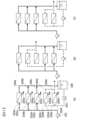
- FIG. 2 is a process diagram showing an example of a permeate multi-stage treatment facility in which the ratio of the membrane areas of the first stage (first stage) and second stage (second stage) in the multi-stage permeate treatment of the present invention is 2:1.
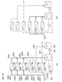
- FIG. 2 is a process diagram showing an example of a permeate multi-stage treatment facility in which the ratio of the membrane areas of the first stage (previous stage) and second stage (rear stage) in the permeate multi-stage treatment of the present invention is 3:2.
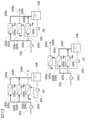
- the ratio of membrane areas of the first stage (first stage), second stage (second stage), and third stage (second stage) is 3:2:1.
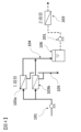
- FIG. 2 is a process diagram showing an example of a multi-stage permeate treatment facility. It is a process diagram showing an example of a general two-stage reverse osmosis membrane treatment device for permeated liquid.
- FIG. 3 is a process diagram for switching the supply side and concentration side of the reverse osmosis membrane treatment means when switching between the first stage and the second stage in the permeate multiple cutoff treatment of the present invention.
- the frequency of replacing the first stage membrane in such equipment is generally about six months to one year, or at most two years.
- the reverse osmosis membrane elements in the later stages (second and subsequent stages) further process the permeated liquid in the previous stage. It has been found that the membrane can be used for a longer period of time compared to the first stage), and that the second stage reverse osmosis membrane element, which has already been used, can be used as the first stage.
- the reverse osmosis membrane element is composed of a plurality of membranes in a pressure vessel, and it is difficult to remove it and configure it in another pressure vessel. Therefore, the present invention provides a multi-stage reverse osmosis membrane device for permeated liquid, which has a switching means for switching between the feed liquid pipe line and the permeated liquid pipe line of the reverse osmosis membrane treatment means in the front and rear stages. Thereby, an apparatus is provided in which the reverse osmosis membrane treatment means, which is a latter stage, can also be used as a former stage.
- the term "previous reverse osmosis membrane treatment means" refers to a reverse osmosis membrane device that performs multi-stage permeate treatment, which is the first stage treatment step when the device is introduced.
- Reverse osmosis membranes 103a to 103f in the figure represent individual reverse osmosis membrane treatment means.
- the reverse osmosis membrane treatment means there are pressure vessels loaded with multiple or one reverse osmosis membrane element. There may be multiple pressure vessels in series, or pressure vessels may be arranged in parallel and not installed in series.
- a stock solution is first supplied from the stock solution supply section and separated into a membrane permeate liquid and a concentrated liquid. The front stage is the first stage.
- the term "subsequent reverse osmosis membrane treatment means" refers to a reverse osmosis membrane device that performs multi-stage permeate treatment, which is the second stage and subsequent treatment steps when the device is introduced.
- the latter stage may be composed of two or three stages depending on the processing.
- the reverse osmosis membrane device can become a reverse osmosis membrane device capable of multi-stage treatment by arranging and connecting other reverse osmosis membrane devices afterwards.
- reverse osmosis membrane treatment means the equipment that performs the first reverse osmosis membrane treatment
- other equipment the equipment that performs the second and subsequent reverse osmosis membrane treatments on the obtained permeate
- reverse osmosis membrane treatment means the equipment that performs the first reverse osmosis membrane treatment
- reverse osmosis membrane treatment means the equipment that performs the second and subsequent reverse osmosis membrane treatments on the obtained permeate.
- the reverse osmosis membrane treatment means are shown by reverse osmosis membranes 103a, 103b, and 103c.
- the reverse osmosis membrane 103a is supplied with a stock solution, which is a liquid to be subjected to membrane separation, from a stock solution supply section (not shown) by a first-stage pump 102.
- the reverse osmosis membrane 103a includes a reverse osmosis membrane supply liquid pipe 102a (also simply referred to as a feed liquid pipe), a reverse osmosis membrane permeate pipe 104a (simply referred to as a permeate pipe), and a reverse osmosis membrane concentrate.
- a pipe line 105a (also simply referred to as a concentrate pipe line) is connected.
- a liquid to be treated is sent to the reverse osmosis membrane from the stock solution supplying section through a supply liquid pipe line, is processed by the reverse osmosis membrane, and flows out from the permeated liquid pipe line 104a and the concentrated liquid pipe line 105a.
- the reverse osmosis membrane 103a serves as a previous stage (first stage) reverse osmosis membrane treatment means in the present invention.
- the permeated liquid pipe 104a is connected to a first stage permeated liquid tank (second stage supplied liquid tank) 106, and the permeated liquid processed in the previous stage (first stage) is stored in the liquid tank.
- the reverse osmosis membrane 103b is connected in the same way as the reverse osmosis membrane 103a.
- the reverse osmosis membrane 103b also constitutes the front stage (first stage).
- the reverse osmosis membrane at the latter stage of the multi-stage process is the reverse osmosis membrane 103c, and liquid is sent from the first stage permeate tank 106 to the reverse osmosis membrane 103c by the second stage high pressure pump 206.
- a feed liquid line 102c, a permeated liquid line 104c, and a concentrated liquid line 105c are connected to the reverse osmosis membrane 103c.
- the reverse osmosis membrane device shown in FIG. 1 includes two reverse osmosis membranes 103a and 103b in the front stage where the stock solution is sent from the stock solution supply section, and one reverse osmosis membrane 10c in the back stage that processes the permeated liquid in the front stage. It is configured.
- the ratio of the membrane area of the front stage (first stage) and the rear stage (second stage) is 2:1, and the number of divisions in the front stage: n is 2, and the number of divisions in the rear stage: m is 1. .
- Each of the reverse osmosis membranes 103a to 103c is enclosed in a pressure vessel, and in the case of a reverse osmosis membrane, a plurality of reverse osmosis membrane elements or one reverse osmosis membrane element are enclosed in a pressure vessel in series, and there is only one pressure vessel.
- pressure vessels are arranged in series; in other cases, pressure vessels are arranged in parallel, and in other cases, pressure vessels are arranged in series. When they are arranged in series, the number of pressure vessels downstream is generally smaller, but there are cases where the number is the same.
- the reverse osmosis membranes 103a to 103c are updated to new reverse osmosis membranes 103a to 103c by replacing the constituent reverse osmosis membrane elements.
- the reverse osmosis membrane processing means is composed of reverse osmosis membranes 103a, 103b, and 103c, each of which is a plurality of reverse osmosis membrane processing sections, and each reverse osmosis membrane processing section has a It has a treated liquid supply port and a permeated liquid discharge port, and the treated liquid supply port and the permeated liquid discharge port are connected to the supply liquid pipe line or the permeated liquid pipe line so as to communicate individually for each reverse osmosis membrane processing section. has been done.
- it is possible to switch the passage for each reverse osmosis membrane processing section and for example, the passages of 103a and 103b that constitute the front stage can be changed separately.
- FIG. 1(c) the process after the reverse osmosis membranes 103a and 103b in the previous stage are replaced after operating the reverse osmosis membrane device will be described using FIG. 1(c).
- the reverse osmosis membrane element of the reverse osmosis membrane 103c has not been replaced, but has been used as a subsequent stage.
- the reverse osmosis membrane 103c which is the latter stage, is supplied with a stock solution, which is a liquid to be treated by membrane separation, from a stock solution supply section (not shown) by the pump 102 at the first stage.
- a stock solution which is a liquid to be treated by membrane separation
- the stock solution which is the liquid to be processed for membrane separation
- the stock solution supply unit Liquid is passed through by the first stage pump 102.
- the reverse osmosis membrane 103c which is the latter stage, the liquid to be treated is sent from the stock solution supply section through the feed liquid pipe line 102c, processed by the reverse osmosis membrane 103c, and then passed through the permeated liquid pipe line 104c and the concentrated liquid pipe line 105c. It flows out.
- the liquid is sent from the first-stage permeate tank 106 to the reverse osmosis membrane 103a by the second-stage high-pressure pump 206.
- the reverse osmosis membrane 103a at the front stage is connected to the permeate tank side by the supply liquid pipe line 102a at the front stage.
- the reverse osmosis membrane device of the present invention can switch between the following (1) and (2).
- the reverse osmosis membrane treatment means at the front and rear stages can be replaced.
- the permeate pipe line of the reverse osmosis membrane treatment means is connected to the feed liquid pipe side of the other reverse osmosis membrane treatment means.
- the reverse osmosis membrane processing means in the latter stage is connected to the stock solution supply section by switching the feed liquid pipe in the latter stage, and is connected to the permeate tank side by the permeate pipe in the latter stage.
- the reverse osmosis membrane treatment means at the front stage is connected to the permeate tank side by the supply liquid pipe line at the front stage.
- the reverse osmosis membrane elements used in the first stage and at least one subsequent stage of the multiple stages of reverse osmosis membrane elements are of the same type, and If the lifespan of a reverse osmosis membrane element is very short compared to normal, when replacing the first stage reverse osmosis membrane element, remove the reverse osmosis membrane element used in the first stage of multiple stages and replace it with The reverse osmosis membrane element used in the second and subsequent stages is used in the first stage, and new reverse osmosis membrane elements are used in the second and subsequent stages.
- elements of the same type refer to elements that desalinate up to 80% or more of the maximum amount of permeated water or 125% of the minimum amount of water under the same raw water quality, water temperature, operating pressure, and recovery rate. It refers to a reverse osmosis membrane element with a maximum rate of 99% or more, or a minimum rate of up to 101%. If the number of membrane elements in the first stage is insufficient, new membrane elements are also added to the first stage. This can be done by removing the second and subsequent reverse osmosis membrane elements from the pressure vessel and loading them into the pressure vessel of the first stage reverse osmosis membrane element, or by switching the valve or replacing the reverse osmosis membrane element without replacing the reverse osmosis membrane element. The equipment may be switched by switching piping and hoses, but it is preferable to switch by switching valves or by switching piping and hoses.
- multi-stage reverse osmosis treatment for permeate when the number of stages is more than two stages, for example, in the case of three-stage treatment, the reverse osmosis membrane elements in the second and third stages may be reused in the first stage.
- the third stage membrane element may be reused in the second stage, and only the second stage membrane element may be reused in the first stage.
- a valve is installed to switch the pipes, or the pipes and hoses are reconnected. Facilities for switching such as the above can be provided as permeate multi-stage reverse osmosis facilities.
- the permeated water supply port of the reverse osmosis membrane processing means or other reverse osmosis membrane processing means may be communicated with the liquid supply port to be treated by directly connecting a pipe, or as shown in FIGS. 1 to 3. Alternatively, it may be connected via a tank such as the first-stage permeate tank 106 or the second-stage permeate tank 206.
- FIGS. 1(a) to 1(c) are examples of equipment in which the ratio of the membrane areas of the first stage and the second stage is 2:1.
- the first stage is divided into n parts, here it is divided into two parts, and the second stage is divided into m parts, here it is divided into one part, and at the time of initial loading, 103a to 103e are In both cases, new reverse osmosis membrane elements are installed.
- FIG. 1(a) shows this initial flow. At this time, there is no particular restriction on the conduit line for the concentrated liquid, but generally in FIG. is supplied to a tank or pipe upstream of a high-pressure pump.
- the reverse osmosis membrane processing means at the front stage in FIG. 1 is divided into two sections 103a and 103b, and the reverse osmosis membrane processing means at the rear stage is not divided at 103c, but can be expressed as one division.
- the pressure vessels are arranged so that the same number of reverse osmosis membrane elements are loaded in each divided reverse osmosis membrane processing means.
- the inlet of the feed liquid pipeline 102b connected to the reverse osmosis membrane 103b is switched from the first-stage high-pressure pump 101 to the second-stage high-pressure pump 201 side.
- the inlet of the feed liquid pipeline 102c connected to the reverse osmosis membrane 103c is switched from the second stage high pressure pump 201 to the first stage high pressure pump 101 side.
- the permeate pipe line 104b is switched from the first-stage permeate tank 106 to discharge, and the permeate pipe 104c is switched from discharge to the first-stage permeate tank 106.
- the supply is switched so that it is supplied to a tank or pipe upstream of the high-pressure pump.
- the reverse osmosis membrane processing means at the front stage is divided into three parts of reverse osmosis membranes 103a to 103c, and the reverse osmosis membrane processing means at the latter stage is divided into three parts to 103d to 103e. It is divided into two parts. Furthermore, the pressure vessels are arranged so that the same number of reverse osmosis membrane elements are loaded in each divided reverse osmosis membrane processing means.
- the inlet of the permeate pipe 104a is switched from the first stage permeate tank 106 to discharge, and the permeate pipe 104b is switched from discharge to the first stage permeate tank 106. Switch to the side.
- the pipe line for the concentrated liquid there is no particular restriction on the pipe line for the concentrated liquid, but generally the pipe line 105a is connected to a tank or pipe line upstream of the high pressure pump 101 from the outlet, and the line 105b is connected to a tank upstream of the high pressure pump 101. Alternatively, it can be switched to discharging the concentrated liquid from the pipe. Here, the switching is made as shown in FIG. 1(b) to FIG. 1(c), but it is also possible to switch as shown in FIG. 1(a).
- the first-stage membrane element When switching as shown in Fig. 1(c), by returning from Fig. 1(c) to Fig. 1(a) at the time of the next exchange, when replacing the first-stage membrane element, the first-stage membrane element
- the membrane element used in the second stage membrane element can be used in part.
- the usable life of the membrane element in the first stage (first stage) is short, and the reverse osmosis membrane elements used in the later stages (second stage and later) have a long usable life because they are used at low concentrations. Even when the membrane element is reused as a reverse osmosis membrane element, there is no significant difference in the usable period as a first-stage membrane element. Therefore, the number of membrane elements to be replaced can be reduced by the number of membrane elements used in the second stage, and operating costs can be reduced.
- the period from immediately after the start of operation until half of the life of the reverse osmosis membrane refers to the period from immediately after the start of operation to half of the life of the reverse osmosis membrane, which refers to the period from immediately after the reverse osmosis membrane that has started to be used is started as a reverse osmosis membrane treatment means for the previous stage, for example, This was about half the time it took to replace the membrane treatment means.
- Equipment can be provided to make it easy to switch between the first and second stage reverse osmosis membranes, but it is also possible to remove the second and subsequent membrane elements and load them into the first stage. be.
- a tank is provided between the first and second stages, but it is also possible to connect the permeate pipe line of the first stage to the high-pressure pump of the second stage, or to It is also possible to increase the pressure and connect the first-stage permeate water pipe directly to the second-stage reverse osmosis membrane.
- the membrane area is determined by the number of reverse osmosis membrane processing units and reverse osmosis membrane elements, and in the present invention, the larger the number of divisions m and n, the smaller the membrane area around the divided reverse osmosis membrane.
- the larger the membrane area the smaller the required amount of permeation per unit area, and the pressure during permeation can be eased.
- the present invention is not limited to the case where the membrane area ratio is 2:1 between the first stage and the second stage, nor is it limited to the two-stage treatment of the permeate.
- Figure 2 shows an example in which the ratio of membrane areas in the first and second stages is 3:2 in two-stage permeate treatment
- Figure 3 shows an example in which the ratio of membrane areas in the first and second stages is 3:2 in three-stage permeate treatment.
- An example of the case where it is 1 is shown.
- the solid lines in the figure indicate the pipelines on the raw solution supply side and the first-stage high-pressure pump side
- the dotted lines indicate the pipelines on the permeate tank side and the second-stage pump side
- the dashed-dotted line indicates the pipelines for the second-stage permeate tank. Shows the piping on the side and third-stage pump side.
- the first stage is divided into n parts, here it is divided into three parts, and the second stage is divided into m parts, here it is divided into two parts.
- the reverse osmosis membranes 103a to 103c are operated as the front stage (first stage), and the reverse osmosis membranes 103d to e are operated as the rear stage (second stage).
- the reverse osmosis membrane element of the reverse osmosis membranes 103a to 103c used in the first stage is replaced. After that, as shown in FIG.
- the conduits of the reverse osmosis membranes 103b to 103c are switched and used as the second stage, and the reverse osmosis membranes 103d to 103e, which were used as the second stage, are replaced with the reverse osmosis membranes 103d to 103e, which are used as the first stage reverse osmosis membrane. Switch to and start operation.
- the first stage reverse osmosis membrane element reaches the end of its service life, the first stage membrane elements of the reverse osmosis membrane 103a and reverse osmosis membranes 103d to 103e are replaced, and as shown in FIG. 2(c), the reverse osmosis membrane element is replaced.
- the conduits of the membranes 103d to 103e are switched to use them as the second stage, and the reverse osmosis membranes 103b to 103c used as the second stage are switched to the first stage reverse osmosis membranes for operation.
- the concentrate pipes there are no particular restrictions on the concentrate pipes, but in general, in FIG. is switched to a tank or pipe located upstream of the After that, at the time of the above switching, the supply side pipe 102 is connected to the first stage high pressure pump 101, and the reverse osmosis membrane concentrate pipe is connected to the second stage high pressure pump 201, and the reverse osmosis membrane concentrate pipe is connected to the second stage high pressure pump 201.
- the pipe line is switched to a tank or pipe line upstream of the first-stage high-pressure pump 101.
- the first stage is divided into n parts, here it is divided into three parts
- the second stage is divided into m parts, here it is divided into three parts
- two of the divided parts in the second stage are used in the third stage.
- Two of the divided pieces are arranged.
- the reverse osmosis membranes 103a to 103c are operated as the first stage
- the reverse osmosis membranes 103d to e as the second stage
- the reverse osmosis membrane 103f as the third stage.
- the first stage membrane element deteriorates and reaches the end of its service life
- the first stage membrane element is replaced. Thereafter, as shown in FIG.
- the reverse osmosis membrane is operated with 103d to 103f as the first stage (first stage), 103a to b as the second stage (second stage), and 103f as the third stage (second stage).
- any one of 103a to 103c may be used as the third stage, and the remaining two become the second stage.
- one of the reverse osmosis membranes used as the first stage is used as the third stage, and the remaining two are used as the second stage.
- the three will form the first stage.
- the reference numerals are omitted in FIG. 3(b), they are the same as those in FIG. 3(a).
- the pipe line 105f is switched to a tank or pipe line upstream of the second-stage high-pressure pump 201.
- the supply side pipe 102 is connected to the high pressure pump 101, and the reverse osmosis membrane concentrate pipe is connected to the second stage high pressure pump 201, and the reverse osmosis membrane concentrate pipe is connected to the second stage high pressure pump 201.
- the reverse osmosis membrane processing means corresponding to the first stage in FIG.
- the reverse osmosis membrane treatment means which is the main part, is not divided, but can be expressed as one division.
- the pressure vessels are arranged so that each divided reverse osmosis membrane processing means is loaded with the same number of reverse osmosis membrane elements.
- the number of divisions m and the number of divisions n the number of divisions in the first stage, which is the previous stage, is m, and the number of divisions, which is the second stage and subsequent stages, is n.
- the switching means for the pipe line of the reverse osmosis membrane treatment means generally uses a valve such as a 2-way valve or 3-way valve, but the switching position is an L-shaped pipe, and the pipes are installed on both sides of the pipe. Switching may be performed by providing a connection means, or switching may be performed using a flexible joint such as a hose. For example, if 102a in Figure 1 extends from 12 o'clock toward 103a at 3 o'clock on a plane, and 102c extends from 6 o'clock toward 103c at 9 o'clock, then 102a in L-shaped piping 103a and 103c, and 102c can be connected to both 103a and 103c, allowing switching without using a valve. Connection can also be made perpendicularly or obliquely to the plane at this time.
- the reverse osmosis membrane processing means loaded with a new reverse osmosis membrane element has a higher flow rate of permeated water. Without adjusting the individual flow rates, the new reverse osmosis membrane element became fouled faster due to the slightly higher permeate flow rate, and the reverse osmosis membrane element used in the latter stage became fouled due to the dirt that had been present since the changeover.
- Example 1 Embodiments of the present invention will be described below based on FIGS. 2(a) to 2(c). Although the symbols in FIGS. 2(b) and 2(c) are omitted, they are the same as in FIG. 2(a).
- the ratio of the membrane area of the first stage and the second stage is 3:2, and the stock solution supplied is an approximately 1% solution of dimethylformamide (DMF), which is concentrated. This is then supplied as a solution of approximately 5% DMF to the subsequent distillation column for reuse.
- DMF dimethylformamide
- the DMF concentration of the first-stage permeate is approximately 0.2%, and the second-stage reverse osmosis membrane reduces this to 0.05% before supplying it to the wastewater treatment, and the concentrated fluid has a concentration of approximately 1%.
- the concentrated DMF is returned to the first stage inlet to improve the DMF recovery rate.
- the lifespan of the first stage reverse osmosis membrane element is approximately half a year, and the lifespan of the second stage reverse osmosis membrane element is approximately two years.
- new membrane elements are loaded into all of 103a to 103e.
- the reverse osmosis membrane elements are removed and new reverse osmosis membrane elements are loaded.
- the pipes are switched, and the three pipes 103a, 103d and e, which were used as the second stage, are used as the first stage, and the pipes 103b and c are used as the second stage.
- the first stage After replacing and switching the membrane elements mentioned above, the first stage will be operated with the membrane element that has been operated for half a year as the second stage and a new membrane element, but Since the deterioration of the reverse osmosis membrane due to operation is slight compared to the conditions of use in the first stage, the life of the membrane element remains the same as when the operation started, and the next time the first stage membrane element is replaced, it will take about six months. I will do it.
- the number of membrane elements to be replaced can be reduced by the amount of second-stage reverse osmosis membrane elements that are reused, and the overall operating cost can be reduced.
- the ratio of the membrane areas of the first stage and the second stage is 3:2, and the supplied stock solution is an approximately 1% solution of dimethylformamide (DMF), which is concentrated to approximately 5%.
- the DMF solution is supplied to the subsequent distillation column and reused.
- the DMF concentration of the first-stage permeate is approximately 0.2%, and the second-stage reverse osmosis membrane reduces this to 0.05% before supplying it to the wastewater treatment, and the concentrated fluid has a concentration of approximately 1%.
- the DMF concentrated to 100% was returned to the first stage inlet to improve the DMF recovery rate.
- there was no switching means so the reverse osmosis membrane element used in the second stage could not be loaded into the first stage.
- the life of the first stage reverse osmosis membrane element is about half a year, and the life of the second stage reverse osmosis membrane element is about two years.
- the present invention can be applied to permeate multi-stage reverse osmosis equipment that processes permeate in multiple stages.
- First-stage high-pressure pump 102a-f Reverse osmosis membrane supply liquid lines 103a-f: Reverse osmosis membranes 104a-f: Reverse osmosis membrane permeate lines 105a-f: Reverse osmosis membrane concentrate liquid lines 106:1 Stage permeate tank (second stage supply liquid tank) 201: 2nd stage high pressure pump 206: 2nd stage permeate tank (3rd stage supply liquid tank) 301: 3rd stage high pressure pump
Landscapes
- Chemical & Material Sciences (AREA)
- Engineering & Computer Science (AREA)
- Water Supply & Treatment (AREA)
- Chemical Kinetics & Catalysis (AREA)
- Nanotechnology (AREA)
- Separation Using Semi-Permeable Membranes (AREA)
Abstract
本発明の目的は、逆浸透膜の寿命が通常より短くなるような高濃度での有価物の濃縮を行い、さらに透過液を多段に透過させる透過液複数段逆浸透設備において、膜エレメントの交換本数を減らして運転コストを削減する逆浸透膜装置を提供することを目的とする。そのために、逆浸透膜処理手段で処理して得られた透過液をさらに逆浸透膜処理手段で処理する透過液複数段処理を行う逆浸透膜装置であって、前段および後段の逆浸透膜処理手段を切り替え可能とする切替手段を有する。 これにより、使用済みの前段の逆浸透膜処理手段の逆浸透膜エレメントを交換する際に、取り外す前記前段の逆浸透膜エレメントの代わりに、使用開始済みの後段以降の逆浸透膜処理手段の逆浸透膜エレメントの少なくとも一部を前記前段の逆浸透膜エレメントとして使用することができる逆浸透膜装置を提供する。
Description
本発明は、透過液複数段の逆浸透膜装置および逆浸透膜装置の運転方法に関するものである。
一般に有価物を含有する原液から、溶解した物質もしくは不純物を除去して回収する方法としては蒸留塔により液相と気相で分離して濃縮もしくはする方法や分離膜によりろ過、逆浸透を行う方法がある。蒸溜塔を用いる方法は、高濃度まで有価物の濃縮が可能であるが、液体を気体に変化させる必要があり、物質の潜熱のために多量の熱エネルギーを消費する。膜分離は相変化を伴わないため、蒸留塔より運転コストの低いプロセスであるが、膜の運転圧力の上限から蒸留塔のように高濃度まで濃縮できない。膜分離によりろ過することで、蒸留塔の前処理として有価物の濃度を上げる事ができ、気化させる液体の量を大きく減らすことができるため、膜分離と蒸留塔を併用した回収システムで効率を高めることが求められている。
一方、逆浸透膜を利用した膜分離の場合の運転コストは、浸透圧以上に圧力を掛けるためのポンプの電力費と、運転により劣化した逆浸透膜エレメントの交換費が大半を占め、膜分離による回収システムの効率化にはこれらのコスト削減が必要である。
回収する液体の濃度は、高ければ高いほど蒸留塔で蒸発させる液体が減るため、高度に濃縮することが求められ、それに伴い透過液の濃度も高くなる。透過液は水であれば再利用や放流のために透過水の濃度を下げる必要があり、透過液も回収して再利用する場合も、純度を高める必要がある。そのため図4に示すように、透過液を再度逆浸透膜に掛ける透過液複数段の設備を設置することが多い。
透過液に複数段の逆浸透膜設備を使用するために、逆浸透膜エレメントの使用本数はより多くなるため、逆浸透膜エレメントの交換本数を減らすことは運転コストの削減の観点では非常に有効である。
特許文献1には、回収における透過液複数段の逆浸透膜設備の膜の有効利用として、使用済みの逆浸透膜エレメント取り外し、別の装置に再利用することにより運転コストを削減すること開示されている。
透過液複数段の逆浸透膜設備に置いて、逆浸透膜エレメントの寿命は原液が高濃度になる1段目(前段ともいう)は数ヶ月~1年程度、低濃度になる2段目以降(後段ともいう)は1年~3年程度となることが多く、一般的に5年程度とされる海水淡水化や純水設備の膜寿命に比べ非常に短くなる。そのため、この膜交換費用、具体的に逆浸透膜エレメントを交換する数量を削減することが求められている。
特許文献1の交換した逆浸透膜エレメントの有効利用においては、再利用膜エレメントの利用先が問題となる。初期の使用先と再利用先の膜エレメントの使用数の不整合や、再利用膜エレメントを使用することによって起こる膜面への付着物の流入、再利用膜エレメントの利用に対する抵抗感などがあり、再利用は難しかった。
特許文献1の交換した逆浸透膜エレメントの有効利用においては、再利用膜エレメントの利用先が問題となる。初期の使用先と再利用先の膜エレメントの使用数の不整合や、再利用膜エレメントを使用することによって起こる膜面への付着物の流入、再利用膜エレメントの利用に対する抵抗感などがあり、再利用は難しかった。
すなわち、透過液を多段に透過させる透過液複数段逆浸透設備において、逆浸透膜エレメントの交換数を削減し、より少ない逆浸透膜エレメント数で有効な有価物の膜分離を持続運転できないという課題があった。本発明の目的は、逆浸透膜エレメントの交換数が削減される逆浸透膜装置およびその運転方法を提供することである。
上記課題を解決するため、逆浸透膜処理手段で処理して得られた透過液をさらに逆浸透膜処理手段で処理する透過液複数段処理を行う逆浸透膜装置において、使用した前段の逆浸透膜処理手段の逆浸透膜エレメントを交換する際に、使用していた後段の逆浸透膜エレメントを前段の逆浸透膜処理手段として利用することで、分離膜エレメントや膜の交換数を削減することができ、有効な有価物の膜分離を持続運転できる逆浸透膜装置を提供する。本発明の逆浸透膜装置は次の構成を有する。
逆浸透膜処理手段で処理して得られた透過液をさらに他の逆浸透膜処理手段で処理する透過液複数段処理を行うことができる逆浸透膜装置であって、前記逆浸透膜処理手段および前記他の逆浸透膜処理手段のそれぞれが供給液管路、透過液管路と濃縮液管路を有し、
以下の(1)、(2)いずれかの接続状態とするために前記供給液管路および前記透過液管路をそれぞれを切り替える切替手段と、前記切替手段を制御する切替制御手段とを備えることを特徴とする逆浸透膜装置である。
(1)前記逆浸透膜処理手段について、前記逆浸透膜処理手段の供給液管路が原液側に接続され、前記逆浸透膜処理手段の透過液管路が前記他の逆浸透膜処理手段の供給液管路側に接続される。
(2)前記他の逆浸透膜処理手段について、前記他の逆浸透膜処理手段の供給液管路が原液側に接続され、前記他の逆浸透処理手段の透過液管路が前記逆浸透膜処理手段の供給液管路側に接続される。
以下の(1)、(2)いずれかの接続状態とするために前記供給液管路および前記透過液管路をそれぞれを切り替える切替手段と、前記切替手段を制御する切替制御手段とを備えることを特徴とする逆浸透膜装置である。
(1)前記逆浸透膜処理手段について、前記逆浸透膜処理手段の供給液管路が原液側に接続され、前記逆浸透膜処理手段の透過液管路が前記他の逆浸透膜処理手段の供給液管路側に接続される。
(2)前記他の逆浸透膜処理手段について、前記他の逆浸透膜処理手段の供給液管路が原液側に接続され、前記他の逆浸透処理手段の透過液管路が前記逆浸透膜処理手段の供給液管路側に接続される。
また、前段の逆浸透膜処理手段と後段の逆浸透膜処理手段を有する透過液複数段処理を行う逆浸透膜装置であって、原液供給部と透過液槽とを少なくとも有し、前記前段の逆浸透膜処理手段および前記後段の逆浸透膜処理手段には供給液管路、透過液管路と濃縮液管路をそれぞれ備え、前記供給液管路および前記透過液管路の流路をそれぞれ切り替える切替手段を備え、以下の(1)または(2)の接続状態とすることにより前段と後段の逆浸透膜処理手段を切り替えることを特徴とする逆浸透膜装置である。
(1)前段の逆浸透膜処理手段は前段の供給液管路によって原液供給部側に接続され、前段の透過液管路によって透過液槽側に接続されており、後段の逆浸透膜処理手段は後段の供給液管路によって前記透過液槽側に接続される。
(2)後段の逆浸透膜処理手段は後段の供給液管路によって原液供給部側に接続され、後段の透過液管路によって透過液槽側に接続されており、前段の逆浸透膜処理手段は前段の供給液管路によって透過液槽側に接続される。
(1)前段の逆浸透膜処理手段は前段の供給液管路によって原液供給部側に接続され、前段の透過液管路によって透過液槽側に接続されており、後段の逆浸透膜処理手段は後段の供給液管路によって前記透過液槽側に接続される。
(2)後段の逆浸透膜処理手段は後段の供給液管路によって原液供給部側に接続され、後段の透過液管路によって透過液槽側に接続されており、前段の逆浸透膜処理手段は前段の供給液管路によって透過液槽側に接続される。
また、前記逆浸透膜処理手段または前記前段の逆浸透膜処理手段は、1以上の整数であるnで分割されたn個の逆浸透膜処理部を備え、前記他の逆浸透膜処理手段または前記後段の逆浸透膜処理手段は、1以上の整数であるmで分割されたm個の逆浸透膜処理部を備え、それぞれの複数の逆浸透膜処理部に被非処理液供給口と透過液排出口を有し、被処理液供給口と透過液排出口は前記供給液管路または前記透過液管路に逆浸透膜処理部毎に個別に連通されており、前記切替手段によってそれぞれの逆浸透膜処理部毎に切り替えることが可能な逆浸透膜装置を提供する。
さらに、前記前段のn個の逆浸透膜処理部と前記後段のm個の逆浸透膜処理部において、各逆浸透膜処理部には複数本の逆浸透膜エレメントを有し、nがm以上であって、前段のn個のうちの逆浸透膜処理部の一つと、後段のm個のうちの逆浸透膜処理部の一つに装填される逆浸透膜エレメントの本数が同じである逆浸透膜装置を提供する。
本発明の一形態は、逆浸透膜処理手段で処理して得られた透過液をさらに逆浸透膜処理手段で処理する透過液複数段処理を行う逆浸透膜装置の運転方法であって、使用済みの前段の逆浸透膜処理手段の逆浸透膜エレメントを交換する際に、取り外す前記前段の逆浸透膜エレメントの代わりに、使用開始済みの後段の逆浸透膜エレメントの少なくとも一部を前記前段の逆浸透膜エレメントとして使用する逆浸透膜装置の運転方法である。そのためには、前段の逆浸透膜処理手段と後段の逆浸透膜処理手段の配管路を切り替えて、後段の逆浸透膜処理手段を前段の逆浸透膜処理手段に簡便に切替可能な透過液複数段処理を行う逆浸透膜装置を提供する。
本発明の一形態は、取り外した前記前段の逆浸透膜エレメントの代わりに前記後段以降の逆浸透膜エレメントを使用する際に、使用開始済みの前記後段以降の逆浸透膜エレメントを前記前段の逆浸透膜エレメントとして再利用し、前記前段の逆浸透膜エレメントが後段の逆浸透膜エレメントより数が多い場合は未使用の逆浸透膜エレメントを追加し、前記後段以降は全て新しい逆浸透膜エレメント、もしくはより後段の使用開始済みの逆浸透膜エレメントと新しい逆浸透膜エレメントを使用する逆浸透膜装置の運転方法である。
本発明の一形態は、被処理液が有機溶剤を含む液体であり、前記逆浸透膜装置は前記被処理液中の有機溶剤を濃縮し、透過液から前記有機溶剤を取り除く処理を行うものである逆浸透膜装置の運転方法である。
本発明によれば、透過液を多段に透過させる透過液複数段逆浸透設備において、逆浸透膜エレメントの交換数を減らし、運転コストを削減することができる。つまり、より少ない逆浸透膜エレメント数で膜分離を持続運転することができる。特に、逆浸透膜エレメントの交換頻度が高くなる有価物の回収において、膜の交換本数を減らしてランニングコストを削減することができる。
本発明を実施する場合は一般的に、有機溶剤等の有価物回収や、汚れの多い排水再利用等で使用する事がより有効である。それらの設備での1段目の膜の交換頻度は半年から1年程度、長くても2年程度までが一般的である。すなわち、逆浸透膜処理装置は頻繁に膜を交換する必要があるが、本発明者らは後段(2段目以降)の逆浸透膜エレメントは前段の透過液をさらに処理するので、前段(1段目)と比較して膜を長時間使用することができ、使用開始済みの後段の逆浸透膜エレメントを前段として使用できることを見出した。しかしながら、逆浸透膜処理手段は圧力容器の中に逆浸透膜エレメントが複数の膜で構成されており、取り外して別の圧力容器内に構成することは困難である。そこで、本発明の透過液複数段の逆浸透膜装置は、前段と後段の逆浸透膜処理手段の供給液管路および前記透過液管路をそれぞれを切り替える切替手段を有する装置を提供する。これにより、後段であった逆浸透膜処理手段を前段としても使用可能な装置を提供する。
本発明の逆浸透膜装置について、図1を参照しつつ詳細を説明する。なお、本発明において「前段の逆浸透膜処理手段」とは、複数段の透過液処理を行う逆浸透膜装置において、装置導入時に第1段目の処理工程であるものをいう。図中の逆浸透膜103a~fは個々の逆浸透膜処理手段を示している。逆浸透膜処理手段の中には逆浸透膜エレメントを複数または1本装填した圧力容器があり、圧力容器は複数並列、さらにその並列の並びが直列に配置されている場合もあれば、圧力容器1本が直列に複数、もしくは圧力容器が並列に並び直列の設置は無い場合もある。第1段目の逆浸透膜処理手段は原液供給部から原液が最初に供給され膜透過液と濃縮液に分離される。前段は最初の1段目である。
本発明において「後段の逆浸透膜処理手段」とは、複数段の透過液処理を行う逆浸透膜装置において、装置導入時に第2段目以降の処理工程であるものをいう。後段は、2段でも3段でもよく処理に応じて多段で構成される。なお、逆浸透膜装置は、後付けで他の逆浸透膜装置を配置し接続することで、複数段処理が可能な逆浸透膜装置となり得る。この場合は、最初の逆浸透膜処理を行う装置を「逆浸透膜処理手段」と表し、得られた透過液をさらに他の装置で2段目以降の逆浸透膜処理を行う装置を「他の逆浸透膜処理手段」と表す。
図1(a)において、逆浸透膜処理手段は逆浸透膜103a、103b、103cで示される。逆浸透膜103aは、図示しない原液供給部から膜分離を行う被処理液である原液が1段目のポンプ102によって通液される。逆浸透膜103aには、逆浸透膜供給液管路102a(単に、供給液管路ともいう)と逆浸透膜透過液管路104a(単に、透過液管路ともいう)と逆浸透膜濃縮液管路105a(単に、濃縮液管路ともいう)が接続されている。逆浸透膜には、原液供給部側から供給液管路で被処理液が送られ、逆浸透膜にて処理されて、透過液管路104aと濃縮液管路105aから流れ出る。つまり、逆浸透膜103aは本発明において前段(1段目)の逆浸透膜処理手段となっている。透過液管路104aは透過液を1段目透過液槽(2段目供給液槽)106に接続されており、前段(1段目)で処理され透過液は液槽に貯められる。逆浸透膜103bは、逆浸透膜103aと同様に接続されている。逆浸透膜103bも前段(1段目)を構成している。図1(a)において、複数段の処理の後段の逆浸透膜は逆浸透膜103cであり、1段目透過液槽106から2段目高圧ポンプ206により逆浸透膜103cへ送液される。逆浸透膜103cには、供給液管路102cと透過液管路104cと濃縮液管路105cが接続されている。
図1の逆浸透膜装置は、原液供給部から原液が送られる前段は2つの逆浸透膜103aと103bにより構成され、前段で透過された透過液を処理する後段は1つの逆浸透膜10cで構成されている。この装置は、前段(1段目)と後段(2段目)の膜面積の比が2:1であり、前段の分割数:nは2、後段の分割数:mは1と表される。各逆浸透膜103a~cは、それぞれ圧力容器に封入されており、逆浸透膜は、複数本もしくは1本の逆浸透膜エレメントが直列に圧力容器に封入され、その圧力容器が1本の場合もあれば、圧力容器が直列に並ぶ場合もあり、また、圧力容器が並列にならび、さらに直列に配置されている場合もある。直列に配置されている場合は下流の方が圧力容器の数が少なくなっていく事が一般的ではあるが、同じ本数の場合もある。逆浸透膜103a~cは、使用後に、構成要素の逆浸透膜エレメントを交換することで、新しい逆浸透膜103a~cに更新される。
本発明の逆浸透膜装置は、逆浸透膜処理手段が、それぞれの複数の逆浸透膜処理部である逆浸透膜103a、103b、103cで構成され、それぞれの逆浸透膜処理部は、被非処理液供給口と透過液排出口を有し、被処理液供給口と透過液排出口は前記供給液管路または前記透過液管路に逆浸透膜処理部毎に個別に連通するように接続されている。ここで、本発明の逆浸透膜装置は、逆浸透膜処理部毎に通路を切り替えることが可能となっており、たとえば前段を構成する103aと103bが別々に通路を変更することができる。
続いて、逆浸透膜装置を運転後で、前段の逆浸透膜103aと103bを交換した後について、図1(c)を用いて説明する。なお、逆浸透膜103cの逆浸透膜エレメントは交換しておらず、後段として使用後のものである。最初に後段であった逆浸透膜103cは、図示しない原液供給部から膜分離を行う被処理液である原液が1段目のポンプ102によって通液される。図1の実施態様では前段の逆浸透膜処理部が2つ必要であるので、逆浸透膜エレメントを交換した逆浸透膜103bについても、原液供給部から膜分離を行う被処理液である原液が1段目のポンプ102によって通液される。後段であった逆浸透膜103cは、原液供給部側から供給液管路102cで被処理液が送られ、逆浸透膜103cにて処理されて、透過液管路104cと濃縮液管路105cから流れ出る。そして、1段目透過液槽106から2段目高圧ポンプ206により逆浸透膜103aへ送液される。前段の逆浸透膜103aは前段の供給液管路102aによって透過液槽側に接続される。
つまり、本発明の逆浸透膜装置は、次の(1)と(2)を切替え可能となっており。(1)と(2)を切替えることで、前段と後段の逆浸透膜処理手段を入れ替えることができる
(1)前記逆浸透膜処理手段について、前記逆浸透膜処理手段の供給液管路が原液側に接続され、前記逆浸透膜処理手段の透過液管路が前記他の逆浸透膜処理手段の供給液管路側に接続される。
(2)逆浸透膜処理手段は、後段の逆浸透膜処理手段は後段の供給液管路を切り替えることによって原液供給部側に接続され、後段の透過液管路によって透過液槽側に接続されており、前段の逆浸透膜処理手段は前段の供給液管路によって透過液槽側に接続される。
(1)前記逆浸透膜処理手段について、前記逆浸透膜処理手段の供給液管路が原液側に接続され、前記逆浸透膜処理手段の透過液管路が前記他の逆浸透膜処理手段の供給液管路側に接続される。
(2)逆浸透膜処理手段は、後段の逆浸透膜処理手段は後段の供給液管路を切り替えることによって原液供給部側に接続され、後段の透過液管路によって透過液槽側に接続されており、前段の逆浸透膜処理手段は前段の供給液管路によって透過液槽側に接続される。
また、本発明を実施する場合、前段と後段で使用する逆浸透膜エレメントは同一の品種を使用する事が一般的ではあるが、同一の運転圧、供給水濃度における透過性能、除去性能が±30%程度の近い性能の膜であれば異なる品種であっても適応可能であり、逆浸透膜エレメントの使用品種が廃番などで複数の逆浸透膜エレメントの品種が混在しても特に問題は無い。
透過液複数段処理を行う逆浸透膜装置で、複数段の逆浸透膜エレメントの1段目とそれ以降の少なくとも1つの段において使用する逆浸透膜エレメントが同種の物であり、1段目の逆浸透膜エレメントの寿命が通常に比べて非常に短い場合、1段目の逆浸透膜エレメントを交換する際に、複数段1段目に使用していた逆浸透膜エレメントを除去し、代わりに2段目以降に使用していた逆浸透膜エレメントを1段目に使用し、2段目以降に新しい逆浸透膜エレメントを使用する。ここで同種のエレメントとは、同一の原水水質、水温、運転圧、回収率において、透過水の水量が最大のものに対して80%以上、もしくは最小のものに対して125%まで、脱塩率が最大のものに対して99%以上、もしくは最小のものに対して101%までである逆浸透膜エレメントのことである。1段目の膜エレメントの本数が不足する場合は、新しい膜エレメントも1段目に追加する。これは2段目以降の逆浸透膜エレメントを圧力容器から取り外して1段目の逆浸透膜エレメントの圧力容器に装填してもよいし、逆浸透膜エレメントの入替を行わず、弁の切替や配管、ホースのつなぎ替えで切替る設備としてもよいが、弁の切替や配管、ホースのつなぎ替えで切替ることが好ましい。
透過液複数段逆浸透処理において、段数が2段よりも多い場合、例えば3段処理の場合に、2段目及び3段目の逆浸透膜エレメントを1段目に再使用しても良いし、3段目の膜エレメントは2段目で再使用して2段目の膜エレメントのみを1段目で再使用しても良い。
上記の交換を実現にするために、図1(a)~(c)の様に、透過液2段の逆浸透膜設備において、管路を切替る弁を設けるか、配管やホースをつなぎ替えるなどして切替る設備を透過液複数段逆浸透設備として設けることができる。
上記の交換を実現にするために、図1(a)~(c)の様に、透過液2段の逆浸透膜設備において、管路を切替る弁を設けるか、配管やホースをつなぎ替えるなどして切替る設備を透過液複数段逆浸透設備として設けることができる。
また、逆浸透膜処理手段や他の逆浸透膜処理手段の透過水供給口を被処理液供給口に連通させることは、直接管路を接続しても良いし、図1~図3のように、1段目透過液槽106や2段目透過液槽206のような槽を介して接続することとしても良い。
以下、本発明の逆浸透膜装置の運転方法について実施態様の例を手順を沿って説明する。図1(a)~(c)は1段目と2段目の膜面積の比率が2:1である場合の設備の一例である。図1(a)では、1段目はn分割、ここでは2個に分割されており、2段目はm分割、ここでは1個に分割されており、初期の装填時には103a~eにはいずれも新品の逆浸透膜エレメントを装填する。図1(a)はこの初期のフローを示す。この時、濃縮液の管路については特に制限は無いが、一般的に図1(a)において管路105a~bは濃縮液の払い出しを行う様に接続され、濃縮液の管路105cは101の高圧ポンプの上流に有る槽もしくは管路に供給される。
ここで、図1の前段に当たる逆浸透膜処理手段は103a~bの2分割されており、後段に当たる逆浸透膜処理手段は103cで分割されていないが、1分割と表現できる。そして、それぞれの分割された逆浸透膜処理手段は同じ数の逆浸透膜エレメントを装填する様に圧力容器が配されている。
運転開始後、103a~bの膜エレメントが寿命となり交換する時には、103a~bの膜エレメントを取り外し、新しい膜エレメントを装填する。この時、図1(b)のように以下の管路の切替を行う。
膜エレメントの交換を行った後に、逆浸透膜103bに接続された供給液管路102bの管路の入口を、1段目高圧ポンプ101から2段目高圧ポンプ201側に切替る。同時に逆浸透膜103cに接続された供給液管路102cの管路の入口を2段目高圧ポンプ201のから、1段目高圧ポンプ101側に切替る。透過液の管路については、透過液管路104bの管路を1段目透過液槽106から排出に切替、透過液管路104cの管路を排出から1段目透過液槽106に切替る。
濃縮液の管路については特に制限は無いが、一般的に図1(b)では濃縮液管路105a及び濃縮液105cは濃縮液の払い出しを行う様に切替られ、濃縮液管路105bは101の高圧ポンプの上流に有る槽もしくは管路に供給されるように切り替えられる。
逆浸透膜処理手段の分割数については、図3を参照すると、前段に当たる逆浸透膜処理手段は逆浸透膜103a~cの3分割されており、後段に当たる逆浸透膜処理手段は103d~eの2分割されている。さらに、それぞれの分割された逆浸透膜処理手段は同じ数の逆浸透膜エレメントを装填するように圧力容器が配されている。
図1(b)の103aと103cの1段目に使用されている逆浸透膜エレメントが劣化し、さらに次の交換を行う時には、103aと103cの逆浸透膜エレメントを取り外し、新しい膜エレメントを装填する。管路は図1(c)のように以下の切替を行う。膜エレメントの交換を行った後に、逆浸透膜103aに接続された供給液管路102aの管路の入口を、1段目高圧ポンプ101のから2段目高圧ポンプ201に切替る。同時に、逆浸透膜103bに接続された供給液管路102bの管路の入口を2段目高圧ポンプ201側のから、1段目高圧ポンプ101側に切替る。透過液の管路については、透過液管路104aの管路の入口を1段目透過液槽106のから排出に切替え、透過液管路104bの管路を排出から1段目透過液槽106側に切替る。
濃縮液の管路については特に制限は無いが、一般的に105aの管路は払い出しから101の高圧ポンプの上流に有る槽もしくは管路に、管路105bは101の高圧ポンプの上流に有る槽もしくは管路から濃縮液の払い出しを行う様に切り替えられる。ここで、図1(b)から図1(c)の様に切り替えたが、図1(a)の様に切替える事も可能である。図1(c)の様に切り替えた場合、さらに次の交換の時には図1(c)から図1(a)に戻ることにより、1段目の膜エレメントを交換する際に、1段目の一部に2段目の膜エレメントで使用した膜エレメントを使用する事ができる。
前段(1段目)の膜エレメントの使用可能期間は短く、後段以降(2段目以降)で使用した逆浸透膜エレメントは、低い濃度使用されるため、使用可能期間は長く、前段(1段目)の逆浸透膜エレメントとして再利用した場合においても、1段目膜エレメントとしての使用可能期間に大きな違いは無い。そのため、2段目に使用する膜エレメントの分だけ膜エレメントの交換本数を削減することができ、運転コストの低減を図ることができる。本発明において運転開始直後から逆浸透膜の寿命の半分までの間とは、使用開始済みの後段の逆浸透膜を前段の逆浸透膜処理手段として開始する直後から、たとえば前段に使用した逆浸透膜処理手段の交換までにかかった期間の半分の時期までの間である。
この1段目と2段目以降の逆浸透膜の切替が容易であるように設備を設けることもできるが、2段目以降の膜エレメントを一旦取り外し、1段目に装填することも可能である。また、図の例では1段目と2段目の間に槽を設けているが、1段目の透過液の管路を2段目の高圧ポンプに接続する、もしくは1段目の透過水の圧力を高くし、1段目の透過水の管路を直接2段目の逆浸透膜に接続することも可能である。
次に膜面積について説明する。膜面積は逆浸透膜処理部や逆浸透膜エレメントの本数で決定され、本発明では分割数m、nが大きければ分割された逆浸透膜辺りの膜面積が小さくなる。膜面積が大きいほど単位面積当たりの必要透過量が減り、透過する際の圧力を和らげることができる。膜面積の比率が1段目と2段目で2:1である場合に限らず、また、透過液2段処理に限らない。図2は透過液2段処理において1段目と2段目の膜面積の比率が3:2である場合の例を、図3には透過液3段処理で膜面積の比率が3:2:1である場合の例を示す。図中の実線の管路は原液供給側や1段目高圧ポンプ側の管路を示し、点線は透過液槽側や2段目ポンプ側の管路、一点鎖線はさらに2段目透過液槽側や3段目ポンプ側の管路を示す。
図2では1段目はn分割、ここでは3個に分割されており、2段目はm分割、ここでは2個に分割されている。運転の始めに103a~cの逆浸透膜を前段(1段目)として、103d~eの逆浸透膜を後段(2段目)として運転する。1段目の逆浸透膜エレメントが劣化して寿命となった際に、1段目に使用していた逆浸透膜103a~cの逆浸透膜エレメントを交換する。その後図2(b)の通り、逆浸透膜103b~cの管路を切替て2段目として使用し、2段目として使用していた逆浸透膜103d~eを1段目の逆浸透膜に切替て運転を行う。その次に1段目の逆浸透膜エレメントが寿命になった時には、逆浸透膜103aと逆浸透膜103d~eの1段目の膜エレメントを交換し、図2(c)の通り、逆浸透膜103d~eの管路を切替て2段目として使用し、2段目として使用していた逆浸透膜103b~cを1段目の逆浸透膜に切替て運転を行う。この時に2段目として使用する逆浸透膜を103aと、103d~eのいずれか1つとすることも可能である。
濃縮液の管路については特に制限は無いが、一般的に図2(a)では濃縮液管路105a~cの管路は払い出しに、濃縮液管路105d~eは1段目高圧ポンプ101の上流に有る槽もしくは管路に切り替えられる。その後は上記切替時に供給側の管路102が1段目高圧ポンプ101に接続される逆浸透膜の濃縮液管路が払い出しに、2段目高圧ポンプ201に接続される逆浸透膜の濃縮液管路が1段目高圧ポンプ101の上流に有る槽もしくは管路に切替られる。
図3では1段目はn分割、ここでは3個に分割されており、後段はm分割、ここでは3個に分割されており、2段目は分割されたうち2個が、3段目は分割されたうち2個が配されている。始めに103a~cの逆浸透膜を1段目として、103d~eの逆浸透膜を2段目として、103fの逆浸透膜を3段目として運転する。1段目の膜エレメントが劣化して寿命となった際に、まず1段目の膜エレメントを交換する。その後、図3(b)の様に103d~fを1段目(前段)として、103a~bを2段目(後段)、103fを3段目(後段)として逆浸透膜の運転を行う。2段目と3段目の逆浸透膜の切替においては、3段目は103a~cのいずれか1つで良く、残りの2つが2段目となる。この図3の場合は1段目として使用していた逆浸透膜の内、いずれか1つを3段目に、残りの2つが2段目となり、2段目と3段目として使用していた3つが1段目となる。この組み合わせは数が多く、いずれの組み合わせのいずれでも良い。図3(b)において、符号は省略しているが、図3(a)と同様である。
濃縮液の管路については特に制限は無いが、一般的に図3(a)では105a~cの管路は払い出しに、管路105d~eは101の高圧ポンプの上流に有る槽もしくは管路に、管路105fは201の2段目高圧ポンプの上流に有る槽もしくは管路に切り替えられる。その後は上記切替時に供給側の管路102が101の高圧ポンプに接続される逆浸透膜の濃縮液管路が払い出しに、201の2段目高圧ポンプに接続される逆浸透膜の濃縮液管路が101の高圧ポンプの上流に有る槽もしくは管路に、301の3段目高圧ポンプに接続される逆浸透膜の濃縮液管路が201の高圧ポンプの上流に有る槽もしくは管路に切替られる。
ここで、図3の前段に当たる逆浸透膜処理手段は103a~cの3分割されており、後段の2段目に当たる逆浸透膜処理手段は103d~eは2分割されており、後段で3段目となる逆浸透膜処理手段は分割されていないが、1分割と表現できる。ここでさらに、それぞれの分割された逆浸透膜処理手段は同じ数の逆浸透膜エレメントを装填する様に圧力容器が配されている。ただし、上述のように、分割数mと分割数nで表現する際には、前段である1段目の分割数をm個、後段である2段目以降の分割数をn個とする。
逆浸透膜処理手段の管路の切替手段は、2方弁や3方弁等の弁を使用する事が一般的であるが、切替の位置をLの字型の配管とし、その両側に配管の接続手段を設けて切替ても良いし、ホースなどのフレキシブルな継手を用いて切替てもよい。例えば、平面上で12時方向から図1の102aが3時方向にある103aに向かって伸びていて、6時方向から102cが9時方向にある103cがあれば、L字型の配管で102aから103aと103cのいずれにも接続することができ、102cからも103aと103cのいずれにも接続できるようになり、弁を使用しなくても切替が可能となる。この時の平面に対して垂直方向や斜めに対しても接続可能である。
また、逆浸透膜処理手段の切替を行う時には、図5のように逆浸透膜処理手段の供給側と濃縮側を入れ替えることも可能である。後段に使用されており、前段で再利用される逆浸透膜エレメントは膜の汚れは少ないが、汚れが全くないということは少なく、また供給側が濃縮側より汚れることが多いため、逆浸透膜処理手段内の流れを逆にすることにより汚れを排出できる。本特許の設備において供給側と濃縮側を入替て逆浸透膜処理手段の中の流れを逆にする場合、元々切替用の弁等の切替手段があるため、それを使用して切替を行うことができるため、追加となる配管部材等が少なく対応することができる利点がある。
また、上述のように後段の使用されていた逆浸透膜エレメントの汚れは前段に比べると非常に少ないとはいえ、汚れが全くないということは少ないため、全く同じ条件で切替後の運転を行った場合、新しい逆浸透膜エレメントを装填された逆浸透膜処理手段の方が透過水の流量が多くなる。そのまま個別の流量調節を行わず、新しい逆浸透膜エレメントが少し多くなった透過水流量のために汚れが早くなり、後段で使用されていた逆浸透膜エレメントが切替時から有る汚れのために汚れの進行が遅くなる事を利用して同じ汚れになるまでそのまま運転することも可能であるし、新しい逆浸透膜エレメントを使用した逆浸透膜処理手段の透過液流量よりも、後段で使用されていた逆浸透膜エレメントが装填された逆浸透膜処理手段の流量を低く調整し、新しい逆浸透膜エレメントの汚れが進んでいくにつれ徐々にもしくは汚れが進んだところで一度に個別の流量調整をやめることも可能である。
また、後段に使用していた逆浸透膜エレメントを前段で使用する場合、一般的に問題となる再利用膜エレメントに付着している物質が新たに使用する時に問題となる点は、前段に対してその透過水を処理していた逆浸透膜エレメントであるため、本出願では問題が無く利用可能であるが、薬品洗浄を行っても問題は無い。この薬品洗浄を行う場合であっても、本出願では切替手段によって逆浸透膜処理手段を切替るため、逆浸透膜エレメントの取り外し、再装填等は必要なく簡単に行う事が可能である。
(実施例1)
以下に本発明の実施形態を図2(a)~(c)を元に説明する。図2(b)と(c)の符号は省略しているが、図2(a)と同様である。図2の逆浸透膜装置は1段目と2段目の膜面積の比率が3:2であり、供給する原液はジメチルホルムアミド(DMF)の約1%の溶液であって、それを濃縮して約5%のDMFの溶液として、後段の蒸留塔に供給して再利用する。1段目の透過液のDMF濃度は、約0.2%であり、2段目の逆浸透膜ではこれを0.05%まで低下させて排液処理に供給し、濃縮液は約1%まで濃縮されたDMFを1段目の入口に戻し、DMFの回収率を向上させる。
以下に本発明の実施形態を図2(a)~(c)を元に説明する。図2(b)と(c)の符号は省略しているが、図2(a)と同様である。図2の逆浸透膜装置は1段目と2段目の膜面積の比率が3:2であり、供給する原液はジメチルホルムアミド(DMF)の約1%の溶液であって、それを濃縮して約5%のDMFの溶液として、後段の蒸留塔に供給して再利用する。1段目の透過液のDMF濃度は、約0.2%であり、2段目の逆浸透膜ではこれを0.05%まで低下させて排液処理に供給し、濃縮液は約1%まで濃縮されたDMFを1段目の入口に戻し、DMFの回収率を向上させる。
1段目の逆浸透膜エレメントの寿命は約半年であり、2段目の逆浸透膜エレメントの寿命は約2年である。運転開始時には103a~eのいずれにも新品の膜エレメントが装填される。半年後に1段目の103a~cの逆浸透膜エレメントの交換が必要となった時、その逆浸透膜エレメントを取り外し、新品の逆浸透膜エレメントを装填する。そして、管路を切替、103aと2段目として使用していた103dとeの3つを1段目とし、103bとcを2段目として使用する。
上記の膜エレメントの交換と切替を行った後、1段目は2段目として半年の運転を行った膜エレメントと新品の膜エレメントで運転を行う事になるが、2段目での半年の運転による逆浸透膜の劣化は、1段目の使用条件に対して軽微であるため、膜エレメントの寿命は運転開始時と変わらず、次回の1段目の膜エレメントの交換も、約半年後に行うこととなる。このような交換、切替を行うことにより、再利用される2段目の逆浸透膜エレメントの分、膜エレメントの交換本数が減って全体の運転コストを減らすことができる。
(比較例1)
実施例と同様1段目と2段目の膜面積の比率が3:2であり、供給する原液はジメチルホルムアミド(DMF)の約1%の溶液であって、それを濃縮して約5%のDMFの溶液として、後段の蒸留塔に供給して再利用する。1段目の透過液のDMF濃度は、約0.2%であり、2段目の逆浸透膜ではこれを0.05%まで低下させて排液処理に供給し、濃縮液は約1%まで濃縮されたDMFを1段目の入口に戻し、DMFの回収率を向上させた。実施例とは異なり切替手段がなかったため、2段目で使用していた逆浸透膜エレメントを1段目に装填できなかった。1段目の逆浸透膜エレメントの寿命は約半年であり、2段目の逆浸透膜エレメントの寿命は約2年である。
実施例と同様1段目と2段目の膜面積の比率が3:2であり、供給する原液はジメチルホルムアミド(DMF)の約1%の溶液であって、それを濃縮して約5%のDMFの溶液として、後段の蒸留塔に供給して再利用する。1段目の透過液のDMF濃度は、約0.2%であり、2段目の逆浸透膜ではこれを0.05%まで低下させて排液処理に供給し、濃縮液は約1%まで濃縮されたDMFを1段目の入口に戻し、DMFの回収率を向上させた。実施例とは異なり切替手段がなかったため、2段目で使用していた逆浸透膜エレメントを1段目に装填できなかった。1段目の逆浸透膜エレメントの寿命は約半年であり、2段目の逆浸透膜エレメントの寿命は約2年である。
図2(a)に示す逆浸透膜装置の運転開始時には103a~eのいずれにも新品の膜エレメントを装填した。半年後に1段目の103a~cの逆浸透膜エレメントの交換が必要となった時、その逆浸透膜エレメントを取り外し、新品の逆浸透膜エレメントを装填した。前段と後段の切り替えは行わなかった。このような交換を半年ごとに繰り返すと、2年目に2段目の逆浸透膜エレメントも交換の時期となった。この時は、1段目の103a~cと2段目の103d~eのすべての逆浸透膜エレメントを交換することとなり、実施例に対して2年間で103d~eの逆浸透膜エレメント分の交換膜の量が増えた。
本発明は、透過液を多段に処理する透過液複数段逆浸透設備に適用できる。
101:1段目高圧ポンプ
102a~f:逆浸透膜供給液管路
103a~f:逆浸透膜
104a~f:逆浸透膜透過液管路
105a~f:逆浸透膜濃縮液管路
106:1段目透過液槽(2段目供給液槽)
201:2段目高圧ポンプ
206:2段目透過液槽(3段目供給液槽)
301:3段目高圧ポンプ
102a~f:逆浸透膜供給液管路
103a~f:逆浸透膜
104a~f:逆浸透膜透過液管路
105a~f:逆浸透膜濃縮液管路
106:1段目透過液槽(2段目供給液槽)
201:2段目高圧ポンプ
206:2段目透過液槽(3段目供給液槽)
301:3段目高圧ポンプ
Claims (16)
- 逆浸透膜処理手段で処理して得られた透過液をさらに他の逆浸透膜処理手段で処理する透過液複数段処理を行うことができる逆浸透膜装置であって、
前記逆浸透膜処理手段および前記他の逆浸透膜処理手段のそれぞれが供給液管路、透過液管路と濃縮液管路を有し、
以下の(1)、(2)いずれかの接続状態とするために前記供給液管路および前記透過液管路をそれぞれを切り替える切替手段と、前記切替手段を制御する切替制御手段とを備えることを特徴とする逆浸透膜装置。
(1)前記逆浸透膜処理手段について、前記逆浸透膜処理手段の供給液管路が原液側に接続され、前記逆浸透膜処理手段の透過液管路が前記他の逆浸透膜処理手段の供給液管路側に接続される。
(2)前記他の逆浸透膜処理手段について、前記他の逆浸透膜処理手段の供給液管路が原液側に接続され、前記他の逆浸透処理手段の透過液管路が前記逆浸透膜処理手段の供給液管路側に接続される。 - 前段の逆浸透膜処理手段と後段の逆浸透膜処理手段を有する透過液複数段処理を行う逆浸透膜装置であって、原液供給部と透過液槽とを少なくとも有し、前記前段の逆浸透膜処理手段および前記後段の逆浸透膜処理手段には供給液管路、透過液管路と濃縮液管路をそれぞれ備え、前記供給液管路および前記透過液管路の流路をそれぞれ切り替える切替手段を備え、以下の(1)または(2)の接続状態とすることにより前段と後段の逆浸透膜処理手段を切り替えることを特徴とする逆浸透膜装置。
(1)前段の逆浸透膜処理手段は前段の供給液管路によって原液供給部側に接続され、前段の透過液管路によって透過液槽側に接続されており、後段の逆浸透膜処理手段は後段の供給液管路によって前記透過液槽側に接続される。
(2)後段の逆浸透膜処理手段は後段の供給液管路によって原液供給部側に接続され、後段の透過液管路によって透過液槽側に接続されており、前段の逆浸透膜処理手段は前段の供給液管路によって透過液槽側に接続される。 - 前記逆浸透膜処理手段または前記前段の逆浸透膜処理手段は、1以上の整数であるnで分割されたn個の逆浸透膜処理部を備え、前記他の逆浸透膜処理手段または前記後段の逆浸透膜処理手段は、1以上の整数であるmで分割されたm個の逆浸透膜処理部を備え、それぞれの複数の逆浸透膜処理部に被非処理液供給口と透過液排出口を有し、被処理液供給口と透過液排出口は前記供給液管路または前記透過液管路に逆浸透膜処理部毎に個別に連通されており、前記切替手段によってそれぞれの逆浸透膜処理部毎に切り替えられることを特徴とする、請求項1または2に記載の逆浸透膜装置。
- 前記前段のn個の逆浸透膜処理部と前記後段のm個の逆浸透膜処理部において、各逆浸透膜処理部には複数本の逆浸透膜エレメントを有し、nがm以上であって、前段のn個のうちの逆浸透膜処理部の一つと、後段のm個のうちの逆浸透膜処理部の一つに装填される逆浸透膜エレメントの本数が同じである、請求項3に記載の逆浸透膜装置。
- 前記供給液管路および前記透過液管路をそれぞれを切り替える切替手段が、回転可能なLの字型配管と、Lの字型をした配管の両端に設けられた接続手段とである請求項1~4のいずれかに記載の逆浸透膜装置。
- 前記供給液管路および前記透過液管路をそれぞれを切り替える切替手段が、前記他の逆浸透膜処理手段または後段の逆浸透膜処理手段への供給液管路が逆浸透膜の濃縮側に、濃縮液管路が逆浸透膜処理手段の供給側に接続され、逆浸透膜処理手段の通液方向を逆方向にすることができる、請求項1~5のいずれかに記載の逆浸透膜装置。
- 前記逆浸透膜手段または前記前段の逆浸透膜処理手段は、1以上の整数であるnで分割されたn個の逆浸透膜処理部を備え、前記他の逆浸透膜処理手段または前記後段の逆浸透膜処理手段1以上の整数であるmで分割されたm個の逆浸透膜処理部を備え、前記逆浸透膜処理部に用いる逆浸透膜エレメントが同一である請求項3に記載の逆浸透膜装置。
- 逆浸透膜処理手段で処理して得られた透過液をさらに逆浸透膜処理手段で処理する透過液複数段処理を行う逆浸透膜装置の運転方法であって、使用済みの前段の逆浸透膜処理手段の逆浸透膜エレメントを交換する際に、取り外す前記前段の逆浸透膜エレメントの代わりに、使用開始済みの後段以降の逆浸透膜処理手段の逆浸透膜エレメントの少なくとも一部を前記前段の逆浸透膜エレメントとして使用する逆浸透膜装置の運転方法。
- 取り外した前記前段の逆浸透膜エレメントの代わりに前記後段以降の逆浸透膜エレメントを使用する際に、使用開始済みの前記後段以降の逆浸透膜エレメントを前記前段の逆浸透膜エレメントとして再利用し、前記前段の逆浸透膜エレメントが後段の逆浸透膜エレメントより数が多い場合は未使用の逆浸透膜エレメントを追加し、前記後段以降は全て新しい逆浸透膜エレメント、もしくはより後段の使用開始済みの逆浸透膜エレメントと新しい逆浸透膜エレメントを使用する、請求項8に記載の逆浸透膜装置の運転方法。
- 前記逆浸透膜装置に通液される被処理液が有機溶剤を含む液体であり、前記逆浸透膜装置は前記被処理液中の有機溶剤を濃縮し、透過液から前記有機溶剤を取り除く処理を行う、請求項8または9に記載の逆浸透膜装置の運転方法。
- 使用開始済みの前記後段以降の逆浸透膜処理エレメントを前段の逆浸透膜処理に再利用することで前段と後段を切替える前に、少なくとも使用開始済みの後段の逆浸透膜エレメントの薬品洗浄を行う請求項8~10のいずれかに記載の逆浸透装置の運転方法。
- 請求項8~11のいずれかに記載された逆浸透膜装置の運転方法であって、前記後段から前段に切替られた逆浸透膜処理手段の透過液流量を、逆浸透膜が交換された逆浸透膜処理手段の透過液流量より下げて流量調節を行う逆浸透膜装置の運転方法。
- 前記後段から前段に切り替えられた逆浸透膜処理手段の透過液流量が、前記逆浸透膜が交換された逆浸透膜処理手段の透過液流量の50%から98%である請求項12に記載逆浸透膜装置の運転方法。
- 前記後段から前段に切替られた逆浸透膜処理手段の透過液流量と逆浸透膜が交換された逆浸透膜処理手段の透過液の流量を、運転開始直後から逆浸透膜の寿命の半分までの間に、徐々にまたは一度に、前記透過液流量調節を停止する請求項12または13に記載の逆浸透装置の運転方法。
- 少なくとも後段から前段に切替られる逆浸透膜処理手段において、逆浸透膜手段の供給側に濃縮液管路が接続され、逆浸透膜処理手段の濃縮側に供給側管路が接続されて、逆浸透膜処理手段の中の供給液から濃縮液への流れを逆方向とする請求項8~14のいずれかに記載の逆浸透膜処理装置の運転方法。
- 請求項1~7の逆浸透膜装置であって、前記前段の逆浸透膜処理手段の逆浸透膜の交換周期が2年以下である逆浸透膜装置。
Priority Applications (1)
| Application Number | Priority Date | Filing Date | Title |
|---|---|---|---|
| JP2023530576A JP7525067B2 (ja) | 2022-03-31 | 2023-03-30 | 逆浸透膜装置および逆浸透膜装置の運転方法 |
Applications Claiming Priority (2)
| Application Number | Priority Date | Filing Date | Title |
|---|---|---|---|
| JP2022058040 | 2022-03-31 | ||
| JP2022-058040 | 2022-03-31 |
Publications (1)
| Publication Number | Publication Date |
|---|---|
| WO2023190850A1 true WO2023190850A1 (ja) | 2023-10-05 |
Family
ID=88202875
Family Applications (1)
| Application Number | Title | Priority Date | Filing Date |
|---|---|---|---|
| PCT/JP2023/013144 Ceased WO2023190850A1 (ja) | 2022-03-31 | 2023-03-30 | 逆浸透膜装置および逆浸透膜装置の運転方法 |
Country Status (2)
| Country | Link |
|---|---|
| JP (1) | JP7525067B2 (ja) |
| WO (1) | WO2023190850A1 (ja) |
Cited By (1)
| Publication number | Priority date | Publication date | Assignee | Title |
|---|---|---|---|---|
| CN117582819A (zh) * | 2024-01-18 | 2024-02-23 | 伊春兆天生物科技有限公司 | 一种桦树提取汁液冷萃渗透分离设备及分离方法 |
Citations (3)
| Publication number | Priority date | Publication date | Assignee | Title |
|---|---|---|---|---|
| JP2003299936A (ja) * | 2002-02-08 | 2003-10-21 | Japan Organo Co Ltd | 逆浸透膜エレメントの再使用方法および回生逆浸透膜エレメント |
| WO2018182033A1 (ja) * | 2017-03-31 | 2018-10-04 | 東レ株式会社 | 造水方法及び造水装置 |
| WO2019188963A1 (ja) * | 2018-03-27 | 2019-10-03 | 野村マイクロ・サイエンス株式会社 | 超純水製造システム及び超純水製造システムの運転方法 |
-
2023
- 2023-03-30 JP JP2023530576A patent/JP7525067B2/ja active Active
- 2023-03-30 WO PCT/JP2023/013144 patent/WO2023190850A1/ja not_active Ceased
Patent Citations (3)
| Publication number | Priority date | Publication date | Assignee | Title |
|---|---|---|---|---|
| JP2003299936A (ja) * | 2002-02-08 | 2003-10-21 | Japan Organo Co Ltd | 逆浸透膜エレメントの再使用方法および回生逆浸透膜エレメント |
| WO2018182033A1 (ja) * | 2017-03-31 | 2018-10-04 | 東レ株式会社 | 造水方法及び造水装置 |
| WO2019188963A1 (ja) * | 2018-03-27 | 2019-10-03 | 野村マイクロ・サイエンス株式会社 | 超純水製造システム及び超純水製造システムの運転方法 |
Cited By (2)
| Publication number | Priority date | Publication date | Assignee | Title |
|---|---|---|---|---|
| CN117582819A (zh) * | 2024-01-18 | 2024-02-23 | 伊春兆天生物科技有限公司 | 一种桦树提取汁液冷萃渗透分离设备及分离方法 |
| CN117582819B (zh) * | 2024-01-18 | 2024-04-05 | 伊春兆天生物科技有限公司 | 一种桦树提取汁液冷萃渗透分离设备及分离方法 |
Also Published As
| Publication number | Publication date |
|---|---|
| JPWO2023190850A1 (ja) | 2023-10-05 |
| JP7525067B2 (ja) | 2024-07-30 |
Similar Documents
| Publication | Publication Date | Title |
|---|---|---|
| US20220203301A1 (en) | Apparatus and methods for solution processing | |
| JP6399895B2 (ja) | 逆浸透処理システムおよび逆浸透処理方法 | |
| US20180280888A1 (en) | Reverse osmosis treatment apparatus and reverse osmosis treatment method | |
| KR102818974B1 (ko) | 초순수 제조 시스템 및 초순수 제조 시스템의 운전 방법 | |
| US20200039846A1 (en) | Membrane filtration system with concentrate staging and concentrate recirculation, switchable stages, or both | |
| US20150144560A1 (en) | Separation membrane unit and method for using the same to produce fresh water | |
| WO2018150980A1 (ja) | 逆浸透処理装置及び逆浸透処理方法 | |
| WO2013002244A1 (ja) | 膜ろ過方法および膜ろ過装置 | |
| KR20150083048A (ko) | 역방향 교차운전을 이용한 알오 멤브레인 장치 및 이를 이용한 스케일 오염방지 방법 | |
| CN104736226B (zh) | 使用压力驱动膜实现高回收率脱盐 | |
| CN110520209A (zh) | 用于预防污垢的集成反渗透和膜清洁系统 | |
| JP7525067B2 (ja) | 逆浸透膜装置および逆浸透膜装置の運転方法 | |
| JP2017209654A (ja) | 逆浸透膜装置及び逆浸透膜装置の運転方法 | |
| JP7580911B2 (ja) | 濃縮システム | |
| JP2016022448A (ja) | 水処理装置及び水処理設備の洗浄方法 | |
| CN110215846A (zh) | 一种处理反渗透浓水用平板纳滤膜的清洗剂及清洗方法 | |
| JP2007000788A (ja) | 逆浸透膜を使用した水処理装置 | |
| JP7580912B2 (ja) | 濃縮システム | |
| JPWO2023190850A5 (ja) | ||
| CN113501567A (zh) | 一种多级串联反渗透膜组高盐废水浓缩系统及其浓缩方法 | |
| WO2017155463A1 (en) | Self-cleaning osmosis process, apparatus and system | |
| EP2218494B1 (en) | Method and device for the purification of an aqueous fluid | |
| KR102193618B1 (ko) | 바이오 파울링에 강하며 세정/역세정/수처리가 동시 가능한 역삼투 시스템 및 이를 이용한 수처리 방법 | |
| US9993774B2 (en) | Filtration system and filtration method | |
| JP2016022447A (ja) | 水処理装置及び水処理設備の洗浄方法 |
Legal Events
| Date | Code | Title | Description |
|---|---|---|---|
| WWE | Wipo information: entry into national phase |
Ref document number: 2023530576 Country of ref document: JP |
|
| 121 | Ep: the epo has been informed by wipo that ep was designated in this application |
Ref document number: 23780858 Country of ref document: EP Kind code of ref document: A1 |
|
| NENP | Non-entry into the national phase |
Ref country code: DE |
|
| 122 | Ep: pct application non-entry in european phase |
Ref document number: 23780858 Country of ref document: EP Kind code of ref document: A1 |