WO2023189732A1 - 環状シール材および製造方法 - Google Patents
環状シール材および製造方法 Download PDFInfo
- Publication number
- WO2023189732A1 WO2023189732A1 PCT/JP2023/010605 JP2023010605W WO2023189732A1 WO 2023189732 A1 WO2023189732 A1 WO 2023189732A1 JP 2023010605 W JP2023010605 W JP 2023010605W WO 2023189732 A1 WO2023189732 A1 WO 2023189732A1
- Authority
- WO
- WIPO (PCT)
- Prior art keywords
- sealing material
- annular sealing
- outer layer
- core
- rubber composition
- Prior art date
Links
- 239000003566 sealing material Substances 0.000 title claims abstract description 83
- 238000004519 manufacturing process Methods 0.000 title claims abstract description 24
- 229920001971 elastomer Polymers 0.000 claims description 87
- 239000005060 rubber Substances 0.000 claims description 86
- 239000000203 mixture Substances 0.000 claims description 72
- 238000000034 method Methods 0.000 claims description 37
- 229920006169 Perfluoroelastomer Polymers 0.000 claims description 34
- 238000000465 moulding Methods 0.000 claims description 28
- 229920001973 fluoroelastomer Polymers 0.000 claims description 19
- 239000003086 colorant Substances 0.000 claims description 15
- 239000011243 crosslinked material Substances 0.000 claims description 7
- 229920005560 fluorosilicone rubber Polymers 0.000 claims description 7
- 229920002379 silicone rubber Polymers 0.000 claims description 7
- 239000004945 silicone rubber Substances 0.000 claims description 6
- 238000001125 extrusion Methods 0.000 claims description 3
- 239000011162 core material Substances 0.000 description 65
- 238000004132 cross linking Methods 0.000 description 49
- 239000000049 pigment Substances 0.000 description 20
- 239000003431 cross linking reagent Substances 0.000 description 18
- 239000000047 product Substances 0.000 description 16
- -1 alkyl vinyl ether Chemical compound 0.000 description 15
- 229920001577 copolymer Polymers 0.000 description 15
- 239000000945 filler Substances 0.000 description 12
- 239000000178 monomer Substances 0.000 description 11
- BFKJFAAPBSQJPD-UHFFFAOYSA-N tetrafluoroethene Chemical group FC(F)=C(F)F BFKJFAAPBSQJPD-UHFFFAOYSA-N 0.000 description 10
- RAXXELZNTBOGNW-UHFFFAOYSA-N imidazole Natural products C1=CNC=N1 RAXXELZNTBOGNW-UHFFFAOYSA-N 0.000 description 9
- 238000004898 kneading Methods 0.000 description 9
- 239000000843 powder Substances 0.000 description 9
- 125000000524 functional group Chemical group 0.000 description 8
- 239000000463 material Substances 0.000 description 8
- 125000002560 nitrile group Chemical group 0.000 description 8
- 239000012860 organic pigment Substances 0.000 description 8
- 239000010409 thin film Substances 0.000 description 8
- 125000005843 halogen group Chemical group 0.000 description 7
- BQCIDUSAKPWEOX-UHFFFAOYSA-N 1,1-Difluoroethene Chemical compound FC(F)=C BQCIDUSAKPWEOX-UHFFFAOYSA-N 0.000 description 6
- 238000005520 cutting process Methods 0.000 description 6
- 150000002978 peroxides Chemical class 0.000 description 6
- RRZIJNVZMJUGTK-UHFFFAOYSA-N 1,1,2-trifluoro-2-(1,2,2-trifluoroethenoxy)ethene Chemical compound FC(F)=C(F)OC(F)=C(F)F RRZIJNVZMJUGTK-UHFFFAOYSA-N 0.000 description 5
- KOMNUTZXSVSERR-UHFFFAOYSA-N 1,3,5-tris(prop-2-enyl)-1,3,5-triazinane-2,4,6-trione Chemical compound C=CCN1C(=O)N(CC=C)C(=O)N(CC=C)C1=O KOMNUTZXSVSERR-UHFFFAOYSA-N 0.000 description 5
- VYPSYNLAJGMNEJ-UHFFFAOYSA-N Silicium dioxide Chemical compound O=[Si]=O VYPSYNLAJGMNEJ-UHFFFAOYSA-N 0.000 description 5
- 239000000654 additive Substances 0.000 description 5
- TZCXTZWJZNENPQ-UHFFFAOYSA-L barium sulfate Chemical compound [Ba+2].[O-]S([O-])(=O)=O TZCXTZWJZNENPQ-UHFFFAOYSA-L 0.000 description 5
- 229920001343 polytetrafluoroethylene Polymers 0.000 description 5
- 239000004810 polytetrafluoroethylene Substances 0.000 description 5
- 229920000459 Nitrile rubber Polymers 0.000 description 4
- 238000006243 chemical reaction Methods 0.000 description 4
- 238000010438 heat treatment Methods 0.000 description 4
- 239000001023 inorganic pigment Substances 0.000 description 4
- 229910052751 metal Inorganic materials 0.000 description 4
- 238000002156 mixing Methods 0.000 description 4
- BLTXWCKMNMYXEA-UHFFFAOYSA-N 1,1,2-trifluoro-2-(trifluoromethoxy)ethene Chemical compound FC(F)=C(F)OC(F)(F)F BLTXWCKMNMYXEA-UHFFFAOYSA-N 0.000 description 3
- UHOVQNZJYSORNB-UHFFFAOYSA-N Benzene Chemical compound C1=CC=CC=C1 UHOVQNZJYSORNB-UHFFFAOYSA-N 0.000 description 3
- CBENFWSGALASAD-UHFFFAOYSA-N Ozone Chemical compound [O-][O+]=O CBENFWSGALASAD-UHFFFAOYSA-N 0.000 description 3
- GWEVSGVZZGPLCZ-UHFFFAOYSA-N Titan oxide Chemical compound O=[Ti]=O GWEVSGVZZGPLCZ-UHFFFAOYSA-N 0.000 description 3
- XLOMVQKBTHCTTD-UHFFFAOYSA-N Zinc monoxide Chemical compound [Zn]=O XLOMVQKBTHCTTD-UHFFFAOYSA-N 0.000 description 3
- 239000013065 commercial product Substances 0.000 description 3
- 150000001875 compounds Chemical class 0.000 description 3
- 238000007731 hot pressing Methods 0.000 description 3
- JYEUMXHLPRZUAT-UHFFFAOYSA-N 1,2,3-triazine Chemical compound C1=CN=NN=C1 JYEUMXHLPRZUAT-UHFFFAOYSA-N 0.000 description 2
- VTYYLEPIZMXCLO-UHFFFAOYSA-L Calcium carbonate Chemical compound [Ca+2].[O-]C([O-])=O VTYYLEPIZMXCLO-UHFFFAOYSA-L 0.000 description 2
- 229920001780 ECTFE Polymers 0.000 description 2
- 229920002943 EPDM rubber Polymers 0.000 description 2
- 229920000181 Ethylene propylene rubber Polymers 0.000 description 2
- UQSXHKLRYXJYBZ-UHFFFAOYSA-N Iron oxide Chemical compound [Fe]=O UQSXHKLRYXJYBZ-UHFFFAOYSA-N 0.000 description 2
- ZCQWOFVYLHDMMC-UHFFFAOYSA-N Oxazole Chemical compound C1=COC=N1 ZCQWOFVYLHDMMC-UHFFFAOYSA-N 0.000 description 2
- 239000002033 PVDF binder Substances 0.000 description 2
- FZWLAAWBMGSTSO-UHFFFAOYSA-N Thiazole Chemical compound C1=CSC=N1 FZWLAAWBMGSTSO-UHFFFAOYSA-N 0.000 description 2
- 229920005549 butyl rubber Polymers 0.000 description 2
- 125000004432 carbon atom Chemical group C* 0.000 description 2
- 239000003795 chemical substances by application Substances 0.000 description 2
- 230000006835 compression Effects 0.000 description 2
- 238000007906 compression Methods 0.000 description 2
- 238000001816 cooling Methods 0.000 description 2
- 238000005336 cracking Methods 0.000 description 2
- 239000006185 dispersion Substances 0.000 description 2
- FJKIXWOMBXYWOQ-UHFFFAOYSA-N ethenoxyethane Chemical compound CCOC=C FJKIXWOMBXYWOQ-UHFFFAOYSA-N 0.000 description 2
- 229920000840 ethylene tetrafluoroethylene copolymer Polymers 0.000 description 2
- 229920006168 hydrated nitrile rubber Polymers 0.000 description 2
- 238000005304 joining Methods 0.000 description 2
- 238000002844 melting Methods 0.000 description 2
- 230000008018 melting Effects 0.000 description 2
- 239000008188 pellet Substances 0.000 description 2
- 229920002493 poly(chlorotrifluoroethylene) Polymers 0.000 description 2
- 239000005023 polychlorotrifluoroethylene (PCTFE) polymer Substances 0.000 description 2
- 229920002620 polyvinyl fluoride Polymers 0.000 description 2
- 229920002981 polyvinylidene fluoride Polymers 0.000 description 2
- 238000003825 pressing Methods 0.000 description 2
- QQONPFPTGQHPMA-UHFFFAOYSA-N propylene Natural products CC=C QQONPFPTGQHPMA-UHFFFAOYSA-N 0.000 description 2
- 150000003254 radicals Chemical class 0.000 description 2
- 229920005989 resin Polymers 0.000 description 2
- 239000011347 resin Substances 0.000 description 2
- 238000007665 sagging Methods 0.000 description 2
- 239000000377 silicon dioxide Substances 0.000 description 2
- 239000000126 substance Substances 0.000 description 2
- 229920005609 vinylidenefluoride/hexafluoropropylene copolymer Polymers 0.000 description 2
- 239000001052 yellow pigment Substances 0.000 description 2
- 239000011787 zinc oxide Substances 0.000 description 2
- 235000014692 zinc oxide Nutrition 0.000 description 2
- WRXCBRHBHGNNQA-UHFFFAOYSA-N (2,4-dichlorobenzoyl) 2,4-dichlorobenzenecarboperoxoate Chemical compound ClC1=CC(Cl)=CC=C1C(=O)OOC(=O)C1=CC=C(Cl)C=C1Cl WRXCBRHBHGNNQA-UHFFFAOYSA-N 0.000 description 1
- KDGNCLDCOVTOCS-UHFFFAOYSA-N (2-methylpropan-2-yl)oxy propan-2-yl carbonate Chemical compound CC(C)OC(=O)OOC(C)(C)C KDGNCLDCOVTOCS-UHFFFAOYSA-N 0.000 description 1
- RIPYNJLMMFGZSX-UHFFFAOYSA-N (5-benzoylperoxy-2,5-dimethylhexan-2-yl) benzenecarboperoxoate Chemical compound C=1C=CC=CC=1C(=O)OOC(C)(C)CCC(C)(C)OOC(=O)C1=CC=CC=C1 RIPYNJLMMFGZSX-UHFFFAOYSA-N 0.000 description 1
- KHXKESCWFMPTFT-UHFFFAOYSA-N 1,1,1,2,2,3,3-heptafluoro-3-(1,2,2-trifluoroethenoxy)propane Chemical compound FC(F)=C(F)OC(F)(F)C(F)(F)C(F)(F)F KHXKESCWFMPTFT-UHFFFAOYSA-N 0.000 description 1
- PEVRKKOYEFPFMN-UHFFFAOYSA-N 1,1,2,3,3,3-hexafluoroprop-1-ene;1,1,2,2-tetrafluoroethene Chemical group FC(F)=C(F)F.FC(F)=C(F)C(F)(F)F PEVRKKOYEFPFMN-UHFFFAOYSA-N 0.000 description 1
- RNFJDJUURJAICM-UHFFFAOYSA-N 2,2,4,4,6,6-hexaphenoxy-1,3,5-triaza-2$l^{5},4$l^{5},6$l^{5}-triphosphacyclohexa-1,3,5-triene Chemical compound N=1P(OC=2C=CC=CC=2)(OC=2C=CC=CC=2)=NP(OC=2C=CC=CC=2)(OC=2C=CC=CC=2)=NP=1(OC=1C=CC=CC=1)OC1=CC=CC=C1 RNFJDJUURJAICM-UHFFFAOYSA-N 0.000 description 1
- BJELTSYBAHKXRW-UHFFFAOYSA-N 2,4,6-triallyloxy-1,3,5-triazine Chemical compound C=CCOC1=NC(OCC=C)=NC(OCC=C)=N1 BJELTSYBAHKXRW-UHFFFAOYSA-N 0.000 description 1
- DMWVYCCGCQPJEA-UHFFFAOYSA-N 2,5-bis(tert-butylperoxy)-2,5-dimethylhexane Chemical compound CC(C)(C)OOC(C)(C)CCC(C)(C)OOC(C)(C)C DMWVYCCGCQPJEA-UHFFFAOYSA-N 0.000 description 1
- KECOIASOKMSRFT-UHFFFAOYSA-N 2-amino-4-(3-amino-4-hydroxyphenyl)sulfonylphenol Chemical compound C1=C(O)C(N)=CC(S(=O)(=O)C=2C=C(N)C(O)=CC=2)=C1 KECOIASOKMSRFT-UHFFFAOYSA-N 0.000 description 1
- MSTZGVRUOMBULC-UHFFFAOYSA-N 2-amino-4-[2-(3-amino-4-hydroxyphenyl)-1,1,1,3,3,3-hexafluoropropan-2-yl]phenol Chemical compound C1=C(O)C(N)=CC(C(C=2C=C(N)C(O)=CC=2)(C(F)(F)F)C(F)(F)F)=C1 MSTZGVRUOMBULC-UHFFFAOYSA-N 0.000 description 1
- HSTOKWSFWGCZMH-UHFFFAOYSA-N 3,3'-diaminobenzidine Chemical compound C1=C(N)C(N)=CC=C1C1=CC=C(N)C(N)=C1 HSTOKWSFWGCZMH-UHFFFAOYSA-N 0.000 description 1
- 239000004342 Benzoyl peroxide Substances 0.000 description 1
- OMPJBNCRMGITSC-UHFFFAOYSA-N Benzoylperoxide Chemical compound C=1C=CC=CC=1C(=O)OOC(=O)C1=CC=CC=C1 OMPJBNCRMGITSC-UHFFFAOYSA-N 0.000 description 1
- 229930185605 Bisphenol Natural products 0.000 description 1
- OKTJSMMVPCPJKN-UHFFFAOYSA-N Carbon Chemical compound [C] OKTJSMMVPCPJKN-UHFFFAOYSA-N 0.000 description 1
- 239000004641 Diallyl-phthalate Substances 0.000 description 1
- VGGSQFUCUMXWEO-UHFFFAOYSA-N Ethene Chemical compound C=C VGGSQFUCUMXWEO-UHFFFAOYSA-N 0.000 description 1
- 239000005977 Ethylene Substances 0.000 description 1
- 239000005909 Kieselgur Substances 0.000 description 1
- 239000006057 Non-nutritive feed additive Substances 0.000 description 1
- 229920001774 Perfluoroether Polymers 0.000 description 1
- NRCMAYZCPIVABH-UHFFFAOYSA-N Quinacridone Chemical compound N1C2=CC=CC=C2C(=O)C2=C1C=C1C(=O)C3=CC=CC=C3NC1=C2 NRCMAYZCPIVABH-UHFFFAOYSA-N 0.000 description 1
- 229910052581 Si3N4 Chemical group 0.000 description 1
- 239000006087 Silane Coupling Agent Substances 0.000 description 1
- 235000021355 Stearic acid Nutrition 0.000 description 1
- 229920006172 Tetrafluoroethylene propylene Polymers 0.000 description 1
- XSQUKJJJFZCRTK-UHFFFAOYSA-N Urea Chemical group NC(N)=O XSQUKJJJFZCRTK-UHFFFAOYSA-N 0.000 description 1
- QYKIQEUNHZKYBP-UHFFFAOYSA-N Vinyl ether Chemical group C=COC=C QYKIQEUNHZKYBP-UHFFFAOYSA-N 0.000 description 1
- YKTSYUJCYHOUJP-UHFFFAOYSA-N [O--].[Al+3].[Al+3].[O-][Si]([O-])([O-])[O-] Chemical compound [O--].[Al+3].[Al+3].[O-][Si]([O-])([O-])[O-] YKTSYUJCYHOUJP-UHFFFAOYSA-N 0.000 description 1
- 229920000800 acrylic rubber Polymers 0.000 description 1
- 230000000996 additive effect Effects 0.000 description 1
- 125000000217 alkyl group Chemical group 0.000 description 1
- WNROFYMDJYEPJX-UHFFFAOYSA-K aluminium hydroxide Chemical compound [OH-].[OH-].[OH-].[Al+3] WNROFYMDJYEPJX-UHFFFAOYSA-K 0.000 description 1
- PNEYBMLMFCGWSK-UHFFFAOYSA-N aluminium oxide Inorganic materials [O-2].[O-2].[O-2].[Al+3].[Al+3] PNEYBMLMFCGWSK-UHFFFAOYSA-N 0.000 description 1
- 125000003277 amino group Chemical group 0.000 description 1
- PYKYMHQGRFAEBM-UHFFFAOYSA-N anthraquinone Natural products CCC(=O)c1c(O)c2C(=O)C3C(C=CC=C3O)C(=O)c2cc1CC(=O)OC PYKYMHQGRFAEBM-UHFFFAOYSA-N 0.000 description 1
- 150000004056 anthraquinones Chemical class 0.000 description 1
- 230000003712 anti-aging effect Effects 0.000 description 1
- 239000003963 antioxidant agent Substances 0.000 description 1
- IRERQBUNZFJFGC-UHFFFAOYSA-L azure blue Chemical compound [Na+].[Na+].[Na+].[Na+].[Na+].[Na+].[Na+].[Na+].[Al+3].[Al+3].[Al+3].[Al+3].[Al+3].[Al+3].[S-]S[S-].[O-][Si]([O-])([O-])[O-].[O-][Si]([O-])([O-])[O-].[O-][Si]([O-])([O-])[O-].[O-][Si]([O-])([O-])[O-].[O-][Si]([O-])([O-])[O-].[O-][Si]([O-])([O-])[O-] IRERQBUNZFJFGC-UHFFFAOYSA-L 0.000 description 1
- 235000019400 benzoyl peroxide Nutrition 0.000 description 1
- NLNRQJQXCQVDQJ-UHFFFAOYSA-N bis(3,4-diaminophenyl)methanone Chemical compound C1=C(N)C(N)=CC=C1C(=O)C1=CC=C(N)C(N)=C1 NLNRQJQXCQVDQJ-UHFFFAOYSA-N 0.000 description 1
- QUDWYFHPNIMBFC-UHFFFAOYSA-N bis(prop-2-enyl) benzene-1,2-dicarboxylate Chemical compound C=CCOC(=O)C1=CC=CC=C1C(=O)OCC=C QUDWYFHPNIMBFC-UHFFFAOYSA-N 0.000 description 1
- HZTNYDWTDTYXQC-UHFFFAOYSA-N bis(prop-2-ynyl) benzene-1,4-dicarboxylate Chemical compound C#CCOC(=O)C1=CC=C(C(=O)OCC#C)C=C1 HZTNYDWTDTYXQC-UHFFFAOYSA-N 0.000 description 1
- IISBACLAFKSPIT-UHFFFAOYSA-N bisphenol A Chemical compound C=1C=C(O)C=CC=1C(C)(C)C1=CC=C(O)C=C1 IISBACLAFKSPIT-UHFFFAOYSA-N 0.000 description 1
- 239000001055 blue pigment Substances 0.000 description 1
- 229910000019 calcium carbonate Inorganic materials 0.000 description 1
- BRPQOXSCLDDYGP-UHFFFAOYSA-N calcium oxide Chemical compound [O-2].[Ca+2] BRPQOXSCLDDYGP-UHFFFAOYSA-N 0.000 description 1
- 239000000292 calcium oxide Substances 0.000 description 1
- ODINCKMPIJJUCX-UHFFFAOYSA-N calcium oxide Inorganic materials [Ca]=O ODINCKMPIJJUCX-UHFFFAOYSA-N 0.000 description 1
- 239000004202 carbamide Chemical group 0.000 description 1
- 239000006229 carbon black Substances 0.000 description 1
- CREMABGTGYGIQB-UHFFFAOYSA-N carbon carbon Chemical compound C.C CREMABGTGYGIQB-UHFFFAOYSA-N 0.000 description 1
- 239000011203 carbon fibre reinforced carbon Substances 0.000 description 1
- 125000002915 carbonyl group Chemical group [*:2]C([*:1])=O 0.000 description 1
- 239000003054 catalyst Substances 0.000 description 1
- 239000000919 ceramic Substances 0.000 description 1
- 239000004927 clay Substances 0.000 description 1
- 229910052570 clay Inorganic materials 0.000 description 1
- 238000005345 coagulation Methods 0.000 description 1
- 230000000254 damaging effect Effects 0.000 description 1
- LSXWFXONGKSEMY-UHFFFAOYSA-N di-tert-butyl peroxide Chemical compound CC(C)(C)OOC(C)(C)C LSXWFXONGKSEMY-UHFFFAOYSA-N 0.000 description 1
- PPSZHCXTGRHULJ-UHFFFAOYSA-N dioxazine Chemical compound O1ON=CC=C1 PPSZHCXTGRHULJ-UHFFFAOYSA-N 0.000 description 1
- 239000000806 elastomer Substances 0.000 description 1
- 238000010828 elution Methods 0.000 description 1
- 238000010556 emulsion polymerization method Methods 0.000 description 1
- 125000002573 ethenylidene group Chemical group [*]=C=C([H])[H] 0.000 description 1
- 239000003063 flame retardant Substances 0.000 description 1
- RMBPEFMHABBEKP-UHFFFAOYSA-N fluorene Chemical compound C1=CC=C2C3=C[CH]C=CC3=CC2=C1 RMBPEFMHABBEKP-UHFFFAOYSA-N 0.000 description 1
- 229910052731 fluorine Inorganic materials 0.000 description 1
- 125000001153 fluoro group Chemical group F* 0.000 description 1
- 239000011521 glass Substances 0.000 description 1
- 239000010439 graphite Substances 0.000 description 1
- 229910002804 graphite Inorganic materials 0.000 description 1
- 125000004435 hydrogen atom Chemical group [H]* 0.000 description 1
- 125000002887 hydroxy group Chemical group [H]O* 0.000 description 1
- 230000002401 inhibitory effect Effects 0.000 description 1
- DCYOBGZUOMKFPA-UHFFFAOYSA-N iron(2+);iron(3+);octadecacyanide Chemical compound [Fe+2].[Fe+2].[Fe+2].[Fe+3].[Fe+3].[Fe+3].[Fe+3].N#[C-].N#[C-].N#[C-].N#[C-].N#[C-].N#[C-].N#[C-].N#[C-].N#[C-].N#[C-].N#[C-].N#[C-].N#[C-].N#[C-].N#[C-].N#[C-].N#[C-].N#[C-] DCYOBGZUOMKFPA-UHFFFAOYSA-N 0.000 description 1
- PXZQEOJJUGGUIB-UHFFFAOYSA-N isoindolin-1-one Chemical compound C1=CC=C2C(=O)NCC2=C1 PXZQEOJJUGGUIB-UHFFFAOYSA-N 0.000 description 1
- GWVMLCQWXVFZCN-UHFFFAOYSA-N isoindoline Chemical compound C1=CC=C2CNCC2=C1 GWVMLCQWXVFZCN-UHFFFAOYSA-N 0.000 description 1
- 125000001449 isopropyl group Chemical group [H]C([H])([H])C([H])(*)C([H])([H])[H] 0.000 description 1
- 239000011133 lead Substances 0.000 description 1
- 239000007788 liquid Substances 0.000 description 1
- 239000000314 lubricant Substances 0.000 description 1
- ZLNQQNXFFQJAID-UHFFFAOYSA-L magnesium carbonate Chemical compound [Mg+2].[O-]C([O-])=O ZLNQQNXFFQJAID-UHFFFAOYSA-L 0.000 description 1
- 239000001095 magnesium carbonate Substances 0.000 description 1
- 229910000021 magnesium carbonate Inorganic materials 0.000 description 1
- 239000002184 metal Substances 0.000 description 1
- 239000010445 mica Substances 0.000 description 1
- 229910052618 mica group Inorganic materials 0.000 description 1
- 239000006082 mold release agent Substances 0.000 description 1
- NIHNNTQXNPWCJQ-UHFFFAOYSA-N o-biphenylenemethane Natural products C1=CC=C2CC3=CC=CC=C3C2=C1 NIHNNTQXNPWCJQ-UHFFFAOYSA-N 0.000 description 1
- QIQXTHQIDYTFRH-UHFFFAOYSA-N octadecanoic acid Chemical compound CCCCCCCCCCCCCCCCCC(O)=O QIQXTHQIDYTFRH-UHFFFAOYSA-N 0.000 description 1
- OQCDKBAXFALNLD-UHFFFAOYSA-N octadecanoic acid Natural products CCCCCCCC(C)CCCCCCCCC(O)=O OQCDKBAXFALNLD-UHFFFAOYSA-N 0.000 description 1
- 239000003921 oil Substances 0.000 description 1
- UJMWVICAENGCRF-UHFFFAOYSA-N oxygen difluoride Chemical class FOF UJMWVICAENGCRF-UHFFFAOYSA-N 0.000 description 1
- 238000012856 packing Methods 0.000 description 1
- 239000002245 particle Substances 0.000 description 1
- 125000005062 perfluorophenyl group Chemical group FC1=C(C(=C(C(=C1F)F)F)F)* 0.000 description 1
- 239000010702 perfluoropolyether Substances 0.000 description 1
- DGBWPZSGHAXYGK-UHFFFAOYSA-N perinone Chemical compound C12=NC3=CC=CC=C3N2C(=O)C2=CC=C3C4=C2C1=CC=C4C(=O)N1C2=CC=CC=C2N=C13 DGBWPZSGHAXYGK-UHFFFAOYSA-N 0.000 description 1
- 125000002080 perylenyl group Chemical group C1(=CC=C2C=CC=C3C4=CC=CC5=CC=CC(C1=C23)=C45)* 0.000 description 1
- CSHWQDPOILHKBI-UHFFFAOYSA-N peryrene Natural products C1=CC(C2=CC=CC=3C2=C2C=CC=3)=C3C2=CC=CC3=C1 CSHWQDPOILHKBI-UHFFFAOYSA-N 0.000 description 1
- 150000004714 phosphonium salts Chemical group 0.000 description 1
- IEQIEDJGQAUEQZ-UHFFFAOYSA-N phthalocyanine Chemical compound N1C(N=C2C3=CC=CC=C3C(N=C3C4=CC=CC=C4C(=N4)N3)=N2)=C(C=CC=C2)C2=C1N=C1C2=CC=CC=C2C4=N1 IEQIEDJGQAUEQZ-UHFFFAOYSA-N 0.000 description 1
- 230000000704 physical effect Effects 0.000 description 1
- 239000004014 plasticizer Substances 0.000 description 1
- 229920000058 polyacrylate Polymers 0.000 description 1
- 229920000768 polyamine Polymers 0.000 description 1
- 125000003367 polycyclic group Chemical group 0.000 description 1
- 229920005862 polyol Polymers 0.000 description 1
- 150000003077 polyols Chemical class 0.000 description 1
- 238000001556 precipitation Methods 0.000 description 1
- 238000002360 preparation method Methods 0.000 description 1
- 229960003351 prussian blue Drugs 0.000 description 1
- 239000013225 prussian blue Substances 0.000 description 1
- FYNROBRQIVCIQF-UHFFFAOYSA-N pyrrolo[3,2-b]pyrrole-5,6-dione Chemical compound C1=CN=C2C(=O)C(=O)N=C21 FYNROBRQIVCIQF-UHFFFAOYSA-N 0.000 description 1
- 150000003242 quaternary ammonium salts Chemical group 0.000 description 1
- IZMJMCDDWKSTTK-UHFFFAOYSA-N quinoline yellow Chemical compound C1=CC=CC2=NC(C3C(C4=CC=CC=C4C3=O)=O)=CC=C21 IZMJMCDDWKSTTK-UHFFFAOYSA-N 0.000 description 1
- 230000009257 reactivity Effects 0.000 description 1
- 239000001054 red pigment Substances 0.000 description 1
- 150000003839 salts Chemical class 0.000 description 1
- 239000004065 semiconductor Substances 0.000 description 1
- HQVNEWCFYHHQES-UHFFFAOYSA-N silicon nitride Chemical group N12[Si]34N5[Si]62N3[Si]51N64 HQVNEWCFYHHQES-UHFFFAOYSA-N 0.000 description 1
- 239000003381 stabilizer Substances 0.000 description 1
- 239000008117 stearic acid Substances 0.000 description 1
- 238000005728 strengthening Methods 0.000 description 1
- 239000000454 talc Substances 0.000 description 1
- 229910052623 talc Inorganic materials 0.000 description 1
- MHSKRLJMQQNJNC-UHFFFAOYSA-N terephthalamide Chemical compound NC(=O)C1=CC=C(C(N)=O)C=C1 MHSKRLJMQQNJNC-UHFFFAOYSA-N 0.000 description 1
- 229920001169 thermoplastic Polymers 0.000 description 1
- 239000004416 thermosoftening plastic Substances 0.000 description 1
- JOUDBUYBGJYFFP-FOCLMDBBSA-N thioindigo Chemical compound S\1C2=CC=CC=C2C(=O)C/1=C1/C(=O)C2=CC=CC=C2S1 JOUDBUYBGJYFFP-FOCLMDBBSA-N 0.000 description 1
- 239000004408 titanium dioxide Substances 0.000 description 1
- OGIDPMRJRNCKJF-UHFFFAOYSA-N titanium oxide Inorganic materials [Ti]=O OGIDPMRJRNCKJF-UHFFFAOYSA-N 0.000 description 1
- GRPURDFRFHUDSP-UHFFFAOYSA-N tris(prop-2-enyl) benzene-1,2,4-tricarboxylate Chemical compound C=CCOC(=O)C1=CC=C(C(=O)OCC=C)C(C(=O)OCC=C)=C1 GRPURDFRFHUDSP-UHFFFAOYSA-N 0.000 description 1
- 235000013799 ultramarine blue Nutrition 0.000 description 1
- 238000004073 vulcanization Methods 0.000 description 1
- NDKWCCLKSWNDBG-UHFFFAOYSA-N zinc;dioxido(dioxo)chromium Chemical compound [Zn+2].[O-][Cr]([O-])(=O)=O NDKWCCLKSWNDBG-UHFFFAOYSA-N 0.000 description 1
Images


Classifications
-
- B—PERFORMING OPERATIONS; TRANSPORTING
- B29—WORKING OF PLASTICS; WORKING OF SUBSTANCES IN A PLASTIC STATE IN GENERAL
- B29C—SHAPING OR JOINING OF PLASTICS; SHAPING OF MATERIAL IN A PLASTIC STATE, NOT OTHERWISE PROVIDED FOR; AFTER-TREATMENT OF THE SHAPED PRODUCTS, e.g. REPAIRING
- B29C69/00—Combinations of shaping techniques not provided for in a single one of main groups B29C39/00 - B29C67/00, e.g. associations of moulding and joining techniques; Apparatus therefore
- B29C69/02—Combinations of shaping techniques not provided for in a single one of main groups B29C39/00 - B29C67/00, e.g. associations of moulding and joining techniques; Apparatus therefore of moulding techniques only
-
- F—MECHANICAL ENGINEERING; LIGHTING; HEATING; WEAPONS; BLASTING
- F16—ENGINEERING ELEMENTS AND UNITS; GENERAL MEASURES FOR PRODUCING AND MAINTAINING EFFECTIVE FUNCTIONING OF MACHINES OR INSTALLATIONS; THERMAL INSULATION IN GENERAL
- F16J—PISTONS; CYLINDERS; SEALINGS
- F16J15/00—Sealings
- F16J15/02—Sealings between relatively-stationary surfaces
- F16J15/06—Sealings between relatively-stationary surfaces with solid packing compressed between sealing surfaces
- F16J15/10—Sealings between relatively-stationary surfaces with solid packing compressed between sealing surfaces with non-metallic packing
-
- F—MECHANICAL ENGINEERING; LIGHTING; HEATING; WEAPONS; BLASTING
- F16—ENGINEERING ELEMENTS AND UNITS; GENERAL MEASURES FOR PRODUCING AND MAINTAINING EFFECTIVE FUNCTIONING OF MACHINES OR INSTALLATIONS; THERMAL INSULATION IN GENERAL
- F16J—PISTONS; CYLINDERS; SEALINGS
- F16J15/00—Sealings
- F16J15/16—Sealings between relatively-moving surfaces
- F16J15/32—Sealings between relatively-moving surfaces with elastic sealings, e.g. O-rings
- F16J15/328—Manufacturing methods specially adapted for elastic sealings
-
- F—MECHANICAL ENGINEERING; LIGHTING; HEATING; WEAPONS; BLASTING
- F16—ENGINEERING ELEMENTS AND UNITS; GENERAL MEASURES FOR PRODUCING AND MAINTAINING EFFECTIVE FUNCTIONING OF MACHINES OR INSTALLATIONS; THERMAL INSULATION IN GENERAL
- F16J—PISTONS; CYLINDERS; SEALINGS
- F16J15/00—Sealings
- F16J15/16—Sealings between relatively-moving surfaces
- F16J15/32—Sealings between relatively-moving surfaces with elastic sealings, e.g. O-rings
- F16J15/3284—Sealings between relatively-moving surfaces with elastic sealings, e.g. O-rings characterised by their structure; Selection of materials
Definitions
- the present invention relates to an annular sealing material, and further relates to a method for manufacturing the same.
- sealing materials such as gaskets and packing used for various purposes
- a method is known in which the material is placed in a mold and manufactured by hot press molding (Japanese Patent Application Laid-Open No. 08-151450).
- An annular sealing material manufactured by hot press molding often has a linear parting line formed on the surface along the seam of the mold. Attachment of the annular sealing material to a device or the like may be performed accurately and easily by visually checking whether the parting line is twisted or sagging. However, it is desirable that the parting line be as small as possible from the viewpoint of ensuring airtightness when the annular sealing material is attached to a device or the like, and it may be difficult to visually recognize the parting line.
- An object of the present invention is to provide an annular sealing material having a parting line with improved visibility and a method for manufacturing the same.
- the present invention provides the following annular sealing material and its manufacturing method.
- An annular sealing material including a core and an outer layer surrounding the core, the annular sealing material having parting lines on an outer diameter side and an inner diameter side, the annular sealing material comprising: An annular sealing material, wherein the thickness of at least a part of the outer layer in the part where the parting line exists is smaller than the thickness of the outer layer in the part where the parting line does not exist.
- the annular sealing material according to claim 1, wherein the ratio of the thickness of a portion of the outer layer where the parting line is not present to the thickness of the portion where the parting line is present is 1.05 to 40.
- the outer layer contains at least one crosslinked material selected from the group consisting of perfluoroelastomer and fluororubber, and the core contains at least one crosslinked material selected from the group consisting of perfluoroelastomer, fluororubber, silicone rubber, and fluorosilicone rubber.
- annular sealing material having a parting line with improved visibility and a method for manufacturing the same.
- FIG. 3 is a schematic cross-sectional view in the circumferential direction of the annular sealing material, illustrating one step of the method for manufacturing the annular sealing material.
- FIG. 6 is a schematic cross-sectional view in the circumferential direction of the annular sealing material, illustrating another step of the method for manufacturing the annular sealing material.
- FIG. 7 is a schematic cross-sectional view in the circumferential direction of the annular sealing material, illustrating yet another step of the method for manufacturing the annular sealing material.
- the annular sealing material of the present invention includes a core and an outer layer that covers the core, has parting lines on the outer diameter side and the inner diameter side, and has parting lines on at least a part of the part where the parting lines are present. It is characterized in that the thickness is smaller than the thickness of the outer layer in the part where there is no parting line.
- FIG. 1(a) shows the shape of the annular sealing material in a plan view.
- the annular sealing material 1 is shown by diagonal lines.
- the annular sealing material 1 has an outer diameter D1 that is the diameter of the outer periphery and an inner diameter D2 that is the diameter of the inner periphery.
- the outer circumference and the inner circumference are the outer and inner circumferences of the annular sealing material 1, respectively, in a plan view.
- Planar view refers to viewing from the thickness direction of the annular sealing material 1.
- FIGS. 1(b) and 1(c) show cross-sectional views of the annular sealing material 1 perpendicular to the plane.
- the annular sealing material 1 includes a core 2 and an outer layer 3 that covers the periphery of the core 2. As shown in FIG. 1(a), the annular sealing material 1 preferably has a circular cross-sectional shape, but may have other cross-sectional shapes depending on the application.
- the annular sealing material 1 has a cross-sectional diameter (diameter) D3 and an outer layer 3 has a thickness T.
- the annular sealing material 1 has parting lines on the outer diameter side and the inner diameter side.
- the parting line can be a mark of a seam between two molds or a mark of removing burrs, which is generated on the surface of the outer layer 3 during the hot press molding process.
- the annular sealing material 1 has a parting line formed on the surface of the outer layer 3 along the outer circumference and the inner circumference.
- the parting line may be formed to be outwardly convex in the cross section of the annular sealing material 1.
- the thickness T1 of at least a portion of the outer layer 3 where the parting line exists is smaller than the thickness T2 of the portion where the parting line does not exist. Since the thickness T1 of at least part of the part of the outer layer 3 where the parting line exists is smaller than the thickness T2 of the part where the parting line does not exist, the core 2 is easily visible through the outer layer 3 on the parting line. Therefore, the visibility of the parting line tends to improve.
- the outer layer 3 of the annular sealing material 1 may have the thickness T1 in a part of the part where the parting line exists, or may have the thickness T1 in the entire part where the parting line exists.
- the ratio T2/T1 of the thickness T2 of the part where the parting line does not exist to the thickness T1 of the part where the parting line exists in the outer layer 3 is 1.05 to 40, and the core 2 is easily recognized through the outer layer 3. From this point of view, it is preferably 1.2 to 20.
- the core 2 preferably contains a coloring agent.
- the outer layer 3 may or may not contain a colorant.
- the outer layer 3 contains a colorant, it is preferable that the outer layer 3 contains a colorant different from the colorant contained in the core 2. It is more preferable that the outer layer 3 does not contain a colorant from the viewpoint of visibility of the core 2 (parting line).
- the annular sealing material 1 preferably has an average ratio (hereinafter also referred to as average ratio) of the thickness T of the outer layer 3 to the diameter D3 of the cross section from the viewpoint of reducing material costs, for example, from 1/35 to 1/4, Preferably it is 1/20 or more and 1/5 or less.
- the average ratio is the average of the ratios measured at five randomly selected cross sections of the annular sealing material 1. The ratio is expressed as, for example, the ratio T/D3 between the maximum thickness T of the outer layer 3 in the cross section of the annular sealing material 1 and the diameter D3 of the cross section including that thickness.
- the thickness T of the outer layer 3 and the thickness T2 of the part where no parting line exists may be, for example, 0.3 mm or more and 10 mm or less, and preferably 0.5 mm or more and 3 mm or less.
- the thickness T1 of the portion of the outer layer 3 where the parting line exists may be, for example, 0.1 mm or more and 5 mm or less, and preferably 0.2 mm or more and 1.5 mm or less.
- the diameter D3 of the cross section of the annular sealing material 1 may be, for example, 3 mm or more and 50 mm or less, and preferably 3 mm or more and 15 mm or less.
- the core 2 and the outer layer 3 can contain a crosslinked product of a crosslinkable rubber composition.
- the crosslinkable rubber composition forming the core 2 will be referred to as the crosslinkable rubber composition for the core
- the crosslinkable rubber composition forming the outer layer 3 will be referred to as the crosslinkable rubber composition for the outer layer and the crosslinkable rubber composition for the core.
- a crosslinkable rubber composition for an outer layer it is also referred to as a crosslinkable rubber composition.
- the crosslinkable rubber composition can contain a crosslinkable rubber component.
- the crosslinkable rubber component can form an elastomer (crosslinked rubber) having a crosslinked structure through a crosslinking reaction.
- the crosslinkable rubber component can have crosslinkable sites such as carbon-carbon unsaturated groups, nitrile groups, hydroxyl groups, amino groups, carbonyl groups, and halogen groups.
- crosslinkable rubber components include perfluoroelastomer (FFKM), fluororubber (FKM), silicone rubber, fluorosilicone rubber, ethylene-propylene rubber (EPM), ethylene-propylene-diene rubber (EPDM), and nitrile rubber (NBR). ; acrylonitrile butadiene rubber), hydrogenated nitrile rubber (HNBR; hydrogenated acrylonitrile butadiene rubber), butyl rubber (IIR), and acrylic rubber.
- perfluoroelastomers, fluororubbers, silicone rubbers and fluorosilicone rubbers are preferably used.
- the crosslinkable rubber composition only one type of crosslinkable rubber component may be used, or two or more types may be used in combination.
- the outer layer 3 includes at least one crosslinked material selected from the group consisting of perfluoroelastomer and fluororubber, and the core 2 is selected from the group consisting of perfluoroelastomer, fluororubber, silicone rubber, and fluorosilicone rubber. It is preferable that at least one type of crosslinked product is included. Therefore, the crosslinkable rubber component in the crosslinkable rubber composition for the outer layer is preferably at least one selected from the group consisting of perfluoroelastomers and fluororubbers, and more preferably perfluoroelastomers.
- the crosslinkable rubber component in the crosslinkable rubber composition for core is preferably at least one selected from the group consisting of perfluoroelastomer, fluororubber, silicone rubber, and fluorosilicone rubber.
- the outer layer 3 advantageously contains a crosslinked perfluoroelastomer from the viewpoint of radical resistance.
- the core 2 preferably contains at least one crosslinked material selected from the group consisting of fluororubber, silicone rubber, and fluorosilicone rubber from the viewpoint of material cost.
- the perfluoroelastomer is not particularly limited, and examples thereof include tetrafluoroethylene (TFE)-perfluoro(alkyl vinyl ether) copolymers, TFE-perfluoro(alkoxyalkyl vinyl ether) copolymers, and the like. . These copolymers may further contain structural units derived from other perfluoromonomers. According to a perfluoroelastomer composition containing a perfluoroelastomer, ozone resistance can be improved more than a crosslinkable rubber composition containing a hydrogen atom-containing fluoroelastomer.
- the crosslinkable rubber composition may contain only one type of perfluoroelastomer, or may contain two or more types.
- the perfluoro(alkyl vinyl ether) forming the tetrafluoroethylene (TFE)-perfluoro(alkyl vinyl ether) copolymer may have an alkyl group having 1 to 5 carbon atoms, such as perfluoro(methyl vinyl ether). , perfluoro(ethyl vinyl ether), perfluoro(propyl vinyl ether), and the like. Preferably it is perfluoro(methyl vinyl ether).
- CF 2 CFOCF 2 CF(CF 3 )OC n F 2n+1
- CF2 CFO( CF2 ) 3OCnF2n + 1
- CF 2 CFOCF 2 CF(CF 3 )O(CF 2 O) m C n F 2n+1
- n is, for example, 1 to 5
- m is, for example, 1 to 3.
- the perfluoroelastomer preferably has crosslinking properties, and more specifically, it is preferably one obtained by further copolymerizing a crosslinking site monomer (further containing a structural unit derived from the crosslinking site monomer).
- a crosslinking site means a site capable of a crosslinking reaction. Examples of the crosslinking site include a nitrile group, a halogen group (eg, an I group, a Br group, etc.), a perfluorophenyl group, and the like.
- a crosslinking site monomer having a nitrile group as a crosslinking site is a nitrile group-containing perfluorovinyl ether.
- a crosslinking site monomer having a halogen group as a crosslinking site is a halogen group-containing perfluorovinyl ether.
- the halogen group-containing perfluorovinyl ether include those in which the nitrile group is replaced with a halogen group in the above-mentioned specific example of the nitrile group-containing perfluorovinyl ether.
- the crosslinkable perfluoroelastomer may have a crosslinked structure that crosslinks two main chains.
- the ratio of TFE-derived structural units/perfluoro(alkyl vinyl ether) or perfluoro(alkoxyalkyl vinyl ether)-derived structural units/crosslinking site monomer-derived structural units in the perfluoroelastomer is usually 50 to 79.6 in terms of molar ratio. %/20-49.8%/0.2-5%, preferably 60-74.8%/25-39.5%/0.5-2%.
- the crosslinkable rubber composition can also contain two or more types of perfluoroelastomers having different ratios of the above-mentioned structural units.
- Fluororubbers include binary vinylidene fluoride rubber such as vinylidene fluoride/hexafluoropropylene copolymer, vinylidene fluoride/tetrafluoroethylene/hexafluoropropylene copolymer, and vinylidene fluoride/tetrafluoroethylene/peroxide.
- Fluoroalkyl vinyl ether copolymer ternary vinylidene fluoride rubber such as vinylidene fluoride/tetrafluoroethylene/propylene copolymer, tetrafluoroethylene/propylene copolymer, ethylene/tetrafluoroethylene/perfluoromethyl vinyl ether
- examples include copolymers, thermoplastic fluororubbers, and liquid fluororubbers with a perfluoropolyether skeleton (for example, "SIFEL (registered trademark)" manufactured by Shin-Etsu Chemical Co., Ltd.).
- One type of fluororubber may be used alone, or two or more types may be used in combination.
- the fluororubber may contain a functional group.
- the functional group can be introduced, for example, by copolymerizing a crosslinking site monomer having the functional group.
- the crosslinking site monomer can be a halogen group-containing monomer.
- the crosslinkable rubber composition can optionally contain a crosslinking agent depending on the crosslinking system of the crosslinkable rubber component together with a co-crosslinking agent (crosslinking aid).
- crosslinking systems for perfluoroelastomers include peroxide crosslinking systems, triazine crosslinking systems, oxazole crosslinking systems, imidazole crosslinking systems, thiazole crosslinking systems, and bisphenol crosslinking systems.
- Examples of crosslinking systems for vinylidene fluoride rubber and tetrafluoroethylene-propylene rubber include peroxide crosslinking systems, polyamine crosslinking systems, and polyol crosslinking systems.
- the crosslinkable rubber composition may be crosslinked with any one type of crosslinking system, or may be crosslinked with two or more types of crosslinking systems.
- Peroxide crosslinking agents include, for example, 2,5-dimethyl-2,5-di(t-butylperoxy)hexane (commercially available products: “Perhexa 25B” and “Perhexa 25B-40” manufactured by NOF Corporation); Milperoxide (commercially available example: “Percumil D” manufactured by NOF Corporation); 2,4-dichlorobenzoyl peroxide; di-t-butyl peroxide; t-butyl dicumyl peroxide; benzoyl peroxide (commercially available Example: “Niper B” manufactured by NOF Corporation); 2,5-dimethyl-2,5-(t-butylperoxy)hexine-3 (Example of commercial product: "Perhexin 25B” manufactured by NOF Corporation); 2 ,5-dimethyl-2,5-di(benzoylperoxy)hexane; ⁇ , ⁇ '-bis(t-butylperoxy-m-isopropyl)benzene (
- Co-crosslinking agents used in the peroxide crosslinking system include triallyl isocyanurate (commercial product example: "TAIC” manufactured by Mitsubishi Chemical Corporation); triallyl cyanurate; triallyl formal; triallyl trimellitate; N,N Compounds capable of co-crosslinking with radicals (unsaturated polyfunctional compounds) such as '-m-phenylene bismaleimide; dipropargyl terephthalate; diallyl phthalate; and tetraallyl terephthalamide can be mentioned. Only one type of co-crosslinking agent may be used, or two or more types may be used in combination. Among the above, from the viewpoint of reactivity and heat resistance (compression set characteristics), it is preferable that the co-crosslinking agent contains triallyl isocyanurate.
- crosslinking catalysts such as organotin compounds, onium salts such as quaternary phosphonium salts and quaternary ammonium salts, urea, and silicon nitride are used.
- crosslinking agents used in the oxazole crosslinking system include 2,2-bis(3-amino-4-hydroxyphenyl)hexafluoropropane (BOAP), 4,4'-sulfonylbis(2-aminophenol), 9, Contains 9-bis(3-amino-4-hydroxyphenyl)fluorene.
- BOAP 2,2-bis(3-amino-4-hydroxyphenyl)hexafluoropropane
- 4,4'-sulfonylbis(2-aminophenol) 9 Contains 9-bis(3-amino-4-hydroxyphenyl)fluorene.
- BOAP 2,2-bis(3-amino-4-hydroxyphenyl)hexafluoropropane
- crosslinking agent used in the imidazole crosslinking system and the thiazole crosslinking system conventionally known ones can be used.
- examples of the crosslinking agent used in the imidazole crosslinking system include 3,3',4,4'-tetraaminobenzophenone and 3,3'-diaminobenzidine.
- the content of the crosslinking agent (if two or more types are used, the total amount thereof) in the crosslinkable rubber composition is, for example, 0.1 to 10 parts by mass, and preferably is 0.2 to 5 parts by weight, more preferably 0.3 to 3 parts by weight.
- the content of the co-crosslinking agent (the total amount when two or more types are used) in the crosslinkable rubber composition is, for example, 0.5 to 10 parts by mass with respect to 100 parts by mass of the total amount of the crosslinkable rubber component, From the viewpoint of improving heat resistance, the amount is preferably 1 to 8 parts by mass.
- the crosslinkable rubber composition may be added with anti-aging agents, antioxidants, vulcanization accelerators, processing aids (stearic acid, etc.), stabilizers, and tackifiers as necessary for the purpose of improving processability and adjusting physical properties. It may contain additives such as a silane coupling agent, a plasticizer, a flame retardant, a mold release agent, a wax, a lubricant, and the like. Other examples of additives are tack reducing (inhibiting) agents such as fluorinated oils (eg, perfluoroethers, etc.). Only one type of additive may be used, or two or more types may be used in combination.
- the amount of additives be as small as possible (for example, if the total amount of crosslinkable rubber components is 100% 10 parts by weight or less, preferably 5 parts by weight or less, more preferably 2 parts by weight or less, still more preferably 1 part by weight or less).
- the crosslinkable rubber composition can contain at least one selected from the group consisting of a colorant and a filler, if necessary. Only one type of colorant and filler may be used, or two or more types may be used in combination.
- Examples of the colorant include at least one selected from the group consisting of inorganic pigments and organic pigments.
- inorganic pigments include white pigments (e.g., silica, zinc white, lead white, lithopone, titanium dioxide, precipitated barium sulfate, barite powder, etc.), red pigments (e.g., red lead, iron oxide red, etc.), yellow pigments (e.g., Examples include yellow pigments, zinc yellow, etc.), blue pigments (for example, ultramarine blue, Prussian blue, YInMn blue, etc.), and black pigments (for example, carbon black, etc.).
- white pigments e.g., silica, zinc white, lead white, lithopone, titanium dioxide, precipitated barium sulfate, barite powder, etc.
- red pigments e.g., red lead, iron oxide red, etc.
- yellow pigments e.g., Examples include yellow pigments, zinc yellow, etc.
- blue pigments for example
- organic pigments examples include azo pigments (azo lake pigments, insoluble azo pigments, condensed azo pigments, etc.); anthraquinone pigments, thioindigo pigments, perinone pigments, perylene pigments, quinacridone pigments, isoindolinone pigments, isoindoline pigments. , polycyclic pigments such as dioxazine pigments, quinophthalone pigments, and diketopyrrolopyrrole pigments, and phthalocyanine pigments.
- organic pigments classified as pigments in the color index can be used.
- Preferably used pigments are organic pigments that do not contain metal elements. Organic pigments that do not contain metal elements do not have the risk of scattering substances derived from metal elements even if the sealing material is used in a harsh ozone environment such as in semiconductor applications and the annular sealing material is etched.
- the content of the coloring agent in the crosslinkable rubber composition is, for example, 0.01 parts by mass or more and less than 2 parts by mass, based on 100 parts by mass of the crosslinkable rubber component.
- the amount is often 0.05 parts by mass or more and 1.5 parts by mass or less, more preferably 0.1 parts by mass or more and 1 part by mass or less.
- fillers examples include fluororesin, silica, alumina, zinc oxide, titanium oxide, clay, talc, diatomaceous earth, barium sulfate, calcium carbonate, magnesium carbonate, calcium oxide, mica, graphite, aluminum hydroxide, aluminum silicate, hydrotal. Sight, metal powder, glass powder, ceramic powder, etc. can be used. Only one type of filler may be used, or two or more types may be used in combination.
- the content of the filler in the crosslinkable rubber composition (if two or more types are used, the total amount) is, for example, 0.1 part by mass or more and 40 parts by mass or less, based on 100 parts by mass of the total amount of the crosslinkable rubber component.
- the content is preferably 1 part by mass or more and 30 parts by mass or less, more preferably more than 1 part by mass and 30 parts by mass or less.
- the filler is distinguished from the organic pigments and inorganic pigments as the above-mentioned colorants, and different types of fillers from the organic pigments and inorganic pigments can be used.
- the crosslinkable rubber composition contains a fluororesin filler
- the ozone resistance and mechanical strength of the crosslinked product can be further improved.
- the fluororesin can be contained in the crosslinkable rubber composition, for example, as fluororesin particles.
- the fluororesin used as a filler is a resin having a fluorine atom in its molecule, and examples include polytetrafluoroethylene (PTFE), tetrafluoroethylene-perfluoroalkyl vinyl ether copolymer (PFA), and tetrafluoroethylene-hexafluoropropylene.
- PTFE polytetrafluoroethylene
- PFA tetrafluoroethylene-perfluoroalkyl vinyl ether copolymer
- tetrafluoroethylene-hexafluoropropylene tetrafluoroethylene-hexafluoropropylene.
- FEP tetrafluoroethylene-ethylene copolymer
- PCTFE polychlorotrifluoroethylene
- ECTFE chlorotrifluoroethylene-ethylene copolymer
- PVDF polyvinylidene fluoride
- PVDF-HFP copolymer vinylidene fluoride-hexafluoropropylene copolymer
- VDF-HFP-TFE copolymer vinylidene fluoride-hexafluoropropylene-tetrafluoroethylene copolymer
- VDF-HFP-TFE copolymer etc. Something can happen.
- One type of fluororesin may be used alone, or two or more types may be used in combination.
- a fluororesin with a relatively high melting point such as PFA or PTFE, from the viewpoint of preventing the resin from melting in a high-temperature environment and damaging properties such as compression set.
- the fluororesin used as a filler may contain a functional group.
- the functional group can be introduced, for example, by copolymerizing a monomer having the functional group.
- crosslinking between the fluororesin and the perfluoroelastomer also proceeds with the crosslinking agent, which further improves the mechanical strength etc. of the crosslinked product of the perfluoroelastomer composition. It can be increased.
- a fluororesin containing a functional group nitrile group-containing polytetrafluoroethylene described in JP-A-2013-177631 can be mentioned.
- the fluororesin can also be a modified fluororesin, such as "TFM modified PTFE" (manufactured by Dyneon).
- the crosslinkable rubber composition contains a perfluoroelastomer and a fluororesin filler, for example, 1) a method of kneading perfluoroelastomer powder and fluororesin powder using a mixing roll, 2) a method of kneading perfluoroelastomer powder or fluororesin powder, and 2) perfluoroelastomer powder or pellets.
- a perfluoroelastomer and a fluororesin filler for example, 1) a method of kneading perfluoroelastomer powder and fluororesin powder using a mixing roll, 2) a method of kneading perfluoroelastomer powder or fluororesin powder, and 2) perfluoroelastomer powder or pellets.
- 3) perfluoroelastomer containing fluororesin manufactured by adding fluororesin at the perfluoroelastomer preparation stage. can be used.
- the crosslinkable rubber composition can be prepared by uniformly kneading a crosslinkable rubber component, a colorant, a crosslinking agent, a co-crosslinking agent added as necessary, a filler, and additives.
- a kneading machine conventionally known kneading machines such as mixing rolls, pressure kneaders, internal mixers (Banbury mixers) can be used.
- Each component may be mixed and kneaded at the same time, or the components other than those that contribute to the crosslinking reaction (crosslinking accelerator, crosslinking retarder, crosslinking agent, etc.) may be uniformly kneaded first.
- the kneading may be carried out in multiple stages, such as by kneading the components that contribute to the crosslinking reaction.
- the method for manufacturing the annular sealing material 1 can include, for example, the following steps. Prepare one or more rope-shaped preforms containing an uncrosslinked core made of a crosslinkable rubber composition for a core and an uncrosslinked outer layer made of a crosslinkable rubber composition for an outer layer that covers the periphery of the uncrosslinked core. Preforming process. A hot press process in which the two ends of a rope-shaped preform are placed in a mold in contact with each other and hot press molded. Regarding the crosslinkable rubber composition for the core and the crosslinkable rubber composition for the outer layer, the explanation regarding the above-mentioned annular sealing material applies.
- the preforming step can include a step of extrusion molding using the crosslinkable rubber composition for the core and the crosslinkable rubber composition for the outer layer.
- the rope-shaped preform can be produced, for example, as follows. First, a crosslinkable rubber composition for the core and a crosslinkable rubber composition for the outer layer are formed into a sheet using a roll to produce a sheet-like molded product. The thickness of the sheet-like molded product may be, for example, 1 mm or more and 5 mm or less. Next, the sheet-like molded product is cut into ribbon-like molded products with a width of 5 mm or more and 30 mm or less, for example, using a cutting machine.
- the ribbon-shaped molded products of the crosslinkable rubber composition for the core and the crosslinkable rubber composition for the outer layer are put into a screw extruder equipped with a crosshead and extruded into a rope shape.
- a rope-shaped preformed body having a two-layer structure in which the rubber composition and the core are composed of the crosslinkable rubber composition for the core can be obtained.
- the speed at which the rope is extruded can be, for example, 100 mm/min or more and 1000 mm/min or less.
- the cross-sectional diameter of the rope-shaped preform may be, for example, 3 mm or more and 50 mm or less, and preferably 3 mm or more and 15 mm or less.
- the outer layer thickness of the rope-shaped preform may be, for example, 0.1 mm or more and 10 mm or less, preferably 0.2 mm or more and 3 mm or less.
- the length of the rope-shaped preform may be, for example, 100 mm or more and 5000 mm or less.
- the ribbon-shaped molded product can be produced by putting the crosslinkable rubber composition for the core and the crosslinkable rubber composition for the outer layer into a plunger type extruder and extruding it into a ribbon shape without producing the above-mentioned sheet-like molded product. It can also be produced by
- the number of rope-shaped preforms to be prepared may be one or more, for example 3 to 10, and can be adjusted depending on the inner diameter and/or outer diameter of the annular sealing material. .
- Heating press process In the hot press process, by press-molding the uncrosslinked core and the uncrosslinked outer layer while heating, it is possible to obtain an annular sealing material 1 consisting of the core 2 and the outer layer 3 containing a crosslinked product of a crosslinkable rubber composition. .
- the heating temperature in hot press molding may be, for example, about 110° C. or higher and 220° C. or lower.
- the thickness T1 of at least a portion of the outer layer 3 where the parting line exists is made smaller than the thickness T2 of the portion where the parting line does not exist, for example, by changing the shape of the mouthpiece of the crosshead.
- a rope-shaped preform is created by adjusting the thickness of the outer layer at 0° and 180° in the rope cross section. There is a method of installing a preform. Another method is to adjust the amount of material input so that more burrs are produced from the parting line.
- the annular sealing material may be produced by heat pressing the two ends of the rope-shaped preform in contact using a mold having an annular cavity, or may be formed into a linear or arcuate shape.
- a mold having a cavity first heat press mold the rope-shaped preform except for the ends to obtain a linear or arcuate molded product.
- Feed press molding may be performed to produce an annular sealing material by hot press molding a joint portion in which the two ends are in contact with each other.
- the mode in which the two ends are brought into contact includes a state in which the two end surfaces of the rope-shaped preform are in contact.
- the length of the joint in the circumferential direction may be, for example, 100 mm or more and 1200 mm or less. The feed press molding will be explained later.
- the contact rope-shaped preform may further include a step of wrapping the uncrosslinked thin film layer 30 around the joint between the two ends of the body 11 (hereinafter also referred to as step a).
- the thickness of the uncrosslinked thin film layer 30 may be, for example, 0.05 mm or more and 5 mm or less, and preferably 0.1 mm or more and 1 mm or less from the viewpoint of reducing the step difference on the outer periphery of the rope-shaped preform 11.
- the material constituting the uncrosslinked thin film layer 30 may be the above-mentioned crosslinkable rubber composition for an outer layer, preferably the same type as the crosslinkable rubber composition for an outer layer constituting the outer layer 12 of the rope-shaped preform 11. This is a crosslinkable rubber composition for the outer layer of.
- the uncrosslinked thin film layer 30 is made by forming the crosslinkable rubber composition for the outer layer into a sheet using a roll, cutting it into a ribbon-like molded product with a width of, for example, 5 mm or more and 100 mm or less using a cutting machine, and cutting this into a ribbon-like molded product with a width of 5 mm or more and 100 mm or less. It is obtained by further cutting the molded body 11 according to the length to be wrapped around the seam. Furthermore, a rope-like preformed body from which the core material has been removed can also be used as the uncrosslinked thin film layer 30.
- the uncrosslinked thin film layer 30 may be wrapped around the seam of the rope-shaped preform 11 once, or may be wrapped around the joint twice or more. From the viewpoint of reducing the level difference on the outer periphery of the rope-like preform 11, it is preferable that the uncrosslinked thin film layer 30 is wound around the seam of the rope-like preform 11 one to two times.
- a rope-shaped preliminary may further include a step of removing the uncrosslinked core 14 from the two ends of the molded body 11 (hereinafter also referred to as step b). As shown in Figure 4b), by placing the two ends (outer layer 12) from which the uncrosslinked core has been removed in contact and placing them in a mold and performing hot press molding, the protrusion of the core at the joint can be prevented. This can be easily prevented.
- Step b may be performed before the heat press step, and when performing feed press forming, it may be performed before the first heat press step described below, or between the first heat press step and the second heat press step. You may go.
- the uncrosslinked core 14 to be removed can range, for example, from 0.1 mm to 20 mm inward from the end surface.
- the uncrosslinked core 14 can be removed using scissors, a scalpel, nippers, etc., for example.
- the method for manufacturing an annular sealing material of the present invention includes a rope-shaped preliminarily prepared material before the heat press step, or when performing feed press molding, before the second heat press step described below.
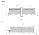
- the method may further include a step of heating the two ends of the molded body (hereinafter also referred to as step c). After step c, the two ends of the rope-shaped preform are brought into contact and placed in the mold to perform hot press molding, thereby strengthening the bonding between the ends and preventing the core from protruding. be able to.
- step c as shown in FIG. 5a), a heater 20 is sandwiched between the two ends of the rope-shaped preform 11, and the end faces are heated and melted, and then, as shown in FIG. 5b), The two ends can be brought into contact with each other.
- the method for manufacturing an annular sealing material of the present invention is shown in FIG. 6 in the heat press process or in the second heat press process described below in the case of performing feed press molding, from the viewpoint of preventing the core from protruding at the joint part.
- the method may further include the step of arranging the connecting member 40 between the two ends of the rope-shaped preform 11 to be placed in the mold and installing it in the mold (hereinafter also referred to as step d). can. Since the uncrosslinked outer layer 42 of the connecting member 40 is thicker than the uncrosslinked outer layer 12 of the rope-shaped preform 11, it is possible to easily prevent the core from protruding at the joint during hot pressing.
- the ratio of the thickness of the uncrosslinked outer layer 42 of the connecting member 40 to the thickness of the uncrosslinked outer layer 12 can be, for example, about 1.1 or more and 10 or less.
- the length of the connecting member 40 in the circumferential direction can be, for example, approximately 5 mm or more and 100 mm or less.
- the diameter of the cross section of the connecting member 40 is preferably the same, almost the same, or larger than the diameter of the cross section of the rope-shaped preform 11 from the viewpoint of reducing the step difference on the outer periphery of the annular sealing material.
- the connecting member 40 includes an uncrosslinked core 41 made of a crosslinkable rubber composition for a core, which will be described later, and an uncrosslinked outer layer 42, which covers the periphery of the uncrosslinked core 41 and is made of a crosslinkable rubber composition for an outer layer, which will be described later. can be included.
- the material constituting the uncrosslinked core 41 is preferably the same type of crosslinkable rubber composition for core as the crosslinkable rubber composition for core that constitutes the uncrosslinked core 13 of the rope-shaped preform 11.
- the material constituting the uncrosslinked outer layer 42 is preferably the same type of crosslinkable rubber composition for an outer layer as the crosslinkable rubber composition for an outer layer constituting the uncrosslinked outer layer 12 of the rope-shaped preform 11.
- the method for producing an annular sealing material may further include a secondary crosslinking step after the hot pressing step in order to promote crosslinking of uncrosslinked or insufficiently crosslinked portions.
- the heating temperature in the secondary crosslinking step may be, for example, approximately 150° C. or higher and 310° C. or lower.
- the feed press molding can include the following steps.
- a first hot press step in which the rope-shaped preform is placed in a first mold, and a portion of the rope-like preform other than the end portion is hot press-molded.
- a second hot press step in which two ends of the rope-shaped preform are placed in contact with each other in a second mold to perform hot press molding.
- the portions other than the ends of the rope-shaped preform can be brought into a crosslinked state.
- the first mold in which the rope-shaped preform is placed in the first hot press step may have a linear or arcuate cavity. After the rope-shaped preform is placed in the first mold, it can be pressed while being heated using a C-type press.
- the temperature of hot press molding in the first hot press step may be, for example, about 110° C. or higher and 220° C. or lower.
- the length of the portion to be cooled can be the length in the circumferential direction of the end portion of the rope-like preform to be in an uncrosslinked state or an insufficiently crosslinked state, and may be, for example, 1 mm or more and 600 mm or less.
- the two ends of the rope-like preform are placed in contact with each other in the second mold, and hot press molding is performed to join the ends of the rope-like preform in a crosslinked state.
- An annular sealing material can be obtained by repeatedly joining the ends of two or more rope-like preforms, or by joining the ends of one rope-like preform.
- the second mold in which the two ends of the rope-like preform are placed can have a linear arcuate cavity.
- the two ends of the rope-shaped preform placed in the second mold may each have a width in the circumferential direction of, for example, 50 mm or more and 600 mm or less.
- the two ends may be both ends of one rope-like preform, or one end of each of two rope-like preforms.
- the temperature of hot press molding in the second hot press step may be, for example, about 110° C. or higher and 220° C. or lower.
- the temperature of the hot press molding in the second hot press step is preferably lower than the temperature of the hot press molding in the first hot press step from the viewpoint of preventing cracking in the joint part and protrusion of the core. It is more preferable that the temperature is 5° C. or more and 20° C. or less lower than the hot press molding temperature in .
- the perfluoroelastomer is mixed with 1 part by mass of a crosslinking agent (Perhexa 25B) and 2 parts by mass of a crosslinking aid (TAIC) per 100 parts by mass of the perfluoroelastomer and kneaded using a kneader.
- a crosslinkable rubber composition was prepared.
- fluororubber 1 part by mass of a crosslinking agent (Perhexa 25B), 3 parts by mass of a crosslinking aid (TAIC), and 0.1 part by mass of a colorant (Crophtal Violet D5700) were added to 100 parts by mass of fluororubber.
- a crosslinkable rubber composition for core was prepared by blending and kneading using a kneader.
- the crosslinkable rubber composition for the outer layer and the crosslinkable rubber composition for the core are each formed into a sheet shape using a roller to a thickness of approximately 3 mm, and cut into a ribbon shape with a width of approximately 15 mm using a cutting machine. did.
- the cross-linkable rubber composition for the outer layer and the cross-linkable rubber composition for the core are put into a screw extruder equipped with a crosshead, and the outer layer is the cross-linkable rubber composition for the outer layer, and the core is the cross-linkable rubber composition for the core.
- the rope-shaped preform had a cross-sectional diameter of about 7.15 mm, an outer layer thickness of about 1.2 mm, and a length of 800 mm.
- each of the five rope-shaped preforms was placed in a first straight mold (length: 800 mm, cavity size: 7 mm), and both ends (width of one end: 100 mm) were left uncrosslinked. While both ends were cooled, parts other than both ends were hot press-molded using a C-type press at a temperature of 165°C.
- each of the two rope-shaped preforms after hot press molding was brought into contact, they were placed in a second mold for a joint, and the joint portion was hot press molded at a temperature of 160°C.
- the same operation was performed on the ends of the remaining rope-like preforms to join five rope-like preforms.
- secondary crosslinking was performed at a temperature of 200°C to obtain an annular sealing material.
- the obtained annular sealing material has a parting line on the outer circumferential side and an inner circumferential side, and the thickness of the outer layer in the part where the parting line exists is 200 ⁇ m, and the thickness of the outer layer in the part where the parting line does not exist.
- the thickness was 1200 ⁇ m, and the ratio of the thickness of the outer layer in the part where the parting line was not present to the thickness of the outer layer in the part where the parting line was present was 6/1.
- the obtained annular sealing material had an outer diameter of 1194 mm and an inner diameter of 1180 mm in plan view, and a cross-sectional diameter of 7 mm. Since the annular sealing material could be seen through the outer layer at the parting line, the parting line was easily visible and could be easily installed in the device without twisting or sagging.
Landscapes
- Engineering & Computer Science (AREA)
- General Engineering & Computer Science (AREA)
- Mechanical Engineering (AREA)
- Manufacturing & Machinery (AREA)
- Sealing Devices (AREA)
- Gasket Seals (AREA)
- Moulds For Moulding Plastics Or The Like (AREA)
- Compositions Of Macromolecular Compounds (AREA)
Abstract
本発明は、中芯と、前記中芯の周囲を覆う外層とを含む環状シール材であって、前記環状シール材は前記外層は外径側および内径側にパーティングラインを有し、前記環状シール材は、前記パーティングラインが存在する部分の少なくとも一部の外層の厚みが前記パーティングラインが存在しない部分の外層の厚みに比べ小さい環状シール材に関する。本発明によれば、視認性が向上したパーティングラインを有する環状シール材およびその製造方法が提供される。
Description
本発明は、環状シール材に関し、さらにはその製造方法にも関する。
各種用途に用いられるガスケットやパッキン等のシール材の製造方法として、材料を金型内に設置し、熱プレス成形により製造する方法が知られている(特開平08-151450号公報)。
熱プレス成形により製造した環状シール材は、金型の合わせ目に沿って表面上に形成された線状のパーティングラインを有する場合が多い。環状シール材の装置等への取り付けは、パーティングラインにねじれやたるみ等が生じていないか視認しながら行うことにより、正確かつ容易に行うことができる場合がある。
しかしながら、パーティングラインは、環状シール材を装置等に取り付けた際の密閉性の確保の観点からできる限り小さいことが望ましく、パーティングラインを視認することが困難である場合がある。
しかしながら、パーティングラインは、環状シール材を装置等に取り付けた際の密閉性の確保の観点からできる限り小さいことが望ましく、パーティングラインを視認することが困難である場合がある。
本発明の目的は、視認性が向上したパーティングラインを有する環状シール材およびその製造方法を提供することである。
本発明は、以下の環状シール材およびその製造方法を提供する。
[1] 中芯と、前記中芯の周囲を覆う外層とを含む環状シール材であって、前記環状シール材は外径側および内径側にパーティングラインを有し、前記環状シール材は、前記パーティングラインが存在する部分の少なくとも一部の外層の厚みが前記パーティングラインが存在しない部分の外層の厚みに比べ小さい、環状シール材。
[2] 前記外層の前記パーティングラインが存在する部分の厚みに対する前記パーティングラインが存在しない部分の厚みの比率は1.05~40である、請求項1に記載の環状シール材。
[3] 前記中芯は着色剤を含む、[1]または[2]に記載の環状シール材。
[4] 前記外層はパーフロロエラストマーおよびフッ素ゴムからなる群から選択される少なくとも1種の架橋物を含み、前記中芯は、パーフロロエラストマー、フッ素ゴム、シリコーンゴムおよびフロロシリコーンゴムからなる群から選択される少なくとも1種の架橋物を含む、[1]~[3]のいずれかに記載の環状シール材。
[5] [1]~[4]のいずれかに記載の環状シール材の製造方法であって、
中芯用架橋性ゴム組成物からなる未架橋中芯と、前記未架橋中芯の周囲を覆う外層用架橋性ゴム組成物からなる未架橋外層とを含むロープ状予備成形体を1または2以上準備する予備成形工程と、
前記ロープ状予備成形体の2つの端部を接触させて金型内に設置して熱プレス成形を行う熱プレス成形工程と
を含む、環状シール材の製造方法。
[6] 前記予備成形体を準備する工程は、前記中芯用架橋性ゴム組成物および前記外層用架橋性ゴム組成物を用いて押出成形する工程を含む、[5]に記載の環状シール材の製造方法。
本発明によれば、視認性が向上したパーティングラインを有する環状シール材およびその製造方法を提供することができる。
以下、図面を参照しつつ本発明の実施形態を説明するが、本発明は以下の実施形態に限定されるものではない。以下の全ての図面においては、各構成要素を理解し易くするために縮尺を適宜調整して示しており、図面に示される各構成要素の縮尺と実際の構成要素の縮尺とは必ずしも一致しない。
<環状シール材>
本発明の環状シール材は、中芯と中芯の周囲を覆う外層とを含み、外径側および内径側にパーティングラインを有し、パーティングラインが存在する部分の少なくとも一部の外層の厚みがパーティングラインが存在しない部分の外層の厚みに比べ小さいことを特徴とする。
本発明の環状シール材は、中芯と中芯の周囲を覆う外層とを含み、外径側および内径側にパーティングラインを有し、パーティングラインが存在する部分の少なくとも一部の外層の厚みがパーティングラインが存在しない部分の外層の厚みに比べ小さいことを特徴とする。
図1(a)は環状シール材の平面視における形状を示す。図1(a)において、環状シール材1は斜線部で示される。環状シール材1は、外周の直径である外径D1および内周の直径である内径D2を有する。外周および内周はそれぞれ、環状シール材1の平面視において外側および内側の円周である。平面視とは環状シール材1の厚み方向から見ることをいう。
図1(b)および(c)は、環状シール材1の平面に対して垂直な断面図を示す。環状シール材1は、中芯2と、中芯2の周囲を覆う外層3とを含む。図1(a)に示すように環状シール材1は断面形状が円形であることが好ましく、用途に応じて他の断面形状を有していてもよい。環状シール材1は、断面の径(直径)D3、外層3の厚みTを有する。
図1に示されていないが環状シール材1は、外径側および内径側にパーティングラインを有する。パーティングラインは、熱プレス成形工程において外層3の表面に生じる2つの金型の合わせ目の跡またはバリを除去した跡であることができる。環状シール材1は、外層3の表面上に外周および内周に沿って形成されたパーティングラインを有する。
図2に示すように、パーティングラインは、環状シール材1の断面において、外側に凸状になるように形成されていてよい。環状シール材1において、外層3は、パーティングラインが存在する部分の少なくとも一部の厚みT1がパーティングラインが存在しない部分の厚みT2に比べ小さい。外層3のパーティングラインが存在する部分の少なくとも一部の厚みT1がパーティングラインが存在しない部分の厚みT2に比べ小さいことにより、パーティングライン上において外層3を通して中芯2が視認され易くなるため、パーティングラインの視認性が向上し易くなる傾向にある。環状シール材1の外層3は、パーティングラインが存在する部分の一部において厚みT1を有していてもよく、パーティングラインが存在する部分の全部が厚みT1を有していてもよい。
外層3のパーティングラインが存在する部分の厚みT1に対するパーティングラインが存在しない部分の厚みT2の比率T2/T1は、1.05~40であり、中芯2が外層3を通して視認され易くなる観点から好ましくは1.2~20である。
中芯2(パーティングライン)をさらに視認し易くする観点から、中芯2は着色剤を含むことが好ましい。外層3は、着色剤を含んでいてもよく、含んでいなくてもよい。外層3が着色剤を含む場合、中芯2に含まれる着色剤とは異なる着色剤を含むことが好ましい。外層3は、中芯2(パーティングライン)の視認性の観点から着色剤を含まないことがより好ましい。
環状シール材1は、材料コスト低減の観点から好ましくは断面の径D3に対する外層3の厚みTの平均比率(以下、平均比率ともいう)が例えば1/35以上1/4以下であってよく、好ましくは1/20以上1/5以下である。平均比率は、環状シール材1においてランダムに選択した5箇所の断面において測定した比率の平均である。比率は、例えば環状シール材1の断面において最も大きい外層3の厚みTとその厚みを含む断面の径D3との比率T/D3で示される。
外層3の厚みTおよびパーティングラインが存在しない部分の厚みT2は、例え0.3mm以上10mm以下であってよく、好ましくは0.5mm以上3mm以下である。外層3のパーティングラインが存在する部分の厚みT1は、例えば0.1mm以上5mm以下であってよく、好ましくは0.2mm以上1.5mm以下である。
環状シール材1の断面の径D3は、例えば3mm以上50mm以下であってよく、好ましくは3mm以上15mm以下である。
環状シール材1の断面の径D3は、例えば3mm以上50mm以下であってよく、好ましくは3mm以上15mm以下である。
中芯2および外層3は、架橋性ゴム組成物の架橋物を含むことができる。以下、中芯2を形成する架橋性ゴム組成物は中芯用架橋性ゴム組成物、外層3を形成する架橋性ゴム組成物は外層用架橋性ゴム組成物、中芯用架橋性ゴム組成物および外層用架橋性ゴム組成物をいずれも指すときは架橋性ゴム組成物ともいう。
架橋性ゴム組成物は架橋性ゴム成分を含むことができる。架橋性ゴム成分は、架橋反応によって架橋構造を有するエラストマー(架橋ゴム)を形成することができる。架橋性ゴム成分は、炭素-炭素不飽和基、ニトリル基、ヒドロキシル基、アミノ基、カルボニル基、ハロゲン基等の架橋性部位を有することができる。
架橋性ゴム成分の具体例は、パーフルオロエラストマー(FFKM)、フッ素ゴム(FKM)、シリコーンゴム、フロロシリコーンゴム、エチレン-プロピレンゴム(EPM)、エチレン-プロピレン-ジエンゴム(EPDM)、ニトリルゴム(NBR;アクリロニトリルブタジエンゴム)、水素添加ニトリルゴム(HNBR;水素添加アクリロニトリルブタジエンゴム)、ブチルゴム(IIR)、アクリルゴムを含む。中でもパーフルオロエラストマー、フッ素ゴム、シリコーンゴムおよびフロロシリコーンゴムが好適に用いられる。架橋性ゴム組成物において架橋性ゴム成分は1種のみを用いてもよいし、2種以上を併用してもよい。
外層3はパーフロロエラストマーおよびフッ素ゴムからなる群から選択される少なくとも1種の架橋物を含み、中芯2は、パーフロロエラストマー、フッ素ゴム、シリコーンゴムおよびフロロシリコーンゴムからなる群から選択される少なくとも1種の架橋物を含むことが好ましい。したがって、外層用架橋性ゴム組成物における架橋性ゴム成分はパーフロロエラストマーおよびフッ素ゴムからなる群から選択される少なくとも1種であることが好ましく、より好ましくはパーフロロエラストマーである。中芯用架橋性ゴム組成物における架橋性ゴム成分は、パーフロロエラストマー、フッ素ゴム、シリコーンゴムおよびフロロシリコーンゴムからなる群から選択される少なくとも1種であることが好ましい。外層3は、耐ラジカル性の観点から有利にはパーフロロエラストマーの架橋物を含む。中芯2は、材料コストの観点から有利にはフッ素ゴム、シリコーンゴムおよびフロロシリコーンゴムからなる群から選択される少なくとも1種の架橋物を含む。
パーフルオロエラストマーとしては特に制限されず、例えば、テトラフルオロエチレン(TFE)-パーフルオロ(アルキルビニルエーテル)系共重合体や、TFE-パーフルオロ(アルコキシアルキルビニルエーテル)系共重合体等を挙げることができる。これらの共重合体は、他のパーフルオロモノマー由来の構成単位をさらに含んでいてもよい。パーフルオロエラストマーを含むパーフルオロエラストマー組成物によれば、水素原子含有フッ素エラストマーを含む架橋性ゴム組成物に比べて、耐オゾン性をより高めることができる。架橋性ゴム組成物は、パーフルオロエラストマーを1種のみ含んでいてもよいし、2種以上を含んでいてもよい。
テトラフルオロエチレン(TFE)-パーフルオロ(アルキルビニルエーテル)系共重合体を形成するパーフルオロ(アルキルビニルエーテル)は、アルキル基の炭素数が1~5であることができ、例えばパーフルオロ(メチルビニルエーテル)、パーフルオロ(エチルビニルエーテル)、パーフルオロ(プロピルビニルエーテル)等であることができる。好ましくは、パーフルオロ(メチルビニルエーテル)である。
TFE-パーフルオロ(アルコキシアルキルビニルエーテル)系共重合体を形成するパーフルオロ(アルコキシアルキルビニルエーテル)は、ビニルエーテル基(CF2=CFO-)に結合する基の炭素数が3~12であることができ、例えば
CF2=CFOCF2CF(CF3)OCnF2n+1、
CF2=CFO(CF2)3OCnF2n+1、
CF2=CFOCF2CF(CF3)O(CF2O)mCnF2n+1、または
CF2=CFO(CF2)2OCnF2n+1
であることができる。上記式中、nは例えば1~5であり、mは例えば1~3である。
CF2=CFOCF2CF(CF3)OCnF2n+1、
CF2=CFO(CF2)3OCnF2n+1、
CF2=CFOCF2CF(CF3)O(CF2O)mCnF2n+1、または
CF2=CFO(CF2)2OCnF2n+1
であることができる。上記式中、nは例えば1~5であり、mは例えば1~3である。
パーフルオロエラストマーは架橋性を有することが好ましく、より具体的には、架橋部位モノマーをさらに共重合させたもの(架橋部位モノマー由来の構成単位をさらに含むもの)であることが好ましい。架橋部位とは、架橋反応可能な部位を意味する。架橋部位としては、例えば、ニトリル基、ハロゲン基(例えば、I基、Br基等)、パーフルオロフェニル基等を挙げることができる。
架橋部位としてニトリル基を有する架橋部位モノマーの一例は、ニトリル基含有パーフルオロビニルエーテルである。ニトリル基含有パーフルオロビニルエーテルとしては、例えば、
CF2=CFO(CF2)nOCF(CF3)CN(nは例えば2~4)、
CF2=CFO(CF2)nCN(nは例えば2~12)、
CF2=CFO[CF2CF(CF3)O]m(CF2)nCN(nは例えば2、mは例えば1~5)、
CF2=CFO[CF2CF(CF3)O]m(CF2)nCN(nは例えば1~4、mは例えば1~2)、
CF2=CFO[CF2CF(CF3)O]nCF2CF(CF3)CN(nは例えば0~4)
等を挙げることができる。
CF2=CFO(CF2)nOCF(CF3)CN(nは例えば2~4)、
CF2=CFO(CF2)nCN(nは例えば2~12)、
CF2=CFO[CF2CF(CF3)O]m(CF2)nCN(nは例えば2、mは例えば1~5)、
CF2=CFO[CF2CF(CF3)O]m(CF2)nCN(nは例えば1~4、mは例えば1~2)、
CF2=CFO[CF2CF(CF3)O]nCF2CF(CF3)CN(nは例えば0~4)
等を挙げることができる。
架橋部位としてハロゲン基を有する架橋部位モノマーの一例は、ハロゲン基含有パーフルオロビニルエーテルである。ハロゲン基含有パーフルオロビニルエーテルとしては、例えば、上述のニトリル基含有パーフルオロビニルエーテルの具体例において、ニトリル基をハロゲン基に置き換えたものを挙げることができる。
架橋性のパーフルオロエラストマーは、2つの主鎖間を架橋する架橋構造を有していてもよい。
パーフルオロエラストマーにおけるTFE由来の構成単位/パーフルオロ(アルキルビニルエーテル)又はパーフルオロ(アルコキシアルキルビニルエーテル)由来の構成単位/架橋部位モノマー由来の構成単位の比は、モル比で、通常50~79.6%/20~49.8%/0.2~5%であり、好ましくは60~74.8%/25~39.5%/0.5~2%である。架橋性ゴム組成物は、上記構成単位の比が異なる2種以上のパーフルオロエラストマーを含むこともできる。
フッ素ゴムは、フッ化ビニリデン/ヘキサフルオロプロピレン共重合体等の2元系のフッ化ビニリデン系ゴム、フッ化ビニリデン/テトラフルオロエチレン/ヘキサフルオロプロピレン共重合体、フッ化ビニリデン/テトラフルオロエチレン/パーフルオロアルキルビニルエーテル共重合体、フッ化ビニリデン/テトラフルオロエチレン/プロピレン共重合体等の3元系のフッ化ビニリデン系ゴム、テトラフルオロエチレン/プロピレン共重合体、エチレン/テトラフルオロエチレン/パーフルオロメチルビニルエーテル共重合体、熱可塑性フッ素ゴム、パーフルオロポリエーテル骨格の液状フッ素ゴム(例えば信越化学工業株式会社製「SIFEL(登録商標)」等)を挙げることができる。フッ素ゴムは、1種のみを単独で用いてもよいし、2種以上を併用してもよい。
フッ素ゴムは、官能基を含有するものであってもよい。官能基は、例えば当該官能基を有する架橋部位モノマーを共重合させることによって導入できる。架橋部位モノマーは、ハロゲン基含有モノマーであることができる。
架橋性ゴム組成物は、架橋性ゴム成分の架橋系に応じた架橋剤を任意に共架橋剤(架橋助剤)と共に含むことができる。パーフルオロエラストマーの架橋系としては、例えばパーオキサイド架橋系、トリアジン架橋系、オキサゾール架橋系、イミダゾール架橋系、チアゾール架橋系、ビスフェノール架橋系等が挙げられる。フッ化ビニリデン系ゴムおよびテトラフルオロエチレン-プロピレンゴムの架橋系としては、例えばパーオキサイド架橋系、ポリアミン架橋系、ポリオール架橋系等が挙げられる。架橋性ゴム組成物は、いずれか1種の架橋系で架橋されてもよいし、2種以上の架橋系で架橋されてもよい。
パーオキサイド架橋剤は、例えば2,5-ジメチル-2,5-ジ(t-ブチルペルオキシ)ヘキサン(市販品の例:日油株式会社製「パーヘキサ25B」、「パーヘキサ25B-40」);ジクミルペルオキシド(市販品の例:日油株式会社製「パークミルD」);2,4-ジクロロベンゾイルパーオキサイド;ジ-t-ブチルパーオキサイド;t-ブチルジクミルパーオキサイド;ベンゾイルペルオキシド(市販品の例:日油株式会社製「ナイパーB」);2,5-ジメチル-2,5-(t-ブチルペルオキシ)ヘキシン-3(市販品の例:日油株式会社製「パーヘキシン25B」);2,5-ジメチル-2,5-ジ(ベンゾイルパーオキシ)ヘキサン;α,α’-ビス(t-ブチルペルオキシ-m-イソプロピル)ベンゼン(市販品の例:日油株式会社製「パーブチルP」);t-ブチルパーオキシイソプロピルカーボネート;パラクロロベンゾイルパーオキサイド等であることができる。パーオキサイド架橋剤は、1種のみを用いてもよいし、2種以上を併用してもよい。
パーオキサイド架橋系で用いる共架橋剤としては、トリアリルイソシアヌレート(市販品の例:三菱ケミカル株式会社製「TAIC」);トリアリルシアヌレート;トリアリルホルマール;トリアリルトリメリテート;N,N’-m-フェニレンビスマレイミド;ジプロパギルテレフタレート;ジアリルフタレート;テトラアリルテレフタルアミド等のラジカルによる共架橋が可能な化合物(不飽和多官能性化合物)を挙げることができる。共架橋剤は、1種のみを用いてもよいし、2種以上を併用してもよい。上記の中でも、反応性及び耐熱性(圧縮永久歪特性)の観点から、共架橋剤はトリアリルイソシアヌレートを含むことが好ましい。
トリアジン架橋系においては、有機スズ化合物、4級ホスホニウム塩や4級アンモニウム塩等のオニウム塩、尿素、窒化ケイ素等の架橋触媒が用いられる。
オキサゾル架橋系で用いる架橋剤としては、例えば、2,2-ビス(3-アミノ-4-ヒドロキシフェニル)ヘキサフルオロプロパン(BOAP)、4,4’-スルホニルビス(2-アミノフェノール)、9,9-ビス(3-アミノ-4-ヒドロキシフェニル)フルオレンを含む。好ましくは、BOAPが用いられる。
イミダゾル架橋系、チアゾール架橋系で用いる架橋剤としては、従来公知のものを用いることができる。イミダゾル架橋系で用いる架橋剤としては、3,3’,4,4’-テトラアミノベンゾフェノン、3,3’-ジアミノベンジジン等を挙げることができる。
架橋性ゴム組成物における架橋剤(2種以上を用いる場合はその合計量)の含有量は、架橋性ゴム成分の総量100質量部に対して、例えば0.1~10質量部であり、好ましくは0.2~5質量部であり、より好ましくは0.3~3質量部である。
架橋性ゴム組成物における共架橋剤(2種以上を用いる場合はその合計量)の含有量は、架橋性ゴム成分の総量100質量部に対して、例えば0.5~10質量部であり、耐熱性向上の観点から、好ましくは1~8質量部である。
架橋性ゴム組成物は、加工性改善や物性調整等を目的として、必要に応じて、老化防止剤、酸化防止剤、加硫促進剤、加工助剤(ステアリン酸等)、安定剤、粘着付与剤、シランカップリング剤、可塑剤、難燃剤、離型剤、ワックス類、滑剤等の添加剤を含むことができる。添加剤の他の例は、フッ素系オイル(例えば、パーフルオロエーテル等)のような粘着性低減(防止)剤である。添加剤は1種のみを用いてもよいし、2種以上を併用してもよい。
ただし、環状シール材を高温環境下で使用する場合等においては、揮発、溶出又は析出を生じるおそれがあることから、添加剤の量はできるだけ少ないことが好ましく(例えば架橋性ゴム成分の総量100質量部に対して10質量部以下、好ましくは5質量部以下、より好ましくは2質量部以下、さらに好ましくは1質量部以下)、添加剤を含有しないことが望ましい。
また、架橋性ゴム組成物は、必要に応じて着色剤およびフィラーからなる群から選択される少なくとも1種を含むことができる。着色剤およびフィラーはそれぞれ、1種のみを用いてもよいし、2種以上を併用してもよい。
着色剤としては、例えば無機顔料および有機顔料からなる群から選択される少なくとも1種が挙げられる。無機顔料としては、例えば白色顔料(例えばシリカ、亜鉛華、鉛白、リトポン、二酸化チタン、沈降性硫酸バリウムおよびバライト粉等)、赤色顔料(例えば鉛丹、酸化鉄赤等)、黄色顔料(例えば黄鉛、亜鉛黄等)、青色顔料(例えばウルトラマリン青、プロシア青、YInMnブルー等)、黒色顔料(例えばカーボンブラック等)等が挙げられる。有機顔料としては、例えばアゾ顔料(アゾレーキ顔料、不溶性アゾ顔料、縮合アゾ顔料等);アントラキノン系顔料、チオインジゴ系顔料、ペリノン系顔料、ペリレン系顔料、キナクリドン系顔料、イソインドリノン顔料、イソインドリン顔料、ジオキサジン顔料、キノフタロン顔料、ジケトピロロピロール顔料等の多環式顔料、フタロシアニン系顔料等が挙げられる。有機顔料としてカラーインデックスにおいてピグメントに分類されている有機顔料を使用することができる。好ましく用いられる顔料は、金属元素を含有しない有機顔料である。金属元素を含有しない有機顔料は、シール材が半導体用途など過酷なオゾン環境下で用いられ、環状シール材がエッチングされることがあっても、金属元素由来の物質が飛散させるおそれがない。
架橋性ゴム組成物中の着色剤の含有量(2種以上を用いる場合はその合計量)は、例えば架橋性ゴム成分100質量部に対し、0.01質量部以上2質量部未満であってよく、好ましくは0.05質量部以上1.5質量部以下であり、より好ましくは0.1質量部以上1質量部以下である。
フィラーとしては、例えばフッ素樹脂、シリカ、アルミナ、酸化亜鉛、酸化チタン、クレー、タルク、珪藻土、硫酸バリウム、炭酸カルシウム、炭酸マグネシウム、酸化カルシウム、マイカ、グラファイト、水酸化アルミニウム、ケイ酸アルミニウム、ハイドロタルサイト、金属粉、ガラス粉、セラミックス粉等を用いることができる。フィラーは、1種のみを用いてもよいし、2種以上を併用してもよい。架橋性ゴム組成物におけるフィラーの含有量(2種以上を用いる場合はその合計量)は、架橋性ゴム成分の総量100質量部に対して、例えば0.1質量部以上40質量部以下であり、機械的強度向上の観点から、好ましくは1質量部以上30質量部以下であり、より好ましくは1質量部より多く30質量部以下である。本明細書においてフィラーは上述の着色剤としての有機顔料および無機顔料とは区別され、有機顔料および無機顔料とは異なった種類のものを用いることができる。
架橋性ゴム組成物がフッ素樹脂のフィラーを含む場合、架橋物の耐オゾン性や機械的強度をさらに向上させ得る。フッ素樹脂は、例えばフッ素樹脂粒子として架橋性ゴム組成物に含有させることができる。
フィラーとして用いるフッ素樹脂は、分子内にフッ素原子を有する樹脂であり、例えば、ポリテトラフルオロエチレン(PTFE)、テトラフルオロエチレン-パーフルオロアルキルビニルエーテル共重合体(PFA)、テトラフルオロエチレン-ヘキサフルオロプロピレン共重合体(FEP)、テトラフルオロエチレン-エチレン共重合体(ETFE)、ポリクロロトリフルオロエチレン(PCTFE)、クロロトリフルオロエチレン-エチレン共重合体(ECTFE)、ポリフッ化ビニリデン(PVDF)、ポリビニルフルオライド(PVF)、フッ化ビニリデン-ヘキサフルオロプロピレン共重合体(VDF-HFP共重合体)、フッ化ビニリデン-ヘキサフルオロプロピレン-テトラフルオロエチレン共重合体(VDF-HFP-TFE共重合体)等であることができる。フッ素樹脂は1種のみを単独で用いてもよいし、2種以上を併用してもよい。
上記の中でも、高温環境下で樹脂が溶融して圧縮永久歪等の特性が損なわれることを防ぐ観点から、PFA、PTFE等の融点が比較的高いフッ素樹脂を用いることが好ましい。
フィラーとして用いるフッ素樹脂は官能基を含有するものであってもよい。官能基は、例えば当該官能基を有するモノマーを共重合させることによって導入できる。官能基を有するモノマーとして上述の架橋部位モノマーを共重合させると、上記架橋剤によってフッ素樹脂とパーフルオロエラストマーとの架橋も進行するので、パーフルオロエラストマー組成物の架橋物の機械的強度等をさらに高め得る。官能基を含有するフッ素樹脂の例として、特開2013-177631号公報に記載されるニトリル基含有ポリテトラフルオロエチレンを挙げることができる。また、フッ素樹脂は、例えば「TFM変性PTFE」(ダイニオン社製)のような、変性されたフッ素樹脂であることもできる。
架橋性ゴム組成物がパーフルオロエラストマーとフッ素樹脂のフィラーとを含む場合、例えば1)パーフルオロエラストマー粉末とフッ素樹脂粉末とをミキシングロールを用いて混練する方法、2)パーフルオロエラストマー粉末又はペレットとフッ素樹脂粉末又はペレットとをミキサーや二軸押出機等の装置を用いて溶融混練する方法のほか、3)パーフルオロエラストマーの調製段階でフッ素樹脂を添加する方法により製造したフッ素樹脂入りパーフルオロエラストマーを用いることができる。
上記3)の方法としては、いずれも乳化重合法で得られたパーフルオロエラストマーの水性分散液とフッ素樹脂の水性分散液とを混合した後、共凝析によりパーフルオロエラストマーとフッ素樹脂との混合物を得る方法を挙げることができる。
架橋性ゴム組成物は、架橋性ゴム成分、着色剤、架橋剤、必要に応じて添加される共架橋剤、フィラー及び添加剤を均一に混練りすることにより調製できる。混練り機としては、例えばミキシングロール、加圧ニーダー、インターナルミキサー(バンバリーミキサー)等の従来公知のものを用いることができる。各配合成分は一度に混合して混練してもよいし、各配合成分のうち、架橋反応に寄与する成分(架橋促進剤、架橋遅延剤、架橋剤等)を除く成分を先に均一に混練しておき、その後、架橋反応に寄与する成分を混練する等、複数段に分けて混練してもよい。
環状シール材1の製造方法は、例えば以下の工程を含むことができる。
中芯用架橋性ゴム組成物からなる未架橋中芯と、未架橋中芯の周囲を覆う外層用架橋性ゴム組成物からなる未架橋外層とを含むロープ状予備成形体を1または2以上準備する予備成形工程。
ロープ状予備成形体の2つの端部を接触させて金型内に設置し、熱プレス成形を行う熱プレス工程。
中芯用架橋性ゴム組成物および外層用架橋性ゴム組成物については、上述の環状シール材における説明が適用される。
中芯用架橋性ゴム組成物からなる未架橋中芯と、未架橋中芯の周囲を覆う外層用架橋性ゴム組成物からなる未架橋外層とを含むロープ状予備成形体を1または2以上準備する予備成形工程。
ロープ状予備成形体の2つの端部を接触させて金型内に設置し、熱プレス成形を行う熱プレス工程。
中芯用架橋性ゴム組成物および外層用架橋性ゴム組成物については、上述の環状シール材における説明が適用される。
(予備成形工程)
予備成形工程は、中芯用架橋性ゴム組成物および外層用架橋性ゴム組成物を用いて押出成形する工程を含むことができる。ロープ状予備成形体は、例えば次のように作製することができる。まず、中芯用架橋性ゴム組成物と外層用架橋性ゴム組成物とをロールを用いてシート状に成形し、シート状成形物を作製する。シート状成形物の厚みは、例えば1mm以上5mm以下であってよい。次にシート状成形物を裁断機で、例えば幅5mm以上30mm以下のリボン状成形物に裁断する。その後、クロスヘッドがついたスクリュー式押出機に中芯用架橋性ゴム組成物と外層用架橋性ゴム組成物のリボン状成形物を投入してロープ状に押し出すことにより、外層が外層用架橋性ゴム組成物、中芯が中芯用架橋性ゴム組成物から構成される2層構造を有するロープ状予備成形体を得ることができる。ロープ状に押し出す速度は、例えば100mm/分以上1000mm/分以下であることができる。
予備成形工程は、中芯用架橋性ゴム組成物および外層用架橋性ゴム組成物を用いて押出成形する工程を含むことができる。ロープ状予備成形体は、例えば次のように作製することができる。まず、中芯用架橋性ゴム組成物と外層用架橋性ゴム組成物とをロールを用いてシート状に成形し、シート状成形物を作製する。シート状成形物の厚みは、例えば1mm以上5mm以下であってよい。次にシート状成形物を裁断機で、例えば幅5mm以上30mm以下のリボン状成形物に裁断する。その後、クロスヘッドがついたスクリュー式押出機に中芯用架橋性ゴム組成物と外層用架橋性ゴム組成物のリボン状成形物を投入してロープ状に押し出すことにより、外層が外層用架橋性ゴム組成物、中芯が中芯用架橋性ゴム組成物から構成される2層構造を有するロープ状予備成形体を得ることができる。ロープ状に押し出す速度は、例えば100mm/分以上1000mm/分以下であることができる。
ロープ状予備成形体の断面の径は例えば3mm以上50mm以下であってよく、好ましくは3mm以上15mm以下である。ロープ状予備成形体における外層厚みは例えば0.1mm以上10mm以下であってよく、好ましくは0.2mm以上3mm以下である。ロープ状予備成形体の長さは例えば100mm以上5000mm以下であってよい。
リボン状成形物は、上述のシート状成形物を作製することなく、中芯用架橋性ゴム組成物および外層用架橋性ゴム組成物をプランジャー式押出機に投入し、リボン状に押出することにより作製することもできる。
準備するロープ状予備成形体の本数は、1本であってよく、2本以上、例えば3~10本であってよく、環状シール材の内径および/または外径に応じて調節することができる。
(熱プレス工程)
熱プレス工程において、未架橋中芯および未架橋外層を加熱しながらプレス成形することにより、架橋性ゴム組成物の架橋物を含む中芯2および外層3からなる環状シール材1を得ることができる。熱プレス成形における加熱温度は、例えば110℃以上220℃以下程度であってよい。
熱プレス工程において、未架橋中芯および未架橋外層を加熱しながらプレス成形することにより、架橋性ゴム組成物の架橋物を含む中芯2および外層3からなる環状シール材1を得ることができる。熱プレス成形における加熱温度は、例えば110℃以上220℃以下程度であってよい。
環状シール材1において、外層3のパーティングラインが存在する部分の少なくとも一部の厚みT1をパーティングラインが存在しない部分の厚みT2に比べ小さくする手段としては、例えば、クロスヘッドの口金形状を調整し、ロープ断面における0°と180°の位置の外層の肉厚が小さくなるロープ状予備成形体を作成し、0°と180°の位置をパーティングラインとなるように金型にロープ状予備成形体を設置する方法がある。別の手段としては、パーティングラインからのバリが多くなるように材料の投入量を調整する方法がある。
熱プレス工程において、環状のキャビティを有する金型を用いてロープ状予備成形体の2つの端部を接触させて熱プレスを行うことにより環状シール材を作製してよく、または直線状や円弧状のキャビティを有する金型を用いて、まずロープ状予備成形体の端部以外を熱プレス成形して直線状や円弧状の成形体を得た後、この直線状や円弧状の成形体の2つの端部を接触させた接合部を熱プレス成形することにより環状シール材を作製する送りプレス成形を行ってもよい。2つの端部を接触させる態様にはロープ状予備成形体の2つの端面が接触した状態が含まれる。接合部の周長方向における長さは例えば100mm以上1200mm以下であってよい。送りプレス成形について後に説明する。
熱プレス工程は、ロープ状予備成形体の端部を繋いだ接合部において外層のワレや外層からの中芯のはみ出しを防止する観点から、環状のキャビティを有する金型内に設置する前に、または送りプレス成形を行う場合、後述の第2熱プレス工程前に(直線状や円弧状のキャビティを有する金型に設置する前に)、図3に示すように、接触させたロープ状予備成形体11の2つの端部の合わせ目の周囲に未架橋薄膜層30を巻付ける工程(以下、工程aともいう)をさらに含むことができる。
未架橋薄膜層30の厚みは、例えば0.05mm以上5mm以下であってよく、ロープ状予備成形体11の外周の段差低減の観点から好ましくは0.1mm以上1mm以下である。
未架橋薄膜層30を構成する材料は、上述の外層用架橋性ゴム組成物であってよく、好ましくはロープ状予備成形体11の外層12を構成する外層用架橋性ゴム組成物と同一の種類の外層用架橋性ゴム組成物である。
未架橋薄膜層30は、外層用架橋性ゴム組成物をロールを用いてシート状に成形し、裁断機で、例えば幅5mm以上100mm以下程度のリボン状成形物に裁断し、これをロープ状予備成形体11の合わせ目に巻付ける長さに応じてさらに裁断することにより得られる。また、ロープ状予備成形体から中芯材料を取り除いたものを未架橋薄膜層30として用いることもできる。
工程aにおいて、未架橋薄膜層30は、ロープ状予備成形体11の合わせ目に1周巻付けてよく、2周以上巻付けてもよい。ロープ状予備成形体11の外周の段差低減の観点から、未架橋薄膜層30はロープ状予備成形体11の合わせ目に1周から2周巻付けることが好ましい。
本発明の環状シール材の製造方法は、接合部において中芯のはみ出しを防止する観点から、熱プレス工程前または後述の第2熱プレス工程前に、図4a)に示すように、ロープ状予備成形体11の2つの端部から未架橋中芯14を取り除く工程(以下、工程bともいう)をさらに含むことができる。図4b)に示すように、未架橋中芯を取り除いた2つの端部(外層12)を接触させて金型内に設置して熱プレス成形を行うことにより、接合部において中芯のはみ出しを防止し易くすることができる。
工程bは、熱プレス工程前に行ってよく、送りプレス成形を行う場合、後述の第1熱プレス工程前に行ってもよいし、第1熱プレス工程と第2熱プレス工程との間に行ってもよい。
取り除く未架橋中芯14は、端面から内側に例えば0.1mm以上20mm以下の範囲であることができる。未架橋中芯14は、例えばハサミ、メス、ニッパ等を用いて取り除くことができる。
本発明の環状シール材の製造方法は、端部同士の接合性を向上させる観点から、熱プレス工程前に、または送りプレス成形を行う場合、後述の第2熱プレス工程前に、ロープ状予備成形体の2つの端部を加熱する工程(以下、工程cともいう)をさらに含むことができる。工程c後に、ロープ状予備成形体の2つの端部を接触させて金型内に設置して熱プレス成形を行うことにより、端部同士の接合性を強化し、中芯のはみ出しを防止することができる。
工程cにおいて、図5a)に示すように、ロープ状予備成形体11の2つの端部の間にヒーター20を挟み、端面を加熱して溶融させ、その後、図5b)に示すように、溶融した端部同士を接触することができる。
本発明の環状シール材の製造方法は、接合部において中芯のはみ出しを防止する観点から、熱プレス工程において、または送りプレス成形を行う場合、後述の第2熱プレス工程において、図6に示すように、金型内に設置するロープ状予備成形体11の2つの端部の間に接続部材40を配置して金型内に設置する工程(以下、工程dともいう)をさらに含むことができる。接続部材40の未架橋外層42は、ロープ状予備成形体11の未架橋外層12より厚みが大きいため、熱プレスの際に接合部において中芯のはみ出しを防止し易くすることができる。
未架橋外層12の厚みに対する接続部材40の未架橋外層42の厚みの比率は、例えば1.1以上10以下程度であることができる。接続部材40の周長方向における長さは例えば5mm以上100mm以下程度であることができる。
接続部材40の断面の径は、環状シール材の外周の段差低減の観点から、ロープ状予備成形体11の断面の径と同一またはほぼ同一であること、または大きいことが好ましい。
接続部材40は、後述する中芯用架橋性ゴム組成物からなる未架橋中芯41と、未架橋中芯41の周囲を覆う後述する外層用架橋性ゴム組成物からなる未架橋外層42とを含むことができる。未架橋中芯41を構成する材料は、好ましくはロープ状予備成形体11の未架橋中芯13を構成する中芯用架橋性ゴム組成物と同一の種類の中芯用架橋性ゴム組成物である。未架橋外層42を構成する材料は、好ましくはロープ状予備成形体11の未架橋外層12を構成する外層用架橋性ゴム組成物と同一の種類の外層用架橋性ゴム組成物である。
環状シール材の製造方法は、熱プレス工程の後に、未架橋または架橋が不十分な部分の架橋を促進させるために二次架橋工程をさらに含むことができる。二次架橋工程において加熱する温度は、例えば150℃以上310℃以下程度であってよい。
(送りプレス成形)
熱プレス工程において送りプレス成形を行う場合、送りプレス成形は、以下の工程を含むことができる。
ロープ状予備成形体を第1金型内に設置し、ロープ状予備成形体の端部以外の部分を熱プレス成形する第1熱プレス工程。
ロープ状予備成形体の2つの端部を接触させて第2金型内に設置し、熱プレス成形を行う第2熱プレス工程。
熱プレス工程において送りプレス成形を行う場合、送りプレス成形は、以下の工程を含むことができる。
ロープ状予備成形体を第1金型内に設置し、ロープ状予備成形体の端部以外の部分を熱プレス成形する第1熱プレス工程。
ロープ状予備成形体の2つの端部を接触させて第2金型内に設置し、熱プレス成形を行う第2熱プレス工程。
第1熱プレス工程では、ロープ状予備成形体の端部以外の部分を架橋状態とすることができる。第1熱プレス工程においてロープ状予備成形体を設置する第1金型は、直線状や円弧状のキャビティを有することができる。ロープ状予備成形体は、第1金型内に設置した後、C型プレスにより加熱しながらプレスすることができる。第1熱プレス工程における熱プレス成形の温度は、例えば110℃以上220℃以下程度であってよい。
ロープ状予備成形体の端部以外の部分を熱プレス成形する方法としては、例えば第1金型のロープ状予備成形体の端部に相当する部位を冷却装置等を用いて冷却する方法等が挙げられる。冷却する部位の長さは、ロープ状予備成形体の未架橋状態または架橋が不十分な状態とする端部の周長方向における長さとすることができ、例えば1mm以上600mm以下であってよい。
第2熱プレス工程において、ロープ状予備成形体の2つの端部を接触させて第2金型内に設置し、熱プレス成型を行うことでロープ状予備成形体の端部を架橋状態として接合することができる。2本以上のロープ状予備成形体の端部同士の接合を繰返し行うことにより、あるいは1本のロープ状予備成形体の端部同士を接合することにより環状シール材を得ることができる。
ロープ状予備成形体の2つの端部を設置する第2金型は、直線状の円弧状のキャビティを有することができる。第2金型内に設置するロープ状予備成形体の2つの端部はそれぞれ周長方向における幅が、例えば50mm以上600mm以下であってよい。2つの端部は、1本のロープ状予備成形体の両端部であってよく、2本のロープ状予備成形体のそれぞれの一方の端部であってよい。
第2熱プレス工程における熱プレス成形の温度は、例えば110℃以上220℃以下程度であってよい。第2熱プレス工程における熱プレス成形の温度は、接合部におけるワレや中芯のはみ出しの防止の観点から、第1熱プレス工程における熱プレス成形の温度より低いことが好ましく、第1熱プレス工程における熱プレス成形の温度より5℃以上20℃以下低いことがより好ましい。
以下、実施例により本発明をさらに詳細に説明する。例中の「%」及び「部」は、特記のない限り、質量%及び質量部である。
<実施例1>
パーフロロエラストマーと、パーフロロエラストマー100質量部に対し1質量部の架橋剤(パーヘキサ25B)と2質量部の架橋助剤(TAIC)とを配合してニーダーを用いて混練りすることにより外層用架橋性ゴム組成物を作製した。次にフッ素ゴムと、フッ素ゴム100質量部に対し1質量部の架橋剤(パーヘキサ25B)と3質量部の架橋助剤(TAIC)と、0.1質量部の着色剤(Cromphtal Violet D5700)を配合してニーダーを用いて混練りすることにより中芯用架橋性ゴム組成物を作製した。次に外層用架橋性ゴム組成物および中芯用架橋性ゴム組成物をそれぞれ厚みが約3mmとなるようにローラーを用いてシート状に成形し、裁断機で幅が約15mmのリボン状に裁断した。クロスヘッドが備わったスクリュー式押出機にリボン状に成形した外層用架橋性ゴム組成物と中芯用架橋性ゴム組成物を投入し、外層が外層用架橋性ゴム組成物、中芯が中芯用架橋性ゴム組成物からなる2層構造を有するロープ状の予備成形体を5本作製した。ロープ状の予備成形体の断面の径は約7.15mm、外層厚みは約1.2mm、長さは800mmであった。
パーフロロエラストマーと、パーフロロエラストマー100質量部に対し1質量部の架橋剤(パーヘキサ25B)と2質量部の架橋助剤(TAIC)とを配合してニーダーを用いて混練りすることにより外層用架橋性ゴム組成物を作製した。次にフッ素ゴムと、フッ素ゴム100質量部に対し1質量部の架橋剤(パーヘキサ25B)と3質量部の架橋助剤(TAIC)と、0.1質量部の着色剤(Cromphtal Violet D5700)を配合してニーダーを用いて混練りすることにより中芯用架橋性ゴム組成物を作製した。次に外層用架橋性ゴム組成物および中芯用架橋性ゴム組成物をそれぞれ厚みが約3mmとなるようにローラーを用いてシート状に成形し、裁断機で幅が約15mmのリボン状に裁断した。クロスヘッドが備わったスクリュー式押出機にリボン状に成形した外層用架橋性ゴム組成物と中芯用架橋性ゴム組成物を投入し、外層が外層用架橋性ゴム組成物、中芯が中芯用架橋性ゴム組成物からなる2層構造を有するロープ状の予備成形体を5本作製した。ロープ状の予備成形体の断面の径は約7.15mm、外層厚みは約1.2mm、長さは800mmであった。
次いで、5本のロープ状予備成形体について、それぞれストレート型(長さ800mm、キャビティ寸法7mm)の第1金型に設置し、両端部(片方の端部の幅100mm)が未架橋状態となるように両端部を冷却しながら、両端部以外を温度165℃でC型プレスにより熱プレス成形した。
熱プレス成形後の2本のロープ状予備成形体のそれぞれの一方の端部を接触させた後、ジョイント用の第2金型に設置し、温度160℃で接合部を熱プレス成形した。残りのロープ状予備成形体の端部についても同様の操作を行い、5本のロープ状予備成形体を接合した。その後、温度200℃で二次架橋を行い環状シール材を得た。
得られた環状シール材は、外周側および内周側にパーティングラインを有し、パーティングラインが存在する部分の外層の厚みは200μmであり、パーティングラインが存在しない部分の外層の厚みは1200μmであり、パーティングラインが存在する部分の外層の厚みに対するパーティングラインが存在しない部分の外層の厚みの比率は6/1であった。また、得られた環状シール材は、平面視における外径が1194mm、内径が1180mmであり、断面における断面の径が7mmであった。環状シール材は、パーティングラインにおいて外層を通して中芯を視認できることからパーティングラインが視認し易く、ねじれやたるみを生じさせることなく容易に装置に設置することができた。
1 環状シール材、2 中芯、3 外層、11 ロープ状予備成形体、12 未架橋外層、13 未架橋中芯、14 取り除く未架橋中芯、20 ヒーター、30 未架橋薄膜層、40 接続部材、41 未架橋中芯、42 未架橋外層、T 外層の厚み、T1 外層のパーティングラインが存在する部分の厚み、T2 外層のパーティングラインが存在しない部分の厚み、D1 外径、D2 内径、D3 断面の径。
Claims (6)
- 中芯と、前記中芯の周囲を覆う外層とを含む環状シール材であって、前記環状シール材は外径側および内径側にパーティングラインを有し、前記環状シール材は、前記パーティングラインが存在する部分の少なくとも一部の外層の厚みが前記パーティングラインが存在しない部分の外層の厚みに比べ小さい、環状シール材。
- 前記外層の前記パーティングラインが存在する部分の厚みに対する前記パーティングラインが存在しない部分の厚みの比率は1.05~40である、請求項1に記載の環状シール材。
- 前記中芯は着色剤を含む、請求項1または2に記載の環状シール材。
- 前記外層はパーフロロエラストマーおよびフッ素ゴムからなる群から選択される少なくとも1種の架橋物を含み、前記中芯は、パーフロロエラストマー、フッ素ゴム、シリコーンゴムおよびフロロシリコーンゴムからなる群から選択される少なくとも1種の架橋物を含む、請求項1~3のいずれか1項に記載の環状シール材。
- 請求項1~4のいずれか一項に記載の環状シール材の製造方法であって、
中芯用架橋性ゴム組成物からなる未架橋中芯と、前記未架橋中芯の周囲を覆う外層用架橋性ゴム組成物からなる未架橋外層とを含むロープ状予備成形体を1または2以上準備する予備成形工程と、
前記ロープ状予備成形体の2つの端部を接触させて金型内に設置して熱プレス成形を行う熱プレス成形工程と
を含む、環状シール材の製造方法。 - 前記予備成形体を準備する工程は、前記中芯用架橋性ゴム組成物および前記外層用架橋性ゴム組成物を用いて押出成形する工程を含む、請求項5に記載の環状シール材の製造方法。
Applications Claiming Priority (2)
| Application Number | Priority Date | Filing Date | Title |
|---|---|---|---|
| JP2022-056238 | 2022-03-30 | ||
| JP2022056238A JP2023148300A (ja) | 2022-03-30 | 2022-03-30 | 環状シール材および製造方法 |
Publications (1)
| Publication Number | Publication Date |
|---|---|
| WO2023189732A1 true WO2023189732A1 (ja) | 2023-10-05 |
Family
ID=88201074
Family Applications (1)
| Application Number | Title | Priority Date | Filing Date |
|---|---|---|---|
| PCT/JP2023/010605 WO2023189732A1 (ja) | 2022-03-30 | 2023-03-17 | 環状シール材および製造方法 |
Country Status (3)
| Country | Link |
|---|---|
| JP (1) | JP2023148300A (ja) |
| TW (1) | TW202402517A (ja) |
| WO (1) | WO2023189732A1 (ja) |
Citations (3)
| Publication number | Priority date | Publication date | Assignee | Title |
|---|---|---|---|---|
| JPS63163071A (ja) * | 1986-12-25 | 1988-07-06 | Mitsubishi Cable Ind Ltd | リングシ−ル |
| JPH1052885A (ja) * | 1996-08-09 | 1998-02-24 | Mitsuboshi:Kk | 2層構造のゴム成形品及びその製造方法 |
| CN212717983U (zh) * | 2020-07-11 | 2021-03-16 | 靖江中盛鑫机械制造有限公司 | 一种密封圈及制造密封圈的模具 |
-
2022
- 2022-03-30 JP JP2022056238A patent/JP2023148300A/ja active Pending
-
2023
- 2023-03-17 WO PCT/JP2023/010605 patent/WO2023189732A1/ja unknown
- 2023-03-29 TW TW112111897A patent/TW202402517A/zh unknown
Patent Citations (3)
| Publication number | Priority date | Publication date | Assignee | Title |
|---|---|---|---|---|
| JPS63163071A (ja) * | 1986-12-25 | 1988-07-06 | Mitsubishi Cable Ind Ltd | リングシ−ル |
| JPH1052885A (ja) * | 1996-08-09 | 1998-02-24 | Mitsuboshi:Kk | 2層構造のゴム成形品及びその製造方法 |
| CN212717983U (zh) * | 2020-07-11 | 2021-03-16 | 靖江中盛鑫机械制造有限公司 | 一种密封圈及制造密封圈的模具 |
Also Published As
| Publication number | Publication date |
|---|---|
| JP2023148300A (ja) | 2023-10-13 |
| TW202402517A (zh) | 2024-01-16 |
Similar Documents
| Publication | Publication Date | Title |
|---|---|---|
| CN105849180B (zh) | 氟橡胶组合物、以及交联橡胶成型体和其制造方法 | |
| US20060142492A1 (en) | Dynamic vulcanization of non-nitrile rubbers in fluoroplastic polymers | |
| KR101148547B1 (ko) | 불소 고무 조성물, 불소 고무 가교체 및 그 제조 방법 및 o링용 불소 고무 가교체 | |
| KR20060044925A (ko) | 플루오로중합체 블렌드를 포함하는 탄성체 조성물 | |
| CN104080585A (zh) | 脱模膜和使用该脱模膜的半导体器件的制造方法 | |
| TWI718147B (zh) | 熱塑性氟樹脂組合物、及交聯體之製造方法 | |
| TWI731978B (zh) | 全氟彈性體組合物及密封材 | |
| WO2023189732A1 (ja) | 環状シール材および製造方法 | |
| WO2003046105A1 (fr) | Composition d'etancheite et joints produits a l'aide de celle-ci | |
| KR102414805B1 (ko) | 퍼플루오로 엘라스토머 조성물 및 시일재 | |
| TWI731977B (zh) | 全氟彈性體組合物及密封材 | |
| WO2023189585A1 (ja) | 環状シール材および製造方法 | |
| WO2023189587A1 (ja) | 環状シール材および製造方法 | |
| WO2023189730A1 (ja) | 環状シール材および製造方法 | |
| JP6741762B2 (ja) | フッ素化エラストマー用硬化剤 | |
| WO2016060114A1 (ja) | 水蒸気選択透過性チューブ | |
| JPH11199739A (ja) | フッ素ゴム系熱可塑性エラストマーの複合体及びその成形体 | |
| JP2013056979A (ja) | 架橋性フッ素ゴム組成物、及び、フッ素ゴム成形品 | |
| TWI808698B (zh) | 氟樹脂用母料、其製造方法、氟樹脂組成物、以及成形體 | |
| CN117304624A (zh) | 制备真空密封材料的组合物、方法及密封产品 | |
| EP3892676A1 (en) | Elastomer composition and sealing material |
Legal Events
| Date | Code | Title | Description |
|---|---|---|---|
| 121 | Ep: the epo has been informed by wipo that ep was designated in this application |
Ref document number: 23779748 Country of ref document: EP Kind code of ref document: A1 |