WO2023189409A1 - 多孔質感湿部材、湿度センサー、及び呼吸検知システム - Google Patents
多孔質感湿部材、湿度センサー、及び呼吸検知システム Download PDFInfo
- Publication number
- WO2023189409A1 WO2023189409A1 PCT/JP2023/009263 JP2023009263W WO2023189409A1 WO 2023189409 A1 WO2023189409 A1 WO 2023189409A1 JP 2023009263 W JP2023009263 W JP 2023009263W WO 2023189409 A1 WO2023189409 A1 WO 2023189409A1
- Authority
- WO
- WIPO (PCT)
- Prior art keywords
- less
- porous
- humidity sensor
- moisture
- cone
- Prior art date
- Legal status (The legal status is an assumption and is not a legal conclusion. Google has not performed a legal analysis and makes no representation as to the accuracy of the status listed.)
- Ceased
Links
Images










Classifications
-
- G—PHYSICS
- G01—MEASURING; TESTING
- G01N—INVESTIGATING OR ANALYSING MATERIALS BY DETERMINING THEIR CHEMICAL OR PHYSICAL PROPERTIES
- G01N27/00—Investigating or analysing materials by the use of electric, electrochemical, or magnetic means
- G01N27/02—Investigating or analysing materials by the use of electric, electrochemical, or magnetic means by investigating impedance
- G01N27/04—Investigating or analysing materials by the use of electric, electrochemical, or magnetic means by investigating impedance by investigating resistance
- G01N27/12—Investigating or analysing materials by the use of electric, electrochemical, or magnetic means by investigating impedance by investigating resistance of a solid body in dependence upon absorption of a fluid; of a solid body in dependence upon reaction with a fluid, for detecting components in the fluid
- G01N27/125—Composition of the body, e.g. the composition of its sensitive layer
-
- G—PHYSICS
- G01—MEASURING; TESTING
- G01N—INVESTIGATING OR ANALYSING MATERIALS BY DETERMINING THEIR CHEMICAL OR PHYSICAL PROPERTIES
- G01N27/00—Investigating or analysing materials by the use of electric, electrochemical, or magnetic means
- G01N27/02—Investigating or analysing materials by the use of electric, electrochemical, or magnetic means by investigating impedance
- G01N27/22—Investigating or analysing materials by the use of electric, electrochemical, or magnetic means by investigating impedance by investigating capacitance
- G01N27/223—Investigating or analysing materials by the use of electric, electrochemical, or magnetic means by investigating impedance by investigating capacitance for determining moisture content, e.g. humidity
- G01N27/225—Investigating or analysing materials by the use of electric, electrochemical, or magnetic means by investigating impedance by investigating capacitance for determining moisture content, e.g. humidity by using hygroscopic materials
-
- A—HUMAN NECESSITIES
- A61—MEDICAL OR VETERINARY SCIENCE; HYGIENE
- A61B—DIAGNOSIS; SURGERY; IDENTIFICATION
- A61B5/00—Measuring for diagnostic purposes; Identification of persons
- A61B5/08—Measuring devices for evaluating the respiratory organs
-
- A—HUMAN NECESSITIES
- A61—MEDICAL OR VETERINARY SCIENCE; HYGIENE
- A61B—DIAGNOSIS; SURGERY; IDENTIFICATION
- A61B5/00—Measuring for diagnostic purposes; Identification of persons
- A61B5/08—Measuring devices for evaluating the respiratory organs
- A61B5/0816—Measuring devices for examining respiratory frequency
-
- A—HUMAN NECESSITIES
- A61—MEDICAL OR VETERINARY SCIENCE; HYGIENE
- A61B—DIAGNOSIS; SURGERY; IDENTIFICATION
- A61B5/00—Measuring for diagnostic purposes; Identification of persons
- A61B5/103—Measuring devices for testing the shape, pattern, colour, size or movement of the body or parts thereof, for diagnostic purposes
- A61B5/11—Measuring movement of the entire body or parts thereof, e.g. head or hand tremor or mobility of a limb
-
- A—HUMAN NECESSITIES
- A61—MEDICAL OR VETERINARY SCIENCE; HYGIENE
- A61B—DIAGNOSIS; SURGERY; IDENTIFICATION
- A61B5/00—Measuring for diagnostic purposes; Identification of persons
- A61B5/103—Measuring devices for testing the shape, pattern, colour, size or movement of the body or parts thereof, for diagnostic purposes
- A61B5/11—Measuring movement of the entire body or parts thereof, e.g. head or hand tremor or mobility of a limb
- A61B5/113—Measuring movement of the entire body or parts thereof, e.g. head or hand tremor or mobility of a limb occurring during breathing
-
- G—PHYSICS
- G01—MEASURING; TESTING
- G01N—INVESTIGATING OR ANALYSING MATERIALS BY DETERMINING THEIR CHEMICAL OR PHYSICAL PROPERTIES
- G01N27/00—Investigating or analysing materials by the use of electric, electrochemical, or magnetic means
- G01N27/02—Investigating or analysing materials by the use of electric, electrochemical, or magnetic means by investigating impedance
- G01N27/04—Investigating or analysing materials by the use of electric, electrochemical, or magnetic means by investigating impedance by investigating resistance
- G01N27/12—Investigating or analysing materials by the use of electric, electrochemical, or magnetic means by investigating impedance by investigating resistance of a solid body in dependence upon absorption of a fluid; of a solid body in dependence upon reaction with a fluid, for detecting components in the fluid
- G01N27/121—Investigating or analysing materials by the use of electric, electrochemical, or magnetic means by investigating impedance by investigating resistance of a solid body in dependence upon absorption of a fluid; of a solid body in dependence upon reaction with a fluid, for detecting components in the fluid for determining moisture content, e.g. humidity, of the fluid
-
- G—PHYSICS
- G01—MEASURING; TESTING
- G01N—INVESTIGATING OR ANALYSING MATERIALS BY DETERMINING THEIR CHEMICAL OR PHYSICAL PROPERTIES
- G01N27/00—Investigating or analysing materials by the use of electric, electrochemical, or magnetic means
- G01N27/02—Investigating or analysing materials by the use of electric, electrochemical, or magnetic means by investigating impedance
- G01N27/22—Investigating or analysing materials by the use of electric, electrochemical, or magnetic means by investigating impedance by investigating capacitance
- G01N27/227—Sensors changing capacitance upon adsorption or absorption of fluid components, e.g. electrolyte-insulator-semiconductor sensors, MOS capacitors
-
- G—PHYSICS
- G01—MEASURING; TESTING
- G01N—INVESTIGATING OR ANALYSING MATERIALS BY DETERMINING THEIR CHEMICAL OR PHYSICAL PROPERTIES
- G01N33/00—Investigating or analysing materials by specific methods not covered by groups G01N1/00 - G01N31/00
- G01N33/48—Biological material, e.g. blood, urine; Haemocytometers
- G01N33/483—Physical analysis of biological material
- G01N33/497—Physical analysis of biological material of gaseous biological material, e.g. breath
-
- A—HUMAN NECESSITIES
- A61—MEDICAL OR VETERINARY SCIENCE; HYGIENE
- A61B—DIAGNOSIS; SURGERY; IDENTIFICATION
- A61B2562/00—Details of sensors; Constructional details of sensor housings or probes; Accessories for sensors
- A61B2562/02—Details of sensors specially adapted for in-vivo measurements
- A61B2562/029—Humidity sensors
Definitions
- the present disclosure relates to a porous textured moisture member and a humidity sensor and a breath detection system including the same.
- Humidity sensors are used in a wide range of applications, including printers, air conditioners, air purifiers, microwave ovens, and automotive applications.
- IoT technology there has been an increasing need to monitor not only physical information such as position and speed, but also chemical information such as temperature, humidity, and gas.
- Patent Document 1 describes that a humidity sensor equipped with a moisture-sensing section made of potassium fluoride on the surface of a porous polytetrafluoroethylene material has excellent heat resistance, is resistant to dirt, is easy to maintain, and has low electrical resistance. It has been disclosed that there are advantages.
- Patent Document 2 describes an example of respiration detection using a millimeter wave sensor, which detects respiration by analyzing vibration components caused by respiration when a millimeter wave is applied to a person's abdomen from a sensing unit attached to a washstand. It is disclosed that it is possible to detect.
- Patent Document 3 describes a method for detecting sleep apnea syndrome using a humidity sensor, in which a humidity sensor is installed near the oral cavity of a subject (for example, around the mouth or between the mouth and nose). It is disclosed that it is possible to detect the state of breathing during sleep by measuring changes in humidity due to breathing.
- the humidity sensor in Patent Document 1 uses porous polytetrafluoroethylene whose predetermined surface has been surface-treated with potassium fluoride, but its internal structure and porosity have not been studied at all.
- the applications of humidity sensors have expanded, and there is a need for further improvements in the performance of humidity sensors, especially in performance such as sensitivity and responsiveness.
- polymer materials have generally been used as the moisture-sensitive member in humidity sensors, and the effects of adding inorganic fillers on sensor characteristics and the effects of the porosity of the moisture-sensitive member have been studied. This has not been sufficiently considered so far.
- Patent Document 2 Breath detection using a millimeter wave sensor in Patent Document 2 uses minute vibration components of the abdomen due to breathing, so if the person to be measured moves or is vibrating for some reason, these vibrations will be detected. becomes a noise component, making it impossible to accurately measure respiration. Furthermore, regarding Patent Document 2, even if it is possible to measure the respiration rate, it is difficult to measure the shape of respiration.
- An object of the present disclosure is to provide a novel humidity sensing member used in a humidity sensor that exhibits good sensitivity and responsiveness, as well as a humidity sensor and a respiration detection system using the same.
- a porous textured moisture member for a humidity sensor includes a resin matrix and an inorganic filler, The porous moisture member includes surface pores and internal pores, and the average pore diameter of the surface pores is 0.1 ⁇ m or more. Porous moisture material.
- a humidity sensor a first electrode; a second electrode; A humidity sensor, comprising the porous moisture member of (1) above, which is provided between the first electrode and the second electrode.
- a breathing detection system that detects the breathing of a subject; The humidity sensor of (2) above is placed within the spherical area; The sphere has a center at the exhalation source of the subject and a radius of 100 cm or less, the respiratory detection system.
- the humidity sensor comprising the porous textured moisture member of the present disclosure exhibits good sensitivity and responsiveness.
- the humidity sensor in the present disclosure exhibits good sensitivity and responsiveness, and can be suitably used for respiratory detection.
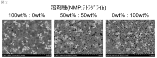
- FIG. 2 shows a surface SEM image of a moisture sensitive membrane in an embodiment of the present disclosure.
- FIG. 7 shows a correlation between the amount of tetraglyme used in a moisture sensitive membrane and the sensitivity of a humidity sensor in an embodiment of the present disclosure.
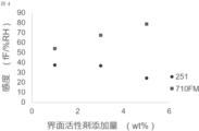
- FIG. 2 shows a correlation between the amount of surfactant used during formation of a moisture sensitive film and the sensitivity of a humidity sensor in an embodiment of the present disclosure.
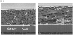
- 1 shows a cross-sectional SEM image of a moisture-sensitive membrane in an embodiment of the present disclosure.
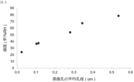
- FIG. 7 shows the correlation between the average pore diameter of the surface pores of a moisture sensitive membrane and the sensitivity of a humidity sensor in an embodiment of the present disclosure.
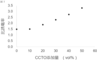
- FIG. FIG. 7 shows the correlation between the amount of CCTO filler contained in the moisture sensitive film and the dielectric constant of the porous textured moisture member in an embodiment of the present disclosure.
- FIG. 2 shows a correlation between the amount of CCTO filler contained in a moisture sensitive film and the sensitivity of a humidity sensor in an embodiment of the present disclosure.
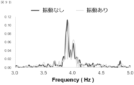
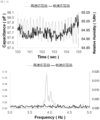
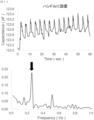
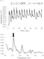
- 3 shows measurement data in a respiration sensing system in an embodiment of the present disclosure. 4 shows Fourier transform results of measurement data in a respiration sensing system in an embodiment of the present disclosure. 3 shows measurement data and Fourier transform results in a respiratory detection system in an embodiment of the present disclosure.
- FIG. 2 shows a schematic diagram of a region (cone A region) in which a humidity sensor is arranged in a respiratory detection system in an embodiment of the present disclosure.
- 3 shows measurement data and Fourier transform results in a respiratory detection system in an embodiment of the present disclosure.
- 3 shows measurement data and Fourier transform results in a respiratory detection system in an embodiment of the present disclosure.
- 3 shows measurement data and Fourier transform results in a respiratory detection system in an embodiment of the present disclosure.
- FIG. 2 shows a schematic diagram of a region (cone B region) in which a humidity sensor is arranged in a respiratory detection system in an embodiment of the present disclosure.
- 3 shows measurement data and Fourier transform results in a respiratory detection system in an embodiment of the present disclosure.
- FIG. 2 shows a schematic diagram of a region (cone C region) in which a humidity sensor is arranged in a respiratory detection system in an embodiment of the present disclosure.
- 3 shows measurement data and Fourier transform results in a respiratory detection system in an embodiment of the present disclosure.
- 3 shows measurement data and Fourier transform results in a respiratory detection system in an embodiment of the present disclosure.
- 3 shows measurement data and Fourier transform results in a respiratory detection system in an embodiment of the present disclosure.
- 3 shows measurement data in a respiration sensing system in an embodiment of the present disclosure.
- 3 shows measurement data in a respiration sensing system in an embodiment of the present disclosure.
- 3 shows measurement data in a respiration sensing system in an embodiment of the present disclosure.
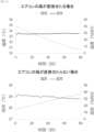
- 5 shows the correlation between temperature and humidity and time when air from an air conditioner directly hits and when air from an air conditioner does not hit directly, according to an embodiment of the present disclosure.
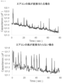
- 3 shows measurement data in a respiration sensing system in an embodiment of the present disclosure.
- the porous textured moisture member may be simply referred to as a moisture sensing member, and the humidity sensor may be simply referred to as a humidity sensor.
- porous moisture material in the present disclosure is suitably used in a humidity sensor.
- the term “member” refers to a component of the humidity sensor, and can be translated as "material,””component,””portion,””configuration,” or the like.
- the porous textured moisture member in the present disclosure includes a resin matrix and an inorganic filler.
- the porous textured moisture member is a so-called composite material, and has a porous structure in which an inorganic filler is dispersed and composited in a porous resin matrix network.
- the porous moisture material of the present disclosure as a humidity sensing member of a humidity sensor, water molecules can easily move in and out of the humidity sensing member, thereby achieving high-speed response (high-speed response and/or high-speed recovery). It is possible. Further, by using the porous textured moisture member according to the present disclosure, it is thought that the amount of water molecules adsorbed increases and the sensor sensitivity also improves.
- the shape of the porous moisture member depends on the structure of the humidity sensor used, but it is usually membrane-like or sheet-like.
- the thickness of the porous textured moisture member may be 0.5 ⁇ m or more, 1 ⁇ m or more, 2.5 ⁇ m or more, 5 ⁇ m or more, or 10 ⁇ m or more, preferably 1 ⁇ m or more.
- the thickness of the porous textured moisture member may be 1000 ⁇ m or less, 500 ⁇ m or less, 100 ⁇ m or less, 50 ⁇ m or less, 10 ⁇ m or less, or 5 ⁇ m or less, preferably 50 ⁇ m or less.
- the above range is preferable from the viewpoint of sensitivity or responsiveness of the humidity sensor.
- the porous moisture member in the present disclosure includes a large number of pores (voids).
- the pores are distributed throughout the porous moisture material, and the porous moisture material preferably includes not only surface pores but also internal pores.
- Surface pores refer to pores that are open to the outside of the porous moisture material on the surface of the porous moisture material.
- Internal pores refer to pores that exist inside the porous moisture material and are not open to the outside of the porous moisture material.
- the internal bore may be horizontally flat.
- the internal pores may communicate with adjacent pores (even if the pores communicate directly or indirectly with the surface pores, they do not directly open to the outside of the porous moisture member). (as long as it is an internal hole).
- porous makes it easier for many water molecules to be adsorbed to the moisture-sensitive member, which increases the change in the physical properties of the moisture-sensitive member due to changes in humidity, which can improve sensitivity.
- Including surface pores and internal pores may improve the sensitivity or responsiveness of the humidity sensor.
- the average pore diameter of the surface pores may be 0.1 ⁇ m or more, 0.5 ⁇ m or more, 1 ⁇ m or more, 3 ⁇ m or more, or 5 ⁇ m or more, preferably 1 ⁇ m or more.
- the average pore size of the surface pores may be 50 ⁇ m or less, 25 ⁇ m or less, 10 ⁇ m or less, 5 ⁇ m or less, 2.5 ⁇ m or less, 1.2 ⁇ m or less, 0.6 ⁇ m or less, or 0.2 ⁇ m or less.
- the average pore diameter of the surface pores may be 1/2 or less, 1/3 or less, 1/4 or less, or 1/5 or less of the thickness of the porous textured moisture member from the viewpoint of adhesion to the base material.
- the above range is preferable from the viewpoint of sensitivity or responsiveness of the humidity sensor.
- the large pore size allows water molecules to move in and out easily, improving responsiveness, and also allows water molecules to be adsorbed in multiple layers on the pore surface, improving sensitivity.
- the average pore diameter of the surface pores can be determined by microscopic observation. The surface of the porous moisture material can be observed with a microscope, and the longest diameter of each observed surface pore can be regarded as the pore diameter of each surface pore. The pore diameters of all surface pores existing within the field of view are measured, the field of view is moved and the pore diameters are measured again, and the average value of 100 or more is taken as the average pore diameter of the surface pores.
- the density of surface pores is 1/100 ⁇ m 2 or more, 5/100 ⁇ m 2 or more, 10/100 ⁇ m 2 or more, 50/100 ⁇ m 2 or more, 100 pieces/100 ⁇ m 2 or more, 250 pieces/100 ⁇ m 2 or more, 500 pieces/100 ⁇ m 2 or more, or 750 pieces/100 ⁇ m 2 or more, preferably 50 pieces/100 ⁇ m 2 or more, more preferably 250 pieces /100 ⁇ m 2 or more.
- Pore diameter of 0.1 ⁇ m or more (the pore diameter is 1/2 or less, 1/3 or less, 1/4 or less, or 1/5 or less of the thickness of the porous textured moisture member, or 10 ⁇ m or less, 5 ⁇ m or less, 2.5 ⁇ m or less, or 1 ⁇ m or less, in particular 10 ⁇ m or less or 5 ⁇ m or less ) . or less, or 100 pieces/100 ⁇ m 2 or less.
- the above range is preferable from the viewpoint of sensitivity or responsiveness of the humidity sensor.
- the large pore size allows water molecules to move in and out easily, improving responsiveness, and also allows water molecules to be adsorbed in multiple layers on the pore surface, improving sensitivity.
- the density of the surface pores can be determined by measuring the density of the surface pores from a microscopic image of the surface of the porous moisture member having a field of view of at least 100 ⁇ m 2 or more.
- a pore cross section is present in any cross section of the porous textured moisture member.
- the cross section may be a thickness direction cross section (vertical direction cross section).
- the cross-sectional diameter of the pore cross section present may be 0.1 ⁇ m or more, 0.5 ⁇ m or more, 1 ⁇ m or more, 2 ⁇ m or more, 3 ⁇ m or more, 4 ⁇ m or more, or 5 ⁇ m or more, preferably 1 ⁇ m or more.
- the diameter of the cross section of the pores present may be less than or equal to 2/3, less than or equal to 1/2 of the thickness of the porous textured moisture member, or less than or equal to 50 ⁇ m, less than or equal to 25 ⁇ m, less than or equal to 10 ⁇ m, less than or equal to 7.5 ⁇ m, or less than or equal to 5 ⁇ m, preferably less than or equal to 5 ⁇ m. It is 10 ⁇ m or less.
- the above range is preferable from the viewpoint of sensitivity or responsiveness of the humidity sensor.
- the large pore size allows water molecules to move in and out easily, improving responsiveness, and also allows water molecules to be adsorbed in multiple layers on the pore surface, improving sensitivity.
- the cross-sectional diameter of the pores in the cross-section of the porous moisture material can be determined by microscopic observation. By observing the pore cross-section with a microscope, the longest diameter of each pore cross-section observed can be regarded as the cross-sectional diameter of each pore cross-section.
- Methods for cross-sectional observation include vertically embedding a porous moisture material in epoxy resin, mechanically polishing the embedded surface, and then observing it with a SEM (scanning electron microscope) or using an FIB (focused ion beam) device. For example, a method of cutting out a specimen for observation so that the cross section of the porous moisturizing member can be seen and observing the cross section using a SEM (scanning electron microscope), etc. can be mentioned.
- the cross-sectional diameter is 1 ⁇ m or more (the cross-sectional diameter is 2/3 or less, 1/2 or less of the thickness of the porous textured moisture member, or 10 ⁇ m or less, 5 ⁇ m or less, or 2.5 ⁇ m or less , or 1 ⁇ m or less, in particular 10 ⁇ m or less), the density of the pore cross section is 10/100 ⁇ m 2 or more, 20/100 ⁇ m 2 or more, 30/100 ⁇ m 2 or more, 40/100 ⁇ m 2 or more, 50 The number may be 2 or more pieces/100 ⁇ m 2 or more, 60 pieces/100 ⁇ m 2 or more, or 70 pieces/100 ⁇ m 2 or more, and preferably 50 pieces/100 ⁇ m 2 or more .
- the cross-sectional diameter is 1 ⁇ m or more (the cross-sectional diameter is 2/3 or less, 1/2 or less of the thickness of the porous textured moisture member, or 10 ⁇ m or less, 5 ⁇ m or less, 2.5 ⁇ m or less, or
- the density of the pore cross section (which may be 1 ⁇ m or less, in particular 10 ⁇ m or less) is 100 pores/100 ⁇ m 2 or less, 90 pores/100 ⁇ m 2 or less, 80 pores/100 ⁇ m 2 or less, or 70 pores/100 ⁇ m 2 or less.
- the cross section may be a thickness direction cross section (vertical direction cross section). The above range is preferable from the viewpoint of sensitivity or responsiveness of the humidity sensor.
- the large pore size allows water molecules to move in and out easily, improving responsiveness, and also allows water molecules to be adsorbed in multiple layers on the pore surface, improving sensitivity.
- the density of the pore cross section can be determined by measuring the density of the pore cross section from a cross section of the porous moisture member having a field of view of at least 100 ⁇ m 2 or more.
- the specific surface area of the porous moisture material is 0.1 m 2 /g or more, 0.5 m 2 /g or more, 1 m 2 /g or more, 2 m 2 /g or more, 3 m 2 /g or more, 5 m 2 / g or more, or 7 .5 m 2 /g or more.
- the specific surface area of the porous textured moisture member may be 50 m 2 /g or less, 20 m 2 /g or less, 10 m 2 /g or less, 5 m 2 /g or less, 2 m 2 /g or less, or 1.5 m 2 /g or less. , preferably 2 m 2 /g or less.
- the above range is preferable from the viewpoint of sensitivity or responsiveness of the humidity sensor.
- the specific surface area can be determined by the BET method.
- the porosity of the porous moisture material is 5% by volume or more, 10% by volume or more, 20% by volume or more, 30% by volume or more, 40% by volume or more, or 50% by volume or more, 60% by volume or more, 70% by volume or more, It may be 80 volume% or more, or 90 volume% or more, preferably 10 volume% or more, or 30 volume% or more, more preferably 60 volume% or more.
- the porosity of the porous moisture material is 99% by volume or less, 90% by volume or less, 80% by volume or less, 70% by volume or less, 60% by volume or less, 50% by volume or less, 40% by volume or less, or 30% by volume or less. It may be present, preferably 90% by volume or less.
- the above range is preferable from the viewpoint of sensitivity or responsiveness of the humidity sensor.
- the large porosity makes it easier for water molecules to move in and out, improving the responsiveness of the humidity sensor, and the sensitivity can also be improved because water molecules can be adsorbed in multiple layers on the pore surface.
- the porosity is defined as the ratio of the volume of pores to the total volume of the porous moisture material, and the porosity can be determined by optical methods, water evaporation methods, SEM image observation, Archimedes method, etc.
- the relative dielectric constant of the porous textured moisture member is 1.2 or more, 1.4 or more, 1.6 or more, 1.8 or more, 2.0 or more, 2.2 or more, 2.4 or more, 2.7 or more, It may be 3.0 or more, or 3.3 or more, and the higher the value, the more preferable.
- the dielectric constant of the porous textured moisture member may be 100 or less, 80 or less, 60 or less, 40 or less, 20 or less, 10 or less, 7.5 or less, or 5.0 or less. The above range is preferable from the viewpoint of sensitivity or responsiveness of the humidity sensor. It is thought that the higher the dielectric constant of the porous moisture-sensitive member, the more water molecules can be adsorbed, and the greater the change in the physical properties of the moisture-sensitive member due to changes in humidity, which can improve the sensitivity.
- the resin matrix may be a thermoplastic resin, a thermoset resin, or a combination thereof.
- the resin matrix may be a homopolymer, a copolymer such as a star block copolymer, a graft copolymer, an alternating block copolymer, a random copolymer, an ionomer, a dendrimer, and the like.
- resin base materials include polyamide, polyimide, polyamideimide, polyurethane, polyether, polyetherimide, polyetherketone, polycarbonate, polyester, polyacrylic, polyolefin, polyvinyl alcohol, polyvinyl halide, polysiloxane, and modified cellulose.
- aromatic polyimide aromatic polyamideimide
- aromatic polyamide aromatic polyether
- polyethylene terephthalate polyethylene terephthalate
- cellulose acetate butyrate CAB
- PMMA polymethyl methacrylate
- vinyl crotonate etc. These may be used alone or in combination of two or more.
- the resin base material may have high hygroscopicity from the viewpoint of enhancing the interaction with water molecules of the porous moisture member and improving the sensitivity and responsiveness of the humidity sensor.
- resins containing highly polar groups such as amino groups, carboxy groups, hydroxyl groups, phosphoric acid groups, sulfonic acid groups, nitrile groups, especially groups capable of forming hydrogen bonds, especially amide groups or imide groups. It may be resin.
- the amount of the resin matrix is 10% by weight or more, 20% by weight or more, 30% by weight or more, 40% by weight or more, 50% by weight or more, 60% by weight or more, or 70% by weight or more with respect to the porous textured moisture member. 50% by weight or more is preferred.
- the amount of the resin matrix is 99% by weight or less, 90% by weight or less, 80% by weight or less, 70% by weight or less, 60% by weight or less, 50% by weight or less, 40% by weight or less, based on the porous textured moisture member. Or it may be 30% by weight or less.
- the amount of the resin base material is 5% by volume or more, 10% by volume or more, 15% by volume or more, 20% by volume or more, 25% by volume or more, 30% by volume or more, or 50% by volume or more with respect to the porous moisture material. 20% by volume or more is preferred.
- the amount of the resin matrix is 75% by volume or less, 60% by volume or less, 50% by volume or less, 40% by volume or less, 30% by volume or less, 20% by volume or less, or 10% by volume or less with respect to the porous moisture material. It may be.
- the inorganic filler may be particulate (spherical, flaky, plate-like, etc.).
- the average particle size of the inorganic filler may be 50 nm or more, 100 nm or more, 300 nm or more, 500 nm or more, or 1000 nm or more.
- the average particle size of the inorganic filler may be 10000 nm or less, 5000 nm or less, 3000 nm or less, 1000 nm or less, or 500 nm or less.
- the average particle size of the inorganic filler can be determined by microscopic observation.
- An inorganic filler can be observed with a microscope, and the longest diameter of the observed inorganic filler can be considered as the particle size of each inorganic filler.
- the particle sizes of all inorganic fillers present within the field of view are measured, the field of view is moved and the particle sizes are measured again, and the average value is taken as the average particle size of the inorganic filler particles.
- inorganic fillers include ceramic fillers, metal fillers, and the like.
- ceramic fillers include silica, alumina, mica, talc, titania, titanates (potassium titanate, barium titanate, bismuth titanate, magnesium titanate, etc.), zirconia, zirconate, zinc oxide, oxide Oxide fillers such as iron and ferrite; Hydroxide fillers such as aluminum hydroxide and hydroxyapatite; Carbide fillers such as silicon carbide, aluminum carbide, and calcium carbide; Nitride fillers such as silicon nitride and aluminum nitride; Carbonate fillers such as calcium carbonate and magnesium carbonate; Sulfate fillers such as barium sulfate and aluminum sulfate; Phosphate fillers such as calcium phosphate and aluminum phosphate; Halogens such as aluminum fluoride, carbon fluoride, and fluorite Compound fillers include carbon fillers such as carbon black, graphite, graphene, and carbon
- the inorganic filler may be a material with a dipole moment, such as a ferroelectric, or a material with oxygen vacancies.
- the inorganic filler may include a high dielectric material.
- the dielectric constant of the high dielectric material at 25° C. and 1 kHz may be 5 or more, 10 or more, 100 or more, 500 or more, or 1000 or more.
- Such inorganic fillers include barium titanate (BaTiO 3 ), strontium titanate (SrTiO 3 ), strontium barium titanate, strontium-doped lanthanum manganate, lanthanum aluminum oxide (LaAlO 3 ), and lanthanum copper strontium oxide (LSCO).
- the inorganic filler may include a material having a perovskite structure.
- a perovskite structure ideally has a cubic crystal unit cell, with metal A placed at each vertex of the cubic crystal, metal B placed at the body center, and metal B placed at each face center of the cubic crystal. It has an ABO 3 type crystal structure composed of oxygen and O.
- the perovskite structure also includes tetragonal, orthorhombic, rhombohedral, etc., which are distorted cubic crystals.
- the inorganic filler may be surface-modified with a surface treatment agent (for example, a silane coupling agent). Inorganic fillers may be used alone or in combination of two or more.
- the amount of the inorganic filler is 1% by weight or more, 10% by weight or more, 20% by weight or more, 30% by weight or more, 40% by weight or more, 50% by weight or more, 60% by weight or more, 70% by weight or more, based on the porous textured moisture member. It may be at least 30% by weight, at least 80% by weight, or at least 90% by weight, and from the viewpoint of sensitivity or responsiveness of the humidity sensor, preferably at least 30% by weight, more preferably at least 50% by weight, especially at least 70% by weight. be.
- the amount of the inorganic filler is 99% by weight or less, 90% by weight or less, 80% by weight or less, 70% by weight or less, 60% by weight or less, 50% by weight or less, 40% by weight or less, or It may be 30% by weight or less.
- the amount of inorganic filler is 1% by weight or more, 10% by weight or more, 20% by weight or more, 30% by weight or more, 40% by weight or more, 50% by weight or more, 60% by weight or more, 70% by weight based on the resin base material. % or more, 80% by weight or more, or 90% by weight or more, and from the viewpoint of sensitivity or responsiveness of the humidity sensor, preferably 30% by weight or more, more preferably 50% by weight or more, and especially 70% by weight or more. .
- the amount of the inorganic filler is 99% by weight or less, 90% by weight or less, 80% by weight or less, 70% by weight or less, 60% by weight or less, 50% by weight or less, 40% by weight or less, or 30% by weight or less, based on the resin base material. It may be less than % by weight.
- the amount of the inorganic filler may be 1% by volume or more, 10% by volume or more, 20% by volume or more, 30% by volume or more, 40% by volume or more, or 50% by volume or more with respect to the resin base material. From the viewpoint of sensitivity or responsiveness, it is preferably 10 volume % or more, 30 volume % or more, or 50 volume % or more.
- the amount of inorganic filler is 99% by volume or less, 90% by volume or less, 80% by volume or less, 70% by volume or less, 60% by volume or less, 50% by volume or less, 40% by volume or less, or 30% by volume or less, based on the resin base material. It may be less than or equal to % by volume.
- the porous textured moisture member may include a surfactant.
- a surfactant By including a surfactant, the pore size and pore density can be adjusted.
- surfactants include anionic, cationic, amphoteric, and nonionic surfactants.
- the surfactant may include a fluorosurfactant. By containing a fluorine-based surfactant, water repellency, oil repellency, stain resistance, etc. can be imparted, and good sensitivity and responsiveness of the humidity sensor can be provided. Also, by using a hydrophobic ionic surfactant, larger sized pores can be formed. Surfactants may be used alone or in combination of two or more.
- the amount of surfactant is 0.1% by weight or more, 0.5% by weight or more, 1% by weight or more, 2% by weight or more, 3% by weight or more, 4% by weight or more, or It may be 5% by weight or more, preferably 1% by weight or more.
- the amount of surfactant may be 25% or less, 20% or less, 15% or less, 10% or less, or 7.5% or less by weight of the porous textured moisture member.
- the amount of surfactant is 0.1% by weight or more, 0.5% by weight or more, 1% by weight or more, 2% by weight or more, 3% by weight or more, 4% by weight or more, or 5% by weight based on the inorganic filler. % or more, preferably 1% or more by weight.
- the amount of surfactant may be 25% or less, 20% or less, 15% or less, 10% or less, or 7.5% or less by weight relative to the inorganic filler.
- the porous moisturizing member in the present disclosure may include or be treated with a silane coupling agent.
- the porous moisture material contains a silane coupling agent or is treated with a silane coupling agent, the adhesion between the resin matrix and the inorganic filler can be improved, resulting in good sensitivity and responsiveness of the humidity sensor.
- silane coupling agent is not particularly limited, but examples include vinyltrimethoxysilane, vinyltriethoxysilane, vinyltris(2-methoxyethoxy)silane, allyltrichlorosilane, allyltrimethoxysilane, allyltriethoxysilane, diethoxymethyl Vinyl silane coupling agents such as vinylsilane, trichlorovinylsilane, triethoxyvinylsilane; 2-(3,4-epoxycyclohexyl)ethyltrimethoxysilane, 3-glycidoxypropyltrimethoxysilane, 3-glycidoxypropyltriethoxy Epoxy-based silane coupling agents such as silane; methacryloxymethyltrimethoxysilane, methacryloxymethyltriethoxysilane, methacryloxymethylmethyldimethoxysilane, methacryloxymethyldimethylmethoxysilane, ⁇ -methacryloxyprop
- the amount of the silane coupling agent is 0.1% by weight or more, 0.5% by weight or more, 1% by weight or more, 2% by weight or more, 3% by weight or more, 4% by weight or more, based on the porous textured moisture member. Or it may be 5% by weight or more, preferably 1% by weight or more.
- the amount of silane coupling agent may be 25% or less, 20% or less, 15% or less, 10% or less, or 7.5% or less by weight of the porous moisture member.
- the amount of the silane coupling agent is 0.1% by weight or more, 0.5% by weight or more, 1% by weight or more, 2% by weight or more, 3% by weight or more, 4% by weight or more, or 5% by weight or more based on the inorganic filler. It may be at least 1% by weight, preferably at least 1% by weight. The amount of silane coupling agent may be 25% by weight or less, 20% by weight or less, 15% by weight or less, 10% by weight or less, or 7.5% by weight or less based on the inorganic filler.
- ingredients Other components may be added to the porous textured moisture member.
- other ingredients include plasticizers, lubricants, colorants (pigments, dyes, etc.), ultraviolet absorbers, antioxidants, anti-aging agents, foaming agents, defoamers, reinforcing agents, flame retardants, and antistatic agents. agent, surfactant, surface treatment agent, water repellent, oil repellent, antifouling agent, etc. These may be used alone or in combination of two or more.
- the amounts of other components can be appropriately selected within a range that does not impair the effects of the present disclosure.
- the amount of each other component is 0.1% by weight or more, 0.3% by weight or more, 0.5% by weight or more, 0.7% by weight or more, or 1% by weight or more with respect to the porous moisture material. It's fine.
- the amount of other components may be 10% by weight or less, 7.5% by weight or less, 5% by weight or less, 3% by weight or less, 2% by weight or less, or 1% by weight or less based on the porous textured moisture member. .
- the method for manufacturing a porous textured moisture member may include a dispersion liquid preparation step and a coating drying step.
- a resin base material, an inorganic filler, and other components as necessary are dispersed in a solvent to obtain a dispersion.
- the resulting dispersion is coated on a base material (for example, a substrate, an electrode) and further dried to obtain a porous textured moisture member.
- a foaming agent may be used as a component of the dispersion.
- the solvent for the dispersion it is possible to use a solvent that can dissolve the resin, but from the viewpoint of obtaining a porous wet material with good pore density, it contains an ether solvent, especially a glycol ether solvent. It is preferable.
- the amount of ether solvent may be 10% or more, 30% or more, 50% or more, or 60% or more, preferably 30% or more, by weight of the solvent.
- the amount of ethereal solvent may be 70% or less, 60% or less, 50% or less, or 40% or less, 30% or less, or 20% or less by weight of the solvent.
- the present disclosure further provides a humidity sensor.
- the humidity sensor in the present disclosure includes: a first electrode; a second electrode; A porous moisture member may be provided between the first electrode and the second electrode.
- the physical properties change when the porous moisture material absorbs moisture, and the electrical characteristics between the first and second electrodes change depending on the amount of moisture (i.e. humidity) contained in the atmosphere of the surrounding environment. It functions as a humidity sensor based on the principle that the humidity changes.
- the humidity sensor of the present disclosure since the porous moisture member of the present disclosure has excellent water adsorption/desorption properties, the humidity sensor of the present disclosure has excellent sensitivity and responsiveness.
- the humidity sensor in the present disclosure may be of a variable resistance type or a variable capacitance type.
- a variable resistance humidity sensor measures a change in resistance of a humidity sensitive member due to a change in humidity
- a variable capacitance humidity sensor measures a change in capacitance of a humidity sensitive member due to a change in humidity.
- the humidity sensor according to the present disclosure is particularly suitable as a capacitance variable humidity sensor from the viewpoint of performance such as sensitivity and responsiveness.
- the humidity sensor may include a substrate, and a first electrode may be formed on the substrate, so that the first electrode and the porous moisture member are in contact with each other.
- the porous moisture material includes a substrate, a first electrode formed on the substrate, a porous moisture material formed on the first electrode, and a second porous moisture material formed on the porous moisture material. Two electrodes may be provided.
- a humidity sensor in another embodiment, includes a substrate, first and second electrodes formed on the substrate, and a porous moisture member provided between the first and second electrodes. Good too.
- a humidity sensor may include a substrate, a porous moisture material formed on the substrate, and first and second electrodes formed on the porous moisture material.
- the first electrode and the second electrode may be a comb-shaped electrode.
- the first electrode and the second electrode may be arranged as comb-shaped electrodes so as to face each other so as to mesh with each other.
- the humidity sensor when using a comb-shaped electrode, the humidity sensor includes a substrate, a first electrode and a second electrode formed on the substrate, and a porous member provided between the first electrode and the second electrode. It may also have.
- the first electrode may be formed by a vapor deposition method, a sputtering method, an ion plating method, a screen printing method, or the like.
- the porous textured moisture member may be formed by coating, screen printing, or the like.
- the second electrode may be formed by a vapor deposition method, a sputtering method, an ion plating method, a screen printing method, or the like.
- the present disclosure further provides a breath sensing system.
- a breathing detection system refers to a system that detects a subject's breathing using a sensor, and the breathing detection system in the present disclosure uses a humidity sensor.
- the humidity sensor it is preferable to use the humidity sensor according to the present disclosure described above.
- the respiration detection system of the present disclosure uses a humidity sensor, it is less susceptible to the effects of vibration, which is advantageous compared to sensors that are easily affected by vibrations, such as sensors including millimeter wave sensors and cameras. Further, since the humidity sensor including the porous textured moisture member of the present disclosure exhibits good sensitivity and response speed, a respiration detection system using the humidity sensor including the porous textured moisture member of the present disclosure is less susceptible to wind effects and is suitable for air conditioning equipment. It can be used well even in spaces with large spaces.
- the direct measurement data obtained from the respiratory detection results of the respiratory detection system in the present disclosure is a function of a time variable, it can be converted into a function of a frequency variable by using Fourier transform, and from the peak frequency to the respiratory detection result. be able to identify the number.
- the Fourier transform method is well known to those skilled in the art, and the conditions thereof can be appropriately determined by those skilled in the art. For example, the sampling interval is 50 ms and the number of samples is 1024.
- the source of exhaled air is the subject's mouth or nostrils.
- Front direction is usually the subject's direction of travel or line of sight.
- vertically upward direction may correspond to the "upward direction”
- opposite direction may correspond to the "downward direction.”
- the respiratory detection system in the present disclosure preferably uses a humidity sensor that uses the porous moisture member described above.
- the total response time and recovery time of the humidity sensor used in the respiratory detection system of the present disclosure may be 0 seconds or more, 0.1 seconds or more, 0.5 seconds or more, or 1 second or more.
- the total response time and recovery time of the humidity sensor used in the respiration detection system of the present disclosure is 25 seconds or less, 20 seconds or less, 15 seconds or less, 10 seconds or less, 8 seconds or less, 5 seconds or less, 3 seconds or less, or It may be 2 seconds or less, preferably 10 seconds or less, more preferably 5 seconds or less. Therefore, the shorter the total response time and recovery time (higher responsiveness), the more accurately respiration can be measured.
- the methods for measuring response time and recovery time are as described in Examples.
- the sensitivity of the humidity sensor used in the respiratory detection system of the present disclosure may be 10 or more, 20 or more, 30 or more, 50 or more, 100 or more, 200 or more, 300 or more, or 500 or more, preferably 30 or more.
- the sensitivity of the humidity sensor used in the respiration sensing system of the present disclosure may be 3000 or less, 2000 or less, 1000 or less, 500 or less, or 250 or less.
- the method for measuring sensitivity is as described in Examples.
- a humidity sensor is placed in a specific area to suitably detect respiration.
- the area where the humidity sensors are placed may mean the area where a part or all of each humidity sensor is placed, for example, the area where the center of gravity of the humidity sensor is placed. .
- sensors examples include car steering wheels, seat belts, necklaces, pet collars and harnesses, computers, keyboards, mice, televisions, game controllers, wristwatches, smart watches, mobile phones, smartphones, chests, etc. Examples include arms, neck, abdomen, lower back, bed, pillow, etc.
- a location such as a wristwatch whose position relative to the subject is not necessarily fixed may be selected. The subject may actively blow into the humidity sensor to measure respiration.
- the area where the humidity sensor is placed may be within the spherical area.
- the sphere is centered on the subject's exhaled air source.
- the radius of the sphere may be 0 cm or more, 3 cm or more, 5 cm or more, 10 cm or more, 15 cm or more, 20 cm or more, 25 cm or more, or 25 m or more.
- the radius of the sphere may be ⁇ 150 cm, ⁇ 140 cm, ⁇ 120 cm, ⁇ 100 cm, ⁇ 80 cm, ⁇ 70 cm, ⁇ 60 cm, ⁇ 40 cm, or ⁇ 20 cm, preferably ⁇ 100 cm, especially ⁇ 70 cm.
- the area where the humidity sensor is placed may be an area other than the 1/4 sphere area on the upper back surface of the sphere. That is, the area where the humidity sensor is placed may be the upper front side, the lower front side, or the lower back side of the sphere. By selecting the above area as the area where the humidity sensor is placed, good measurement results are likely to be obtained.
- the straight-line distance between the humidity sensor installed in the spherical region and the exhalation source may be 0 cm or more, 3 cm or more, 5 cm or more, 7 cm or more, 10 cm or more, or 15 cm or more, or 20 cm or more, and a specific exhalation source is selected. From the viewpoint of effective detection, the length is preferably 5 cm or more or 10 cm or more.
- the area where the humidity sensor is placed may be the cone A area.
- the cone A has an apex as the subject's exhalation source, and a rotation axis as a straight line extending from the exhalation source to the front direction of the subject.
- FIG. 11 shows a schematic diagram of the cone A region in the respiratory detection system.
- the area within the cone 6 in FIG. 11, preferably the colored truncated cone area, can be the area where the humidity sensor is placed.
- the height of the uncolored cone located at the top of the cone 6 can be the minimum linear distance between the humidity sensor and the exhaled air source.
- the cone angle defined by the apex angle of the isosceles triangle formed when cone A is cut by a plane passing through the axis of rotation is 0° or more, 3° or more, 5° or more, 8° or more, or 10° or more. good.
- the cone angle defined by the apex angle of the isosceles triangle created when cone A is cut by a plane passing through the axis of rotation is 90° or less, 60° or less, 40° or less, 35° or less, 30° or less, 25° or less , 20° or less, or 15° or less, preferably 40° or less.
- the cone height defined by the straight line length from the center of the base to the apex may be 150 cm or less, 120 cm or less, 100 cm or less, 90 cm or less, 70 cm or less, 50 cm or less, 30 cm or less, or 20 cm or less. , preferably 100 cm or less, particularly 70 cm or less.
- the straight-line distance between the humidity sensor placed in the conical region A and the exhalation source may be 0 cm or more, 3 cm or more, 5 cm or more, 7 cm or more, or 10 cm or more, preferably 5 cm or more. By selecting the above range as the straight-line distance, good measurement results are likely to be obtained.
- the humidity sensor is disposed within the cone A region, mouth breathing components can be detected more selectively by providing a certain distance between the humidity sensor and the exhaled air source.
- the source of exhaled air may be the subject's mouth or nostrils, preferably the subject's mouth.
- the breath sensing system is suitable for detecting mouth breath components.
- suitable installation locations include a steering wheel, a personal computer, a television, and the like.
- the area where the humidity sensor is placed may be the cone B area.
- the cone B has an apex as the exhalation source and a rotation axis as a straight line extending from the exhalation source in a direction of 30 degrees downward and 30 degrees to the right or left with the back direction as a reference.
- FIG. 15 shows a schematic diagram of the cone B region of the humidity sensor in the respiratory detection system.
- the area within the cone 14 or 14' in FIG. 15, preferably within the colored truncated cone area, may be the area where the humidity sensor is placed.
- the height of the uncolored cone located at the top of the cone 14 or 14' may be the minimum linear distance between the humidity sensor and the source of exhaled air.
- the cone angle defined by the apex angle of the isosceles triangle formed when cone B is cut by a plane passing through the axis of rotation is 0° or more, 3° or more, 5° or more, 8° or more, or 10° or more. good.
- the cone angle defined by the apex angle of the isosceles triangle formed when cone B is cut by a plane passing through the axis of rotation is 90° or less, 80° or less, 60° or less, 40° or less, 35° or less, 30° or less , 25° or less, 20° or less, or 15° or less, preferably 60° or less.
- cone B the cone height defined by the straight line length from the center of the base to the apex is 150 cm or less, 120 cm or less, 100 cm or less, 90 cm or less, 70 cm or less, 50 cm or less, 30 cm or less, 20 cm or less, or 10 cm or less.
- the length may be 30 cm or less, preferably 30 cm or less.
- the straight-line distance between the humidity sensor placed in the conical region B and the exhalation source may be 0 cm or more, 3 cm or more, 5 cm or more, 7 cm or more, or 10 cm or more, preferably 5 cm or more.
- the exhaled air source may be the subject's mouth and/or nostrils.
- the respiratory detection system is suitable for detecting mouth breathing components and/or nasal breathing components.
- suitable installation locations include a necklace, a pet's collar or harness, and the neck.
- the area where the humidity sensor is placed may be the conical C area.
- the cone C has an apex as the exhalation source and a rotation axis as a straight line extending downward from the exhalation source to the subject.
- FIG. 17 shows a schematic diagram of the conical region C of the humidity sensor in the respiratory detection system.
- the area within the cone 20 in FIG. 17, preferably within the colored truncated cone area, can be the area where the humidity sensor is placed.
- the height of the uncolored cone located at the top of the cone 20 may be the minimum linear distance between the humidity sensor and the exhaled air source.
- the cone angle defined by the apex angle of the isosceles triangle formed when the cone C is cut by a plane passing through the axis of rotation is 0° or more, 3° or more, 5° or more, 8° or more, or 10° or more. good.
- the cone angle defined by the apex angle of the isosceles triangle created when cone C is cut by a plane passing through the axis of rotation is 90° or less, 80° or less, 60° or less, 40° or less, 35° or less, 30° or less , 25° or less, 20° or less, or 15° or less, preferably 60° or less.
- the cone height defined by the straight line length from the center of the base to the apex may be 150 cm or less, 120 cm or less, 100 cm or less, 90 cm or less, 70 cm or less, 50 cm or less, 30 cm or less, or 20 cm or less. , preferably 70 cm or less.
- the straight-line distance between the humidity sensor disposed within the conical region C and the exhalation source may be 0 cm or more, 3 cm or more, 5 cm or more, 7 cm or more, 10 cm or more, 15 cm or more, or 20 cm or more, preferably 5 cm or more, or more. Preferably it is 10 cm or more. By selecting the above range as the straight-line distance, good measurement results are likely to be obtained.
- nasal respiratory components can be detected more selectively by providing a certain distance between the humidity sensor and the exhalation source.
- the exhaled air source may be the subject's mouth or nostrils, preferably the subject's nostrils.
- the respiratory detection system is suitable for detecting nasal respiratory components.
- suitable installation locations include the seat belt, neck, abdomen, waist, etc.
- the spherical region, conical A region, conical B region, and conical C region are shown as examples of the installation locations of the humidity sensor, but the installation locations are not limited to the above. Furthermore, it is also possible to install one or more sensors in one or more of the spherical region, the cone A region, the cone B region, and the cone C region.
- the combinations include a combination of a cone A area and a cone B area, a combination of a cone A area and a cone C area, a combination of a cone B area and a cone C area, a cone A area, a cone B area, and a cone C area.
- cone A area is suitable for detecting mouth breathing
- cone C area is suitable for detecting nasal breathing
- the mouth breathing component and the nasal breathing component can be detected. May be measured separately.
- the nose acts as a filter to remove bacteria and viruses from the air, and humidified and warmed air is taken into the lungs through the nose, so it is generally said that breathing through the nose is a better way to breathe. ing. Therefore, by knowing whether you breathe through your mouth or through your nose, you can correct your breathing to improve your breathing.
- the respiration sensing system in the present disclosure may include a controller responsive to respiration sensing results.
- the control unit can control the equipment.
- the device is a device connected directly or indirectly to the humidity sensor. Examples of devices include, but are not limited to, automobiles, air conditioners, medical devices, other industrial devices, home appliances, and the like.
- Device control includes pausing and resuming device functions, changing device functions, changing the intensity of device functions, controlling device power ON/OFF, and generating warning signals (displaying warnings, emitting warning sounds, etc.). occurrence, vibration alarm occurrence), etc.
- examples of controlling the device include generating a warning sound, braking, slowing down, changing direction, and executing automatic driving.
- examples of device control include adjusting the environmental temperature, adjusting the environmental humidity, adjusting the air volume, adjusting the comfort by changing the wind direction, etc. (automatic adjustment).
- the respiration sensing system of the present disclosure can be used to adjust the subject's surrounding environment (temperature, humidity, etc.).
- the control unit can control the surrounding environment of the subject using the air conditioning equipment based on the breathing detection result and, if necessary, the subject's surrounding environment information, thereby improving the comfort of the subject. For example, by installing a humidity sensor on the seat belt of each seat, the temperature and humidity around each seat can be constantly measured, and when combined with HVAC, the air conditioner can be controlled to improve the comfort inside the car. It can be improved.
- respiration detection system of the present disclosure it is possible to detect the condition of the occupant or driver using information on respiration detected inside the vehicle (for example, from the steering wheel or seat belt).
- respiration detected inside the vehicle for example, from the steering wheel or seat belt.
- accidents caused by the deterioration of the health of passengers and drivers have become a problem, such as deterioration of the driver's health while driving, sudden death, and children being left behind.
- a detection system we can learn about the condition of the occupants and driver, and if necessary, control the vehicle by emitting a warning sound or safely parking the vehicle on the side of the road. Become.
- the breathing detection system in the present disclosure may further include a sensor that measures second vibration data including a second vital sign other than breathing.
- sensors that measure second vibration data including second vital signs other than breathing include optical sensors (visible light sensors, infrared sensors, etc.), sound sensors, electrical conductivity sensors, potential sensors, pressure sensors, and thermal sensors. Examples include sensors.
- the sensor that measures the second vibration data including the second vital sign other than respiration may be a sensor in which respiration is affected by vibrations, such as an optical sensor.
- Examples of second vital signs other than breathing include pulse, heart rate, body temperature, blood pressure, etc.
- the second vital sign can be detected by subtracting the first vibration data based on the respiration detection result from the second vibration data.
- a millimeter wave sensor will be described as an example of a sensor that measures second vibration data including a second vital sign. The idea is similar for other sensors as well. Millimeter wave sensors are known to be able to measure not only breathing but also heartbeat.
- the respiratory component includes not only the fundamental wave, which is the actual respiratory rate, but also harmonic components. Generally, the heart rate is faster than the respiration rate, so when attempting to accurately measure the heartbeat, the harmonic components of respiration also become a noise source (see Equation 1 below).
- the response of the humidity sensor includes the fundamental wave and harmonic components of breathing.
- the evaluation of the fabricated humidity sensor is as follows. Using a FDC2214EVM (manufactured by Texas Instruments) circuit, we measured the change in capacitance of the humidity sensor when the humidity changed. Humid air created with a bubbler is flowed at a flow rate of 1 SLM through a pipe with an inner diameter of 4 mm to a humidity sensor that has been stabilized in a humidity atmosphere of 50% RH. The distance between the humidity sensor and the piping at this time was 10 mm.
- Example 1 A case will be explained in which polyamideimide (PAI) is used as the base material of the moisture-sensitive film and Ni is used as the inorganic filler.
- PAI polyamideimide
- Ni tetraglyme
- NMP N-methyl-2-pyrrolidone
- TEGM tetraglyme
- the Ni filler used had an average particle size of about 300 nm. These raw materials were weighed so that the Ni content was 0 to 50 vol%, and mixed using a Huber muller so that the Ni filler was uniformly dispersed in the varnish.
- the varnish prepared in this way was applied by screen printing onto a 200 nm thick NiCr lower electrode formed by sputtering on a Kapton substrate, and then dried in air at 150°C for 5 minutes to form a porous polyamide-imide matrix. A moisture-sensitive film with Ni filler dispersed in the material was formed. Thereafter, a 70 nm thick upper electrode was formed by sputtering.
- Figure 1 shows the sensitivity and responsiveness of the produced humidity sensor. From FIG. 1, it can be confirmed that the sensitivity is improved in all cases when Ni is added compared to when Ni is not added. Furthermore, in terms of responsiveness, it can be seen that better characteristics can be obtained when Ni is added. These results show that dispersing Ni filler in the porous PAI matrix improves sensor characteristics in terms of sensitivity and response. In the case of the existing product, the response time was 4.1 seconds, the recovery time was 32.1 seconds, and the total time was 36.2 seconds. It can be seen that the responsiveness of existing products is overwhelmingly poor because a non-porous resin material is used as the moisture-sensitive membrane.
- Example 2 As an example, the results will be explained using the results obtained when the amount of solvent was changed during the formation of the moisture-sensitive film.
- 50 wt% solvent was added to the PAI varnish used in Example 1. The added solvent was adjusted so that the NMP and TEGM ratios were 100:0, 50:50, and 0:100, respectively.
- CaCu3Ti4O12 (CCTO) was used as an inorganic filler instead of Ni, and was added at 50 vol% to PAI. Except for these points, the sensor was manufactured and evaluated in the same manner as in Example 1.
- Figure 2 shows a surface SEM image of the fabricated humidity sensor. From FIG. 2, it can be seen that as the amount of TEGM added increases, pores are formed up to the membrane surface. The sensitivity of these humidity sensors is shown in Figure 3.
- Example 3 As an example, the results will be explained using the results when a surfactant is added.
- Ftergent 251 a hydrophilic surfactant, or Ftergent 710FM, a hydrophobic surfactant (both manufactured by Neos)
- Ftergent 251 a hydrophilic surfactant
- Ftergent 710FM a hydrophobic surfactant (both manufactured by Neos)
- CCTO CaCu3Ti4O12
- Surfactants were added at 1wt%, 3wt%, and 5wt% relative to CCTO. Except for these points, the sensor was manufactured and evaluated in the same manner as in Example 1.
- Figure 4 shows the sensitivity of the fabricated humidity sensor. From FIG. 4, in the case of Ftergent 710FM, there was a tendency for the sensitivity to improve as the amount added.
- Example 4 As an example, a case will be explained in which the amount of CCTO added is changed. CCTO was added at 0 to 50 vol% relative to PAI. Except for this point, the sensor was manufactured and evaluated in the same manner as in Example 1.
- Figure 7 shows the dielectric constant of the produced moisture-sensitive film. From FIG. 7, it can be confirmed that the dielectric constant increases as the amount of CCTO added increases. Further, from FIG. 8, it can be seen that, like the dielectric constant, as the amount of CCTO added increases, the sensitivity also increases. From these results, it can be seen that the sensitivity improves as the dielectric constant of the moisture-sensitive film increases.
- Example 5 Humanity sensor used Three types of humidity sensors (hereinafter referred to as high-speed response products (1), (2), and (3), respectively) using a porous textured moisture member according to the present disclosure, and a commercially available product (SHT31, manufactured by Sensirion; hereinafter referred to as a low-speed response product). ), the responsiveness was measured.
- high-speed response products (1), (2), and (3) the response speed is 1.9 seconds, 1.3 seconds, and 0.9 seconds, and the recovery speed is 4.9 seconds, 2.5 seconds, and 1.6 seconds, respectively. Met.
- the response speed of the slow response product was 5.5 seconds, and the recovery speed was 16.1 seconds.
- the figure shows the measurement data for the high-speed response product (2) without vibration (100 to 105 seconds after the start of measurement) and with vibration (400 to 405 seconds after the start of measurement) and the Fourier transform results of these results.
- 9A and FIG. 9B From FIG. 9A and FIG. 9B, no difference was observed in the measurement data with and without vibration. Furthermore, since there was no difference in the results of Fourier transformation with and without vibration, the high-speed response product can measure humidity changes without being affected by vibration.In other words, respiration can be measured without being affected by vibration. I know what I can do.
- FIG. 10 shows the comparison results (measured data and Fourier transform results) between the high-speed response product (2) and the low-speed response product without vibration. From FIG. 10, it can be seen that the low-speed response product cannot follow a frequency change of 4 Hz. This is thought to be due to slow response speed and slow recovery speed.
- FIG. 12 shows the measurement results and a Fourier transform of the measurement results. From FIG. 12, a response due to respiration can be confirmed in the high-speed response product (1), and it can be seen from the results of Fourier transformation that the respiration rate is approximately 27.5 times/min. On the other hand, with the slow response product, no response due to breathing could be confirmed.
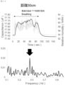
- FIG. 13 shows the results of measurements using the high-speed response product (2).
- a response was observed in the high-speed response product (2) even at a distance of 70 cm, and a very good agreement was obtained when comparing the results of the Fourier transform with the existing breathing sensor. This shows that respiration measurement is possible even if the sensor and mouth are separated by 70 cm.
- FIGS. 12 and 13 there are parts where no response is seen, but this is because the face moved during the measurement.
- FIG. 14 shows the measurement data and Fourier transform results when the high-speed response product (3) is installed on the steering wheel of a car. From FIG. 14, it can be seen that respiration can be measured by installing a sensor at the handle position.
- Example 6 Measurement in cone B area
- the humidity sensor is placed within the truncated cone area (colored area) in the cone B area as shown in FIG.
- the existing respiration sensor shown in Example 5 was used. The measurement data and the results of Fourier transformation are shown in FIG. From FIG. 16, it can be seen that very good agreement was obtained between the existing respiration sensor and the high-speed response product (2), indicating that respiration can be measured by installing a humidity sensor around the neck. It should be noted that during the measurement, there was a time when no response was observed, but this was due to the face moving.
- respiration can be measured by installing the sensor in this position, it is possible to constantly monitor respiration without being affected by vibrations by installing the sensor on a necklace, pet collar, or harness, for example.
- Example 7 Measurement in cone C region
- An example of respiration detection when a high-speed response product (1) and a low-speed response product are placed at the base of the neck (manubrium of the sternum) will be shown.
- the humidity sensor is placed within the truncated cone area (colored area) in the cone C area as shown in FIG.
- the measurement data and Fourier transform results are shown in FIG. From FIG. 18, while the slow response product cannot follow breathing, the response due to breathing can be confirmed in the fast response product (1).
- FIG. 19 shows the data measured with the engine OFF and the results of Fourier transformation. From FIG. 19, it can be seen that the nasal breathing component can be measured at the seat belt position. Further, FIG. 20 shows the data measured with the engine ON and the results of Fourier transformation. From FIG. 20, it can be seen that even if there is vibration from the car, respiration can be measured in the same way as when the engine is turned off.
- Example 8 (Measurement in cone A area and cone C area)
- Example 5 it was shown that mouth breathing components could be measured when a high-speed response product was installed on the handle.
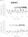
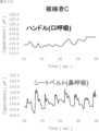
- FIGS. 21A to 21C show the measurement results of three subjects (the results shown so far are for subject A) at the steering wheel position and seat belt position.
- the humidity sensor is placed both within the truncated cone region (colored region) in the cone A region as shown in FIG. 11 and in the truncated cone region (colored region) in the cone C region as shown in FIG. Ru.
- the absolute values of the vertical and horizontal axes are combined. From FIGS.
- Subject A had a large response for both mouth breathing and nasal breathing
- subject B had a large mouth breathing response but a small nasal breathing response
- subject C has a small amount of mouth breathing but a large amount of nasal breathing.
- the nose acts as a filter to remove bacteria and viruses from the air, and humidified and warmed air is taken into the lungs through the nose, so it is generally said that breathing through the nose is a better way to breathe. ing. Therefore, by knowing whether you breathe through your mouth or through your nose, you can correct your breathing to improve your breathing.
- FIGS. 21A to 21C it can be confirmed that in both cases of mouth breathing and nose breathing, after a steep response, there is a slow recovery. This shows that the shape of breathing can be measured. This is because the humidity sensor's response and recovery are fast, allowing it to accurately measure humidity changes caused by breathing.
- Example 9 (combined with air conditioner)
- temperature and humidity sensors are installed around the air conditioner to control the air conditioner in cars.
- this sensor is located far away from the driver and passengers, and the temperature and humidity differs from the surroundings of the passengers and driver, which can often lead to uncomfortable conditions if the air conditioner is not working properly.
- a temperature and humidity sensor was installed at the seat belt position to measure the temperature and humidity around the driver.
- the temperature and humidity sensor (SHT31, manufactured by Sensirion, slow response product) installed in the BLE module was used for measurement. Changes in temperature and humidity were measured when the air conditioner was turned on at medium intensity. In addition, measurements were taken in this order when the air conditioner was directly hitting the body and when the air conditioner was not hitting the body with the same intensity. The results are shown in FIG. From FIG. 22, it can be seen that the temperature gradually decreases as the air from the air conditioner directly hits the body.
- a similar sensor on the seat belt of each seat, it can constantly measure the temperature and humidity around each seat, and when combined with HVAC, control the air conditioner when conditions become uncomfortable, making the inside of the car even more comfortable. can be improved.
- the high-speed response product shown in Example 3 may be used for the humidity display value.
- the output value of the high-speed response product used this time is capacitance, so by checking the relationship between capacitance and humidity (calibration curve) in advance, it is possible to convert capacitance to humidity. At this time, large slow fluctuations in the baseline correspond to changes in the humidity around the subject, and small, fast fluctuations correspond to changes in the humidity of the subject.
- porous moisture member of the present disclosure and the humidity sensor using the same can be used in various applications such as home appliances, industrial equipment, and vehicles.
- a porous moisture member for a humidity sensor A porous textured moisture member for a humidity sensor, The porous textured moisture member includes a resin matrix and an inorganic filler, The porous moisture member includes surface pores and internal pores, and the average pore diameter of the surface pores is 0.1 ⁇ m or more. Porous moisture material.
- a porous textured moisture member according to Item 1 wherein the density of the surface pores having a pore diameter of 0.1 ⁇ m or more is 1/100 ⁇ m 2 or more.
- the porous moisture material according to Item 1 or 2 wherein the surface pores having a pore diameter of 0.1 ⁇ m or more have a density of 50 or more/100 ⁇ m 2 .
- the porous moisture material according to any one of Items 1 to 4 wherein the density of pores having a cross-sectional diameter of 1 ⁇ m or more in the cross section of the porous moisture material is 10/100 ⁇ m 2 or more.
- the amount of the resin base material is 10% by weight or more and 90% by weight or less with respect to the porous textured moisture member, Item 10.
- the porous moisture material according to any one of Items 1 to 9, wherein the amount of the inorganic filler is 10% by weight or more and 90% by weight or less based on the porous moisture material.
- the resin base material is at least one selected from the group consisting of aromatic polyimide, aromatic polyamideimide, aromatic polyamide, aromatic polyether, polyethylene terephthalate, cellulose acetate butyrate, polymethyl methacrylate, and vinyl crotonate.
- the porous textured moisture member according to any one of Items 1 to 10, which is [Section 12] Item 12.
- Item 13 The porous textured moisture member according to any one of Items 1 to 12, wherein the inorganic filler includes a metal filler.
- the porous textured moisture member contains a surfactant, and the amount of the surfactant is 0.1% by weight or more and 25% by weight or less based on the porous textured moisture member. Porous textured moisture member as described in 2.
- Item 15 Item 15.
- the humidity sensor according to item 16 comprising a substrate, and the first electrode is provided on the substrate.
- Item 18 Item 18.
- a breathing detection system that detects breathing of a subject,
- the humidity sensor according to any one of items 16 to 18 is arranged within a spherical region,
- the sphere has a center at the subject's exhalation source and a radius of 150 cm or less.
- the humidity sensor is located within a cone A region;
- the cone A has an apex as the exhalation source and a rotation axis as a straight line extending from the exhalation source to the front direction of the subject, and an isosceles formed when the cone A is cut by a plane passing through the rotation axis.
- the respiratory detection system according to item 19 or 20, wherein the cone angle defined by the apex angle of the triangle is 40° or less, and the cone height defined by the straight line length from the center of the base to the apex is 100 cm or less. .
- the humidity sensor is located within a cone B region;
- the cone B has an apex as the exhalation source and a rotation axis as a straight line extending from the exhalation source in a direction of 30 degrees downward and 30 degrees to the right or left with the back direction as a reference, and the cone B has an apex as the exhalation source.
- the cone angle defined by the apex angle of the isosceles triangle formed when cut by a plane passing through the axis of rotation is 60° or less, and the cone height defined by the straight line length from the center of the base to the apex is 30 cm or less 21.
- the respiratory detection system according to item 19 or 20.
- the respiratory detection system according to item 21, wherein the exhaled air source is the subject's mouth, and the respiratory detection system detects a mouth breathing component, or the exhaled air source is the subject's mouth and/or nostril, and the respiratory detection system detects a mouth-breathing component.
- the humidity sensor is located within a cone C region;
- the cone C has an apex as the exhalation source and a rotation axis as a straight line extending downward from the exhalation source to the subject, and an isosceles formed when the cone C is cut by a plane passing through the rotation axis.
- Breathing detection according to any one of Items 19 to 27, wherein the control unit controls the surrounding environment of the subject using an air conditioning device based on the breathing detection result and other subject surrounding environment information such as the subject's ambient temperature if necessary. system.
- the control unit controls a device.
- the respiratory detection system according to clause 29, wherein the device is a motor vehicle.
- the humidity sensor is installed in a personal computer or computer-related equipment.
- the humidity sensor is placed on the neck.
- a straight-line distance between the humidity sensor and the exhalation source is 10 cm or more.
Landscapes
- Health & Medical Sciences (AREA)
- Life Sciences & Earth Sciences (AREA)
- Physics & Mathematics (AREA)
- Chemical & Material Sciences (AREA)
- Pathology (AREA)
- General Health & Medical Sciences (AREA)
- Engineering & Computer Science (AREA)
- Molecular Biology (AREA)
- Biomedical Technology (AREA)
- Biophysics (AREA)
- General Physics & Mathematics (AREA)
- Analytical Chemistry (AREA)
- Immunology (AREA)
- Biochemistry (AREA)
- Pulmonology (AREA)
- Surgery (AREA)
- Animal Behavior & Ethology (AREA)
- Heart & Thoracic Surgery (AREA)
- Public Health (AREA)
- Veterinary Medicine (AREA)
- Physiology (AREA)
- Medical Informatics (AREA)
- Electrochemistry (AREA)
- Chemical Kinetics & Catalysis (AREA)
- Oral & Maxillofacial Surgery (AREA)
- Dentistry (AREA)
- Power Engineering (AREA)
- Hematology (AREA)
- Urology & Nephrology (AREA)
- Food Science & Technology (AREA)
- Medicinal Chemistry (AREA)
- Investigating Or Analyzing Materials By The Use Of Fluid Adsorption Or Reactions (AREA)
- Investigating Or Analyzing Materials By The Use Of Electric Means (AREA)
Abstract
Description
(1)湿度センサー用の多孔質感湿部材であって、
前記多孔質感湿部材が樹脂母材及び無機フィラーを含み、
前記多孔質感湿部材が表面孔及び内部孔を含み、表面孔の平均孔径は0.1μm以上である、
多孔質感湿部材。
(2)湿度センサーであって、
第一電極と、
第二電極と、
前記第一電極と前記第二電極との間に設けられる上記(1)の多孔質感湿部材と
を備える、湿度センサー。
(3)被験者の呼吸を検知する呼吸検知システムであって;
上記(2)の湿度センサーが球体領域内に配置され;
前記球体は、中心が前記被験者の呼気源であり、半径が100cm以下である、呼吸検知システム。
本開示における多孔質感湿部材は、湿度センサーに好適に用いられるものである。本明細書において「部材」とは湿度センサーを構成する物のことであって、「材料」、「部品」、「部分」、「構成」等と言い換えることができる。
多孔質感湿部材の形状は使用される湿度センサーの構造にもよるが、通常、膜状又はシート状である。多孔質感湿部材の厚みは、0.5μm以上、1μm以上、2.5μm以上、5μm以上、又は10μm以上であってよく、好ましくは1μm以上である。多孔質感湿部材の厚みは、1000μm以下、500μm以下、100μm以下、50μm以下、10μm以下、又は5μm以下であってよく、好ましくは50μm以下である。上記範囲にあることが湿度センサーの感度又は応答性の観点から好適である。
本開示における多孔質感湿部材は多数の孔(空隙)を含んでいる。多孔質感湿部材の全体に孔が分布することが好ましく、多孔質感湿部材は表面孔のみならず、内部孔を含むことが好ましい。「表面孔」とは多孔質感湿部材の表面において多孔質感湿部材の外部に対して開いている孔のことをいう。「内部孔」は多孔質感湿部材の内部に存在し、多孔質感湿部材外部に対して開いていない孔のことをいう。内部孔は水平方向に扁平状であってよい。また、内部孔は隣接する孔と連通していてもよい(なお、表面孔に直接又は間接的に連通している孔であっても、多孔質感湿部材外部に対して直接的に開いていない限り、内部孔である。)。多孔質であることにより、感湿部材に多くの水分子が吸着し易くなり、湿度変化による感湿部材の物性の変化が大きくなり、感度が向上し得る。表面孔及び内部孔を含むことにより、湿度センサーの感度又は応答性が向上され得る。
表面孔の平均孔径は0.1μm以上、0.5μm以上、1μm以上、3μm以上、又は5μm以上であってよく、好ましくは1μm以上である。表面孔の平均孔径は50μm以下、25μm以下、10μm以下、5μm以下、2.5μm以下、1.2μm以下、0.6μm以下、又は0.2μm以下であってよい。表面孔の平均孔径は、基材への密着性の観点から多孔質感湿部材の厚みの1/2以下、1/3以下、1/4以下、又は1/5以下であってもよい。上記範囲にあることが湿度センサーの感度又は応答性の観点から好適である。孔径が大きいことにより水分子の出入りがし易くなるために応答性が向上すると共に、気孔表面で水分子が多層吸着できるために感度が向上し得る。表面孔の平均孔径は顕微鏡観察により求めることができる。顕微鏡で多孔質感湿部材の表面を観察し、観察される各表面孔の最長径を当該各表面孔の孔径とみなすことができる。視野内に存在する全ての表面孔の孔径を測定し、視野を移動して再度孔径を測定することを繰り返し、100個以上についての平均値を表面孔の平均孔径とする。
孔径0.1μm以上(当該孔径は、多孔質感湿部材の厚みの1/2以下、1/3以下、1/4以下、又は1/5以下、若しくは、10μm以下、5μm以下、2.5μm以下、又は1μm以下であってよく、特に10μm以下又は5μm以下である)の表面孔の密度は、1個/100μm2以上、5個/100μm2以上、10個/100μm2以上、50個/100μm2以上、100個/100μm2以上、250個/100μm2以上、500個/100μm2以上、又は750個/100μm2以上であってよく、好ましくは50個/100μm2以上、より好ましくは250個/100μm2以上である。孔径0.1μm以上(当該孔径は、多孔質感湿部材の厚みの1/2以下、1/3以下、1/4以下、又は1/5以下、若しくは10μm以下、5μm以下、2.5μm以下、又は1μm以下であってよく、特に10μm以下又は5μm以下である)の表面孔の密度は、2500個/100μm2以下、1000個/100μm2以下、500個/100μm2以下、250個/100μm2以下、又は100個/100μm2以下であってよい。上記範囲にあることが湿度センサーの感度又は応答性の観点から好適である。孔径が大きいことにより水分子の出入りがし易くなるために応答性が向上すると共に、孔表面で水分子が多層吸着できるために感度が向上し得る。表面孔の密度は、少なくとも視野100μm2以上の多孔質感湿部材の表面の顕微鏡画像から表面孔の密度を測定することにより求めることができる。
多孔質感湿部材の任意の断面において孔断面が存在することが好ましい。断面は厚み方向断面(鉛直方向断面)であってよい。存在する孔断面の断面径は、0.1μm以上、0.5μm以上、1μm以上、2μm以上、3μm以上、4μm以上、又は5μm以上であってよく、好ましくは1μm以上である。存在する孔断面の径は多孔質感湿部材の厚みの2/3以下、1/2以下、若しくは、50μm以下、25μm以下、10μm以下、7.5μm以下、又は5μm以下であってよく、好ましくは10μm以下である。上記範囲にあることが湿度センサーの感度又は応答性の観点から好適である。孔径が大きいことにより水分子の出入りがし易くなるために応答性が向上すると共に、気孔表面で水分子が多層吸着できるために感度が向上し得る。多孔質感湿部材の断面における孔断面の断面径は顕微鏡観察により求めることができる。顕微鏡で孔断面を観察し、観察される各孔断面の最長径を各孔断面の断面径とみなすことができる。断面観察の方法としては、エポキシ樹脂中に多孔質感湿部材を垂直に埋め込み、その埋め込み面を機械研磨した後に、SEM(走査型電子顕微鏡)で観察する方法や、FIB(集束イオンビーム)装置を用いて、多孔質感湿部材の断面が見えるように観察用試料を切り出し断面をSEM(走査型電子顕微鏡)で観察する方法等が挙げられる。
多孔質感湿部材の任意の断面において、断面径1μm以上(当該断面径は、多多孔質感湿部材の厚みの2/3以下、1/2以下、若しくは、10μm以下、5μm以下、2.5μm以下、又は1μm以下であってよく、特に10μm以下ある)の孔断面の密度は、10個/100μm2以上、20個/100μm2以上、30個/100μm2以上、40個/100μm2以上、50個/100μm2以上、60個/100μm2以上、又は70個/100μm2以上であってよく、50個/100μm2であることが好ましい。多孔質感湿部材の断面において、断面径1μm以上(当該断面径は、多多孔質感湿部材の厚みの2/3以下、1/2以下、若しくは、10μm以下、5μm以下、2.5μm以下、又は1μm以下であってよく、特に10μm以下ある)の孔断面の密度は、100個/100μm2以下、90個/100μm2以下、80個/100μm2以下、又は70個/100μm2以下であってよい。断面は厚み方向断面(鉛直方向断面)であってよい。上記範囲にあることが湿度センサーの感度又は応答性の観点から好適である。孔径が大きいことにより水分子の出入りがし易くなるために応答性が向上すると共に、気孔表面で水分子が多層吸着できるために感度が向上し得る。孔断面の密度は、少なくとも視野100μm2以上の多孔質感湿部材の断面から孔断面の密度を測定することにより求めることができる。
多孔質感湿部材の比表面積は0.1m2/g以上、0.5m2/g以上、1m2/g以上、2m2/g以上、3m2/g以上、5m2/g以上、又は7.5m2/g以上であってよい。多孔質感湿部材の比表面積は50m2/g以下、20m2/g以下、10m2/g以下、5m2/g以下、2m2/g以下、又は1.5m2/g以下であってよく、好ましくは2m2/g以下である。上記範囲にあることが湿度センサーの感度又は応答性の観点から好適である。比表面積はBET法により求めることができる。
多孔質感湿部材の気孔率は、5体積%以上、10体積%以上、20体積%以上、30体積%以上、40体積%以上、又は50体積%以上、60体積%以上、70体積%以上、80体積%以上、又は90体積%以上であってよく、好ましくは10体積%以上又は30体積%以上、より好ましくは60体積%以上である。多孔質感湿部材の気孔率は、99体積%以下、90体積%以下、80体積%以下、70体積%以下、60体積%以下、50体積%以下、40体積%以下、又は30体積%以下であってよく、好ましくは90体積%以下である。上記範囲にあることが湿度センサーの感度又は応答性の観点から好適である。気孔率が大きいことにより水分子の出入りがし易くなるために湿度センサーの応答性が向上すると共に、気孔表面で水分子が多層吸着できるために感度が向上し得る。気孔率は多孔質感湿部材の全体積に占める気孔の体積の割合で定義され、気孔率は光学的方法、水蒸発法、SEM画像観察、アルキメデス法等により求めることができる。
多孔質感湿部材の比誘電率は、1.2以上、1.4以上、1.6以上、1.8以上、2.0以上、2.2以上、2.4以上、2.7以上、3.0以上、又は3.3以上であってよく、高いほど好ましい。多孔質感湿部材の比誘電率は、100以下、80以下、60以下、40以下、20以下、10以下、7.5以下、又は5.0以下であってよい。上記範囲にあることが湿度センサーの感度又は応答性の観点から好適である。多孔質感湿部材の比誘電率が高くなることで水分子をより多く吸着することが出来、湿度変化による感湿部材の物性変化が大きくなることにより、感度が向上し得ると考えられる。
樹脂母材は、熱可塑性樹脂、熱硬化性樹脂、又はこれらの組み合わせであってよい。樹脂母材は、ホモポリマー、星形ブロック共重合体、グラフト共重合体、交互ブロック共重合体、ランダム共重合体のような共重合体、イオノマー、デンドリマー等であってよい。樹脂母材の例としては、ポリアミド、ポリイミド、ポリアミドイミド、ポリウレタン、ポリエーテル、ポリエーテルイミド、ポリエーテルケトン、ポリカーボネート、ポリエステル、ポリアクリル、ポリオレフィン、ポリビニルアルコール、ポリハロゲン化ビニル、ポリシロキサン、変性セルロース等が挙げられ、具体例としては、芳香族ポリイミド、芳香族ポリアミドイミド、芳香族ポリアミド、芳香族ポリエーテル、ポリエチレンテレフタラート、酢酸酪酸セルロース(CAB)、ポリメタクリル酸メチル(PMMA)、クロトン酸ビニル等が挙げられる。これらは単独で用いてもよいし、又は二以上を併用してもよい。
樹脂母材の量は、多孔質感湿部材に対して、10重量%以上、20重量%以上、30重量%以上、40重量%以上、50重量%以上、60重量%以上、又は70重量%以上であってよく、50重量%以上が好ましい。樹脂母材の量は、多孔質感湿部材に対して、99重量%以下、90重量%以下、80重量%以下、70重量%以下、60重量%以下、50重量%以下、40重量%以下、又は30重量%以下であってよい。
無機フィラーは、粒子状(球状、フレーク状、板状等)であってよい。無機フィラーの平均粒径は50nm以上、100nm以上、300nm以上、500nm以上、又は1000nm以上であってよい。無機フィラーの平均粒径は10000nm以下、5000nm以下、3000nm以下、1000nm以下、又は500nm以下であってよい。無機フィラーの平均粒径は顕微鏡観察により求めることができる。顕微鏡で無機フィラーを観察し、観察される無機フィラーの最長径を当該各無機フィラーの粒径とみなすことができる。視野内に存在する全ての無機フィラーの粒径を測定し、視野を移動して再度粒径を測定することを繰り返し、その平均値を無機フィラー粒子の平均粒径とする。
無機フィラーの量は、多孔質感湿部材に対して、1重量%以上、10重量%以上、20重量%以上、30重量%以上、40重量%以上、50重量%以上、60重量%以上、70重量%以上、80重量%以上、又は90重量%以上であってよく、湿度センサーの感度又は応答性の観点から、好ましくは30重量以上、より好ましくは50重量%以上、特に70重量%以上である。無機フィラーの量は、多孔質感湿部材に対して、99重量%以下、90重量%以下、80重量%以下、70重量%以下、60重量%以下、50重量%以下、40重量%以下、又は30重量%以下であってよい。
多孔質感湿部材は界面活性剤を含んでよい。界面活性剤を含むことにより、孔サイズや孔密度を調整することができる。界面活性剤の例としては、アニオン性、カチオン性、両性、及び非イオン性界面活性剤等が挙げられる。界面活性剤はフッ素系界面活性剤を含んでいてもよい。フッ素系界面活性剤を含むことにより、撥水性、撥油性、防汚性等を付与し、湿度センサーの良好な感度及び応答性をもたらし得る。また、疎水性イオン性界面活性剤を用いることで、より大きなサイズの孔を形成し得る。界面活性剤は単独で用いてもよいし、又は二以上を併用してもよい。
界面活性剤の量は、多孔質感湿部材に対して、0.1重量%以上、0.5重量%以上、1重量%以上、2重量%以上、3重量%以上、4重量%以上、又は5重量%以上であってよく、好ましくは1重量%以上である。界面活性剤の量は、多孔質感湿部材に対して、25重量%以下、20重量%以下、15重量%以下、10重量%以下、又は7.5重量%以下であってよい。
本開示における多孔質感湿部材はシランカップリング剤を含む又はシランカップリング剤により処理されていてよい。多孔質感湿部材がシランカップリング剤を含む又はシランカップリング剤により処理されことにより、樹脂母材と無機フィラーとの接着性が向上し、湿度センサーの良好な感度及び応答性をもたらし得る。
シランカップリング剤の量は、多孔質感湿部材に対して、0.1重量%以上、0.5重量%以上、1重量%以上、2重量%以上、3重量%以上、4重量%以上、又は5重量%以上であってよく、好ましくは1重量%以上である。シランカップリング剤の量は、多孔質感湿部材に対して、25重量%以下、20重量%以下、15重量%以下、10重量%以下、又は7.5重量%以下であってよい。
多孔質感湿部材は、その他成分が添加されていてもよい。その他成分の例としては、例えば、可塑剤、滑剤、着色剤(顔料、染料等)、紫外線吸収剤、酸化防止剤、老化防止剤、発泡剤、脱泡剤、補強剤、難燃剤、帯電防止剤、界面活性剤、表面処理剤、撥水剤、撥油剤、防汚剤等が挙げられる。これらは単独で用いてもよいし、又は二以上を併用してもよい。
その他成分の量は、本開示の効果を損なわない範囲で適宜選択できる。各その他成分の量は、多孔質感湿部材に対して、0.1重量%以上、0.3重量%以上、0.5重量%以上、0.7重量%以上、又は1重量%以上であってよい。その他成分の量は、多孔質感湿部材に対して、10重量%以下、7.5重量%以下、5重量%以下、3重量%以下、2重量%以下、又は1重量%以下であってよい。
多孔質感湿部材の製造方法は、分散液作製工程、及び塗布乾燥工程を含んでいてよい。分散液を作製工程においては、樹脂母材及び無機フィラー、必要によりその他成分を溶剤に分散して分散液を得る。塗布乾燥工程において、得られた分散液を基材(例えば基板、電極)に塗布し、さらに乾燥させることによって多孔質感湿部材を得ることができる。より積極的に発泡させたい時には分散液の成分として発泡剤を使用してもよい。
本開示はさらに、湿度センサーを提供する。本開示における湿度センサーは、
第一電極と、
第二電極と、
前記第一電極と前記第二電極との間に設けられる多孔質感湿部材とを備え得る。
本開示はさらに呼吸検知システムを提供する。呼吸検知システムとはセンサーを用いて被験者の呼吸を検知するシステムのことをいい、本開示における呼吸検知システムは湿度センサーを用いる。湿度センサーとしては、上述した本開示における湿度センサーを用いることが好ましい。
本開示における呼吸検知システムは上記で説明した多孔質感湿部材を用いる湿度センサーを用いることが好適である。
本開示における呼吸検知システムにおいて、好適に呼吸を検知するために湿度センサーが特定の領域に配置される。なお、湿度センサーが配置される領域とは、各湿度センサーの一部又は全部が配置される領域のことを意味してよく、例えば湿度センサーの重心が配置される領域のことを意味してよい。
湿度センサーが配置される領域は、球体領域内であってよい。ここで、球体は被験者の呼気源を中心とする。
湿度センサーが配置される領域は、円錐A領域であってよい。円錐Aは、頂点を被験者の呼気源として、回転軸を呼気源から被験者の正面方向へと延びる直線として有する。図11は呼吸検知システムにおける円錐A領域の模式図を示す。図11における円錐6領域内、好ましくは着色された円錐台領域内が、湿度センサーが配置される領域となり得る。ここで、円錐6の頂部に位置する着色されていない円錐の高さが湿度センサーと呼気源との最小直線距離となり得る。
湿度センサーが配置される領域は、円錐B領域であってよい。円錐Bは、頂点を前記呼気源として、回転軸を前記呼気源から背面方向を基準として下へ30°かつ右又は左へ30°の方向へと延びる直線として有する。図15は呼吸検知システムにおける湿度センサーの円錐B領域の模式図を示す。図15における円錐14又は14’領域内、好ましくは着色された円錐台領域内が、湿度センサーが配置される領域となり得る。ここで、円錐14又は14’の頂部に位置する着色されていない円錐の高さが湿度センサーと呼気源との最小直線距離となり得る。
湿度センサーが配置される領域は、円錐C領域であってよい。円錐Cは、頂点を前記呼気源として、回転軸を前記呼気源から前記被験者の下方向へと延びる直線として有する。図17は呼吸検知システムにおける湿度センサーの円錐C領域の模式図を示す。図17における円錐20領域内、好ましくは着色された円錐台領域内が、湿度センサーが配置される領域となり得る。ここで、円錐20の頂部に位置する着色されていない円錐の高さが湿度センサーと呼気源との最小直線距離となり得る。
上記において、湿度センサーの設置個所の例として、球体領域、円錐A領域、円錐B領域、及び円錐C領域を示したが、上記に設置個所は上記に限られない。また、球体領域、円錐A領域、円錐B領域、及び円錐C領域のうちの一又は複数に対して、一又は複数のセンサーを設置することも可能である。例えば、組合せとしては、円錐A領域と円錐B領域との組合せ、円錐A領域と円錐C領域との組合せ、円錐B領域と円錐C領域との組合せ、円錐A領域と円錐B領域と円錐C領域との組合せ等が挙げられる。例えば、円錐A領域は口呼吸の検出に適しており、円錐C領域は鼻呼吸の検出に適しているため、円錐A領域と円錐C領域とを組み合わせることで、口呼吸成分と鼻呼吸成分を別々に測定してもよい。このように、口呼吸成分と鼻呼吸成分を別々に測定することによってそれらを切り分けることが出来、それぞれの人が口呼吸・鼻呼吸どちらが主なのかを知ることが出来る。鼻は空気中の菌やウィルスを取り除くフィルターの役割があるうえ、鼻を通ることで加湿+加温された空気が肺に取り込まれるため、一般的に鼻呼吸の方が良い呼吸だと言われている。そのため、口呼吸・鼻呼吸どちらの呼吸をしているかを知ることで良い呼吸に矯正することも可能になる。
本開示における呼吸検知システムは呼吸検知結果に応答する制御部を備えてよい。
本開示における呼吸検知システムは、呼吸以外の第二のバイタルサインを含む第二振動データを測定するセンサーをさらに備えてもよい。
[式1]

作製した湿度センサーの評価は以下のとりである。
FDC2214EVM(Texas Instruments社製)の回路を用いて、湿度変化をした際の湿度センサーの容量変化を測定した。50%RHの湿度雰囲気下で安定させた湿度センサーに対し、バブラーで作製した湿潤空気を内径4mmの配管を用いて1SLMの流量で流す。この際の湿度センサーと配管の距離は10mmとした。既存の湿度センサーであるSHT31(Sensirion社製)も同時に測定し、このセンサーの湿度表示値の変化とFDC2214EVM回路の容量表示値の変化の比(fF/%RH)を湿度センサーの感度と定義した。なお、値は湿度変化により最も大きく変化した際の値を用いた。
センサーの応答性は応答時間及びリカバリー時間により評価する。応答時間はベースラインから湿潤空気に完全に応答した際の値の90%に達するまでにかかる時間(一般的にt90という)、リカバリー時間は湿潤空気に完全に応答した際の値から変化量の10%まで戻るのにかかる時間(一般的にt10という)である。
[実施例1]
感湿膜の母材としてポリアミドイミド(PAI)、無機フィラーとしてNiを用いた場合について説明する。PAIは、PAI原料がN-メチル-2-ピロリドン(NMP)及びテトラグライム(TEGM)に溶解しているワニスを用いた。Niフィラーは平均粒径が約300nmのものを用いた。これらの原料をNi量が0~50vol%になるように原料を秤量し、フーバーマーラーにてNiフィラーがワニス中で均一に分散するように混合した。このように作製したワニスを、カプトン基板上にスパッタ法により形成した200nm厚のNiCr下部電極上に、スクリーン印刷により塗布した後、空気中において150℃で5分間乾燥させることで多孔質ポリアミドイミド母材中にNiフィラーが分散した状態の感湿膜を形成した。その後スパッタ法により70nm厚の上部電極を形成した。
一例として、感湿膜形成時の溶剤量を変えた際の結果を用いて説明する。実施例1で用いたPAIワニスに対して50wt%溶剤を追加した。追加した溶剤はNMPとTEGM比がそれぞれ100:0、50:50、0:100になるようにした。また、無機フィラーとしてNiに代えてCaCu3Ti4O12(CCTO)を用い、PAIに対して50vol%添加した。これらの点を除き、実施例1と同様の方法でセンサー作製及び評価を行った。
一例として、界面活性剤を添加した際の結果を用いて説明する。界面活性剤としては親水性界面活性剤であるフタージェント251又は疎水性界面活性剤であるフタージェント710FM(共にネオス社製)を用いた。無機フィラーとしてNiに代えてCaCu3Ti4O12(CCTO)を用い、PAIに対して50vol%添加した。界面活性剤はCCTOに対して1wt%、3wt%、5wt%添加した。これらの点を除き、実施例1と同様の方法でセンサー作製及び評価を行った。
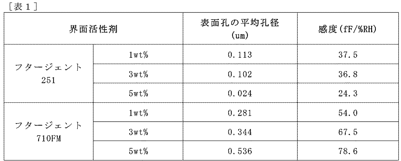
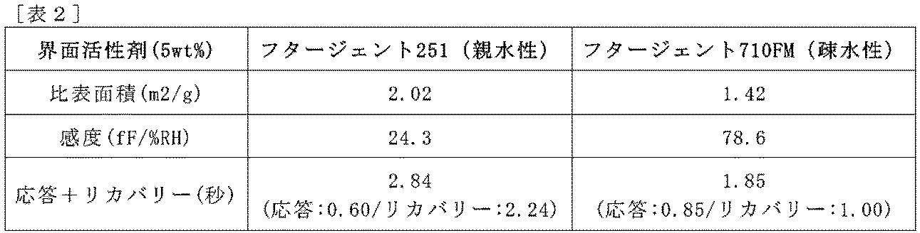
一例として、CCTO添加量を変更した場合について説明する。CCTOをPAIに対して0~50vol%添加した。この点を除き、実施例1と同様の方法でセンサー作製及び評価を行った。
[実施例5]
(用いた湿度センサー)
本開示における多孔質感湿部材を用いる湿度センサー三種類(以下、それぞれ、高速応答品(1)(2)(3)という。)と、市販品(SHT31、Sensirion製。以下、低速応答品という。)について、応答性を測定した。
高速応答品(1)(2)(3)でそれぞれ、応答速度は1.9秒、1.3秒、0.9秒、リカバリー速度は4.9秒、2.5秒、1.6秒であった。低速応答品の応答速度は5.5秒、リカバリー速度は16.1秒であった。
まず初めに、呼吸測定において振動の影響がないことを示すために以下の実験を行った。光チョッパーを用いて4Hzの周波数でバブラーを通した湿潤空気がセンサーに当たる状態で、センサー、光チョッパー、バブラー全てを振動させた。バブラーを通した湿潤空気が模擬的な呼吸に対応する。なおこの試験は、振動試験機を用いて国内輸送標準条件(JIS Z 0232規格、5~200Hz、Grms=0.59、ランダム振動、鉛直方向)にて行った。
振動なしにおける高速応答品(2)と低速応答品の比較結果(測定データ及びフーリエ変換結果)を図10に示す。図10より、低速応答品では4Hzの周波数変化に追従できていないことが分かる。これは応答速度及びリカバリー速度が遅いためと考えられる。
また図12や図13の測定データにおいて、応答が見られない部分があるが、これは測定時に顔が動いたためである。
(円錐B領域における測定)
高速応答品(2)を首の頸動脈付近に設置した場合について説明する。このとき湿度センサーは図15において示されるような円錐B領域における円錐台領域内(着色領域)に配置される。なお、呼吸が測定できているかを確認するために実施例5で示した既存の呼吸センサーを用いた。その測定データ及びフーリエ変換した結果を図16に示す。図16より、既存の呼吸センサーと高速応答品(2)で非常に良い一致が得られており、首元に湿度センサーを設置することで呼吸が測定できることが分かる。なお、測定中に一部応答が見られない時間があるが、これは顔が動いたためである。
(円錐C領域における測定)
高速応答品(1)及び低速応答品を首元(胸骨柄)に置いた場合における呼吸検知の例について示す。このとき湿度センサーは図17において示されるような円錐C領域における円錐台領域内(着色領域)に配置される。測定データ及びフーリエ変換した結果を図18に示す。図18より、低速応答品では呼吸に追従できていない一方で、高速応答品(1)では呼吸による応答が確認できる。
(円錐A領域及び円錐C領域における測定)
実施例5において、ハンドルに高速応答品を設置した際に口呼吸成分を測定できることを示した。そこで、3名の被験者(これまで示した結果は被検者Aによるもの)のハンドル位置及びシートベルト位置での測定結果を図21A~Cに示す。このとき湿度センサーは図11において示されるような円錐A領域における円錐台領域内(着色領域)と図17において示されるような円錐C領域における円錐台領域内(着色領域)との両方に配置される。なお3名の測定結果の比較のため、縦軸及び横軸の大きさの絶対値は合わせてある。図21A~Cより、3名の被験者によって応答が異なることが分かった。被験者Aは口呼吸、鼻呼吸共に応答が大きい一方で、被験者Bは口呼吸が大きいものの鼻呼吸は小さい。逆に被検者Cは口呼吸が小さいものの鼻呼吸は大きい。このように、口呼吸成分と鼻呼吸成分を別々に測定することによってそれらを切り分けることが出来、それぞれの人が口呼吸・鼻呼吸どちらが主なのかを知ることが出来ることがわかった。鼻は空気中の菌やウィルスを取り除くフィルターの役割があるうえ、鼻を通ることで加湿+加温された空気が肺に取り込まれるため、一般的に鼻呼吸の方が良い呼吸だと言われている。そのため、口呼吸・鼻呼吸どちらの呼吸をしているかを知ることで良い呼吸に矯正することも可能になる。
(エアコン併用)
現在車のエアコンを制御するために、エアコン周辺に温湿度センサーが設置されている。ところがこのセンサーはドライバーや乗員との距離が遠く、乗員やドライバー周辺の温湿度とは異なるため、エアコンが上手く機能していない場合には不快な状態になることが良くある。
4 呼気源
6 円錐A領域
8 円錐角度
10 円錐高さ
12 湿度センサーと呼気源との最小となり得る距離
14 円錐B領域(右側)
14’円錐B領域(左側)
16 背面方向を基準とする円錐Cの回転軸の角度(右へ60°)
18 背面方向を基準とする円錐Cの回転軸の角度(下へ30°)
x 正面方向
x’背面方向
20 円錐C領域
本開示の例示的態様は次のとおりである。
[項1]
湿度センサー用の多孔質感湿部材であって、
前記多孔質感湿部材が樹脂母材及び無機フィラーを含み、
前記多孔質感湿部材が表面孔及び内部孔を含み、表面孔の平均孔径は0.1μm以上である、
多孔質感湿部材。
[項2]
孔径0.1μm以上の前記表面孔の密度が1個/100μm2以上である、項1に記載の多孔質感湿部材。
[項3]
孔径0.1μm以上の前記表面孔の密度が50個以上/100μm2である、項1又は2に記載の多孔質感湿部材。
[項4]
前記多孔質感湿部材の断面において断面径1μm以上の孔断面が存在する、項1~3のいずれか一項に記載の多孔質感湿部材。
[項5]
前記多孔質感湿部材の断面において断面径1μm以上の孔断面の密度が10個/100μm2以上である、項1~4のいずれか一項に記載の多孔質感湿部材。
[項6]
前記多孔質感湿部材の比表面積が0.1m2/g以上10m2/g以下である、項1~5のいずれか一項に記載の多孔質感湿部材。
[項7]
前記多孔質感湿部材の比表面積が2m2/g以下である、項1~6のいずれか一項に記載の多孔質感湿部材。
[項8]
前記多孔質感湿部材の気孔率が10体積%以上90体積%以下である、項1~7のいずれか一項に記載の多孔質感湿部材。
[項9]
前記多孔質感湿部材の比誘電率が1.6以上である、項1~8のいずれか一項に記載の多孔質感湿部材。
[項10]
前記樹脂母材の量が、前記多孔質感湿部材に対して、10重量%以上90重量%以下であり、
前記無機フィラーの量が、前記多孔質感湿部材に対して、10重量%以上90重量%以下である、項1~9のいずれか一項に記載の多孔質感湿部材。
[項11]
前記樹脂母材が、芳香族ポリイミド、芳香族ポリアミドイミド、芳香族ポリアミド、芳香族ポリエーテル、ポリエチレンテレフタラート、酢酸酪酸セルロース、ポリメタクリル酸メチル、及びクロトン酸ビニルからなる群から選択される少なくとも一種である、項1~10のいずれか一項に記載の多孔質感湿部材。
[項12]
前記無機フィラーが、25℃及び1kHzにおける比誘電率が100以上の高誘電材料を含む、項1~11のいずれか一項に記載の多孔質感湿部材。
[項13]
前記無機フィラーが金属フィラーを含む、項1~12のいずれか一項に記載の多孔質感湿部材。
[項14]
前記多孔質感湿部材が界面活性剤を含み、前記界面活性剤の量が、前記多孔質感湿部材に対して、0.1重量%以上25重量%以下である、項1~13のいずれか一項に記載の多孔質感湿部材。
[項15]
静電容量変化型湿度センサー用である、項1~14のいずれか一項に記載の多孔質感湿部材。
[項16]
湿度センサーであって、
第一電極と、
第二電極と、
前記第一電極と前記第二電極との間に設けられる項1~15のいずれか一項に記載の多孔質感湿部材と
を備える、湿度センサー。
[項17]
基板を備え、前記基板上に前記第一電極が設けられている、項16に記載の湿度センサー。
[項18]
静電容量変化型である、項16又は17に記載の湿度センサー。
[項19]
被験者の呼吸を検知する呼吸検知システムであって、
項16~18のいずれか一項に記載の湿度センサーが球体領域内に配置され、
前記球体は、中心が前記被験者の呼気源であり、半径が150cm以下である、呼吸検知システム。
[項20]
前記湿度センサーが前記球体の背面上側の1/4球体領域を除く領域に配置される、項19に記載の呼吸検知システム。
[項21]
前記湿度センサーが円錐A領域内に配置され、
前記円錐Aが、頂点を前記呼気源として、回転軸を前記呼気源から前記被験者の正面方向へと延びる直線として有し、前記円錐Aを前記回転軸を通る平面で切断したときにできる二等辺三角形の頂角で定義される円錐角度が40°以下であり、底面中心から前記頂点までの直線長さで定義される円錐高さが100cm以下である、項19又は20に記載の呼吸検知システム。
[項22]
前記湿度センサーが円錐B領域内に配置され、
前記円錐Bは、頂点を前記呼気源として、回転軸を前記呼気源から背面方向を基準として下へ30°かつ右又は左へ30°の方向へと延びる直線として有し、前記円錐Bを前記回転軸を通る平面で切断したときにできる二等辺三角形の頂角で定義される円錐角度が60°以下であり、底面中心から前記頂点までの直線長さで定義される円錐高さが30cm以下である、項19又は20に記載の呼吸検知システム。
[項23]
前記呼気源が前記被験者の口であり、前記呼吸検知システムが口呼吸成分を検知する、項21に記載の呼吸検知システム、或いは
前記呼気源が前記被験者の口及び/又は鼻孔であり、前記呼吸検知システムが口呼吸成分及び/又は鼻呼吸成分を検知する、22に記載の呼吸検知システム。
[項24]
前記湿度センサーが円錐C領域内に配置され、
前記円錐Cが、頂点を前記呼気源として、回転軸を前記呼気源から前記被験者の下方向へと延びる直線として有し、前記円錐Cを前記回転軸を通る平面で切断したときにできる二等辺三角形の頂角で定義される円錐角度が60°以下であり、底面中心から前記頂点からまでの直線長さで定義される円錐高さが70cm以下である、項19又は20に記載の呼吸検知システム。
[項25]
前記呼気源が前記被験者の鼻孔であり、前記呼吸検知システムが鼻呼吸成分を検出する、項24に記載の呼吸検知システム。
[項26]
前記湿度センサーの応答時間とリカバリー時間の合計が5秒以下である、項19~25のいずれか一項に記載の呼吸検知システム。
[項27]
呼吸検知結果に応答する制御部を備える、項19~26のいずれか一項に記載の呼吸検知システム。
[項28]
前記制御部が前記呼吸検知結果及び必要により被験者周囲温度等のその他被験者周囲環境情報に基づき、空調機器により前記被験者の周囲環境を制御する、項19~27のいずれか一項に記載の呼吸検知システム。
[項29]
前記制御部が機器の制御を行う、項28に記載の呼吸検知システム。
[項30]
前記機器が自動車である、項29に記載の呼吸検知システム。
[項31]
呼吸以外の第二のバイタルサインを含む第二振動データを測定するセンサーをさらに備える、項19~30のいずれか一項に記載の呼吸検知システム。
[項32]
前記第二振動データから呼吸検知結果に基づく第一振動データを差し引くことにより、第二のバイタルサインを検知する、項31に記載の呼吸検知システム。
[項33]
前記湿度センサーが自動車のハンドルに設置される、項19~32のいずれか一項に記載の呼吸検知システム。
[項34]
前記湿度センサーがパソコン又はパソコン関連機器に設置される、項19~32のいずれか一項に記載の呼吸検知システム。
[項35]
前記湿度センサーが首に設置される、項19~32のいずれか一項に記載の呼吸検知システム。
[項36]
前記湿度センサーがペット(例えば犬や猫等)の首輪又はハーネスに設置される、項19~32のいずれか一項に記載の呼吸検知システム。
[項37]
前記湿度センサーが自動車のシートベルトに設置される、項19~32のいずれか一項に記載の呼吸検知システム。
[項38]
前記湿度センサーと前記呼気源との直線距離が5cm以上である、項19~37のいずれか一項に記載の呼吸検知システム。
[項39]
前記湿度センサーと前記呼気源との直線距離が10cm以上である、項19~38のいずれか一項に記載の呼吸検知システム。
Claims (27)
- 湿度センサー用の多孔質感湿部材であって、
前記多孔質感湿部材が樹脂母材及び無機フィラーを含み、
前記多孔質感湿部材が表面孔及び内部孔を含み、表面孔の平均孔径は0.1μm以上である、
多孔質感湿部材。 - 孔径0.1μm以上の前記表面孔の密度が1個/100μm2以上である、請求項1に記載の多孔質感湿部材。
- 孔径0.1μm以上の前記表面孔の密度が50個以上/100μm2である、請求項1又は2に記載の多孔質感湿部材。
- 前記多孔質感湿部材の断面において断面径1μm以上の孔断面が存在する、請求項1~3のいずれか一項に記載の多孔質感湿部材。
- 前記多孔質感湿部材の断面において断面径1μm以上の孔断面の密度が10個/100μm2以上である、請求項1~4のいずれか一項に記載の多孔質感湿部材。
- 前記多孔質感湿部材の比表面積が0.1m2/g以上10m2/g以下である、請求項1~5のいずれか一項に記載の多孔質感湿部材。
- 前記多孔質感湿部材の比表面積が2m2/g以下である、請求項1~6のいずれか一項に記載の多孔質感湿部材。
- 前記多孔質感湿部材の気孔率が10体積%以上90体積%以下である、請求項1~7のいずれか一項に記載の多孔質感湿部材。
- 前記多孔質感湿部材の比誘電率が1.6以上である、請求項1~8のいずれか一項に記載の多孔質感湿部材。
- 前記樹脂母材の量が、前記多孔質感湿部材に対して、10重量%以上90重量%以下であり、
前記無機フィラーの量が、前記多孔質感湿部材に対して、10重量%以上90重量%以下である、請求項1~9のいずれか一項に記載の多孔質感湿部材。 - 前記樹脂母材が、芳香族ポリイミド、芳香族ポリアミドイミド、芳香族ポリアミド、芳香族ポリエーテル、ポリエチレンテレフタラート、酢酸酪酸セルロース、ポリメタクリル酸メチル、及びクロトン酸ビニルからなる群から選択される少なくとも一種である、請求項1~10のいずれか一項に記載の多孔質感湿部材。
- 前記無機フィラーが、25℃及び1kHzにおける比誘電率が100以上の高誘電材料を含む、請求項1~11のいずれか一項に記載の多孔質感湿部材。
- 前記無機フィラーが金属フィラーを含む、請求項1~12のいずれか一項に記載の多孔質感湿部材。
- 前記多孔質感湿部材が界面活性剤を含み、前記界面活性剤の量が、前記多孔質感湿部材に対して、0.1重量%以上25重量%以下である、請求項1~13のいずれか一項に記載の多孔質感湿部材。
- 静電容量変化型湿度センサー用である、請求項1~14のいずれか一項に記載の多孔質感湿部材。
- 湿度センサーであって、
第一電極と、
第二電極と、
前記第一電極と前記第二電極との間に設けられる請求項1~15のいずれか一項に記載の多孔質感湿部材と
を備える、湿度センサー。 - 基板を備え、前記基板上に前記第一電極が設けられている、請求項16に記載の湿度センサー。
- 静電容量変化型である、請求項16又は17に記載の湿度センサー。
- 被験者の呼吸を検知する呼吸検知システムであって、
請求項16~18のいずれか一項に記載の湿度センサーが球体領域内に配置され、
前記球体は、中心が前記被験者の呼気源であり、半径が150cm以下である、呼吸検知システム。 - 前記湿度センサーが円錐A領域内に配置され、
前記円錐Aが、頂点を前記呼気源として、回転軸を前記呼気源から前記被験者の正面方向へと延びる直線として有し、前記円錐Aを前記回転軸を通る平面で切断したときにできる二等辺三角形の頂角で定義される円錐角度が40°以下であり、底面中心から前記頂点までの直線長さで定義される円錐高さが100cm以下であり、
前記呼気源が前記被験者の口である、請求項19に記載の呼吸検知システム。 - 前記湿度センサーが円錐B領域内に配置され、
前記円錐Bは、頂点を前記呼気源として、回転軸を前記呼気源から背面方向を基準として下へ30°かつ右又は左へ30°の方向へと延びる直線として有し、前記円錐Bを前記回転軸を通る平面で切断したときにできる二等辺三角形の頂角で定義される円錐角度が60°以下であり、底面中心から前記頂点までの直線長さで定義される円錐高さが30cm以下であり、
前記呼気源が前記被験者の口及び/又は鼻孔である、請求項19に記載の呼吸検知システム。 - 前記湿度センサーが円錐C領域内に配置され、
前記円錐Cが、頂点を前記呼気源として、回転軸を前記呼気源から前記被験者の下方向へと延びる直線として有し、前記円錐Cを前記回転軸を通る平面で切断したときにできる二等辺三角形の頂角で定義される円錐角度が60°以下であり、底面中心から前記頂点からまでの直線長さで定義される円錐高さが70cm以下であり、
前記呼気源が前記被験者の鼻孔である、請求項19に記載の呼吸検知システム。 - 前記湿度センサーの応答時間とリカバリー時間の合計が5秒以下である、請求項19~22のいずれか一項に記載の呼吸検知システム。
- 呼吸検知結果に応答する制御部を備え、
前記制御部が前記呼吸検知結果及び必要により被験者周囲温度等のその他被験者周囲環境情報に基づき、空調機器により前記被験者の周囲環境を制御する、請求項19~23のいずれか一項に記載の呼吸検知システム。 - 呼吸検知結果に応答する制御部を備え、
前記制御部が自動車の制御を行う、請求項19~24のいずれか一項に記載の呼吸検知システム。 - 呼吸以外の第二のバイタルサインを含む第二振動データを測定するセンサーをさらに備え、
前記第二振動データから呼吸検知結果に基づく第一振動データを差し引くことにより、第二のバイタルサインを検知する、請求項19~25のいずれか一項に記載の呼吸検知システム。 - 前記湿度センサーと前記呼気源との直線距離が5cm以上である、請求項19~26のいずれか一項に記載の呼吸検知システム。
Priority Applications (4)
| Application Number | Priority Date | Filing Date | Title |
|---|---|---|---|
| JP2023563198A JP7626249B2 (ja) | 2022-03-31 | 2023-03-10 | 多孔質感湿部材、湿度センサー、及び呼吸検知システム |
| DE112023000149.9T DE112023000149T5 (de) | 2022-03-31 | 2023-03-10 | Poröses feuchtigkeitsempfindliches element, feuchtigkeitssensor und atmungserfassungssystem |
| CN202380013605.1A CN117940766A (zh) | 2022-03-31 | 2023-03-10 | 多孔感湿构件、湿度传感器和呼吸检知系统 |
| US18/419,888 US20240183812A1 (en) | 2022-03-31 | 2024-01-23 | Porous moisture-sensitive member, humidity sensor, and respiration sensing system |
Applications Claiming Priority (2)
| Application Number | Priority Date | Filing Date | Title |
|---|---|---|---|
| JP2022-060776 | 2022-03-31 | ||
| JP2022060776 | 2022-03-31 |
Related Child Applications (1)
| Application Number | Title | Priority Date | Filing Date |
|---|---|---|---|
| US18/419,888 Continuation US20240183812A1 (en) | 2022-03-31 | 2024-01-23 | Porous moisture-sensitive member, humidity sensor, and respiration sensing system |
Publications (1)
| Publication Number | Publication Date |
|---|---|
| WO2023189409A1 true WO2023189409A1 (ja) | 2023-10-05 |
Family
ID=88200778
Family Applications (1)
| Application Number | Title | Priority Date | Filing Date |
|---|---|---|---|
| PCT/JP2023/009263 Ceased WO2023189409A1 (ja) | 2022-03-31 | 2023-03-10 | 多孔質感湿部材、湿度センサー、及び呼吸検知システム |
Country Status (5)
| Country | Link |
|---|---|
| US (1) | US20240183812A1 (ja) |
| JP (1) | JP7626249B2 (ja) |
| CN (1) | CN117940766A (ja) |
| DE (1) | DE112023000149T5 (ja) |
| WO (1) | WO2023189409A1 (ja) |
Citations (11)
| Publication number | Priority date | Publication date | Assignee | Title |
|---|---|---|---|---|
| JPS6430623A (en) * | 1987-07-24 | 1989-02-01 | Daiken Trade & Industry | Dehumidifying permeable structure |
| JPH02253822A (ja) * | 1989-03-27 | 1990-10-12 | Daiken Trade & Ind Co Ltd | 除湿装置 |
| JPH02272352A (ja) * | 1989-04-14 | 1990-11-07 | Nibetsukusu Kk | 感湿抵抗材料 |
| JPH0540104A (ja) * | 1991-08-08 | 1993-02-19 | Asahi Chem Ind Co Ltd | 感湿または結露センサの製造方法 |
| US20160299095A1 (en) * | 2015-04-09 | 2016-10-13 | Honeywell International Inc. | Relative humidity sensor and method |
| JP2018514436A (ja) * | 2015-04-14 | 2018-06-07 | オブチェストヴォ エス オグラニチェンノイ オトヴェツトヴェンノスチュ“オーテックス リミテッド” | 車両換気システム |
| JP2018196417A (ja) * | 2017-05-22 | 2018-12-13 | 国立大学法人神戸大学 | 生体状態計測装置および生体状態計測方法 |
| WO2019177002A1 (ja) * | 2018-03-14 | 2019-09-19 | パナソニックIpマネジメント株式会社 | 乗り物酔い推定システム、乗物、乗り物酔い推定方法、乗り物酔い推定プログラム |
| JP2020037664A (ja) * | 2018-09-06 | 2020-03-12 | 信越化学工業株式会社 | 多孔質シリコーンゴム球状粒子、多孔質シリコーン複合粒子、及びそれら粒子の製造方法 |
| WO2020166616A1 (ja) * | 2019-02-15 | 2020-08-20 | 国立研究開発法人産業技術総合研究所 | 感湿複合材及び湿度センサ |
| WO2021025229A1 (ko) * | 2019-08-05 | 2021-02-11 | 뉴턴1665 주식회사 | 신체상태측정 테이프 및 이를 이용하는 신체상태 모니터링 서비스 제공방법 |
Family Cites Families (3)
| Publication number | Priority date | Publication date | Assignee | Title |
|---|---|---|---|---|
| JPH1129151A (ja) | 1997-07-07 | 1999-02-02 | Sefutetsuku Kk | 土嚢用の袋 |
| JP4620959B2 (ja) | 2004-03-26 | 2011-01-26 | キヤノン株式会社 | 生体情報モニタ装置 |
| US20070208232A1 (en) | 2006-03-03 | 2007-09-06 | Physiowave Inc. | Physiologic monitoring initialization systems and methods |
-
2023
- 2023-03-10 DE DE112023000149.9T patent/DE112023000149T5/de active Pending
- 2023-03-10 CN CN202380013605.1A patent/CN117940766A/zh active Pending
- 2023-03-10 WO PCT/JP2023/009263 patent/WO2023189409A1/ja not_active Ceased
- 2023-03-10 JP JP2023563198A patent/JP7626249B2/ja active Active
-
2024
- 2024-01-23 US US18/419,888 patent/US20240183812A1/en active Pending
Patent Citations (11)
| Publication number | Priority date | Publication date | Assignee | Title |
|---|---|---|---|---|
| JPS6430623A (en) * | 1987-07-24 | 1989-02-01 | Daiken Trade & Industry | Dehumidifying permeable structure |
| JPH02253822A (ja) * | 1989-03-27 | 1990-10-12 | Daiken Trade & Ind Co Ltd | 除湿装置 |
| JPH02272352A (ja) * | 1989-04-14 | 1990-11-07 | Nibetsukusu Kk | 感湿抵抗材料 |
| JPH0540104A (ja) * | 1991-08-08 | 1993-02-19 | Asahi Chem Ind Co Ltd | 感湿または結露センサの製造方法 |
| US20160299095A1 (en) * | 2015-04-09 | 2016-10-13 | Honeywell International Inc. | Relative humidity sensor and method |
| JP2018514436A (ja) * | 2015-04-14 | 2018-06-07 | オブチェストヴォ エス オグラニチェンノイ オトヴェツトヴェンノスチュ“オーテックス リミテッド” | 車両換気システム |
| JP2018196417A (ja) * | 2017-05-22 | 2018-12-13 | 国立大学法人神戸大学 | 生体状態計測装置および生体状態計測方法 |
| WO2019177002A1 (ja) * | 2018-03-14 | 2019-09-19 | パナソニックIpマネジメント株式会社 | 乗り物酔い推定システム、乗物、乗り物酔い推定方法、乗り物酔い推定プログラム |
| JP2020037664A (ja) * | 2018-09-06 | 2020-03-12 | 信越化学工業株式会社 | 多孔質シリコーンゴム球状粒子、多孔質シリコーン複合粒子、及びそれら粒子の製造方法 |
| WO2020166616A1 (ja) * | 2019-02-15 | 2020-08-20 | 国立研究開発法人産業技術総合研究所 | 感湿複合材及び湿度センサ |
| WO2021025229A1 (ko) * | 2019-08-05 | 2021-02-11 | 뉴턴1665 주식회사 | 신체상태측정 테이프 및 이를 이용하는 신체상태 모니터링 서비스 제공방법 |
Also Published As
| Publication number | Publication date |
|---|---|
| DE112023000149T5 (de) | 2024-04-18 |
| US20240183812A1 (en) | 2024-06-06 |
| JP7626249B2 (ja) | 2025-02-04 |
| JPWO2023189409A1 (ja) | 2023-10-05 |
| CN117940766A (zh) | 2024-04-26 |
Similar Documents
| Publication | Publication Date | Title |
|---|---|---|
| Wang et al. | An integrated flexible self-powered wearable respiration sensor | |
| Jin et al. | A CNFs/MWCNTs aerogel film-based humidity sensor with directionally aligned porous structure for substantially enhancing both sensitivity and response speed | |
| Rabolli et al. | Influence of size, surface area and microporosity on the in vitro cytotoxic activity of amorphous silica nanoparticles in different cell types | |
| Feng et al. | TaS 2 nanosheet-based ultrafast response and flexible humidity sensor for multifunctional applications | |
| Xu et al. | Preparation of {200} crystal faced SnO2 nanorods with extremely high gas sensitivity at lower temperature: HY. Xu et al. | |
| EP2543694A1 (en) | Metal nanoparticle composite and process for production thereof | |
| Wu et al. | Synthesis of mesoporous NiO nanosheet and its application on mercury (II) sensor | |
| JP2007147592A (ja) | 化学蒸気センサー測定に影響を及ぼす環境変動を補償するためのトレーサー | |
| JP5849889B2 (ja) | 空調システム | |
| CN111704155B (zh) | 一种CeO2/g-C3N4杂化膜的湿度传感器及其制备方法和应用 | |
| JP7626249B2 (ja) | 多孔質感湿部材、湿度センサー、及び呼吸検知システム | |
| Sinha et al. | Wearable humidity sensor embroidered on a commercial face mask and its electrical properties | |
| Wang et al. | Superhydrophobic wearable sensor: fabrication, application, and perspective | |
| CN203561866U (zh) | 车内环境调节系统 | |
| Chen et al. | Voice-driven self-powered ethanol sensor for speech recognition and drunk driving detection | |
| Tang et al. | Respiration-based human-machine interface for aphasic patients with limited physical mobility | |
| Lan et al. | High-efficient and intelligent antibacterial face mask integrated with airflow-temperature dual-function sensors for respiratory monitoring and disease prevention | |
| Li et al. | Modeling analysis and experimental verification of IDE humidity sensor integrated with PZT: Ultra-fast response and recovery times | |
| CN110208334B (zh) | 针对呼出气的湿度传感器制备方法及其检测系统 | |
| Li et al. | α‐Co (OH) 2‐Based Quartz Crystal Microbalance Humidity Sensor for Real‐Time Monitoring of Respiration | |
| CN208238140U (zh) | 一种pmv指标的自适应船用空调控制器 | |
| JP2019089463A (ja) | 内装部品およびその製造方法 | |
| CN116749708A (zh) | 一种基于驾驶员状态的汽车空调智能控制系统 | |
| CN115923438A (zh) | 一种可检测车内环境的智能出风系统、方法、装置和终端 | |
| JPWO2023189409A5 (ja) |
Legal Events
| Date | Code | Title | Description |
|---|---|---|---|
| WWE | Wipo information: entry into national phase |
Ref document number: 2023563198 Country of ref document: JP |
|
| 121 | Ep: the epo has been informed by wipo that ep was designated in this application |
Ref document number: 23779433 Country of ref document: EP Kind code of ref document: A1 |
|
| WWE | Wipo information: entry into national phase |
Ref document number: 112023000149 Country of ref document: DE |
|
| WWE | Wipo information: entry into national phase |
Ref document number: 202380013605.1 Country of ref document: CN |
|
| 122 | Ep: pct application non-entry in european phase |
Ref document number: 23779433 Country of ref document: EP Kind code of ref document: A1 |