WO2023189376A1 - カテーテル - Google Patents
カテーテル Download PDFInfo
- Publication number
- WO2023189376A1 WO2023189376A1 PCT/JP2023/009132 JP2023009132W WO2023189376A1 WO 2023189376 A1 WO2023189376 A1 WO 2023189376A1 JP 2023009132 W JP2023009132 W JP 2023009132W WO 2023189376 A1 WO2023189376 A1 WO 2023189376A1
- Authority
- WO
- WIPO (PCT)
- Prior art keywords
- bag
- outer tube
- flow path
- catheter
- tube
- Prior art date
- Legal status (The legal status is an assumption and is not a legal conclusion. Google has not performed a legal analysis and makes no representation as to the accuracy of the status listed.)
- Ceased
Links
Images







Classifications
-
- A—HUMAN NECESSITIES
- A61—MEDICAL OR VETERINARY SCIENCE; HYGIENE
- A61M—DEVICES FOR INTRODUCING MEDIA INTO, OR ONTO, THE BODY; DEVICES FOR TRANSDUCING BODY MEDIA OR FOR TAKING MEDIA FROM THE BODY; DEVICES FOR PRODUCING OR ENDING SLEEP OR STUPOR
- A61M25/00—Catheters; Hollow probes
-
- A—HUMAN NECESSITIES
- A61—MEDICAL OR VETERINARY SCIENCE; HYGIENE
- A61M—DEVICES FOR INTRODUCING MEDIA INTO, OR ONTO, THE BODY; DEVICES FOR TRANSDUCING BODY MEDIA OR FOR TAKING MEDIA FROM THE BODY; DEVICES FOR PRODUCING OR ENDING SLEEP OR STUPOR
- A61M25/00—Catheters; Hollow probes
- A61M25/0021—Catheters; Hollow probes characterised by the form of the tubing
-
- A—HUMAN NECESSITIES
- A61—MEDICAL OR VETERINARY SCIENCE; HYGIENE
- A61M—DEVICES FOR INTRODUCING MEDIA INTO, OR ONTO, THE BODY; DEVICES FOR TRANSDUCING BODY MEDIA OR FOR TAKING MEDIA FROM THE BODY; DEVICES FOR PRODUCING OR ENDING SLEEP OR STUPOR
- A61M25/00—Catheters; Hollow probes
- A61M25/01—Introducing, guiding, advancing, emplacing or holding catheters
- A61M25/06—Body-piercing guide needles or the like
-
- A—HUMAN NECESSITIES
- A61—MEDICAL OR VETERINARY SCIENCE; HYGIENE
- A61M—DEVICES FOR INTRODUCING MEDIA INTO, OR ONTO, THE BODY; DEVICES FOR TRANSDUCING BODY MEDIA OR FOR TAKING MEDIA FROM THE BODY; DEVICES FOR PRODUCING OR ENDING SLEEP OR STUPOR
- A61M25/00—Catheters; Hollow probes
- A61M25/10—Balloon catheters
-
- A—HUMAN NECESSITIES
- A61—MEDICAL OR VETERINARY SCIENCE; HYGIENE
- A61M—DEVICES FOR INTRODUCING MEDIA INTO, OR ONTO, THE BODY; DEVICES FOR TRANSDUCING BODY MEDIA OR FOR TAKING MEDIA FROM THE BODY; DEVICES FOR PRODUCING OR ENDING SLEEP OR STUPOR
- A61M29/00—Dilators with or without means for introducing media, e.g. remedies
Definitions
- the present invention relates to a catheter.
- resin tubes are used to transport medical devices such as balloons and stents to the treatment area that is the target of treatment.
- the medical device is inserted into a body cavity such as a blood vessel while being placed in the inner lumen of a resin tube, and is transported to a treatment area.
- the resin tube used at this time has a simple cylindrical shape, there are problems in that the distal end portion hits the wall of the body cavity, damaging the wall of the body cavity and impairing passageability.
- Patent Document 1 describes a catheter that can make it difficult to damage the wall of a body cavity.
- the catheter has an elongated resilient tubular member having at least one lumen. Attached to the distal end of the catheter is a soft, deformable tip that expands in outer diameter and increases the contact area when pressed against a relatively stationary surface. It is stated that this makes it possible to reduce the pressure or force per unit area applied to the tissue.
- Patent Document 2 describes a medical technology instrument with good operability.
- the device includes an elongate, tubular, deformable inner body, an elongate, outer envelope that circumferentially surrounds the deformable body, at least partially, and which allows the device to be moved from a deformable state to a rigid state, and vice versa. and a device for migrating.
- the inner body is formed in the form of a double tube having an inner tube constituting an inner wall and an outer tube concentrically surrounding the inner tube constituting an outer wall.
- the device for transitioning the device from a variable state to a rigid state and vice versa applies pressure to the envelope by increasing pressure within the annular gap and radially expanding the outer tube.
- the description states that it causes the user to become rigid and is easy to operate. It is also described that although the outer diameter of the double tube included in the inner body increases, the size of the internal space included in the inner body remains fixed.
- the catheter described in Patent Document 1 prevents damage to the body cavity by increasing the outer diameter of the tip part, and the configuration of the catheter described in Patent Document 1 prevents damage to the body cavity.
- the outer diameter is expanded by applying pressure to create a rigid state and improve operability. They tend to get caught on the walls of body cavities, and there is still room for improvement in terms of improved passage through body cavities.
- the present invention has been made in view of the above-mentioned circumstances, and its purpose is to make it easier to prevent damage to the wall of the body cavity during transportation to the treatment section, and to make it easier to improve passage within the body cavity.
- Our goal is to provide catheters that can.
- an outer tube having a distal end and a proximal end and a longitudinally extending lumen; a bag-like body provided at a distal portion of the outer tube, the bag-like body being formed in an annular shape and having a portion having a smaller outer diameter than the outer tube; A flow path through which fluid can be injected to the bag-like body, The minimum inner diameter of the bag-like body when the bag-like body is pressurized at a predetermined pressure by the injection of fluid into the flow path is A catheter that is larger than the minimum inner diameter of the bag-like body in a state where no pressure is applied by injection.
- the catheter is transported to the treatment area without injecting fluid into the flow path.
- the outer diameter of the part of the bag-like body that is smaller than the outer tube remains small, making it less likely to get caught on the wall of the body cavity and being transported to the treatment area. This makes it easier to prevent the catheter from damaging the wall of the body cavity when using the catheter. Furthermore, the passage through the body cavity can be easily improved.
- the bag-like body is pressurized, and the minimum inner diameter of the bag-like body becomes larger than before pressurization. This makes it easier to protrude the medical device from the expanded diameter portion even when medical devices such as balloons, stents, baskets, needles, etc. are placed in the inner lumen of the outer tube and transported to the treatment area. I can do it.
- the catheter of the present invention preferably has the following [2] to [18].
- [2] In a state where pressurization is not performed by injecting fluid into the flow path, the bag-like body has an inner surface portion facing inward and an outer surface portion facing outside.[ 1].
- [3] When the bag-like body changes from a state in which it is not pressurized by injecting fluid into the flow path to a state in which it is pressurized at a predetermined pressure by injecting fluid into the flow path.
- the catheter according to [2] wherein the elongation rate of the length from the distal end to the proximal end of the inner surface portion is greater than the elongation rate of the length from the distal end to the proximal end of the outer surface portion.
- the angle formed by the inner surface portion and the outer surface portion in a state where no pressure is applied by injecting fluid into the flow path is an acute angle [2] or [3] The catheter described in ].
- the angle formed by the inner surface portion and the outer surface portion is an acute angle when the fluid is injected into the flow path and pressurized at a predetermined pressure.
- the catheter according to any one of [2] to [4].
- [6] When the bag-like body changes from a state in which it is not pressurized by injecting fluid into the flow path to a state in which it is pressurized at a predetermined pressure by injecting fluid into the flow path.
- the catheter according to item 1 has a wall forming a lumen, The catheter according to any one of [1] to [6], wherein the flow path is formed within the wall of the outer tube.
- the outer tube has an outer cylinder and an inner cylinder disposed in the inner cavity of the outer cylinder, The catheter according to [7], wherein the flow path is a space defined by an inner surface of the outer tube and an outer surface of the inner tube.
- the bag-like body is provided distally from the distal end of the outer tube, and has a tapered portion whose outer diameter decreases toward the distal side [1]
- the bag-shaped body and the outer tube have an X-ray opaque marker on at least one of the regions from the distal end to the proximal side of 10 cm. Catheter according to any one of the items.
- the outer tube has a reduced diameter region in the proximal portion thereof, the radial length of which becomes smaller toward the proximal side when observed from a direction perpendicular to the longitudinal direction.[1 ] to [12].
- the catheter according to any one of [12]. [14] further comprising a first cylindrical member having a maximum outer diameter smaller than the maximum outer diameter of the outer tube and having an inner cavity extending in the longitudinal direction; a distal portion of the first cylindrical member is fixed to a proximal portion of the reduced diameter region;
- the catheter according to [13] wherein the lumen of the first cylindrical member and the flow path are in communication.
- the expansion member is a balloon or a stent having a coating layer formed on its outer surface.
- the coating layer contains a physiologically active drug.
- the catheter of the present invention allows medical devices such as balloons, stents, baskets, needles, etc. to be easily protruded even when conveying them to the treatment area, and prevents damage to the wall of the body cavity when conveying them to the treatment area. It can be easily prevented and the passage inside the body cavity can be easily improved.
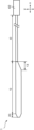
- FIG. 1 is a side view showing an example of a catheter according to an embodiment of the present invention.
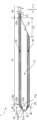
- 2 is an enlarged cross-sectional view of the distal side of the catheter shown in FIG. 1.
- FIG. 3 shows an end view of the catheter shown in FIG. 2 cut along line III-III.
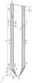
- FIG. 2 is an enlarged cross-sectional view of the distal side of the catheter shown in FIG. 1, showing a state where no pressure is applied by injecting fluid into the flow path.
- FIG. 5 shows an end view of the catheter shown in FIG. 4 cut along line VV.
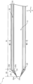
- 5 is a cross-sectional view of the catheter shown in FIG. 4 when it is pressurized at a predetermined pressure by injecting fluid into the flow path. 5 is a sectional view showing a modification of the catheter shown in FIG. 4.
- FIG. 4 shows an end view of the catheter shown in FIG. 4.
- FIG. 8 shows an end view of the catheter shown in FIG. 7 taken along line VIII-VIII.
- 5 is a sectional view showing another modification of the catheter shown in FIG. 4.
- FIG. 10 shows a cut end view of the catheter shown in FIG. 9 taken along line XX.
- 5 is a cross-sectional view (partially a side view) showing another modification of the catheter shown in FIG. 4.
- FIG. 12 shows an end view of the catheter shown in FIG. 11 cut along line XII-XII. 12 is a cross-sectional view (partial side view) of the catheter shown in FIG. 11 in a state where it is pressurized at a predetermined pressure by injecting fluid into the channel.
- One embodiment of the catheter of the present invention includes an outer tube having a distal end and a proximal end and having a longitudinally extending lumen; a bag-like body which is formed in an annular shape and has a portion having a smaller outer diameter than the outer tube; a flow path through which fluid can be injected to the bag-like body; The minimum inner diameter of the bag when the bag is pressurized at a predetermined pressure by injecting fluid into the flow path is The gist is that the diameter is larger than the minimum inner diameter of the bag-like body in a state where no pressure is applied by injection.
- the longitudinal direction of the outer tube 10 is indicated by x
- the radial direction is indicated by y.
- the radial direction y is a direction perpendicular to the longitudinal direction x, but only one direction perpendicular to the longitudinal direction x is shown here.
- the proximal side refers to the user's proximal side with respect to the extending direction of the outer tube 10
- the distal side refers to the side opposite to the proximal side, that is, the side to be treated.
- the distal part of each member refers to the distal half of each member
- the proximal part of each member refers to the proximal half of each member.
- FIG. 1 represents a side view showing an example of a catheter according to an embodiment of the present invention.
- FIG. 2 shows an enlarged cross-sectional view of the distal side of the catheter 1 shown in FIG.
- FIG. 3 shows an end view of the catheter 1 cut along the line III--III shown in FIG. Note that FIGS. 1 to 3 represent a state in which pressurization by injection of fluid into the flow path is not performed.
- the catheter 1 has an outer tube 10.
- Outer tube 10 has a distal end 10a and a proximal end 10b, and has a lumen 11 extending in the longitudinal direction x.
- a bag-like body 20 is provided at the distal portion of the outer tube 10.
- the bag-like body 20 is a bag-like member formed in an annular shape, and has a portion whose outer diameter is smaller than that of the outer tube 10.
- the bag-like body 20 has an annular shape when viewed from the longitudinal direction x.
- the catheter 1 includes a flow path 30.
- the flow path 30 is a space through which fluid can pass when injecting the fluid to the bag-shaped body 20.
- FIG. 4 is an enlarged cross-sectional view of the distal side of the catheter 1 shown in FIG. 1, showing a state in which no pressurization is performed by injecting fluid into the flow path 30.
- FIG. 5 shows an end view of the catheter shown in FIG. 4 cut along line VV.
- FIG. 6 shows a cross-sectional view of the catheter 1 when the fluid is injected into the flow path 30 of the catheter 1 shown in FIG. 4 and the catheter 1 is pressurized at a predetermined pressure.
- the catheter 1 has a minimum inner diameter of the bag-like body 20 when the bag-like body 20 is pressurized at a predetermined pressure by injecting fluid into the flow path 30.
- the bag-like body 20 is configured to be larger than the minimum inner diameter of the bag-like body 20 in a state where no pressure is applied by injecting fluid into the flow path 30.
- the catheter 1 is transported to the treatment section without injecting fluid into the flow path 30.
- the catheter 1 is transported to the treatment section in the state shown in FIG.
- the outer diameter of the part of the bag-like body 20 that is smaller than the outer tube 10 remains small, making it less likely to get caught on the wall of the body cavity, and reaching the treatment area. It is possible to easily prevent the catheter 1 from damaging the wall of the body cavity during transportation. Furthermore, the passage through the body cavity can be easily improved.
- the bag-like body 20 is pressurized, and the minimum inner diameter of the bag-like body 20 becomes larger than before pressurization.
- the catheter 1 is in the state shown in FIG.
- a medical device such as a balloon, stent, basket, needle, etc.
- the medical device can easily protrude from the expanded diameter portion. can do.
- the outer tube 10 Since the outer tube 10 is inserted into the body, it preferably has flexibility. This allows the outer tube 10 to be deformed along the shape of the body cavity. Further, in order to maintain the shape, it is preferable that the outer tube 10 has elasticity.
- the outer tube 10 is a hollow body formed by arranging one or more wire rods in a predetermined pattern; a resin coated on at least one of the inner surface or outer surface of the hollow body; a resin tube; or Examples include combinations of these, for example, those connected in the longitudinal axis direction.
- Examples of the hollow body in which the wires are arranged in a predetermined pattern include a cylindrical body having a network structure by simply crossing or weaving the wires, and a coil in which the wires are wound.
- the wire may be one or more single wires, or one or more twisted wires.
- the resin tube can be manufactured, for example, by extrusion molding.
- the outer tube 10 is a resin tube, the outer tube 10 can be composed of a single layer or multiple layers. A portion of the outer tube 10 in the longitudinal direction x or the circumferential direction may be composed of a single layer, and the other portion may be composed of multiple layers.
- the outer tube 10 is made of, for example, polyolefin resin (for example, polyethylene or polypropylene), polyamide resin (for example, nylon), polyester resin (for example, PET), aromatic polyetherketone resin (for example, PEEK), polyether polyamide resin, It can be made of synthetic resin such as polyurethane resin, polyimide resin, fluororesin (for example, PTFE, PFA, ETFE), or metal such as stainless steel, carbon steel, nickel-titanium alloy. These may be used alone or in combination of two or more.
- polyolefin resin for example, polyethylene or polypropylene
- polyamide resin for example, nylon
- polyester resin for example, PET
- aromatic polyetherketone resin for example, PEEK
- polyether polyamide resin It can be made of synthetic resin such as polyurethane resin, polyimide resin, fluororesin (for example, PTFE, PFA, ETFE), or metal such as stainless steel, carbon steel, nickel-titanium alloy. These may be used alone or in
- the outer surface of the outer tube 10 is preferably coated with a hydrophilic polymer. This allows the outer tube 10 to be easily inserted into the body cavity.
- a hydrophilic polymer include poly2-hydroxyethyl methacrylate, polyacrylamide, polyvinylpyrrolidone, maleic anhydride copolymers such as methyl vinyl ether maleic anhydride copolymer, and polyethylene glycol.
- the inner surface of the outer tube 10 preferably has a portion made of fluororesin or polyolefin resin. Only a portion of the inner surface of the outer tube 10 may be made of a fluororesin or a polyolefin resin, or the entire inner surface of the outer tube 10 may be made of a fluororesin or a polyolefin resin. This allows the outer tube 10 to easily slide on the members disposed in the inner lumen 11 of the outer tube 10, thereby making it easier to improve the operability of the catheter 1.
- the outer diameter of the outer tube 10 can be, for example, 1.0 mm or more, 1.1 mm or more, 1.2 mm or more, etc. Further, the outer diameter of the outer tube 10 can be, for example, 5.0 mm or less, 4.0 mm or less, 3.0 mm or less, but preferably 2.0 mm or less.
- the inner diameter of the outer tube 10 can be, for example, 4.0 mm or less, 3.8 mm or less, 3.5 mm or less, etc.
- the inner diameter of the outer tube 10 can be, for example, 0.4 mm or more, 0.5 mm or more, 0.6 mm or more, but preferably 0.8 mm or more, and preferably 1.2 mm or more. More preferred. It is also preferable that the inner diameter of the outer tube 10 is large enough to allow an inner tube 50 having an expansion member 60 (described later) to pass therethrough.
- the outer tube 10 has a distal end 10a and a proximal end 10b, a distal opening 11a and a proximal opening that communicate the inner lumen 11 of the outer tube 10 with the outside of the outer tube 10.
- the structure may include a portion 11b.
- the outer tube 10 has a length in the radial direction y when observed from a direction perpendicular to the longitudinal direction x of the outer tube 10 at the proximal portion of the outer tube 10. It is possible to have a configuration having a diameter-reduced region 13 that becomes smaller toward the center.
- a proximal opening 11b in the reduced diameter region 13 that communicates the inner lumen 11 of the outer tube 10 with the outside of the outer tube 10
- a proximal portion that communicates the inner lumen 11 of the outer tube 10 with the outside of the outer tube 10 is located at a portion that is inclined so that the length in the radial direction y decreases toward the proximal side when observed from a direction perpendicular to . It is more preferable to adopt a configuration in which a position-side opening 11b is formed.
- medical tools such as a guide wire, a balloon, a stent, a basket, a needle, etc., which will be described later, can be inserted into or removed from the outer tube 10 through the proximal opening 11b.
- the catheter 1 has a lumen 41 having a maximum outer diameter smaller than the maximum outer diameter of the outer tube 10 and extending in the longitudinal direction x of the outer tube 10. It further includes a first cylindrical member 40, the distal part of which is fixed to the proximal part of the reduced diameter region 13, and the lumen 41 of the first cylindrical member 40 and the fluid flow. It is possible to have a configuration in which the duct 30 is in communication with the duct 30.
- the first cylindrical member 40 is a cylindrical member having an inner cavity 41 and whose maximum outer diameter is smaller than the maximum outer diameter of the outer tube 10.
- the minimum outer diameter of the first cylindrical member 40 may also be smaller than the minimum outer diameter of the outer tube 10.
- the outer diameter of the first cylindrical member 40 can be, for example, 0.60 mm or more, 0.65 mm or more, 0.70 mm or more, etc. Further, the outer diameter of the first cylindrical member 40 can be, for example, 3.00 mm or less, 2.95 mm or less, 2.90 mm or less, but preferably 1.00 mm or less.
- the inner diameter of the first cylindrical member 40 can be, for example, 2.50 mm or less, 2.45 mm or less, 2.35 mm or less, etc. Further, the inner diameter of the first cylindrical member 40 can be, for example, 0.30 mm or more, 0.35 mm or more, 0.40 mm or more, but preferably 0.50 mm or more.
- the length from the distal end of the first cylindrical member 40 to the proximal end of the first cylindrical member 40 can be, for example, 100 mm or more, 150 mm or more, 200 mm or more, etc. Further, the length from the distal end of the first cylindrical member 40 to the proximal end of the first cylindrical member 40 can be, for example, 2400 mm or less, 2350 mm or less, 2300 mm or less, or the like.
- the length from the distal end 10a of the outer tube 10 to the proximal end 10b of the outer tube 10 is, for example, 30 mm or more, 35 mm or more, or 40 mm. It is possible to do more than that. Further, the length from the distal end 10a of the outer tube 10 to the proximal end 10b of the outer tube 10 can be, for example, 700 mm or less, 650 mm or less, 600 mm or less, etc.
- the same synthetic resin, metal, etc. as the outer tube 10 can be used as the material constituting the first cylindrical member 40.
- the materials constituting the first cylindrical member 40 and the outer tube 10 may be the same or different materials.
- a lubricating coating layer containing PTFE, PFA, etc. is formed on the outer surface of the first cylindrical member 40. This allows the first cylindrical member 40 to be easily inserted into the body cavity.
- a position indicating marker may be attached to the first cylindrical member 40 to indicate the length of the inserted portion when it is inserted into the body cavity from the distal end of the catheter 1.
- the position display marker may be formed, for example, by inserting and welding the first cylindrical member 40 into the inner cavity of the marker tube, or may be formed by inserting the first cylindrical member 40 into the inner cavity of the marker tube and welding it. It may be formed by peeling off a part of the coating layer.
- the position display marker can be provided, for example, at a position of 600 mm, 900 mm, 1200 mm, etc. from the distal end of the catheter 1.
- the distal part of the first cylindrical member 40 and the proximal part of the reduced diameter region 13 are fixed so that the lumen 41 of the first cylindrical member 40 and the flow path 30 communicate with each other, More preferably, the distal end of the first cylindrical member 40 and the proximal end of the reduced diameter region 13 are fixed. Note that it is preferable that the inner cavity 41 of the first cylindrical member 40 not communicate with the inner cavity 11 of the outer tube 10 .
- the catheter 1 preferably further includes a hub 42 at the proximal end of the first cylindrical member 40.
- the hub 42 has a port therein that communicates with the inner cavity 41 of the first cylindrical member 40, and is a member used when injecting fluid into the inner cavity 41 of the first cylindrical member 40.
- the proximal end of the outer tube 10 may be directly connected to the hub 42.
- the hub 42 may have a port therein that communicates with the flow path 30 to inject fluid into the flow path 30.
- the same synthetic resin, metal, etc. as the outer tube 10 can be used as the material constituting the bag-like body 20 as the material constituting the bag-like body 20.
- the proximal part of the pouch 20 may be connected to the distal part of the outer tube 10, and the proximal end of the pouch 20 may be connected to the distal end of the outer tube 10. 10a.
- a portion of the bag-like body 20 having an outer diameter smaller than that of the outer tube 10 is located at a distal portion of the bag-like body 20; More preferably, it is located at the distal end of the bag-like body 20.
- the bag-like body 20 is formed in an annular shape, for example, as shown in FIGS. 1 to 3, the bag-like body 20 may have a hollow truncated cone shape. As shown in FIGS. 2 and 3, the bag-like body 20 is formed in an annular shape and may have a lumen 25 that communicates with the outside of the bag-like body 20. As shown in FIG. 2, it is preferable that the inner cavity 25 of the bag-like body 20 and the inner cavity 11 of the outer tube 10 communicate with each other.
- the length of the bag-like body 20 in the longitudinal direction x in a state where no pressure is applied by injecting fluid into the flow path 30 can be, for example, 1 mm or more, 3 mm or more, 5 mm or more, etc.
- the length of the bag-like body 20 in the longitudinal direction x in a state where no pressure is applied by injecting fluid into the flow path 30 can be, for example, 20 mm or less, 18 mm or less, 15 mm or less, or the like.
- the length of the bag-like body 20 in the longitudinal direction x when it is pressurized at a predetermined pressure by injecting fluid into the flow path 30 is, for example, 1 mm or more, 3 mm or more, 5 mm or more, etc. I can do it.
- the length of the bag-like body 20 in the longitudinal direction x when it is pressurized at a predetermined pressure by injecting fluid into the flow path 30 is, for example, 20 mm or less, 18 mm or less, 15 mm or less, etc. I can do it.
- the minimum inner diameter of the bag-like body 20 in a state where no pressure is applied by injecting fluid into the flow path 30 is a size that allows insertion of a guide wire.
- the minimum inner diameter of the bag-like body 20 in a state where no pressure is applied by injecting fluid into the flow path 30 may be 30% or more, 35% or more, or 40% or more of the inner diameter of the outer tube 10.
- the minimum inner diameter of the bag-like body 20 in a state where no pressurization is performed by injecting fluid into the flow path 30 may be 70% or less, 65% or less, or 60% or less of the inner diameter of the outer tube 10.
- the minimum inner diameter of the bag-shaped body 20 in a state where no pressure is applied by injecting fluid into the flow path 30 can be set to, for example, 0.30 mm or more, 0.35 mm or more, 0.40 mm or more, or the like. Further, the minimum inner diameter of the bag-like body 20 in a state where no pressurization is performed by injecting fluid into the flow path 30 can be, for example, 2.00 mm or less, 1.95 mm or less, 1.90 mm or less, etc. .
- the inner diameter of the bag-like body 20 in a state where no pressure is applied by injecting fluid into the flow path 30 is the smallest at the distal end of the bag-like body 20.
- the minimum outer diameter of the bag-like body 20 in a state where no pressure is applied by injecting fluid into the flow path 30 can be, for example, 0.31 mm or more, 0.36 mm or more, 0.41 mm or more, etc. Further, the minimum outer diameter of the bag-like body 20 in a state where no pressure is applied by injecting fluid into the flow path 30 may be, for example, 3.00 mm or less, 2.90 mm or less, 2.80 mm or less, etc. can.
- the outer diameter of the bag-like body 20 in a state where no pressure is applied by injecting fluid into the flow path 30 is the smallest at the distal end of the bag-like body 20.
- the minimum inner diameter of the bag-like body 20 when the bag-like body 20 is pressurized at a predetermined pressure by injecting fluid into the flow path 30 is the minimum inner diameter of the bag-like body 20 when a balloon, stent, etc.
- the minimum inner diameter of the bag-like body 20 when the bag-like body 20 is pressurized at a predetermined pressure by injecting fluid into the channel 30 is, for example, 4.0 mm or less, 3.8 mm or less, 3. It can be set to .5 mm or less.
- the minimum inner diameter of the bag-like body 20 when the bag-like body 20 is pressurized at a predetermined pressure by injecting fluid into the channel 30 is, for example, 0.4 mm or more, 0.5 mm or more, 0. Although it can be set to .6 mm or more, it is preferably 0.8 mm or more, and more preferably 1.2 mm or more.
- the inner diameter of the bag-like body 20 is the smallest at the distal end of the bag-like body 20 or Preferably the proximal end.
- the bag-shaped body 20 does not have an outer diameter larger than the outer diameter of the outer tube 10 in a state in which pressurization by injecting fluid into the flow path 30 is not performed.
- the outer diameter of the distal end of the catheter 1 is reduced. This makes it difficult for the catheter 1 to get caught on the wall of the body cavity, making it easier to prevent the catheter 1 from damaging the wall of the body cavity when it is transported to the treatment area, and also improving the ability to pass through the body cavity. It can be made easier to improve.
- the bag-shaped body 20 When the state in which no pressure is applied by injecting fluid into the channel 30 changes to the state in which it is pressurized at a predetermined pressure by injecting fluid into the channel 30, the bag-shaped body 20 is It may have an outer diameter that is approximately the same as the outer diameter of the tube 10 or larger than the outer diameter of the outer tube 10 . Note that when the state in which no pressure is applied by injecting fluid into the channel 30 changes to the state in which it is pressurized at a predetermined pressure by injecting fluid into the channel 30, the state of the bag-like body 20 changes. The outer diameter of the distal end may be smaller than the outer diameter of the outer tube 10.
- the bag-like body 20 has an inner surface 21 facing inward and an inner surface 21 facing outside.
- the outer surface portion 22 can be configured to have an outer surface portion 22 that is similar to the outer surface portion 22.
- the thickness of the inner surface 21 in a state where no pressure is applied by injecting fluid into the flow path 30 can be, for example, 0.005 mm or more, 0.006 mm or more, 0.007 mm or more, etc. Further, the thickness of the inner surface portion 21 in a state where no pressure is applied by injecting fluid into the flow path 30 can be set to 0.100 mm or less, 0.090 mm or less, 0.080 mm or less, or the like. Further, the thickness of the inner surface portion 21 in a state where no pressure is applied by injecting fluid into the flow path 30 may be the same as the thickness of the expansion member 60.
- the thickness of the proximal end of the outer surface portion 22 in a state where no pressure is applied by injecting fluid into the flow path 30 may be, for example, 0.010 mm or more, 0.015 mm or more, 0.020 mm or more, etc. can. Further, the thickness of the proximal end of the outer surface portion 22 in a state where no pressure is applied by injecting fluid into the flow path 30 is set to 0.500 mm or less, 0.450 mm or less, 0.400 mm or less, etc. I can do it. Further, as will be described later, when the outer tube 10 has an outer cylinder 110 and an inner cylinder 120, the proximal end of the outer surface part 22 in a state where no pressure is applied by injecting fluid into the flow path 30. The thickness of the outer cylinder 110 may be the same as the thickness of the outer cylinder 110.
- the minimum inner diameter of the bag-like body 20 when the bag-like body 20 is pressurized at a predetermined pressure by the injection of fluid into the flow path 30 is the minimum inner diameter of the bag-like body 20 when the fluid is injected into the flow path 30 Since the inner diameter of the bag-like body 20 is configured to be larger than the minimum inner diameter of the bag-like body 20 in a state where no pressure is applied by injection, for example, the bag-like body 20 is configured to be pressurized by injecting fluid into the channel 30.
- Elongation rate (%) of the length from the distal end 21a to the proximal end 21b of the inner surface 21 when the state is pressurized at a predetermined pressure by injecting fluid into the flow path 30 is preferably configured to be larger than the elongation rate (%) of the length from the distal end 22a to the proximal end 22b of the outer surface portion 22.
- Elongation rate (%) is (length after applying pressure to each part) ⁇ (length before applying pressure to each part), and in the following explanations, elongation rate (%) is written without special explanation. The same is true.
- the elongation rate (%) of the length from the distal end 21a to the proximal end 21b of the inner surface part 21 is greater than the elongation rate (%) of the length from the distal end 22a to the proximal end 22b of the outer surface part 22.
- the inner surface portion 21 and the outer surface portion 22 may be made of the same material or may be made of different materials.
- the inner surface part 21 and the outer surface part 22 are made of the same material, it is preferable that the inner surface part 21 shown in FIGS. 2 and 3 is thinner than the outer surface part 22, for example. This allows the inner surface 21 to stretch more easily than the outer surface 22, so that when fluid is injected into the flow path 30, the inner diameter of the bag 20 is increased by stretching the inner surface 21 of the bag 20. It tends to become larger than before compression.
- the catheter 1 easily changes from the state shown in FIG. 4 to the state shown in FIG. 6. As a result, even when a medical device such as a balloon, stent, basket, needle, etc. is placed in the inner lumen 11 of the outer tube 10 and transported to the treatment area, the medical device can easily protrude from the expanded diameter portion. can do.
- the inner surface portion 21 and the outer surface portion 22 are made of different materials, it is preferable that the inner surface portion 21 is made of a material having a higher elongation rate than the outer surface portion 22, for example.
- the elongation rate here means that a sample made of the material that makes up the inner surface part 21 and a sample made of the material that makes up the outer part 22 formed in the same shape as the sample are prepared. It refers to the elongation rate (%) when these samples are pulled with the same strength (N) while gripping one end and the other end so that the width is the same. This allows the inner surface 21 to stretch more easily than the outer surface 22, so that when fluid is injected into the flow path 30, the inner diameter of the bag 20 is increased by stretching the inner surface 21 of the bag 20.
- the catheter 1 easily changes from the state shown in FIG. 4 to the state shown in FIG. 6.
- a medical device such as a balloon, stent, basket, needle, etc.
- the medical device can easily protrude from the expanded diameter portion. can do.
- the angle ⁇ between the inner surface 21 and the outer surface 22 is Acute angles are preferred.
- the angle ⁇ may be 85° or less, 80° or less, or 70° or less.
- the angle ⁇ may be 1° or more, 3° or more, or 5° or more.
- the angle ⁇ formed by 22 is an acute angle.
- the angle ⁇ may be 85° or less, 80° or less, or 70° or less.
- the angle ⁇ may be 1° or more, 3° or more, or 5° or more.
- the fluid that flows into the flow path 30 is not particularly limited, but for example, a liquid such as physiological saline, a contrast agent, or a mixture thereof, or a gas such as air, nitrogen, or carbon dioxide can be used.
- the outer tube 10 has a wall 12 defining a lumen 11, and the flow passage 30 may be formed within the wall 12 of the outer tube 10. can. With this configuration, there is no need to separately provide a member for forming the flow path 30, so it is possible to easily make the catheter 1 thinner.
- the outer tube 10 has an outer tube 110 and an inner tube 120 disposed in the inner cavity of the outer tube 110.
- the space may be defined by the inner surface 111 and the outer surface 122 of the inner cylinder 120.
- the thickness of the outer cylinder 110 can be 0.010 mm or more, 0.015 mm or more, 0.020 mm or more, etc. Further, the thickness of the outer cylinder 110 can be set to 0.500 mm or less, 0.450 mm or less, 0.400 mm or less, or the like.
- the thickness of the inner cylinder 120 can be 0.010 mm or more, 0.015 mm or more, 0.020 mm or more, etc. Further, the thickness of the inner cylinder 120 can be set to 0.500 mm or less, 0.450 mm or less, 0.400 mm or less, etc.
- the distance between the inner surface 111 of the outer tube 110 and the outer surface 122 of the inner tube 120 is preferably 0.01 mm or more and 1.0 mm or less. This can reduce pressure loss when delivering fluid to the distal end through the flow path 30.
- the outer cylinder 110 may have a distal end and a proximal end, and may have a lumen extending in the longitudinal direction x. The same applies to the inner cylinder 120.
- the elongation rate (%) of the length from the distal end 21a to the proximal end 21b of the outer tube 10 may be greater than the elongation rate (%) of the length from the distal end 10a to the proximal end 10b of the outer tube 10. preferable.
- the above configuration is preferable when the flow path 30 is formed within the wall 12 of the outer tube 10.
- the outer tube 10 can be made less likely to be deformed by the pressure of the fluid, so the fluid injected into the flow path 30 can be stabilized. This makes it easier to feed the bag-shaped body 20.
- FIG. 7 shows a cross-sectional view of a modification of the catheter shown in FIG. 4.
- FIG. 8 shows an end view of the catheter shown in FIG. 7 taken along line VIII-VIII.
- the flow path 30 may extend linearly in the longitudinal direction x within the wall 12 of the outer tube 10.
- the flow path may be formed in a wave shape within the wall 12 of the outer tube 10, or may be formed in a spiral shape so as to go around the lumen 11 of the outer tube 10. It may be something.
- the flow path 30 can also be formed by separately providing a member.
- FIG. 9 is a cross-sectional view showing another modification of the catheter shown in FIG. 4.
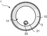
- FIG. 10 shows an end view of the catheter 1 shown in FIG. 9, taken along line XX.
- the flow path 30 may be formed by a second cylindrical member 31 provided separately.
- the second cylindrical member is a cylindrical member having an inner cavity.
- the lumen of the second cylindrical member 31 disposed in the lumen 11 of the outer tube 10 is the flow path 30.
- the second cylindrical member 31 may be placed in the inner cavity 11 of the outer tube 10.
- the catheter 1 can be easily made thinner.
- the second cylindrical member 31 may be placed outside the outer tube 10.
- the same synthetic resin or metal as the outer tube 10 can be used as the material constituting the second cylindrical member 31.
- the materials constituting the outer tube 10 and the first cylindrical member 40 and the materials constituting the second cylindrical member 31 may be the same or different.
- the bag-shaped body 20 preferably has an internal space 23 that communicates with the flow path 30.
- the fluid injected into the flow path 30 can flow into the internal space 23 formed in the bag-like body 20 .
- the internal space 23 is a space formed within the wall of the annular bag-like body 20.
- the internal space 23 is a space formed within the wall that forms the inner cavity 25 of the bag-shaped body 20.
- the internal space 23 exists within the wall of the bag-shaped body 20 in the entire circumferential direction. That is, it is preferable that the internal space 23 is a space communicating in the circumferential direction within the wall of the bag-like body 20.
- the internal space 23 may exist only in a part of the wall of the bag-like body 20 in the circumferential direction.
- the internal space 23 does not communicate with the inner cavity 11 of the outer tube 10. It is also preferable that the internal space 23 does not communicate with the inner cavity 25 of the bag-like body 20.
- the fluid injected into the flow path 30 can be made to flow efficiently into the internal space 23 formed in the bag-like body 20.
- the distal ends of the pouch 20 and the second cylindrical member 31 are fixed, and the pouch 20 is It is preferable to have a hole 24 that communicates the flow path 30 and the internal space 23. Thereby, the fluid injected into the flow path 30 can be injected into the internal space 23 of the bag-like body 20.
- the bag-like body 20 is provided distally from the distal end 10a of the outer tube 10, and the outer diameter becomes smaller toward the distal side. It is preferable to have a tapered portion.
- the bag-like body 20 may have a tapered portion only in a portion thereof, but the entire bag-like body 20, that is, the tapered portion from the distal end to the proximal end of the bag-like body 20. is more preferable.
- an X-ray opaque marker 3 is provided in at least one of the bag-like body 20 and a region extending 10 cm from the distal end of the outer tube 10. be able to. With this configuration, the position of the distal end of the catheter 1 can be visually recognized by using an X-ray imaging device.
- the X-ray opaque marker 3 may be provided only on the bag-like body 20, may be provided only in a region 10 cm proximal from the distal end 10a of the outer tube 10, or may be provided on both. It may be.
- the shape of the above-mentioned X-ray opaque marker is preferably cylindrical, and examples thereof include a cylindrical shape, a polygonal cylindrical shape, a C-shaped cross section with a notch in the tube, and a coil shape in which a wire is wound.
- the material constituting the X-ray opaque marker can be, for example, an X-ray opaque substance such as lead, barium, iodine, tungsten, gold, platinum, iridium, stainless steel, titanium, cobalt chromium alloy, etc. 10, the bag-like body 20, or a separately provided resin member, X-ray opaque particles such as barium sulfate may be dispersed therein.
- an X-ray opaque substance such as lead, barium, iodine, tungsten, gold, platinum, iridium, stainless steel, titanium, cobalt chromium alloy, etc. 10
- the bag-like body 20 or a separately provided resin member, X-ray opaque particles such as barium sulfate may be dispersed therein.
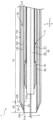
- FIG. 11 shows a sectional view showing another modification of the catheter shown in FIG. 4, and shows a side view of the guide wire 2 and second inner tube 52, which will be described later.
- FIG. 12 shows an end view of the catheter shown in FIG. 11 cut along line XII-XII.
- FIG. 13 is a cross-sectional view (partial side view) of the catheter shown in FIG. 11 in a state where it is pressurized at a predetermined pressure by injecting fluid into the flow path. Note that in FIGS. 11 and 13, the portion of the guide wire 2 disposed in the lumen of the inner tube 50 is indicated by a broken line.
- the inner tube 50 may be provided in the inner lumen 11 of the outer tube 10 so as to be movable relative to the outer tube 10.
- the inner tube 50 may have a lumen extending in the longitudinal direction x. Note that the inner lumen of the inner tube 50 can be used as an insertion path for the guide wire 2, etc., as shown in FIGS. 11 to 13.
- the inner tube 50 includes a first inner tube 51 disposed in the inner lumen 11 of the outer tube 10, and a second inner tube 51 disposed in the inner lumen of the first inner tube 51.
- a configuration in which a tube 52 is provided may also be used.
- the same synthetic resin, metal, etc. as the outer tube 10 can be used as the material constituting the inner tube 50.
- the material constituting the outer tube 10, the first cylindrical member 40, and the second cylindrical member 31 and the material constituting the inner tube 50 may be the same or different.
- the materials forming the first inner tube 51 and the second inner tube 52 may be the same or different.
- the inner surface of the second inner tube 52 preferably has a portion made of fluororesin or polyolefin resin. Only a part of the inner surface of the second inner tube 52 may be made of a fluororesin or a polyolefin resin, or the entire inner surface of the second inner tube 52 may be made of a fluororesin or a polyolefin resin. good. This allows the second inner tube 52 to easily slide on the guide wire 2, making it easier to improve the operability of the catheter 1.
- the catheter 1 may be configured to further include a control mechanism that suppresses movement of the inner tube 50 in the longitudinal direction x in the lumen 11 of the outer tube 10.
- the control mechanism allows the catheter 1 to be transported to the treatment section while suppressing the movement of the inner tube 50 in the longitudinal direction x in the inner lumen 11 of the outer tube 10. can be easily transported to the treatment section.
- control mechanism may include, for example, a mode in which the first cylindrical member 40 is provided with a gripping member that can grip the inner tube 50.
- a gripping member that can grip the inner tube 50.
- movement of the inner tube 50 in the longitudinal direction x in the lumen 11 of the outer tube 10 can be temporarily suppressed.
- the gripping member include a rubber member provided with a slit for gripping the inner tube 50, a clip made of rigid resin, and the like.
- an expansion member 60 that is provided at the distal portion of the inner tube 50 and expands in the radial direction y can be configured.
- expansion member 60 for example, a balloon or a stent can be used.
- the balloon is made of resin.
- resins constituting the balloon include polyamide resins, polyester resins, polyurethane resins, polyolefin resins, vinyl chloride resins, silicone resins, and natural rubber. These may be used alone or in combination of two or more. Among these, polyamide resins, polyester resins, and polyurethane resins are preferably used. An elastomer resin can be used to make the balloon thinner and more flexible.
- the distal end of the expansion member 60 has a second inner tube, as shown in FIGS. 11 and 13.
- the expansion member 60 is fixed to a distal portion of the inner tube 52, and a proximal end portion of the expansion member 60 is fixed to a distal portion of the first inner tube 51. Expanding member 60 can be expanded by flowing fluid into the lumen of first inner tube 51 .
- a stent is an expandable structure made of a network structure such as a mesh, and includes a plurality of struts.
- a stent can be formed from a pattern of interconnected structural elements that expand and contract, for example, circumferentially and axially.
- Stents are coiled types made of a single linear metal or polymeric material, types made by cutting out metal tubes or polymeric material tubes using a laser, etc., types assembled by welding linear parts, Examples include types made by weaving multiple metal wires.
- the stent is preferably constructed from a shape memory alloy or shape memory resin.
- the stent may be made of, for example, stainless steel such as SUS304 or SUS316, platinum, nickel, cobalt, chromium, titanium, tungsten, aluminum, gold, silver, Ni-Ti alloy, Co-Cr alloy, or the like.
- the stent may be a self-expanding stent or a balloon-expandable stent.
- the catheter 1 After the catheter 1 reaches the treatment area, by injecting fluid into the flow path 30, the bag-like body 20 is pressurized, and the minimum inner diameter of the bag-like body 20 becomes larger than before pressurization.
- the catheter 1 changes from the state shown in FIG. 11 to the state shown in FIG. 13 by injecting the fluid.
- the expansion member 60 placed in the lumen 11 of the outer tube 10 is transported to the treatment area in the state shown in FIG. 11, the smallest lumen of the bag-shaped body 20 is expanded as shown in FIG.
- the inner tube 50 including the expansion member 60 can be easily projected from the expanded diameter portion.
- the expansion member 60 it is preferable to use a balloon or a stent with a coating layer formed on the outer surface 61.
- the catheter 1 After the catheter 1 reaches the treatment area, by injecting fluid into the flow path 30, the bag-like body 20 is pressurized, and the minimum inner diameter of the bag-like body 20 becomes larger than before pressurization.
- the catheter 1 changes from the state shown in FIG. 11 to the state shown in FIG. 13 by injecting the fluid.
- the inner tube 50 provided with the balloon or stent can be easily protruded from the expanded diameter portion. For this reason, it is possible to easily prevent the coating layer provided on the outer surface 61 of the balloon or stent from peeling off when the balloon or stent is placed in the treatment area.
- the coating layer can be formed by applying a coating agent to the outer surface of the balloon or stent.
- the coating layer may be formed only on a part of the outer surface of the balloon or stent, or may be formed on the entire outer surface of the balloon or stent.
- the coating layer may contain a lubricating coating agent or a physiologically active agent.
- lubricating coating agents examples include silicone coating agents such as silicone and polydimethylsiloxane, sodium (meth)acrylate, butyl (meth)acrylate, methyl (meth)acrylate, ethyl (meth)acrylate, and propyl (meth)acrylate.
- silicone coating agents such as acrylate, octyl (meth)acrylate, and 2,2,2-trifluoroethyl methacrylate, fluorine coating agents such as polytetrafluoroethylene, hydrophilic coating agents such as polyvinylpyrrolidone, hyaluronic acid, and polyethylene glycol, etc. can be mentioned.
- bioactive drugs include paclitaxel, docetaxel, sirolimus, temsirolimus, everolimus, zotarolimus, biolimus A9, cilostazol, cyclosporine, NF- ⁇ B decoy oligo, and the like.
- a single physiologically active agent may be used, or a plurality of physiologically active agents may be used in combination.
- the balloon or stent may be coated with only a physiologically active drug, or may be coated with a physiologically active drug containing appropriate additives.
- the length from the distal end to the proximal end of the catheter 1 can be, for example, 200 mm or more, 250 mm or more, 300 mm or more, etc. Further, the length from the distal end to the proximal end of the catheter 1 can be, for example, 2500 mm or less, 2450 mm or less, 2400 mm or less, etc.
- the proximal end of the catheter 1 is provided with a hub 42, a controller used to operate the catheter 1, other devices, etc., and the relative positions of these members do not change. It may further include a mechanism that allows it to be fixed in place. Preferably, the mechanism is capable of fixing the relative position of at least two of the hub 42, the controller, and the other device.
- “possible to fix” means that it is possible to fix so that the relative position between at least two members does not move, or to move the relative position between at least two members. This means that it is also possible to release it from the fixed state so that it can be released from the fixed state.
Landscapes
- Health & Medical Sciences (AREA)
- Life Sciences & Earth Sciences (AREA)
- Heart & Thoracic Surgery (AREA)
- Animal Behavior & Ethology (AREA)
- Engineering & Computer Science (AREA)
- Anesthesiology (AREA)
- Biomedical Technology (AREA)
- Hematology (AREA)
- General Health & Medical Sciences (AREA)
- Public Health (AREA)
- Veterinary Medicine (AREA)
- Pulmonology (AREA)
- Biophysics (AREA)
- Child & Adolescent Psychology (AREA)
- Media Introduction/Drainage Providing Device (AREA)
Priority Applications (2)
| Application Number | Priority Date | Filing Date | Title |
|---|---|---|---|
| JP2024511646A JPWO2023189376A1 (https=) | 2022-03-29 | 2023-03-09 | |
| US18/891,829 US20250010031A1 (en) | 2022-03-29 | 2024-09-20 | Catheter |
Applications Claiming Priority (2)
| Application Number | Priority Date | Filing Date | Title |
|---|---|---|---|
| JP2022054634 | 2022-03-29 | ||
| JP2022-054634 | 2022-03-29 |
Related Child Applications (1)
| Application Number | Title | Priority Date | Filing Date |
|---|---|---|---|
| US18/891,829 Continuation US20250010031A1 (en) | 2022-03-29 | 2024-09-20 | Catheter |
Publications (1)
| Publication Number | Publication Date |
|---|---|
| WO2023189376A1 true WO2023189376A1 (ja) | 2023-10-05 |
Family
ID=88200667
Family Applications (1)
| Application Number | Title | Priority Date | Filing Date |
|---|---|---|---|
| PCT/JP2023/009132 Ceased WO2023189376A1 (ja) | 2022-03-29 | 2023-03-09 | カテーテル |
Country Status (2)
| Country | Link |
|---|---|
| JP (1) | JPWO2023189376A1 (https=) |
| WO (1) | WO2023189376A1 (https=) |
Citations (5)
| Publication number | Priority date | Publication date | Assignee | Title |
|---|---|---|---|---|
| DE2818119A1 (de) * | 1978-04-25 | 1979-11-08 | Reinhold Grundke | Katheter |
| US4822338A (en) * | 1987-09-03 | 1989-04-18 | Longmore Wayne D | Method of removing material from the stomach using a collapsible funnel |
| US5308325A (en) * | 1991-01-28 | 1994-05-03 | Corpak, Inc. | Retention balloon for percutaneous catheter |
| JP2009066178A (ja) * | 2007-09-13 | 2009-04-02 | Goodman Co Ltd | 吸引用カテーテル |
| JP2014230710A (ja) * | 2013-05-30 | 2014-12-11 | テルモ株式会社 | 治療方法 |
-
2023
- 2023-03-09 WO PCT/JP2023/009132 patent/WO2023189376A1/ja not_active Ceased
- 2023-03-09 JP JP2024511646A patent/JPWO2023189376A1/ja active Pending
Patent Citations (5)
| Publication number | Priority date | Publication date | Assignee | Title |
|---|---|---|---|---|
| DE2818119A1 (de) * | 1978-04-25 | 1979-11-08 | Reinhold Grundke | Katheter |
| US4822338A (en) * | 1987-09-03 | 1989-04-18 | Longmore Wayne D | Method of removing material from the stomach using a collapsible funnel |
| US5308325A (en) * | 1991-01-28 | 1994-05-03 | Corpak, Inc. | Retention balloon for percutaneous catheter |
| JP2009066178A (ja) * | 2007-09-13 | 2009-04-02 | Goodman Co Ltd | 吸引用カテーテル |
| JP2014230710A (ja) * | 2013-05-30 | 2014-12-11 | テルモ株式会社 | 治療方法 |
Also Published As
| Publication number | Publication date |
|---|---|
| JPWO2023189376A1 (https=) | 2023-10-05 |
Similar Documents
| Publication | Publication Date | Title |
|---|---|---|
| JP6463784B2 (ja) | 外転可能シース装置、システム、および、方法 | |
| US20110208284A1 (en) | Protective sleeve for a medical device, system comprising a protective sleeve and a medical device, and a method for the production thereof | |
| JP2008508936A (ja) | 管内ステント組立体およびこの定置方法 | |
| CN110575606A (zh) | 一种药物洗脱球囊扩张导管及使用方法 | |
| JP2022148511A (ja) | カテーテル | |
| JP2006218070A (ja) | カテーテル | |
| WO2023189376A1 (ja) | カテーテル | |
| JP7540142B2 (ja) | サポートカテーテルおよびチューブ | |
| JP2010525880A (ja) | バルーンカテーテル | |
| JP2025051095A (ja) | カテーテル | |
| US20250010031A1 (en) | Catheter | |
| JP2025051096A (ja) | カテーテル | |
| WO2025069714A1 (ja) | カテーテル | |
| JP2023147080A (ja) | カテーテル | |
| WO2023189377A1 (ja) | カテーテル | |
| JP2023147081A (ja) | カテーテル | |
| WO2023189378A1 (ja) | カテーテル | |
| JP5799488B2 (ja) | 血管内薬剤溶出カテーテル | |
| ES3059306T3 (en) | Catheter braid wire with variable cross-section shape | |
| CN121490249A (zh) | 导管组装体 | |
| JP2025149411A (ja) | カテーテル | |
| WO2025150326A1 (ja) | 医療用具 | |
| JP2014069034A (ja) | バルーンカテーテル | |
| JP2023143226A (ja) | 医療用管状体搬送装置 | |
| JP2024040729A (ja) | バルーンカテーテル |
Legal Events
| Date | Code | Title | Description |
|---|---|---|---|
| 121 | Ep: the epo has been informed by wipo that ep was designated in this application |
Ref document number: 23779402 Country of ref document: EP Kind code of ref document: A1 |
|
| ENP | Entry into the national phase |
Ref document number: 2024511646 Country of ref document: JP Kind code of ref document: A |
|
| NENP | Non-entry into the national phase |
Ref country code: DE |
|
| 122 | Ep: pct application non-entry in european phase |
Ref document number: 23779402 Country of ref document: EP Kind code of ref document: A1 |