WO2023189285A1 - 回転子及び電動機 - Google Patents
回転子及び電動機 Download PDFInfo
- Publication number
- WO2023189285A1 WO2023189285A1 PCT/JP2023/008571 JP2023008571W WO2023189285A1 WO 2023189285 A1 WO2023189285 A1 WO 2023189285A1 JP 2023008571 W JP2023008571 W JP 2023008571W WO 2023189285 A1 WO2023189285 A1 WO 2023189285A1
- Authority
- WO
- WIPO (PCT)
- Prior art keywords
- magnet
- rotor
- hole
- rotor core
- placement hole
- Prior art date
- Legal status (The legal status is an assumption and is not a legal conclusion. Google has not performed a legal analysis and makes no representation as to the accuracy of the status listed.)
- Ceased
Links
Images



Classifications
-
- H—ELECTRICITY
- H02—GENERATION; CONVERSION OR DISTRIBUTION OF ELECTRIC POWER
- H02K—DYNAMO-ELECTRIC MACHINES
- H02K1/00—Details of the magnetic circuit
- H02K1/06—Details of the magnetic circuit characterised by the shape, form or construction
- H02K1/22—Rotating parts of the magnetic circuit
- H02K1/27—Rotor cores with permanent magnets
- H02K1/2706—Inner rotors
- H02K1/272—Inner rotors the magnetisation axis of the magnets being perpendicular to the rotor axis
- H02K1/274—Inner rotors the magnetisation axis of the magnets being perpendicular to the rotor axis the rotor consisting of two or more circumferentially positioned magnets
- H02K1/2753—Inner rotors the magnetisation axis of the magnets being perpendicular to the rotor axis the rotor consisting of two or more circumferentially positioned magnets the rotor consisting of magnets or groups of magnets arranged with alternating polarity
- H02K1/276—Magnets embedded in the magnetic core, e.g. interior permanent magnets [IPM]
Definitions
- the present disclosure relates to a rotor and an electric motor, and particularly relates to a rotor including a permanent magnet and an electric motor including the rotor.
- Patent Document 1 discloses a method for positioning magnets of a rotor of an electric motor.
- a rotor core divided in the direction of the rotation axis is prepared, a permanent magnet and adhesive are inserted into the magnet insertion hole, and the permanent magnet is positioned within the magnet insertion hole by twisting the divided rotor core in the rotation direction.
- Patent Document 1 when the divided rotor core is twisted in the rotational direction, the permanent magnet moves together with the adhesive within the magnet insertion hole, so that the corner portion hits the wall of the magnet insertion hole, resulting in line contact instead of surface contact. It becomes easier. If the contact area between both members is reduced in this manner, the rotor core is deformed during high-speed rotation, which causes torque ripple, thereby reducing the magnetic flux that can be taken out.
- the present disclosure has been made in view of the above points, and an object of the present disclosure is to provide a rotor and an electric motor that can hold permanent magnets in an appropriate posture.
- a rotor includes a rotating shaft, a first rotor core, a second rotor core, and a permanent magnet.
- the rotating shaft has an axial center as its center of rotation.
- the first rotor core is fixed to the rotating shaft and has a first magnet placement hole formed therein.
- the second rotor core is aligned with the first rotor core in the axial direction of the rotary shaft and is fixed to the rotary shaft, and has a second magnet placement hole corresponding to the first magnet placement hole. It is formed.
- the permanent magnet is arranged in a set of the first magnet arrangement hole and the second magnet arrangement hole.
- the positions of the first magnet arrangement hole and the second magnet arrangement hole are shifted from each other in the circumferential direction perpendicular to the axial direction of the rotating shaft, so that the permanent magnet is located between the first magnet arrangement hole and the second magnet arrangement hole. 2 is positioned within the magnet placement hole.
- An electric motor includes the rotor and stator.
- the permanent magnets can be held in an appropriate posture.
- FIG. 1 is a schematic top view of an electric motor according to an embodiment.
- FIG. 2 is a perspective view of the rotor according to the embodiment.
- FIG. 3 is a partially enlarged view of FIG. 1, and is a diagram showing the positional relationship between the first magnet placement hole and the second magnet placement hole.
- FIG. 4 is a partial cross-sectional view of the rotor according to the embodiment.
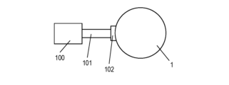
- FIG. 5 is a schematic diagram of an electric motor and a power source that supplies current to the electric motor according to the embodiment.
- FIG. 6 is a partial sectional view of a rotor according to a modification of the embodiment.
- the electric motor 1 is an inner rotor type motor.
- FIG. 1 is a schematic top view of an electric motor 1 according to an embodiment.
- FIG. 2 is a perspective view of the rotor 3 according to the embodiment.
- FIG. 3 is a partially enlarged view of FIG. 1, and is a diagram showing the positional relationship between the first magnet placement hole 13 and the second magnet placement hole 18.
- the electric motor 1 has a stator 2 and a rotor 3.
- the direction in which the axis 14 (described later) of the rotating shaft 10 (described later) extends is referred to as an axial direction A1
- the circumferential direction of the rotor 3 is referred to as a circumferential direction C1.
- a direction along a line segment connecting a point on a plane perpendicular to the axis 14 and an intersection of the plane and the axis 14 is referred to as a radial direction F1.
- the axial direction A1, the circumferential direction C1, and the radial direction F1 are orthogonal to each other.
- the stator 2 includes a stator core 4 and a plurality of (nine in FIG. 1) coils 6.
- the stator core 4 is a laminated core in which a plurality of electromagnetic steel plates are laminated in the thickness direction.
- the stator core 4 is formed into a substantially cylindrical column shape.
- the stator core 4 includes an annular core back 7 and a plurality of (nine teeth in FIG. 1) teeth 8.
- the plurality of teeth 8 are arranged on the inner peripheral surface of the core back 7 at regular intervals along the circumferential direction C1, and extend toward the axial center 14 in the radial direction F1.
- the plurality of coils 6 correspond to the plurality of teeth 8, and each coil 6 is formed by winding a conductor around the corresponding tooth 8.
- the rotor 3 is an IPM (Interior Permanent Magnet) type rotor in which a permanent magnet is embedded inside the rotor core.
- the rotor 3 is arranged in the radial direction F1 of the stator 2 and toward the axis 14, and includes a rotor core 9, a rotating shaft 10, and a plurality of (10 in FIG. 1) permanent magnets 11. .
- FIG. 5 shows a schematic diagram of a power supply 100 that supplies current to the electric motor 1.
- the electric motor 1 operates as follows.
- a cable 101 extends from a power supply 100 to the electric motor 1, and current is supplied through a power supply connection part 102. More specifically, three-phase currents having a phase difference of 120 degrees in electrical angle are supplied to the plurality of coils 6 through the power supply connection part 102, the stator 2 is excited, and a rotating magnetic field is generated.
- This rotating magnetic field interacts with the magnetic field generated by the permanent magnet 11 provided on the rotor 3 to generate rotational torque in the rotor 3, and as a result, the rotor 3 rotates around the axis 14. .
- FIG. 4 is a partial sectional view of the rotor 3 according to the embodiment.
- FIG. 4 is a cross-sectional view taken along a plane passing through the rotor core 9 and the permanent magnets 11, including the line IV-IV perpendicular to the radial direction F1, and along the circumferential direction C1 in FIG. Note that the IV-IV line segment is also shown in FIG.
- the rotor core 9 includes a first rotor core 21 and a second rotor core 22, which are divided in the axial direction A1 of the rotating shaft 10.
- Each of the first rotor core 21 and the second rotor core 22 is a laminated core in which a plurality of electromagnetic steel plates 17 are laminated in the thickness direction.
- Each of the first rotor core 21 and the second rotor core 22 has a circular center shaft hole 12 and is formed into a cylindrical shape.
- the first rotor core 21 and the second rotor core 22 have the same thickness in the axial direction A1, and the second rotor core 22 is arranged below the first rotor core 21 in the axial direction A1. There is.
- a plurality of first magnet arrangement holes 13 arranged in the circumferential direction C1 are formed in the first rotor core 21.
- the first magnet arrangement hole 13 has a substantially rectangular opening shape, and specifically, the longitudinal direction extends in the radial direction. In this embodiment, the first magnet arrangement hole 13 penetrates in the axial direction A1.
- a plurality of second magnet arrangement holes 18 are formed in the second rotor core 22 and arranged in the circumferential direction C1.
- the second magnet arrangement hole 18 has a substantially rectangular opening shape, and specifically, the longitudinal direction extends in the radial direction.
- the second magnet arrangement hole 18 has the same size, shape, radial and circumferential position, and arrangement interval in the circumferential direction C1 as the first magnet arrangement hole 13.
- the first rotor core 21 and the second rotor core 22 are stacked such that the first magnet placement hole 13 and the second magnet placement hole 18 overlap.
- the second magnet arrangement hole 18 penetrates in the axial direction A1.
- the rotating shaft 10 is a cylindrical member and has an axis 14 that is the center of rotation.
- the rotating shaft 10 is inserted into the central shaft hole 12 of the first rotor core 21 and the second rotor core 22 and is fixed therein.
- Each of the plurality of (10 in FIG. 1) permanent magnets 11 is arranged and fixed in a corresponding one of the plurality of first magnet arrangement holes 13 and second magnet arrangement holes 18 of the rotor core 9. .
- Each permanent magnet 11 has, for example, a rectangular parallelepiped shape. The cross-sectional area of the permanent magnet 11 is smaller than the opening area of the first magnet placement hole 13 and the second magnet placement hole 18 .
- a samarium-cobalt permanent magnet, a neodymium magnet, or the like can be used as the permanent magnet 11, Neodymium magnets are suitable for use in automobile motors.
- the positions of the first magnet arrangement hole 13 and the second magnet arrangement hole 18 are slightly shifted in the circumferential direction C1, as shown in FIGS. 3 and 4. Specifically, the second magnet arrangement hole 18 is offset from the first magnet arrangement hole 13 in the counterclockwise direction in the circumferential direction C1 in the plane of the paper of FIG.
- the permanent magnets 11 are arranged in the first magnet arrangement hole 13 and the second magnet arrangement hole 18 so as to be located on average at the center in the circumferential direction.
- the above configuration will be explained in detail below.
- the clockwise direction along the circumferential direction C1 is simply referred to as the "clockwise direction”
- the counterclockwise direction along the circumferential direction C1 is referred to as "clockwise direction”.
- the permanent magnet 11 is in contact with the first inner surface 131 (the counterclockwise side surface in the circumferential direction C1) of the first magnet placement hole 13 of the first rotor core 21, and , is in contact with the third inner surface 181 (clockwise side surface in the circumferential direction C1) of the second magnet arrangement hole 18 of the second rotor core 22.
- the permanent magnets 11 are inserted into the first magnet arrangement holes 13 of the first rotor core 21 from both sides of the circumferential direction C1 (clockwise side of the circumferential direction C1 and counterclockwise side of the circumferential direction C1). Then, it comes into contact with the second magnet arrangement hole 18 of the second rotor core 22 and is positioned within the first magnet arrangement hole 13 and the second magnet arrangement hole 18 .
- the permanent magnet 11 has a first side surface 111 and a second side surface 112, as shown in FIGS. 3 and 4.
- the first side surface 111 and the second side surface 112 face opposite sides in the circumferential direction C1.
- the upper portion 111A of the first side surface 111 is in contact with the first inner surface 131 of the first magnet placement hole 13.
- the lower portion 111B of the first side surface 111 has a fourth inner surface 182 of the first magnet arrangement hole 13 (the fourth inner surface 182 is recessed counterclockwise in the circumferential direction C1 when viewed from the first inner surface 131).
- the first gap 31 is provided between the first gap 31 and the first gap 31 .
- the lower portion 112B of the second side surface 112 includes a third inner surface 181 of the second magnet arrangement hole 18 (the third inner surface 181 protrudes counterclockwise in the circumferential direction C1 when viewed from the second inner surface 132). ) is in contact with the The upper portion 112A of the second side surface 112 is the second inner surface 132 of the second magnet arrangement hole 18 (the second inner surface 132 is recessed in the circumferential direction C1 counterclockwise when viewed from the third inner surface 181). They are arranged with a second gap 32 between them.
- the rotor 3 has a first adhesive layer 25 and a second adhesive layer 26 for fixing the permanent magnets 11 to the first magnet placement hole 13 and the second magnet placement hole 18.
- the first adhesive layer 25 and the second adhesive layer 26 are, for example, adhesives made of thermosetting resin, and specifically may be epoxy resin or silicone resin.
- the first adhesive layer 25 is arranged in the second gap 32, and the second adhesive layer 26 is arranged in the first gap 31. Note that between the upper portion 111A of the first side surface 111 and the first inner surface 131 of the first magnet placement hole 13, and between the lower portion 112B of the second side surface 112 and the third inner surface 181 of the second magnet placement hole 18, No adhesive is placed between them.
- the permanent magnet 11 is arranged in the first magnet arrangement hole 13 and the second magnet arrangement hole 18 so as to be parallel to the axial direction A1.
- parallel here means that the longitudinal axis of the permanent magnet 11 is parallel to the axial direction A1, and includes, for example, an inclination of 5 degrees or less.
- parallel here means that the longitudinal axis of the permanent magnet 11 is completely parallel to the axial direction A1 (the angle between the longitudinal axis of the permanent magnet 11 and the axial direction A1 is 0 degrees). ) and cases where the angle between the longitudinal axis of the permanent magnet 11 and the axial direction A1 is 5 degrees or less.
- the upper portion 111A of the first side surface 111 and the first inner side surface 131 of the first magnet placement hole 13 are in surface contact.
- the lower portion 112B of the second side surface 112 and the third inner side surface 181 of the second magnet placement hole 18 are in surface contact.
- surface contact refers to a relationship in which the surfaces are in contact with or close to each other and support each other.
- Rotor manufacturing method A manufacturing method of the rotor 3 will be explained. Note that the manufacturing method described below is an example and does not limit the present disclosure.
- a first rotor core 21 and a second rotor core 22 are prepared. Specifically, a plurality of electromagnetic steel plates 17 are formed by punching out an original electromagnetic steel plate using a press machine, and then the electromagnetic steel plates 17 are laminated to produce the first rotor core 21 and the second rotor core 22. do.
- the permanent magnets 11 are inserted into each set of the first magnet arrangement hole 13 and the second magnet arrangement hole 18 in the stacked first rotor core 21 and second rotor core 22. At this time, the first magnet arrangement hole 13 and the second magnet arrangement hole 18 are aligned with each other.
- the first rotor core 21 and the second rotor core 22 are rotated relative to each other in the circumferential direction C1.
- the upper portion 111A of the first side surface 111 of the permanent magnet 11 comes into surface contact with the first inner side surface 131 of the first magnet placement hole 13 in the circumferential direction C1.
- the lower portion 112B of the second side surface 112 of the permanent magnet 11 makes surface contact with the third inner side surface 181 of the second magnet placement hole 18 in the circumferential direction C1.
- the permanent magnets 11 are fixed to the rotor core 9 by applying the second adhesive layer 26 and the first adhesive layer 25 to the first gap 31 and the second gap 32, respectively.
- the rotating shaft 10 is attached to the first rotor core 21 and the second rotor core 22. Specifically, the rotating shaft 10 is fixed to the center shaft hole 12 of the first rotor core 21 and the second rotor core 22.
- FIG. 6 is a partial sectional view of the rotor 3 according to a modification of the embodiment. At least a portion between the upper part 111A of the first side surface 111 and the first inner surface 131 of the first magnet arrangement hole 13, and the lower part 112B of the second side surface 112 and the third inner part of the second magnet arrangement hole 18.
- the third adhesive layer 27 and the fourth adhesive layer 28 may be arranged at least in part between the side surface 181 and the side surface 181 .
- the amount of adhesive in the third adhesive layer 27 and the fourth adhesive layer 28 is smaller than that in the first adhesive layer 25 and the second adhesive layer 26, respectively.
- the structure of the permanent magnet, the first magnet arrangement hole, and the second magnet arrangement hole described above was realized in all the sets of the first magnet arrangement hole and the second magnet arrangement hole, but the above structure It may be realized only in some sets of the arrangement hole and the second magnet arrangement hole.
- the thickness in the axial direction of the first rotor core and the second rotor core may be different.
- the rotor core may be divided into three or more parts in the axial direction.
- the adhesive may be omitted.
- the shape, number, and position of the magnet placement holes and permanent magnets are not limited.
- the permanent magnet may have a rectangular shape with a short radial length in plan view.
- the rotor core may be a powder core whose main component is a powder material formed by pressure-molding a powdered magnetic material.
- the rotor (3) includes a rotating shaft (10), a first rotor core (21), and a second rotor core (22).
- the rotating shaft (10) rotates around the axial center (14).
- the first rotor core (21) is fixed to the rotating shaft (10), and has a first magnet placement hole (13) formed therein.
- the second rotor core (22) is fixed to the rotary shaft (10) in line with the first rotor core (21) in the axial direction of the rotary shaft (10), and is fixed to the first magnet arrangement hole (13).
- ) is formed with a second magnet arrangement hole (18) corresponding to the second magnet arrangement hole (18).
- the permanent magnet (11) is arranged in a set of a first magnet arrangement hole (13) and a second magnet arrangement hole (18).
- the permanent magnet (11) are positioned within the first magnet placement hole (13) and the second magnet placement hole (18).
- the permanent magnet (11) can be positioned within the set of the first magnet placement hole (13) and the second magnet placement hole (18).
- the rotor (3) according to the second aspect of the present disclosure has an adhesive (25) that fixes the permanent magnet (11) to the first magnet placement hole (13) and the second magnet placement hole (18). , 26).
- the permanent magnet (11) can be fixed within the set of the first magnet placement hole (13) and the second magnet placement hole (18) using the adhesive (25, 26).
- the permanent magnet (11) is connected to the first inner surface (131) of the first magnet arrangement hole (13) in the circumferential direction (C1).
- a first side surface (111, 111A) that is close to or in contact with each other, and a second side surface that is arranged with a gap (32) from the second inner surface (132) of the first magnet placement hole (13) in the circumferential direction (C1). (112, 112A).
- the adhesive (25, 26) has a first adhesive (25) disposed in at least a portion of the gap (32).
- the adhesive by disposing the adhesive (25) in the gap (32), the adhesive can be brought into contact with the members on both sides over a large area.
- the adhesive is applied to the first side surface (111A) of the permanent magnet (11) and the first inner surface of the first magnet placement hole (13). (131).
- the amount of adhesive used can be reduced.
- the first side surface (111, 111A) of the permanent magnet (11) is the first inner surface ( 131).
- the amount of adhesive is smaller than the first adhesive (25), and the amount of adhesive is between the first side surface (111, 111A) of the permanent magnet (11) and the first inner surface (131) of the first magnet placement hole (13). It further includes a second adhesive disposed at least partially in between.
- the permanent magnet (11) can be firmly fixed in the first magnet placement hole (13).
- the second side surface (112, 112B) of the permanent magnet (11) is arranged in the circumferential direction (C1). Close to or in contact with the third inner surface (181) of the second magnet arrangement hole (18).
- the first side surface (111, 111B) of the permanent magnet (11) is arranged with a gap (31) from the fourth inner surface (182) of the second magnet arrangement hole (18) in the circumferential direction (C1). .
- the permanent magnet (11) is supported by the first magnet placement hole (13) and the second magnet placement hole (18) on both sides in the circumferential direction. Moreover, the permanent magnet (11) secures a gap with respect to the first magnet arrangement hole (13) and the second magnet arrangement hole (18) on both sides in the circumferential direction.
- the first side surface (111, 111A) of the permanent magnet (11) is arranged such that the first magnet arrangement hole ( It is in surface contact with the first inner surface (131) of 13).
- the attitude of the permanent magnet (11) is stabilized.
- the permanent magnet (11) is arranged in the first magnet so as to be parallel to the axial direction. It is arranged in the hole (13) and the second magnet arrangement hole (18).
- the attitude of the permanent magnet (11) is stabilized.
- At least one of the first rotor core (21) and the second rotor core (22) includes: It consists of a plurality of laminated electromagnetic steel sheets (17).
- the first rotor core (21) and the second rotor core (22) can be manufactured relatively inexpensively.
- the first rotor core (21) has a plurality of first magnet placement holes (13).
- the second rotor core (22) has a plurality of second magnet placement holes (18).
- the plurality of first magnet arrangement holes (13) are lined up in the circumferential direction (C1) of the first rotor core (21).
- the plurality of second magnet arrangement holes (18) are lined up in the circumferential direction (C1) of the second rotor core, and correspond to the plurality of first magnet arrangement holes (13), respectively.
- the positioning of the plurality of permanent magnets (11) is performed simultaneously.
- An electric motor (1) according to an eleventh aspect of the present disclosure includes a rotor (3) and a stator (4) according to any one of the first to tenth aspects.
- the attitude of the permanent magnet (11) in the rotor (3) is stabilized.
- the permanent magnets included in the rotor can be held in an appropriate posture. Therefore, the rotor core can be prevented from being deformed during high-speed rotation of the rotor, thereby minimizing the generation of torque ripple and suppressing a decrease in the magnetic flux that can be taken out.
- the rotor and electric motor of the present disclosure are industrially useful.
Landscapes
- Engineering & Computer Science (AREA)
- Power Engineering (AREA)
- Permanent Field Magnets Of Synchronous Machinery (AREA)
Priority Applications (2)
| Application Number | Priority Date | Filing Date | Title |
|---|---|---|---|
| JP2024511597A JPWO2023189285A1 (https=) | 2022-03-30 | 2023-03-07 | |
| CN202380028398.7A CN118891807A (zh) | 2022-03-30 | 2023-03-07 | 转子及电动机 |
Applications Claiming Priority (2)
| Application Number | Priority Date | Filing Date | Title |
|---|---|---|---|
| JP2022057424 | 2022-03-30 | ||
| JP2022-057424 | 2022-03-30 |
Publications (1)
| Publication Number | Publication Date |
|---|---|
| WO2023189285A1 true WO2023189285A1 (ja) | 2023-10-05 |
Family
ID=88201376
Family Applications (1)
| Application Number | Title | Priority Date | Filing Date |
|---|---|---|---|
| PCT/JP2023/008571 Ceased WO2023189285A1 (ja) | 2022-03-30 | 2023-03-07 | 回転子及び電動機 |
Country Status (3)
| Country | Link |
|---|---|
| JP (1) | JPWO2023189285A1 (https=) |
| CN (1) | CN118891807A (https=) |
| WO (1) | WO2023189285A1 (https=) |
Cited By (1)
| Publication number | Priority date | Publication date | Assignee | Title |
|---|---|---|---|---|
| WO2025094525A1 (ja) * | 2023-10-30 | 2025-05-08 | パナソニックIpマネジメント株式会社 | ロータ、モータ及びロータの製造方法 |
Citations (1)
| Publication number | Priority date | Publication date | Assignee | Title |
|---|---|---|---|---|
| JP2011083188A (ja) * | 2010-11-24 | 2011-04-21 | Hitachi Automotive Systems Ltd | 回転電機および電気自動車 |
-
2023
- 2023-03-07 JP JP2024511597A patent/JPWO2023189285A1/ja active Pending
- 2023-03-07 CN CN202380028398.7A patent/CN118891807A/zh active Pending
- 2023-03-07 WO PCT/JP2023/008571 patent/WO2023189285A1/ja not_active Ceased
Patent Citations (1)
| Publication number | Priority date | Publication date | Assignee | Title |
|---|---|---|---|---|
| JP2011083188A (ja) * | 2010-11-24 | 2011-04-21 | Hitachi Automotive Systems Ltd | 回転電機および電気自動車 |
Cited By (1)
| Publication number | Priority date | Publication date | Assignee | Title |
|---|---|---|---|---|
| WO2025094525A1 (ja) * | 2023-10-30 | 2025-05-08 | パナソニックIpマネジメント株式会社 | ロータ、モータ及びロータの製造方法 |
Also Published As
| Publication number | Publication date |
|---|---|
| JPWO2023189285A1 (https=) | 2023-10-05 |
| CN118891807A (zh) | 2024-11-01 |
Similar Documents
| Publication | Publication Date | Title |
|---|---|---|
| JP6667084B2 (ja) | 表面磁石型モータ | |
| JP6380310B2 (ja) | 回転電機のステータ | |
| JP2009189163A (ja) | モータ | |
| WO2009119734A1 (ja) | モータ | |
| JP4586717B2 (ja) | モータ | |
| JPWO2018225296A1 (ja) | ロータ及び回転機 | |
| JP2008193842A (ja) | アキシャルギャップ型回転電機 | |
| CN113039704B (zh) | 定子及使用该定子的电动机 | |
| JP2021129443A (ja) | モータ | |
| WO2023189285A1 (ja) | 回転子及び電動機 | |
| JP4303579B2 (ja) | 三次元ステーター構造の回転機 | |
| WO2023276514A1 (ja) | 回転子及びその製造方法、並びに電動機 | |
| CN106208456A (zh) | 转子组件及包括该转子组件的马达 | |
| JP2020145853A (ja) | 空芯コイル及び空芯コイルの製造方法並びにステータ | |
| WO2018180345A1 (ja) | 電動モータ用ステータおよび電動モータ | |
| JP2018160956A (ja) | ブラシレスモータ | |
| JP6687272B1 (ja) | 回転電機、及びコアの製造方法 | |
| CN110574257A (zh) | 电动马达用定子和电动马达 | |
| CN102761219B (zh) | 旋转电机及转子 | |
| JP2001218436A (ja) | 永久磁石電動機 | |
| JP7850892B2 (ja) | 回転子及び電動機 | |
| US20260039164A1 (en) | Coil body, armature and rotary electric machine | |
| JP2020145837A (ja) | ステータの製造方法 | |
| WO2022255038A1 (ja) | 回転子及び電動機 | |
| WO2019146450A1 (ja) | インシュレータ及びそれを備えたステータ、モータ |
Legal Events
| Date | Code | Title | Description |
|---|---|---|---|
| 121 | Ep: the epo has been informed by wipo that ep was designated in this application |
Ref document number: 23779312 Country of ref document: EP Kind code of ref document: A1 |
|
| ENP | Entry into the national phase |
Ref document number: 2024511597 Country of ref document: JP Kind code of ref document: A |
|
| WWE | Wipo information: entry into national phase |
Ref document number: 202380028398.7 Country of ref document: CN |
|
| NENP | Non-entry into the national phase |
Ref country code: DE |
|
| 122 | Ep: pct application non-entry in european phase |
Ref document number: 23779312 Country of ref document: EP Kind code of ref document: A1 |