WO2023188902A1 - モータ及び回転翼装置 - Google Patents
モータ及び回転翼装置 Download PDFInfo
- Publication number
- WO2023188902A1 WO2023188902A1 PCT/JP2023/004966 JP2023004966W WO2023188902A1 WO 2023188902 A1 WO2023188902 A1 WO 2023188902A1 JP 2023004966 W JP2023004966 W JP 2023004966W WO 2023188902 A1 WO2023188902 A1 WO 2023188902A1
- Authority
- WO
- WIPO (PCT)
- Prior art keywords
- holder
- protrusion
- motor
- opening
- housing
- Prior art date
- Legal status (The legal status is an assumption and is not a legal conclusion. Google has not performed a legal analysis and makes no representation as to the accuracy of the status listed.)
- Ceased
Links
Images




Classifications
-
- B—PERFORMING OPERATIONS; TRANSPORTING
- B64—AIRCRAFT; AVIATION; COSMONAUTICS
- B64U—UNMANNED AERIAL VEHICLES [UAV]; EQUIPMENT THEREFOR
- B64U30/00—Means for producing lift; Empennages; Arrangements thereof
- B64U30/20—Rotors; Rotor supports
- B64U30/29—Constructional aspects of rotors or rotor supports; Arrangements thereof
-
- B—PERFORMING OPERATIONS; TRANSPORTING
- B64—AIRCRAFT; AVIATION; COSMONAUTICS
- B64C—AEROPLANES; HELICOPTERS
- B64C27/00—Rotorcraft; Rotors peculiar thereto
- B64C27/04—Helicopters
-
- H—ELECTRICITY
- H02—GENERATION; CONVERSION OR DISTRIBUTION OF ELECTRIC POWER
- H02K—DYNAMO-ELECTRIC MACHINES
- H02K1/00—Details of the magnetic circuit
- H02K1/06—Details of the magnetic circuit characterised by the shape, form or construction
- H02K1/12—Stationary parts of the magnetic circuit
- H02K1/16—Stator cores with slots for windings
-
- H—ELECTRICITY
- H02—GENERATION; CONVERSION OR DISTRIBUTION OF ELECTRIC POWER
- H02K—DYNAMO-ELECTRIC MACHINES
- H02K1/00—Details of the magnetic circuit
- H02K1/06—Details of the magnetic circuit characterised by the shape, form or construction
- H02K1/22—Rotating parts of the magnetic circuit
- H02K1/27—Rotor cores with permanent magnets
-
- H—ELECTRICITY
- H02—GENERATION; CONVERSION OR DISTRIBUTION OF ELECTRIC POWER
- H02K—DYNAMO-ELECTRIC MACHINES
- H02K1/00—Details of the magnetic circuit
- H02K1/06—Details of the magnetic circuit characterised by the shape, form or construction
- H02K1/22—Rotating parts of the magnetic circuit
- H02K1/27—Rotor cores with permanent magnets
- H02K1/2786—Outer rotors
- H02K1/2787—Outer rotors the magnetisation axis of the magnets being perpendicular to the rotor axis
- H02K1/2789—Outer rotors the magnetisation axis of the magnets being perpendicular to the rotor axis the rotor consisting of two or more circumferentially positioned magnets
- H02K1/2791—Surface mounted magnets; Inset magnets
-
- H—ELECTRICITY
- H02—GENERATION; CONVERSION OR DISTRIBUTION OF ELECTRIC POWER
- H02K—DYNAMO-ELECTRIC MACHINES
- H02K5/00—Casings; Enclosures; Supports
- H02K5/04—Casings or enclosures characterised by the shape, form or construction thereof
- H02K5/10—Casings or enclosures characterised by the shape, form or construction thereof with arrangements for protection from ingress, e.g. water or fingers
-
- H—ELECTRICITY
- H02—GENERATION; CONVERSION OR DISTRIBUTION OF ELECTRIC POWER
- H02K—DYNAMO-ELECTRIC MACHINES
- H02K5/00—Casings; Enclosures; Supports
- H02K5/04—Casings or enclosures characterised by the shape, form or construction thereof
- H02K5/16—Means for supporting bearings, e.g. insulating supports or means for fitting bearings in the bearing-shields
- H02K5/173—Means for supporting bearings, e.g. insulating supports or means for fitting bearings in the bearing-shields using bearings with rolling contact, e.g. ball bearings
- H02K5/1735—Means for supporting bearings, e.g. insulating supports or means for fitting bearings in the bearing-shields using bearings with rolling contact, e.g. ball bearings radially supporting the rotary shaft at only one end of the rotor
-
- H—ELECTRICITY
- H02—GENERATION; CONVERSION OR DISTRIBUTION OF ELECTRIC POWER
- H02K—DYNAMO-ELECTRIC MACHINES
- H02K7/00—Arrangements for handling mechanical energy structurally associated with dynamo-electric machines, e.g. structural association with mechanical driving motors or auxiliary dynamo-electric machines
- H02K7/14—Structural association with mechanical loads, e.g. with hand-held machine tools or fans
Definitions
- the present invention relates to a motor and a rotary blade device having the motor.
- a motor that has a rotor hole section partitioned by a rotor rib section that constitutes a part of the rotor.
- the rotor hole forms a path for air to a stator such as a stator core and coils housed within the rotor.
- a stator such as a stator core and coils housed within the rotor.
- the air path exposes the stator to the outside.
- UAV unmanned aerial vehicle
- the present invention has been made in view of the above problems, and an object of the present invention is to provide a motor and a rotary blade device that can improve dustproof and waterproof performance.
- the motor according to the present invention includes: annular rotor; a stator facing the rotor;
- the rotor includes a magnet and a housing that covers the magnet,
- the stator includes a coil and a holder that holds the coil,
- the housing has a first protrusion that protrudes toward the holder,
- the holder has a second protrusion that protrudes toward the housing,
- the second protrusion has a second protrusion that faces the first protrusion with a gap in the radial direction.
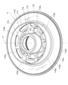
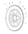
- FIG. 1 is a perspective view schematically showing the appearance of a motor 1 according to an embodiment of the present invention.
- 2 is a perspective cross-sectional view taken along line 2-2 in FIG. 1.
- FIG. FIG. 2 is a perspective view of the holder 11 alone, schematically showing the configuration of the holder 11.
- FIG. 2 is a perspective cross-sectional view taken along line 4-4 in FIG. 1.
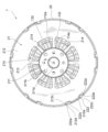
- FIG. 1 is a plan view schematically showing the configuration of a motor 1 according to an embodiment of the present invention.
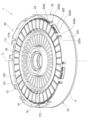
- FIG. 2 is a perspective view of the motor 1 schematically showing a state in which a housing 21 is removed from the motor 1 according to an embodiment of the present invention.
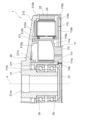
- 2 is a partial cross-sectional view taken along line 7-7 in FIG. 1.
- FIG. FIG. 2 is a perspective view of the housing 21 alone, schematically showing the configuration of the housing 21.
- FIG. 1 is a cross-sectional view schematically showing the structure of a rotary blade device 2 according to an embodiment of the present invention.
- FIG. 1 is a perspective view schematically showing the appearance of a motor 1 according to an embodiment of the present invention.
- FIG. 2 is a perspective cross-sectional view taken along line 2-2 in FIG.
- the motor 1 is, for example, an outer rotor type brushless motor mounted on, for example, an unmanned aerial vehicle (UAV), and has, for example, a generally flat cylindrical profile as shown in FIGS. 1 and 2.
- the motor 1 includes a stator 10 and an annular rotor 20 that is rotatably supported by the stator 10 around an axis X and faces the stator 10.
- the direction in which the axis X extends is defined as the axis X direction.
- one direction side is defined as an upper side
- the other direction side is defined as a lower side.
- the side where the stator 10 is arranged is defined as the lower side
- the side where the rotor 20 is arranged is defined as the upper side.
- the direction perpendicular to the axis X is defined as the radial direction, and in this radial direction, the side facing the axis X is defined as the inner circumferential side, or the inner side in the radial direction, and the side away from the axis X is defined as the outer circumferential side, or , is defined as the outer side in the radial direction. Further, the direction around the axis X is defined as the circumferential direction.
- FIG. 3 is a perspective view of the holder 11 alone, schematically showing the configuration of the holder 11.
- the holder 11 includes an inner wall portion 111 defined on the inner circumference side, a mounting portion 112 continuous to the lower side of the inner wall portion 111, and an outer wall portion ( A connecting portion 114 that connects the mounting portion 112 and the outer wall portion 113, and an annular portion 115 that extends outward from the outer wall portion 113.
- the inner wall portion 111, the mounting portion 112, the outer wall portion 113, the connecting portion 114, and the annular portion 115 are integrally formed from a non-magnetic material including a metal material such as aluminum or a resin material.
- the inner wall portion 111 is formed into a cylindrical shape with the axis X as the central axis. The upper and lower ends of the inner wall portion 111 are open. As shown in FIG. 2, outer rings of two bearings 30, 30 arranged in the axis X direction are held on the inner circumferential surface of the inner wall portion 111.
- the bearing 30 is fitted into the inner wall 111 and fixed to the inner peripheral surface of the inner wall 111 with an adhesive. However, the bearing 30 may be fixed to the inner circumferential surface of the inner wall portion 111 by any method such as press fitting, intermediate fitting, clearance fitting, or the like.
- the inner wall portion 111 functions as a bearing holder (bearing holding portion) for the two bearings 30, 30.
- the bearing 30 is, for example, a ball bearing. However, other bearings such as a sleeve bearing may be used as the bearing 30, for example.
- a pusher 12 formed in the shape of a thin disk is fixed to the opening at the lower end of the inner wall portion 111.
- the pusher 12 has a function of applying preload to the bearing 30.
- a male thread 12a is formed on the outer peripheral surface of the pusher 12.
- a female thread 111a is formed on the inner peripheral surface of the opening at the lower end of the inner wall portion 111.
- the pusher 12 is fixed to the opening at the lower end of the inner wall 111 by being screwed into the opening at the lower end of the inner wall 111 .
- the pusher 12 is made of a metal material such as aluminum or a resin material, for example.
- bearing 30 is preloaded by fixed position preload using the pusher 12, the present invention is not limited to this.
- an elastic member such as a spring or a leaf spring may be disposed between the bearing 30 and the pusher 12, and a preload may be applied to the bearing 30 by constant pressure preload.
- the attachment part 112 is a part for attaching the motor 1 to the body part of the UAV (external equipment, not shown).
- the attachment portion 112 is formed in a flat annular shape that extends from the lower end of the inner wall portion 111 toward the outer circumference.
- a plurality of (for example, eight) openings (second openings) 112a are formed in the mounting portion 112 and arranged in the circumferential direction. Each opening 112a passes through the attachment portion 112 in the axis X direction.
- the opening 112a allows air to flow from the inside of the motor 1 and the wiring extending to the fuselage portion to the outside space.
- the attachment portion 112 is further formed with a plurality of screw holes 112b for attaching the motor 1 to the fuselage part.
- the outer wall portion 113 is formed into a cylindrical shape with the axis X as the central axis.
- the inner circumferential surface of the outer wall portion 113 faces, for example, the outer circumferential surface of the inner wall portion 111.
- the upper end of the attachment part 112 and the lower end of the outer wall part 113 are connected by a connecting part 114.
- the connecting portion 114 is inclined upward from the attachment portion 112 toward the outer wall portion 113.
- a plurality of (for example, eight) openings (second openings) 114a are formed in the connecting portion 114 and arranged in the circumferential direction.
- the opening 114a passes through the connecting portion 114 in the axis X direction.
- the opening 114a allows air to flow from inside the motor 1 to the outside space.
- the annular portion 115 extends in an annular shape from the lower end of the outer wall portion 113 toward the outer periphery.
- the annular portion 115 includes a slope portion 115a that is connected to the lower end of the outer wall portion 113 and slopes downward toward the outer peripheral side, and a slope portion 115a that extends from the outer peripheral end of the slope portion 115a to a virtual plane perpendicular to the axis X, for example.
- a protruding part third protruding part, hereinafter referred to as "axial protruding part”
- 115c that protrudes downward in the axis X direction from the outer peripheral end of the flat part 115b
- an axial protruding part is an axial protruding part. It has a protruding part (fourth protruding part, hereinafter referred to as "radial protruding part”) 115d that protrudes radially outward from the lower end of 115c.
- the stator 10 has a heat sink (heat radiation part) 13 disposed between the outer circumferential surface of the inner wall section 111 and the inner circumferential surface of the outer wall section 113.
- FIG. 4 is a perspective cross-sectional view taken along line 4-4 in FIG.
- the heat sink 13 includes a cylindrical main body 131 whose outer circumferential surface is fixed to the inner circumferential surface of the outer wall 113 of the holder 11, and A plurality of (for example, 36) fins 132 extend toward the inner circumferential side.
- the main body 131 and the fins 132 are integrally formed from a metal material such as an aluminum alloy having high thermal conductivity.
- the main body 131 is fixed to the inner peripheral surface of the outer wall portion 113 using, for example, an adhesive having high thermal conductivity.
- the plurality of fins 132 are arranged, for example, at equal intervals in the circumferential direction.
- the inner end of each fin 132 faces the outer circumferential surface of the inner wall 111 of the holder 11 with a gap interposed therebetween.
- the heat sink 13 is moved through the holder 11 by contacting the outer peripheral surface and lower surface of the main body 131 and the lower surface of the fins 132 with the inner peripheral surface of the outer wall section 113 and the upper surfaces of the mounting section 112 and the connecting section 114. Heat is transferred from the coil and magnet, which will be described later.
- the main body 131 and the plurality of fins 132 are arranged at positions corresponding to the openings 112a and 114a of the holder 11 in the axis X direction.
- the stator 10 includes a stator core 14 fixed to the outer peripheral surface of the outer wall 113 of the holder 11, a plurality of coils 15 wound around the stator core 14, and a plurality of insulators 16 disposed between the stator core 14 and each coil 15. It has .
- the stator core 14 is formed from a laminated body of magnetic material such as silicon steel plates, and functions as a yoke of the stator 10.
- the stator core 14 includes a cylindrical base end 141, a plurality of teeth 142 (for example, 36 teeth) extending from the base end 141 to the outer peripheral side, and an outer peripheral end of each tooth 142. It has a tip portion 143.
- the inner circumferential surface of the base end portion 141 is held on the outer circumferential surface of the outer wall portion 113 of the holder 11 using, for example, an adhesive.
- Teeth 142 are arranged at equal intervals in the circumferential direction.
- the size of each tip 143 defined in the circumferential direction is set larger than the size of each tooth 132 similarly defined in the circumferential direction.
- the coil 15 is held by the stator core 14, that is, the holder 11, by being wound around each tooth 142.
- An insulator 16 made of an insulating material is arranged between the stator core 14 and the coil 15. In this way, electrical insulation is established between stator core 14 and coil 15. Note that instead of arranging the insulator 16, electrical insulation may be established by applying or forming an insulating resin film on the surface of the stator core 14.
- the rotor 20 includes a generally disc-shaped housing 21 rotatably supported by an inner wall 111 of a holder 11 of a stator 10 via bearings 30, 30, and an outer periphery of the housing 21. It has a cylindrical yoke 22 attached to the end, and a cylindrical magnet (permanent magnet) 23 attached to the inner peripheral surface of the yoke 22.
- the inner peripheral surface of the magnet 23 faces the outer peripheral surface of the tip 143 of the stator core 14 of the stator 10 with a gap interposed therebetween.
- the magnet 23 has a cylindrical shape, a single magnet may be formed into a cylindrical shape, or a plurality of magnets may be connected to form a cylindrical shape.
- the housing 21 includes a cylindrical inner circumferential portion 211 defined on the inner circumferential side, an annular outer circumferential portion 212 defined on the outer circumferential side, and a plurality of (for example, eight It has two (eight, for example) connecting members or spokes 213 and a plurality of (for example, eight) openings (first openings) 214 defined between mutually adjacent spokes 213, 213.
- the inner peripheral part 211, the outer peripheral part 212, and the spokes 213 are integrally formed, for example, from a metal material such as aluminum or a resin material.
- the inner peripheral portion 211 is formed in a cylindrical shape with the axis X as the central axis.
- the inner peripheral part 211 has a through hole 211a that penetrates the inner peripheral part 211 from the upper end to the lower end of the inner peripheral part 211.
- the inner rings of the bearings 30, 30 are held on the outer peripheral surface of the inner peripheral portion 211.
- Adhesive is used for holding, but instead of adhesive, the bearings 30, 30 may be fixed to the inner circumferential portion 211 by any method such as press-fitting, intermediate fitting, or gap fitting into the outer circumferential surface of the inner circumferential portion 211. may be done.
- the through hole 211a may not be formed; in other words, the inner peripheral portion 211 may have a solid cylindrical shape.
- a plurality of screw holes 211b are formed in the upper surface of the inner peripheral portion 211 for attaching a propeller of a UAV or the like.
- FIG. 5 is a plan view schematically showing the configuration of the motor 1 according to an embodiment of the present invention.
- the openings 214 are arranged at positions corresponding to the openings 112a and 114a of the holder 11 of the stator 10 in the axis X direction. In this way, an air circulation path is established between the opening 214, the opening 112a, and the opening 114a in the direction of the axis X.
- the fins 132 of the heat sink 13 are arranged in this circulation path.
- the openings 214 may be arranged at positions corresponding to the openings 112a to establish an air flow path between the openings 214 and the openings 112a.
- the outer peripheral part 212 includes a covering part 212a that extends annularly in the radial direction so as to cover the upper surface of the outer wall part 113 of the holder 11 of the stator 10, and a covering part 212a that extends downward in the axis X direction from the outer peripheral end of the covering part 212a. It has a protrusion 212b that protrudes in an annular shape. The lower end of the protrusion 212b contacts and is received by the upper end of the magnet 23. At least a portion of the outer peripheral surface of the protrusion 212b faces the inner peripheral surface of the yoke 22.
- FIG. 6 is a perspective view of the motor 1 according to an embodiment of the present invention, schematically showing a state in which the housing 21 is removed.
- the yoke 22 is formed in a cylindrical shape with the axis X as the central axis.
- a magnet 23 formed in a cylindrical shape with the axis X as the central axis is attached to the inner circumferential surface of the yoke 22 .
- an adhesive is used to fix the magnet 23.
- the yoke 22 is made of a magnetic material such as iron.
- the yoke 22 has a cylindrical main body 221.
- a plurality of (for example, six) notches 222 are formed in the upper end of the main body 221 at regular intervals in the circumferential direction.
- each notch 222 includes, for example, a pair of side surfaces 222a, 222a each defined along a virtual plane including the axis X, and a bottom surface 222b defined along a virtual plane perpendicular to the axis X. It is formed by and. In this way, the notch 222 is formed into a rectangular shape, for example.
- the bottom surface 222b extends, for example, along substantially the same plane as the top surface of the magnet 23.
- the yoke 22 has, for example, two locking portions 222c that protrude upward in the axis X direction from the bottom surface 222b within each notch 222.
- a plurality of (for example, 12) recesses 212c are formed at the outer peripheral end of the upper surface of the covering portion 212a of the outer peripheral portion 212 of the housing 21, corresponding to the locking portions 222c.
- the bottom surface 212d of the recess 212c extends along a virtual plane perpendicular to the axis X, for example.
- the upper end of the locking portion 222c of the yoke 22 is bent toward the axis X and locks into the recess 212c of the housing 21. The yoke 22 is thus attached to the housing 21.
- each notch 222 of the yoke 22 receives a convex portion 212e that protrudes toward the outer circumferential side from the outer circumferential surface of the protruding portion 212b of the outer circumferential portion 212 of the housing 21 of the rotor 20.
- the convex portion 212e extends for a predetermined length in the circumferential direction.
- the outer diameter of the outer circumferential end of the convex portion 212e defined in the radial direction with respect to the axis X may be set larger than the outer diameter of the outer circumferential surface of the main body 221 of the yoke 22, which is similarly defined.
- the bottom surface 212f of the convex portion 212e contacts and is received by the bottom surface 222b of the notch 222 of the yoke 22.
- the magnet 23 is, for example, a permanent magnet integrally formed from a magnetic material.
- the magnet 23 has an S-pole region magnetized to the S-pole and a N-pole region magnetized to the N-pole.
- the south pole regions and the north pole regions are arranged alternately in the circumferential direction.
- the top surface of the magnet 23 extends along almost the same plane as the bottom surface 222b of the notch 222 of the yoke 22, so the top surface of the magnet 23 is lower than the top surface of the main body 221 of the yoke 22 in the axis X direction. Specified on the side.
- FIG. 7 is a partial cross-sectional view taken along line 7-7 in FIG. 1.
- FIG. 8 is a perspective view of the housing 21 alone, schematically showing the configuration of the housing 21.
- the inner circumferential portion 211 of the housing 21 has an axial line along the inner circumferential edge of the opening 214 on the lower surface of the inner circumferential portion 211 facing the internal space of the motor 1. It has an annular protrusion (hereinafter referred to as "inner circumferential protrusion”) 211c that protrudes downward toward the holder 11 in the X direction.
- the outer circumference part 212 has a pair of annular protrusions (hereinafter referred to as "outer circumference side”) that protrude downward toward the holder 11 in the axis 212g and 212h.
- the lower end of the inner peripheral protrusion 211c is arranged below the upper end of the inner wall 111 of the holder 11.
- the inner peripheral surface of the inner peripheral protrusion 211c faces at least the outer peripheral surface of the inner wall 111 of the holder 11 with a gap in between.
- the holder 11 has a flange portion 111b inside the inner wall portion 111 that projects toward the inner circumference. Note that the flange portion 111b is in contact with the outer ring of the bearing 30.
- the lower end of the inner peripheral protrusion 211c is disposed below the upper end of the flange portion 111b. This makes it possible to prevent water and dust from entering the bearing 30, thereby improving the dustproof and waterproof performance.
- the lower ends of the outer peripheral protrusions 212g and 212h are arranged below the upper end of the outer wall 113 of the holder 11. Furthermore, the outer circumferential surface of the outer circumferential side protrusion 211g on the inner circumferential side faces the inner circumferential surface of the outer wall 113 with a gap therebetween, while the inner circumferential surface of the outer circumferential side protrusion 211h on the outer circumferential side faces the outer circumferential surface of the outer wall 113. Opposed to the surface with a gap in between. As a result, as is clear from FIG. 2 and FIG. Covered from the side and outer circumference.
- the outer circumferential surface of the axially protruding portion 115c of the annular portion 115 of the holder 11 faces the inner circumferential surface of the lower end of the yoke 22 via a gap in the radial direction.
- the upper surface of the radial protrusion 115d extending from the lower end of the axial protrusion 115c toward the outer circumferential side faces the lower surface of the yoke 22 with a gap in the axis X direction.
- the outer diameter of the yoke 22 may match the outer diameter of the radial protrusion 115d.
- the outer diameter of the radial protrusion 115d may be larger than the outer diameter of the yoke 22.
- a housing space for the stator core 14, coil 15, and magnet 23 is formed by the outer wall portion 113, annular portion 115, and yoke 22 of the holder 11 of the stator 10, and the outer peripheral portion 212 of the housing 21 of the rotor 20.
- a gap formed between the stator 10 and the rotor 20 for example, a gap between the upper end of the inner wall part 111 and the lower surface of the inner peripheral part 211, a gap between the upper end of the outer wall part 113, and the inner surface of the outer circumferential portion 212, and the gap between the outer circumferential end of the annular portion 115 and the lower end of the yoke 22. It faces the protrusion 115c and the radial protrusion 115d.
- FIG. 9 is a sectional view schematically showing the structure of a rotary blade device 2 according to an embodiment of the present invention.
- the rotary blade device 2 includes the aforementioned motor 1 and a propeller 3 attached to the motor 1 so as to be rotatable around the axis X.
- the propeller 3 is composed of a pair of blades 3a, 3a that extend in opposite directions, for example, perpendicular to the axis X.
- the propeller 3 is attached to the motor 1 by screwing the screw 4 into the screw hole 211b of the housing 21 of the rotor 20, for example.
- the rotary wing device 2 is attached to, for example, a body part (external equipment, not shown) of a UAV by screws (not shown) screwed into the screw holes 112b of the holder 11 of the stator 10.
- the rotor 20 rotates around the axis X with respect to the stator 10 due to interaction with the magnetic field generated by the magnet 23.
- the propeller 3 attached to the rotor 20 thus rotates around the axis X.
- the coil 15 generates heat.
- the heat of the coil 15 is transferred to the main body 131 of the heat sink 13 and each fin 132 via the stator core 14 and the holder 11. Thereafter, the heat is released into the air from the main body 131 and each fin 132.
- the air flow F generated by the rotation of the propeller 3 flows from the propeller 3 toward the motor 1 along the axis X.
- the air flow F flows into the motor 1 through an opening 214 formed in the housing 21 of the rotor 20 .
- the air flow F flows between the plurality of fins 132 of the heat sink 13 and receives the heat released from the heat sink 13.
- the heated air flow F is discharged from the opening 112a and the opening 114a of the holder 11 into the external space of the motor 1. In this way, the rotation of the propeller 3 forcibly causes the air flow F within the motor 1, so that heat generation in the motor 1 can be efficiently suppressed.
- the upper end of the outer wall portion 113 of the holder 11 faces the outer peripheral protrusions 212g and 212h with a gap in between in the radial direction. That is, the gap between the outer wall portion 113 of the holder 11 and the outer peripheral portion 212 of the housing 21, which communicate with the accommodation space of the stator core 14 and the coil 15, faces the outer peripheral protrusions 212g and 212h in the radial direction, so that the outer wall portion 113 The air circulation path formed between the outer peripheral portion 212 and the outer peripheral portion 212 is bent.
- the upper end of the inner wall portion 111 of the holder 11 faces the inner peripheral protrusion 211c with a gap in between in the radial direction. That is, the gap between the inner wall portion 111 of the holder 11 and the inner circumferential portion 211 of the housing 21, which communicate with the accommodation space of the bearings 30, 30, faces the inner circumferential protrusion 211c in the radial direction, so that the inner wall portion 111
- the air circulation path formed between the inner peripheral portion 211 and the inner peripheral portion 211 is bent. As a result, water and dust flowing into the motor 1 from the opening 214 due to the air flow F can be prevented from entering the housing space of the bearings 30, 30, so that the dustproof and waterproof performance is improved.
- the lower end of the yoke 22 faces the axial protrusion 115c of the annular portion 115 of the holder 11 with a gap in the radial direction, and forms a gap in the radial protrusion 115d of the annular portion 115 in the axis X direction. Since the yoke 22 and the annular portion 115 face each other through the yoke 22 and the annular portion 115, the air flow path formed between the yoke 22 and the annular portion 115 is bent. As a result, water and dust from, for example, the external space of the motor 1 can be prevented from entering the housing space of the stator core 14 and the coils 15, so that the dustproof and waterproof performance is improved.
- the housing space for the stator core 14 and the coil 15 is covered by the outer wall portion 113 and the annular portion 115 of the holder 11, the outer peripheral portion 212 of the housing 21, and the yoke 22.
- the heat sink 13 which faces the stator core 14 in the radial direction via the outer wall portion 113, is arranged in an air circulation path that communicates from the opening 214 to the opening 112a and the opening 114a.
- the motor 1 has been described with reference to preferred embodiments, the motor 1 is not limited to the above-mentioned embodiments.
- the present invention is applicable to motors other than brushless motors and inner rotor type motors.
- one of the pair of outer circumferential protrusions 212h and 212g disposed on the outer circumferential side may be omitted. That is, only the outer peripheral protrusion 212g or only the outer peripheral protrusion 212h may be formed.
- the radial protrusion 115d may be omitted. That is, only the axial protrusion 115c may be formed.
- the holder 11 also has an axial protrusion (not shown) that protrudes upward in the axis X direction from the outer circumferential end of the radial protrusion 115d and faces, for example, the outer circumferential surface of the main body 221 of the yoke 22 with a gap therebetween. It may have.
- the present invention is not limited to the motor 1 and rotary blade device 2 according to the above embodiments, but includes all aspects included in the concept of the present invention and the scope of the claims. Moreover, each structure may be selectively combined as appropriate so as to achieve at least some of the problems and effects described above. For example, each configuration in the above embodiments may be changed as appropriate depending on the specific usage mode of the present invention.
Landscapes
- Engineering & Computer Science (AREA)
- Power Engineering (AREA)
- Mechanical Engineering (AREA)
- Aviation & Aerospace Engineering (AREA)
- Motor Or Generator Frames (AREA)
- Connection Of Motors, Electrical Generators, Mechanical Devices, And The Like (AREA)
Abstract
Description
環状のロータと、
前記ロータと対向するステータと、を備え、
前記ロータは、マグネットと、前記マグネットを覆うハウジングと、を有し、
前記ステータは、コイルと、前記コイルを保持するホルダと、を有し、
前記ハウジングは、前記ホルダに向かって突出する第1突出部を有し、
前記ホルダは、前記ハウジングに向かって突出する第2突出部を有し、
前記第2突出部は、径方向において、前記第1突出部に空隙を介して対向する第2突出部を有する。
Claims (6)
- 環状のロータと、
前記ロータと対向するステータと、を備え、
前記ロータは、マグネットと、前記マグネットを覆うハウジングと、を有し、
前記ステータは、コイルと、前記コイルを保持するホルダと、を有し、
前記ハウジングは、前記ホルダに向かって突出する第1突出部を有し、
前記ホルダは、前記ハウジングに向かって突出する第2突出部を有し、
前記第2突出部は、径方向において、前記第1突出部に空隙を介して対向する、モータ。 - 前記ロータは、前記マグネットと接触するヨークを有し、
前記ホルダは、軸線方向に突出する第3突出部を有し、
前記第3突出部は、径方向において前記ヨークに空隙を介して対向する、請求項1に記載のモータ。 - 前記ホルダは、径方向に前記第3突出部から突出する第4突出部を有し、
前記第4突出部は、軸線方向において前記ヨークに空隙を介して対向する、請求項2に記載のモータ。 - 前記ハウジングは、軸線方向に開口する第1開口部を有し、
前記ホルダは、軸線方向に開口する第2開口部を有し、
前記第1開口部及び前記第2開口部は連通する、請求項1~3のいずれか1項に記載のモータ。 - 前記ステータは、前記ホルダと接触する放熱部を有し、
前記放熱部は前記第1開口部と前記第2開口部との間に配置される、請求項4に記載のモータ。 - 請求項1~5のいずれか1項に記載のモータと、
軸線回りに回転可能に前記モータに取り付けられるプロペラと、を備える回転翼装置。
Priority Applications (2)
| Application Number | Priority Date | Filing Date | Title |
|---|---|---|---|
| US18/848,174 US20250211037A1 (en) | 2022-03-31 | 2023-02-14 | Motor and rotary blade device |
| CN202380025207.1A CN118830175A (zh) | 2022-03-31 | 2023-02-14 | 电机和旋翼装置 |
Applications Claiming Priority (2)
| Application Number | Priority Date | Filing Date | Title |
|---|---|---|---|
| JP2022-059154 | 2022-03-31 | ||
| JP2022059154A JP2023150187A (ja) | 2022-03-31 | 2022-03-31 | モータ及び回転翼装置 |
Publications (1)
| Publication Number | Publication Date |
|---|---|
| WO2023188902A1 true WO2023188902A1 (ja) | 2023-10-05 |
Family
ID=88201056
Family Applications (1)
| Application Number | Title | Priority Date | Filing Date |
|---|---|---|---|
| PCT/JP2023/004966 Ceased WO2023188902A1 (ja) | 2022-03-31 | 2023-02-14 | モータ及び回転翼装置 |
Country Status (4)
| Country | Link |
|---|---|
| US (1) | US20250211037A1 (ja) |
| JP (1) | JP2023150187A (ja) |
| CN (1) | CN118830175A (ja) |
| WO (1) | WO2023188902A1 (ja) |
Families Citing this family (2)
| Publication number | Priority date | Publication date | Assignee | Title |
|---|---|---|---|---|
| DE102021130345B4 (de) * | 2021-11-19 | 2023-10-12 | David Schoone | Elektromotor, insbesondere für den Einbau in einen Radkörper eines Motorrades |
| JP2025073537A (ja) * | 2023-10-27 | 2025-05-13 | ミネベアミツミ株式会社 | モータ |
Citations (2)
| Publication number | Priority date | Publication date | Assignee | Title |
|---|---|---|---|---|
| JP2018198521A (ja) * | 2017-05-22 | 2018-12-13 | 日本電産株式会社 | ステータユニット、モータ、及びファンモータ |
| JP2019193537A (ja) * | 2018-04-27 | 2019-10-31 | 日本電産株式会社 | ステータユニット、モータ、及び送風装置 |
-
2022
- 2022-03-31 JP JP2022059154A patent/JP2023150187A/ja active Pending
-
2023
- 2023-02-14 CN CN202380025207.1A patent/CN118830175A/zh active Pending
- 2023-02-14 WO PCT/JP2023/004966 patent/WO2023188902A1/ja not_active Ceased
- 2023-02-14 US US18/848,174 patent/US20250211037A1/en active Pending
Patent Citations (2)
| Publication number | Priority date | Publication date | Assignee | Title |
|---|---|---|---|---|
| JP2018198521A (ja) * | 2017-05-22 | 2018-12-13 | 日本電産株式会社 | ステータユニット、モータ、及びファンモータ |
| JP2019193537A (ja) * | 2018-04-27 | 2019-10-31 | 日本電産株式会社 | ステータユニット、モータ、及び送風装置 |
Also Published As
| Publication number | Publication date |
|---|---|
| US20250211037A1 (en) | 2025-06-26 |
| JP2023150187A (ja) | 2023-10-16 |
| CN118830175A (zh) | 2024-10-22 |
Similar Documents
| Publication | Publication Date | Title |
|---|---|---|
| CN104321955B (zh) | 旋转电机 | |
| WO2023188902A1 (ja) | モータ及び回転翼装置 | |
| JP2011062076A (ja) | ブラシレスモータ | |
| KR100874317B1 (ko) | 차량용 교류 발전기 | |
| CN104104163B (zh) | 旋转电机的定子铁心固定结构 | |
| US20250192649A1 (en) | Motor | |
| KR20190111111A (ko) | 모터 | |
| JP2020198659A (ja) | 永久磁石装着用治具および永久磁石装着方法 | |
| JP2025175103A (ja) | モータ | |
| JP5173636B2 (ja) | 回転電機 | |
| EP3364527B1 (en) | Electric motor and blower | |
| WO2023188901A1 (ja) | モータ | |
| JP7400596B2 (ja) | 永久磁石電動機 | |
| JP4101607B2 (ja) | 発電機能付き軸受 | |
| WO2025028201A1 (ja) | モータ | |
| JP2006087244A (ja) | 回転電機 | |
| KR102783550B1 (ko) | 할바흐 배열을 지니는 자성체를 포함하는 모터 | |
| US11296562B2 (en) | Stator element, stator assembly, motor, and electromechanical device | |
| JP7400597B2 (ja) | 電動機 | |
| JPH11150908A (ja) | 薄型電動ファン | |
| JP2019050704A (ja) | 回転電機 | |
| WO2025243637A1 (ja) | モータ及び無人機 | |
| JP2024128738A (ja) | モータ | |
| JP2003169441A (ja) | モータ | |
| JP3452156B2 (ja) | モータファン |
Legal Events
| Date | Code | Title | Description |
|---|---|---|---|
| 121 | Ep: the epo has been informed by wipo that ep was designated in this application |
Ref document number: 23778936 Country of ref document: EP Kind code of ref document: A1 |
|
| WWE | Wipo information: entry into national phase |
Ref document number: 202380025207.1 Country of ref document: CN |
|
| WWE | Wipo information: entry into national phase |
Ref document number: 18848174 Country of ref document: US |
|
| NENP | Non-entry into the national phase |
Ref country code: DE |
|
| 122 | Ep: pct application non-entry in european phase |
Ref document number: 23778936 Country of ref document: EP Kind code of ref document: A1 |
|
| WWP | Wipo information: published in national office |
Ref document number: 18848174 Country of ref document: US |