WO2023188779A1 - 電動機 - Google Patents
電動機 Download PDFInfo
- Publication number
- WO2023188779A1 WO2023188779A1 PCT/JP2023/002951 JP2023002951W WO2023188779A1 WO 2023188779 A1 WO2023188779 A1 WO 2023188779A1 JP 2023002951 W JP2023002951 W JP 2023002951W WO 2023188779 A1 WO2023188779 A1 WO 2023188779A1
- Authority
- WO
- WIPO (PCT)
- Prior art keywords
- brush
- electric motor
- brush holder
- commutator
- motor according
- Prior art date
Links
- 238000003860 storage Methods 0.000 claims description 55
- 238000003466 welding Methods 0.000 claims description 4
- 238000004804 winding Methods 0.000 description 26
- 239000013256 coordination polymer Substances 0.000 description 18
- 230000000052 comparative effect Effects 0.000 description 17
- 229920005989 resin Polymers 0.000 description 11
- 239000011347 resin Substances 0.000 description 11
- 230000004907 flux Effects 0.000 description 7
- 239000000463 material Substances 0.000 description 7
- 230000008859 change Effects 0.000 description 5
- 239000012212 insulator Substances 0.000 description 5
- 239000002184 metal Substances 0.000 description 5
- 229910052751 metal Inorganic materials 0.000 description 5
- 230000002093 peripheral effect Effects 0.000 description 5
- 244000185238 Lophostemon confertus Species 0.000 description 4
- 239000007769 metal material Substances 0.000 description 4
- OKTJSMMVPCPJKN-UHFFFAOYSA-N Carbon Chemical compound [C] OKTJSMMVPCPJKN-UHFFFAOYSA-N 0.000 description 3
- RYGMFSIKBFXOCR-UHFFFAOYSA-N Copper Chemical compound [Cu] RYGMFSIKBFXOCR-UHFFFAOYSA-N 0.000 description 3
- 229910052799 carbon Inorganic materials 0.000 description 3
- 239000000470 constituent Substances 0.000 description 3
- 229910052802 copper Inorganic materials 0.000 description 3
- 239000010949 copper Substances 0.000 description 3
- 230000007423 decrease Effects 0.000 description 3
- 230000003247 decreasing effect Effects 0.000 description 3
- 230000009467 reduction Effects 0.000 description 3
- XEEYBQQBJWHFJM-UHFFFAOYSA-N Iron Chemical compound [Fe] XEEYBQQBJWHFJM-UHFFFAOYSA-N 0.000 description 2
- 239000004954 Polyphthalamide Substances 0.000 description 2
- 229910000831 Steel Inorganic materials 0.000 description 2
- 210000000078 claw Anatomy 0.000 description 2
- 230000006835 compression Effects 0.000 description 2
- 238000007906 compression Methods 0.000 description 2
- 238000010586 diagram Methods 0.000 description 2
- 230000000694 effects Effects 0.000 description 2
- 229920001971 elastomer Polymers 0.000 description 2
- 239000000696 magnetic material Substances 0.000 description 2
- 229920006375 polyphtalamide Polymers 0.000 description 2
- 238000003825 pressing Methods 0.000 description 2
- 239000010959 steel Substances 0.000 description 2
- 229920002292 Nylon 6 Polymers 0.000 description 1
- 206010048669 Terminal state Diseases 0.000 description 1
- 239000000853 adhesive Substances 0.000 description 1
- 230000001070 adhesive effect Effects 0.000 description 1
- 238000013459 approach Methods 0.000 description 1
- 239000004020 conductor Substances 0.000 description 1
- 239000013013 elastic material Substances 0.000 description 1
- 239000000806 elastomer Substances 0.000 description 1
- 230000001771 impaired effect Effects 0.000 description 1
- 230000003993 interaction Effects 0.000 description 1
- 229910052742 iron Inorganic materials 0.000 description 1
- 239000007788 liquid Substances 0.000 description 1
- 238000004519 manufacturing process Methods 0.000 description 1
- 230000004048 modification Effects 0.000 description 1
- 238000012986 modification Methods 0.000 description 1
- 230000003014 reinforcing effect Effects 0.000 description 1
- 230000000630 rising effect Effects 0.000 description 1
- 239000004065 semiconductor Substances 0.000 description 1
- 229910001220 stainless steel Inorganic materials 0.000 description 1
- 239000010935 stainless steel Substances 0.000 description 1
- 125000000391 vinyl group Chemical group [H]C([*])=C([H])[H] 0.000 description 1
- 229920002554 vinyl polymer Polymers 0.000 description 1
Images


Classifications
-
- H—ELECTRICITY
- H02—GENERATION; CONVERSION OR DISTRIBUTION OF ELECTRIC POWER
- H02K—DYNAMO-ELECTRIC MACHINES
- H02K13/00—Structural associations of current collectors with motors or generators, e.g. brush mounting plates or connections to windings; Disposition of current collectors in motors or generators; Arrangements for improving commutation
Definitions
- the present disclosure relates to an electric motor.
- Electric motors are used in a variety of products, including household appliances such as vacuum cleaners, industrial equipment such as semiconductor manufacturing equipment, and vehicles such as automobiles.
- household appliances such as vacuum cleaners, industrial equipment such as semiconductor manufacturing equipment, and vehicles such as automobiles.
- an electric blower mounted on a vacuum cleaner uses an electric motor to rotate a rotary fan.
- electric motors are used for ESC (Electronic Stability Control) and the like.
- the commutator motor includes a stator, a rotor rotated by the magnetic force of the stator, a commutator attached to the rotating shaft of the rotor, and a brush in contact with the commutator.
- a commutator motor In a commutator motor, the brushes are stored in a brush housing.
- a commutator motor has been proposed in which a brush accommodating portion is provided on the inner surface of a brush holder that covers an opening of a housing that accommodates a rotor and a stator (see Patent Document 1).
- a pigtail wire is connected to the brushes of the commutator motor.
- the pigtail wire has one end fixed to the side surface of the brush and the other end fixed to an electronic component such as a power terminal and a choke coil.
- the pigtail wire connected to the brush moves as the brush slides due to brush wear.
- the shape of the pigtail wire changes as it moves.
- the pigtail wire is a braided or stranded wire. Therefore, as the pigtail line moves, not only the shape changes, but also the thickness.
- the pigtail wire is arranged in the brush holder together with the brush.
- the brush holder is formed with uneven structures of various sizes, such as a brush storage section.
- the pigtail wire arranged in such a brush holder moves toward the commutator side as the motor operates and the brushes wear out. At this time, if the pigtail wire moves while changing its shape and thickness, it may interfere with the uneven structure of the brush holder. As a result, the pressure applied by the brush to the commutator may be reduced.
- An object of the present disclosure is to provide an electric motor that can suppress reduction in service life.
- one aspect of the electric motor according to the present disclosure includes a rotor having a rotating shaft extending in an axial direction, a commutator attached to the rotating shaft, and a brush in contact with the commutator. , a brush holder having a through hole through which the rotating shaft passes through and a brush housing portion for housing the brush, and a conductive wire having one end connected to the brush, the brush holder having a through hole through which the brush is housed; One or more guide portions are provided to guide the conductive wire as it moves as the conductive wire wears.
- FIG. 1 is a perspective view of an electric motor according to an embodiment.
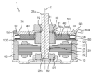
- FIG. 2 is a sectional view of the electric motor according to the embodiment, taken along a plane passing through the rotation axis of the electric motor.
- FIG. 3 is an exploded perspective view of the electric motor according to the embodiment.
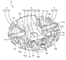
- FIG. 4 is a perspective view of the brush holder in the electric motor according to the embodiment, when the brush holder in which various parts are arranged is viewed from the inner side.
- FIG. 5 is a perspective view of the brush holder in the electric motor according to the embodiment, viewed from the inner side.
- FIG. 6 is a perspective view of the brush holder in the electric motor of the comparative example when viewed from the inner side.
- FIG. 1 is a perspective view of an electric motor according to an embodiment.
- FIG. 2 is a sectional view of the electric motor according to the embodiment, taken along a plane passing through the rotation axis of the electric motor.
- FIG. 3 is an exploded perspective view of the electric motor according to
- FIG. 7 is a plan view of the brush holder viewed from the inner side, for explaining the movement of the pigtail wire when the brush wears and slides in the electric motor using the brush holder of FIG.
- FIG. 8 is an enlarged sectional view of the brush holder and the brush for explaining the movement of the pigtail wire when the brush wears and slides in the electric motor using the brush holder of FIG.
- FIG. 9 is a plan view of the brush holder seen from the inner side, for explaining the movement of the pigtail wire when the brush wears and slides in the electric motor according to the embodiment.
- FIG. 10 is an enlarged sectional view of the brush holder and the brush for explaining the movement of the pigtail wire when the brush wears and slides in the electric motor according to the embodiment.
- FIG. 1 is a perspective view of an electric motor 1 according to an embodiment.
- FIG. 2 is a cross-sectional view of the electric motor 1 taken along a plane passing through the rotating shaft 21 of the electric motor 1 according to the embodiment. In FIG. 2, only the portion that appears in the cross section is illustrated.
- FIG. 3 is an exploded perspective view of the electric motor 1 according to the embodiment.
- FIG. 4 is a perspective view of the brush holder 70 in the electric motor 1 according to the embodiment, in which various parts are arranged, as viewed from the inner side.
- the electric motor 1 is a brushed commutator electric motor. As shown in FIGS. 1 to 4, the electric motor 1 includes a stator 10, a rotor 20, a commutator 30, a brush 40, a pigtail wire 45, a brush spring 50, a frame 60, and a brush holder 70. , a first bearing 81 and a second bearing 82. The electric motor 1 further includes a seal member 90 to ensure the airtightness of the frame 60.
- the electric motor 1 is a direct current motor (DC motor) driven by direct current.
- the electric motor 1 is an in-vehicle motor used in an automobile.
- the electric motor 1 is used in a hydraulic pump for an ABS (Anti-lock Brake System) installed in an automobile.
- ABS Anti-lock Brake System
- the stator 10 (stator) generates magnetic force that acts on the rotor 20 in order to rotate the rotor 20.
- the stator 10 is configured to generate magnetic flux on the air gap surface with the rotor 20.
- the stator 10 constitutes a magnetic circuit together with the rotor 20, which is an armature.
- the stator 10 is configured such that north poles and south poles are alternately present on the air gap surface with the rotor 20 along the circumferential direction of a rotating shaft 21 that the rotor 20 has.
- the stator 10 is a magnetic field that creates magnetic flux for generating torque.
- the stator 10 is composed of a plurality of magnets.
- the magnets constituting the stator 10 are, for example, permanent magnets having an S pole and an N pole.
- the plurality of magnets constituting the stator 10 are arranged so that N poles and S poles are alternately and evenly distributed in the circumferential direction. Therefore, the direction of the main magnetic flux generated by the stator 10 (magnet) is perpendicular to the direction in which the axis C of the rotating shaft 21 extends.
- the plurality of magnets are arranged at equal intervals in the circumferential direction so as to surround the rotor core 22 of the rotor 20.
- each magnet has an arcuate shape with a substantially constant thickness when viewed from above, that is, from the direction in which the axis C extends.
- Each magnet is fixed to the frame 60. Specifically, each magnet is fixed to the inner peripheral surface of the frame 60 with an adhesive, a leaf spring, or the like.
- the rotor 20 (rotor) is rotated by the magnetic force generated in the stator 10.
- the rotor 20 has a rotating shaft 21 .
- the rotor 20 rotates about a rotating shaft 21 as a rotation center.
- the rotor 20 rotates about the axis C of the rotating shaft 21 as the rotation center.
- the rotor 20 is an armature.
- the rotor 20 includes a rotor core 22 and a winding 23 wound around the rotor core 22 .
- the winding 23 is shown schematically.
- the rotating shaft 21 is a shaft that is the center of rotation of the rotor 20.
- the rotating shaft 21 is a metal rod made of a metal material such as stainless steel.
- the rotating shaft 21 extends in the longitudinal direction, which is the direction of the axis C.
- the rotating shaft 21 passes through the rotor core 22.
- the rotating shaft 21 is fixed to a rotor core 22.
- the rotating shaft 21 is fixed to the rotor core 22 while passing through the center of the rotor core 22 so as to extend on both sides of the rotor core 22 .
- the rotating shaft 21 is fixed to the rotor core 22 by press-fitting or shrink-fitting into a center hole formed in the rotor core 22.
- a first portion 21a included in the rotating shaft 21 protrudes from one side of the rotor core 22.
- the first portion 21a is supported by a first bearing 81.
- the first portion 21a of the rotating shaft 21 is an output side portion (output shaft) of the rotating shaft 21.
- the first portion 21 a of the rotating shaft 21 protrudes from the first bearing 81 .
- a load is attached to the first portion 21 a of the rotating shaft 21 at the tip (output side end) of the rotating shaft 21 that protrudes from the first bearing 81 .
- the second portion 21b of the rotating shaft 21 protrudes from the other side of the rotor core 22.
- the second portion 21b of the rotating shaft 21 is supported by a second bearing 82.
- the second portion 21b of the rotating shaft 21 is a portion on the opposite output side of the rotating shaft 21 (non-output shaft).
- the first bearing 81 and the second bearing 82 are bearings that rotatably support the rotating shaft 21.
- the rotating shaft 21 is rotatably supported by the first bearing 81 and the second bearing 82.
- the first bearing 81 is fixed to the brush holder 70.
- the second bearing 82 is fixed to the frame 60.
- the rotor core 22 (rotor core) is an armature core around which the winding 23 is wound.
- the rotor core 22 is a magnetic body made of a magnetic material.
- the rotor core 22 is, for example, a laminate in which a plurality of punched electromagnetic steel sheets formed in a predetermined shape are stacked in the direction of the axis C of the rotating shaft 21.
- the rotor core 22 is not limited to a laminate of electromagnetic steel sheets, but may be a bulk body made of a magnetic material. A minute air gap exists between the outer peripheral surface of the rotor core 22 and the stator 10.
- the rotor core 22 has a plurality of teeth 22a.
- the plurality of teeth 22a are formed radially so as to protrude in the radial direction, which is a direction perpendicular to the axis C of the rotating shaft 21.
- the plurality of teeth 22a are present at equal intervals across the rotational direction of the rotating shaft 21.
- a slot is formed between two adjacent teeth 22a.
- a winding 23 is wound around the rotor core 22.
- the electric wire constituting the winding 23 is, for example, an insulated wire.
- the electric wire constituting the winding 23 includes a conductive wire made of a conductive material such as copper as a core wire, and an insulating film covering the conductive wire.
- the winding 23 is wound around the rotor core 22 via an insulator 24.
- the insulator 24 is made of an insulating resin material or the like.
- the insulator 24 is attached between the winding 23 and the rotor core 22.
- the winding 23 is provided for each slot of the rotor core 22.
- the winding 23 is electrically connected to the commutator 30. Specifically, the winding 23 is electrically connected to the commutator pieces 31 of the commutator 30.
- the rotor 20 When current flows through the winding 23 via the commutator 30, the rotor 20 generates a magnetic force that acts on the stator 10.
- each of the plurality of teeth 22a of the rotor core 22 when a current flows through the winding 23, each of the plurality of teeth 22a of the rotor core 22 generates a magnetic force that acts on the stator 10.
- the main magnetic flux generated by the rotor 20 (teeth 22a) is oriented in the radial direction around the rotating shaft 21.
- the winding 23 is a concentrated winding.
- the winding 23 is wound around each of the plurality of teeth 22a via an insulator 24.
- the rotor 20 is an inner rotor.
- the rotor 20 is arranged inside the stator 10, as shown in FIG. Specifically, the rotor core 22 of the rotor 20 is surrounded by a plurality of magnets forming the stator 10 with a small air gap between the rotor core 22 and the stator 10 .
- a commutator 30 is attached to the rotating shaft 21 of the rotor 20. Therefore, the commutator 30 rotates together with the rotating shaft 21.
- the commutator 30 is attached to a portion of the rotating shaft 21 between the rotor core 22 and the first bearing 81 .
- the commutator 30 has a plurality of commutator pieces 31 (commutator segments).
- the plurality of commutator pieces 31 are arranged in an annular shape at equal intervals so as to surround the rotating shaft 21 .
- the plurality of commutator pieces 31 are conductive terminals made of a metal material such as copper.
- the plurality of commutator pieces 31 are electrically connected to the winding 23 that the rotor 20 has.
- commutator 30 is a molded commutator.
- the commutator 30 has a structure in which a plurality of commutator pieces 31 are molded with resin.
- the plurality of commutator pieces 31 are embedded in a molded resin so that the surfaces thereof are exposed.
- the plurality of commutator pieces 31 are insulated and separated from each other. For example, two adjacent commutator pieces 31 or two commutator pieces 31 located apart are connected by the winding 23.
- a brush 40 is in contact with the commutator 30. Specifically, the brush 40 is in contact with the commutator piece 31 that the commutator 30 has.
- the brush 40 is a power supply brush (current-carrying brush) that supplies power to the winding 23 of the rotor 20.
- a pigtail wire 45 through which current supplied from a power source flows is connected to the brush 40.
- the current (armature current) supplied to the brush 40 via the pigtail wire 45 flows through the commutator piece 31 to the winding 23 of the rotor 20 .
- the current supplied from the power source is supplied to the commutator piece 31 via the pigtail wire 45 and the brush 40.
- the current supplied to the commutator bars 31 is passed through the windings 23 of the rotor 20.
- the brush 40 is a carbon brush made of carbon.
- the brush 40 is a carbon brush containing metal such as copper.
- the brush 40 has an elongated shape in its initial state before being worn out, and is, for example, an elongated substantially rectangular parallelepiped.
- the brush 40 has a front end surface 40a that is a surface in contact with the commutator 30, and a rear end surface 40b that is a surface opposite to the front end surface 40a.
- the front end surface 40a is an end surface at a front end portion that is one end of the brush 40 in the longitudinal direction.
- the rear end surface 40b is an end surface at the rear end portion which is the other end of the brush 40 in the longitudinal direction.
- the front end surface 40a is a sliding surface that comes into sliding contact with the commutator piece 31 of the commutator 30.
- the brush 40 is arranged so that its longitudinal direction is perpendicular to the axis C of the rotating shaft 21 (that is, the radial direction of rotation of the rotating shaft 21).
- a plurality of brushes 40 are arranged. Specifically, two brushes 40 are arranged. In this case, a pair of brushes 40 are provided so as to sandwich the commutator 30 so as to face each other with the commutator 30 in between.
- a front end surface 40a which is an inner tip of each brush 40, is in contact with a commutator piece 31 of the commutator 30. As the electric motor 1 operates to rotate the rotary shaft 21 and the commutator 30 rotates, the front end surface 40a of each brush 40 continues to contact all the commutator pieces 31 in sequence.
- Each brush 40 is arranged so as to be able to come into sliding contact with the commutator 30. As shown in FIG. 2, each brush 40 is constantly in contact with the commutator 30 during operation of the electric motor 1 under pressure from the brush spring 50. Specifically, the front end surface 40a of the brush 40 is always in contact with the commutator piece 31 of the commutator 30. In this way, each brush 40 is pressed against the commutator 30 by the brush spring 50.
- a pigtail wire 45 is connected to the brush 40.
- a first end 45a which is one end of the pigtail wire 45, is connected to the brush 40.
- the first end 45a of the pigtail wire 45 is fixed to the side surface of the brush 40.
- the first end 45a of the pigtail wire 45 is fixed to the brush 40 by being embedded in the side surface of the brush 40.
- the first end 45a of the pigtail wire 45 is connected to the side surface of a portion of the brush 40 that is rearward (closer to the rear end) of the central portion in the longitudinal direction.
- the pigtail wire 45 is an example of a conductive wire. A current supplied from the power terminal 100 flows through the pigtail wire 45 .
- the pigtail line 45 is a power feed line for feeding power to the brush 40. Therefore, when the brush 40 comes into contact with the commutator piece 31, the current (armature current) supplied to the brush 40 via the pigtail wire 45 flows to the winding 23 of the rotor 20 via the commutator piece 31. .
- the second end 45b which is the other end of the pigtail wire 45, is fixed to the choke coil 110.
- the second end 45b of the pigtail wire 45 and the choke coil 110 are fixed by welding such as spot welding.
- the brush spring 50 is an elastic member for pressing the brush 40 against the commutator 30.
- the brush spring 50 is arranged one-to-one with the brush 40. A portion of the brush spring 50 is in contact with the rear end surface 40b of the brush 40.
- the brush spring 50 applies pressure (spring pressure) to the brush 40 using spring elastic force (spring restoring force). Thereby, the brush 40 is urged toward the commutator 30.
- the brush spring 50 is a compression coil spring.
- the brush spring 50 is not limited to a compression coil spring, but may be a torsion spring or the like.
- the brush 40 is stored in a brush storage section 71 provided in the brush holder 70.
- the brush 40 stored in the brush storage section 71 slides within the brush storage section 71 by being pressed by the brush spring 50. Therefore, it is preferable that an appropriate gap (clearance) be provided between the inner surface of the brush accommodating part 71 and the outer surface of the brush 40 so that the brush 40 can slide smoothly in the brush accommodating part 71.
- the brush 40 pressed against the brush spring 50 moves within the brush storage portion 71 toward the commutator 30 as the front end surface 40a of the brush 40 is worn. Specifically, the brush 40 moves in a direction perpendicular to the axis C of the rotating shaft 21, that is, in the radial direction.
- the frame 60 (housing) is a casing (case) that houses the stator 10. That is, the stator 10 is housed in the frame 60.
- the frame 60 also houses the rotor 20. Specifically, the frame 60 houses the rotor core 22 and the windings 23 of the rotor 20.
- the frame 60 is a substantially bottomed cylindrical housing having an opening 60a.
- frame 60 has a substantially cylindrical shape with a bottom.
- the frame 60 is a metal frame made of a metal material such as an iron-based material.
- the frame 60 may be made of a conductive resin material instead of a metal material.
- the frame 60 is also a bracket that holds the second bearing 82. Therefore, the frame 60 is provided with a bearing holding portion 61 that holds the second bearing 82. The second bearing 82 is arranged inside the frame 60.
- the brush holder 70 is a plate-shaped lid disposed to cover the opening 60a of the frame 60. That is, the brush holder 70 covers the opening 60a of the frame 60.
- the opening 60a of the frame 60 has a circular opening shape. Therefore, the top view shape of the brush holder 70 is circular.
- the brush holder 70 is fitted into the opening 60a of the frame 60.
- the brush holder 70 is press-fitted into the open end of the frame 60. Thereby, the brush holder 70 is fixed to the open end of the frame 60. Therefore, the side surface of the outer peripheral end of the brush holder 70 is in contact with the inner surface of the open end of the frame 60.
- the frame 60 and the brush holder 70 constitute an outer casing of the electric motor 1.
- the outer casing composed of the frame 60 and the brush holder 70 houses not only the stator 10 and the rotor 20 but also other parts constituting the electric motor 1 such as the commutator 30 and the brushes 40.
- the brush holder 70 is a holding member that holds the brush 40.
- the brush holder 70 has a brush storage section 71 as a brush holding section in order to hold the brush 40.
- the brush holder 70 is also a bracket that holds the first bearing 81.
- the first bearing 81 is fixed to the brush holder 70. As shown in FIGS. 1 and 2, the first bearing 81 is arranged and fixed on the outer surface of the brush holder 70. As shown in FIGS. 1 and 2, the first bearing 81 is arranged and fixed on the outer surface of the brush holder 70. As shown in FIGS.
- a recess 70a is formed on the outer surface of the brush holder 70.
- the recess 70a is a reservoir tank for temporarily storing liquid such as oil leaked from mechanical parts etc. around the electric motor 1.
- the recess 70a is formed to protrude inward so as to recess a portion of the outer surface.
- a stepped portion 70b on which the seal member 90 is placed is formed on the outer surface of the brush holder 70.
- the stepped portion 70b is formed in the shape of a collar at the outer peripheral end of the brush holder 70.
- the stepped portion 70b is formed in an annular shape over the entire circumference of the brush holder 70.
- the stepped portion 70b is formed by reducing the thickness of the outer peripheral end of the brush holder 70.
- the seal member 90 is held between the rising surface of the stepped portion 70b and the inner surface of the frame 60. Specifically, the seal member 90 is fixed to the stepped portion 70b by being press-fitted into the stepped portion 70b.
- the seal member 90 placed on the stepped portion 70b is an annular seal ring for ensuring airtightness between the frame 60 and the brush holder 70.
- the seal member 90 is in contact with the inner surface of the frame 60.
- the seal member 90 has an annular shape.
- the seal member 90 has rubber elasticity.
- the seal member 90 is made of a resin material such as an elastomer, or an elastic material.
- the brush holder 70 is made of resin material. That is, the brush holder 70 is a resin plate made of resin. As an example, the brush holder 70 is made of polyphthalamide (PPA), nylon 6, or the like. The brush holder 70 is a resin molded product integrally made of a resin material.
- a pair of power supply terminals 100 and a choke coil 110 are arranged on the inner surface (inner surface) of the brush holder 70.
- the pair of power terminals 100 are arranged in a terminal arrangement part 70c provided in the brush holder 70.
- the terminal placement portion 70c is, for example, a recess provided in a protrusion that protrudes from the inner surface of the brush holder 70.
- Each of the pair of power supply terminals 100 is fixed to the brush holder 70 by being inserted into the terminal arrangement portion 70c, for example.
- the pair of choke coils 110 are arranged in a coil arrangement section 70d provided in the brush holder 70.
- Each of the pair of choke coils 110 is fixed to the brush holder 70, for example, by a locking claw provided on the inner surface of the brush holder 70.
- the coil placement portion 70d is, for example, a recessed portion formed by recessing the inner surface of the brush holder 70.
- the pair of power supply terminals 100 are power supply terminals for supplying power from an external power supply.
- One of the pair of power supply terminals 100 is a positive power supply terminal connected to the positive side of the DC power supply.
- the other of the pair of power supply terminals 100 is a negative power supply terminal connected to the negative pole side of the DC power supply.
- the choke coil 110 is inserted into the current path between the brush 40 and the power supply terminal 100. Thereby, noise contained in the current flowing in the current path between the brush 40 and the power supply terminal 100 can be removed.
- the choke coil 110 is arranged in one-to-one correspondence with the brush 40.
- two choke coils 110 are arranged.
- One of the two choke coils 110 is inserted into a current path between one of the two brushes 40 and one of the pair of power terminals 100.
- the other of the two choke coils 110 is inserted into a current path between the other of the two brushes 40 and the other of the pair of power terminals 100.
- each choke coil 110 one end of the choke coil 110 is fixed to the second end 45b of the pigtail wire 45. As described above, one end of the choke coil 110 and the second end 45b of the pigtail wire 45 are connected and fixed by welding or the like.
- the coil wire material of the choke coil 110 is hard. Therefore, the tip of the choke coil 110 is not in contact with the brush holder 70 and is floating above the inner surface of the brush holder 70. Therefore, the connection portion CP (welded portion) where one end of the choke coil 110 and the second end 45b of the pigtail wire 45 are connected does not contact the brush holder 70, and the connection portion A gap exists between the CP and the brush holder 70. There may be no gap between the connection portion CP and the brush holder 70. That is, the connecting portion CP may be in contact with the brush holder 70.
- each choke coil 110 the other end of the choke coil 110 is electrically connected to the power supply terminal 100 via a conductive member.
- the other end of choke coil 110 and power supply terminal 100 may be directly connected.
- the current supplied to the brushes 40 via the power supply terminal 100 flows as an armature current (driving current) to the winding 23 of the rotor 20 via the commutator 30. .
- magnetic flux is generated in the rotor 20.
- the magnetic force generated by the interaction between the magnetic flux generated in the rotor 20 and the magnetic flux generated from the stator 10 becomes a torque that rotates the rotor 20.
- the direction in which the current flows is switched depending on the positional relationship when the commutator piece 31 and the brush 40 are in contact with each other.
- FIG. 5 is a perspective view of the brush holder 70 in the electric motor 1 according to the embodiment, viewed from the inner side.
- FIG. 5 is a diagram in which various parts arranged in the brush holder 70 are omitted from FIG. 4. In FIG. 5, only the brush holder 70 is illustrated.
- various uneven structures are integrally formed on the inner surface of the resin brush holder 70.
- Various parts are arranged on the inner surface of the brush holder 70. These parts are held in a brush holder 70. Specifically, on the inner surface of the brush holder 70, a brush 40, a pigtail wire 45, a power terminal 100, a choke coil 110, a cover plate 120, and the like are arranged.
- the brush holder 70 has a brush storage section 71 that stores the brush 40.
- the brush storage section 71 is a part of the brush holder 70.
- the brush storage section 71 is provided on the inner surface of the brush holder 70.
- a brush storage section 71 is provided for each brush 40.
- two brushes 40 are used.
- the brush holder 70 is provided with two brush storage sections 71.
- a brush opening 71a for exposing the front end surface 40a of the brush 40 is provided on the commutator 30 side (rotating shaft 21 side) of each brush storage section 71.
- the brush 40 stored in the brush storage portion 71 comes into contact with the commutator piece 31 of the commutator 30 by protruding from the brush opening 71a.
- Each brush storage section 71 is constructed by forming the brush holder 70 into a concave shape.
- Each brush storage section 71 has an elongated shape whose longitudinal direction is the direction in which the brush 40 moves.
- Each brush storage portion 71 is elongated in a direction perpendicular to the axis C of the rotating shaft 21 (that is, in the radial direction of the rotating shaft 21).
- each brush storage portion 71 is formed to have a concave cross-sectional shape.
- each brush storage section 71 has a first side wall 711 and a second side wall 712 as a pair of side walls sandwiching the brush 40 therebetween.
- a pigtail wire 45 is connected to the side of the brush 40. Therefore, one of the first side wall 711 and the second side wall 712 has a portion lower in height than the other.
- the first side wall 711 has a low back portion 713 as a portion lower in height than the second side wall 712.
- the pigtail wire 45 passes over the low back portion 713 of the first side wall 711 and is pulled out from the side of the brush storage portion 71 .
- the low profile portion 713 of the first side wall 711 extends to the brush opening 71a.
- the pigtail wire 45 pulled out from the side of the brush storage portion 71 passes over the low-back portion 713 of the first side wall 711 as the brush 40 is worn and the brush 40 slides toward the commutator 30. It will move closer to the commutator 30 side.
- a stepped portion 714 is provided on the outer side surface of the first side wall 711 of the first side wall 711 and the second side wall 712.
- the stepped portion 714 is formed in a step-like shape.
- the step portion 714 is formed in only one step.
- the step portion 714 has a step surface 714 a that is one step lower than the top surface of the low back portion 713 of the first side wall 711 .
- the step portion 714 may be configured with multiple steps.
- the brush storage section 71 is covered by a cover plate 120. That is, the cover plate 120 covers the brush 40.
- the cover plate 120 is, for example, a metal cover made of a metal plate.
- the cover plate 120 is arranged to cover the brush storage section 71.
- the cover plate 120 is provided with a locking claw. By press-fitting this locking pawl into a locking hole formed in the brush holder 70, the cover plate 120 can be fixed to the brush holder 70.
- the locking holes are formed in the first side wall 711 and the second side wall 712, for example.
- the brush 40 stored in the brush storage section 71 is surrounded on four sides by the brush storage section 71 and the cover plate 120. That is, the brush storage portion 71 and the cover plate 120 constitute a substantially rectangular cylindrical brush box (brush box) that stores the brushes 40. Since the first side wall 711 constituting the brush storage section 71 has the low height section 713, a part of the side surface of the brush box formed of the brush storage section 71 and the cover plate 120 is open. A pigtail wire 45 connected to the brush 40 is pulled out from an opening provided on the side of the brush box.
- each brush storage section 71 stores a brush spring 50 together with the brush 40. Therefore, the length of the brush storage section 71 in the longitudinal direction is longer than the length of the brush 40.
- the brush spring 50 is held between the rear end surface 40b of the brush 40 and the rear end portion of the brush storage portion 71.
- the cover plate 120 covers not only the brush 40 but also the brush spring 50.
- the brush holder 70 covers the opening 60a of the frame 60. Therefore, the brush holder 70 covers the rotor 20 housed in the frame 60. Specifically, as shown in FIG. 2, the brush holder 70 covers the rotor core 22 to which the rotating shaft 21 is fixed. For this reason, as shown in FIGS. 3 to 5, the brush holder 70 is provided with a through hole 72 through which the rotating shaft 21 passes.
- the through hole 72 is provided in the center of the brush holder 70.
- the opening shape of the through hole 72 is circular. The center of the through hole 72 coincides with the axis C of the rotating shaft 21.
- the brush holder 70 has an annular wall 73 surrounding the through hole 72.
- the annular wall 73 is formed on the inner surface of the brush holder 70 so as to protrude from the opening edge of the through hole 72 .
- the annular wall 73 has portions with different heights. Specifically, the annular wall 73 includes a first wall portion 731 and a second wall portion 732 having a lower height than the first wall portion 731. Two first wall portions 731 and two second wall portions 732 are provided. One of the two first wall portions 731 (the first wall portion 731 on the power terminal 100 side) is sandwiched between the two second wall portions 732. The other of the two first wall portions 731 is a part of the inner side wall of the recess 70a serving as a reservoir tank.
- the second wall portion 732 is formed continuously with a step portion 714 formed on the first side wall 711 that constitutes the brush storage portion 71.
- the second wall portion 732 and the stepped portion 714 are integrally formed.
- the upper surface of the second wall portion 732 and the stepped surface 714a of the stepped portion 714 are flush with each other.
- the height of the second wall portion 732 and the height of the stepped surface 714a of the stepped portion 714 are the same.
- the annular wall 73 further includes a third wall portion 733.
- the height of the third wall portion 733 is lower than the height of the first wall portion 731.
- the height of the third wall portion 733 is higher than the height of the second wall portion 732.
- the third wall portion 733 is formed continuously with the second side wall 712 that constitutes the brush storage portion 71 .
- the front part of the brush storage section 71 is connected to an annular wall 73.
- the brush storage portion 71 and the annular wall 73 are integrally formed.
- the annular wall 73 is provided with a brush opening 71a of the brush storage section 71.
- the brush opening 71a is provided in the third wall 733.
- the second wall portion 732 having the lowest height is provided near the brush opening 71a.
- the brush holder 70 has ribs 74.
- the rib 74 is formed on the inner surface of the brush holder 70.
- the rib 74 is formed in a convex shape so as to protrude from the inner surface of the brush holder 70.
- the rib 74 is formed in an elongated shape. Rib 74 extends outward from through hole 72 .
- the rib 74 is formed in a straight line.
- the rib 74 extends in a direction perpendicular to the rotating shaft 21 (that is, in the radial direction).
- each of the two ribs 74 extends from near the center of the corresponding one of the two choke coils 110 toward the center of the through hole 72 (the axis C of the rotating shaft 21). .
- Each rib 74 has a rectangular cross-sectional shape in a plane perpendicular to the longitudinal direction. Therefore, the upper surface of each rib 74 is a flat surface.
- the number of ribs 74 is not limited to two, and may be one or three or more.
- the plurality of ribs 74 are formed radially around the through hole 72 .
- Each rib 74 has an inclined portion 741 whose upper surface is inclined. Specifically, the inclined portion 741 has an inclined surface 741a whose height gradually increases toward the through hole 72 (rotary shaft 21).
- Each rib 74 is connected to the second wall portion 732 of the annular wall 73.
- the inclined portion 741 of the rib 74 is formed in a portion of the rib 74 on the through hole 72 side.
- the inclined portion 741 of the rib 74 is formed continuously with the second wall portion 732 of the annular wall 73. That is, the inclined portion 741 and the second wall portion 732 are integrally formed.
- the sloped surface 741a of the sloped portion 741 is sloped so that its height increases toward the upper surface of the second wall portion 732.
- the maximum height of the inclined surface 741a of the inclined part 741 and the height of the second wall part 732 are the same.
- a connecting portion CP where the second end 45b of the pigtail wire 45 and the choke coil 110 are connected is located above the rib 74.
- the connecting portion CP is located outside the inclined portion 741 when viewed from above.
- the rib 74 and the connecting portion CP are not in contact with each other. In other words, a slight gap exists between the connecting portion CP and the rib 74.
- the connecting portion CP is separated from the upper surface of the rib 74.
- the connecting portion CP does not need to be located above the rib 74. That is, the connecting portion CP may be located above the inner surface of the brush holder 70 other than the rib 74. There may be no gap between the connecting portion CP and the rib 74. That is, the connecting portion CP may be in contact with the rib 74.
- the thickness of the plate-shaped base portion (plate) of the brush holder 70 is thin. Therefore, the ribs 74 also function as reinforcing ribs to improve the strength of the brush holder 70. In other words, it can be said that the ribs 74 are formed as a result of partially recessing the inner surface of the brush holder 70 in order to reduce the thickness of the base portion of the brush holder 70.
- a guide part (pigtail line guide part) is provided on the inner surface of the brush holder 70 to guide the pigtail line 45 when the pigtail line 45 moves as the brush 40 wears.
- the pigtail wire guide section is for keeping the pigtail wire 45, which moves as the brush 40 slides due to wear of the brush 40, in a constant motion. Specifically, the pigtail wire guide section allows the pigtail wire 45 to move smoothly.
- the brush holder 70 has an inclined portion 741 formed on the rib 74 as a first guide portion which is one of the pigtail wire guide portions.
- the brush holder 70 has a stepped portion 714 formed on the first side wall 711 constituting the brush storage portion 71 as a second guide portion that is one of the pigtail wire guide portions.
- the brush holder 70 has a second wall portion 732 formed on the annular wall 73 as a third guide portion that is one of the pigtail wire guide portions.
- FIG. 6 is a perspective view of the brush holder 70X in the electric motor of the comparative example when viewed from the inner side.
- FIG. 7 is a plan view of the brush holder 70X seen from the inner side, for explaining the movement of the pigtail wire 45 when the brush 40 wears and slides in the electric motor using the brush holder 70X of FIG. It is.
- FIG. 8 is an enlarged sectional view of the brush holder 70X and the brush 40 for explaining the movement of the pigtail wire 45 when the brush wears and slides in the electric motor using the brush holder 70X of FIG.
- FIG. 9 is a plan view of the brush holder 70 viewed from the inner side, for explaining the movement of the pigtail wire 45 when the brush 40 wears and slides in the electric motor 1 according to the embodiment.
- FIG. 10 is an enlarged sectional view of the brush holder 70 and the brush 40 for explaining the movement of the pigtail wire 45 when the brush 40 wears and slides in the electric motor 1 according to the embodiment.
- the brush 40, pigtail wire 45, brush spring 50, power terminal 100, and choke coil 110 are arranged similarly to the brush holder 70 of the present embodiment. ing. One end of the pigtail wire 45 is connected to the side surface of the brush 40. The other end of the pigtail wire 45 is connected to and fixed to the choke coil 110.
- the brush holder 70X of the comparative example has a brush storage section 71X that stores the brush 40, similar to the brush holder 70 of the present embodiment.
- the brush storage section 71X that the brush holder 70X of the comparative example has is different from the brush storage section 71 that the brush holder 70 of the present embodiment has.
- the step portion 714 is not formed in the first side wall 711X that constitutes the brush storage portion 71X of the brush holder 70X of the comparative example.
- the first side wall 711X has a low-back part 713 as a part lower in height than the second side wall 712, similar to the brush storage part 71 in the present embodiment. . Therefore, also in the brush holder 70X of the comparative example, the pigtail wire 45 connected to the side surface of the brush 40 is drawn out passing over the low back portion 713.
- the brush holder 70X of the comparative example has an annular wall 73X similarly to the brush holder 70 of the present embodiment.
- the annular wall 73X that the brush holder 70X of the comparative example has is different from the annular wall 73 that the brush holder 70 of the present embodiment has.
- the second wall portion 732 is not formed in the annular wall 73X of the brush holder 70X of the comparative example.
- the annular wall 73X of the brush holder 70X of the comparative example has only the first wall portion 731 and the third wall portion 733 provided in the annular wall 73 of the brush holder 70 of the present embodiment. ing.
- a rib 74 is formed in the brush holder 70 in this embodiment, a structure corresponding to the rib 74 is not formed in the brush holder 70X of the comparative example.
- the rear end surface of the brush 40 approaches the commutator (rotation shaft).
- the pigtail wire 45 connected to the brush 40 is pulled by the brush 40 and moves toward the commutator side (inside).
- the pigtail wire 45 moves toward the commutator side, with the connecting portion CP where the pigtail wire 45 and the choke coil 110 are connected as a fixed end.
- the length of the pigtail wire 45 itself does not change. Therefore, the shape changes as it moves toward the commutator.
- a part or the whole of the pigtail wire 45 may be curved so as to be convex inward (commutator side), or conversely, curved so as to be convex outward. I do things.
- part or all of the pigtail line 45 may be curved so as to be convex upward in the thickness direction of the brush holder 70X, or may be convex downward in the thickness direction of the brush holder 70X. It can also be curved.
- the pigtail wire 45 is a mesh wire or a twisted wire. Therefore, as shown in FIGS. 7 and 8, not only the shape changes as the object moves, but also the thickness may change. For example, the pigtail line 45 may partially become thicker as it moves.
- an uneven structure such as the brush storage portion 71X and the annular wall 73X is formed on the inner surface of the brush holder 70X.
- the pigtail wire 45 moves toward the commutator side while changing its shape and thickness as the brush 40 wears, the pigtail wire 45 changes to the uneven structure of the brush holder 70X.
- the pigtail wire 45 and the uneven structure of the brush holder 70X may interfere with each other due to, for example, being caught in the brush holder 70X.
- the pigtail wire 45 may contact the wall surface of the first side wall 711X that constitutes the brush storage portion 71X, the choke coil 110, the annular wall 73X at the end of the wear of the brush 40, or other Otherwise, the brush holder 70X may hit the uneven structure formed on the brush holder 70X and interfere with the brush holder 70X.
- the brush holder 70 is provided with one or more guide portions that guide the pigtail wire 45 when the pigtail wire 45 moves as the brush 40 wears out. There is.
- the brush 40 is worn out from the state before the brush 40 wears out as shown in FIG. 9(a), and the pigtail wire 45 and the choke coil 110 are connected as shown in FIG. 9(b).
- the pigtail wire 45 moves toward the commutator side with the connected portion CP fixed as the fixed end, the pigtail wire 45 is guided by a guide portion provided on the brush holder 70 and moves in a constant motion. It will continue to transform.
- a first guide portion which is one of the guide portions, is provided on the rib 74.
- the first guide portion provided on the rib 74 is an inclined portion 741 having an inclined surface 741a whose height gradually increases toward the through hole 72.
- the connecting portion CP where the pigtail wire 45 and the choke coil 110 are connected is located above the rib 74 on the outside of the inclined portion 741 .
- the pigtail wire 45 is It is guided along the inclined surface 741a of the inclined portion 741 (first guide portion), which is the upper surface of the rib 74, and moves in a constant motion without being caught. That is, the inclined surface 741a of the inclined portion 741 is a guide surface that guides the pigtail wire 45.
- the rib 74 and the second wall portion 732 of the annular wall 73 are formed continuously.
- the maximum height of the inclined surface 741a of the inclined portion 741 is the same as the height of the second wall portion 732 of the annular wall 73.
- the pigtail wire 45 that is guided along the inclined surface 741a of the inclined portion 741 and moves toward the commutator side continues to move to the upper surface of the second wall portion 732 even beyond the inclined surface 741a. This can prevent the pigtail wire 45 from getting caught on the annular wall 73.
- a second guide portion which is another one of the guide portions, is provided in the brush storage portion 71.
- the second guide section provided in the brush storage section 71 is provided on the first side wall 711 of a pair of first side walls 711 and second side walls 712 that constitute the brush storage section 71 .
- the second guide portion provided on the first side wall 711 is a stepped portion 714 provided on the outer side surface of the first side wall 711.
- first side wall 711 and the second wall portion 732 are formed continuously.
- the height of the stepped surface 714a of the stepped portion 714 formed on the first side wall 711 is the same as the height of the second wall portion 732 of the annular wall 73.
- the pigtail wire 45 that is guided and moves along the stepped portion 714 of the first side wall 711 continues to move to the upper surface of the second wall portion 732 even beyond the stepped portion 714. Therefore, the pigtail wire 45 can be prevented from getting caught on the annular wall 73.
- a third guide portion which is another one of the guide portions, is provided on the annular wall 73.
- the third guide portion provided on the annular wall 73 is the second wall portion 732 located near the brush opening 71a of the brush storage portion 71.
- the shape and thickness of the pigtail wire 45 change and a portion of the pigtail wire 45 temporarily reaches the annular wall 73.
- the pigtail wire 45 is guided by the second wall portion 732 (third guide portion) of the annular wall 73. Therefore, it is possible to suppress the pigtail wire 45 from hitting or getting caught on the tall first wall portion 731. Thereby, interference of the pigtail wire 45 with the annular wall 73 can be suppressed.
- the pigtail wire 45 moves toward the commutator 30 side as the brush 40 wears, the pigtail wire 45 is moved to the one or more guide portions (the first guide part, second guide part, and third guide part).
- the pigtail wire 45 moves toward the commutator while maintaining a constant shape. Therefore, interference between the pigtail wire 45 and the uneven structure of the brush holder 70 can be suppressed. As a result, the pressure applied by the brush 40 to the commutator 30 can be suppressed from decreasing. Therefore, it is possible to suppress the occurrence of conduction failure between the brush 40 and the commutator 30. Therefore, the pressure applied to the commutator 30 by the brush 40 is reduced, and it is possible to prevent the life of the electric motor 1 from being shortened.
- the electric motor 1 includes a rotor 20 having a rotating shaft 21 extending in the axial direction, a commutator 30 attached to the rotating shaft 21, and a brush 40 in contact with the commutator 30. , a brush holder 70 having a through hole 72 through which the rotating shaft 21 passes and a brush storage section 71 that stores the brush 40, and a conductive wire corresponding to the pigtail wire 45 whose one end is connected to the brush 40.
- the brush holder 70 is provided with one or more guide portions that guide the conductive wire as it moves as the brush 40 wears.
- a pigtail wire is exemplified as the conductive wire connected to the brush 40.
- the conductive wire connected to the brush 40 is not limited to a pigtail wire.
- the conductive wire connected to the brush 40 may be an electric wire such as a vinyl wire.
- the thickness of the pigtail wire tends to change easily. Therefore, if a pigtail wire is used as the conductive wire connected to the brush 40, the effect of the guide portion according to the present disclosure is greater.
- the electric motor 1 in the above embodiment includes a choke coil 110. However, it is not limited to this. That is, the electric motor 1 does not need to have the choke coil 110.
- the second end 45b of the pigtail wire 45 may be directly connected to the power terminal 100, or may be connected to another conductive component connected to the power terminal 100. In either case, when the pigtail wire 45 moves toward the commutator side due to wear of the brush 40, the second end 45b of the pigtail wire 45 becomes a fixed end.
- the stator 10 is composed of a magnet. However, it is not limited to this.
- the stator 10 may include a stator core and a winding wound around the stator core.
- the electric motor 1 in the embodiment described above can be used not only for electrical equipment mounted on a car but also for various electrical equipment.
- the electric motor 1 may be used in household electrical equipment, industrial equipment, power tools, and the like.
- the electric motor according to the present disclosure can be used in various products equipped with the electric motor, including automobiles and the like.
Landscapes
- Engineering & Computer Science (AREA)
- Power Engineering (AREA)
- Motor Or Generator Current Collectors (AREA)
Abstract
軸心方向に延伸する回転軸を有する回転子と、回転軸に取り付けられた整流子と、整流子に接するブラシと、回転軸が貫通する貫通孔及びブラシを収納するブラシ収納部を有するブラシホルダと、一方の端部がブラシに接続された導電線と、を備え、ブラシホルダには、ブラシが摩耗するにしたがって導電線が移動する際に導電線をガイドするガイド部が1つ以上設けられている。
Description
本開示は、電動機に関する。
電動機は、電気掃除機等の家庭用機器、半導体製造装置等の産業用機器及び自動車等の車両等、様々な製品に用いられている。例えば、電気掃除機に搭載される電動送風機には、回転ファンを回転させるために電動機が用いられている。二輪又は四輪の自動車には、ESC(Electronic Stability Control)等に電動機が用いられている。
電動機としては、ブラシを用いる整流子電動機、及び、ブラシを用いないブラシレス電動機が知られている。このうち、整流子電動機は、固定子と、固定子の磁力によって回転する回転子と、回転子の回転軸に取り付けられた整流子と、整流子に接するブラシとを備える。
整流子電動機において、ブラシは、ブラシ収納部に収納されている。従来、回転子及び固定子を収納する筐体の開口部を覆うブラシホルダの内面にブラシ収納部が設けられた整流子電動機が提案されている(特許文献1を参照)。
整流子電動機が有するブラシには、ピグテール線が接続されている。例えば、ピグテール線は、一方の端部がブラシの側面に固定され、他方の端部が電源端子及びチョークコイル等の電子部品に固定されている。
ブラシに接続されたピグテール線は、ブラシの摩耗によるブラシの摺動に伴って移動する。このとき、ピグテール線は、移動するにつれて、形状が変化する。特に、ピグテール線は、網線又は撚り線である。このため、ピグテール線は、移動するにつれて、形状が変化するだけではなく、太さも変化する。
筐体の開口部を覆うプレート状のブラシホルダを備える電動機では、ピグテール線は、ブラシとともにブラシホルダに配置される。この場合、ブラシホルダには、ブラシ収納部等の大小様々な凹凸構造が形成されている。
このようなブラシホルダに配置されたピグテール線は、電動機が動作してブラシが摩耗するにつれて整流子側に移動する。このとき、ピグテール線は、形状や太さが変化しながら移動すると、ブラシホルダの凹凸構造に干渉することがある。この結果、ブラシによる整流子への押し圧が減少することがある。
このように、電動機は、ブラシによる整流子への押し圧が減少すると、ブラシの有効摩耗部が残っているにもかかわらず、ブラシと整流子との導通不良等が発生し、電動機としての機能を失ってしまうことがある。つまり、電動機の寿命が短くなる。
本開示は、このような問題を解決するためになされたものである。本開示は、寿命の低下を抑制することができる電動機を提供することを目的とする。
上記目的を達成するために、本開示に係る電動機の一態様は、軸心方向に延伸する回転軸を有する回転子と、前記回転軸に取り付けられた整流子と、前記整流子に接するブラシと、前記回転軸が貫通する貫通孔及び前記ブラシを収納するブラシ収納部を有するブラシホルダと、一方の端部が前記ブラシに接続された導電線と、を備え、前記ブラシホルダには、前記ブラシが摩耗するにしたがって前記導電線が移動する際に前記導電線をガイドするガイド部が1つ以上設けられている。
本開示によれば、ブラシによる整流子への押し圧が減少することを抑制できる。したがって、電動機の寿命が低下することを抑制できる。
以下、本開示の実施の形態について、図面を参照しながら説明する。以下に説明する実施の形態は、いずれも本開示の一具体例を示すものである。したがって、以下の実施の形態で示される、数値、構成要素、構成要素の配置位置及び接続形態、並びに、工程及び工程の順序等は、一例であって本開示を限定する主旨ではない。よって、以下の実施の形態における構成要素のうち、本開示の最上位概念を示す独立請求項に記載されていない構成要素については、任意の構成要素として説明される。
各図は、模式図であり、必ずしも厳密に図示されたものではない。各図において、実質的に他の図と同一の構成に対しては同一の符号を付しており、重複する説明は省略又は簡略化する。本明細書において、「上」及び「下」という用語は、必ずしも、絶対的な空間認識における上方向(鉛直上方)及び下方向(鉛直下方)を指すものではない。
(実施の形態)
まず、実施の形態に係る電動機1の構成について、図1~図4を用いて説明する。図1は、実施の形態に係る電動機1の斜視図である。図2は、実施の形態に係る電動機1の回転軸21を通る平面で切断したときの電動機1の断面図である。図2では、断面に表れる部分のみを図示している。図3は、実施の形態に係る電動機1の分解斜視図である。図4は、実施の形態に係る電動機1におけるブラシホルダ70において、各種部品が配置されたブラシホルダ70を内面側から見たときの斜視図である。
まず、実施の形態に係る電動機1の構成について、図1~図4を用いて説明する。図1は、実施の形態に係る電動機1の斜視図である。図2は、実施の形態に係る電動機1の回転軸21を通る平面で切断したときの電動機1の断面図である。図2では、断面に表れる部分のみを図示している。図3は、実施の形態に係る電動機1の分解斜視図である。図4は、実施の形態に係る電動機1におけるブラシホルダ70において、各種部品が配置されたブラシホルダ70を内面側から見たときの斜視図である。
電動機1は、ブラシ付きの整流子電動機である。電動機1は、図1~図4に示すように、固定子10と、回転子20と、整流子30と、ブラシ40と、ピグテール線45と、ブラシバネ50と、フレーム60と、ブラシホルダ70と、第1軸受81及び第2軸受82と、を備える。電動機1は、フレーム60の気密性を確保するために、さらに、シール部材90を備える。
電動機1は、直流により駆動する直流電動機(DCモータ)である。一例として、電動機1は、自動車に用いられる車載用モータである。例えば、電動機1は、自動車に搭載されるABS(Anti-lock Brake System)の油圧ポンプに用いられる。以下、電動機1の各構成部材について詳細に説明する。
固定子10(ステータ)は、回転子20を回転させるために回転子20に作用する磁力を発生させる。固定子10は、回転子20とのエアギャップ面に磁束を生成する構成になっている。固定子10は、電機子である回転子20とともに磁気回路を構成している。固定子10は、回転子20が有する回転軸21の周方向に沿って、回転子20とのエアギャップ面にN極とS極とが交互に存在するように、構成されている。固定子10は、トルクを発生するための磁束を作る界磁である。固定子10は、複数の磁石(マグネット)によって構成されている。固定子10を構成する磁石は、例えばS極及びN極を有する永久磁石である。
固定子10を構成する複数の磁石は、周方向においてN極とS極とが交互に均等に存在するように配置されている。したがって、固定子10(磁石)が発生する主磁束の向きは、回転軸21の軸心Cが延伸する方向と直交する方向である。複数の磁石は、回転子20の回転子鉄心22を囲むようにして周方向において等間隔で配置されている。一例として、各磁石は、上面視、すなわち軸心Cが延伸する方向から見て厚さが実質的に一定の円弧形状である。各磁石は、フレーム60に固定されている。具体的には、各磁石は、フレーム60の内周面に接着剤、あるいは板バネなどにより固定されている。
回転子20(ロータ)は、固定子10に生じる磁力によって回転する。回転子20は、回転軸21を有している。回転子20は、回転軸21を回転中心として回転する。具体的には、回転子20は、回転軸21の軸心Cを回転中心として回転する。
回転子20は、電機子である。回転子20は、回転子鉄心22と、回転子鉄心22に巻き回された巻線23とを備える。図2において、巻線23は、模式的に示されている。
回転軸21は、回転子20が回転する際の中心となるシャフトである。一例として、回転軸21は、ステンレス等の金属材料によって構成された金属棒である。回転軸21は、軸心C方向である長手方向に延伸している。
回転軸21は、回転子鉄心22を貫通している。回転軸21は、回転子鉄心22に固定されている。具体的には、回転軸21は、回転子鉄心22の両側に延在するように回転子鉄心22の中心を貫いた状態で、回転子鉄心22に固定されている。回転軸21は、回転子鉄心22に形成された中心孔に圧入したり、焼き嵌めしたりすることで、回転子鉄心22に固定されている。
回転軸21が含む第1部位21aは、回転子鉄心22の一方側から突出している。第1部位21aは、第1軸受81に支持されている。回転軸21の第1部位21aは、回転軸21の出力側の部位(出力軸)である。具体的には、回転軸21の第1部位21aは、第1軸受81から突出している。回転軸21の第1部位21aは、第1軸受81から突出した回転軸21の先端部(出力側の端部)に、負荷が取り付けられる。
一方、回転軸21の第2部位21bは、回転子鉄心22の他方から突出している。回転軸21の第2部位21bは、第2軸受82に支持されている。回転軸21の第2部位21bは、回転軸21の反出力側の部位(反出力軸)である。
一例として、第1軸受81及び第2軸受82は、回転軸21を回転自在に支持するベアリングである。このように、回転軸21は、回転自在な状態で第1軸受81と第2軸受82とに支持されている。なお、第1軸受81は、ブラシホルダ70に固定されている。第2軸受82は、フレーム60に固定されている。
回転子鉄心22(ロータコア)は、巻線23が巻回される電機子コアである。回転子鉄心22は、磁性材料によって構成された磁性体である。回転子鉄心22は、例えば、所定形状に形成された複数の打ち抜き電磁鋼板が回転軸21の軸心C方向に積層された積層体である。回転子鉄心22は、電磁鋼板の積層体に限るものではなく、磁性材料によって構成されたバルク体であってもよい。回転子鉄心22の外周面と固定子10との間には微小なエアギャップが存在する。
図3に示すように、回転子鉄心22は、複数のティース22aを有する。複数のティース22aは、回転軸21の軸心Cと直交する方向である径方向(ラジアル方向)に突出するように、放射状に形成されている。複数のティース22aは、回転軸21の回転方向にわたって等間隔に存在している。隣り合う2つのティース22aの間には、スロットが形成されている。
図2及び図3に示すように、回転子鉄心22には、巻線23が巻き回されている。巻線23を構成する電線は、例えば絶縁被覆線である。巻線23を構成する電線は、芯線となる銅等の導電材料からなる導電線と、この導電線を被膜する絶縁膜とを有する。
巻線23は、インシュレータ24を介して、回転子鉄心22に巻回されている。インシュレータ24は、絶縁樹脂材料等によって構成されている。インシュレータ24は、巻線23と回転子鉄心22との間に取り付けられている。巻線23は、回転子鉄心22のスロットごとに設けられている。
巻線23は、整流子30と電気的に接続されている。具体的には、巻線23は、整流子30が有する整流子片31と電気的に接続されている。整流子30を介して巻線23に電流が流れることで、回転子20は、固定子10に作用させる磁力を発生させる。具体的には、巻線23に電流が流れることで、回転子鉄心22が有する複数のティース22aの各々が固定子10に作用させる磁力を発生させる。回転子20(ティース22a)が発生する主磁束の向きは、回転軸21を中心とする径方向である。巻線23は、集中巻きである。巻線23は、インシュレータ24を介して、複数のティース22aの各々に巻回されている。
回転子20は、インナーロータである。回転子20は、図2に示すように、固定子10の内側に配置されている。具体的には、回転子20の回転子鉄心22は、固定子10との間に微小なエアギャップを介して、固定子10を構成する複数の磁石に囲まれている。
回転子20の回転軸21には、整流子30が取り付けられている。したがって、整流子30は、回転軸21とともに回転する。整流子30は、回転軸21における回転子鉄心22と第1軸受81との間の部位に取り付けられている。
図2及び図3に示すように、整流子30は、複数の整流子片31(整流子セグメント)を有する。複数の整流子片31は、回転軸21を囲むように、円環状に等間隔で配列されている。複数の整流子片31は、例えば銅等の金属材料によって構成された導電端子である。複数の整流子片31は、回転子20が有する巻線23と電気的に接続されている。一例として、整流子30は、モールド整流子である。整流子30は、複数の整流子片31が樹脂モールドされた構成になっている。複数の整流子片31は、表面が露出するようにモールド樹脂に埋め込まれる。複数の整流子片31は、互いに絶縁分離されている。そして、例えば、隣り合う2つの整流子片31同士、又は、離れた位置に存在する整流子片31同士は、巻線23によって接続されている。
図2に示すように、整流子30には、ブラシ40が接している。具体的には、ブラシ40は、整流子30が有する整流子片31に接している。ブラシ40は、回転子20の巻線23に電力を供給する給電ブラシ(通電ブラシ)である。具体的には、図4に示すように、ブラシ40には、電源から供給される電流が流れるピグテール線45が接続されている。ブラシ40が整流子片31に接することで、ピグテール線45を介してブラシ40に供給される電流(電機子電流)が、整流子片31を介して回転子20の巻線23に流れる。すなわち、電源から供給される電流は、ピグテール線45、ブラシ40を介して整流子片31に供給される。整流子片31に供給される電流は、回転子20の巻線23に流される。一例として、ブラシ40は、カーボンによって構成されたカーボンブラシである。具体的には、ブラシ40は、銅等の金属を含むカーボンブラシである。ブラシ40は、摩耗する前の初期状態では長尺状であり、一例として、長尺状の実質的な直方体である。
ブラシ40は、整流子30に接する面である前端面40aと、前端面40aとは反対側の面である後端面40bとを有する。前端面40aは、ブラシ40の長手方向の一方の端部である前端部における端面である。後端面40bは、ブラシ40の長手方向の他方の端部である後端部における端面である。前端面40aは、整流子30の整流子片31に摺接する摺接面である。
ブラシ40は、その長手方向が回転軸21の軸心Cと直交する方向(つまり回転軸21の回転の径方向)となるように配置されている。ブラシ40は、複数配置されている。具体的には、2つのブラシ40が配置されている。この場合、整流子30を挟持するように、整流子30を挟んで対向して配置された一対のブラシ40が設けられている。各ブラシ40の内側の先端部である前端面40aは、整流子30の整流子片31に当接している。電動機1が動作して回転軸21が回転するとともに、整流子30が回転することで、各ブラシ40の前端面40aは、全ての整流子片31と順次接触し続けることになる。
各ブラシ40は、整流子30に摺接可能に配置されている。図2に示すように、各ブラシ40は、ブラシバネ50からの押圧力を受けて、電動機1の動作中は整流子30と常に接触している。具体的には、ブラシ40の前端面40aが、整流子30の整流子片31に常に接触している。このように、各ブラシ40は、ブラシバネ50によって整流子30に押し付けられている。
図4に示すように、ブラシ40には、ピグテール線45が接続されている。具体的には、ピグテール線45の一方の端部である第1端部45aが、ブラシ40に接続されている。ピグテール線45の第1端部45aは、ブラシ40の側面に固定されている。例えば、ピグテール線45の第1端部45aは、ブラシ40の側面に埋め込まれることで、ブラシ40に固定されている。ピグテール線45の第1端部45aは、ブラシ40の長手方向の中央部よりも後ろ側の部分(後端部寄り)の側面に接続されている。
ピグテール線45は、導電線の一例である。ピグテール線45には、電源端子100から供給される電流が流れる。つまり、ピグテール線45は、ブラシ40に給電するための給電線である。したがって、ブラシ40が整流子片31に接することで、ピグテール線45を介してブラシ40に供給される電流(電機子電流)が、整流子片31を介して回転子20の巻線23に流れる。
ピグテール線45の他方の端部である第2端部45bは、チョークコイル110に固定されている。ピグテール線45の第2端部45bとチョークコイル110とは、スポット溶接等の溶接によって固定されている。
ブラシバネ50は、ブラシ40を整流子30に押し当てるための弾性部材である。ブラシバネ50は、ブラシ40と一対一に配置されている。ブラシバネ50は、一部がブラシ40の後端面40bに接している。ブラシバネ50は、バネ弾性力(バネ復元力)によって、ブラシ40に押圧(バネ圧)を付与している。これにより、ブラシ40が整流子30に向けて付勢される。ブラシバネ50は、圧縮コイルバネである。ブラシバネ50は、圧縮コイルバネに限るものではなく、ねじりトーションバネ等であってもよい。
ブラシ40は、ブラシホルダ70に設けられたブラシ収納部71に収納されている。ブラシ収納部71に収納されたブラシ40は、ブラシバネ50によって押し付けられることで、ブラシ収納部71内を摺動する。したがって、ブラシ40がブラシ収納部71をスムーズに摺動できるように、ブラシ収納部71の内面とブラシ40の外面との間には、適度な隙間(クリアランス)が設けられているとよい。ブラシバネ50に押し付けられたブラシ40は、ブラシ40の前端面40aが摩耗するにつれて、ブラシ収納部71内を整流子30に向かって移動していく。具体的には、ブラシ40は、回転軸21の軸心Cと直交する方向、すなわち径方向に移動する。
フレーム60(ハウジング)は、固定子10を収納する筐体(ケース)である。つまり、フレーム60には、固定子10が収納されている。フレーム60は、回転子20も収納している。具体的には、フレーム60は、回転子20における回転子鉄心22及び巻線23を収納している。
フレーム60は、開口部60aを有する実質的に有底筒状の筐体である。本実施の形態において、フレーム60は、実質的に有底円筒状である。フレーム60は、例えば鉄系材料等の金属材料によって構成された、金属フレームである。フレーム60は、金属材料ではなく、導電性を有する樹脂材料によって構成されていてもよい。
フレーム60は、第2軸受82を保持するブラケットでもある。したがって、フレーム60には、第2軸受82を保持する軸受保持部61が設けられている。第2軸受82は、フレーム60の内側に配置されている。
図2に示すように、ブラシホルダ70は、フレーム60の開口部60aに蓋をするように配置された、プレート状の蓋体である。つまり、ブラシホルダ70は、フレーム60の開口部60aを覆っている。フレーム60の開口部60aの開口形状は円形である。したがって、ブラシホルダ70の上面視形状は、円形である。ブラシホルダ70は、フレーム60の開口部60aに嵌め込まれている。ブラシホルダ70は、圧入によって押し込まれてフレーム60の開口端部に嵌め込まれている。これにより、ブラシホルダ70は、フレーム60の開口端部に固定されている。したがって、ブラシホルダ70の外周端部の側面がフレーム60の開口端部の内面に接している。
フレーム60及びブラシホルダ70は、電動機1の外郭筐体を構成している。フレーム60及びブラシホルダ70で構成される外郭筐体には、固定子10及び回転子20だけではなく、整流子30及びブラシ40等の電動機1を構成するその他の部品も収納されている。
図2及び図4に示すように、ブラシホルダ70は、ブラシ40を保持する保持部材である。具体的には、ブラシホルダ70は、ブラシ40を保持するために、ブラシ保持部として、ブラシ収納部71を有する。
ブラシホルダ70は、第1軸受81を保持するブラケットでもある。第1軸受81は、ブラシホルダ70に固定されている。図1及び図2に示すように、第1軸受81は、ブラシホルダ70の外側の面に配置されて固定されている。
図1及び図3に示すように、ブラシホルダ70の外側の面には、凹部70aが形成されている。凹部70aは、電動機1の周辺の機械部品等から漏れ出たオイル等の液体を、一時的に溜めておくためのリザーバタンクである。凹部70aは、外側の面の一部を窪ませるように、内側に向けて突出するように形成されている。
図3に示すように、ブラシホルダ70の外側の面には、シール部材90が載置される段差部70bが形成されている。段差部70bは、ブラシホルダ70における外周端部に、つば状に形成されている。段差部70bは、ブラシホルダ70の全周にわたって環状に形成されている。段差部70bは、ブラシホルダ70の外周端部の肉厚を薄くすることで形成されている。図2に示すように、シール部材90は、段差部70bの立ち上り面とフレーム60の内面とに挟持される。具体的には、シール部材90は、段差部70bに圧入されることで、段差部70bに固定されている。
段差部70bに載置されたシール部材90は、フレーム60とブラシホルダ70との間の気密性を確保するための環状のシールリングである。シール部材90は、フレーム60の内面に接している。図3に示すように、シール部材90は、円環状である。シール部材90は、ゴム弾性を有している。シール部材90は、エラストマー等の樹脂材料、又は弾性を有する材料によって構成されている。
ブラシホルダ70は、樹脂材料によって構成されている。つまり、ブラシホルダ70は、樹脂製の樹脂プレートである。一例として、ブラシホルダ70は、ポリフタルアミド(PPA(Polyphthalamide))又は6ナイロン等によって構成されている。ブラシホルダ70は、樹脂材料によって一体に構成された樹脂成型品である。
図4に示すように、ブラシホルダ70の内側の面(内面)には、一対の電源端子100とチョークコイル110とが配置されている。具体的には、一対の電源端子100は、ブラシホルダ70に設けられた端子配置部70cに配置されている。端子配置部70cは、例えば、ブラシホルダ70の内面から突出する突出部に設けられた凹部である。一対の電源端子100の各々は、例えば、端子配置部70cに挿入されることで、ブラシホルダ70に固定されている。一対のチョークコイル110は、ブラシホルダ70に設けられたコイル配置部70dに配置されている。一対のチョークコイル110の各々は、例えば、ブラシホルダ70の内面に設けられた係止爪によって、ブラシホルダ70に固定されている。コイル配置部70dは、例えば、ブラシホルダ70の内面を凹ませた凹部である。
一対の電源端子100は、外部電源から電力を給電するための給電端子である。一対の電源端子100の一方は、直流電源の正極側に接続される正極側給電端子である。一対の電源端子100の他方は、直流電源の負極側に接続される負極側給電端子である。
チョークコイル110は、ブラシ40と電源端子100との間の電流経路に挿入されている。これにより、ブラシ40と電源端子100との間の電流経路に流れる電流に含まれるノイズを除去することができる。
チョークコイル110は、ブラシ40と一対一に対応するように配置されている。本実施の形態では、2つのブラシ40が配置されているので、2つのチョークコイル110が配置されている。2つのチョークコイル110の一方は、2つのブラシ40の一方と一対の電源端子100の一方との間の電流経路に挿入されている。2つのチョークコイル110の他方は、2つのブラシ40の他方と一対の電源端子100の他方との間の電流経路に挿入されている。
具体的には、各チョークコイル110において、チョークコイル110の一方の端部は、ピグテール線45の第2端部45bに固定されている。上記のように、チョークコイル110の一方の端部とピグテール線45の第2端部45bとは、溶接等によって接続されて固定されている。
チョークコイル110のコイル線材は硬い。このため、チョークコイル110の先端部分は、ブラシホルダ70には接触しておらず、ブラシホルダ70の内面から浮いた状態になっている。したがって、チョークコイル110の一方の端部とピグテール線45の第2端部45bとが接続された箇所である接続部CP(溶接部)は、ブラシホルダ70には接触しておらず、接続部CPとブラシホルダ70との間には隙間が存在している。接続部CPとブラシホルダ70の間には隙間が存在しなくてもよい。つまり、接続部CPは、ブラシホルダ70に接触していてもよい。
各チョークコイル110において、チョークコイル110の他方の端部は、導電部材を介して電源端子100に電気的に接続されている。チョークコイル110の他方の端部と電源端子100とは、直接接続されていてもよい。
以上のように構成される電動機1では、電源端子100を介してブラシ40に供給される電流が、電機子電流(駆動電流)として、整流子30を介して回転子20の巻線23に流れる。これにより、回転子20に磁束が発生する。回転子20に生じた磁束と固定子10から生じる磁束との相互作用によって生成された磁気力が、回転子20を回転させるトルクとなる。このとき、整流子片31とブラシ40とが接する際の位置関係によって、電流が流れる方向が切り替えられる。このように、電流が流れる方向が切り替えられることで、固定子10と回転子20との間に発生する磁力の反発力と吸引力とで、一定方向の回転力が生成され、回転子20が回転軸21の軸心Cを中心として回転する。
次に、ブラシホルダ70の詳細な構成について、図2~図4を参照しつつ、図5を用いて説明する。図5は、実施の形態に係る電動機1におけるブラシホルダ70を内面側から見たときの斜視図である。図5は、図4において、ブラシホルダ70に配置された各種部品を省略したものである。図5には、ブラシホルダ70のみが図示されている。
図4及び図5に示すように、樹脂製のブラシホルダ70の内面には、様々な凹凸構造が一体となって形成されている。ブラシホルダ70の内面には各種部品が配置されている。これらの部品は、ブラシホルダ70に保持されている。具体的には、ブラシホルダ70の内面には、ブラシ40、ピグテール線45、電源端子100、チョークコイル110及びカバープレート120等が配置されている。
ブラシホルダ70は、ブラシ40を収納するブラシ収納部71を有する。ブラシ収納部71は、ブラシホルダ70の一部である。ブラシ収納部71は、ブラシホルダ70の内面に設けられている。
ブラシ収納部71は、ブラシ40ごとに設けられている。本実施の形態では、2つのブラシ40が用いられている。このため、図4及び図5に示すように、ブラシホルダ70には、2つのブラシ収納部71が設けられている。
各ブラシ収納部71の整流子30側(回転軸21側)には、ブラシ40の前端面40aを露出させるためのブラシ開口部71aが設けられている。ブラシ収納部71に収納されたブラシ40は、このブラシ開口部71aから突出することで、整流子30の整流子片31に接触することになる。
各ブラシ収納部71は、ブラシホルダ70を凹状に形成することで構成されている。各ブラシ収納部71は、ブラシ40が移動する方向を長手方向とする長尺状である。各ブラシ収納部71は、回転軸21の軸心Cと直交する方向(つまり回転軸21の径方向)に長尺状である。かつ、各ブラシ収納部71は、断面形状が凹状に形成されている。
図5に示すように、各ブラシ収納部71は、ブラシ40を挟む一対の側壁として第1側壁711及び第2側壁712を有する。ピグテール線45がブラシ40の側面に接続されている。このため、第1側壁711及び第2側壁712のうちの一方は、他方よりも高さが低い部分を有する。本実施の形態において、第1側壁711は、第2側壁712よりも高さが低い部分として、低背部713を有する。ピグテール線45は、第1側壁711の低背部713の上を通ってブラシ収納部71の側方から引き出されている。第1側壁711の低背部713は、ブラシ開口部71aまで延在している。これにより、ブラシ収納部71の側方から引き出されたピグテール線45は、ブラシ40が摩耗してブラシ40が整流子30側に摺動するにつれて、第1側壁711の低背部713の上を通って整流子30側に近づいていくことになる。
また、第1側壁711及び第2側壁712のうち、第1側壁711の外側の側面には、段差部714が設けられている。段差部714は、階段状に形成されている。段差部714は、一段のみ形成されている。段差部714は、第1側壁711の低背部713の頂面から一段下がった段差面714aを有する。段差部714は、複数段によって構成されていてもよい。
図4に示すように、ブラシ収納部71は、カバープレート120によって覆われている。つまり、カバープレート120は、ブラシ40を覆っている。カバープレート120は、例えば、金属板によって構成された金属カバーである。カバープレート120は、ブラシ収納部71に蓋をするように配置される。カバープレート120には係止爪が設けられている。この係止爪をブラシホルダ70に形成された係止穴に圧入することで、カバープレート120をブラシホルダ70に固定することができる。係止穴は、例えば、第1側壁711及び第2側壁712に形成されている。
ブラシ収納部71に収納されたブラシ40は、ブラシ収納部71とカバープレート120とによって、ブラシ40の4面が囲まれることになる。つまり、ブラシ収納部71とカバープレート120とによって、ブラシ40を収納する実質的に角筒状のブラシ箱(ブラシボックス)が構成されている。ブラシ収納部71を構成する第1側壁711が低背部713を有するので、ブラシ収納部71とカバープレート120とで構成されるブラシ箱の側面の一部が、開口している。ブラシ40に接続されたピグテール線45は、このブラシ箱の側面に設けられた開口から引き出されている。
図2に示すように、各ブラシ収納部71には、ブラシ40とともにブラシバネ50も収納されている。したがって、ブラシ収納部71の長手方向の長さは、ブラシ40の長さよりも長くなっている。ブラシバネ50は、ブラシ40の後端面40bとブラシ収納部71の後端部とに挟まれて保持されている。カバープレート120は、ブラシ40だけではなく、ブラシバネ50も覆っている。
上記のように、ブラシホルダ70は、フレーム60の開口部60aを覆っている。したがって、ブラシホルダ70は、フレーム60に収納された回転子20を覆っている。具体的には、図2に示すように、ブラシホルダ70は、回転軸21が固定された回転子鉄心22を覆っている。このため、図3~図5に示すように、ブラシホルダ70には、回転軸21を貫通させるための貫通孔72が設けられている。貫通孔72は、ブラシホルダ70の中央部に設けられている。貫通孔72の開口形状は、円形である。貫通孔72の中心は、回転軸21の軸心Cと一致している。
図4及び図5に示すように、ブラシホルダ70は、貫通孔72を囲む環状壁73を有する。環状壁73は、ブラシホルダ70の内面において、貫通孔72の開口端縁から突出するように形成されている。
環状壁73は、部分的に高さが異なる箇所を有する。具体的には、環状壁73は、第1壁部731と、第1壁部731よりも高さが低い第2壁部732とを有する。第1壁部731及び第2壁部732は、2つずつ設けられている。2つの第1壁部731のうちの一方(電源端子100側の第1壁部731)は、2つの第2壁部732に挟まれている。2つの第1壁部731のうちの他方は、リザーバタンクとなる凹部70aの内側の側壁の一部になっている。
第2壁部732は、ブラシ収納部71を構成する第1側壁711に形成された段差部714と連続して形成されている。つまり、第2壁部732と段差部714とは一体に形成されている。第2壁部732の上面と段差部714の段差面714aとは、面一である。第2壁部732の高さと段差部714の段差面714aの高さとが、同じになっている。
環状壁73は、さらに、第3壁部733を有する。第3壁部733の高さは、第1壁部731の高さよりも低くなっている。かつ、第3壁部733の高さは、第2壁部732の高さよりも高くなっている。第3壁部733は、ブラシ収納部71を構成する第2側壁712と連続して形成されている。
ブラシ収納部71の前方部分は、環状壁73につながっている。ブラシ収納部71と環状壁73とは、一体に形成されている。このため、環状壁73には、ブラシ収納部71のブラシ開口部71aが設けられている。具体的には、ブラシ開口部71aは、第3壁部733に設けられている。高さが最も低い第2壁部732は、このブラシ開口部71aの近傍に設けられている。
ブラシホルダ70は、リブ74を有する。リブ74は、ブラシホルダ70の内面に形成されている。リブ74は、ブラシホルダ70の内面から突出するように凸状に形成されている。リブ74は、長尺状に形成されている。リブ74は、貫通孔72から外側に向かって延在している。リブ74は、直線状に形成されている。リブ74は、回転軸21と直交する方向(つまり径方向)に延在している。
後述するように、リブ74の一部は、ピグテール線45をガイドする機能を有する。したがって、2本のリブ74が、それぞれ2本のピグテール線45に対して形成されている。具体的には、2本のリブ74の各々は、2つのチョークコイル110の対応する1つの中央部付近から貫通孔72の中心(回転軸21の軸心C)に向かって延在している。各リブ74は、長手方向に直交する平面での断面形状が矩形状である。したがって、各リブ74の上面は、平面である。リブ74は、2本に限るものではなく、1本だけであってもよいし、3本以上形成されていてもよい。複数のリブ74は、貫通孔72を中心として放射状に形成される。
各リブ74は、上面が傾斜する傾斜部741を有する。具体的には、傾斜部741は、貫通孔72(回転軸21)に向かうにしたがって、高さが漸次高くなる傾斜面741aを有する。
各リブ74は、環状壁73の第2壁部732とつながっている。リブ74の傾斜部741は、リブ74における貫通孔72側の部分に形成されている。リブ74の傾斜部741は、環状壁73の第2壁部732と連続して形成されている。つまり、傾斜部741と第2壁部732とは一体に形成されている。傾斜部741の傾斜面741aは、第2壁部732の上面に向かって高さが高くなるように傾斜している。傾斜部741の傾斜面741aの最大高さと第2壁部732の高さとが同じになっている。
ピグテール線45の第2端部45bとチョークコイル110とが接続された接続部CPは、リブ74の上方に位置している。具体的には、上面視において、接続部CPは、傾斜部741より外側に位置している。ただし、リブ74と接続部CPとは、接触していない。つまり、接続部CPとリブ74との間には、わずかな隙間が存在している。接続部CPは、リブ74の上面から離れている。
接続部CPは、リブ74の上方に位置していなくてもよい。つまり、接続部CPは、リブ74以外のブラシホルダ70の内面の上方に位置していてもよい。接続部CPとリブ74との間には隙間が無くてもよい。つまり、接続部CPは、リブ74に接触していてもよい。
ブラシホルダ70のプレート状のベース部分(プレート)の厚みは、薄くなっている。このため、リブ74は、ブラシホルダ70の強度を向上させるための補強リブとしても機能する。言い換えると、ブラシホルダ70のベース部の厚さを薄くするために、ブラシホルダ70の内面を部分的に凹ませた結果として、リブ74が形成されているともいえる。
このように構成されるブラシホルダ70において、ブラシホルダ70の内面には、ブラシ40が摩耗するにしたがってピグテール線45が移動する際に、ピグテール線45をガイドするガイド部(ピグテール線ガイド部)が1つ以上設けられている。ピグテール線ガイド部は、ブラシ40の摩耗によるブラシ40の摺動に伴って移動するピグテール線45を、一定の動作にするためのものである。具体的には、ピグテール線ガイド部は、ピグテール線45の移動を円滑にしている。
ブラシホルダ70は、ピグテール線ガイド部の一つである第1ガイド部として、リブ74に形成された傾斜部741を有する。ブラシホルダ70は、ピグテール線ガイド部の一つである第2ガイド部として、ブラシ収納部71を構成する第1側壁711に形成された段差部714を有する。ブラシホルダ70は、ピグテール線ガイド部の一つである第3ガイド部として、環状壁73に形成された第2壁部732を有する。
次に、ブラシホルダ70に設けられたピグテール線ガイド部の作用効果について、図6~図10を用いて、比較例の電動機と比較して説明する。
図6は、比較例の電動機におけるブラシホルダ70Xを内面側から見たときの斜視図である。図7は、図6のブラシホルダ70Xを用いた電動機において、ブラシ40が摩耗して摺動する際のピグテール線45の動きを説明するためのブラシホルダ70Xを内面側から見たときの平面図である。図8は、図6のブラシホルダ70Xを用いた電動機において、ブラシが摩耗して摺動する際のピグテール線45の動きを説明するためのブラシホルダ70X及びブラシ40の拡大断面図である。図9は、実施の形態に係る電動機1において、ブラシ40が摩耗して摺動する際のピグテール線45の動きを説明するためのブラシホルダ70を内面側から見たときの平面図である。図10は、実施の形態に係る電動機1において、ブラシ40が摩耗して摺動する際のピグテール線45の動きを説明するためのブラシホルダ70及びブラシ40の拡大断面図である。
図6に示すように、比較例の電動機におけるブラシホルダ70Xにおいては、本実施の形態におけるブラシホルダ70と同様に、ブラシ40、ピグテール線45、ブラシバネ50、電源端子100及びチョークコイル110が配置されている。ピグテール線45の一方の端部は、ブラシ40の側面に接続されている。ピグテール線45の他方の端部は、チョークコイル110に接続されて固定されている。
図6に示すように、比較例のブラシホルダ70Xは、本実施の形態におけるブラシホルダ70と同様に、ブラシ40を収納するブラシ収納部71Xを有する。しかしながら、比較例のブラシホルダ70Xが有するブラシ収納部71Xは、本実施の形態におけるブラシホルダ70が有するブラシ収納部71とは異なる。比較例のブラシホルダ70Xが有するブラシ収納部71Xを構成する第1側壁711Xには、段差部714が形成されていない。
比較例のブラシホルダ70Xが有するブラシ収納部71Xでは、本実施の形態におけるブラシ収納部71と同様に、第1側壁711Xは、第2側壁712よりも高さが低い部分として低背部713を有する。このため、比較例のブラシホルダ70Xにおいても、ブラシ40の側面に接続されたピグテール線45は、低背部713の上を通って引き出されている。
比較例のブラシホルダ70Xは、本実施の形態におけるブラシホルダ70と同様に、環状壁73Xを有する。しかしながら、比較例のブラシホルダ70Xが有する環状壁73Xは、本実施の形態におけるブラシホルダ70が有する環状壁73とは異なる。比較例のブラシホルダ70Xが有する環状壁73Xには、第2壁部732が形成されていない。具体的には、比較例のブラシホルダ70Xが有する環状壁73Xは、本実施の形態におけるブラシホルダ70が有する環状壁73に設けられた第1壁部731及び第3壁部733のみを有している。
本実施の形態におけるブラシホルダ70には、リブ74が形成されているが、比較例のブラシホルダ70Xには、リブ74に対応する構造が形成されていない。
このような構成のブラシホルダ70Xを用いた比較例の電動機では、図7の(a)に示すようにブラシ40が摩耗する前の状態から電動機が駆動してブラシ40が摩耗していくと、図7の(b)に示すように、ブラシ40の後端面が整流子(回転軸)に近づいていく。このとき、ブラシ40に接続されたピグテール線45は、ブラシ40に引っ張られて整流子側(内側)に移動することになる。具体的には、図7の(b)に示すように、ピグテール線45とチョークコイル110とが接続された接続部CPを固定端として、ピグテール線45が整流子側に移動していく。
この場合、ピグテール線45は、長さそのものが変わらない。このため、整流子側に移動するにつれて形状が変化することになる。例えば、図7の(b)に示すように、ピグテール線45の一部又は全体が、内側(整流子側)に凸となるように湾曲したり、逆に、外側に凸となるように湾曲したりする。あるいは、図8に示すように、ピグテール線45の一部又は全体が、ブラシホルダ70Xの厚み方向の上方向に凸となるように湾曲したり、ブラシホルダ70Xの厚み方向の下方向に凸となるように湾曲したりもする。
しかも、ピグテール線45は、網線又は撚り線である。このため、図7及び図8に示すように、移動するにつれて形状が変化するだけではなく、太さも変化することがある。例えば、ピグテール線45は、移動するにつれて部分的に太さが太くなることがある。
ここで、上記のように、ブラシホルダ70Xの内面には、ブラシ収納部71X及び環状壁73X等の凹凸構造が形成されている。このため、図7及び図8に示すように、ブラシ40の摩耗とともに形状や太さが変化しながらピグテール線45が整流子側に移動していくと、ピグテール線45がブラシホルダ70Xの凹凸構造に引っ掛かる等して、ピグテール線45とブラシホルダ70Xの凹凸構造とが干渉することがある。
例えば、ピグテール線45は、ブラシ収納部71Xを構成する第1側壁711Xの壁面に当たったり、チョークコイル110に当たったり、摩耗後のブラシ40の末期には環状壁73Xに当たったり、あるいは、その他にブラシホルダ70Xに形成された凹凸構造に当たったりして干渉することになる。
この結果、比較例のブラシホルダ70Xを用いた電動機では、ピグテール線45に接続されたブラシ40に意図しない摺動ロスが生じる等して、ブラシバネ50のバネ弾性力によりブラシ40が整流子を押す力(押し圧)が減少することがある。特に、ブラシ40の摩耗が大きく進行したブラシ40の末期状態においては、ピグテール線45がブラシホルダ70Xの凹凸構造に干渉しやすいため、ブラシ40による整流子への押し圧が減少しやすい。これにより、ブラシ40の有効摩耗部が残っているにもかかわらず、ブラシ40と整流子との導通不良等が発生することがある。つまり、比較例のブラシホルダ70Xを用いた電動機では、電動機としての機能を失ってしまい、寿命が短くなることがある。
これに対して、本実施の形態に係る電動機1では、ブラシホルダ70に、ブラシ40が摩耗するにしたがってピグテール線45が移動する際にピグテール線45をガイドするガイド部が1つ以上設けられている。
この構成により、図9の(a)に示されるブラシ40が摩耗する前の状態からブラシ40が摩耗して、図9の(b)に示すように、ピグテール線45とチョークコイル110とが接続された接続部CPを固定端としてピグテール線45が整流子側に移動していったときに、ピグテール線45は、ブラシホルダ70に設けられたガイド部にガイドされて、一定の動作で移動しながら変形していくことになる。
具体的には、本実施の形態のブラシホルダ70においては、ガイド部の一つである第1ガイド部がリブ74に設けられている。具体的には、リブ74に設けられた第1ガイド部は、貫通孔72に向かうにしたがって、高さが漸次高くなる傾斜面741aを有する傾斜部741である。ピグテール線45とチョークコイル110とが接続された接続部CPは、傾斜部741よりも外側において、リブ74の上方に位置している。
この場合、接続部CPを固定端としてピグテール線45が整流子側に移動していったときに、ピグテール線45の形状や太さが変化したとしても、ピグテール線45は、リブ74の側面等で引っ掛かることなく、リブ74の上面である傾斜部741(第1ガイド部)の傾斜面741aに沿ってガイドされて、一定の動作で移動していくことになる。つまり、傾斜部741の傾斜面741aは、ピグテール線45をガイドするガイド面である。
しかも、本実施の形態では、リブ74と環状壁73の第2壁部732とが連続して形成されている。傾斜部741の傾斜面741aの最大高さが、環状壁73の第2壁部732の高さと同じになっている。
この構成により、傾斜部741の傾斜面741aに沿ってガイドされて整流子側に移動するピグテール線45は、傾斜面741aを超えても、第2壁部732の上面に移動していく。これにより、ピグテール線45が環状壁73で引っ掛かることを抑制できる。
本実施の形態のブラシホルダ70においては、ガイド部の他の一つである第2ガイド部がブラシ収納部71に設けられている。具体的には、ブラシ収納部71に設けられた第2ガイド部は、ブラシ収納部71を構成する一対の第1側壁711及び第2側壁712のうち、第1側壁711に設けられている。本実施の形態において、第1側壁711に設けられた第2ガイド部は、第1側壁711の外側の側面に設けられた段差部714である。
この場合、ブラシ40の摩耗によりピグテール線45が整流子側に移動していったときに、ピグテール線45の形状や太さが変化したとしても、図10に示すように、ピグテール線45は、第1側壁711の段差部714(第2ガイド部)にガイドされて、一定の動作で移動していくことになる。これにより、ピグテール線45がブラシ収納部71に干渉することを抑制できる。
しかも、本実施の形態では、第1側壁711と第2壁部732とが連続して形成されている。第1側壁711に形成された段差部714の一段下がった段差面714aの高さが、環状壁73の第2壁部732の高さと同じになっている。
この構成により、第1側壁711の段差部714に沿ってガイドされて移動するピグテール線45は、段差部714を超えても第2壁部732の上面に移動していく。このため、ピグテール線45が環状壁73で引っ掛かることを抑制できる。
本実施の形態におけるブラシホルダ70においては、ガイド部のさらに他の一つである第3ガイド部が環状壁73に設けられている。具体的には、環状壁73に設けられた第3ガイド部は、ブラシ収納部71のブラシ開口部71aの近傍に存在する第2壁部732である。
この場合、ブラシ40の摩耗によりピグテール線45が整流子側に移動していったときに、ピグテール線45の形状や太さが変化して仮にピグテール線45の一部が環状壁73に到達したとしても、ピグテール線45は、環状壁73の第2壁部732(第3ガイド部)でガイドされることになる。よって、背の高い第1壁部731にピグテール線45が当たったり引っ掛かったりすることを抑制できる。これにより、ピグテール線45が環状壁73に干渉することを抑制できる。
このように、本実施の形態における電動機1では、ピグテール線45は、ブラシ40の摩耗に伴って整流子30側に移動する際、ブラシホルダ70に設けられた1つ以上のガイド部(第1ガイド部、第2ガイド部、第3ガイド部)の少なくとも1つを利用してガイドされる。
これにより、図9及び図10に示すように、ピグテール線45は、一定の形状を維持した状態で整流子側に移動していく。このため、ピグテール線45とブラシホルダ70の凹凸構造とが干渉することを抑制できる。この結果、ブラシ40による整流子30への押し圧が減少することを抑制できる。このため、ブラシ40と整流子30との導通不良等が発生することを抑制できる。したがって、ブラシ40による整流子30への押し圧が減少して、電動機1の寿命が短くなることを抑制することができる。
以上のように、本実施の形態の電動機1は,軸心方向に延伸する回転軸21を有する回転子20と、回転軸21に取り付けられた整流子30と、整流子30に接するブラシ40と、回転軸21が貫通する貫通孔72及びブラシ40を収納するブラシ収納部71を有するブラシホルダ70と、一方の端部がブラシ40に接続されたピグテール線45に相当する導電線と、を備え、ブラシホルダ70には、ブラシ40が摩耗するにしたがって導電線が移動する際に導電線をガイドするガイド部が1つ以上設けられている。
これにより、ブラシ40による整流子30への押し圧が減少することを抑制できる。したがって、電動機1の寿命が低下することを抑制できる。
(変形例)
以上、本開示に係る電動機について、実施の形態に基づいて説明した。しかし、本開示は、上記実施の形態に限定されるものではない。
以上、本開示に係る電動機について、実施の形態に基づいて説明した。しかし、本開示は、上記実施の形態に限定されるものではない。
例えば、上記実施の形態では、ブラシ40に接続される導電線としてピグテール線を例示した。しかし、ブラシ40に接続される導電線は、ピグテール線に限らない。例えば、ブラシ40に接続される導電線は、ビニル線等の電線であってもよい。ただし、ピグテール線は太さが変形しやすい。このため、ブラシ40に接続される導電線としてピグテール線を用いた方が、本開示に係るガイド部の効果が大きい。
上記実施の形態における電動機1は、チョークコイル110を有している。しかし、これに限らない。つまり、電動機1は、チョークコイル110を有していなくてもよい。この場合、ピグテール線45の第2端部45bは、電源端子100に直接接続されていてもよいし、電源端子100に接続された別の導電部品に接続されていてもよい。いずれの場合も、ブラシ40の摩耗によりピグテール線45が整流子側に移動する際は、ピグテール線45の第2端部45bが固定端となる。
上記実施の形態において、固定子10は、磁石によって構成されている。しかし、これに限らない。例えば、固定子10は、固定子鉄心と、この固定子鉄心に巻回された巻線とによって構成されていてもよい。
上記実施の形態において、電動機1は、自動車に用いられる場合について説明した。しかし、これに限らない。つまり、上記実施の形態における電動機1は、自動車に搭載される電装機器に限らず、種々の電気機器に用いることができる。例えば、電動機1は、家庭用電気機器に用いられてもよいし、産業用機器に用いられてもよいし、電動工具等に用いられてもよい。
その他、上記実施の形態に対して当業者が思い付く各種変形を施して得られる形態、又は、本開示の趣旨を逸脱しない範囲で実施の形態における構成要素及び機能を任意に組み合わせることで実現される形態も本開示に含まれる。
本開示に係る電動機は、自動車等をはじめとして、電動機が搭載される種々の製品に利用することができる。
1 電動機
10 固定子
20 回転子
21 回転軸
21a 第1部位
21b 第2部位
22 回転子鉄心
22a ティース
23 巻線
24 インシュレータ
30 整流子
31 整流子片
40 ブラシ
40a 前端面
40b 後端面
45 ピグテール線
45a 第1端部
45b 第2端部
50 ブラシバネ
60 フレーム
60a 開口部
61 軸受保持部
70 ブラシホルダ
70a 凹部
70b 段差部
70c 端子配置部
70d コイル配置部
71 ブラシ収納部
71a ブラシ開口部
72 貫通孔
73 環状壁
74 リブ
81 第1軸受
82 第2軸受
90 シール部材
100 電源端子
110 チョークコイル
120 カバープレート
711 第1側壁
712 第2側壁
713 低背部
714 段差部(第2ガイド部)
714a 段差面
731 第1壁部
732 第2壁部(第3ガイド部)
733 第3壁部
741 傾斜部(第1ガイド部)
741a 傾斜面
CP 接続部
Claims (13)
- 軸心方向に延伸する回転軸を有する回転子と、
前記回転軸に取り付けられた整流子と、
前記整流子に接するブラシと、
前記回転軸が貫通する貫通孔及び前記ブラシを収納するブラシ収納部を有するブラシホルダと、
一方の端部が前記ブラシに接続された導電線と、を備え、
前記ブラシホルダには、前記ブラシが摩耗するにしたがって前記導電線が移動する際に前記導電線をガイドするガイド部が1つ以上設けられている、
電動機。 - 前記ブラシホルダは、前記軸心方向と直交する方向に延在するリブを有し、
前記リブは、前記ガイド部の一つとして第1ガイド部を有する、
請求項1に記載の電動機。 - 前記第1ガイド部は、前記貫通孔に向かうにしたがって高さが漸次高くなる傾斜面を有する傾斜部である、
請求項2に記載の電動機。 - 前記ブラシ収納部は、前記ブラシを挟む一対の側壁を有し、
前記一対の側壁のうちの一方は、前記ガイド部の一つとして第2ガイド部を有する、
請求項1~3のいずれか1項に記載の電動機。 - 前記第2ガイド部は、前記一対の側壁のうちの一方の外側の側面に設けられた段差部である、
請求項4に記載の電動機。 - 前記ブラシホルダは、前記貫通孔を囲む環状壁を有し、
前記環状壁には、前記ブラシ収納部に収納された前記ブラシの前端面を露出させるブラシ開口部が形成されており、
前記環状壁は、第1壁部と、前記第1壁部よりも高さが低い第2壁部とを有し、
前記第2壁部は、前記ガイド部の一つである第3ガイド部として前記ブラシ開口部の近傍に設けられている、
請求項1~5のいずれか1項に記載の電動機。 - 前記第2壁部の高さは、前記ブラシホルダの内面に設けられたリブの傾斜面の最大高さと同じである、
請求項6に記載の電動機。 - 前記第2壁部の高さは、前記ブラシ収納部を構成する一対の側壁のうちの一方の外面に形成された段差部の一段下がった段差面の高さと同じである、
請求項6に記載の電動機。 - 前記ブラシホルダには、電源端子と、前記電源端子と前記ブラシとの間の電流経路に挿入されたチョークコイルとが配置されており、
前記導電線の他方の端部は、前記チョークコイルに接続されている、
請求項1~8のいずれか1項に記載の電動機。 - 前記導電線の前記他方の端部と前記チョークコイルとは、溶接によって固定されている、
請求項9に記載の電動機。 - 前記導電線の他方の端部と前記チョークコイルとが接続された接続部は、前記ブラシホルダに設けられたリブの上方に位置している、
請求項9又は10に記載の電動機。 - 前記導電線の前記一方の端部は、前記ブラシの側面に固定されている、
請求項1~11のいずれか1項に記載の電動機。 - 前記導電線は、ピグテール線である、
請求項1~12のいずれか1項に記載の電動機。
Applications Claiming Priority (2)
| Application Number | Priority Date | Filing Date | Title |
|---|---|---|---|
| JP2022057802 | 2022-03-31 | ||
| JP2022-057802 | 2022-03-31 |
Publications (1)
| Publication Number | Publication Date |
|---|---|
| WO2023188779A1 true WO2023188779A1 (ja) | 2023-10-05 |
Family
ID=88200703
Family Applications (1)
| Application Number | Title | Priority Date | Filing Date |
|---|---|---|---|
| PCT/JP2023/002951 WO2023188779A1 (ja) | 2022-03-31 | 2023-01-31 | 電動機 |
Country Status (1)
| Country | Link |
|---|---|
| WO (1) | WO2023188779A1 (ja) |
Citations (4)
| Publication number | Priority date | Publication date | Assignee | Title |
|---|---|---|---|---|
| JPH0555755U (ja) * | 1991-12-26 | 1993-07-23 | 日本電子機器株式会社 | 燃料ポンプ |
| JPH1056761A (ja) * | 1996-08-06 | 1998-02-24 | Mitsuba Corp | モータにおけるブラシの仮保持装置 |
| JPH1141867A (ja) * | 1997-07-24 | 1999-02-12 | Shibaura Eng Works Co Ltd | ブラシホルダ |
| WO2021010307A1 (ja) * | 2019-07-17 | 2021-01-21 | 日立オートモティブシステムズ株式会社 | 直流電動機 |
-
2023
- 2023-01-31 WO PCT/JP2023/002951 patent/WO2023188779A1/ja unknown
Patent Citations (4)
| Publication number | Priority date | Publication date | Assignee | Title |
|---|---|---|---|---|
| JPH0555755U (ja) * | 1991-12-26 | 1993-07-23 | 日本電子機器株式会社 | 燃料ポンプ |
| JPH1056761A (ja) * | 1996-08-06 | 1998-02-24 | Mitsuba Corp | モータにおけるブラシの仮保持装置 |
| JPH1141867A (ja) * | 1997-07-24 | 1999-02-12 | Shibaura Eng Works Co Ltd | ブラシホルダ |
| WO2021010307A1 (ja) * | 2019-07-17 | 2021-01-21 | 日立オートモティブシステムズ株式会社 | 直流電動機 |
Similar Documents
| Publication | Publication Date | Title |
|---|---|---|
| JP6239393B2 (ja) | 燃料ポンプ | |
| CN111712997B (zh) | 具有改进接地结构的无刷直流电机 | |
| US20190006918A1 (en) | Brush Holder and DC Motor Provided with Same | |
| WO2023188779A1 (ja) | 電動機 | |
| WO2023119924A1 (ja) | 電動機及び電動送風機 | |
| WO2020255807A1 (ja) | 電動機及び電動送風機 | |
| KR100645585B1 (ko) | 직류 모터 | |
| CN107302276B (zh) | 电机 | |
| US6838801B2 (en) | Rectifying structure and rotary machine employing the same | |
| WO2021049452A1 (ja) | 電動機及び電気機器 | |
| WO2023188590A1 (ja) | 電動機及び電動機の製造方法 | |
| WO2023188591A1 (ja) | 端子及び電動機 | |
| JP6580204B1 (ja) | ブラシモータ | |
| WO2022215369A1 (ja) | 電動機及び電動送風機 | |
| WO2024084845A1 (ja) | 電動機 | |
| WO2023248586A1 (ja) | 電動機 | |
| WO2024084844A1 (ja) | 電動機 | |
| WO2023223662A1 (ja) | 電動機 | |
| WO2022202274A1 (ja) | 電動機及び電動送風機 | |
| WO2023119839A1 (ja) | 電動機及び部品収納箱 | |
| JP2008178249A (ja) | 直流モータ | |
| JP7360361B2 (ja) | 直流電動機 | |
| CN114631251B (zh) | 电动机 | |
| WO2023242936A1 (ja) | 直流モータ | |
| JP2022167013A (ja) | 回転子および電動機 |
Legal Events
| Date | Code | Title | Description |
|---|---|---|---|
| 121 | Ep: the epo has been informed by wipo that ep was designated in this application |
Ref document number: 23778816 Country of ref document: EP Kind code of ref document: A1 |
|
| ENP | Entry into the national phase |
Ref document number: 2024511322 Country of ref document: JP Kind code of ref document: A |