WO2023188367A1 - 電源制御装置 - Google Patents
電源制御装置 Download PDFInfo
- Publication number
- WO2023188367A1 WO2023188367A1 PCT/JP2022/016802 JP2022016802W WO2023188367A1 WO 2023188367 A1 WO2023188367 A1 WO 2023188367A1 JP 2022016802 W JP2022016802 W JP 2022016802W WO 2023188367 A1 WO2023188367 A1 WO 2023188367A1
- Authority
- WO
- WIPO (PCT)
- Prior art keywords
- storage unit
- power
- power storage
- unit
- charging
- Prior art date
- Legal status (The legal status is an assumption and is not a legal conclusion. Google has not performed a legal analysis and makes no representation as to the accuracy of the status listed.)
- Ceased
Links
Images




Classifications
-
- B—PERFORMING OPERATIONS; TRANSPORTING
- B60—VEHICLES IN GENERAL
- B60L—PROPULSION OF ELECTRICALLY-PROPELLED VEHICLES; SUPPLYING ELECTRIC POWER FOR AUXILIARY EQUIPMENT OF ELECTRICALLY-PROPELLED VEHICLES; ELECTRODYNAMIC BRAKE SYSTEMS FOR VEHICLES IN GENERAL; MAGNETIC SUSPENSION OR LEVITATION FOR VEHICLES; MONITORING OPERATING VARIABLES OF ELECTRICALLY-PROPELLED VEHICLES; ELECTRIC SAFETY DEVICES FOR ELECTRICALLY-PROPELLED VEHICLES
- B60L58/00—Methods or circuit arrangements for monitoring or controlling batteries or fuel cells, specially adapted for electric vehicles
- B60L58/10—Methods or circuit arrangements for monitoring or controlling batteries or fuel cells, specially adapted for electric vehicles for monitoring or controlling batteries
- B60L58/16—Methods or circuit arrangements for monitoring or controlling batteries or fuel cells, specially adapted for electric vehicles for monitoring or controlling batteries responding to battery ageing, e.g. to the number of charging cycles or the state of health [SoH]
-
- B—PERFORMING OPERATIONS; TRANSPORTING
- B60—VEHICLES IN GENERAL
- B60L—PROPULSION OF ELECTRICALLY-PROPELLED VEHICLES; SUPPLYING ELECTRIC POWER FOR AUXILIARY EQUIPMENT OF ELECTRICALLY-PROPELLED VEHICLES; ELECTRODYNAMIC BRAKE SYSTEMS FOR VEHICLES IN GENERAL; MAGNETIC SUSPENSION OR LEVITATION FOR VEHICLES; MONITORING OPERATING VARIABLES OF ELECTRICALLY-PROPELLED VEHICLES; ELECTRIC SAFETY DEVICES FOR ELECTRICALLY-PROPELLED VEHICLES
- B60L58/00—Methods or circuit arrangements for monitoring or controlling batteries or fuel cells, specially adapted for electric vehicles
- B60L58/10—Methods or circuit arrangements for monitoring or controlling batteries or fuel cells, specially adapted for electric vehicles for monitoring or controlling batteries
- B60L58/18—Methods or circuit arrangements for monitoring or controlling batteries or fuel cells, specially adapted for electric vehicles for monitoring or controlling batteries of two or more battery modules
-
- Y—GENERAL TAGGING OF NEW TECHNOLOGICAL DEVELOPMENTS; GENERAL TAGGING OF CROSS-SECTIONAL TECHNOLOGIES SPANNING OVER SEVERAL SECTIONS OF THE IPC; TECHNICAL SUBJECTS COVERED BY FORMER USPC CROSS-REFERENCE ART COLLECTIONS [XRACs] AND DIGESTS
- Y02—TECHNOLOGIES OR APPLICATIONS FOR MITIGATION OR ADAPTATION AGAINST CLIMATE CHANGE
- Y02E—REDUCTION OF GREENHOUSE GAS [GHG] EMISSIONS, RELATED TO ENERGY GENERATION, TRANSMISSION OR DISTRIBUTION
- Y02E60/00—Enabling technologies; Technologies with a potential or indirect contribution to GHG emissions mitigation
- Y02E60/10—Energy storage using batteries
Definitions
- the present disclosure relates to a power supply control device.
- Patent Document 1 discloses a backup device.
- This backup device has a function of quickly discharging the power storage unit (second power supply unit) when power supply from the power supply unit (first power supply unit) is interrupted.
- it is known to determine the degree of deterioration (for example, SOH: State of Health) of a power storage unit. The degree of deterioration is determined when the power storage unit is charged or discharged.
- the power storage unit Since the power storage unit needs to be charged in preparation for backup, it is necessary to discharge the power storage unit in advance in order to charge it. That is, regardless of whether the degree of deterioration is determined during charging or discharging, it is necessary to discharge the power storage unit in order to determine the degree of deterioration. However, when discharging, it is desirable not to waste power.
- the present disclosure provides a technology that can determine the degree of deterioration while suppressing wasteful power consumption of the power storage unit.
- the power control device of the present disclosure includes: A power supply system comprising a power supply unit, a power path that is a path for supplying power from the power supply unit to a load, and a power storage unit that functions as a backup power source at least when power supply from the power supply unit is interrupted.
- a power supply control device used in a vehicle and mounted on a vehicle A discharging operation that supplies power to the load based on the power from the power storage unit, a regeneration operation that supplies power to the power supply unit based on the power from the power storage unit, and a regeneration operation that supplies power to the power supply unit based on the power from the power storage unit.
- a charging/discharging unit that performs a charging operation of supplying power to the power storage unit; a control unit that controls the charging and discharging unit; has The control unit determines the degree of deterioration of the power storage unit based on a voltage value of the power storage unit and a current value flowing through the power storage unit during at least one of the regeneration operation and the charging operation after the regeneration operation. judge.
- the technology according to the present disclosure can determine the degree of deterioration while suppressing wasteful power consumption of the power storage unit.
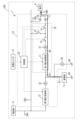
- FIG. 1 is a block diagram schematically illustrating a power supply system including a power supply control device according to a first embodiment.
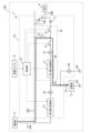
- FIG. 2 is an explanatory diagram conceptually showing the operation of the power supply system during discharging operation.
- FIG. 3 is an explanatory diagram conceptually showing the operation of the power supply system during regenerative operation.
- FIG. 4 is an explanatory diagram conceptually showing the operation of the power supply system during charging operation.
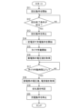
- FIG. 5 is a flowchart of processing performed by the power supply control device according to the first embodiment.
- FIG. 6 is an explanatory diagram conceptually showing the operation of the power supply system according to the second embodiment when the charging/discharging unit is caused to perform a discharging operation during at least a part of the period in which power is supplied from the power unit to the load. .
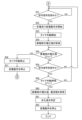
- FIG. 7 is a part of a flowchart of processing performed by the power supply control device according to the second embodiment.
- FIG. 8 is the remaining part of the flowchart of the process performed by the
- [1] Comprising a power supply unit, a power path that is a path for supplying power from the power supply unit to a load, and a power storage unit that functions as a backup power source at least when power supply from the power supply unit is interrupted.
- a power supply control device used in a power supply system and mounted on a vehicle, A discharging operation that supplies power to the load based on the power from the power storage unit, a regeneration operation that supplies power to the power supply unit based on the power from the power storage unit, and a regeneration operation that supplies power to the power supply unit based on the power from the power storage unit.
- a charging/discharging unit that performs a charging operation of supplying power to the power storage unit; a control unit that controls the charging and discharging unit; has The control unit determines the degree of deterioration of the power storage unit based on a voltage value of the power storage unit and a current value flowing through the power storage unit during at least one of the regeneration operation and the charging operation after the regeneration operation. Determine power control device.
- the power supply control device in [1] above performs a regenerative operation to supply power to the power supply unit based on the power from the power storage unit. Then, this power supply control device determines the degree of deterioration of the power storage unit based on the voltage value of the power storage unit and the current value flowing through the power storage unit during at least one of the regeneration operation and the charging operation after the regeneration operation. Therefore, this power supply control device can determine the degree of deterioration while suppressing wasteful power consumption of the power storage unit.
- the control unit causes the charging/discharging unit to perform the regenerative operation when a starting switch for starting the vehicle is switched to an OFF state, and controls the charging/discharging unit during the regenerative operation and during the charging operation after the regenerative operation.
- the power supply control device according to [1], wherein the degree of deterioration of the power storage unit is determined based on the voltage value of the power storage unit and the current value flowing through the power storage unit in at least one of the above.
- the power supply control device in [2] above determines the degree of deterioration by causing the charging/discharging unit to perform regenerative operation when the vehicle's starting switch is turned off. It is easy to avoid power shortages.
- the control unit causes the charging/discharging unit to perform the regeneration operation until a predetermined regeneration end condition is satisfied, and the control unit causes the charging and discharging unit to perform the regeneration operation until the regeneration end condition is satisfied.
- the charging/discharging unit is caused to perform the charging operation, and the voltage value of the power storage unit and the current value flowing through the power storage unit during at least one of the regeneration operation and the charging operation after the regeneration operation are adjusted.
- the power supply control device according to [2], wherein the degree of deterioration of the power storage unit is determined based on the power storage unit.
- the power supply control device in [3] above causes the charging/discharging section to perform a regenerative operation when the vehicle's starting switch is turned off, and causes the charging/discharging section to continue the charging operation after the regenerative operation is completed. . Therefore, this power supply control device easily puts the charging/discharging unit into a state where backup operation is possible at the time of starting the vehicle.
- the control unit causes the charging/discharging unit to perform the regenerative operation when a starting switch for starting the vehicle is in an on state, and performs at least one of the regenerative operation and the charging operation after the regenerative operation.
- the power supply control device according to [1], wherein the degree of deterioration of the power storage unit is determined based on the voltage value of the power storage unit and the current value flowing through the power storage unit in either one.
- the power supply control device in [4] above can determine the degree of deterioration while suppressing wasteful power consumption of the power storage unit while the vehicle is running.
- the control unit causes the regeneration operation to be performed so that the discharge current from the charging/discharging unit is constant, and the control unit performs the regeneration operation based on the voltage value of the power storage unit and the current value flowing through the power storage unit during the regeneration operation.
- the power supply control device according to any one of [1] to [4], wherein the degree of deterioration of the power storage unit is determined.
- the above power supply control device [5] can determine the degree of deterioration of the power storage unit while performing regenerative operation with a constant current.
- the control unit causes the charging operation to be performed so that the charging current from the charging/discharging unit is constant, and the control unit performs the charging operation based on the voltage value of the power storage unit and the current value flowing through the power storage unit during the charging operation.
- the power supply control device according to any one of [1] to [4], wherein the degree of deterioration of the power storage unit is determined.
- the above power supply control device [6] can determine the degree of deterioration of the power storage unit while performing a charging operation with a constant current.
- a power supply control device used in a power supply system and mounted on a vehicle, a charging/discharging unit that performs a discharging operation that supplies power to the load based on the power from the power storage unit, and a charging operation that supplies power to the power storage unit based on the power from the power supply unit; a control unit that controls the charging and discharging unit; has The control section causes the charging/discharging section to perform the discharging operation during at least a part of the period during which power is supplied from the power supply section to the load, and during the discharging operation and during the charging operation after the discharging operation.
- a power supply control device that determines the degree of deterioration of the power storage unit based on a voltage value of the power storage unit and a current value flowing through the
- the power supply control device in [7] above causes the charging/discharging unit to perform a discharging operation during at least a part of the period during which power is supplied from the power supply unit to the load. Therefore, the discharge current from the charging/discharging section is effectively used for the operation of the load.
- the power supply control device determines the degree of deterioration of the power storage unit based on the voltage value of the power storage unit and the current value flowing through the power storage unit during at least one of the discharging operation and the charging operation after the discharging operation. do. Therefore, this power supply control device can determine the degree of deterioration while suppressing wasteful power consumption of the power storage unit.
- the control unit causes the charging and discharging unit to perform the discharging operation so that the output voltage of the charging and discharging unit becomes higher than the output voltage of the power supply unit during at least a part of the period, and According to [7], the degree of deterioration of the power storage unit is determined based on the voltage value of the power storage unit and the current value flowing through the power storage unit during at least one of operation and the charging operation after the discharging operation. power control device.
- the above power supply control device [8] can more reliably supply power from the power storage unit to the load during the period in which power is supplied from the power supply unit to the load.
- the load outputs a permission signal that permits discharging from the power storage unit to the load
- the control unit causes the charging/discharging unit to perform the discharging operation when receiving the permission signal, and controls the power storage unit in at least one of the discharging operation and the charging operation after the discharging operation.
- the power supply control device according to [7] or [8], wherein the degree of deterioration of the power storage unit is determined based on a voltage value and a current value flowing through the power storage unit.
- the above power supply control device [9] starts the discharging operation upon receiving the permission signal from the load, so it is easy to perform the discharging operation at the timing when the load requires power supply.
- the control unit performs the discharging operation so that the discharge current from the charging/discharging unit is constant during at least a portion of the period, and controls the voltage value of the power storage unit and the power storage unit during the discharging operation.
- the power supply control device according to any one of [7] to [9], wherein the degree of deterioration of the power storage unit is determined based on a current value flowing through the power storage unit.
- the above power supply control device [10] can determine the degree of deterioration of the power storage unit while supplying a constant current to the load.
- the control unit causes the charging operation to be performed so that the charging current supplied to the power storage unit is constant, and adjusts the voltage value of the power storage unit and the current value flowing through the power storage unit at the time of the charging operation.
- the power supply control device according to any one of [7] to [9], wherein the degree of deterioration of the power storage unit is determined based on the power storage unit.
- the power supply control device of [11] above can determine the degree of deterioration of the power storage unit while performing a charging operation with a constant current.
- FIG. 1 shows a power supply system 1 including a power supply control device 10 according to a first embodiment.
- the power supply system 1 is a system mounted on the vehicle 100, and is a system that can supply power to various loads.
- the vehicle 100 on which the power supply system 1 is mounted is, for example, an electric vehicle, a plug-in hybrid vehicle, a hybrid vehicle, or the like, and may be another type of vehicle.
- the power supply system 1 is a system mounted on a vehicle 100.
- the area of the vehicle 100 is conceptually indicated by a dashed-dotted line frame.
- the power supply system 1 includes a power supply section 2 , a power storage section 3 , a load 4 , a power path 5 , a starting switch 9 , and a power supply control device 10 .
- the power supply unit 2 is an on-vehicle power supply that can supply power to the load 4.
- the power supply unit 2 is configured as, for example, a known vehicle battery such as a lead battery.
- the power supply section 2 may be constituted by a battery other than a lead battery, and may have a power source means other than the battery instead of or in addition to the battery.
- the positive electrode of the power supply section 2 is electrically connected to the power path 5 in a short-circuited configuration.
- the negative electrode of the power supply unit 2 is electrically connected to the ground 90 in a short-circuited configuration.
- the power supply unit 2 applies a predetermined DC voltage (for example, 12V) to the power path 5 when fully charged.
- the power supply unit 2 supplies power to a power path 5 and supplies power to the load 4 via the power path 5 .
- the power storage unit 3 functions as a backup power supply at least when power supply from the power supply unit 2 is interrupted.
- the power storage unit 3 may include a capacitor (for example, an electric double layer capacitor (EDLC) or a lithium ion capacitor (LiC)), a battery, or other power storage means.
- the configuration may include the following.
- the positive electrode of power storage unit 3 is electrically connected to first conductive path 81 in a short-circuited configuration.
- the negative electrode of power storage unit 3 is electrically connected to ground 90 in a short-circuited configuration.
- the voltage of power storage unit 3 may be higher or lower than the voltage of power supply unit 2.
- the voltage of power storage unit 3 is the voltage applied to first conductive path 81 by power storage unit 3 .
- the voltage of power storage unit 3 has the same meaning as the output voltage of power storage unit 3, and has the same meaning as the charging voltage of power storage unit 3.
- the voltage of the power supply section 2 is the voltage applied to the power path 5 by the power supply section 2.
- the voltage of the power supply section 2 has the same meaning as the output voltage of the power supply section 2, and has the same meaning as the charging voltage of the power supply section 2.
- Power storage unit 3 supplies power to load 4 via power path 5 at least when power supply from power supply unit 2 is interrupted.
- voltage is a voltage relative to a ground potential (for example, 0 V), and is a potential difference from the ground potential.
- the voltage applied to the power path 5 is the potential difference between the potential of the power path 5 and the ground potential.
- the load 4 is an electrical component mounted on the vehicle 100.
- the load 4 operates by receiving power supplied via the power path 5.
- the power path 5 is a path through which electric power based on the power source section 2 is transmitted, and is a path through which power based on the power source section 2 is supplied to the load 4.
- the power path 5 includes an input power path 5A and an output power path 5B arranged closer to the load 4 than the input power path 5A.
- the same or substantially the same voltage as the voltage of the power supply section 2 is applied to the power path 5 (more specifically, the input side power path 5A).
- One end of the power path 5 (more specifically, one end of the input power path 5A) is electrically connected to the positive electrode of the power supply unit 2 in a short-circuited configuration.
- the other end of the power path 5 (more specifically, the other end of the output side power path 5B) is electrically connected to one end of the load 4 in a short-circuited configuration.
- the power path 5 may be provided with a relay or a fuse.
- the starting switch 9 corresponds to an ignition switch that starts the engine. If the vehicle 100 is an electric vehicle, this corresponds to a power switch that starts the EV system.
- the power supply control device 10 is used in the power supply system 1. Power supply control device 10 is mounted on vehicle 100.
- the power supply control device 10 includes a first voltage converter 11, a second voltage converter 12, switches 13, 14, 15, diodes 16, 17, a voltage detector 20, a first current detector 21, It has a second current detection section 22, a control section 23, a first conductive path 81, and a second conductive path 82.
- the first voltage converter 11 is a device that performs voltage conversion between the first conductive path 81 and the second conductive path 82.
- the first voltage converter 11 is configured by a known voltage converter circuit such as a DC/DC converter.
- the first voltage conversion unit 11 can perform a first conversion operation of stepping down or stepping up the DC voltage applied to the first conductive path 81 and apply an output voltage to the second conductive path 82 .
- the first voltage conversion unit 11 can perform a second conversion operation of stepping down or stepping up the DC voltage applied to the second conductive path 82 and apply an output voltage to the first conductive path 81 .
- the operation of the first voltage conversion section 11 is controlled by the control section 23.
- the switches 13, 14, and 15 are composed of semiconductor switches such as FETs (Field Effect Transistors), mechanical relays, and the like.
- One end of the switch 13 is electrically connected to the second conductive path 82 .
- the other end of switch 13 is electrically connected to one end of switch 14 and one end of switch 15 .
- the other end of the switch 14 is electrically connected to the anode of a diode 17 and, via the diode 17, to the output power path 5B.
- the other end of the switch 15 is electrically connected to the input power path 5A.
- the operations of the switches 13, 14, and 15 are controlled by the control section 23.
- the anode of the diode 16 is electrically connected to the other end of the input power path 5A.
- a cathode of the diode 16 is electrically connected to one end of the output power path 5B.
- the anode of diode 17 is electrically connected to the other end of switch 14 .
- a cathode of the diode 17 is electrically connected to the output power path 5B.
- the first voltage conversion section 11 and the switches 13, 14, and 15 constitute a charging/discharging section 18.
- the charging/discharging unit 18 performs a discharging operation to supply power to the load 4 based on the power from the power storage unit 3 .
- the charging/discharging unit 18 performs the above-mentioned discharging operation by the first voltage conversion unit 11 performing the first conversion operation, the switches 13 and 14 being in the on state, and the switch 15 being in the off state. I do.
- the charge/discharge unit 18 performs a regenerative operation to supply power to the power supply unit 2 based on the power from the power storage unit 3 . As shown in FIG.
- the charging/discharging unit 18 performs the regeneration operation by the first voltage conversion unit 11 performing the first conversion operation, the switches 13 and 15 being in the on state, and the switch 14 being in the off state. I do.
- the charging/discharging unit 18 performs a charging operation to supply power to the power storage unit 3 based on the power from the power supply unit 2 .
- the charging/discharging unit 18 performs the above-mentioned charging operation by causing the first voltage converting unit 11 to perform the second conversion operation, the switches 13 and 15 to be in the on state, and the switch 14 to be in the off state. I do.
- the second voltage converter 12 is a device that performs voltage conversion between the first conductive path 81 and the power path 5 (more specifically, the input power path 5A).
- the second voltage conversion section 12 is configured by a known voltage conversion circuit such as a DC/DC converter.
- the second voltage conversion unit 12 performs a third conversion operation of stepping down or boosting the DC voltage applied to the first conductive path 81 and applying an output voltage to the power path 5 (more specifically, the input power path 5A). can be done.
- the second voltage converter 12 performs a fourth conversion operation of stepping down or boosting the DC voltage applied to the power path 5 (more specifically, the input power path 5A) and applying an output voltage to the first conductive path 81. can be done.
- the second voltage converter 12 is used for charging and discharging a smaller amount of power than the first voltage converter 11 .
- the operation of the second voltage conversion section 12 is controlled by the control section 23.
- the voltage detection unit 20 can detect the voltage of the power storage unit 3.
- the voltage detection section 20 is configured, for example, as a known voltage detection circuit.
- the voltage detection unit 20 may or may not divide the detected value.
- Voltage detection section 20 outputs a signal that can specify the voltage of power storage section 3 to control section 23 .
- the first current detection unit 21 can detect the current value flowing through the power storage unit 3 when the first voltage conversion unit 11 is performing the first conversion operation or the second conversion operation. That is, the first current detection section 21 can detect the value of the current flowing through the power storage section 3 during the discharging operation, the regeneration operation, and the charging operation.
- the first current detection section 21 is configured using, for example, a shunt resistor or a current transformer.
- the first current detection unit 21 outputs a signal that can specify the value of the current flowing through the power storage unit 3 to the control unit 23.
- the second current detection unit 22 can detect the current value flowing through the power storage unit 3 when the second voltage conversion unit 12 is performing the third conversion operation or the fourth conversion operation.
- the second current detection section 22 is configured using, for example, a shunt resistor or a current transformer.
- the second current detection unit 22 outputs a signal that can specify the value of the current flowing through the power storage unit 3 to the control unit 23.
- the control unit 23 includes a control device.
- This control device is an information processing device having arithmetic functions and information processing functions, and includes, for example, a CPU and a storage unit.
- Control unit 23 can acquire the voltage value of power storage unit 3 based on the signal from voltage detection unit 20 .
- Control unit 23 can acquire the value of the current flowing through power storage unit 3 based on the signal from first current detection unit 21 .
- Control unit 23 can acquire the value of the current flowing through power storage unit 3 based on the signal from second current detection unit 22 .
- the control section 23 can control the operations of the first voltage conversion section 11, the second voltage conversion section 12, and the switches 13, 14, and 15.
- the control section 23 can control the operation of the charging/discharging section 18.
- Control unit 23 determines the degree of deterioration of power storage unit 3 based on the voltage value of power storage unit 3 and the current value flowing through power storage unit 3 during the charging operation after the regeneration operation.
- the control unit 23 controls power storage based on the voltage value of the power storage unit 3 acquired based on the signal from the voltage detection unit 20 and the current value flowing through the power storage unit 3 acquired based on the signal from the first current detection unit 21.
- the degree of deterioration is SOH (State of Health), and more specifically, SOHR.
- SOHR is the rate of increase in internal resistance of power storage unit 3.
- SOHR is calculated by the following formula (1).
- SOHR R/R0...(1)
- R is the current internal resistance of power storage unit 3.
- R0 is the internal resistance of power storage unit 3 at the beginning of use or at an initial stage. R0 may be stored in advance in the control unit 23, or may be a value calculated at the beginning of use.
- R is calculated by the following formula (2).
- R (V2-V1)/(I2-I1)....(2)
- V1 is the voltage value of power storage unit 3 at the start of determination (in this embodiment, at the start of charging operation).
- V2 is the voltage value of the power storage unit 3 at the end of the determination (in this embodiment, at the end of the charging operation).
- I1 is a current value (0 A in this embodiment) flowing through power storage unit 3 at the start of determination (in this embodiment, at the start of charging operation).
- I2 is the current value flowing through the power storage unit 3 at the end of the determination (in this embodiment, at the end of the charging operation).
- the determination time Tc from the start of determination to the end of determination is set to the time required to determine the degree of deterioration.
- the control unit 23 causes the charging/discharging unit 18 to perform a regenerative operation when the starting switch 9 is switched from the on state to the off state, and the voltage value of the power storage unit 3 and the voltage flowing to the power storage unit 3 during the charging operation after the regenerative operation.
- the degree of deterioration of power storage unit 3 is determined based on the current value.
- the control unit 23 causes the charging/discharging unit 18 to perform the regeneration operation until a predetermined regeneration end condition is satisfied.
- the regeneration end condition is that the voltage value of power storage unit 3 becomes equal to or lower than a predetermined charging start voltage Vc.
- the charging start voltage Vc is set so that the time necessary for determining the degree of deterioration is ensured when the charging operation is performed until the voltage value of the power storage unit 3 reaches the charging target voltage.
- the control unit 23 causes the charge/discharge unit 18 to perform a charging operation, and controls the power storage unit 3 based on the voltage value of the power storage unit 3 and the current value flowing through the power storage unit 3 during the charging operation. Determine the degree of deterioration.
- the control unit 23 performs the charging operation so that the charging current from the charging/discharging unit 18 is constant, and adjusts the voltage of the power storage unit 3 based on the voltage value of the power storage unit 3 and the current value flowing through the power storage unit 3 during the charging operation. Determine the degree of deterioration.
- the control unit 23 performs the process of the flowchart shown in FIG. 5, for example, when the start switch 9 is switched from the on state to the off state.
- step S11 the control unit 23 causes the charging/discharging unit 18 to start a regeneration operation.
- step S12 the control unit 23 determines whether the regeneration end condition is satisfied. If the control unit 23 determines that the regeneration end condition is not satisfied (NO in step S12), the process returns to step S12. That is, the control unit 23 causes the charging/discharging unit 18 to continue performing the regenerative operation until the regeneration end condition is satisfied.
- control unit 23 determines that the regeneration end condition is satisfied (YES in step S12)
- the control unit 23 stops the regeneration operation of the charging/discharging unit 18 in step S13, and charges with a constant current in step S14.
- the control unit 23 starts the operation of a timer and starts measuring the elapsed time from the start of the charging operation (the elapsed time from the start of the determination).
- control unit 23 acquires the voltage value of power storage unit 3 at the start of determination (at the start of charging operation).
- step S17 the control unit 23 determines whether the operating time of the timer is equal to or longer than the determination time Tc.
- the control unit 23 determines that the operating time of the timer is not longer than the determination time Tc (NO in step S17)
- the process returns to step S17. That is, the control unit 23 causes the charging/discharging unit 18 to continue performing the charging operation until the timer operation time becomes equal to or longer than the determination time Tc.
- control unit 23 determines the voltage of the power storage unit 3 at the end of the determination (at the end of the charging operation) in step S18. The value and the current value flowing through the power storage unit 3 are acquired. Control unit 23 determines the degree of deterioration of power storage unit 3 in step S19. Control unit 23 determines the degree of deterioration based on the voltage value of power storage unit 3 acquired in step S16, and the voltage value of power storage unit 3 and the current value flowing through power storage unit 3 acquired in step S18. The control unit 23 stops the charging operation in step S20. After that, the control unit 23 ends the process shown in FIG. 5.
- the power supply control device 10 performs a regenerative operation to supply power to the power supply unit 2 based on the power from the power storage unit 3. Then, power supply control device 10 determines the degree of deterioration of power storage unit 3 based on the voltage value of power storage unit 3 and the current value flowing through power storage unit 3 during the charging operation after the regeneration operation. Therefore, power supply control device 10 can determine the degree of deterioration while suppressing wasteful power consumption of power storage unit 3.
- the power supply control device 10 causes the charging/discharging unit 18 to perform a regenerative operation to determine the degree of deterioration when the starting switch 9 of the vehicle 100 is switched to the OFF state. It is easy to avoid insufficient power supply.
- the power supply control device 10 causes the charging/discharging unit 18 to perform a regenerative operation when the starting switch 9 of the vehicle 100 is switched to the off state, and causes the charging/discharging unit 18 to continue to perform the charging operation after the regenerative operation is completed. let Therefore, the power supply control device 10 easily puts the charging/discharging section 18 into a state where the backup operation is possible at the time of starting the vehicle 100.
- the power supply control device 10 can determine the degree of deterioration of the power storage unit 3 while performing a charging operation with a constant current.
- the power supply control device of the second embodiment causes the charging/discharging unit to perform a discharging operation during at least a part of the period during which power is supplied from the power supply unit to the load, and changes the voltage value of the power storage unit during the discharging operation and the voltage value flowing to the power storage unit.
- the degree of deterioration of the power storage unit is determined based on the current value. Note that the power supply system of the second embodiment is the same as the power supply system shown in FIG. The second embodiment will be described below using FIG. 1.
- the control unit 23 causes the charging/discharging unit 18 to perform a discharging operation during at least a part of the period during which power is supplied from the power supply unit 2 to the load 4, and controls the voltage value of the power storage unit 3 and the voltage flowing to the power storage unit 3 during the discharging operation.
- the degree of deterioration of power storage unit 3 is determined based on the current value.
- the control unit 23 controls power storage based on the voltage value of the power storage unit 3 acquired based on the signal from the voltage detection unit 20 and the current value flowing through the power storage unit 3 acquired based on the signal from the first current detection unit 21. Determine the degree of deterioration of section 3.
- the control unit 23 causes the charging/discharging unit 18 to perform a discharging operation so that the output voltage of the charging/discharging unit 18 becomes higher than the output voltage of the power supply unit 2 during at least a part of the period. As a result, as shown in FIG. 6, power supply from the charge/discharge unit 18 is prioritized over power supply from the power supply unit 2. Control unit 23 determines the degree of deterioration of power storage unit 3 based on the voltage value of power storage unit 3 and the current value flowing through power storage unit 3 during this discharging operation.
- the load 4 has a control circuit and an output section that outputs a signal to the outside.
- the load 4 When the load 4 performs a predetermined operation, it outputs a permission signal that permits discharging from the power storage unit 3 to the load 4.
- the permission signal is input to the power supply control device 10.
- the control unit 23 When receiving the permission signal, the control unit 23 causes the charging/discharging unit 18 to perform a discharging operation, and determines the degree of deterioration of the power storage unit 3 based on the voltage value of the power storage unit 3 and the current value flowing through the power storage unit 3 during the discharging operation. Determine.
- the control unit 23 performs the discharging operation so that the discharge current from the charging/discharging unit 18 is constant during at least a part of the period, and adjusts the voltage value of the power storage unit 3 and the current value flowing through the power storage unit 3 during the discharging operation. Based on this, the degree of deterioration of power storage unit 3 is determined.
- the control unit 23 performs the processes shown in the flowcharts shown in FIGS. 7 and 8, for example, when the starting switch 9 is switched from an off state to an on state.
- Control unit 23 first determines in step S32 whether the voltage value of power storage unit 3 is equal to or lower than charging start voltage Vc. If the control unit 23 determines that the voltage value of the power storage unit 3 is equal to or lower than the charging start voltage Vc (YES in step S32), the control unit 23 causes the charging/discharging unit 18 to start the charging operation in step S34. At this time, the control unit 23 causes the charging operation to be performed so that the charging current from the charging/discharging unit 18 is constant.
- step S35 the control unit 23 starts the operation of a timer and starts measuring the elapsed time from the start of the charging operation (the elapsed time from the start of the determination).
- step S36 control unit 23 acquires the voltage value of power storage unit 3 at the start of determination (at the start of charging operation).
- step S37 the control unit 23 determines whether the operating time of the timer is equal to or longer than the determination time Tc.
- the process returns to step S37. That is, the control unit 23 causes the charging/discharging unit 18 to continue performing the charging operation until the timer operation time becomes equal to or longer than the determination time Tc.
- control unit 23 determines the voltage of the power storage unit 3 at the end of the determination (at the end of the charging operation) in step S38. The value and the current value flowing through the power storage unit 3 are acquired. Control unit 23 determines the degree of deterioration of power storage unit 3 in step S39. Control unit 23 determines the degree of deterioration based on the voltage value of power storage unit 3 acquired in step S36, and the voltage value of power storage unit 3 and the current value flowing through power storage unit 3 acquired in step S38. The control unit 23 stops the charging operation by the charging/discharging unit 18 in step S40. Thereafter, the control unit 23 ends the processing shown in FIGS. 7 and 8.
- step S32 determines in step S32 that the voltage value of the power storage unit 3 is not equal to or lower than the charging start voltage Vc
- the control unit 23 determines in step S51 of FIG. 8 whether a permission signal is being received. If the control unit 23 is not receiving the permission signal (NO in step S51), it enters a standby state until it receives the permission signal.
- control unit 23 determines that the permission signal has been received (YES in step S51)
- the control unit 23 causes the charging/discharging unit 18 to start the discharging operation in step S52.
- the control unit 23 causes the charging and discharging unit 18 to perform a discharging operation so that the discharge current from the charging and discharging unit 18 becomes constant.
- step S53 the control unit 23 starts the operation of a timer and measures the elapsed time from the start of the discharging operation (the elapsed time from the start of the determination).
- control unit 23 acquires the voltage value of power storage unit 3 at the start of determination (at the start of discharging operation).
- control unit 23 determines whether the voltage value of power storage unit 3 is equal to or lower than charging start voltage Vc.
- the control unit 23 determines that the voltage value of the power storage unit 3 is equal to or lower than the charging start voltage Vc (YES in step S55)
- the control unit 23 stops the operation of the timer (step S56), and stops the discharging operation. (Step S57)
- the process moves to step S34 in FIG. That is, control unit 23 causes charging/discharging unit 18 to start a charging operation, and determines the degree of deterioration of power storage unit 3 based on the voltage value of power storage unit 3 and the current value flowing through power storage unit 3 during the charging operation.
- control unit 23 determines whether or not a permission signal is being received in step S58. If the control unit 23 determines that the permission signal is not being received (NO in step S58), the process returns to step S51.
- step S58 determines whether the permission signal is being received (YES in step S58). That is, the control unit 23 determines whether the elapsed time since the start of the discharging operation (the elapsed time since the start of the determination) is equal to or longer than the determination time Tc. If the control unit 23 determines that the operating time of the timer is not longer than the determination time Tc (NO in step S59), the process returns to step S55.
- control unit 23 determines that the voltage value of the power storage unit 3 becomes equal to or lower than the charging start voltage Vc during the discharging operation, it switches to the charging operation, and changes the voltage value of the power storage unit 3 during the charging operation and the voltage value of the power storage unit 3 during the charging operation.
- the degree of deterioration of power storage unit 3 is determined based on the value of current flowing through.
- step S60 the voltage of the power storage unit 3 at the end of the determination (at the end of the discharging operation) is determined. The value and the current value flowing through the power storage unit 3 are acquired. Then, control unit 23 determines the degree of deterioration of power storage unit 3 in step S61. Control unit 23 determines the degree of deterioration based on the voltage value of power storage unit 3 acquired in step S54, and the voltage value of power storage unit 3 and the current value flowing through power storage unit 3 acquired in step S60. The control unit 23 stops the discharging operation by the charging/discharging unit 18 in step S62. Thereafter, the control unit 23 ends the processing shown in FIGS. 7 and 8.
- the power supply control device 10 of the second embodiment causes the charging/discharging unit 18 to perform a discharging operation during at least part of the period in which power is supplied from the power supply unit 2 to the load 4. Therefore, the discharge current from the charging/discharging section 18 is effectively used for the operation of the load 4. Then, power supply control device 10 determines the degree of deterioration of power storage unit 3 based on the voltage value of power storage unit 3 and the current value flowing through power storage unit 3 during this discharging operation. Therefore, power supply control device 10 can determine the degree of deterioration while suppressing wasteful power consumption of power storage unit 3.
- control section 23 causes the charging/discharging section 18 to perform a discharging operation so that the output voltage of the charging/discharging section 18 becomes higher than the output voltage of the power supply section 2 during at least a part of the period, and during this discharging operation.
- the degree of deterioration of power storage unit 3 is determined based on the voltage value of power storage unit 3 and the current value flowing through power storage unit 3 at . Therefore, power supply control device 10 can more reliably supply power from power storage unit 3 to load 4 during the period in which power is supplied from power supply unit 2 to load 4 .
- the power supply control device 10 starts the discharging operation upon receiving the permission signal from the load 4, it is easy to perform the discharging operation at the timing when the load 4 requires power supply.
- the degree of deterioration of the power storage unit 3 can be determined while supplying a constant current to the load 4.
- the degree of deterioration is determined during the charging operation after the regeneration operation, but the degree of deterioration may be determined during the regeneration operation. In this case, it is preferable to perform the regeneration operation so that the discharge current from the charging/discharging section is constant.
- the degree of deterioration is determined when the starting switch is in the off state, but the degree of deterioration may be determined when the starting switch is in the on state.
- the degree of deterioration is determined during the discharging operation to the load, but the degree of deterioration may be determined during the charging operation performed after the discharging operation. In this case, it is preferable to perform the charging operation so that the charging current supplied to the power storage unit is constant.
- Power supply system 2 Power supply unit 3: Power storage unit 4: Load 5: Power line 5A: Input side power line 5B: Output side power line 9: Start switch 10: Power supply control device 11: First voltage conversion unit 12: First 2 Voltage conversion section 13: Switch 14: Switch 15: Switch 16: Diode 17: Diode 18: Charging/discharging section 20: Voltage detection section 21: First current detection section 22: Second current detection section 23: Control section 81: First 1 conductive path 82 : 2nd conductive path 90 : Ground 100 : Vehicle Tc : Judgment time Vc : Charging start voltage
Landscapes
- Engineering & Computer Science (AREA)
- Life Sciences & Earth Sciences (AREA)
- Sustainable Development (AREA)
- Sustainable Energy (AREA)
- Power Engineering (AREA)
- Transportation (AREA)
- Mechanical Engineering (AREA)
- Charge And Discharge Circuits For Batteries Or The Like (AREA)
Abstract
Description
電源部と、前記電源部に基づく電力を負荷に供給する経路である電力路と、少なくとも前記電源部からの電力供給が途絶えた場合にバックアップ電源として機能する蓄電部と、を備えた電源システムに用いられ、車両に搭載される電源制御装置であって、
前記蓄電部からの電力に基づいて前記負荷に電力を供給する放電動作と、前記蓄電部からの電力に基づいて前記電源部に電力を供給する回生動作と、前記電源部からの電力に基づいて前記蓄電部に電力を供給する充電動作と、を行う充放電部と、
前記充放電部を制御する制御部と、
を有し、
前記制御部は、前記回生動作時と前記回生動作後の前記充電動作時との少なくともいずれか一方における前記蓄電部の電圧値及び前記蓄電部に流れる電流値に基づいて前記蓄電部の劣化度を判定する。
前記蓄電部からの電力に基づいて前記負荷に電力を供給する放電動作と、前記蓄電部からの電力に基づいて前記電源部に電力を供給する回生動作と、前記電源部からの電力に基づいて前記蓄電部に電力を供給する充電動作と、を行う充放電部と、
前記充放電部を制御する制御部と、
を有し、
前記制御部は、前記回生動作時と前記回生動作後の前記充電動作時との少なくともいずれか一方における前記蓄電部の電圧値及び前記蓄電部に流れる電流値に基づいて前記蓄電部の劣化度を判定する
電源制御装置。
〔1〕に記載の電源制御装置。
〔2〕に記載の電源制御装置。
〔1〕に記載の電源制御装置。
〔1〕から〔4〕のいずれか一つに記載の電源制御装置。
〔1〕から〔4〕のいずれか一つに記載の電源制御装置。
前記蓄電部からの電力に基づいて前記負荷に電力を供給する放電動作と、前記電源部からの電力に基づいて前記蓄電部に電力を供給する充電動作と、を行う充放電部と、
前記充放電部を制御する制御部と、
を有し、
前記制御部は、前記電源部から前記負荷に電力を供給する期間の少なくとも一部期間において前記充放電部に前記放電動作を行わせ、前記放電動作時と前記放電動作後の前記充電動作時との少なくともいずれか一方における前記蓄電部の電圧値及び前記蓄電部に流れる電流値に基づいて前記蓄電部の劣化度を判定する
電源制御装置。
〔7〕に記載の電源制御装置。
前記制御部は、前記許可信号を受信した場合に前記充放電部に前記放電動作を行わせ、前記放電動作時と前記放電動作後の前記充電動作時との少なくともいずれか一方における前記蓄電部の電圧値及び前記蓄電部に流れる電流値に基づいて前記蓄電部の劣化度を判定する
〔7〕又は〔8〕に記載の電源制御装置。
〔7〕から〔9〕のいずれか一つに記載の電源制御装置。
〔7〕から〔9〕のいずれか一つに記載の電源制御装置。
1.電源システム1の概要
図1には、第1実施形態の電源制御装置10を備えた電源システム1が示される。電源システム1は、車両100に搭載されるシステムであり、様々な負荷に電力を供給し得るシステムである。電源システム1が搭載される車両100は、例えば、電気自動車、ブラグインハイブリッド車、ハイブリッド車等の車両であり、その他の種類の車両であってもよい。
電源制御装置10は、電源システム1に用いられる。電源制御装置10は、車両100に搭載される。電源制御装置10は、第1電圧変換部11と、第2電圧変換部12と、スイッチ13,14,15と、ダイオード16,17と、電圧検出部20と、第1電流検出部21と、第2電流検出部22と、制御部23と、第1導電路81と、第2導電路82と、を有する。
SOHR=R/R0 ・・・(1)
Rは、現在の蓄電部3の内部抵抗である。R0は、使用開始時又は初期の蓄電部3の内部抵抗である。R0は、制御部23に予め記憶されていてもよいし、使用開始時に算出した値であってもよい。
R=(V2-V1)/(I2-I1) ・・・(2)
V1は、判定開始時(本実施形態では充電動作開始時)の蓄電部3の電圧値である。V2は、判定終了時(本実施形態では充電動作終了時)の蓄電部3の電圧値である。I1は、判定開始時(本実施形態では充電動作開始時)の蓄電部3に流れる電流値(本実施形態では0A)である。I2は、判定終了時(本実施形態では充電動作終了時)の蓄電部3に流れる電流値である。判定開始から判定終了までの判定時間Tcは、劣化度の判定に必要な時間が設定される。
制御部23は、例えば始動スイッチ9がオン状態からオフ状態に切り替わった場合に、図5に示されるフローチャートの処理を行う。制御部23は、まずステップS11にて、充放電部18に回生動作を開始させる。制御部23は、ステップS12にて、回生終了条件が成立したか否かを判定する。制御部23は、回生終了条件が成立していないと判定した場合(ステップS12にてNOの場合)、ステップS12の処理に戻る。つまり、制御部23は、回生終了条件が成立するまで、充放電部18に回生動作を継続して行わせる。
電源制御装置10は、蓄電部3からの電力に基づいて電源部2に電力を供給する回生動作を行う。そして、電源制御装置10は、回生動作後の充電動作時における蓄電部3の電圧値及び蓄電部3に流れる電流値に基づいて蓄電部3の劣化度を判定する。したがって、電源制御装置10は、蓄電部3の無駄な電力消費を抑えつつ、劣化度を判定することができる。
第2実施形態の電源制御装置は、電源部から負荷に電力を供給する期間の少なくとも一部期間において充放電部に放電動作を行わせ、放電動作時における蓄電部の電圧値及び蓄電部に流れる電流値に基づいて蓄電部の劣化度を判定する。なお、第2実施形態の電源システムは、図1に示される電源システムと同じである。以下では、図1を用いて、第2実施形態について説明する。
制御部23は、許可信号を受信した場合に充放電部18に放電動作を行わせ、放電動作時における蓄電部3の電圧値及び蓄電部3に流れる電流値に基づいて蓄電部3の劣化度を判定する。
本開示は、上記記述及び図面によって説明した実施形態に限定されるものではない。例えば、上述又は後述の実施形態の特徴は、矛盾しない範囲であらゆる組み合わせが可能である。また、上述又は後述の実施形態のいずれの特徴も、必須のものとして明示されていなければ省略することもできる。更に、上述した実施形態は、次のように変更されてもよい。
2 :電源部
3 :蓄電部
4 :負荷
5 :電力路
5A :入力側電力路
5B :出力側電力路
9 :始動スイッチ
10 :電源制御装置
11 :第1電圧変換部
12 :第2電圧変換部
13 :スイッチ
14 :スイッチ
15 :スイッチ
16 :ダイオード
17 :ダイオード
18 :充放電部
20 :電圧検出部
21 :第1電流検出部
22 :第2電流検出部
23 :制御部
81 :第1導電路
82 :第2導電路
90 :グラウンド
100 :車両
Tc :判定時間
Vc :充電開始電圧
Claims (11)
- 電源部と、前記電源部に基づく電力を負荷に供給する経路である電力路と、少なくとも前記電源部からの電力供給が途絶えた場合にバックアップ電源として機能する蓄電部と、を備えた電源システムに用いられ、車両に搭載される電源制御装置であって、
前記蓄電部からの電力に基づいて前記負荷に電力を供給する放電動作と、前記蓄電部からの電力に基づいて前記電源部に電力を供給する回生動作と、前記電源部からの電力に基づいて前記蓄電部に電力を供給する充電動作と、を行う充放電部と、
前記充放電部を制御する制御部と、
を有し、
前記制御部は、前記回生動作時と前記回生動作後の前記充電動作時との少なくともいずれか一方における前記蓄電部の電圧値及び前記蓄電部に流れる電流値に基づいて前記蓄電部の劣化度を判定する
電源制御装置。 - 前記制御部は、前記車両を始動させる始動スイッチがオフ状態に切り替わった場合に前記充放電部に前記回生動作を行わせ、前記回生動作時と前記回生動作後の前記充電動作時との少なくともいずれか一方における前記蓄電部の電圧値及び前記蓄電部に流れる電流値に基づいて前記蓄電部の劣化度を判定する
請求項1に記載の電源制御装置。 - 前記制御部は、前記始動スイッチがオフ状態に切り替わった場合に、予め定められた回生終了条件が成立するまで前記充放電部に前記回生動作を行わせ、前記回生終了条件が成立した場合に前記充放電部に前記充電動作を行わせ、前記回生動作時と前記回生動作後の前記充電動作時との少なくともいずれか一方における前記蓄電部の電圧値及び前記蓄電部に流れる電流値に基づいて前記蓄電部の劣化度を判定する
請求項2に記載の電源制御装置。 - 前記制御部は、前記車両を始動させる始動スイッチがオン状態のときに前記充放電部に前記回生動作を行わせ、前記回生動作時と前記回生動作後の前記充電動作時との少なくともいずれか一方における前記蓄電部の電圧値及び前記蓄電部に流れる電流値に基づいて前記蓄電部の劣化度を判定する
請求項1に記載の電源制御装置。 - 前記制御部は、前記充放電部からの放電電流が一定となるように前記回生動作を行わせ、前記回生動作時における前記蓄電部の電圧値及び前記蓄電部に流れる電流値に基づいて前記蓄電部の劣化度を判定する
請求項1から請求項4のいずれか一項に記載の電源制御装置。 - 前記制御部は、前記充放電部からの充電電流が一定となるように前記充電動作を行わせ、前記充電動作時における前記蓄電部の電圧値及び前記蓄電部に流れる電流値に基づいて前記蓄電部の劣化度を判定する
請求項1から請求項4のいずれか一項に記載の電源制御装置。 - 電源部と、前記電源部に基づく電力を負荷に供給する経路である電力路と、少なくとも前記電源部からの電力供給が途絶えた場合にバックアップ電源として機能する蓄電部と、を備えた電源システムに用いられ、車両に搭載される電源制御装置であって、
前記蓄電部からの電力に基づいて前記負荷に電力を供給する放電動作と、前記電源部からの電力に基づいて前記蓄電部に電力を供給する充電動作と、を行う充放電部と、
前記充放電部を制御する制御部と、
を有し、
前記制御部は、前記電源部から前記負荷に電力を供給する期間の少なくとも一部期間において前記充放電部に前記放電動作を行わせ、前記放電動作時と前記放電動作後の前記充電動作時との少なくともいずれか一方における前記蓄電部の電圧値及び前記蓄電部に流れる電流値に基づいて前記蓄電部の劣化度を判定する
電源制御装置。 - 前記制御部は、前記少なくとも一部期間において、前記充放電部の出力電圧が前記電源部の出力電圧よりも高くなるように、前記充放電部に前記放電動作を行わせ、前記放電動作時と前記放電動作後の前記充電動作時との少なくともいずれか一方における前記蓄電部の電圧値及び前記蓄電部に流れる電流値に基づいて前記蓄電部の劣化度を判定する
請求項7に記載の電源制御装置。 - 前記負荷は、前記蓄電部から前記負荷への放電を許可する許可信号を出力するものであり、
前記制御部は、前記許可信号を受信した場合に前記充放電部に前記放電動作を行わせ、前記放電動作時と前記放電動作後の前記充電動作時との少なくともいずれか一方における前記蓄電部の電圧値及び前記蓄電部に流れる電流値に基づいて前記蓄電部の劣化度を判定する
請求項7又は請求項8に記載の電源制御装置。 - 前記制御部は、前記少なくとも一部期間において前記充放電部からの放電電流が一定となるように前記放電動作を行わせ、前記放電動作時における前記蓄電部の電圧値及び前記蓄電部に流れる電流値に基づいて前記蓄電部の劣化度を判定する
請求項7から請求項9のいずれか一項に記載の電源制御装置。 - 前記制御部は、前記蓄電部に供給される充電電流が一定となるように前記充電動作を行わせ、前記充電動作時における前記蓄電部の電圧値及び前記蓄電部に流れる電流値に基づいて前記蓄電部の劣化度を判定する
請求項7から請求項9のいずれか一項に記載の電源制御装置。
Priority Applications (4)
| Application Number | Priority Date | Filing Date | Title |
|---|---|---|---|
| JP2024511109A JP7639988B2 (ja) | 2022-03-31 | 2022-03-31 | 電源制御装置 |
| US18/850,624 US20250214484A1 (en) | 2022-03-31 | 2022-03-31 | Power supply control device |
| PCT/JP2022/016802 WO2023188367A1 (ja) | 2022-03-31 | 2022-03-31 | 電源制御装置 |
| CN202280093549.2A CN118843560A (zh) | 2022-03-31 | 2022-03-31 | 电源控制装置 |
Applications Claiming Priority (1)
| Application Number | Priority Date | Filing Date | Title |
|---|---|---|---|
| PCT/JP2022/016802 WO2023188367A1 (ja) | 2022-03-31 | 2022-03-31 | 電源制御装置 |
Publications (1)
| Publication Number | Publication Date |
|---|---|
| WO2023188367A1 true WO2023188367A1 (ja) | 2023-10-05 |
Family
ID=88200461
Family Applications (1)
| Application Number | Title | Priority Date | Filing Date |
|---|---|---|---|
| PCT/JP2022/016802 Ceased WO2023188367A1 (ja) | 2022-03-31 | 2022-03-31 | 電源制御装置 |
Country Status (4)
| Country | Link |
|---|---|
| US (1) | US20250214484A1 (ja) |
| JP (1) | JP7639988B2 (ja) |
| CN (1) | CN118843560A (ja) |
| WO (1) | WO2023188367A1 (ja) |
Cited By (1)
| Publication number | Priority date | Publication date | Assignee | Title |
|---|---|---|---|---|
| WO2025158637A1 (ja) * | 2024-01-26 | 2025-07-31 | 株式会社オートネットワーク技術研究所 | 車載用制御装置 |
Citations (3)
| Publication number | Priority date | Publication date | Assignee | Title |
|---|---|---|---|---|
| JP2012147529A (ja) * | 2011-01-07 | 2012-08-02 | Takenaka Komuten Co Ltd | 作業所電力制御システム |
| JP2016116362A (ja) * | 2014-12-16 | 2016-06-23 | トヨタ自動車株式会社 | 電気自動車 |
| JP2018170821A (ja) * | 2017-03-29 | 2018-11-01 | 株式会社オートネットワーク技術研究所 | 車載用電源システムの制御装置及び車載用電源装置 |
Family Cites Families (2)
| Publication number | Priority date | Publication date | Assignee | Title |
|---|---|---|---|---|
| DE102018103754A1 (de) * | 2017-02-20 | 2018-08-23 | Toyota Jidosha Kabushiki Kaisha | Brennstoffzellensteuerungsvorrichtung, Steuerungsverfahren derselben und Brennstoffzellenfahrzeug |
| KR102751287B1 (ko) * | 2019-09-18 | 2025-01-09 | 현대자동차주식회사 | 차량용 솔라 충전 시스템 및 방법 |
-
2022
- 2022-03-31 JP JP2024511109A patent/JP7639988B2/ja active Active
- 2022-03-31 WO PCT/JP2022/016802 patent/WO2023188367A1/ja not_active Ceased
- 2022-03-31 CN CN202280093549.2A patent/CN118843560A/zh active Pending
- 2022-03-31 US US18/850,624 patent/US20250214484A1/en active Pending
Patent Citations (3)
| Publication number | Priority date | Publication date | Assignee | Title |
|---|---|---|---|---|
| JP2012147529A (ja) * | 2011-01-07 | 2012-08-02 | Takenaka Komuten Co Ltd | 作業所電力制御システム |
| JP2016116362A (ja) * | 2014-12-16 | 2016-06-23 | トヨタ自動車株式会社 | 電気自動車 |
| JP2018170821A (ja) * | 2017-03-29 | 2018-11-01 | 株式会社オートネットワーク技術研究所 | 車載用電源システムの制御装置及び車載用電源装置 |
Cited By (1)
| Publication number | Priority date | Publication date | Assignee | Title |
|---|---|---|---|---|
| WO2025158637A1 (ja) * | 2024-01-26 | 2025-07-31 | 株式会社オートネットワーク技術研究所 | 車載用制御装置 |
Also Published As
| Publication number | Publication date |
|---|---|
| US20250214484A1 (en) | 2025-07-03 |
| JP7639988B2 (ja) | 2025-03-05 |
| JPWO2023188367A1 (ja) | 2023-10-05 |
| CN118843560A (zh) | 2024-10-25 |
Similar Documents
| Publication | Publication Date | Title |
|---|---|---|
| US20140132063A1 (en) | Vehicle power unit | |
| US11855475B2 (en) | Charge/discharge control apparatus | |
| CN112041200B (zh) | 车载用的备用电路及车载用的备用装置 | |
| WO2012008124A1 (ja) | 車両用電源装置 | |
| JP6969505B2 (ja) | 車載用の電源制御装置および車載用電源システム | |
| JP6732831B2 (ja) | 電源供給装置 | |
| JPH0461580B2 (ja) | ||
| JP5304279B2 (ja) | 蓄電装置 | |
| US11418050B2 (en) | Method for controlling discharge of power storage device | |
| WO2023188367A1 (ja) | 電源制御装置 | |
| JP7565001B2 (ja) | 車載用制御装置 | |
| JP5381360B2 (ja) | 電源装置 | |
| JP2022011203A (ja) | バックアップ電源装置及びバックアップ電源装置の制御方法 | |
| JP2017163713A (ja) | 充放電装置及び電源装置 | |
| JP2012244826A (ja) | 蓄電装置 | |
| JP6665719B2 (ja) | 電源制御装置、及び電源システム | |
| JPH09233727A (ja) | バッテリー充電装置 | |
| JP7234907B2 (ja) | 車載用電源制御装置、及び車載用電源装置 | |
| JP2019068662A (ja) | 電源供給システム | |
| JP7788079B2 (ja) | 車載用のバックアップ制御装置 | |
| US20250219401A1 (en) | Vehicle backup apparatus | |
| JP2022160011A (ja) | 放電制御装置、放電制御方法 | |
| WO2024004145A1 (ja) | 車載用のバックアップ制御装置 | |
| WO2024236727A1 (ja) | 車載用制御装置 | |
| JP2026019613A (ja) | 蓄電監視システム |
Legal Events
| Date | Code | Title | Description |
|---|---|---|---|
| 121 | Ep: the epo has been informed by wipo that ep was designated in this application |
Ref document number: 22933874 Country of ref document: EP Kind code of ref document: A1 |
|
| ENP | Entry into the national phase |
Ref document number: 2024511109 Country of ref document: JP Kind code of ref document: A |
|
| WWE | Wipo information: entry into national phase |
Ref document number: 202280093549.2 Country of ref document: CN |
|
| WWE | Wipo information: entry into national phase |
Ref document number: 18850624 Country of ref document: US |
|
| NENP | Non-entry into the national phase |
Ref country code: DE |
|
| 122 | Ep: pct application non-entry in european phase |
Ref document number: 22933874 Country of ref document: EP Kind code of ref document: A1 |
|
| WWP | Wipo information: published in national office |
Ref document number: 18850624 Country of ref document: US |