WO2023188305A1 - 情報処理装置、情報処理方法、及び、記録媒体 - Google Patents
情報処理装置、情報処理方法、及び、記録媒体 Download PDFInfo
- Publication number
- WO2023188305A1 WO2023188305A1 PCT/JP2022/016639 JP2022016639W WO2023188305A1 WO 2023188305 A1 WO2023188305 A1 WO 2023188305A1 JP 2022016639 W JP2022016639 W JP 2022016639W WO 2023188305 A1 WO2023188305 A1 WO 2023188305A1
- Authority
- WO
- WIPO (PCT)
- Prior art keywords
- information processing
- light
- imaging target
- information
- processing device
- Prior art date
- Legal status (The legal status is an assumption and is not a legal conclusion. Google has not performed a legal analysis and makes no representation as to the accuracy of the status listed.)
- Ceased
Links
Images




Classifications
-
- G—PHYSICS
- G06—COMPUTING OR CALCULATING; COUNTING
- G06V—IMAGE OR VIDEO RECOGNITION OR UNDERSTANDING
- G06V40/00—Recognition of biometric, human-related or animal-related patterns in image or video data
- G06V40/60—Static or dynamic means for assisting the user to position a body part for biometric acquisition
-
- A—HUMAN NECESSITIES
- A61—MEDICAL OR VETERINARY SCIENCE; HYGIENE
- A61B—DIAGNOSIS; SURGERY; IDENTIFICATION
- A61B3/00—Apparatus for testing the eyes; Instruments for examining the eyes
- A61B3/10—Objective types, i.e. instruments for examining the eyes independent of the patients' perceptions or reactions
- A61B3/13—Ophthalmic microscopes
-
- A—HUMAN NECESSITIES
- A61—MEDICAL OR VETERINARY SCIENCE; HYGIENE
- A61B—DIAGNOSIS; SURGERY; IDENTIFICATION
- A61B5/00—Measuring for diagnostic purposes; Identification of persons
- A61B5/117—Identification of persons
- A61B5/1171—Identification of persons based on the shapes or appearances of their bodies or parts thereof
-
- A—HUMAN NECESSITIES
- A61—MEDICAL OR VETERINARY SCIENCE; HYGIENE
- A61B—DIAGNOSIS; SURGERY; IDENTIFICATION
- A61B5/00—Measuring for diagnostic purposes; Identification of persons
- A61B5/117—Identification of persons
- A61B5/1171—Identification of persons based on the shapes or appearances of their bodies or parts thereof
- A61B5/1172—Identification of persons based on the shapes or appearances of their bodies or parts thereof using fingerprinting
-
- G—PHYSICS
- G01—MEASURING; TESTING
- G01N—INVESTIGATING OR ANALYSING MATERIALS BY DETERMINING THEIR CHEMICAL OR PHYSICAL PROPERTIES
- G01N21/00—Investigating or analysing materials by the use of optical means, i.e. using sub-millimetre waves, infrared, visible or ultraviolet light
- G01N21/17—Systems in which incident light is modified in accordance with the properties of the material investigated
-
- G—PHYSICS
- G01—MEASURING; TESTING
- G01S—RADIO DIRECTION-FINDING; RADIO NAVIGATION; DETERMINING DISTANCE OR VELOCITY BY USE OF RADIO WAVES; LOCATING OR PRESENCE-DETECTING BY USE OF THE REFLECTION OR RERADIATION OF RADIO WAVES; ANALOGOUS ARRANGEMENTS USING OTHER WAVES
- G01S17/00—Systems using the reflection or reradiation of electromagnetic waves other than radio waves, e.g. lidar systems
- G01S17/02—Systems using the reflection of electromagnetic waves other than radio waves
- G01S17/06—Systems determining position data of a target
- G01S17/08—Systems determining position data of a target for measuring distance only
-
- G—PHYSICS
- G06—COMPUTING OR CALCULATING; COUNTING
- G06T—IMAGE DATA PROCESSING OR GENERATION, IN GENERAL
- G06T1/00—General purpose image data processing
-
- G—PHYSICS
- G06—COMPUTING OR CALCULATING; COUNTING
- G06T—IMAGE DATA PROCESSING OR GENERATION, IN GENERAL
- G06T7/00—Image analysis
-
- G—PHYSICS
- G06—COMPUTING OR CALCULATING; COUNTING
- G06V—IMAGE OR VIDEO RECOGNITION OR UNDERSTANDING
- G06V40/00—Recognition of biometric, human-related or animal-related patterns in image or video data
- G06V40/10—Human or animal bodies, e.g. vehicle occupants or pedestrians; Body parts, e.g. hands
- G06V40/12—Fingerprints or palmprints
- G06V40/13—Sensors therefor
- G06V40/1318—Sensors therefor using electro-optical elements or layers, e.g. electroluminescent sensing
Definitions
- This disclosure relates to the technical field of information processing devices, information processing methods, and recording media.
- Patent Document 1 describes a non-contact type guide that stops the body in a certain position.
- the light emitted from the light source is divided into at least one and the other, one of the divided lights is irradiated from the light input/output section toward the measurement object, and the optical coherence tomography head converts the reflected light from the measurement object into the optical input/output section.
- Patent Document 2 describes a technique for acquiring an accurate tomographic image by taking in measurement light from an optical coherence tomography head as measurement light and supporting the light input/output part of an optical coherence tomography head so as to be rotatable around the measurement target.
- the distance between the imaging unit and the laser beam irradiation unit is adjusted each time to follow the change in the inner diameter of the tubular body, and the annular laser beam is reliably emitted.
- a technology for imaging is described in Patent Document 3.
- Patent Document 4 describes a technique of calculating image quality parameters of a tomographic image and displaying the calculated image quality parameters of a tomographic image on a display.
- the light emitted from the wavelength-swept laser light source is transmitted through a splitting/merging device that splits the light into an object beam and a reference beam, and a transparent substrate on which a structure with varying thickness is formed, and is irradiated onto the measurement target.
- a balanced photodetector that generates information about the change in the intensity ratio of the interference light between the object light and the reference light scattered from the object, and a balance type receiver that generates information about the change in the intensity ratio of the interference light between the object light and the reference light scattered from the object, and detects the depth direction of the measurement target based on the information about the change in the intensity ratio of the interference light.
- a control unit that acquires structural data; the control unit performs information processing that connects a plurality of pieces of structural data in the depth direction acquired while moving the irradiation position of the object light with reference to the position of the structure of the transparent substrate;
- An object of this disclosure is to provide an information processing device, an information processing method, and a recording medium that aim to improve the techniques described in prior art documents.
- One aspect of the information processing device includes a detection means for detecting an inter-object distance between an imaging object and a light irradiation unit that irradiates light that scans the imaging object, and when the inter-object distance is a desired distance. , and scan control means for starting irradiation of the light by the light irradiation section.
- One aspect of the information processing method is to detect an inter-object distance between an imaging object and a light irradiation unit that irradiates light that scans the imaging object, and when the inter-object distance is a desired distance, the light The irradiation unit starts irradiating the light.
- One aspect of the recording medium is to have a computer detect an inter-object distance between an imaging object and a light irradiation unit that irradiates light that scans the imaging object, and when the inter-object distance is a desired distance, A computer program for executing an information processing method for starting irradiation of the light by the light irradiation unit is recorded.
- FIG. 1 is a block diagram showing the configuration of an information processing apparatus in the first embodiment.
- FIG. 2 is a block diagram showing the configuration of an information processing device in the second embodiment.
- FIG. 3 is a diagram showing the configuration of an optical coherence tomography apparatus according to the second embodiment.
- FIG. 4 is a flowchart showing the flow of information processing operations performed by the information processing apparatus in the second embodiment.
- FIG. 5 is a block diagram showing the configuration of an information processing device in the third embodiment.
- FIG. 6 is a flowchart showing the flow of information processing operations performed by the information processing apparatus in the third embodiment.
- FIG. 7 is a conceptual diagram of information processing operations performed by the information processing apparatus in the third embodiment.
- FIG. 8 is a conceptual diagram of information processing operations performed by the information processing apparatus in the fourth embodiment.
- FIG. 1 is a block diagram showing the configuration of an information processing apparatus in the first embodiment.
- FIG. 2 is a block diagram showing the configuration of an information processing device in the second embodiment.
- FIG. 3
- FIG. 9 is a conceptual diagram of information processing operations performed by the information processing apparatus in the fourth embodiment.
- FIG. 10 is a block diagram showing the configuration of an information processing device in the fifth embodiment.
- FIG. 11 is a flowchart showing the flow of information processing operations performed by the information processing apparatus in the fifth embodiment.
- FIG. 12 is a conceptual diagram of information processing operations performed by the information processing apparatus in the fifth embodiment.
- a first embodiment of an information processing device, an information processing method, and a recording medium will be described. Below, a first embodiment of an information processing device, an information processing method, and a recording medium will be described using an information processing device 1 to which the first embodiment of the information processing device, information processing method, and recording medium is applied. . [1-1: Configuration of information processing device 1]
- FIG. 1 is a block diagram showing the configuration of an information processing device 1 in the first embodiment.
- the information processing device 1 includes a detection section 11 and a control section 12.
- the detection unit 11 detects an inter-object distance between an imaging target and a light irradiation unit that irradiates light that scans the imaging target.
- the control unit 12 starts irradiation of light by the light irradiation unit.
- the light irradiation unit starts emitting light when the distance between objects is a desired distance, that is, when the imaging target and the light irradiation unit are in an appropriate positional relationship. , it is possible to perform highly accurate optical coherence tomography imaging.
- a second embodiment of an information processing device, an information processing method, and a recording medium will be described.
- a second embodiment of the information processing apparatus, the information processing method, and the recording medium will be described using an information processing apparatus 2 to which the second embodiment of the information processing apparatus, the information processing method, and the recording medium is applied.
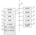
- FIG. 2 is a block diagram showing the configuration of the information processing device 2 in the second embodiment.
- the information processing device 2 includes a calculation device 21 and a storage device 22. Further, the information processing device 2 may include an optical coherence tomography device 100, a communication device 23, an input device 24, and an output device 25. However, the information processing device 2 does not need to include at least one of the optical coherence tomography device 100, the communication device 23, the input device 24, and the output device 25. If the information processing device 2 does not include the optical coherence tomography device 100, the information processing device 2 may transmit and receive information to and from the optical coherence tomography device 100 via the communication device 23.
- the arithmetic device 21, the storage device 22, the optical coherence tomography device 100, the communication device 23, the input device 24, and the output device 25 may be connected via a data bus 26.
- the arithmetic unit 21 is, for example, one of a CPU (Central Processing Unit), a GPU (Graphics Processing Unit), and an FPGA (Field Programmable Gate Array). Contains at least one.
- Arithmetic device 21 reads a computer program.
- the arithmetic device 21 may read a computer program stored in the storage device 22.
- the arithmetic device 21 reads a computer program stored in a computer-readable and non-temporary recording medium using a recording medium reading device (not shown) provided in the information processing device 2 (for example, an input device 24 described later). You can also read it using .
- the arithmetic device 21 may acquire a computer program from a device (not shown) located outside the information processing device 2 via the communication device 23 (or other communication device) (that is, it may not be downloaded). (or may be loaded). The arithmetic device 21 executes the loaded computer program. As a result, within the arithmetic device 21, a logical functional block for executing the operations that the information processing device 2 should perform is realized. That is, the arithmetic device 21 can function as a controller for realizing a logical functional block for executing operations (in other words, processing) that the information processing device 2 should perform.
- FIG. 2 shows an example of logical functional blocks implemented within the arithmetic unit 21 to execute information processing operations.
- the computing device 21 includes a detection unit 211 which is a specific example of a “detection unit”, a detection unit 211 which is a specific example of a “control unit”, and a detection unit 211 which is a specific example of a “transfer unit”.
- a moving unit 213, which is a specific example, is realized.
- the computing device 21 does not need to include the moving unit 213.
- the respective operations of the detection section 211, the control section 212, and the movement section 213 will be described later with reference to FIG. 4.
- the storage device 22 can store desired data.
- the storage device 22 may temporarily store a computer program executed by the arithmetic device 21.
- the storage device 22 may temporarily store data that is temporarily used by the arithmetic device 21 when the arithmetic device 21 is executing a computer program.
- the storage device 22 may store data that the information processing device 2 stores for a long period of time.
- the storage device 22 may include at least one of a RAM (Random Access Memory), a ROM (Read Only Memory), a hard disk device, a magneto-optical disk device, an SSD (Solid State Drive), and a disk array device. good. That is, the storage device 22 may include a non-temporary recording medium.
- the communication device 23 is capable of communicating with devices external to the information processing device 2 via a communication network (not shown).
- the communication device 23 may be a communication interface based on a standard such as Ethernet (registered trademark), Wi-Fi (registered trademark), Bluetooth (registered trademark), or the like.
- the input device 24 is a device that accepts information input to the information processing device 2 from outside the information processing device 2.
- the input device 24 includes an operating device (for example, at least one of a keyboard, a mouse trackball, a touch panel, a pointing device such as a pen tablet, a button, etc.) that can be operated by the operator of the information processing device 2.
- the input device 24 may include a reading device capable of reading information recorded as data on a recording medium that can be externally attached to the information processing device 2.
- the output device 25 is a device that outputs information to the outside of the information processing device 2.
- the output device 25 may output the information as an image.
- the output device 25 may include a display device (so-called display) capable of displaying an image indicating information desired to be output. Examples of display devices include liquid crystal displays, OLED (Organic Light Emitting Diode) displays, and the like.
- the output device 25 may output the information as audio. That is, the output device 25 may include an audio device (so-called speaker) that can output audio.
- the output device 25 may output information on paper. That is, the output device 25 may include a printing device (so-called printer) that can print desired information on paper.
- the input device 24 and the output device 25 may be integrally formed as a touch panel.
- FIG. 2 is an example, and devices other than those shown in FIG. 2 may be added, or some devices may not be provided. Further, some of the devices may be replaced with other devices having similar functions. Furthermore, some of the functions of the second embodiment may be provided by another device via a network. The functions of the second embodiment may be realized by being distributed among a plurality of devices. In this way, the hardware configuration shown in FIG. 2 can be changed as appropriate.
- the optical coherence tomography imaging apparatus 100 irradiates an object with a light beam while scanning in two dimensions, performs optical coherence tomography imaging, and generates three-dimensional brightness data of the object.
- Optical coherence tomography uses interference between object light and reference light to identify the position of the light scattering point in the target where the object light is scattered in the optical axis direction, that is, in the depth direction of the target, and This is a technology that obtains structural data that is spatially resolved in the direction of internal depth.
- Optical coherence tomography technology includes the Time Domain (TD-OCT) method and the Fourier Domain (FD-OCT) method, and the second embodiment employs the FD-OCT method.
- TD-OCT Time Domain
- FD-OCT Fourier Domain
- the second embodiment employs the FD-OCT method.
- the FD-OCT method when an object beam and a reference beam are caused to interfere with each other, an interference light spectrum in a wide wavelength band is measured, and this is Fourier transformed to obtain structural data in the depth direction.
- the coherence tomography apparatus 100 performs optical coherence tomography using the SS-OCT method.
- the optical coherence tomography imaging apparatus 100 performs spatial resolution in the in-plane direction by scanning the irradiation position of the object light in the in-plane direction perpendicular to the depth direction (also referred to as the "Z direction") of the imaging target O. , and it is possible to obtain tomographic structure data spatially resolved in the depth direction, that is, three-dimensional tomographic structure data of the imaging object O.
- FIG. 3 is a diagram showing a schematic configuration of an optical coherence tomography apparatus 100 employed in the second embodiment.
- the optical coherence tomography imaging apparatus 100 may image an imaging target O such as a finger of a measurement subject based on a three-dimensional measurement technique of optical coherence tomography and generate three-dimensional brightness data including the inside of the skin.
- the configuration diagram shown in FIG. 3 merely shows an example of an apparatus using optical coherence tomography technology, and an apparatus having a configuration other than that shown in FIG. 3 may be used.
- the optical coherence tomography imaging apparatus 100 may include a light source section 110, a branching/merging section 120, a light irradiation section 130, a mirror section 140, a light receiving section 150, and a signal processing section 160.
- the light irradiation unit 130 may include a scanning mirror and a lens.
- the optical coherence tomography imaging operation of the optical coherence tomography apparatus 100 may be controlled by the arithmetic device 21.
- the light source section 110 may be a laser that emits light while sweeping the wavelength.
- the light source unit 110 may generate and output wavelength-swept optical pulses.
- the light source unit 110 may generate a light pulse by sweeping the wavelength from 1250 nm to 1350 nm for a duration of 5 ⁇ s, for example.
- the branching/merging section 120 may branch the light emitted from the light source section 110 into object light and reference light.
- the object light may be irradiated onto the imaging target O through the light irradiation unit 130.
- the object light scattered in the imaging target O may return to the branching/merging section 120.
- the reference light may be irradiated onto the mirror unit 140 and reflected.
- the reference light reflected by the mirror section 140 may return to the branching/merging section 120.
- the object light scattered by the imaging target O and the reference light reflected by the mirror section 140 may interfere at the branching/merging section 120, and two interference lights may be generated. That is, the intensity ratio of the two interference lights may be determined by the phase difference between the object light and the reference light.
- the light receiving unit 150 may receive two interference lights and output a voltage according to the difference in intensity between the two interference lights.
- the voltage output by the light receiving section 150 may be input to the signal processing section 160.
- the signal processing unit 160 may generate interference light spectrum data based on information regarding a change in the wavelength of the light emitted by the light source unit 110 and information regarding a change in the intensity ratio of two interference lights.
- the signal processing unit 160 may perform Fourier transform on the generated interference light spectrum data to obtain data indicating the intensity of backscattered light (object light) at different depth positions in the depth direction (Z direction).
- the signal processing unit 160 may be supplied with an A-scan trigger signal from the light source unit 110 and may generate an A-scan waveform at predetermined intervals.
- the signal processing unit 160 may generate a waveform indicating the object light backscatter intensity at Nz locations as the A-scan waveform.
- the signal processing unit 160 may control the light irradiation unit 130 according to the A-scan trigger signal supplied from the light source unit 110.
- the light irradiation unit 130 may scan the irradiation position of the object light on the imaging target O.
- the light irradiation unit 130 may move the irradiation position of the object light in the scanning line direction (also referred to as "scanning fast axis direction” and "X direction").
- the signal processing unit 160 may repeatedly perform the A-scan operation for each irradiation position of the object light, and connect the A-scan waveforms for each irradiation position of the object light. Thereby, the signal processing unit 160 can obtain a two-dimensional intensity map of backscattered light (object light) in the scanning line direction (X direction) and depth direction (Z direction) as a tomographic image. .
- the operation of repeatedly performing the A-scan operation while moving in the scanning line direction (scanning fast axis direction, X direction) and connecting the measurement results will be referred to as "B-scan".
- the tomographic image obtained by the B-scan is two-dimensional brightness data that indicates the object light backscatter intensity at Nz ⁇ Nx points.
- the light irradiation unit 130 moves the irradiation position of the object light not only in the scanning line direction (X direction) but also in a direction perpendicular to the scanning line (also referred to as "scan slow axis direction” or "Y direction”). It's okay.
- the signal processing unit 160 may repeatedly perform the B-scan operation and connect the B-scan measurement results. Thereby, the signal processing unit 160 can acquire three-dimensional tomographic structure data.
- C scan the operation of repeatedly performing the B scan operation while moving in the direction perpendicular to the scanning line (Y direction) and connecting the measurement results.
- the tomographic structure data obtained by the C scan is three-dimensional brightness data indicating the object light backscatter intensity at the Nz ⁇ Nx ⁇ Ny point.
- the signal processing unit 160 sends the data after data conversion processing to the arithmetic unit 21 . Note that the operation by the signal processing section 160 may be performed by the arithmetic device 21. [Effects of optical coherence tomography imaging]
- a fingerprint image of the epidermis can be acquired without contact. This prevents the fingertips from coming into contact with a glass plate or the like, which is sanitary. Furthermore, unlike epidermal fingerprint imaging in which a fingerprint image is captured by bringing the fingertip into contact with a glass plate or the like, this method is not affected by deformation during contact. Moreover, a fingerprint image of the dermis can be obtained by optical coherence tomography. That is, since a fingerprint image can be obtained without being affected by the condition of the epidermis, a fingerprint image can be obtained even when it is difficult to read a fingerprint on the epidermis. Furthermore, when the epidermal fingerprint has been altered, it is suitable for detecting the alteration. [2-3: Information processing operation performed by information processing device 2]
- FIG. 4 is a flowchart showing the flow of information processing operations performed by the information processing device 2 in the second embodiment.
- the detection unit 211 detects the inter-object distance between the imaging target O and the light irradiation unit 130 that irradiates light that scans the imaging target O (step S20).
- the detection unit 211 may detect the distance d between the imaging target O and the light irradiation unit 130, as illustrated in FIG.
- the detection unit 211 may detect the distance between objects based on the B-scan results obtained by the optical coherence tomography apparatus 100.
- the inter-object distance may be a distance in the Z direction.
- the detection unit 211 may perform a B-scan of the imaging object O existing at a desired position on the XY plane, and detect the distance between the objects by using analysis of a two-dimensional cross-sectional image obtained by the B-scan.
- the detection unit 211 can detect the distance between the objects without adding a new device to the information processing device 2. . Further, the detection unit 211 can detect the distance between objects while continuing to monitor the imaging object O.
- the moving unit 213 moves the light irradiation unit 130 to a position suitable for scanning the imaging target O based on the distance between the objects (step S21).
- the light irradiation unit 130 may be placed on a vertically movable stage, for example, and configured to be vertically movable.
- the up-down direction may be the above-mentioned Z direction.
- the moving unit 213 may move the light irradiation unit 130 up and down so that the distance between the imaging target O and the light irradiation unit 130 becomes the optimum distance.
- the control unit 212 causes the light irradiation unit 130 to start irradiation of light (step S22).
- the light irradiation unit 130 may irradiate a light beam in the Z direction.
- the light irradiation unit 130 can start irradiation of light in a state where O and the light irradiation unit 130 are in an appropriate positional relationship, and highly accurate optical coherence tomography imaging can be performed.
- a third embodiment of an information processing device, an information processing method, and a recording medium will be described.
- a third embodiment of the information processing apparatus, the information processing method, and the recording medium will be described using an information processing apparatus 3 to which the third embodiment of the information processing apparatus, the information processing method, and the recording medium is applied.
- FIG. 5 is a block diagram showing the configuration of the information processing device 3 in the third embodiment.
- the information processing device 3 in the third embodiment includes an arithmetic device 21 and a storage device 22, similar to the information processing device 2 in the second embodiment. Furthermore, the information processing device 3 may include an optical coherence tomography device 100, a communication device 23, an input device 24, and an output device 25, similar to the information processing device 2 in the second embodiment. However, the information processing device 3 does not need to include the optical coherence tomography device 100 and at least one of the communication device 23, the input device 24, and the output device 25.
- the information processing device 3 in the third embodiment differs from the information processing device 2 in the second embodiment in that the arithmetic device 21 includes an output control unit 314. Other features of the information processing device 3 may be the same as other features of the information processing device 2 in the second embodiment. [3-2: Information processing operation performed by information processing device 3]
- FIG. 6 is a flowchart showing the flow of information processing operations performed by the information processing device 3 in the third embodiment.
- the output control unit 314 outputs guide information that guides the imaging target O to a desired position (step S30).
- the guide information may include at least one of visual information, auditory information, and tactile information.
- the output control unit 314 may control the output device 25 to output the guide information.
- the guide information includes at least visual information, and the visual information may be an image visibly displayed at a desired position.
- the output control unit 314 may display an aerial button B as guide information to lead to a desired position. [3-3: Air button B]
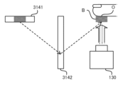
- FIG. 7 is a conceptual diagram of the air button B.
- the information processing device 3 in the third embodiment is provided with an air button display display 3141 and a retroreflector 3142 near the information processing device 3 in order to realize the air button B. You can leave it there.
- the aerial button display 3141 may be a liquid crystal display, an OLED (Organic Light Emitting Diode) display, or the like.
- the retroreflector 3142 may be a member capable of retroreflection.
- the aerial button B may be an image formed in the air by retroreflecting the image displayed by the aerial button display 3141 on the retroreflector 3142.
- the information processing device 3 can form an image in the air by employing the aerial button display 3141 and the retroreflector 3142.
- the aerial button display 3141 and the retroreflector 3142 may be provided depending on the positional relationship with the light irradiation unit 130. By appropriately providing the aerial button display 3141 and the retroreflector 3142, an image can be formed at a desired position.
- the output control unit 314 may display the aerial button B in the air at the optimal position for imaging the imaging target O.
- the output control unit 314 may form an aerial button B above the light irradiation unit 130.
- the aerial button B can be used to follow the finger and guide the finger to a desired position.
- the output control unit 314 may form a button-shaped image as the aerial button B.
- the detection unit 211 detects the distance between the imaging target O and the light irradiation unit 130.
- the output control unit 314 may change at least one of the color and shape of the aerial button B according to the detection result by the detection unit 211. At this time, the color may change as the target position approaches. For example, the output control unit 314 colors the aerial button B blue when the imaging target O does not exist, and colors the aerial button B red and blue when the imaging target O is not in a position suitable for imaging. If it is in a position suitable for imaging, the aerial button B may be colored green. Furthermore, instead of changing the color of the aerial button B in stages, the output control unit 314 may change the color of the aerial button B in a gradation according to the distance between objects.
- the aerial button B may be a three-dimensional image.
- the output control unit 314 may deform the aerial button B according to the detection result, that is, the position of the imaging target O.
- the output control unit 314 may change the shape of the aerial button B so that the button is pressed and becomes concave in accordance with the vertical movement of the imaging target O detected by the detection unit 211.
- the output control unit 314 may deform the aerial button B so that the area where the imaging target O is held up is concave.
- the output control unit 314 may deform the aerial button B to guide the imaging target O to a more appropriate position when the positions in the in-plane directions (XY directions) match.
- the output control unit 314 may guide the imaging target O to an accurate position by having the person to be measured push a button. Further, the output control unit 314 may change the shape of the aerial button B discontinuously or continuously.
- the output control unit 314 may further output at least one of auditory information and tactile information as guide information that leads to a desired position.
- the output control unit 314 may output, as auditory information, for example, a sound whose pitch changes depending on the distance between objects, a sound whose volume changes depending on the distance between objects, or the like. Further, the output control unit 314 may output a predetermined sound effect when the correct position is reached.
- the output control unit 314 may output, as the auditory information, a sound specifically instructing left, right, up, down, etc., for example.
- the output control unit 314 may output, as the tactile information, for example, wind whose direction changes depending on the distance between objects, wind whose strength changes depending on the distance between objects, or the like.
- the output control unit 314 may output, for example, ultrasonic waves whose wavelength changes depending on the distance between objects, as the tactile information.
- the detection unit 211 determines whether the imaging target O exists within a desired position range (step S31). If the imaging target O does not exist within the desired position range (step S31: No), the process moves to step S31.
- the detection unit 211 detects an object between the imaging target O and the light irradiation unit 130 that irradiates light to scan the imaging target O. The distance between them is detected (step S20).
- the moving unit 213 moves the light irradiation unit 130 to a position suitable for scanning the imaging target based on the distance between the objects (step S21).
- the control unit 212 causes the light irradiation unit 130 to start irradiation of light (step S22).
- the positional relationship between the imaging target O and the light irradiation unit 130 is appropriate. That is, in optical coherence tomography, it is preferable that the imaging target O and the light irradiation unit 130 can appropriately move relative to each other.
- the information processing device 3 may move the imaging object O guided by the guide information, or may move the light irradiation unit 130 based on the distance between objects.
- the information processing device 3 adjusts the positional relationship between the imaging target O and the light irradiation unit 130 to be appropriate by performing at least one of the output operation of the output control unit 314 and the movement operation of the movement unit 213. Good too.
- optical coherence tomography can be performed with high precision. That is, it is preferable that the imaging object O and the light irradiation section 130 are located at the same position in a plane in a direction perpendicular to the direction in which the light irradiation section 130 irradiates light.
- the output operation of the output control unit 314 can lead to a positional relationship in which light is irradiated perpendicularly to the imaging target O.
- the information processing device 3 may move the imaging target O guided by the guide information, particularly regarding movement in the XY directions. Moreover, the information processing device 3 may move the light irradiation unit 130 based on the distance between objects, especially regarding movement in the Z direction. [3-4: Technical effects of information processing device 3]
- the information processing device 3 in the third embodiment displays an image that is visibly displayed in a space where no substance exists, so it is possible to guide the imaging target to a desired position in a completely non-contact state. I can do it. Moreover, since the information processing device 3 changes at least one of the color and shape of the image according to the distance between the objects, it can assist in making it easier for the imaging object O to move to an appropriate position.
- the information processing device 3 in the third embodiment guides the imaging target O in the in-plane direction and the distance direction, and further adjusts the distance direction mechanically, so that an appropriate positional relationship can be obtained with high accuracy.
- a fourth embodiment of an information processing device, an information processing method, and a recording medium will be described. Below, a fourth embodiment of the information processing apparatus, the information processing method, and the recording medium will be described using an information processing apparatus 4 to which the fourth embodiment of the information processing apparatus, the information processing method, and the recording medium is applied. .
- the information processing device 4 in the fourth embodiment differs from the information processing device 3 in the third embodiment in the output operation by the output control unit 314. Other features of the information processing device 4 may be the same as other features of the information processing device 3. [4-1: When performing optical coherence tomography imaging of the imaging target O from above]
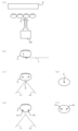
- FIG. 8 is a conceptual diagram when the light irradiation unit 130 performs optical coherence tomography imaging of the imaging target O from above.
- the light irradiation unit 130 may be configured to irradiate light from above onto the imaging target O that exists below the light irradiation unit 130.
- the output control unit 314 may output one guide light beam from the side to the desired position P as guide information for guiding to the desired position.
- the person to be measured may move his or her finger so that the guide light hits the center of the finger pad.
- the output control unit 314 may output two guide light beams to a desired position P as guide information for guiding to a desired position.
- the output control unit 314 may specify one desired position P using two guide light beams.
- FIGS. 8(d) and (f) illustrate how the imaging target O looks when observed from above. As illustrated in FIGS. 8(c) and 8(d), when the imaging target O is located at a desired height, a single point designated by the symbol P is formed by the light beam. On the other hand, as illustrated in FIGS. 8(c) and 8(d), when the imaging target O is located vertically shifted from the desired height, the points formed by the light beam are marked P1 and P2. There will be two with .
- FIG. 9 is a conceptual diagram when the light irradiation unit 130 performs optical coherence tomography imaging of the imaging target O from below. As illustrated in FIG. 9A, the light irradiation unit 130 may be configured to irradiate the imaging target O located above the light irradiation unit 130 with a light beam from below.
- the output control unit 314 may output one guide light beam from the side to the desired position P as guide information for guiding to the desired position.
- the person to be measured may move his or her finger so that the guide light hits the center of the finger pad.
- the output control unit 314 may output two guide light beams to the desired position P as guide information for guiding to the desired position.
- the output control unit 314 may specify one desired position P using two guide light beams.
- FIGS. 9(d) and (f) illustrate how the imaging target O looks when observed from below. As illustrated in FIGS. 9(c) and 9(d), when the imaging target O is located at a desired height, a single point designated by the symbol P is formed by the light beam. On the other hand, as illustrated in FIGS. 9(c) and 9(d), when the imaging target O is located vertically shifted from the desired height, the points formed by the light beam are marked P1 and P2. There will be two with . The person to be measured may move his or her finger so that one point of guide light hits the center of the finger pad. The output control unit 314 may guide the point to a position where exactly one point is formed.
- the information processing device 4 uses a camera (not shown) to image the imaging target O from below, and displays the image on the display D installed with the display surface facing upward. You may display the results.
- the imaging result may be an optical coherence tomographic image.
- Display D may display a finger pad and a beam pointing downward.
- the display D may display the distance between the imaging target O and the light irradiation unit 130.
- the camera may be a stereo camera, and the image displayed on the display D may be a stereo image.
- the output control unit 314 may further output at least one of auditory information and tactile information as guide information that leads to a desired position.
- the output control unit 314 may output, as auditory information, for example, a sound whose pitch changes depending on the distance between objects, a sound whose volume changes depending on the distance between objects, or the like.
- the output control unit 314 may output, as the auditory information, a sound specifically instructing left, right, up, down, etc., for example. Further, the output control unit 314 may output a predetermined sound effect when the correct position is reached.
- the output control unit 314 may output, as the tactile information, for example, wind whose direction changes depending on the distance between objects, wind whose strength changes depending on the distance between objects, or the like.
- the output control unit 314 may output, for example, ultrasonic waves whose wavelength changes depending on the distance between objects, as the tactile information.
- the information processing device 4 in the fourth embodiment guides the imaging target to a desired position using at least one of visual information, auditory information, and tactile information, so that the imaging target O and the light irradiation unit 130 are arranged in an appropriate positional relationship. It is possible to perform coherence tomography imaging in this state.
- a fifth embodiment of an information processing device, an information processing method, and a recording medium will be described.
- a fifth embodiment of the information processing apparatus, the information processing method, and the recording medium will be described using an information processing apparatus 5 to which the fifth embodiment of the information processing apparatus, the information processing method, and the recording medium is applied.
- FIG. 10 is a block diagram showing the configuration of the information processing device 5 in the fifth embodiment.
- the information processing device 5 in the fifth embodiment includes an arithmetic device 21 and a storage device 22, similar to the information processing device 3 in the third embodiment and the information processing device 4 in the fourth embodiment. It is equipped with Furthermore, the information processing device 5 includes an optical coherence tomography device 100, a communication device 23, an input device 24, similar to the information processing device 3 in the third embodiment and the information processing device 4 in the fourth embodiment. It may also include an output device 25. However, the information processing device 5 does not need to include the optical coherence tomography device 100 and at least one of the communication device 23, the input device 24, and the output device 25.
- the output control unit 314 included in the arithmetic device 21 performs the first output control.
- the difference is that it includes a section 5141 and a second output control section 5142.
- Other features of the information processing device 5 may be the same as other features of at least one of the information processing device 3 in the third embodiment and the information processing device 4 in the fourth embodiment.
- FIG. 11 is a flowchart showing the flow of information processing operations performed by the information processing device 5 in the fifth embodiment.
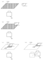
- FIG. 12 is a conceptual diagram showing the flow of information processing operations performed by the information processing device 5 in the fifth embodiment.
- the first output control unit 5141 outputs first guide information that guides the imaging target O to a desired position range (step S50). As illustrated in FIG. 12A, the first output control unit 5141 generates a first guide image as first guide information that directs the measurement subject's attention to move the imaging subject O to a desired location. 5141I may be output.
- the first guide information may be information indicating a range that can be photographed by the light irradiation unit 130.
- the first guide information may be information indicating a movable range of the light irradiation unit 130 in the XY plane.
- the detection unit 211 determines whether the imaging target O exists within a desired position range (step S51). If the imaging target O does not exist within the desired position range (step S51: No), the process moves to step S51.
- the second output control unit 5142 controls the second output control unit 5142 to guide the imaging target O to the desired position.
- Guide information is output (step S52).
- the second output control unit 5142 may output a second guide image 5142I as second guide information that allows the imaging target O to be precisely aligned to a desired position.
- the second guide information may have a U-shape (or U-shape, concave-shape) or the like so as to guide not only the position of the finger but also the direction of the finger.
- the output control unit 314 operates the first output control unit 5141 at the start of operation, and when the imaging target enters a desired position range, the output control unit 314 controls the operation of the first output control unit 5141 to a second output control. The operation may be switched to the operation of the section 5142.
- the detection unit 211 detects the inter-object distance between the imaging target and the light irradiation unit 130 that irradiates light that scans the imaging target (step S20).
- the moving unit 213 moves the light irradiation unit 130 to a position suitable for scanning the imaging target based on the distance between the objects (step S21).
- the control unit 212 causes the light irradiation unit 130 to start irradiation of light (step S22).
- the second output control unit 5142 controls the position of the imaging target O in step S52.
- the moving unit 213 may output the second guide information to a position corresponding to the position of the imaging target O, and move the light irradiation unit 130 to a position corresponding to the position of the imaging target O. That is, the second guide information may be information indicating the range in which the light irradiation unit 130 can photograph after moving in the XY directions.
- the information processing device 5 in the fifth embodiment can make the person to be measured perform rough movements and fine movements by outputting guide information divided into stages. [6: Sixth embodiment]
- a sixth embodiment of an information processing device, an information processing method, and a recording medium will be described. Below, a sixth embodiment of the information processing device, the information processing method, and the recording medium will be described using an information processing device 6 to which the sixth embodiment of the information processing device, the information processing method, and the recording medium is applied. .
- the information processing device 6 in the sixth embodiment differs from the information processing device 2 in the second embodiment to the information processing device 5 in the fifth embodiment in the initial position of the light irradiation unit 130.
- Other features of the information processing device 6 may be the same as at least one other feature of the information processing devices 2 to 5.
- the initial position of the light irradiation unit 130 is determined based on statistical information of the position where the imaging target O was present when the detection unit 211 started operating in the past. For example, the location where the imaging target O is likely to be located may be biased depending on the posture that the person being measured is likely to take.
- the moving unit 213 stores in the storage device 22 the positions where the plurality of measurement subjects first put their fingers over the light irradiation unit 130 and the position of the light irradiation unit 130 when the light irradiation unit 130 starts irradiating light. You may let them.
- the moving unit 213 may move the light irradiating unit 130 in advance to a position that is statistically likely to be held over first before starting the information processing operation.
- the moving unit 213 may determine the initial position of the light irradiation unit 130 based on history information of the position where the person to be measured first placed his or her finger over the light irradiation unit 130 .
- the moving unit 213 may associate the initial position of the light irradiation unit 130 with a time zone or a day of the week.
- the moving unit 213 may determine the initial position according to the day of the week, time of day, or the like. Depending on the day of the week and the time of day, locations where the imaging target is likely to exist are often biased. That is, the method for setting the initial position may be arbitrarily changed depending on the environment in which it is used.
- the information processing device 6 in the sixth embodiment determines the amount of movement of the light irradiation unit 130 by determining the initial position of the light irradiation unit 130 based on the statistical information of the position where the imaging target O existed at the start of the past detection operation. It is possible to reduce the operating load and suppress the operating load. [7: Additional notes]
- Detection means for detecting an inter-object distance between an imaging target and a light irradiation unit that irradiates light that scans the imaging target; and scanning control means for starting the light irradiation by the light irradiation unit when the distance between the objects is a desired distance.
- the information processing device according to supplementary note 1, further comprising a moving unit that moves the light irradiation unit to a position suitable for scanning the imaging target based on the distance between the objects.
- [Additional note 3] further comprising output means for outputting guide information that guides the imaging target to a desired position
- the information processing device according to Supplementary note 1 or 2 wherein the guide information includes at least one of visual information, auditory information, and tactile information.
- the visual information is an image visibly displayed at the desired position.
- the output means changes at least one of the color and shape of the image depending on the distance between objects.
- the output means is first output means for outputting first guide information that guides the imaging target to a desired position range; a second output means for outputting second guide information that guides the imaging target to the desired position;
- the first output means operates,
- the information processing device according to any one of Supplementary Notes 3 to 5, wherein when the imaging target enters the desired position range, the operation of the first output means is switched to the operation of the second output means.
- the information processing device according to any one of Supplementary Notes 1 to 6, wherein the initial position of the light irradiation unit is determined based on statistical information of the position where the imaging target was present when the detection unit started operating in the past.
Landscapes
- Engineering & Computer Science (AREA)
- Physics & Mathematics (AREA)
- Health & Medical Sciences (AREA)
- Life Sciences & Earth Sciences (AREA)
- General Physics & Mathematics (AREA)
- Theoretical Computer Science (AREA)
- Human Computer Interaction (AREA)
- Multimedia (AREA)
- Electromagnetism (AREA)
- General Health & Medical Sciences (AREA)
- Animal Behavior & Ethology (AREA)
- Biomedical Technology (AREA)
- Public Health (AREA)
- Surgery (AREA)
- Molecular Biology (AREA)
- Medical Informatics (AREA)
- Veterinary Medicine (AREA)
- Heart & Thoracic Surgery (AREA)
- Pathology (AREA)
- Biophysics (AREA)
- Computer Networks & Wireless Communication (AREA)
- Remote Sensing (AREA)
- Radar, Positioning & Navigation (AREA)
- Immunology (AREA)
- Biochemistry (AREA)
- Analytical Chemistry (AREA)
- Chemical & Material Sciences (AREA)
- Computer Vision & Pattern Recognition (AREA)
- Ophthalmology & Optometry (AREA)
- Investigating Or Analysing Materials By Optical Means (AREA)
Priority Applications (3)
| Application Number | Priority Date | Filing Date | Title |
|---|---|---|---|
| PCT/JP2022/016639 WO2023188305A1 (ja) | 2022-03-31 | 2022-03-31 | 情報処理装置、情報処理方法、及び、記録媒体 |
| JP2024511057A JP7736170B2 (ja) | 2022-03-31 | 2022-03-31 | 情報処理装置、情報処理方法、及び、記録媒体 |
| US18/712,289 US20250014392A1 (en) | 2022-03-31 | 2022-03-31 | Information processing apparatus, information processing method, and non-transitory recording medium |
Applications Claiming Priority (1)
| Application Number | Priority Date | Filing Date | Title |
|---|---|---|---|
| PCT/JP2022/016639 WO2023188305A1 (ja) | 2022-03-31 | 2022-03-31 | 情報処理装置、情報処理方法、及び、記録媒体 |
Publications (1)
| Publication Number | Publication Date |
|---|---|
| WO2023188305A1 true WO2023188305A1 (ja) | 2023-10-05 |
Family
ID=88199905
Family Applications (1)
| Application Number | Title | Priority Date | Filing Date |
|---|---|---|---|
| PCT/JP2022/016639 Ceased WO2023188305A1 (ja) | 2022-03-31 | 2022-03-31 | 情報処理装置、情報処理方法、及び、記録媒体 |
Country Status (3)
| Country | Link |
|---|---|
| US (1) | US20250014392A1 (https=) |
| JP (1) | JP7736170B2 (https=) |
| WO (1) | WO2023188305A1 (https=) |
Citations (4)
| Publication number | Priority date | Publication date | Assignee | Title |
|---|---|---|---|---|
| US20040002387A1 (en) * | 2002-06-26 | 2004-01-01 | Grady Daniel Patrick | Card reader and scanner device and methods of using same |
| JP2007101268A (ja) * | 2005-09-30 | 2007-04-19 | Fujifilm Corp | 光断層画像化装置 |
| JP2014188275A (ja) * | 2013-03-28 | 2014-10-06 | Nidek Co Ltd | 光断層像撮影装置 |
| JP2022033748A (ja) * | 2017-06-16 | 2022-03-02 | エス. ベルリン、マイケル | Octガイド緑内障手術のための方法およびシステム |
Family Cites Families (1)
| Publication number | Priority date | Publication date | Assignee | Title |
|---|---|---|---|---|
| JP7397196B2 (ja) * | 2020-06-25 | 2023-12-12 | 富士フイルム株式会社 | 情報処理装置、その作動方法及び作動プログラム |
-
2022
- 2022-03-31 JP JP2024511057A patent/JP7736170B2/ja active Active
- 2022-03-31 WO PCT/JP2022/016639 patent/WO2023188305A1/ja not_active Ceased
- 2022-03-31 US US18/712,289 patent/US20250014392A1/en active Pending
Patent Citations (4)
| Publication number | Priority date | Publication date | Assignee | Title |
|---|---|---|---|---|
| US20040002387A1 (en) * | 2002-06-26 | 2004-01-01 | Grady Daniel Patrick | Card reader and scanner device and methods of using same |
| JP2007101268A (ja) * | 2005-09-30 | 2007-04-19 | Fujifilm Corp | 光断層画像化装置 |
| JP2014188275A (ja) * | 2013-03-28 | 2014-10-06 | Nidek Co Ltd | 光断層像撮影装置 |
| JP2022033748A (ja) * | 2017-06-16 | 2022-03-02 | エス. ベルリン、マイケル | Octガイド緑内障手術のための方法およびシステム |
Also Published As
| Publication number | Publication date |
|---|---|
| JPWO2023188305A1 (https=) | 2023-10-05 |
| US20250014392A1 (en) | 2025-01-09 |
| JP7736170B2 (ja) | 2025-09-09 |
Similar Documents
| Publication | Publication Date | Title |
|---|---|---|
| US10007989B2 (en) | OCT data processing method, storage medium storing program for executing the OCT data processing method, and processing device | |
| CN101288102A (zh) | 用于分析从样本所获得的三维数据集的方法、系统和计算机程序产品 | |
| JP6226523B2 (ja) | 被検体情報取得装置、表示方法、およびデータ処理装置 | |
| US20200214602A1 (en) | Measurement apparatus | |
| KR102049242B1 (ko) | 화상처리장치, 화상처리방법 및 광간섭 단층촬영 장치 | |
| US10779721B2 (en) | Optical coherence tomography cross view imaging | |
| CN103284684B (zh) | 光学装置及其运作方法 | |
| US20200085345A1 (en) | Object information acquisition apparatus and method of controlling the same | |
| US10130250B2 (en) | OCT data processing apparatus and OCT data processing program | |
| US20220065615A1 (en) | Optical coherence tomography device | |
| WO2023188305A1 (ja) | 情報処理装置、情報処理方法、及び、記録媒体 | |
| US12178605B2 (en) | Device, method, and program for visualizing network of blood vessels of skin | |
| US11238584B2 (en) | Device, method, and program for visualizing network of blood vessels of skin | |
| US20250131764A1 (en) | Image processing apparatus, image processing method, and non-transitory recording medium | |
| US20220214156A1 (en) | Optical coherence tomography apparatus, imaging method, and non-transitory computer readable medium storing imaging program | |
| JP6490171B2 (ja) | データ処理装置およびデータ処理方法 | |
| JP7750305B2 (ja) | 光干渉断層撮像解析装置、光干渉断層撮像解析方法、及び記録媒体 | |
| US20250218022A1 (en) | Information processing apparatus, information processing method, and non-transitory recording medium | |
| JP2019215333A (ja) | 光音響装置および制御方法 | |
| KR102550386B1 (ko) | 피부의 혈관망을 가시화하는 장치, 방법 및 프로그램 | |
| JPWO2018079765A1 (ja) | 画像処理装置、眼底撮像システム、画像処理方法、およびプログラム | |
| JP2019209055A (ja) | 光音響装置および制御方法 |
Legal Events
| Date | Code | Title | Description |
|---|---|---|---|
| 121 | Ep: the epo has been informed by wipo that ep was designated in this application |
Ref document number: 22935447 Country of ref document: EP Kind code of ref document: A1 |
|
| WWE | Wipo information: entry into national phase |
Ref document number: 18712289 Country of ref document: US |
|
| ENP | Entry into the national phase |
Ref document number: 2024511057 Country of ref document: JP Kind code of ref document: A |
|
| NENP | Non-entry into the national phase |
Ref country code: DE |
|
| 122 | Ep: pct application non-entry in european phase |
Ref document number: 22935447 Country of ref document: EP Kind code of ref document: A1 |