WO2023188305A1 - Information processing device, information processing method, and recording medium - Google Patents
Information processing device, information processing method, and recording medium Download PDFInfo
- Publication number
- WO2023188305A1 WO2023188305A1 PCT/JP2022/016639 JP2022016639W WO2023188305A1 WO 2023188305 A1 WO2023188305 A1 WO 2023188305A1 JP 2022016639 W JP2022016639 W JP 2022016639W WO 2023188305 A1 WO2023188305 A1 WO 2023188305A1
- Authority
- WO
- WIPO (PCT)
- Prior art keywords
- information processing
- light
- imaging target
- information
- processing device
- Prior art date
Links
- 230000010365 information processing Effects 0.000 title claims abstract description 193
- 238000003672 processing method Methods 0.000 title claims description 29
- 238000001514 detection method Methods 0.000 claims abstract description 31
- 238000003384 imaging method Methods 0.000 claims description 136
- 238000004590 computer program Methods 0.000 claims description 10
- 230000000007 visual effect Effects 0.000 claims description 10
- 230000001678 irradiating effect Effects 0.000 claims description 6
- 238000012014 optical coherence tomography Methods 0.000 description 48
- 238000012545 processing Methods 0.000 description 21
- 238000010586 diagram Methods 0.000 description 19
- 238000000034 method Methods 0.000 description 15
- 238000004891 communication Methods 0.000 description 14
- 238000005259 measurement Methods 0.000 description 13
- 230000008859 change Effects 0.000 description 12
- 230000000694 effects Effects 0.000 description 8
- 238000005516 engineering process Methods 0.000 description 4
- 230000006870 function Effects 0.000 description 4
- 230000003287 optical effect Effects 0.000 description 4
- 238000001228 spectrum Methods 0.000 description 4
- 238000000547 structure data Methods 0.000 description 4
- 239000000470 constituent Substances 0.000 description 3
- 210000002615 epidermis Anatomy 0.000 description 3
- 239000003086 colorant Substances 0.000 description 2
- 239000011521 glass Substances 0.000 description 2
- 239000004973 liquid crystal related substance Substances 0.000 description 2
- 230000008569 process Effects 0.000 description 2
- 239000000758 substrate Substances 0.000 description 2
- 238000010408 sweeping Methods 0.000 description 2
- 238000003325 tomography Methods 0.000 description 2
- 230000004075 alteration Effects 0.000 description 1
- 238000004458 analytical method Methods 0.000 description 1
- 238000013459 approach Methods 0.000 description 1
- 238000000149 argon plasma sintering Methods 0.000 description 1
- 238000004364 calculation method Methods 0.000 description 1
- 238000006243 chemical reaction Methods 0.000 description 1
- 210000004207 dermis Anatomy 0.000 description 1
- 238000000691 measurement method Methods 0.000 description 1
- 238000007639 printing Methods 0.000 description 1
- 230000009467 reduction Effects 0.000 description 1
- 230000001953 sensory effect Effects 0.000 description 1
- 210000003491 skin Anatomy 0.000 description 1
- 239000007787 solid Substances 0.000 description 1
- 230000003595 spectral effect Effects 0.000 description 1
- 239000000126 substance Substances 0.000 description 1
- 238000012546 transfer Methods 0.000 description 1
Images


Classifications
-
- A—HUMAN NECESSITIES
- A61—MEDICAL OR VETERINARY SCIENCE; HYGIENE
- A61B—DIAGNOSIS; SURGERY; IDENTIFICATION
- A61B3/00—Apparatus for testing the eyes; Instruments for examining the eyes
- A61B3/10—Objective types, i.e. instruments for examining the eyes independent of the patients' perceptions or reactions
- A61B3/13—Ophthalmic microscopes
-
- A—HUMAN NECESSITIES
- A61—MEDICAL OR VETERINARY SCIENCE; HYGIENE
- A61B—DIAGNOSIS; SURGERY; IDENTIFICATION
- A61B5/00—Measuring for diagnostic purposes; Identification of persons
- A61B5/117—Identification of persons
- A61B5/1171—Identification of persons based on the shapes or appearances of their bodies or parts thereof
- A61B5/1172—Identification of persons based on the shapes or appearances of their bodies or parts thereof using fingerprinting
-
- G—PHYSICS
- G01—MEASURING; TESTING
- G01N—INVESTIGATING OR ANALYSING MATERIALS BY DETERMINING THEIR CHEMICAL OR PHYSICAL PROPERTIES
- G01N21/00—Investigating or analysing materials by the use of optical means, i.e. using sub-millimetre waves, infrared, visible or ultraviolet light
- G01N21/17—Systems in which incident light is modified in accordance with the properties of the material investigated
-
- G—PHYSICS
- G06—COMPUTING; CALCULATING OR COUNTING
- G06T—IMAGE DATA PROCESSING OR GENERATION, IN GENERAL
- G06T1/00—General purpose image data processing
-
- G—PHYSICS
- G06—COMPUTING; CALCULATING OR COUNTING
- G06T—IMAGE DATA PROCESSING OR GENERATION, IN GENERAL
- G06T7/00—Image analysis
Definitions
- This disclosure relates to the technical field of information processing devices, information processing methods, and recording media.
- Patent Document 1 describes a non-contact type guide that stops the body in a certain position.
- the light emitted from the light source is divided into at least one and the other, one of the divided lights is irradiated from the light input/output section toward the measurement object, and the optical coherence tomography head converts the reflected light from the measurement object into the optical input/output section.
- Patent Document 2 describes a technique for acquiring an accurate tomographic image by taking in measurement light from an optical coherence tomography head as measurement light and supporting the light input/output part of an optical coherence tomography head so as to be rotatable around the measurement target.
- the distance between the imaging unit and the laser beam irradiation unit is adjusted each time to follow the change in the inner diameter of the tubular body, and the annular laser beam is reliably emitted.
- a technology for imaging is described in Patent Document 3.
- Patent Document 4 describes a technique of calculating image quality parameters of a tomographic image and displaying the calculated image quality parameters of a tomographic image on a display.
- the light emitted from the wavelength-swept laser light source is transmitted through a splitting/merging device that splits the light into an object beam and a reference beam, and a transparent substrate on which a structure with varying thickness is formed, and is irradiated onto the measurement target.
- a balanced photodetector that generates information about the change in the intensity ratio of the interference light between the object light and the reference light scattered from the object, and a balance type receiver that generates information about the change in the intensity ratio of the interference light between the object light and the reference light scattered from the object, and detects the depth direction of the measurement target based on the information about the change in the intensity ratio of the interference light.
- a control unit that acquires structural data; the control unit performs information processing that connects a plurality of pieces of structural data in the depth direction acquired while moving the irradiation position of the object light with reference to the position of the structure of the transparent substrate;
- An object of this disclosure is to provide an information processing device, an information processing method, and a recording medium that aim to improve the techniques described in prior art documents.
- One aspect of the information processing device includes a detection means for detecting an inter-object distance between an imaging object and a light irradiation unit that irradiates light that scans the imaging object, and when the inter-object distance is a desired distance. , and scan control means for starting irradiation of the light by the light irradiation section.
- One aspect of the information processing method is to detect an inter-object distance between an imaging object and a light irradiation unit that irradiates light that scans the imaging object, and when the inter-object distance is a desired distance, the light The irradiation unit starts irradiating the light.
- One aspect of the recording medium is to have a computer detect an inter-object distance between an imaging object and a light irradiation unit that irradiates light that scans the imaging object, and when the inter-object distance is a desired distance, A computer program for executing an information processing method for starting irradiation of the light by the light irradiation unit is recorded.
- FIG. 1 is a block diagram showing the configuration of an information processing apparatus in the first embodiment.
- FIG. 2 is a block diagram showing the configuration of an information processing device in the second embodiment.
- FIG. 3 is a diagram showing the configuration of an optical coherence tomography apparatus according to the second embodiment.
- FIG. 4 is a flowchart showing the flow of information processing operations performed by the information processing apparatus in the second embodiment.
- FIG. 5 is a block diagram showing the configuration of an information processing device in the third embodiment.
- FIG. 6 is a flowchart showing the flow of information processing operations performed by the information processing apparatus in the third embodiment.
- FIG. 7 is a conceptual diagram of information processing operations performed by the information processing apparatus in the third embodiment.
- FIG. 8 is a conceptual diagram of information processing operations performed by the information processing apparatus in the fourth embodiment.
- FIG. 1 is a block diagram showing the configuration of an information processing apparatus in the first embodiment.
- FIG. 2 is a block diagram showing the configuration of an information processing device in the second embodiment.
- FIG. 3
- FIG. 9 is a conceptual diagram of information processing operations performed by the information processing apparatus in the fourth embodiment.
- FIG. 10 is a block diagram showing the configuration of an information processing device in the fifth embodiment.
- FIG. 11 is a flowchart showing the flow of information processing operations performed by the information processing apparatus in the fifth embodiment.
- FIG. 12 is a conceptual diagram of information processing operations performed by the information processing apparatus in the fifth embodiment.
- a first embodiment of an information processing device, an information processing method, and a recording medium will be described. Below, a first embodiment of an information processing device, an information processing method, and a recording medium will be described using an information processing device 1 to which the first embodiment of the information processing device, information processing method, and recording medium is applied. . [1-1: Configuration of information processing device 1]
- FIG. 1 is a block diagram showing the configuration of an information processing device 1 in the first embodiment.
- the information processing device 1 includes a detection section 11 and a control section 12.
- the detection unit 11 detects an inter-object distance between an imaging target and a light irradiation unit that irradiates light that scans the imaging target.
- the control unit 12 starts irradiation of light by the light irradiation unit.
- the light irradiation unit starts emitting light when the distance between objects is a desired distance, that is, when the imaging target and the light irradiation unit are in an appropriate positional relationship. , it is possible to perform highly accurate optical coherence tomography imaging.
- a second embodiment of an information processing device, an information processing method, and a recording medium will be described.
- a second embodiment of the information processing apparatus, the information processing method, and the recording medium will be described using an information processing apparatus 2 to which the second embodiment of the information processing apparatus, the information processing method, and the recording medium is applied.
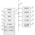
- FIG. 2 is a block diagram showing the configuration of the information processing device 2 in the second embodiment.
- the information processing device 2 includes a calculation device 21 and a storage device 22. Further, the information processing device 2 may include an optical coherence tomography device 100, a communication device 23, an input device 24, and an output device 25. However, the information processing device 2 does not need to include at least one of the optical coherence tomography device 100, the communication device 23, the input device 24, and the output device 25. If the information processing device 2 does not include the optical coherence tomography device 100, the information processing device 2 may transmit and receive information to and from the optical coherence tomography device 100 via the communication device 23.
- the arithmetic device 21, the storage device 22, the optical coherence tomography device 100, the communication device 23, the input device 24, and the output device 25 may be connected via a data bus 26.
- the arithmetic unit 21 is, for example, one of a CPU (Central Processing Unit), a GPU (Graphics Processing Unit), and an FPGA (Field Programmable Gate Array). Contains at least one.
- Arithmetic device 21 reads a computer program.
- the arithmetic device 21 may read a computer program stored in the storage device 22.
- the arithmetic device 21 reads a computer program stored in a computer-readable and non-temporary recording medium using a recording medium reading device (not shown) provided in the information processing device 2 (for example, an input device 24 described later). You can also read it using .
- the arithmetic device 21 may acquire a computer program from a device (not shown) located outside the information processing device 2 via the communication device 23 (or other communication device) (that is, it may not be downloaded). (or may be loaded). The arithmetic device 21 executes the loaded computer program. As a result, within the arithmetic device 21, a logical functional block for executing the operations that the information processing device 2 should perform is realized. That is, the arithmetic device 21 can function as a controller for realizing a logical functional block for executing operations (in other words, processing) that the information processing device 2 should perform.
- FIG. 2 shows an example of logical functional blocks implemented within the arithmetic unit 21 to execute information processing operations.
- the computing device 21 includes a detection unit 211 which is a specific example of a “detection unit”, a detection unit 211 which is a specific example of a “control unit”, and a detection unit 211 which is a specific example of a “transfer unit”.
- a moving unit 213, which is a specific example, is realized.
- the computing device 21 does not need to include the moving unit 213.
- the respective operations of the detection section 211, the control section 212, and the movement section 213 will be described later with reference to FIG. 4.
- the storage device 22 can store desired data.
- the storage device 22 may temporarily store a computer program executed by the arithmetic device 21.
- the storage device 22 may temporarily store data that is temporarily used by the arithmetic device 21 when the arithmetic device 21 is executing a computer program.
- the storage device 22 may store data that the information processing device 2 stores for a long period of time.
- the storage device 22 may include at least one of a RAM (Random Access Memory), a ROM (Read Only Memory), a hard disk device, a magneto-optical disk device, an SSD (Solid State Drive), and a disk array device. good. That is, the storage device 22 may include a non-temporary recording medium.
- the communication device 23 is capable of communicating with devices external to the information processing device 2 via a communication network (not shown).
- the communication device 23 may be a communication interface based on a standard such as Ethernet (registered trademark), Wi-Fi (registered trademark), Bluetooth (registered trademark), or the like.
- the input device 24 is a device that accepts information input to the information processing device 2 from outside the information processing device 2.
- the input device 24 includes an operating device (for example, at least one of a keyboard, a mouse trackball, a touch panel, a pointing device such as a pen tablet, a button, etc.) that can be operated by the operator of the information processing device 2.
- the input device 24 may include a reading device capable of reading information recorded as data on a recording medium that can be externally attached to the information processing device 2.
- the output device 25 is a device that outputs information to the outside of the information processing device 2.
- the output device 25 may output the information as an image.
- the output device 25 may include a display device (so-called display) capable of displaying an image indicating information desired to be output. Examples of display devices include liquid crystal displays, OLED (Organic Light Emitting Diode) displays, and the like.
- the output device 25 may output the information as audio. That is, the output device 25 may include an audio device (so-called speaker) that can output audio.
- the output device 25 may output information on paper. That is, the output device 25 may include a printing device (so-called printer) that can print desired information on paper.
- the input device 24 and the output device 25 may be integrally formed as a touch panel.
- FIG. 2 is an example, and devices other than those shown in FIG. 2 may be added, or some devices may not be provided. Further, some of the devices may be replaced with other devices having similar functions. Furthermore, some of the functions of the second embodiment may be provided by another device via a network. The functions of the second embodiment may be realized by being distributed among a plurality of devices. In this way, the hardware configuration shown in FIG. 2 can be changed as appropriate.
- the optical coherence tomography imaging apparatus 100 irradiates an object with a light beam while scanning in two dimensions, performs optical coherence tomography imaging, and generates three-dimensional brightness data of the object.
- Optical coherence tomography uses interference between object light and reference light to identify the position of the light scattering point in the target where the object light is scattered in the optical axis direction, that is, in the depth direction of the target, and This is a technology that obtains structural data that is spatially resolved in the direction of internal depth.
- Optical coherence tomography technology includes the Time Domain (TD-OCT) method and the Fourier Domain (FD-OCT) method, and the second embodiment employs the FD-OCT method.
- TD-OCT Time Domain
- FD-OCT Fourier Domain
- the second embodiment employs the FD-OCT method.
- the FD-OCT method when an object beam and a reference beam are caused to interfere with each other, an interference light spectrum in a wide wavelength band is measured, and this is Fourier transformed to obtain structural data in the depth direction.
- the coherence tomography apparatus 100 performs optical coherence tomography using the SS-OCT method.
- the optical coherence tomography imaging apparatus 100 performs spatial resolution in the in-plane direction by scanning the irradiation position of the object light in the in-plane direction perpendicular to the depth direction (also referred to as the "Z direction") of the imaging target O. , and it is possible to obtain tomographic structure data spatially resolved in the depth direction, that is, three-dimensional tomographic structure data of the imaging object O.
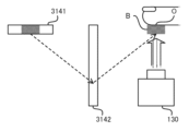
- FIG. 3 is a diagram showing a schematic configuration of an optical coherence tomography apparatus 100 employed in the second embodiment.
- the optical coherence tomography imaging apparatus 100 may image an imaging target O such as a finger of a measurement subject based on a three-dimensional measurement technique of optical coherence tomography and generate three-dimensional brightness data including the inside of the skin.
- the configuration diagram shown in FIG. 3 merely shows an example of an apparatus using optical coherence tomography technology, and an apparatus having a configuration other than that shown in FIG. 3 may be used.
- the optical coherence tomography imaging apparatus 100 may include a light source section 110, a branching/merging section 120, a light irradiation section 130, a mirror section 140, a light receiving section 150, and a signal processing section 160.
- the light irradiation unit 130 may include a scanning mirror and a lens.
- the optical coherence tomography imaging operation of the optical coherence tomography apparatus 100 may be controlled by the arithmetic device 21.
- the light source section 110 may be a laser that emits light while sweeping the wavelength.
- the light source unit 110 may generate and output wavelength-swept optical pulses.
- the light source unit 110 may generate a light pulse by sweeping the wavelength from 1250 nm to 1350 nm for a duration of 5 ⁇ s, for example.
- the branching/merging section 120 may branch the light emitted from the light source section 110 into object light and reference light.
- the object light may be irradiated onto the imaging target O through the light irradiation unit 130.
- the object light scattered in the imaging target O may return to the branching/merging section 120.
- the reference light may be irradiated onto the mirror unit 140 and reflected.
- the reference light reflected by the mirror section 140 may return to the branching/merging section 120.
- the object light scattered by the imaging target O and the reference light reflected by the mirror section 140 may interfere at the branching/merging section 120, and two interference lights may be generated. That is, the intensity ratio of the two interference lights may be determined by the phase difference between the object light and the reference light.
- the light receiving unit 150 may receive two interference lights and output a voltage according to the difference in intensity between the two interference lights.
- the voltage output by the light receiving section 150 may be input to the signal processing section 160.
- the signal processing unit 160 may generate interference light spectrum data based on information regarding a change in the wavelength of the light emitted by the light source unit 110 and information regarding a change in the intensity ratio of two interference lights.
- the signal processing unit 160 may perform Fourier transform on the generated interference light spectrum data to obtain data indicating the intensity of backscattered light (object light) at different depth positions in the depth direction (Z direction).
- the signal processing unit 160 may be supplied with an A-scan trigger signal from the light source unit 110 and may generate an A-scan waveform at predetermined intervals.
- the signal processing unit 160 may generate a waveform indicating the object light backscatter intensity at Nz locations as the A-scan waveform.
- the signal processing unit 160 may control the light irradiation unit 130 according to the A-scan trigger signal supplied from the light source unit 110.
- the light irradiation unit 130 may scan the irradiation position of the object light on the imaging target O.
- the light irradiation unit 130 may move the irradiation position of the object light in the scanning line direction (also referred to as "scanning fast axis direction” and "X direction").
- the signal processing unit 160 may repeatedly perform the A-scan operation for each irradiation position of the object light, and connect the A-scan waveforms for each irradiation position of the object light. Thereby, the signal processing unit 160 can obtain a two-dimensional intensity map of backscattered light (object light) in the scanning line direction (X direction) and depth direction (Z direction) as a tomographic image. .
- the operation of repeatedly performing the A-scan operation while moving in the scanning line direction (scanning fast axis direction, X direction) and connecting the measurement results will be referred to as "B-scan".
- the tomographic image obtained by the B-scan is two-dimensional brightness data that indicates the object light backscatter intensity at Nz ⁇ Nx points.
- the light irradiation unit 130 moves the irradiation position of the object light not only in the scanning line direction (X direction) but also in a direction perpendicular to the scanning line (also referred to as "scan slow axis direction” or "Y direction”). It's okay.
- the signal processing unit 160 may repeatedly perform the B-scan operation and connect the B-scan measurement results. Thereby, the signal processing unit 160 can acquire three-dimensional tomographic structure data.
- C scan the operation of repeatedly performing the B scan operation while moving in the direction perpendicular to the scanning line (Y direction) and connecting the measurement results.
- the tomographic structure data obtained by the C scan is three-dimensional brightness data indicating the object light backscatter intensity at the Nz ⁇ Nx ⁇ Ny point.
- the signal processing unit 160 sends the data after data conversion processing to the arithmetic unit 21 . Note that the operation by the signal processing section 160 may be performed by the arithmetic device 21. [Effects of optical coherence tomography imaging]
- a fingerprint image of the epidermis can be acquired without contact. This prevents the fingertips from coming into contact with a glass plate or the like, which is sanitary. Furthermore, unlike epidermal fingerprint imaging in which a fingerprint image is captured by bringing the fingertip into contact with a glass plate or the like, this method is not affected by deformation during contact. Moreover, a fingerprint image of the dermis can be obtained by optical coherence tomography. That is, since a fingerprint image can be obtained without being affected by the condition of the epidermis, a fingerprint image can be obtained even when it is difficult to read a fingerprint on the epidermis. Furthermore, when the epidermal fingerprint has been altered, it is suitable for detecting the alteration. [2-3: Information processing operation performed by information processing device 2]
- FIG. 4 is a flowchart showing the flow of information processing operations performed by the information processing device 2 in the second embodiment.
- the detection unit 211 detects the inter-object distance between the imaging target O and the light irradiation unit 130 that irradiates light that scans the imaging target O (step S20).
- the detection unit 211 may detect the distance d between the imaging target O and the light irradiation unit 130, as illustrated in FIG.
- the detection unit 211 may detect the distance between objects based on the B-scan results obtained by the optical coherence tomography apparatus 100.
- the inter-object distance may be a distance in the Z direction.
- the detection unit 211 may perform a B-scan of the imaging object O existing at a desired position on the XY plane, and detect the distance between the objects by using analysis of a two-dimensional cross-sectional image obtained by the B-scan.
- the detection unit 211 can detect the distance between the objects without adding a new device to the information processing device 2. . Further, the detection unit 211 can detect the distance between objects while continuing to monitor the imaging object O.
- the moving unit 213 moves the light irradiation unit 130 to a position suitable for scanning the imaging target O based on the distance between the objects (step S21).
- the light irradiation unit 130 may be placed on a vertically movable stage, for example, and configured to be vertically movable.
- the up-down direction may be the above-mentioned Z direction.
- the moving unit 213 may move the light irradiation unit 130 up and down so that the distance between the imaging target O and the light irradiation unit 130 becomes the optimum distance.
- the control unit 212 causes the light irradiation unit 130 to start irradiation of light (step S22).
- the light irradiation unit 130 may irradiate a light beam in the Z direction.
- the light irradiation unit 130 can start irradiation of light in a state where O and the light irradiation unit 130 are in an appropriate positional relationship, and highly accurate optical coherence tomography imaging can be performed.
- a third embodiment of an information processing device, an information processing method, and a recording medium will be described.
- a third embodiment of the information processing apparatus, the information processing method, and the recording medium will be described using an information processing apparatus 3 to which the third embodiment of the information processing apparatus, the information processing method, and the recording medium is applied.
- FIG. 5 is a block diagram showing the configuration of the information processing device 3 in the third embodiment.
- the information processing device 3 in the third embodiment includes an arithmetic device 21 and a storage device 22, similar to the information processing device 2 in the second embodiment. Furthermore, the information processing device 3 may include an optical coherence tomography device 100, a communication device 23, an input device 24, and an output device 25, similar to the information processing device 2 in the second embodiment. However, the information processing device 3 does not need to include the optical coherence tomography device 100 and at least one of the communication device 23, the input device 24, and the output device 25.
- the information processing device 3 in the third embodiment differs from the information processing device 2 in the second embodiment in that the arithmetic device 21 includes an output control unit 314. Other features of the information processing device 3 may be the same as other features of the information processing device 2 in the second embodiment. [3-2: Information processing operation performed by information processing device 3]
- FIG. 6 is a flowchart showing the flow of information processing operations performed by the information processing device 3 in the third embodiment.
- the output control unit 314 outputs guide information that guides the imaging target O to a desired position (step S30).
- the guide information may include at least one of visual information, auditory information, and tactile information.
- the output control unit 314 may control the output device 25 to output the guide information.
- the guide information includes at least visual information, and the visual information may be an image visibly displayed at a desired position.
- the output control unit 314 may display an aerial button B as guide information to lead to a desired position. [3-3: Air button B]
- FIG. 7 is a conceptual diagram of the air button B.
- the information processing device 3 in the third embodiment is provided with an air button display display 3141 and a retroreflector 3142 near the information processing device 3 in order to realize the air button B. You can leave it there.
- the aerial button display 3141 may be a liquid crystal display, an OLED (Organic Light Emitting Diode) display, or the like.
- the retroreflector 3142 may be a member capable of retroreflection.
- the aerial button B may be an image formed in the air by retroreflecting the image displayed by the aerial button display 3141 on the retroreflector 3142.
- the information processing device 3 can form an image in the air by employing the aerial button display 3141 and the retroreflector 3142.
- the aerial button display 3141 and the retroreflector 3142 may be provided depending on the positional relationship with the light irradiation unit 130. By appropriately providing the aerial button display 3141 and the retroreflector 3142, an image can be formed at a desired position.
- the output control unit 314 may display the aerial button B in the air at the optimal position for imaging the imaging target O.
- the output control unit 314 may form an aerial button B above the light irradiation unit 130.
- the aerial button B can be used to follow the finger and guide the finger to a desired position.
- the output control unit 314 may form a button-shaped image as the aerial button B.
- the detection unit 211 detects the distance between the imaging target O and the light irradiation unit 130.
- the output control unit 314 may change at least one of the color and shape of the aerial button B according to the detection result by the detection unit 211. At this time, the color may change as the target position approaches. For example, the output control unit 314 colors the aerial button B blue when the imaging target O does not exist, and colors the aerial button B red and blue when the imaging target O is not in a position suitable for imaging. If it is in a position suitable for imaging, the aerial button B may be colored green. Furthermore, instead of changing the color of the aerial button B in stages, the output control unit 314 may change the color of the aerial button B in a gradation according to the distance between objects.
- the aerial button B may be a three-dimensional image.
- the output control unit 314 may deform the aerial button B according to the detection result, that is, the position of the imaging target O.
- the output control unit 314 may change the shape of the aerial button B so that the button is pressed and becomes concave in accordance with the vertical movement of the imaging target O detected by the detection unit 211.
- the output control unit 314 may deform the aerial button B so that the area where the imaging target O is held up is concave.
- the output control unit 314 may deform the aerial button B to guide the imaging target O to a more appropriate position when the positions in the in-plane directions (XY directions) match.
- the output control unit 314 may guide the imaging target O to an accurate position by having the person to be measured push a button. Further, the output control unit 314 may change the shape of the aerial button B discontinuously or continuously.
- the output control unit 314 may further output at least one of auditory information and tactile information as guide information that leads to a desired position.
- the output control unit 314 may output, as auditory information, for example, a sound whose pitch changes depending on the distance between objects, a sound whose volume changes depending on the distance between objects, or the like. Further, the output control unit 314 may output a predetermined sound effect when the correct position is reached.
- the output control unit 314 may output, as the auditory information, a sound specifically instructing left, right, up, down, etc., for example.
- the output control unit 314 may output, as the tactile information, for example, wind whose direction changes depending on the distance between objects, wind whose strength changes depending on the distance between objects, or the like.
- the output control unit 314 may output, for example, ultrasonic waves whose wavelength changes depending on the distance between objects, as the tactile information.
- the detection unit 211 determines whether the imaging target O exists within a desired position range (step S31). If the imaging target O does not exist within the desired position range (step S31: No), the process moves to step S31.
- the detection unit 211 detects an object between the imaging target O and the light irradiation unit 130 that irradiates light to scan the imaging target O. The distance between them is detected (step S20).
- the moving unit 213 moves the light irradiation unit 130 to a position suitable for scanning the imaging target based on the distance between the objects (step S21).
- the control unit 212 causes the light irradiation unit 130 to start irradiation of light (step S22).
- the positional relationship between the imaging target O and the light irradiation unit 130 is appropriate. That is, in optical coherence tomography, it is preferable that the imaging target O and the light irradiation unit 130 can appropriately move relative to each other.
- the information processing device 3 may move the imaging object O guided by the guide information, or may move the light irradiation unit 130 based on the distance between objects.
- the information processing device 3 adjusts the positional relationship between the imaging target O and the light irradiation unit 130 to be appropriate by performing at least one of the output operation of the output control unit 314 and the movement operation of the movement unit 213. Good too.
- optical coherence tomography can be performed with high precision. That is, it is preferable that the imaging object O and the light irradiation section 130 are located at the same position in a plane in a direction perpendicular to the direction in which the light irradiation section 130 irradiates light.
- the output operation of the output control unit 314 can lead to a positional relationship in which light is irradiated perpendicularly to the imaging target O.
- the information processing device 3 may move the imaging target O guided by the guide information, particularly regarding movement in the XY directions. Moreover, the information processing device 3 may move the light irradiation unit 130 based on the distance between objects, especially regarding movement in the Z direction. [3-4: Technical effects of information processing device 3]
- the information processing device 3 in the third embodiment displays an image that is visibly displayed in a space where no substance exists, so it is possible to guide the imaging target to a desired position in a completely non-contact state. I can do it. Moreover, since the information processing device 3 changes at least one of the color and shape of the image according to the distance between the objects, it can assist in making it easier for the imaging object O to move to an appropriate position.
- the information processing device 3 in the third embodiment guides the imaging target O in the in-plane direction and the distance direction, and further adjusts the distance direction mechanically, so that an appropriate positional relationship can be obtained with high accuracy.
- a fourth embodiment of an information processing device, an information processing method, and a recording medium will be described. Below, a fourth embodiment of the information processing apparatus, the information processing method, and the recording medium will be described using an information processing apparatus 4 to which the fourth embodiment of the information processing apparatus, the information processing method, and the recording medium is applied. .
- the information processing device 4 in the fourth embodiment differs from the information processing device 3 in the third embodiment in the output operation by the output control unit 314. Other features of the information processing device 4 may be the same as other features of the information processing device 3. [4-1: When performing optical coherence tomography imaging of the imaging target O from above]
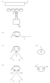
- FIG. 8 is a conceptual diagram when the light irradiation unit 130 performs optical coherence tomography imaging of the imaging target O from above.
- the light irradiation unit 130 may be configured to irradiate light from above onto the imaging target O that exists below the light irradiation unit 130.
- the output control unit 314 may output one guide light beam from the side to the desired position P as guide information for guiding to the desired position.
- the person to be measured may move his or her finger so that the guide light hits the center of the finger pad.
- the output control unit 314 may output two guide light beams to a desired position P as guide information for guiding to a desired position.
- the output control unit 314 may specify one desired position P using two guide light beams.
- FIGS. 8(d) and (f) illustrate how the imaging target O looks when observed from above. As illustrated in FIGS. 8(c) and 8(d), when the imaging target O is located at a desired height, a single point designated by the symbol P is formed by the light beam. On the other hand, as illustrated in FIGS. 8(c) and 8(d), when the imaging target O is located vertically shifted from the desired height, the points formed by the light beam are marked P1 and P2. There will be two with .
- FIG. 9 is a conceptual diagram when the light irradiation unit 130 performs optical coherence tomography imaging of the imaging target O from below. As illustrated in FIG. 9A, the light irradiation unit 130 may be configured to irradiate the imaging target O located above the light irradiation unit 130 with a light beam from below.
- the output control unit 314 may output one guide light beam from the side to the desired position P as guide information for guiding to the desired position.
- the person to be measured may move his or her finger so that the guide light hits the center of the finger pad.
- the output control unit 314 may output two guide light beams to the desired position P as guide information for guiding to the desired position.
- the output control unit 314 may specify one desired position P using two guide light beams.
- FIGS. 9(d) and (f) illustrate how the imaging target O looks when observed from below. As illustrated in FIGS. 9(c) and 9(d), when the imaging target O is located at a desired height, a single point designated by the symbol P is formed by the light beam. On the other hand, as illustrated in FIGS. 9(c) and 9(d), when the imaging target O is located vertically shifted from the desired height, the points formed by the light beam are marked P1 and P2. There will be two with . The person to be measured may move his or her finger so that one point of guide light hits the center of the finger pad. The output control unit 314 may guide the point to a position where exactly one point is formed.
- the information processing device 4 uses a camera (not shown) to image the imaging target O from below, and displays the image on the display D installed with the display surface facing upward. You may display the results.
- the imaging result may be an optical coherence tomographic image.
- Display D may display a finger pad and a beam pointing downward.
- the display D may display the distance between the imaging target O and the light irradiation unit 130.
- the camera may be a stereo camera, and the image displayed on the display D may be a stereo image.
- the output control unit 314 may further output at least one of auditory information and tactile information as guide information that leads to a desired position.
- the output control unit 314 may output, as auditory information, for example, a sound whose pitch changes depending on the distance between objects, a sound whose volume changes depending on the distance between objects, or the like.
- the output control unit 314 may output, as the auditory information, a sound specifically instructing left, right, up, down, etc., for example. Further, the output control unit 314 may output a predetermined sound effect when the correct position is reached.
- the output control unit 314 may output, as the tactile information, for example, wind whose direction changes depending on the distance between objects, wind whose strength changes depending on the distance between objects, or the like.
- the output control unit 314 may output, for example, ultrasonic waves whose wavelength changes depending on the distance between objects, as the tactile information.
- the information processing device 4 in the fourth embodiment guides the imaging target to a desired position using at least one of visual information, auditory information, and tactile information, so that the imaging target O and the light irradiation unit 130 are arranged in an appropriate positional relationship. It is possible to perform coherence tomography imaging in this state.
- a fifth embodiment of an information processing device, an information processing method, and a recording medium will be described.
- a fifth embodiment of the information processing apparatus, the information processing method, and the recording medium will be described using an information processing apparatus 5 to which the fifth embodiment of the information processing apparatus, the information processing method, and the recording medium is applied.
- FIG. 10 is a block diagram showing the configuration of the information processing device 5 in the fifth embodiment.
- the information processing device 5 in the fifth embodiment includes an arithmetic device 21 and a storage device 22, similar to the information processing device 3 in the third embodiment and the information processing device 4 in the fourth embodiment. It is equipped with Furthermore, the information processing device 5 includes an optical coherence tomography device 100, a communication device 23, an input device 24, similar to the information processing device 3 in the third embodiment and the information processing device 4 in the fourth embodiment. It may also include an output device 25. However, the information processing device 5 does not need to include the optical coherence tomography device 100 and at least one of the communication device 23, the input device 24, and the output device 25.
- the output control unit 314 included in the arithmetic device 21 performs the first output control.
- the difference is that it includes a section 5141 and a second output control section 5142.
- Other features of the information processing device 5 may be the same as other features of at least one of the information processing device 3 in the third embodiment and the information processing device 4 in the fourth embodiment.
- FIG. 11 is a flowchart showing the flow of information processing operations performed by the information processing device 5 in the fifth embodiment.
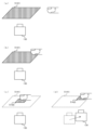
- FIG. 12 is a conceptual diagram showing the flow of information processing operations performed by the information processing device 5 in the fifth embodiment.
- the first output control unit 5141 outputs first guide information that guides the imaging target O to a desired position range (step S50). As illustrated in FIG. 12A, the first output control unit 5141 generates a first guide image as first guide information that directs the measurement subject's attention to move the imaging subject O to a desired location. 5141I may be output.
- the first guide information may be information indicating a range that can be photographed by the light irradiation unit 130.
- the first guide information may be information indicating a movable range of the light irradiation unit 130 in the XY plane.
- the detection unit 211 determines whether the imaging target O exists within a desired position range (step S51). If the imaging target O does not exist within the desired position range (step S51: No), the process moves to step S51.
- the second output control unit 5142 controls the second output control unit 5142 to guide the imaging target O to the desired position.
- Guide information is output (step S52).
- the second output control unit 5142 may output a second guide image 5142I as second guide information that allows the imaging target O to be precisely aligned to a desired position.
- the second guide information may have a U-shape (or U-shape, concave-shape) or the like so as to guide not only the position of the finger but also the direction of the finger.
- the output control unit 314 operates the first output control unit 5141 at the start of operation, and when the imaging target enters a desired position range, the output control unit 314 controls the operation of the first output control unit 5141 to a second output control. The operation may be switched to the operation of the section 5142.
- the detection unit 211 detects the inter-object distance between the imaging target and the light irradiation unit 130 that irradiates light that scans the imaging target (step S20).
- the moving unit 213 moves the light irradiation unit 130 to a position suitable for scanning the imaging target based on the distance between the objects (step S21).
- the control unit 212 causes the light irradiation unit 130 to start irradiation of light (step S22).
- the second output control unit 5142 controls the position of the imaging target O in step S52.
- the moving unit 213 may output the second guide information to a position corresponding to the position of the imaging target O, and move the light irradiation unit 130 to a position corresponding to the position of the imaging target O. That is, the second guide information may be information indicating the range in which the light irradiation unit 130 can photograph after moving in the XY directions.
- the information processing device 5 in the fifth embodiment can make the person to be measured perform rough movements and fine movements by outputting guide information divided into stages. [6: Sixth embodiment]
- a sixth embodiment of an information processing device, an information processing method, and a recording medium will be described. Below, a sixth embodiment of the information processing device, the information processing method, and the recording medium will be described using an information processing device 6 to which the sixth embodiment of the information processing device, the information processing method, and the recording medium is applied. .
- the information processing device 6 in the sixth embodiment differs from the information processing device 2 in the second embodiment to the information processing device 5 in the fifth embodiment in the initial position of the light irradiation unit 130.
- Other features of the information processing device 6 may be the same as at least one other feature of the information processing devices 2 to 5.
- the initial position of the light irradiation unit 130 is determined based on statistical information of the position where the imaging target O was present when the detection unit 211 started operating in the past. For example, the location where the imaging target O is likely to be located may be biased depending on the posture that the person being measured is likely to take.
- the moving unit 213 stores in the storage device 22 the positions where the plurality of measurement subjects first put their fingers over the light irradiation unit 130 and the position of the light irradiation unit 130 when the light irradiation unit 130 starts irradiating light. You may let them.
- the moving unit 213 may move the light irradiating unit 130 in advance to a position that is statistically likely to be held over first before starting the information processing operation.
- the moving unit 213 may determine the initial position of the light irradiation unit 130 based on history information of the position where the person to be measured first placed his or her finger over the light irradiation unit 130 .
- the moving unit 213 may associate the initial position of the light irradiation unit 130 with a time zone or a day of the week.
- the moving unit 213 may determine the initial position according to the day of the week, time of day, or the like. Depending on the day of the week and the time of day, locations where the imaging target is likely to exist are often biased. That is, the method for setting the initial position may be arbitrarily changed depending on the environment in which it is used.
- the information processing device 6 in the sixth embodiment determines the amount of movement of the light irradiation unit 130 by determining the initial position of the light irradiation unit 130 based on the statistical information of the position where the imaging target O existed at the start of the past detection operation. It is possible to reduce the operating load and suppress the operating load. [7: Additional notes]
- Detection means for detecting an inter-object distance between an imaging target and a light irradiation unit that irradiates light that scans the imaging target; and scanning control means for starting the light irradiation by the light irradiation unit when the distance between the objects is a desired distance.
- the information processing device according to supplementary note 1, further comprising a moving unit that moves the light irradiation unit to a position suitable for scanning the imaging target based on the distance between the objects.
- [Additional note 3] further comprising output means for outputting guide information that guides the imaging target to a desired position
- the information processing device according to Supplementary note 1 or 2 wherein the guide information includes at least one of visual information, auditory information, and tactile information.
- the visual information is an image visibly displayed at the desired position.
- the output means changes at least one of the color and shape of the image depending on the distance between objects.
- the output means is first output means for outputting first guide information that guides the imaging target to a desired position range; a second output means for outputting second guide information that guides the imaging target to the desired position;
- the first output means operates,
- the information processing device according to any one of Supplementary Notes 3 to 5, wherein when the imaging target enters the desired position range, the operation of the first output means is switched to the operation of the second output means.
- the information processing device according to any one of Supplementary Notes 1 to 6, wherein the initial position of the light irradiation unit is determined based on statistical information of the position where the imaging target was present when the detection unit started operating in the past.
Abstract
An information processing device 1 comprises a detection unit 11 that detects an object-to-object distance between an object to be photographed and a light emission unit that emits light for scanning the object to be photographed, and a control unit 12 that starts emission of light by the light emission unit if the object-to-object distance is equal to an intended distance.
Description
この開示は、情報処理装置、情報処理方法、及び、記録媒体の技術分野に関する。
This disclosure relates to the technical field of information processing devices, information processing methods, and recording media.
生体情報を含む身体の部位に対して、可視光線によりセンサとの位置を示すパターンを投影することで、利用者が身体をセンサのガイドに触れることなく、センサに対して決められた位置に適切な位置に身体を止める、非接触型のガイドが特許文献1に記載されている。光源から出た光を、少なくとも一方と他方に分割し、分割された一方の光を、光入出部から測定対象に向けて照射し、測定対象からの反射光を、光干渉断層ヘッドが光入出部から測定光として取り込み、光干渉断層ヘッドの光入出部を、測定対象を中心として、回動可能に支持して、正確な断層画像を取得する技術が特許文献2に記載されている。管状体の管内径に変化が生じた場合に、管状体の管内径の変化に追従して、その都度、撮像部とレーザ光照射部との間の距離を調整し、環状レーザ光を確実に撮像する技術が特許文献3に記載されている。光干渉断層ユニットにより撮影された眼底の断層画像を小区画に分割し、分割した小区画ごとに代表値を求めて、該求めた代表値の内選択された代表値を断層像の品質を示す画質パラメータとして算出し、算出した断層像の画質パラメータを表示器に表示する技術が特許文献4に記載されている。波長掃引レーザ光源から出射された光を物体光と参照光に分岐する分岐合流器と、表面に厚さが変化する構造が形成された透明基板を透過して測定対象物に照射され、測定対象物から散乱された物体光と参照光との干渉光の強度比の変化に関する情報を生成するバランス型受光器と、干渉光の強度比の変化に関する情報に基づいて測定対象物の深さ方向の構造データを取得する制御部と、を備え、制御部は、物体光の照射位置を移動させながら取得した複数の深さ方向の構造データを、透明基板の構造の位置を基準として接続する情報処理装置が特許文献5に記載されている。
By projecting a pattern showing the position of the sensor using visible light on the part of the body that contains biological information, the user can properly position the body in relation to the sensor without touching the sensor's guide. Patent Document 1 describes a non-contact type guide that stops the body in a certain position. The light emitted from the light source is divided into at least one and the other, one of the divided lights is irradiated from the light input/output section toward the measurement object, and the optical coherence tomography head converts the reflected light from the measurement object into the optical input/output section. Patent Document 2 describes a technique for acquiring an accurate tomographic image by taking in measurement light from an optical coherence tomography head as measurement light and supporting the light input/output part of an optical coherence tomography head so as to be rotatable around the measurement target. When a change occurs in the inner diameter of the tubular body, the distance between the imaging unit and the laser beam irradiation unit is adjusted each time to follow the change in the inner diameter of the tubular body, and the annular laser beam is reliably emitted. A technology for imaging is described in Patent Document 3. A tomographic image of the fundus taken by an optical coherence tomography unit is divided into small sections, a representative value is obtained for each divided small section, and a representative value selected from among the obtained representative values is used to indicate the quality of the tomographic image. Patent Document 4 describes a technique of calculating image quality parameters of a tomographic image and displaying the calculated image quality parameters of a tomographic image on a display. The light emitted from the wavelength-swept laser light source is transmitted through a splitting/merging device that splits the light into an object beam and a reference beam, and a transparent substrate on which a structure with varying thickness is formed, and is irradiated onto the measurement target. A balanced photodetector that generates information about the change in the intensity ratio of the interference light between the object light and the reference light scattered from the object, and a balance type receiver that generates information about the change in the intensity ratio of the interference light between the object light and the reference light scattered from the object, and detects the depth direction of the measurement target based on the information about the change in the intensity ratio of the interference light. a control unit that acquires structural data; the control unit performs information processing that connects a plurality of pieces of structural data in the depth direction acquired while moving the irradiation position of the object light with reference to the position of the structure of the transparent substrate; A device is described in US Pat.
この開示は、先行技術文献に記載された技術の改良を目的とする情報処理装置、情報処理方法、及び、記録媒体を提供することを課題とする。
An object of this disclosure is to provide an information processing device, an information processing method, and a recording medium that aim to improve the techniques described in prior art documents.
情報処理装置の一の態様は、撮像対象と、当該撮像対象を走査する光を照射する光照射部との間の対象間距離を検出する検出手段と、前記対象間距離が所望の距離の場合、前記光照射部による前記光の照射を開始する走査制御手段とを備える。
One aspect of the information processing device includes a detection means for detecting an inter-object distance between an imaging object and a light irradiation unit that irradiates light that scans the imaging object, and when the inter-object distance is a desired distance. , and scan control means for starting irradiation of the light by the light irradiation section.
情報処理方法の一の態様は、撮像対象と、当該撮像対象を走査する光を照射する光照射部との間の対象間距離を検出し、前記対象間距離が所望の距離の場合、前記光照射部による前記光の照射を開始する。
One aspect of the information processing method is to detect an inter-object distance between an imaging object and a light irradiation unit that irradiates light that scans the imaging object, and when the inter-object distance is a desired distance, the light The irradiation unit starts irradiating the light.
記録媒体の一の態様は、コンピューターに、撮像対象と、当該撮像対象を走査する光を照射する光照射部との間の対象間距離を検出し、前記対象間距離が所望の距離の場合、前記光照射部による前記光の照射を開始する情報処理方法を実行させるためのコンピュータプログラムが記録されている。
One aspect of the recording medium is to have a computer detect an inter-object distance between an imaging object and a light irradiation unit that irradiates light that scans the imaging object, and when the inter-object distance is a desired distance, A computer program for executing an information processing method for starting irradiation of the light by the light irradiation unit is recorded.
以下、図面を参照しながら、情報処理装置、情報処理方法、及び、記録媒体の実施形態について説明する。
[1:第1実施形態] Embodiments of an information processing device, an information processing method, and a recording medium will be described below with reference to the drawings.
[1: First embodiment]
[1:第1実施形態] Embodiments of an information processing device, an information processing method, and a recording medium will be described below with reference to the drawings.
[1: First embodiment]
情報処理装置、情報処理方法、及び、記録媒体の第1実施形態について説明する。以下では、情報処理装置、情報処理方法、及び記録媒体の第1実施形態が適用された情報処理装置1を用いて、情報処理装置、情報処理方法、及び記録媒体の第1実施形態について説明する。
[1-1:情報処理装置1の構成] A first embodiment of an information processing device, an information processing method, and a recording medium will be described. Below, a first embodiment of an information processing device, an information processing method, and a recording medium will be described using aninformation processing device 1 to which the first embodiment of the information processing device, information processing method, and recording medium is applied. .
[1-1: Configuration of information processing device 1]
[1-1:情報処理装置1の構成] A first embodiment of an information processing device, an information processing method, and a recording medium will be described. Below, a first embodiment of an information processing device, an information processing method, and a recording medium will be described using an
[1-1: Configuration of information processing device 1]
図1を参照しながら、第1実施形態における情報処理装置1の構成について説明する。図1は、第1実施形態における情報処理装置1の構成を示すブロック図である。
The configuration of the information processing device 1 in the first embodiment will be described with reference to FIG. 1. FIG. 1 is a block diagram showing the configuration of an information processing device 1 in the first embodiment.
図1に示すように、情報処理装置1は、検出部11と、制御部12とを備える。検出部11は、撮像対象と、当該撮像対象を走査する光を照射する光照射部との間の対象間距離を検出する。制御部12は、対象間距離が所望の距離の場合、光照射部による光の照射を開始する。
[1-2:情報処理装置1の技術的効果] As shown in FIG. 1, theinformation processing device 1 includes a detection section 11 and a control section 12. The detection unit 11 detects an inter-object distance between an imaging target and a light irradiation unit that irradiates light that scans the imaging target. When the distance between the objects is a desired distance, the control unit 12 starts irradiation of light by the light irradiation unit.
[1-2: Technical effects of information processing device 1]
[1-2:情報処理装置1の技術的効果] As shown in FIG. 1, the
[1-2: Technical effects of information processing device 1]
第1実施形態における情報処理装置1は、対象間距離が所望の距離の場合、すなわち、撮像対象と光照射部とが適切な位置関係にある場合に光照射部が光の照射を開始するので、高精度の光干渉断層撮像をすることができる。
[2:第2実施形態] In theinformation processing device 1 according to the first embodiment, the light irradiation unit starts emitting light when the distance between objects is a desired distance, that is, when the imaging target and the light irradiation unit are in an appropriate positional relationship. , it is possible to perform highly accurate optical coherence tomography imaging.
[2: Second embodiment]
[2:第2実施形態] In the
[2: Second embodiment]
情報処理装置、情報処理方法、及び、記録媒体の第2実施形態について説明する。以下では、情報処理装置、情報処理方法、及び記録媒体の第2実施形態が適用された情報処理装置2を用いて、情報処理装置、情報処理方法、及び記録媒体の第2実施形態について説明する。
[2-1:情報処理装置2の構成] A second embodiment of an information processing device, an information processing method, and a recording medium will be described. In the following, a second embodiment of the information processing apparatus, the information processing method, and the recording medium will be described using aninformation processing apparatus 2 to which the second embodiment of the information processing apparatus, the information processing method, and the recording medium is applied. .
[2-1: Configuration of information processing device 2]
[2-1:情報処理装置2の構成] A second embodiment of an information processing device, an information processing method, and a recording medium will be described. In the following, a second embodiment of the information processing apparatus, the information processing method, and the recording medium will be described using an
[2-1: Configuration of information processing device 2]
図2を参照しながら、第2実施形態における情報処理装置2の構成について説明する。図2は、第2実施形態における情報処理装置2の構成を示すブロック図である。
The configuration of the information processing device 2 in the second embodiment will be described with reference to FIG. 2. FIG. 2 is a block diagram showing the configuration of the information processing device 2 in the second embodiment.
図2に示すように、情報処理装置2は、演算装置21と、記憶装置22とを備えている。更に、情報処理装置2は、光干渉断層撮像装置100と、通信装置23と、入力装置24と、出力装置25とを備えていてもよい。但し、情報処理装置2は、光干渉断層撮像装置100、通信装置23、入力装置24及び出力装置25のうちの少なくとも1つを備えていなくてもよい。情報処理装置2が、光干渉断層撮像装置100を備えない場合、情報処理装置2は、光干渉断層撮像装置100と、通信装置23を介して情報の送受信を行っていもよい。演算装置21と、記憶装置22と、光干渉断層撮像装置100と、通信装置23と、入力装置24と、出力装置25とは、データバス26を介して接続されていてもよい。
As shown in FIG. 2, the information processing device 2 includes a calculation device 21 and a storage device 22. Further, the information processing device 2 may include an optical coherence tomography device 100, a communication device 23, an input device 24, and an output device 25. However, the information processing device 2 does not need to include at least one of the optical coherence tomography device 100, the communication device 23, the input device 24, and the output device 25. If the information processing device 2 does not include the optical coherence tomography device 100, the information processing device 2 may transmit and receive information to and from the optical coherence tomography device 100 via the communication device 23. The arithmetic device 21, the storage device 22, the optical coherence tomography device 100, the communication device 23, the input device 24, and the output device 25 may be connected via a data bus 26.
演算装置21は、例えば、CPU(Central Processing Unit)、GPU(Graphics Proecssing Unit)及びFPGA(Field Programmable Gate Array)のうちの少なくとも1つを含む。演算装置21は、コンピュータプログラムを読み込む。例えば、演算装置21は、記憶装置22が記憶しているコンピュータプログラムを読み込んでもよい。例えば、演算装置21は、コンピュータで読み取り可能であって且つ一時的でない記録媒体が記憶しているコンピュータプログラムを、情報処理装置2が備える図示しない記録媒体読み取り装置(例えば、後述する入力装置24)を用いて読み込んでもよい。演算装置21は、通信装置23(或いは、その他の通信装置)を介して、情報処理装置2の外部に配置される不図示の装置からコンピュータプログラムを取得してもよい(つまり、ダウンロードしてもよい又は読み込んでもよい)。演算装置21は、読み込んだコンピュータプログラムを実行する。その結果、演算装置21内には、情報処理装置2が行うべき動作を実行するための論理的な機能ブロックが実現される。つまり、演算装置21は、情報処理装置2が行うべき動作(言い換えれば、処理)を実行するための論理的な機能ブロックを実現するためのコントローラとして機能可能である。
The arithmetic unit 21 is, for example, one of a CPU (Central Processing Unit), a GPU (Graphics Processing Unit), and an FPGA (Field Programmable Gate Array). Contains at least one. Arithmetic device 21 reads a computer program. For example, the arithmetic device 21 may read a computer program stored in the storage device 22. For example, the arithmetic device 21 reads a computer program stored in a computer-readable and non-temporary recording medium using a recording medium reading device (not shown) provided in the information processing device 2 (for example, an input device 24 described later). You can also read it using . The arithmetic device 21 may acquire a computer program from a device (not shown) located outside the information processing device 2 via the communication device 23 (or other communication device) (that is, it may not be downloaded). (or may be loaded). The arithmetic device 21 executes the loaded computer program. As a result, within the arithmetic device 21, a logical functional block for executing the operations that the information processing device 2 should perform is realized. That is, the arithmetic device 21 can function as a controller for realizing a logical functional block for executing operations (in other words, processing) that the information processing device 2 should perform.
図2には、情報処理動作を実行するために演算装置21内に実現される論理的な機能ブロックの一例が示されている。図2に示すように、演算装置21内には、「検出手段」の一具体例である検出部211と、「制御手段」の一具体例である検出部211と、「移動手段」の一具体例である移動部213とが実現される。但し、演算装置21は、移動部213を備えていなくてもよい。検出部211、制御部212、及び移動部213の夫々の動作については、図4を参照して後述する。
FIG. 2 shows an example of logical functional blocks implemented within the arithmetic unit 21 to execute information processing operations. As shown in FIG. 2, the computing device 21 includes a detection unit 211 which is a specific example of a “detection unit”, a detection unit 211 which is a specific example of a “control unit”, and a detection unit 211 which is a specific example of a “transfer unit”. A moving unit 213, which is a specific example, is realized. However, the computing device 21 does not need to include the moving unit 213. The respective operations of the detection section 211, the control section 212, and the movement section 213 will be described later with reference to FIG. 4.
記憶装置22は、所望のデータを記憶可能である。例えば、記憶装置22は、演算装置21が実行するコンピュータプログラムを一時的に記憶していてもよい。記憶装置22は、演算装置21がコンピュータプログラムを実行している場合に演算装置21が一時的に使用するデータを一時的に記憶してもよい。記憶装置22は、情報処理装置2が長期的に保存するデータを記憶してもよい。尚、記憶装置22は、RAM(Random Access Memory)、ROM(Read Only Memory)、ハードディスク装置、光磁気ディスク装置、SSD(Solid State Drive)及びディスクアレイ装置のうちの少なくとも1つを含んでいてもよい。つまり、記憶装置22は、一時的でない記録媒体を含んでいてもよい。
The storage device 22 can store desired data. For example, the storage device 22 may temporarily store a computer program executed by the arithmetic device 21. The storage device 22 may temporarily store data that is temporarily used by the arithmetic device 21 when the arithmetic device 21 is executing a computer program. The storage device 22 may store data that the information processing device 2 stores for a long period of time. Note that the storage device 22 may include at least one of a RAM (Random Access Memory), a ROM (Read Only Memory), a hard disk device, a magneto-optical disk device, an SSD (Solid State Drive), and a disk array device. good. That is, the storage device 22 may include a non-temporary recording medium.
通信装置23は、不図示の通信ネットワークを介して、情報処理装置2の外部の装置と通信可能である。通信装置23は、イーサネット(登録商標)、Wi-Fi(登録商標)、Bluetooth(登録商標)等の規格に基づく通信インターフェースであってもよい。
The communication device 23 is capable of communicating with devices external to the information processing device 2 via a communication network (not shown). The communication device 23 may be a communication interface based on a standard such as Ethernet (registered trademark), Wi-Fi (registered trademark), Bluetooth (registered trademark), or the like.
入力装置24は、情報処理装置2の外部からの情報処理装置2に対する情報の入力を受け付ける装置である。例えば、入力装置24は、情報処理装置2のオペレータが操作可能な操作装置(例えば、キーボード、マウストラックボール、タッチパネル、ペンタブレット等のポインティングデバイス、ボタン等のうちの少なくとも1つ)を含んでいてもよい。例えば、入力装置24は情報処理装置2に対して外付け可能な記録媒体にデータとして記録されている情報を読み取り可能な読取装置を含んでいてもよい。
The input device 24 is a device that accepts information input to the information processing device 2 from outside the information processing device 2. For example, the input device 24 includes an operating device (for example, at least one of a keyboard, a mouse trackball, a touch panel, a pointing device such as a pen tablet, a button, etc.) that can be operated by the operator of the information processing device 2. Good too. For example, the input device 24 may include a reading device capable of reading information recorded as data on a recording medium that can be externally attached to the information processing device 2.
出力装置25は、情報処理装置2の外部に対して情報を出力する装置である。例えば、出力装置25は、情報を画像として出力してもよい。つまり、出力装置25は、出力したい情報を示す画像を表示可能な表示装置(いわゆる、ディスプレイ)を含んでいてもよい。表示装置の例としては、液晶ディスプレイ、OLED(Organic Light Emitting Diode)ディスプレイ等が挙げられる。例えば、出力装置25は、情報を音声として出力してもよい。つまり、出力装置25は、音声を出力可能な音声装置(いわゆる、スピーカ)を含んでいてもよい。例えば、出力装置25は、紙面に情報を出力してもよい。つまり、出力装置25は、紙面に所望の情報を印刷可能な印刷装置(いわゆる、プリンタ)を含んでいてもよい。また、入力装置24及び出力装置25は、タッチパネルとして一体に形成されていてもよい。
The output device 25 is a device that outputs information to the outside of the information processing device 2. For example, the output device 25 may output the information as an image. That is, the output device 25 may include a display device (so-called display) capable of displaying an image indicating information desired to be output. Examples of display devices include liquid crystal displays, OLED (Organic Light Emitting Diode) displays, and the like. For example, the output device 25 may output the information as audio. That is, the output device 25 may include an audio device (so-called speaker) that can output audio. For example, the output device 25 may output information on paper. That is, the output device 25 may include a printing device (so-called printer) that can print desired information on paper. Further, the input device 24 and the output device 25 may be integrally formed as a touch panel.
なお、図2に示されているハードウェア構成は一例であり、図2に示されている装置以外の装置が追加されていてもよく、一部の装置が設けられていなくてもよい。また、一部の装置が同様の機能を有する別の装置に置換されていてもよい。また、第2実施形態の一部の機能がネットワークを介して他の装置により提供されてもよい。第2実施形態の機能が複数の装置に分散されて実現されてもよい。このように、図2に示されているハードウェア構成は適宜変更可能である。
[2-2:光干渉断層撮像装置100] Note that the hardware configuration shown in FIG. 2 is an example, and devices other than those shown in FIG. 2 may be added, or some devices may not be provided. Further, some of the devices may be replaced with other devices having similar functions. Furthermore, some of the functions of the second embodiment may be provided by another device via a network. The functions of the second embodiment may be realized by being distributed among a plurality of devices. In this way, the hardware configuration shown in FIG. 2 can be changed as appropriate.
[2-2: Optical coherence tomography imaging device 100]
光干渉断層撮像装置100は、対象に対して光ビームを二次元走査しながら照射し、光干渉断層撮像を行い、対象の三次元輝度データを生成する。
The optical coherence tomography imaging apparatus 100 irradiates an object with a light beam while scanning in two dimensions, performs optical coherence tomography imaging, and generates three-dimensional brightness data of the object.
光干渉断層撮像は、物体光と参照光との干渉を利用することにより、対象において物体光が散乱される光散乱点の光軸方向、すなわち対象の深さ方向における位置を特定し、対象の内部の深さ方向に空間分解した構造データを得る技術である。光干渉断層技術には、Time Domain(TD-OCT)方式、Fourier Domain(FD-OCT)方式があるが、第2実施形態ではFD-OCT方式を採用する。FD-OCT方式では、物体光と参照光とを干渉させる際に、広い波長帯域の干渉光スペクトルを測定し、これをフーリエ変換することで深さ方向の構造データを得る。干渉光スペクトルを得る方式として、分光器を用いるSpectral Domain(SD-OCT)方式と、波長を掃引する光源を用いるSwept Source(SS-OCT)方式とがあるが、第2実施形態において採用する光干渉断層撮像装置100は、SS-OCT方式において、光干渉断層撮像を行う。
Optical coherence tomography uses interference between object light and reference light to identify the position of the light scattering point in the target where the object light is scattered in the optical axis direction, that is, in the depth direction of the target, and This is a technology that obtains structural data that is spatially resolved in the direction of internal depth. Optical coherence tomography technology includes the Time Domain (TD-OCT) method and the Fourier Domain (FD-OCT) method, and the second embodiment employs the FD-OCT method. In the FD-OCT method, when an object beam and a reference beam are caused to interfere with each other, an interference light spectrum in a wide wavelength band is measured, and this is Fourier transformed to obtain structural data in the depth direction. As a method for obtaining an interference light spectrum, there are a Spectral Domain (SD-OCT) method that uses a spectroscope and a Swept Source (SS-OCT) method that uses a light source that sweeps the wavelength. The coherence tomography apparatus 100 performs optical coherence tomography using the SS-OCT method.
光干渉断層撮像装置100は、撮像対象Oの深さ方向(「Z方向」とも称する)に垂直な面内方向において、物体光の照射位置を走査することにより、当該面内方向に空間分解し、且つ、深さ方向に空間分解した断層構造データ、すなわち、撮像対象Oの三次元の断層構造データを得ることができる。
The optical coherence tomography imaging apparatus 100 performs spatial resolution in the in-plane direction by scanning the irradiation position of the object light in the in-plane direction perpendicular to the depth direction (also referred to as the "Z direction") of the imaging target O. , and it is possible to obtain tomographic structure data spatially resolved in the depth direction, that is, three-dimensional tomographic structure data of the imaging object O.
図3は、第2実施形態において採用する光干渉断層撮像装置100の概略構成を示す図である。光干渉断層撮像装置100は、光干渉断層撮像の三次元測定技術に基づいて測定対象者の指等の撮像対象Oを撮像し、皮膚の内部を含む三次元輝度データを生成してもよい。なお、図3に示す構成図は、光干渉断層撮像技術を用いた装置の一例を示すものに過ぎず、図3に示した構成以外の構成の装置であってもよい。
FIG. 3 is a diagram showing a schematic configuration of an optical coherence tomography apparatus 100 employed in the second embodiment. The optical coherence tomography imaging apparatus 100 may image an imaging target O such as a finger of a measurement subject based on a three-dimensional measurement technique of optical coherence tomography and generate three-dimensional brightness data including the inside of the skin. Note that the configuration diagram shown in FIG. 3 merely shows an example of an apparatus using optical coherence tomography technology, and an apparatus having a configuration other than that shown in FIG. 3 may be used.
図3に示すように、光干渉断層撮像装置100は、光源部110、分岐合流部120、光照射部130、ミラー部140、受光部150、及び信号処理部160を含んでいてもよい。光照射部130は、走査ミラーとレンズとを含んでいてもよい。光干渉断層撮像装置100の光干渉断層撮像動作は、演算装置21に制御されていてもよい。
As shown in FIG. 3, the optical coherence tomography imaging apparatus 100 may include a light source section 110, a branching/merging section 120, a light irradiation section 130, a mirror section 140, a light receiving section 150, and a signal processing section 160. The light irradiation unit 130 may include a scanning mirror and a lens. The optical coherence tomography imaging operation of the optical coherence tomography apparatus 100 may be controlled by the arithmetic device 21.
光源部110は、波長を掃引しながら光を出射するレーザであってもよい。光源部110は、波長掃引された光パルスを生成して出力してもよい。光源部110は、例えば、持続時間5μsの間に、波長が1250nmから1350nmまで掃引して光パルスを生成してもよい。
The light source section 110 may be a laser that emits light while sweeping the wavelength. The light source unit 110 may generate and output wavelength-swept optical pulses. The light source unit 110 may generate a light pulse by sweeping the wavelength from 1250 nm to 1350 nm for a duration of 5 μs, for example.
分岐合流部120は、光源部110から出射された光を、物体光と参照光とに分岐してもよい。物体光は、光照射部130を経て、撮像対象Oに照射されてもよい。撮像対象Oにおいて散乱された物体光は、分岐合流部120に戻ってもよい。一方、参照光は、ミラー部140に照射されて反射されてもよい。ミラー部140において反射された参照光は、分岐合流部120に戻ってもよい。撮像対象Oに散乱された物体光と、ミラー部140に反射された参照光とは、分岐合流部120において干渉し、2つの干渉光が生成されてもよい。すなわち、2つの干渉光の強度比は、物体光と参照光との位相差によって決定されてもよい。
The branching/merging section 120 may branch the light emitted from the light source section 110 into object light and reference light. The object light may be irradiated onto the imaging target O through the light irradiation unit 130. The object light scattered in the imaging target O may return to the branching/merging section 120. On the other hand, the reference light may be irradiated onto the mirror unit 140 and reflected. The reference light reflected by the mirror section 140 may return to the branching/merging section 120. The object light scattered by the imaging target O and the reference light reflected by the mirror section 140 may interfere at the branching/merging section 120, and two interference lights may be generated. That is, the intensity ratio of the two interference lights may be determined by the phase difference between the object light and the reference light.
受光部150は、2つの干渉光が入力され、2つの干渉光の強度差に応じた電圧を出力してもよい。受光部150が出力した電圧は、信号処理部160へ入力されてもよい。
[Aスキャン] Thelight receiving unit 150 may receive two interference lights and output a voltage according to the difference in intensity between the two interference lights. The voltage output by the light receiving section 150 may be input to the signal processing section 160.
[A scan]
[Aスキャン] The
[A scan]
信号処理部160は、光源部110が出射する光の波長変化に関する情報、及び、2つの干渉光の強度比の変化に関する情報に基づいて、干渉光スペクトルデータを生成してもよい。信号処理部160は、生成した干渉光スペクトルデータをフーリエ変換して、深さ方向(Z方向)の異なる深さ位置における後方散乱光(物体光)の強度を示すデータを取得してもよい。
The signal processing unit 160 may generate interference light spectrum data based on information regarding a change in the wavelength of the light emitted by the light source unit 110 and information regarding a change in the intensity ratio of two interference lights. The signal processing unit 160 may perform Fourier transform on the generated interference light spectrum data to obtain data indicating the intensity of backscattered light (object light) at different depth positions in the depth direction (Z direction).
以下、撮像対象Oにおける物体光の照射位置の深さ方向(Z方向)の後方散乱光(物体光)の強度を示すデータを取得する動作を、「Aスキャン」と称する。信号処理部160は、光源部110からAスキャントリガ信号が供給され、所定の周期毎にAスキャン波形を生成してもよい。信号処理部160は、Aスキャン波形として、Nz箇所の物体光後方散乱強度を示す波形を生成してもよい。
[Bスキャン] Hereinafter, the operation of acquiring data indicating the intensity of backscattered light (object light) in the depth direction (Z direction) of the irradiation position of the object light in the imaging target O will be referred to as "A scan". Thesignal processing unit 160 may be supplied with an A-scan trigger signal from the light source unit 110 and may generate an A-scan waveform at predetermined intervals. The signal processing unit 160 may generate a waveform indicating the object light backscatter intensity at Nz locations as the A-scan waveform.
[B scan]
[Bスキャン] Hereinafter, the operation of acquiring data indicating the intensity of backscattered light (object light) in the depth direction (Z direction) of the irradiation position of the object light in the imaging target O will be referred to as "A scan". The
[B scan]
信号処理部160は、光源部110から供給されたAスキャントリガ信号に応じて、光照射部130を制御してもよい。光照射部130は、撮像対象O上における物体光の照射位置を走査してもよい。光照射部130は、物体光の照射位置を走査線方向(「走査の速軸方向」、及び「X方向」とも称する)に移動させてもよい。
The signal processing unit 160 may control the light irradiation unit 130 according to the A-scan trigger signal supplied from the light source unit 110. The light irradiation unit 130 may scan the irradiation position of the object light on the imaging target O. The light irradiation unit 130 may move the irradiation position of the object light in the scanning line direction (also referred to as "scanning fast axis direction" and "X direction").
信号処理部160は、物体光の照射位置毎にAスキャン動作を繰り返し行い、物体光の照射位置毎のAスキャン波形を接続してもよい。これにより、信号処理部160は、走査線方向(X方向)と深さ方向(Z方向)との二次元の後方散乱光(物体光)の強度のマップを、断層画像として取得することができる。以下、走査線方向(走査の速軸方向、X方向)に移動しながら、Aスキャン動作を繰り返し行って、その測定結果を接続する動作を、「Bスキャン」と称する。Bスキャン毎の物体光の照射位置を、Nx箇所とすると、Bスキャンによる断層画像は、Nz×Nx点の物体光後方散乱強度を示す二次元輝度データである。
[Cスキャン] Thesignal processing unit 160 may repeatedly perform the A-scan operation for each irradiation position of the object light, and connect the A-scan waveforms for each irradiation position of the object light. Thereby, the signal processing unit 160 can obtain a two-dimensional intensity map of backscattered light (object light) in the scanning line direction (X direction) and depth direction (Z direction) as a tomographic image. . Hereinafter, the operation of repeatedly performing the A-scan operation while moving in the scanning line direction (scanning fast axis direction, X direction) and connecting the measurement results will be referred to as "B-scan". Assuming that the object light irradiation positions for each B-scan are Nx locations, the tomographic image obtained by the B-scan is two-dimensional brightness data that indicates the object light backscatter intensity at Nz×Nx points.
[C scan]
[Cスキャン] The
[C scan]
光照射部130は、物体光の照射位置を、走査線方向(X方向)だけでなく、走査線に垂直な方向(「走査の遅軸方向」、「Y方向」ともよぶ)にも移動させてもよい。信号処理部160は、Bスキャン動作を繰り返し行い、Bスキャン測定結果を接続してもよい。これにより、信号処理部160は、三次元の断層構造データを取得することができる。以下、走査線に垂直な方向(Y方向)に移動しながら、Bスキャン動作を繰り返し行って、その測定結果を接続する動作を、「Cスキャン」と称する。Cスキャン毎に実施するBスキャン回数を、Ny回とした場合、Cスキャンによって得られる断層構造データは、Nz×Nx×Ny点の物体光後方散乱強度を示す三次元輝度データである。
The light irradiation unit 130 moves the irradiation position of the object light not only in the scanning line direction (X direction) but also in a direction perpendicular to the scanning line (also referred to as "scan slow axis direction" or "Y direction"). It's okay. The signal processing unit 160 may repeatedly perform the B-scan operation and connect the B-scan measurement results. Thereby, the signal processing unit 160 can acquire three-dimensional tomographic structure data. Hereinafter, the operation of repeatedly performing the B scan operation while moving in the direction perpendicular to the scanning line (Y direction) and connecting the measurement results will be referred to as "C scan". When the number of B scans performed for each C scan is Ny times, the tomographic structure data obtained by the C scan is three-dimensional brightness data indicating the object light backscatter intensity at the Nz×Nx×Ny point.
信号処理部160は、データ化処理後のデータを、演算装置21に送る。なお、信号処理部160による動作は、演算装置21で行ってもよい。
[光干渉断層撮像の効果] Thesignal processing unit 160 sends the data after data conversion processing to the arithmetic unit 21 . Note that the operation by the signal processing section 160 may be performed by the arithmetic device 21.
[Effects of optical coherence tomography imaging]
[光干渉断層撮像の効果] The
[Effects of optical coherence tomography imaging]
光干渉断層撮像によれば、非接触で表皮の指紋画像を取得することができる。これにより、指先をガラス板等に接触させないので、衛生的である。また、指先をガラス板等に接触させて指紋画像を撮像する表皮指紋撮像とは異なり、接触の際の変形の影響を受けることがない。また、光干渉断層撮像により、真皮の指紋画像を取得することができる。すなわち、表皮の状態に影響を受けずに、指紋画像を取得することができるので、表皮の指紋読取が困難な場合にも指紋画像を取得することができる。さらに、表皮指紋が改変されている場合において、改変の見破りに好適である。
[2-3:情報処理装置2が行う情報処理動作] According to optical coherence tomography, a fingerprint image of the epidermis can be acquired without contact. This prevents the fingertips from coming into contact with a glass plate or the like, which is sanitary. Furthermore, unlike epidermal fingerprint imaging in which a fingerprint image is captured by bringing the fingertip into contact with a glass plate or the like, this method is not affected by deformation during contact. Moreover, a fingerprint image of the dermis can be obtained by optical coherence tomography. That is, since a fingerprint image can be obtained without being affected by the condition of the epidermis, a fingerprint image can be obtained even when it is difficult to read a fingerprint on the epidermis. Furthermore, when the epidermal fingerprint has been altered, it is suitable for detecting the alteration.
[2-3: Information processing operation performed by information processing device 2]
図4を参照して、第2実施形態における情報処理装置2が行う状処理動作の流れを説明する。図4は、第2実施形態における情報処理装置2の行う情報処理動作の流れを示すフローチャートである。
With reference to FIG. 4, the flow of the processing operation performed by the information processing device 2 in the second embodiment will be described. FIG. 4 is a flowchart showing the flow of information processing operations performed by the information processing device 2 in the second embodiment.
図4に示すように、検出部211は、撮像対象Oと、当該撮像対象Oを走査する光を照射する光照射部130との間の対象間距離を検出する(ステップS20)。検出部211は、図3に例示するように、撮像対象Oと光照射部130との間の距離dを検出してもよい。検出部211は、光干渉断層撮像装置100によるBスキャン結果に基づいて、対象間距離を検出してもよい。対象間距離は、上記Z方向における距離であってもよい。検出部211は、XY平面上において、所望の位置に存在する撮像対象OをBスキャンし、当該Bスキャンにより得られる二次元断面画像の解析を利用して、対象間距離を検出してもよい。光干渉断層撮像装置100によるBスキャン結果に基づいて、対象間距離を検出した場合、情報処理装置2に新たなデバイスを付加することなく、検出部211は対象間距離を検出をすることができる。また、検出部211は、撮像対象Oをモニタし続けた状態で、対象間距離を検出することができる。
As shown in FIG. 4, the detection unit 211 detects the inter-object distance between the imaging target O and the light irradiation unit 130 that irradiates light that scans the imaging target O (step S20). The detection unit 211 may detect the distance d between the imaging target O and the light irradiation unit 130, as illustrated in FIG. The detection unit 211 may detect the distance between objects based on the B-scan results obtained by the optical coherence tomography apparatus 100. The inter-object distance may be a distance in the Z direction. The detection unit 211 may perform a B-scan of the imaging object O existing at a desired position on the XY plane, and detect the distance between the objects by using analysis of a two-dimensional cross-sectional image obtained by the B-scan. . When the distance between objects is detected based on the B-scan result by the optical coherence tomography apparatus 100, the detection unit 211 can detect the distance between the objects without adding a new device to the information processing device 2. . Further, the detection unit 211 can detect the distance between objects while continuing to monitor the imaging object O.
移動部213は、対象間距離に基づき、光照射部130を、撮像対象Oの走査に適した位置に移動させる(ステップS21)。光照射部130は、例えば上下動ステージに載置され、上下動可能に構成されていてもよい。上下方向は、上記Z方向であってもよい。移動部213は、撮像対象Oと光照射部130との間の距離が最適距離になるように、光照射部130を上下動させてもよい。
The moving unit 213 moves the light irradiation unit 130 to a position suitable for scanning the imaging target O based on the distance between the objects (step S21). The light irradiation unit 130 may be placed on a vertically movable stage, for example, and configured to be vertically movable. The up-down direction may be the above-mentioned Z direction. The moving unit 213 may move the light irradiation unit 130 up and down so that the distance between the imaging target O and the light irradiation unit 130 becomes the optimum distance.
制御部212は、対象間距離が所望の距離の場合、光照射部130による光の照射を開始する(ステップS22)。光照射部130は、Z方向に向けて光ビームを照射してもよい。
[2-4:情報処理装置2の技術的効果] When the distance between the objects is a desired distance, thecontrol unit 212 causes the light irradiation unit 130 to start irradiation of light (step S22). The light irradiation unit 130 may irradiate a light beam in the Z direction.
[2-4: Technical effects of information processing device 2]
[2-4:情報処理装置2の技術的効果] When the distance between the objects is a desired distance, the
[2-4: Technical effects of information processing device 2]
第2実施形態における情報処理装置2は、光照射部130を、撮像対象Oの走査に適した位置に移動させるので、撮像対象O自身が適切な位置に移動しきれない場合にも、撮像対象Oと光照射部130とが適切な位置関係にある状態で光照射部130が光の照射を開始することができ、高精度の光干渉断層撮像をすることができる。
[3:第3実施形態] Since theinformation processing device 2 in the second embodiment moves the light irradiation unit 130 to a position suitable for scanning the imaging target O, even if the imaging target O itself cannot be moved to an appropriate position, The light irradiation unit 130 can start irradiation of light in a state where O and the light irradiation unit 130 are in an appropriate positional relationship, and highly accurate optical coherence tomography imaging can be performed.
[3: Third embodiment]
[3:第3実施形態] Since the
[3: Third embodiment]
情報処理装置、情報処理方法、及び、記録媒体の第3実施形態について説明する。以下では、情報処理装置、情報処理方法、及び記録媒体の第3実施形態が適用された情報処理装置3を用いて、情報処理装置、情報処理方法、及び記録媒体の第3実施形態について説明する。
[3-1:情報処理装置3の構成] A third embodiment of an information processing device, an information processing method, and a recording medium will be described. Below, a third embodiment of the information processing apparatus, the information processing method, and the recording medium will be described using aninformation processing apparatus 3 to which the third embodiment of the information processing apparatus, the information processing method, and the recording medium is applied. .
[3-1: Configuration of information processing device 3]
[3-1:情報処理装置3の構成] A third embodiment of an information processing device, an information processing method, and a recording medium will be described. Below, a third embodiment of the information processing apparatus, the information processing method, and the recording medium will be described using an
[3-1: Configuration of information processing device 3]
図5を参照しながら、第3実施形態における情報処理装置3の構成について説明する。図5は、第3実施形態における情報処理装置3の構成を示すブロック図である。
The configuration of the information processing device 3 in the third embodiment will be described with reference to FIG. 5. FIG. 5 is a block diagram showing the configuration of the information processing device 3 in the third embodiment.
図5に示すように、第3実施形態における情報処理装置3は、第2実施形態における情報処理装置2と同様に、演算装置21と、記憶装置22とを備えている。更に、情報処理装置3は、第2実施形態における情報処理装置2と同様に、光干渉断層撮像装置100と、通信装置23と、入力装置24と、出力装置25とを備えていてもよい。但し、情報処理装置3は、光干渉断層撮像装置100と、通信装置23、入力装置24及び出力装置25のうちの少なくとも1つを備えていなくてもよい。第3実施形態における情報処理装置3は、第2実施形態における情報処理装置2と比較して、演算装置21が出力制御部314を備える点で異なる。情報処理装置3のその他の特徴は、第2実施形態における情報処理装置2のその他の特徴と同一であってもよい。
[3-2:情報処理装置3が行う情報処理動作] As shown in FIG. 5, theinformation processing device 3 in the third embodiment includes an arithmetic device 21 and a storage device 22, similar to the information processing device 2 in the second embodiment. Furthermore, the information processing device 3 may include an optical coherence tomography device 100, a communication device 23, an input device 24, and an output device 25, similar to the information processing device 2 in the second embodiment. However, the information processing device 3 does not need to include the optical coherence tomography device 100 and at least one of the communication device 23, the input device 24, and the output device 25. The information processing device 3 in the third embodiment differs from the information processing device 2 in the second embodiment in that the arithmetic device 21 includes an output control unit 314. Other features of the information processing device 3 may be the same as other features of the information processing device 2 in the second embodiment.
[3-2: Information processing operation performed by information processing device 3]
[3-2:情報処理装置3が行う情報処理動作] As shown in FIG. 5, the
[3-2: Information processing operation performed by information processing device 3]
図6を参照して、第3実施形態における情報処理装置3が行う状処理動作の流れを説明する。図6は、第3実施形態における情報処理装置3の行う情報処理動作の流れを示すフローチャートである。
With reference to FIG. 6, the flow of the processing operation performed by the information processing device 3 in the third embodiment will be described. FIG. 6 is a flowchart showing the flow of information processing operations performed by the information processing device 3 in the third embodiment.
図6に示すように、出力制御部314は、撮像対象Oを、所望の位置に導くガイド情報を出力する(ステップS30)。ガイド情報は、視覚情報、聴覚情報、及び触覚情報の少なくとも1つを含んでいてもよい。出力制御部314は、出力装置25を制御して、ガイド情報を出力させてもよい。第3実施形態において、ガイド情報は、少なくとも視覚情報を含んでおり、視覚情報は、所望の位置に視認可能に表される像であってよい。出力制御部314は、所望の位置に導くガイド情報として、空中ボタンBを表示させてもよい。
[3-3:空中ボタンB] As shown in FIG. 6, theoutput control unit 314 outputs guide information that guides the imaging target O to a desired position (step S30). The guide information may include at least one of visual information, auditory information, and tactile information. The output control unit 314 may control the output device 25 to output the guide information. In the third embodiment, the guide information includes at least visual information, and the visual information may be an image visibly displayed at a desired position. The output control unit 314 may display an aerial button B as guide information to lead to a desired position.
[3-3: Air button B]
[3-3:空中ボタンB] As shown in FIG. 6, the
[3-3: Air button B]
図7は、空中ボタンBの概念図である。図7に示すように、第3実施形態における情報処理装置3は、空中ボタンBを実現するために、情報処理装置3の近傍に空中ボタン表示用ディスプレイ3141、及び再帰性反射板3142が設けられていてもよい。空中ボタン表示用ディスプレイ3141は、液晶ディスプレイ、OLED(Organic Light Emitting Diode)ディスプレイ等であってもよい。再帰性反射板3142は、再帰性反射が可能な部材であってもよい。
FIG. 7 is a conceptual diagram of the air button B. As shown in FIG. 7, the information processing device 3 in the third embodiment is provided with an air button display display 3141 and a retroreflector 3142 near the information processing device 3 in order to realize the air button B. You can leave it there. The aerial button display 3141 may be a liquid crystal display, an OLED (Organic Light Emitting Diode) display, or the like. The retroreflector 3142 may be a member capable of retroreflection.
空中ボタンBは、空中ボタン表示用ディスプレイ3141が表示する画像が、再帰性反射板3142に再帰性反射されて、空中に結像された像であってもよい。情報処理装置3は、空中ボタン表示用ディスプレイ3141、及び再帰性反射板3142を採用することで、像を空中に形成することができる。
The aerial button B may be an image formed in the air by retroreflecting the image displayed by the aerial button display 3141 on the retroreflector 3142. The information processing device 3 can form an image in the air by employing the aerial button display 3141 and the retroreflector 3142.
空中ボタン表示用ディスプレイ3141、及び再帰性反射板3142は、光照射部130との位置関係に応じて設けられていてもよい。空中ボタン表示用ディスプレイ3141、及び再帰性反射板3142を適切に設けることにより、所望の位置に像を結像させることができる。出力制御部314は、撮像対象Oを撮像するのに最適な位置に、空中ボタンBを空中に表示させてもよい。出力制御部314は、光照射部130の上部に空中ボタンBを形成してもよい。空中ボタンBは、指を追従させ、指を所望の位置に誘導するために用いることができる。出力制御部314は、空中ボタンBとしてボタン状の像を形成してもよい。
The aerial button display 3141 and the retroreflector 3142 may be provided depending on the positional relationship with the light irradiation unit 130. By appropriately providing the aerial button display 3141 and the retroreflector 3142, an image can be formed at a desired position. The output control unit 314 may display the aerial button B in the air at the optimal position for imaging the imaging target O. The output control unit 314 may form an aerial button B above the light irradiation unit 130. The aerial button B can be used to follow the finger and guide the finger to a desired position. The output control unit 314 may form a button-shaped image as the aerial button B.
検出部211は、撮像対象Oと光照射部130との対象間距離を検出している。出力制御部314は、検出部211による検出結果に応じて、空中ボタンBの色彩、及び形状の少なくとも一方を変化させてもよい。このとき、目標位置に近づくにつれ、色を変化させてもよい。例えば、出力制御部314は、撮像対象Oが存在しない状態では空中ボタンBを青く着色し、撮像対象Oが撮像に適した位置にない場合は空中ボタンBを赤青く着色し、撮像対象Oが撮像に適した位置にある場合は空中ボタンBを緑に着色してもよい。また、出力制御部314は、空中ボタンBの色を段階的に色を変えるのではなく、対象間距離に応じたグラデーション変化をさせてもよい。
The detection unit 211 detects the distance between the imaging target O and the light irradiation unit 130. The output control unit 314 may change at least one of the color and shape of the aerial button B according to the detection result by the detection unit 211. At this time, the color may change as the target position approaches. For example, the output control unit 314 colors the aerial button B blue when the imaging target O does not exist, and colors the aerial button B red and blue when the imaging target O is not in a position suitable for imaging. If it is in a position suitable for imaging, the aerial button B may be colored green. Furthermore, instead of changing the color of the aerial button B in stages, the output control unit 314 may change the color of the aerial button B in a gradation according to the distance between objects.
空中ボタンBは、立体像であってもよい。出力制御部314は、検出結果、すなわち撮像対象Oの位置に応じて、空中ボタンBを変形させてもよい。出力制御部314は、検出部211の検出する撮像対象Oの上下方向の動きに応じて、ボタンが押されて凹んだように空中ボタンBの形状を変形させてもよい。出力制御部314は、撮像対象Oがかざされた場所が凹むように空中ボタンBを変形させてもよい。出力制御部314は、面内方向(XY方向)における位置が合った場合に、空中ボタンBを変形させて、撮像対象Oをより適切な位置に誘導してもよい。出力制御部314は、測定対象者にボタンを押し込む動作をさせることにより、撮像対象Oを正確な位置に誘導してもよい。また、出力制御部314は、空中ボタンBの形状を不連続に変化させてもよく、連続的に変化させてもよい。
The aerial button B may be a three-dimensional image. The output control unit 314 may deform the aerial button B according to the detection result, that is, the position of the imaging target O. The output control unit 314 may change the shape of the aerial button B so that the button is pressed and becomes concave in accordance with the vertical movement of the imaging target O detected by the detection unit 211. The output control unit 314 may deform the aerial button B so that the area where the imaging target O is held up is concave. The output control unit 314 may deform the aerial button B to guide the imaging target O to a more appropriate position when the positions in the in-plane directions (XY directions) match. The output control unit 314 may guide the imaging target O to an accurate position by having the person to be measured push a button. Further, the output control unit 314 may change the shape of the aerial button B discontinuously or continuously.
出力制御部314は、所望の位置に導くガイド情報として、さらに聴覚情報、及び触覚情報の少なくとも1方を出力してもよい。出力制御部314は、聴覚情報として、例えば、対象間距離に応じて音程の高低が変化する音、対象間距離に応じて音量が変化する音等を出力してもよい。また、出力制御部314は、正確な位置に到達した場合に、所定の効果音を出力してもよい。出力制御部314は、聴覚情報として、例えば、具体的に左右上下等を指示する音声を出力してもよい。出力制御部314は、触覚情報として、例えば、対象間距離に応じて向きが変化する風、対象間距離に応じて強さが変化する風等を出力してもよい。出力制御部314は、触覚情報として、例えば、対象間距離に応じて波長が変化する超音波等を出力してもよい。
The output control unit 314 may further output at least one of auditory information and tactile information as guide information that leads to a desired position. The output control unit 314 may output, as auditory information, for example, a sound whose pitch changes depending on the distance between objects, a sound whose volume changes depending on the distance between objects, or the like. Further, the output control unit 314 may output a predetermined sound effect when the correct position is reached. The output control unit 314 may output, as the auditory information, a sound specifically instructing left, right, up, down, etc., for example. The output control unit 314 may output, as the tactile information, for example, wind whose direction changes depending on the distance between objects, wind whose strength changes depending on the distance between objects, or the like. The output control unit 314 may output, for example, ultrasonic waves whose wavelength changes depending on the distance between objects, as the tactile information.
図6に示すように、検出部211は、撮像対象Oが所望の位置範囲内に存在するか否かを判定する(ステップS31)。撮像対象Oが所望の位置範囲内に存在しない場合(ステップS31:No)、ステップS31に移行する。
As shown in FIG. 6, the detection unit 211 determines whether the imaging target O exists within a desired position range (step S31). If the imaging target O does not exist within the desired position range (step S31: No), the process moves to step S31.
撮像対象Oが所望の位置範囲内に存在する場合(ステップS31:Yes)、検出部211は、撮像対象Oと、当該撮像対象Oを走査する光を照射する光照射部130との間の対象間距離を検出する(ステップS20)。移動部213は、対象間距離に基づき、光照射部130を、撮像対象の走査に適した位置に移動させる(ステップS21)。制御部212は、対象間距離が所望の距離の場合、光照射部130による光の照射を開始する(ステップS22)。
If the imaging target O exists within the desired position range (step S31: Yes), the detection unit 211 detects an object between the imaging target O and the light irradiation unit 130 that irradiates light to scan the imaging target O. The distance between them is detected (step S20). The moving unit 213 moves the light irradiation unit 130 to a position suitable for scanning the imaging target based on the distance between the objects (step S21). When the distance between the objects is a desired distance, the control unit 212 causes the light irradiation unit 130 to start irradiation of light (step S22).
光干渉断層撮像においては、撮像対象Oと光照射部130との位置関係が適切であることが好ましい。すなわち、光干渉断層撮像においては、撮像対象Oと光照射部130とが適切に相対移動できることが好ましい。情報処理装置3は、ガイド情報に導かせて撮像対象Oを移動させてもよいし、対象間距離に基づき光照射部130を移動させてもよい。情報処理装置3は、出力制御部314の出力動作、及び移動部213による移動動作の少なくとも一方を実施することにより、撮像対象Oと光照射部130と位置関係が適切になるように調整してもよい。
In optical coherence tomography, it is preferable that the positional relationship between the imaging target O and the light irradiation unit 130 is appropriate. That is, in optical coherence tomography, it is preferable that the imaging target O and the light irradiation unit 130 can appropriately move relative to each other. The information processing device 3 may move the imaging object O guided by the guide information, or may move the light irradiation unit 130 based on the distance between objects. The information processing device 3 adjusts the positional relationship between the imaging target O and the light irradiation unit 130 to be appropriate by performing at least one of the output operation of the output control unit 314 and the movement operation of the movement unit 213. Good too.
光照射部130が撮像対象Oに対して光を垂直に照射することで、精度よく光干渉断層撮像をすることができる。すなわち、撮像対象Oと光照射部130との、光照射部130が光を照射する方向に対して垂直な方向の面内における位置は、同じであると好適である。出力制御部314の出力動作により、光が撮像対象Oに対して垂直に照射される位置関係に導くことができる。
By the light irradiation unit 130 perpendicularly irradiating light onto the imaging target O, optical coherence tomography can be performed with high precision. That is, it is preferable that the imaging object O and the light irradiation section 130 are located at the same position in a plane in a direction perpendicular to the direction in which the light irradiation section 130 irradiates light. The output operation of the output control unit 314 can lead to a positional relationship in which light is irradiated perpendicularly to the imaging target O.
また、人間の視覚(又は知覚距離、感覚距離)は、距離方向(Z方向)の精度が、面内方向(XY方向)と比較して低い場合が多い。そこで、情報処理装置3は、特にXY方向における移動に関しては、ガイド情報に導かせて撮像対象Oを移動させてもよい。また、情報処理装置3は、特にZ方向における移動に関しては、対象間距離に基づき、光照射部130を移動させてもよい。
[3-4:情報処理装置3の技術的効果] Furthermore, human vision (or perceptual distance, sensory distance) often has lower accuracy in the distance direction (Z direction) than in the in-plane direction (XY direction). Therefore, theinformation processing device 3 may move the imaging target O guided by the guide information, particularly regarding movement in the XY directions. Moreover, the information processing device 3 may move the light irradiation unit 130 based on the distance between objects, especially regarding movement in the Z direction.
[3-4: Technical effects of information processing device 3]
[3-4:情報処理装置3の技術的効果] Furthermore, human vision (or perceptual distance, sensory distance) often has lower accuracy in the distance direction (Z direction) than in the in-plane direction (XY direction). Therefore, the
[3-4: Technical effects of information processing device 3]
不特定多数の人物が触れる物を直接触れることに抵抗感を抱く場面は多く存在する。また、接触操作により接触部に残った指紋が盗難されるような社会課題も存在する。このような衛生面への配慮やセキュリティリスクの低減などを目的に、各種入力デバイスにおいて非接触操作が求められている。しかしながら、非接触操作は、接触操作と比較して、適切な位置関係で操作させるように制御することが難しい。
There are many situations where people feel reluctant to directly touch something that is touched by a large number of unspecified people. Furthermore, there is also a social issue in which fingerprints left on the contact portion due to contact operations are stolen. For the purpose of such hygiene considerations and security risk reduction, contactless operation is required for various input devices. However, compared to contact operation, non-contact operation is difficult to control so that the operation is performed in an appropriate positional relationship.
これに対し、第3実施形態における情報処理装置3は、実体の存在しない空間において、視認可能に表される像を表示するので、完全に非接触な状態で撮像対象を所望の位置に導くことができる。また、情報処理装置3は、対象間距離に応じて、像の色彩、及び形状の少なくとも一方を変化させるので、撮像対象Oが適切な位置に移動し易くすることを補助することができる。
On the other hand, the information processing device 3 in the third embodiment displays an image that is visibly displayed in a space where no substance exists, so it is possible to guide the imaging target to a desired position in a completely non-contact state. I can do it. Moreover, since the information processing device 3 changes at least one of the color and shape of the image according to the distance between the objects, it can assist in making it easier for the imaging object O to move to an appropriate position.
第3実施形態における情報処理装置3は、撮像対象Oを面内方向、及び距離方向に誘導し、さらに、距離方向は機械により調整するので、精度よく適切な位置関係を得ることができる。
[4:第4実施形態] Theinformation processing device 3 in the third embodiment guides the imaging target O in the in-plane direction and the distance direction, and further adjusts the distance direction mechanically, so that an appropriate positional relationship can be obtained with high accuracy.
[4: Fourth embodiment]
[4:第4実施形態] The
[4: Fourth embodiment]
情報処理装置、情報処理方法、及び、記録媒体の第4実施形態について説明する。以下では、情報処理装置、情報処理方法、及び記録媒体の第4実施形態が適用された情報処理装置4を用いて、情報処理装置、情報処理方法、及び記録媒体の第4実施形態について説明する。
A fourth embodiment of an information processing device, an information processing method, and a recording medium will be described. Below, a fourth embodiment of the information processing apparatus, the information processing method, and the recording medium will be described using an information processing apparatus 4 to which the fourth embodiment of the information processing apparatus, the information processing method, and the recording medium is applied. .
第4実施形態における情報処理装置4は、第3実施形態における情報処理装置3と比較して、出力制御部314による出力動作が異なる。情報処理装置4のその他の特徴は、情報処理装置3のその他の特徴と同一であってもよい。
[4-1:上部から撮像対象Oを光干渉断層撮像する場合] The information processing device 4 in the fourth embodiment differs from theinformation processing device 3 in the third embodiment in the output operation by the output control unit 314. Other features of the information processing device 4 may be the same as other features of the information processing device 3.
[4-1: When performing optical coherence tomography imaging of the imaging target O from above]
[4-1:上部から撮像対象Oを光干渉断層撮像する場合] The information processing device 4 in the fourth embodiment differs from the
[4-1: When performing optical coherence tomography imaging of the imaging target O from above]
図8は、光照射部130が、上部から撮像対象Oを光干渉断層撮像する場合の概念図である。図8(a)に例示するように、光照射部130は、光照射部130より下に存在する撮像対象Oに、上から光を照射するように構成されていてもよい。
FIG. 8 is a conceptual diagram when the light irradiation unit 130 performs optical coherence tomography imaging of the imaging target O from above. As illustrated in FIG. 8A, the light irradiation unit 130 may be configured to irradiate light from above onto the imaging target O that exists below the light irradiation unit 130.
図8(b)に例示するように、出力制御部314は、所望の位置に導くガイド情報として、所望の位置Pに横から1本のガイド光ビームを出力してもよい。測定対象者は、指腹の中央にガイド光が当たるように、指を移動させてもよい。
As illustrated in FIG. 8(b), the output control unit 314 may output one guide light beam from the side to the desired position P as guide information for guiding to the desired position. The person to be measured may move his or her finger so that the guide light hits the center of the finger pad.
図8(c)及び(e)に例示するように、出力制御部314は、所望の位置に導くガイド情報として、所望の位置Pに2本のガイド光ビームを出力してもよい。出力制御部314は、2本のガイド光ビームにより、1点の所望の位置Pを特定してもよい。図8(d)及び(f)は、撮像対象Oを上から観察した場合の見え方を例示している。図8(c)及び(d)に例示するように、所望の高さに撮像対象Oが位置する場合、光ビームにより形成される点は、符号Pが付された1つである。これに対し、図8(c)及び(d)に例示するように、所望の高さから上下方向にずれるて撮像対象Oが位置する場合、光ビームにより形成される点は、符号P1及びP2が付された2つになる。測定対象者は、指腹の中央に1点のガイド光が当たるように、指を移動させてもよい。出力制御部314は、点がぴったり1つになる位置に撮像対象Oを誘導してもよい。
[4-2:下部から撮像対象Oを光干渉断層撮像する場合]
図9は、光照射部130が、下部から撮像対象Oを光干渉断層撮像する場合の概念図である。図9(a)に例示するように、光照射部130は、光照射部130より上に存在する撮像対象Oに、下から光ビームを照射するように構成されていてもよい。 As illustrated in FIGS. 8(c) and 8(e), theoutput control unit 314 may output two guide light beams to a desired position P as guide information for guiding to a desired position. The output control unit 314 may specify one desired position P using two guide light beams. FIGS. 8(d) and (f) illustrate how the imaging target O looks when observed from above. As illustrated in FIGS. 8(c) and 8(d), when the imaging target O is located at a desired height, a single point designated by the symbol P is formed by the light beam. On the other hand, as illustrated in FIGS. 8(c) and 8(d), when the imaging target O is located vertically shifted from the desired height, the points formed by the light beam are marked P1 and P2. There will be two with . The person to be measured may move his or her finger so that one point of guide light hits the center of the finger pad. The output control unit 314 may guide the imaging target O to a position where exactly one point is formed.
[4-2: When performing optical coherence tomography imaging of the imaging target O from the bottom]
FIG. 9 is a conceptual diagram when thelight irradiation unit 130 performs optical coherence tomography imaging of the imaging target O from below. As illustrated in FIG. 9A, the light irradiation unit 130 may be configured to irradiate the imaging target O located above the light irradiation unit 130 with a light beam from below.
[4-2:下部から撮像対象Oを光干渉断層撮像する場合]
図9は、光照射部130が、下部から撮像対象Oを光干渉断層撮像する場合の概念図である。図9(a)に例示するように、光照射部130は、光照射部130より上に存在する撮像対象Oに、下から光ビームを照射するように構成されていてもよい。 As illustrated in FIGS. 8(c) and 8(e), the
[4-2: When performing optical coherence tomography imaging of the imaging target O from the bottom]
FIG. 9 is a conceptual diagram when the
図9(b)に例示するように、出力制御部314は、所望の位置に導くガイド情報として、所望の位置Pに横から1本のガイド光ビームを出力してもよい。測定対象者は、指腹の中央にガイド光が当たるように、指を移動させてもよい。
As illustrated in FIG. 9(b), the output control unit 314 may output one guide light beam from the side to the desired position P as guide information for guiding to the desired position. The person to be measured may move his or her finger so that the guide light hits the center of the finger pad.
図9(c)及び(e)に例示するように、出力制御部314は、所望の位置に導くガイド情報として、所望の位置Pに2本のガイド光ビームを出力してもよい。出力制御部314は、2本のガイド光ビームにより、1点の所望の位置Pを特定してもよい。図9(d)及び(f)は、撮像対象Oを下から観察した場合の見え方を例示している。図9(c)及び(d)に例示するように、所望の高さに撮像対象Oが位置する場合、光ビームにより形成される点は、符号Pが付された1つである。これに対し、図9(c)及び(d)に例示するように、所望の高さから上下方向にずれるて撮像対象Oが位置する場合、光ビームにより形成される点は、符号P1及びP2が付された2つになる。測定対象者は、指腹の中央に1点のガイド光が当たるように、指を移動させてもよい。出力制御部314は、点がぴったり1つになる位置に誘導してもよい。
As illustrated in FIGS. 9(c) and 9(e), the output control unit 314 may output two guide light beams to the desired position P as guide information for guiding to the desired position. The output control unit 314 may specify one desired position P using two guide light beams. FIGS. 9(d) and (f) illustrate how the imaging target O looks when observed from below. As illustrated in FIGS. 9(c) and 9(d), when the imaging target O is located at a desired height, a single point designated by the symbol P is formed by the light beam. On the other hand, as illustrated in FIGS. 9(c) and 9(d), when the imaging target O is located vertically shifted from the desired height, the points formed by the light beam are marked P1 and P2. There will be two with . The person to be measured may move his or her finger so that one point of guide light hits the center of the finger pad. The output control unit 314 may guide the point to a position where exactly one point is formed.
また、図9(a)に例示するように、情報処理装置4は、図示を省略するカメラにより撮像対象Oを下から撮像し、表示面が上に向いて設置されるディスプレイDにカメラによる撮像結果を表示してもよい。撮像結果は、光干渉断層画像であってもよい。ディスプレイDは、下に向けた指腹とビームとを表示してもよい。ディスプレイDは、撮像対象Oと光照射部130との対象間距離を表示してもよい。なお、カメラはステレオカメラであってもよく、ディスプレイDに表示される画像はステレオ画像であってもよい。
Further, as illustrated in FIG. 9A, the information processing device 4 uses a camera (not shown) to image the imaging target O from below, and displays the image on the display D installed with the display surface facing upward. You may display the results. The imaging result may be an optical coherence tomographic image. Display D may display a finger pad and a beam pointing downward. The display D may display the distance between the imaging target O and the light irradiation unit 130. Note that the camera may be a stereo camera, and the image displayed on the display D may be a stereo image.
出力制御部314は、所望の位置に導くガイド情報として、さらに聴覚情報、及び触覚情報の少なくとも1方を出力してもよい。出力制御部314は、聴覚情報として、例えば、対象間距離に応じて音程の高低が変化する音、対象間距離に応じて音量が変化する音等を出力してもよい。出力制御部314は、聴覚情報として、例えば、具体的に左右上下等を指示する音声を出力してもよい。また、出力制御部314は、正確な位置に到達した場合に、所定の効果音を出力してもよい。出力制御部314は、触覚情報として、例えば、対象間距離に応じて向きが変化する風、対象間距離に応じて強さが変化する風等を出力してもよい。出力制御部314は、触覚情報として、例えば、対象間距離に応じて波長が変化する超音波等を出力してもよい。
The output control unit 314 may further output at least one of auditory information and tactile information as guide information that leads to a desired position. The output control unit 314 may output, as auditory information, for example, a sound whose pitch changes depending on the distance between objects, a sound whose volume changes depending on the distance between objects, or the like. The output control unit 314 may output, as the auditory information, a sound specifically instructing left, right, up, down, etc., for example. Further, the output control unit 314 may output a predetermined sound effect when the correct position is reached. The output control unit 314 may output, as the tactile information, for example, wind whose direction changes depending on the distance between objects, wind whose strength changes depending on the distance between objects, or the like. The output control unit 314 may output, for example, ultrasonic waves whose wavelength changes depending on the distance between objects, as the tactile information.
なお、第3実施形態、及び第4実施形態では、出力制御部314が所望の位置に導くガイド情報として視覚情報を出力する場合を説明したが、出力制御部314は、ガイド情報として視覚情報を出力せず、聴覚情報、及び触覚情報の少なくとも1方を出力してもよい。
[4-3:情報処理装置4の技術的効果] Note that in the third and fourth embodiments, a case has been described in which theoutput control unit 314 outputs visual information as guide information that leads to a desired position, but the output control unit 314 outputs visual information as guide information. Instead, at least one of auditory information and tactile information may be output.
[4-3: Technical effects of information processing device 4]
[4-3:情報処理装置4の技術的効果] Note that in the third and fourth embodiments, a case has been described in which the
[4-3: Technical effects of information processing device 4]
第4実施形態における情報処理装置4は、視覚情報、聴覚情報、及び触覚情報の少なくとも1つにより、撮像対象を所望の位置に導くので、撮像対象Oと光照射部130とを適切な位置関係にした状態で干渉断層撮像をすることができる。
[5:第5実施形態] The information processing device 4 in the fourth embodiment guides the imaging target to a desired position using at least one of visual information, auditory information, and tactile information, so that the imaging target O and thelight irradiation unit 130 are arranged in an appropriate positional relationship. It is possible to perform coherence tomography imaging in this state.
[5: Fifth embodiment]
[5:第5実施形態] The information processing device 4 in the fourth embodiment guides the imaging target to a desired position using at least one of visual information, auditory information, and tactile information, so that the imaging target O and the
[5: Fifth embodiment]
情報処理装置、情報処理方法、及び、記録媒体の第5実施形態について説明する。以下では、情報処理装置、情報処理方法、及び記録媒体の第5実施形態が適用された情報処理装置5を用いて、情報処理装置、情報処理方法、及び記録媒体の第5実施形態について説明する。
[5-1:情報処理装置5の構成] A fifth embodiment of an information processing device, an information processing method, and a recording medium will be described. In the following, a fifth embodiment of the information processing apparatus, the information processing method, and the recording medium will be described using aninformation processing apparatus 5 to which the fifth embodiment of the information processing apparatus, the information processing method, and the recording medium is applied. .
[5-1: Configuration of information processing device 5]
[5-1:情報処理装置5の構成] A fifth embodiment of an information processing device, an information processing method, and a recording medium will be described. In the following, a fifth embodiment of the information processing apparatus, the information processing method, and the recording medium will be described using an
[5-1: Configuration of information processing device 5]
図10を参照しながら、第5実施形態における情報処理装置5の構成について説明する。図10は、第5実施形態における情報処理装置5の構成を示すブロック図である。
The configuration of the information processing device 5 in the fifth embodiment will be described with reference to FIG. 10. FIG. 10 is a block diagram showing the configuration of the information processing device 5 in the fifth embodiment.
図10に示すように、第5実施形態における情報処理装置5は、第3実施形態における情報処理装置3、及び第4実施形態における情報処理装置4と同様に、演算装置21と、記憶装置22とを備えている。更に、情報処理装置5は、第3実施形態における情報処理装置3、及び第4実施形態における情報処理装置4と同様に、光干渉断層撮像装置100と、通信装置23と、入力装置24と、出力装置25とを備えていてもよい。但し、情報処理装置5は、光干渉断層撮像装置100と、通信装置23、入力装置24及び出力装置25のうちの少なくとも1つを備えていなくてもよい。第5実施形態における情報処理装置5は、第3実施形態における情報処理装置3、及び第4実施形態における情報処理装置4と比較して、演算装置21が備える出力制御部314が第1出力制御部5141及び第2出力制御部5142を含む点で異なる。情報処理装置5のその他の特徴は、第3実施形態における情報処理装置3、及び第4実施形態における情報処理装置4の少なくとも一方のその他の特徴と同一であってもよい。
[5-2:情報処理装置5の行う情報処理動作] As shown in FIG. 10, theinformation processing device 5 in the fifth embodiment includes an arithmetic device 21 and a storage device 22, similar to the information processing device 3 in the third embodiment and the information processing device 4 in the fourth embodiment. It is equipped with Furthermore, the information processing device 5 includes an optical coherence tomography device 100, a communication device 23, an input device 24, similar to the information processing device 3 in the third embodiment and the information processing device 4 in the fourth embodiment. It may also include an output device 25. However, the information processing device 5 does not need to include the optical coherence tomography device 100 and at least one of the communication device 23, the input device 24, and the output device 25. In the information processing device 5 in the fifth embodiment, compared to the information processing device 3 in the third embodiment and the information processing device 4 in the fourth embodiment, the output control unit 314 included in the arithmetic device 21 performs the first output control. The difference is that it includes a section 5141 and a second output control section 5142. Other features of the information processing device 5 may be the same as other features of at least one of the information processing device 3 in the third embodiment and the information processing device 4 in the fourth embodiment.
[5-2: Information processing operation performed by information processing device 5]
[5-2:情報処理装置5の行う情報処理動作] As shown in FIG. 10, the
[5-2: Information processing operation performed by information processing device 5]
図11及び図12を参照して、第5実施形態における情報処理装置5が行う状処理動作の流れを説明する。図11は、第5実施形態における情報処理装置5の行う情報処理動作の流れを示すフローチャートである。図12は、第5実施形態における情報処理装置5の行う情報処理動作の流れを示す概念図である。
The flow of processing operations performed by the information processing device 5 in the fifth embodiment will be described with reference to FIGS. 11 and 12. FIG. 11 is a flowchart showing the flow of information processing operations performed by the information processing device 5 in the fifth embodiment. FIG. 12 is a conceptual diagram showing the flow of information processing operations performed by the information processing device 5 in the fifth embodiment.
図11に示すように、第1出力制御部5141は、撮像対象Oを所望の位置範囲に導く第1ガイド情報を出力する(ステップS50)。図12(a)に例示するように、第1出力制御部5141は、所望の場所に撮像対象Oを移動させるように、測定対象者に注意を向けさせる第1ガイド情報としての第1ガイド画像5141Iを出力してもよい。第1のガイド情報は、光照射部130が撮影可能な範囲を示す情報であってもよい。第1のガイド情報は、光照射部130の、XY平面における可動範囲を示す情報であってもよい。
As shown in FIG. 11, the first output control unit 5141 outputs first guide information that guides the imaging target O to a desired position range (step S50). As illustrated in FIG. 12A, the first output control unit 5141 generates a first guide image as first guide information that directs the measurement subject's attention to move the imaging subject O to a desired location. 5141I may be output. The first guide information may be information indicating a range that can be photographed by the light irradiation unit 130. The first guide information may be information indicating a movable range of the light irradiation unit 130 in the XY plane.
検出部211は、撮像対象Oが所望の位置範囲内に存在するか否かを判定する(ステップS51)。撮像対象Oが所望の位置範囲内に存在しない場合(ステップS51:No)、ステップS51に移行する。
The detection unit 211 determines whether the imaging target O exists within a desired position range (step S51). If the imaging target O does not exist within the desired position range (step S51: No), the process moves to step S51.
図12(b)に例示するように、撮像対象Oが所望の位置範囲内に存在する場合(ステップS51:Yes)、第2出力制御部5142は、撮像対象Oを所望の位置に導く第2ガイド情報を出力する(ステップS52)。図12(c)に例示するように、第2出力制御部5142は、撮像対象Oが所望の位置にきっちりと合わせる第2ガイド情報としての第2ガイド画像5142Iを出力してもよい。第2のガイド情報は、指の位置だけでなく、指の向きも誘導するように、U字型(又は、コの字型、凹字型)等の形状であってもよい。第5実施形態において、出力制御部314は、動作開始時には第1出力制御部5141を動作させ、撮像対象が所望の位置範囲に入った場合、第1出力制御部5141の動作を第2出力制御部5142の動作に切り替えてもよい。
As illustrated in FIG. 12(b), when the imaging target O exists within the desired position range (step S51: Yes), the second output control unit 5142 controls the second output control unit 5142 to guide the imaging target O to the desired position. Guide information is output (step S52). As illustrated in FIG. 12(c), the second output control unit 5142 may output a second guide image 5142I as second guide information that allows the imaging target O to be precisely aligned to a desired position. The second guide information may have a U-shape (or U-shape, concave-shape) or the like so as to guide not only the position of the finger but also the direction of the finger. In the fifth embodiment, the output control unit 314 operates the first output control unit 5141 at the start of operation, and when the imaging target enters a desired position range, the output control unit 314 controls the operation of the first output control unit 5141 to a second output control. The operation may be switched to the operation of the section 5142.
検出部211は、撮像対象と、当該撮像対象を走査する光を照射する光照射部130との間の対象間距離を検出する(ステップS20)。移動部213は、対象間距離に基づき、光照射部130を、撮像対象の走査に適した位置に移動させる(ステップS21)。制御部212は、対象間距離が所望の距離の場合、光照射部130による光の照射を開始する(ステップS22)。
The detection unit 211 detects the inter-object distance between the imaging target and the light irradiation unit 130 that irradiates light that scans the imaging target (step S20). The moving unit 213 moves the light irradiation unit 130 to a position suitable for scanning the imaging target based on the distance between the objects (step S21). When the distance between the objects is a desired distance, the control unit 212 causes the light irradiation unit 130 to start irradiation of light (step S22).
なお、図12(d)に例示するように、撮像対象Oが所望の位置範囲内に存在する場合(ステップS51:Yes)、ステップS52において、第2出力制御部5142は、撮像対象Oの位置に応じた位置に第2ガイド情報を出力すると共に、移動部213は、光照射部130を、撮像対象Oの位置に応じた位置に移動させてもよい。すなわち、第2のガイド情報は、XY方向における移動後の光照射部130が撮影可能な範囲を示す情報であってもよい。
[5-3:情報処理装置5の技術的効果] Note that, as illustrated in FIG. 12(d), when the imaging target O exists within the desired position range (step S51: Yes), the secondoutput control unit 5142 controls the position of the imaging target O in step S52. The moving unit 213 may output the second guide information to a position corresponding to the position of the imaging target O, and move the light irradiation unit 130 to a position corresponding to the position of the imaging target O. That is, the second guide information may be information indicating the range in which the light irradiation unit 130 can photograph after moving in the XY directions.
[5-3: Technical effects of information processing device 5]
[5-3:情報処理装置5の技術的効果] Note that, as illustrated in FIG. 12(d), when the imaging target O exists within the desired position range (step S51: Yes), the second
[5-3: Technical effects of information processing device 5]
第5実施形態における情報処理装置5は、段階分けをしたガイド情報を出力することにより、測定対象者に、大雑把な動きと、細かな動きとをさせることができる。
[6:第6実施形態] Theinformation processing device 5 in the fifth embodiment can make the person to be measured perform rough movements and fine movements by outputting guide information divided into stages.
[6: Sixth embodiment]
[6:第6実施形態] The
[6: Sixth embodiment]
情報処理装置、情報処理方法、及び、記録媒体の第6実施形態について説明する。以下では、情報処理装置、情報処理方法、及び記録媒体の第6実施形態が適用された情報処理装置6を用いて、情報処理装置、情報処理方法、及び記録媒体の第6実施形態について説明する。
A sixth embodiment of an information processing device, an information processing method, and a recording medium will be described. Below, a sixth embodiment of the information processing device, the information processing method, and the recording medium will be described using an information processing device 6 to which the sixth embodiment of the information processing device, the information processing method, and the recording medium is applied. .
第6実施形態における情報処理装置6は、第2実施形態における情報処理装置2~第5実施形態における情報処理装置5と比較して、光照射部130の初期位置が異なる。情報処理装置6のその他の特徴は、情報処理装置2~情報処理装置5の少なくとも1つのその他の特徴と同一であってもよい。
The information processing device 6 in the sixth embodiment differs from the information processing device 2 in the second embodiment to the information processing device 5 in the fifth embodiment in the initial position of the light irradiation unit 130. Other features of the information processing device 6 may be the same as at least one other feature of the information processing devices 2 to 5.
第6実施形態において、光照射部130の初期位置は、検出部211の過去の動作開始時に撮像対象Oが存在した位置の統計情報に基づいて定められる。例えば、測定対象者の取り易い姿勢等により、撮像対象Oが存在し易い場所は偏る場合がある。移動部213は、複数の測定対象者が最初に指を光照射部130にかざした位置と、光照射部130の光の照射の開始時の光照射部130の位置とを記憶装置22に記憶させてもよい。移動部213は、統計的に最初にかざす可能性が高い位置に、情報処理動作の開始前に予め光照射部130を移動させてもよい。移動部213は、測定対象者が最初に指を光照射部130にかざした位置の履歴情報に基づいて、光照射部130の初期位置を決定してもよい。
In the sixth embodiment, the initial position of the light irradiation unit 130 is determined based on statistical information of the position where the imaging target O was present when the detection unit 211 started operating in the past. For example, the location where the imaging target O is likely to be located may be biased depending on the posture that the person being measured is likely to take. The moving unit 213 stores in the storage device 22 the positions where the plurality of measurement subjects first put their fingers over the light irradiation unit 130 and the position of the light irradiation unit 130 when the light irradiation unit 130 starts irradiating light. You may let them. The moving unit 213 may move the light irradiating unit 130 in advance to a position that is statistically likely to be held over first before starting the information processing operation. The moving unit 213 may determine the initial position of the light irradiation unit 130 based on history information of the position where the person to be measured first placed his or her finger over the light irradiation unit 130 .
さらに、移動部213は、光照射部130の初期位置を、時間帯や曜日を紐づけてもよい。移動部213は、曜日、時間帯等に応じて初期位置を決定してもよい。曜日、時間帯に応じて、撮像対象が存在し易い場所は偏る場合が多い。すなわち、用いられる環境に応じて、初期位置の設定方法は任意に変更することができてもよい。
Further, the moving unit 213 may associate the initial position of the light irradiation unit 130 with a time zone or a day of the week. The moving unit 213 may determine the initial position according to the day of the week, time of day, or the like. Depending on the day of the week and the time of day, locations where the imaging target is likely to exist are often biased. That is, the method for setting the initial position may be arbitrarily changed depending on the environment in which it is used.
第6実施形態における情報処理装置6は、過去の検出動作開始時に撮像対象Oが存在した位置の統計情報に基づいて、光照射部130の初期位置を定めることにより、光照射部130の移動量を少なくし、動作負荷を抑制することができる。
[7:付記] The information processing device 6 in the sixth embodiment determines the amount of movement of thelight irradiation unit 130 by determining the initial position of the light irradiation unit 130 based on the statistical information of the position where the imaging target O existed at the start of the past detection operation. It is possible to reduce the operating load and suppress the operating load.
[7: Additional notes]
[7:付記] The information processing device 6 in the sixth embodiment determines the amount of movement of the
[7: Additional notes]
以上説明した実施形態に関して、更に以下の付記を開示する。
[付記1]
撮像対象と、当該撮像対象を走査する光を照射する光照射部との間の対象間距離を検出する検出手段と、
前記対象間距離が所望の距離の場合、前記光照射部による前記光の照射を開始する走査制御手段と
を備える情報処理装置。
[付記2]
前記対象間距離に基づき、前記光照射部を、前記撮像対象の走査に適した位置に移動させる移動手段を更に備える
付記1に記載の情報処理装置。
[付記3]
前記撮像対象を、所望の位置に導くガイド情報を出力する出力手段を更に備え、
前記ガイド情報は、視覚情報、聴覚情報、及び触覚情報の少なくとも1つを含む
付記1又は2に記載の情報処理装置。
[付記4]
前記視覚情報は、前記所望の位置に視認可能に表される像である
付記3に記載の情報処理装置。
[付記5]
前記出力手段は、前記対象間距離に応じて、前記像の色彩、及び形状の少なくとも一方を変化させる
付記4に記載の情報処理装置。
[付記6]
前記出力手段は、
前記撮像対象を所望の位置範囲に導く第1ガイド情報を出力する第1出力手段と、
前記撮像対象を前記所望の位置に導く第2ガイド情報を出力する第2出力手段とを含み、
動作開始時には前記第1出力手段が動作し、
前記撮像対象が前記所望の位置範囲に入った場合、前記第1出力手段の動作を前記第2出力手段の動作に切り替える
付記3~5の何れか1項に記載の情報処理装置。
[付記7]
前記光照射部の初期位置は、前記検出手段の過去の動作開始時に前記撮像対象が存在した位置の統計情報に基づいて定められる
付記1~6の何れか1項に記載の情報処理装置。
[付記8]
撮像対象と、当該撮像対象を走査する光を照射する光照射部との間の対象間距離を検出し、
前記対象間距離が所望の距離の場合、前記光照射部による前記光の照射を開始する
情報処理方法。
[付記9]
コンピューターに、
撮像対象と、当該撮像対象を走査する光を照射する光照射部との間の対象間距離を検出し、
前記対象間距離が所望の距離の場合、前記光照射部による前記光の照射を開始する
情報処理方法を実行させるためのコンピュータプログラムが記録されている記録媒体。 Regarding the embodiment described above, the following additional notes are further disclosed.
[Additional note 1]
Detection means for detecting an inter-object distance between an imaging target and a light irradiation unit that irradiates light that scans the imaging target;
and scanning control means for starting the light irradiation by the light irradiation unit when the distance between the objects is a desired distance.
[Additional note 2]
The information processing device according tosupplementary note 1, further comprising a moving unit that moves the light irradiation unit to a position suitable for scanning the imaging target based on the distance between the objects.
[Additional note 3]
further comprising output means for outputting guide information that guides the imaging target to a desired position,
The information processing device according to Supplementary note 1 or 2, wherein the guide information includes at least one of visual information, auditory information, and tactile information.
[Additional note 4]
The information processing device according toappendix 3, wherein the visual information is an image visibly displayed at the desired position.
[Additional note 5]
The information processing device according to appendix 4, wherein the output means changes at least one of the color and shape of the image depending on the distance between objects.
[Additional note 6]
The output means is
first output means for outputting first guide information that guides the imaging target to a desired position range;
a second output means for outputting second guide information that guides the imaging target to the desired position;
When the operation starts, the first output means operates,
The information processing device according to any one ofSupplementary Notes 3 to 5, wherein when the imaging target enters the desired position range, the operation of the first output means is switched to the operation of the second output means.
[Additional note 7]
The information processing device according to any one ofSupplementary Notes 1 to 6, wherein the initial position of the light irradiation unit is determined based on statistical information of the position where the imaging target was present when the detection unit started operating in the past.
[Additional note 8]
detecting an inter-object distance between an imaging target and a light irradiation unit that irradiates light that scans the imaging target;
An information processing method, wherein when the distance between objects is a desired distance, the light irradiation unit starts irradiating the light.
[Additional note 9]
to the computer,
detecting an inter-object distance between an imaging target and a light irradiation unit that irradiates light that scans the imaging target;
When the distance between objects is a desired distance, the light irradiation unit starts irradiation of the light. A recording medium on which a computer program for executing an information processing method is recorded.
[付記1]
撮像対象と、当該撮像対象を走査する光を照射する光照射部との間の対象間距離を検出する検出手段と、
前記対象間距離が所望の距離の場合、前記光照射部による前記光の照射を開始する走査制御手段と
を備える情報処理装置。
[付記2]
前記対象間距離に基づき、前記光照射部を、前記撮像対象の走査に適した位置に移動させる移動手段を更に備える
付記1に記載の情報処理装置。
[付記3]
前記撮像対象を、所望の位置に導くガイド情報を出力する出力手段を更に備え、
前記ガイド情報は、視覚情報、聴覚情報、及び触覚情報の少なくとも1つを含む
付記1又は2に記載の情報処理装置。
[付記4]
前記視覚情報は、前記所望の位置に視認可能に表される像である
付記3に記載の情報処理装置。
[付記5]
前記出力手段は、前記対象間距離に応じて、前記像の色彩、及び形状の少なくとも一方を変化させる
付記4に記載の情報処理装置。
[付記6]
前記出力手段は、
前記撮像対象を所望の位置範囲に導く第1ガイド情報を出力する第1出力手段と、
前記撮像対象を前記所望の位置に導く第2ガイド情報を出力する第2出力手段とを含み、
動作開始時には前記第1出力手段が動作し、
前記撮像対象が前記所望の位置範囲に入った場合、前記第1出力手段の動作を前記第2出力手段の動作に切り替える
付記3~5の何れか1項に記載の情報処理装置。
[付記7]
前記光照射部の初期位置は、前記検出手段の過去の動作開始時に前記撮像対象が存在した位置の統計情報に基づいて定められる
付記1~6の何れか1項に記載の情報処理装置。
[付記8]
撮像対象と、当該撮像対象を走査する光を照射する光照射部との間の対象間距離を検出し、
前記対象間距離が所望の距離の場合、前記光照射部による前記光の照射を開始する
情報処理方法。
[付記9]
コンピューターに、
撮像対象と、当該撮像対象を走査する光を照射する光照射部との間の対象間距離を検出し、
前記対象間距離が所望の距離の場合、前記光照射部による前記光の照射を開始する
情報処理方法を実行させるためのコンピュータプログラムが記録されている記録媒体。 Regarding the embodiment described above, the following additional notes are further disclosed.
[Additional note 1]
Detection means for detecting an inter-object distance between an imaging target and a light irradiation unit that irradiates light that scans the imaging target;
and scanning control means for starting the light irradiation by the light irradiation unit when the distance between the objects is a desired distance.
[Additional note 2]
The information processing device according to
[Additional note 3]
further comprising output means for outputting guide information that guides the imaging target to a desired position,
The information processing device according to
[Additional note 4]
The information processing device according to
[Additional note 5]
The information processing device according to appendix 4, wherein the output means changes at least one of the color and shape of the image depending on the distance between objects.
[Additional note 6]
The output means is
first output means for outputting first guide information that guides the imaging target to a desired position range;
a second output means for outputting second guide information that guides the imaging target to the desired position;
When the operation starts, the first output means operates,
The information processing device according to any one of
[Additional note 7]
The information processing device according to any one of
[Additional note 8]
detecting an inter-object distance between an imaging target and a light irradiation unit that irradiates light that scans the imaging target;
An information processing method, wherein when the distance between objects is a desired distance, the light irradiation unit starts irradiating the light.
[Additional note 9]
to the computer,
detecting an inter-object distance between an imaging target and a light irradiation unit that irradiates light that scans the imaging target;
When the distance between objects is a desired distance, the light irradiation unit starts irradiation of the light. A recording medium on which a computer program for executing an information processing method is recorded.
上述の各実施形態の構成要件の少なくとも一部は、上述の各実施形態の構成要件の少なくとも他の一部と適宜組み合わせることができる。上述の各実施形態の構成要件のうちの一部が用いられなくてもよい。また、法令で許容される限りにおいて、上述のこの開示で引用した全ての文献(例えば、公開公報)の開示を援用してこの開示の記載の一部とする。
At least some of the constituent features of each of the above-described embodiments can be combined as appropriate with at least some of the other constituent features of each of the above-described embodiments. Some of the constituent elements of each embodiment described above may not be used. Further, to the extent permitted by law, the disclosures of all documents (eg, published publications) cited in this disclosure mentioned above are incorporated into the description of this disclosure.
この開示は、請求の範囲及び明細書全体から読み取るこのできる技術的思想に反しない範囲で適宜変更可能である。そのような変更を伴う情報処理装置、情報処理方法、及び、記録媒体もまた、この開示の技術的思想に含まれる。
This disclosure can be modified as appropriate within the scope of the claims and the technical concept that can be read from the entire specification. Information processing devices, information processing methods, and recording media that involve such changes are also included in the technical idea of this disclosure.
1,2,3,4,5,6 情報処理装置
11,211 検出部
12,212 制御部
213 移動部
314 出力制御部
5141 第1出力制御部
5142 第2出力制御部
100 光干渉断層撮像装置
110 光源部
120 分岐合流部
130 光照射部
140 ミラー部
150 受光部
160 信号処理部
O 撮像対象
B 空中ボタン
3141 空中ボタン表示用ディスプレイ
3142 再帰性反射板
P 所望の位置 1, 2, 3, 4, 5, 6Information processing device 11, 211 Detection unit 12, 212 Control unit 213 Moving unit 314 Output control unit 5141 First output control unit 5142 Second output control unit 100 Optical coherence tomography device 110 Light source section 120 Branching and merging section 130 Light irradiation section 140 Mirror section 150 Light receiving section 160 Signal processing section O Imaging target B Aerial button 3141 Aerial button display 3142 Retroreflector P Desired position
11,211 検出部
12,212 制御部
213 移動部
314 出力制御部
5141 第1出力制御部
5142 第2出力制御部
100 光干渉断層撮像装置
110 光源部
120 分岐合流部
130 光照射部
140 ミラー部
150 受光部
160 信号処理部
O 撮像対象
B 空中ボタン
3141 空中ボタン表示用ディスプレイ
3142 再帰性反射板
P 所望の位置 1, 2, 3, 4, 5, 6
Claims (9)
- 撮像対象と、当該撮像対象を走査する光を照射する光照射部との間の対象間距離を検出する検出手段と、
前記対象間距離が所望の距離の場合、前記光照射部による前記光の照射を開始する走査制御手段と
を備える情報処理装置。 Detection means for detecting an inter-object distance between an imaging target and a light irradiation unit that irradiates light that scans the imaging target;
and scanning control means for starting the light irradiation by the light irradiation unit when the distance between the objects is a desired distance. - 前記対象間距離に基づき、前記光照射部を、前記撮像対象の走査に適した位置に移動させる移動手段を更に備える
請求項1に記載の情報処理装置。 The information processing device according to claim 1, further comprising a moving unit that moves the light irradiation unit to a position suitable for scanning the imaging target based on the distance between the objects. - 前記撮像対象を、所望の位置に導くガイド情報を出力する出力手段を更に備え、
前記ガイド情報は、視覚情報、聴覚情報、及び触覚情報の少なくとも1つを含む
請求項1又は2に記載の情報処理装置。 further comprising output means for outputting guide information that guides the imaging target to a desired position,
The information processing device according to claim 1 or 2, wherein the guide information includes at least one of visual information, auditory information, and tactile information. - 前記視覚情報は、前記所望の位置に視認可能に表される像である
請求項3に記載の情報処理装置。 The information processing device according to claim 3, wherein the visual information is an image visibly displayed at the desired position. - 前記出力手段は、前記対象間距離に応じて、前記像の色彩、及び形状の少なくとも一方を変化させる
請求項4に記載の情報処理装置。 The information processing apparatus according to claim 4, wherein the output means changes at least one of the color and shape of the image depending on the distance between objects. - 前記出力手段は、
前記撮像対象を所望の位置範囲に導く第1ガイド情報を出力する第1出力手段と、
前記撮像対象を前記所望の位置に導く第2ガイド情報を出力する第2出力手段とを含み、
動作開始時には前記第1出力手段が動作し、
前記撮像対象が前記所望の位置範囲に入った場合、前記第1出力手段の動作を前記第2出力手段の動作に切り替える
請求項3~5の何れか1項に記載の情報処理装置。 The output means is
first output means for outputting first guide information that guides the imaging target to a desired position range;
a second output means for outputting second guide information that guides the imaging target to the desired position;
When the operation starts, the first output means operates,
The information processing apparatus according to any one of claims 3 to 5, wherein when the imaging target enters the desired position range, the operation of the first output means is switched to the operation of the second output means. - 前記光照射部の初期位置は、前記検出手段の過去の動作開始時に前記撮像対象が存在した位置の統計情報に基づいて定められる
請求項1~6の何れか1項に記載の情報処理装置。 The information processing device according to any one of claims 1 to 6, wherein the initial position of the light irradiation unit is determined based on statistical information of a position where the imaging target was present when the detection unit started operating in the past. - 撮像対象と、当該撮像対象を走査する光を照射する光照射部との間の対象間距離を検出し、
前記対象間距離が所望の距離の場合、前記光照射部による前記光の照射を開始する
情報処理方法。 detecting an inter-object distance between an imaging target and a light irradiation unit that irradiates light that scans the imaging target;
An information processing method, wherein when the distance between objects is a desired distance, the light irradiation unit starts irradiating the light. - コンピューターに、
撮像対象と、当該撮像対象を走査する光を照射する光照射部との間の対象間距離を検出し、
前記対象間距離が所望の距離の場合、前記光照射部による前記光の照射を開始する
情報処理方法を実行させるためのコンピュータプログラムが記録されている記録媒体。 to the computer,
detecting an inter-object distance between an imaging target and a light irradiation unit that irradiates light that scans the imaging target;
When the distance between objects is a desired distance, the light irradiation unit starts irradiation of the light. A recording medium on which a computer program for executing an information processing method is recorded.
Priority Applications (1)
| Application Number | Priority Date | Filing Date | Title |
|---|---|---|---|
| PCT/JP2022/016639 WO2023188305A1 (en) | 2022-03-31 | 2022-03-31 | Information processing device, information processing method, and recording medium |
Applications Claiming Priority (1)
| Application Number | Priority Date | Filing Date | Title |
|---|---|---|---|
| PCT/JP2022/016639 WO2023188305A1 (en) | 2022-03-31 | 2022-03-31 | Information processing device, information processing method, and recording medium |
Publications (1)
| Publication Number | Publication Date |
|---|---|
| WO2023188305A1 true WO2023188305A1 (en) | 2023-10-05 |
Family
ID=88199905
Family Applications (1)
| Application Number | Title | Priority Date | Filing Date |
|---|---|---|---|
| PCT/JP2022/016639 WO2023188305A1 (en) | 2022-03-31 | 2022-03-31 | Information processing device, information processing method, and recording medium |
Country Status (1)
| Country | Link |
|---|---|
| WO (1) | WO2023188305A1 (en) |
Citations (4)
| Publication number | Priority date | Publication date | Assignee | Title |
|---|---|---|---|---|
| US20040002387A1 (en) * | 2002-06-26 | 2004-01-01 | Grady Daniel Patrick | Card reader and scanner device and methods of using same |
| JP2007101268A (en) * | 2005-09-30 | 2007-04-19 | Fujifilm Corp | Optical tomographic imaging device |
| JP2014188275A (en) * | 2013-03-28 | 2014-10-06 | Nidek Co Ltd | Optical tomographic image photographing apparatus |
| JP2022033748A (en) * | 2017-06-16 | 2022-03-02 | エス. ベルリン、マイケル | Methods and systems for oct guided glaucoma surgery |
-
2022
- 2022-03-31 WO PCT/JP2022/016639 patent/WO2023188305A1/en unknown
Patent Citations (4)
| Publication number | Priority date | Publication date | Assignee | Title |
|---|---|---|---|---|
| US20040002387A1 (en) * | 2002-06-26 | 2004-01-01 | Grady Daniel Patrick | Card reader and scanner device and methods of using same |
| JP2007101268A (en) * | 2005-09-30 | 2007-04-19 | Fujifilm Corp | Optical tomographic imaging device |
| JP2014188275A (en) * | 2013-03-28 | 2014-10-06 | Nidek Co Ltd | Optical tomographic image photographing apparatus |
| JP2022033748A (en) * | 2017-06-16 | 2022-03-02 | エス. ベルリン、マイケル | Methods and systems for oct guided glaucoma surgery |
Similar Documents
| Publication | Publication Date | Title |
|---|---|---|
| CN101288102B (en) | Methods and systems for analysis of three dimensional data sets obtained from samples | |
| US10007989B2 (en) | OCT data processing method, storage medium storing program for executing the OCT data processing method, and processing device | |
| US10383567B2 (en) | Skin evaluation method and skin evaluation device | |
| US9622656B2 (en) | Ophthalmological apparatus, comparison method, and non-transitory storage medium | |
| US20180153396A1 (en) | Image processing apparatus and image processing method | |
| WO2012011242A1 (en) | Image information acquiring apparatus, image information acquiring method and image information acquiring program | |
| JP6226523B2 (en) | Subject information acquisition apparatus, display method, and data processing apparatus | |
| JP2016112267A (en) | Ophthalmologic apparatus, image generation method, and program | |
| US10130250B2 (en) | OCT data processing apparatus and OCT data processing program | |
| JP2013188311A (en) | Signal processor used for subject information acquisition apparatus and method for acquiring subject information | |
| KR102049242B1 (en) | Image processing apparatus, image processing method, and optical coherence tomography apparatus | |
| JP2019533498A (en) | Optical coherence tomography cross-section imaging | |
| WO2023188305A1 (en) | Information processing device, information processing method, and recording medium | |
| US20200214602A1 (en) | Measurement apparatus | |
| JP6402921B2 (en) | Optical coherence tomography apparatus and speed measurement program | |
| US20200237293A1 (en) | Device, method, and program for visualizing network of blood vessels of skin | |
| US20230102868A1 (en) | Optical coherence tomography (oct) apparatus and method for controlling an opticalcoherence tomography apparatus | |
| JP6490171B2 (en) | Data processing apparatus and data processing method | |
| WO2023166616A1 (en) | Image processing device, image processing method, and recording medium | |
| US20220065615A1 (en) | Optical coherence tomography device | |
| KR102550386B1 (en) | Apparatus, method and program for visualizing the vascular network of the skin | |
| KR102470320B1 (en) | method for providing analysis image by measuring biometric information, and apparatus for testing the same | |
| JP2020039809A (en) | Subject information acquisition device and control method therefor | |
| JPWO2018079765A1 (en) | Image processing apparatus, fundus imaging system, image processing method, and program | |
| JP2019010346A (en) | Subject information acquisition apparatus and ultrasound probe |
Legal Events
| Date | Code | Title | Description |
|---|---|---|---|
| 121 | Ep: the epo has been informed by wipo that ep was designated in this application |
Ref document number: 22935447 Country of ref document: EP Kind code of ref document: A1 |