WO2023188266A1 - 航空機 - Google Patents
航空機 Download PDFInfo
- Publication number
- WO2023188266A1 WO2023188266A1 PCT/JP2022/016515 JP2022016515W WO2023188266A1 WO 2023188266 A1 WO2023188266 A1 WO 2023188266A1 JP 2022016515 W JP2022016515 W JP 2022016515W WO 2023188266 A1 WO2023188266 A1 WO 2023188266A1
- Authority
- WO
- WIPO (PCT)
- Prior art keywords
- propellers
- control
- aircraft
- drone
- dedicated
- Prior art date
- Legal status (The legal status is an assumption and is not a legal conclusion. Google has not performed a legal analysis and makes no representation as to the accuracy of the status listed.)
- Ceased
Links
Images




Classifications
-
- B—PERFORMING OPERATIONS; TRANSPORTING
- B64—AIRCRAFT; AVIATION; COSMONAUTICS
- B64C—AEROPLANES; HELICOPTERS
- B64C27/00—Rotorcraft; Rotors peculiar thereto
- B64C27/04—Helicopters
- B64C27/08—Helicopters with two or more rotors
-
- B—PERFORMING OPERATIONS; TRANSPORTING
- B64—AIRCRAFT; AVIATION; COSMONAUTICS
- B64C—AEROPLANES; HELICOPTERS
- B64C27/00—Rotorcraft; Rotors peculiar thereto
- B64C27/82—Rotorcraft; Rotors peculiar thereto characterised by the provision of an auxiliary rotor or fluid-jet device for counter-balancing lifting rotor torque or changing direction of rotorcraft
-
- B—PERFORMING OPERATIONS; TRANSPORTING
- B64—AIRCRAFT; AVIATION; COSMONAUTICS
- B64C—AEROPLANES; HELICOPTERS
- B64C39/00—Aircraft not otherwise provided for
- B64C39/02—Aircraft not otherwise provided for characterised by special use
Definitions
- the technology of the present disclosure relates to aircraft.
- JP 2019-43394A discloses a system that is equipped with four horizontal rotors and one vertical rotor, and performs ascent/descent control, pitch control, and roll control using the horizontal rotor, and yaw control using the vertical rotor.
- a rotor-powered multicopter is disclosed.
- An object of the technology of the present disclosure is to provide an aircraft having a propeller dedicated to securing lift that does not rotate for pitch control or roll control during pitch control or roll control.
- an aircraft includes a main body, a plurality of arms connected to the main body, a plurality of motors provided at the tips of the plurality of arms, and a plurality of An aircraft comprising: a plurality of propellers rotated by a motor; the plurality of propellers include a plurality of attitude control propellers; and a plurality of propellers dedicated to lift control.
- a second aspect is the first aspect, further comprising a control unit that controls the motor so that the plurality of propellers dedicated to lift control rotate at the same rotational speed.
- the control unit when the attitude of the aircraft becomes controllable by the rotation of the plurality of attitude control propellers during takeoff, the control unit is configured to exclusively control the plurality of lift forces.
- the plurality of motors are controlled so that the aircraft reaches a predetermined height using a propeller.
- the plurality of propellers dedicated to lift control are arranged on the lower side of an arm provided with a motor that rotates the plurality of propellers dedicated to lift control. It is located in
- the length of each blade of the plurality of propellers dedicated to lift control is the same as the length of each blade of the plurality of propellers dedicated to attitude control. Longer than length.
- a distance between a center position of each of the plurality of attitude control propellers and a center of gravity position of the aircraft is determined exclusively for lift control of the plurality of propellers. longer than the distance between the center position of each of the propellers and the center of gravity of the aircraft.
- a first aspect of the technology of the present disclosure can provide an aircraft having a propeller for securing lift that does not rotate for attitude control of the aircraft.
- the second aspect of the technology of the present disclosure can stabilize the attitude of the aircraft when ascending or descending the aircraft.
- the third aspect of the technology of the present disclosure makes it possible to raise the aircraft to a predetermined height while stabilizing the attitude of the aircraft during takeoff.
- the fourth aspect of the technology of the present disclosure can prevent a reduction in lift due to downwash from a propeller dedicated to lift control hitting the arm.
- more lift can be obtained than when the length of the propeller dedicated to lift control is shorter than the length of the propeller for attitude control.
- a sixth aspect of the technology of the present disclosure is that the inertia of the propeller for attitude control is smaller than the distance between the propeller for attitude control and the center of gravity of the aircraft than the distance between the propeller dedicated for lift control and the center of gravity of the aircraft. The moment can be increased and the response of aircraft attitude control can be improved.
- drone 10A of a 1st embodiment It is a figure showing the position of propellers 18N1 and 18N2 dedicated to lift control with respect to arms 14N1 and 14N2.
- drone 10C of a 3rd embodiment The length of each of the propellers 26N10 to 26N40 for attitude control and the propellers 18N1 and 18N2 exclusively for lift control,
- FIG. 1A shows a top view of a drone 10A according to the first embodiment.
- the drone 10A includes a main body 12A, a plurality of (six in this embodiment) arms 14N1, 14N2, 22N10 to 22N40 connected to the main body 12A, and six arms 14N1, 14N2. , 22N10-22N40, six motors 16N1, 16N2, 24N10-24N40, and six propellers 18N1, 18N2, 26N10-26N40 rotated by the six motors 16N1, 16N2, 24N10-24N40, Equipped with
- the six propellers 18N1, 18N2, 26N10 to 26N40 include four propellers 26N10 to 26N40 for attitude control and two propellers 18N1 and 18N2 exclusively for lift control.
- FIG. 1B shows a diagram showing the positions of propellers 18N1 and 18N2 dedicated to lift control with respect to arms 14N1 and 14N2.
- the two propellers 18N1 and 18N2 dedicated to lift control are mounted on the lower side of arms 14N1 and 14N2, which are provided with motors 16N1 and 16N2 that rotate the two propellers 18N1 and 18N2. It is located. It is possible to prevent a decrease in lift due to the downwash caused by the two lift control propellers 18N1 and 18N2 hitting the arms 14N1 and 14N2.
- FIG. 2 shows the length of each of the propellers 26N10 to 26N40 for attitude control and the propellers 18N1 and 18N2 exclusively for lift control, and the lengths of the propellers 26N10 to 26N40 for attitude control and propellers 18N1 and 18N2 exclusively for lift control.
- a diagram showing distances L1 and L2 from the center of gravity CG of the drone is shown.
- the length M2 of each blade of the lift control propellers 18N1 and 18N2 is longer than the length M1 of each blade of the attitude control propellers 26N10 to 26N40. Thereby, more lift can be obtained than when the length of the propellers 18N1 and 18N2 dedicated to lift control is shorter than the length of the propellers 26N10 to 26N40 for attitude control.
- the distance L1 between the center position of each of the propellers 26N10 to 26N40 for attitude control and the center of gravity position CG of the drone 10A is the same as the distance L1 between the center position of each of the propellers 18N1 and 18N2 dedicated for lift control and the center position of the drone 10A. It is longer than the distance L2 from the center of gravity position CG of 10A. As a result, the distance between the propellers 26N10 to 26N40 for attitude control and the center of gravity CG of the drone 10A is shorter than the distance between the propellers 18N1 and 18N2 dedicated for lift control and the center of gravity CG of the drone 10A. The moment of inertia of the 26N40 can be increased, and the response of the drone's center of gravity CG attitude control can be improved.
- FIG. 3 shows a schematic block diagram of the control system of the drone 10A.
- the drone 10A includes a flight controller 50 configured with a computer, a receiving device 62, motors 16N1, 16N2, 24N10 to 24N40, and a secondary storage device 64, each connected to the flight controller 210.
- the flight controller 50 includes a CPU (Central Processing Unit) 52, a ROM (Read Only Memory) 54, a RAM (Random Access Memory) 56, and an input/output (I/O) port 58.
- the CPU 52, ROM 54, RAM 56, and I/O port 58 are interconnected via a bus 60.
- a receiving device 62, motors 16N1, 16N2, 24N10 to 24N40, and a secondary storage device 64 are connected to the I/O port 58.
- the flight controller 50, the receiving device 62, and the secondary storage device 64 are provided in the main body 12A.
- the receiving device 62 receives an instruction signal instructing the details of the flight of the drone 10A from a remote control device (not shown).
- the remote control device includes an up/down instruction stick that instructs the drone 10A to ascend or descend, and an attitude instruction stick that instructs the attitude of the drone 10A.
- an ascending instruction signal is issued, instructing to ascend, and when the ascending/descending instruction stick is tilted in a second direction, which is opposite to the first direction, a descending instruction signal is issued, instructing descending.
- a signal is sent from the remote control device.
- a forward instruction signal instructs to move forward, and when the attitude indicator stick is tilted in a second direction on the front side, which is opposite to the first direction, the signal is sent backward.
- the backward direction instruction signal instructs the driver to tilt the attitude indicator stick in the third direction on the right
- the right direction instruction signal instructs to turn right causes the attitude indicator stick to tilt in the 42nd direction to the left.
- a left direction instruction signal is transmitted from the remote control device to instruct the vehicle to move to the left.
- the secondary storage device 64 stores a flight processing program 64P (see FIG. 5), which will be described later.
- a flight processing program 64P is read out from the secondary storage device 64 to the RAM 54 and executed by the CPU 52 to perform flight processing to be described later.
- the secondary storage device 64 is a non-transitory tangible computer readable recording medium, such as an HDD (Hard Disk Drive) or an SSD (Solid SSD). non-volatile such as tate drive) It is a storage device. Note that the flight processing program 64P may be stored in the ROM 54.
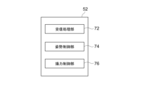
- FIG. 4 shows a functional block diagram of the CPU 52 of the drone 10A.
- the functions of the CPU 52 include a reception processing function, an attitude control function, and a lift control function.
- the CPU 52 functions as a reception processing section 72, an attitude control section 74, and a lift control section 76 by executing a flight processing program 64P.
- FIG. 5 shows a flowchart showing the flight processing program 64P of the drone 10A.
- the flight processing and flight method are executed by the CPU 52 of the drone 10A executing the flight processing program 64P.
- the flight processing program 64P starts when the drone 10A receives an instruction signal transmitted from the remote control device while the rotation of the propellers 18N1, 18N2, 26N10 to 26N40 is stopped. Note that the case where the drone 10A receives an instruction signal transmitted from the remote control device while the rotation of the propellers 18N1, 18N2, and 26N10 to 26N40 is stopped is the case where the drone 10A takes off.
- the instruction signal instructs the content of the flight, specifically, instructs the drone 10A to ascend or descend, and the attitude (for example, forward, backward, tilt, etc.).
- the instruction to raise the drone 10A for example, if there is an instruction to lower, retreat, or tilt the drone 10 while the rotation of the propellers 18N1, 18N2, 26N10 to 26N40 is stopped, flight processing is performed.
- Program 64P starts.
- step 104 the attitude control unit 74 sets the rotational speed of the attitude control propellers 26N10 to 26N40 to a predetermined rotational speed.
- the predetermined rotational speed is a rotational speed at which it is possible to control the attitude of the drone 10A that has risen by rotating the attitude control propellers 26N10 to 26N40.
- step 106 the lift control unit 76 gradually increases the rotational speed of the propellers 18N1 and 18N2 dedicated to lift control, and raises them to a predetermined height. At the time of takeoff, after the attitude of the drone 10A becomes stable, the drone 10A can be raised to a predetermined height.
- step 108 the attitude control unit 74 and the lift control unit 76 cause the drone 10A to fly according to the instruction signal transmitted from the remote control device and received by the receiving device 62 by rotating the propellers 18N1, 18N2, 26N10 to 26N4.
- the motors 16N1, 16N2, and 24N10 to 24N40 are controlled as follows.
- the reception processing unit 72 determines whether the first ascending instruction signal transmitted from the remote control device is received by the receiving device 62.
- the first ascending instruction signal causes the above-mentioned ascending/descending instruction stick of the remote control device to tilt toward the ascending side (first direction) by a predetermined angle or more, causing the drone 10A to move upward and downward at a height H or higher.
- step 112 the lift control section 76 gradually increases the rotational speed of the propeller dedicated to lift control and raises the height h.
- step 114 the reception processing section 72 processes the remote control It is determined whether the first instruction signal transmitted from the first instruction signal is received.
- the first descending instruction signal causes the above-mentioned ascending/descending instruction stick of the remote control device to tilt toward the descending side (second direction) by a predetermined angle or more, causing the drone 10A to move to the ascending/descending instruction stick having a height H or higher.
- step 116 If it is determined that the first descent instruction signal has been received, the flight process proceeds to step 116. If it is not determined that the first descent instruction signal has been received, flight processing proceeds to step 118.
- step 116 the lift control unit 76 gradually reduces the rotational speed of the propeller dedicated to lift control and lowers the propeller by a height h.
- the reception processing unit 72 determines whether the flight is to be stopped by determining whether the instruction signal has not been received for a predetermined period of time. If it is not determined that the flight has stopped, the flight process returns to step 108 and the above processes (steps 108 to 118) are repeated.
- the attitude control unit 74 and the lift control unit 76 execute a flight stop process in step 120.
- the flight stop process is a process for stopping the rotation of the motors 16N1, 16N2, and 24N10 to 24N40.
- the first embodiment can provide a drone 10A having a propeller dedicated to lift control that does not rotate for attitude control of the drone 10A.
- the first embodiment can stabilize the attitude of the drone 10A when raising or lowering the aircraft.
- FIG. 6 shows a top view of a drone 10B according to the second embodiment.
- the drone 10B includes a main body 12B, a plurality of (six in this embodiment) arms 14N21 to 14N23, 22N11 to 22N33, and six arms 14N21 to 14N23 connected to the main body 12B.
- the six propellers 18N21 to 18N23 and 26N11 to 26N33 include three propellers 26N11 to 26N33 for attitude control and three propellers 18N21 to 18N23 dedicated to lift control.
- the propellers 18N21 to 18N23 dedicated to lift control are arranged below arms 14N21 to 14N23 provided with motors 16N21 to 16N23 that rotate the propellers 18N21 to 18N23 dedicated to lift control. This makes it possible to prevent a reduction in lift due to the downwash from propellers 18N21 to 18N23 dedicated to lift control hitting the arms 14N21 to 14N23.
- the length of each blade of the propellers 18N21 to 18N23 dedicated to lift control is longer than the length of each blade of the propellers 26N11 to 26N33 for attitude control. Thereby, more lift can be obtained than when the length of each of the propellers 18N21 to 18N23 dedicated to lift control is shorter than the length of each of propellers 26N11 to 26N33 for attitude control.
- the distance between the center position of each of the attitude control propellers 26N11 to 26N33 and the center of gravity of the drone 10B is longer than the distance between the center position of each of the lift control propellers 18N21 to 18N23 and the center of gravity of the drone 10B.
- the distance between the center position of each of the propellers 26N11 to 26N33 for attitude control and the center of gravity of the drone 10B is shorter than the distance between the center position of each of the propellers 18N21 to 18N23 dedicated for lift control and the center of gravity of the drone 10B.
- the moment of inertia of the propellers 26N11 to 26N33 for attitude control can be increased, and the response of the center of gravity CG attitude control of the drone can be improved.
- FIG. 7 shows a top view of a drone 10C according to the third embodiment.
- the drone 10C includes a main body 12C, a plurality of arms (six in this embodiment) connected to the main body 12C, and six motors provided at the tips of the six arms. 16N31 to 16N34, 30N1, and 30N2, and six propellers 18N31 to 18N34, 26N31, and 26N32 rotated by six motors 16N31 to 16N34, 30N1, and 30N2.
- the six propellers 18N31 to 18N34, 26N31, and 26N32 include two propellers 26N31 and 26N32 for attitude control, and four propellers 18N31 to 18N34 dedicated to lift control.
- the propellers 18N31 to 18N34 dedicated to lift control are arranged below an arm provided with motors 16N21 to 16N23 that rotate the propellers 18N31 to 18N34 dedicated to lift control. This makes it possible to prevent a reduction in lift due to the downwash from the lift control propellers 18N31 to 18N34 hitting the arms.
- the length of each blade of the propellers 18N31 to 18N34 dedicated to lift control is longer than the length of each blade of the propellers 26N31 and 26N32 for attitude control. Thereby, more lift can be obtained than when the length of each of the propellers 18N31 to 18N34 dedicated to lift control is shorter than the length of each of the propellers 26N31 and 26N32 for attitude control.
- the distance between the center position of each of the attitude control propellers 26N31 and 26N32 and the center of gravity of the drone 10C is longer than the distance between the center position of each of the lift control propellers 18N31 to 18N34 and the center of gravity of the drone 10C.
- the distance between each of the propellers 26N31 and 26N32 for attitude control and the center of gravity of the drone 10C is shorter than the distance between each of the propellers 18N31 to 18N34 dedicated for lift control and the center of gravity of the drone 10C.
- the moment of inertia of the propellers 26N11 to 26N33 can be increased, and the response of the center of gravity CG attitude control of the drone 10C can be improved.
- the third embodiment can provide an aircraft having a propeller that does not rotate and ensures lift for controlling the attitude of the aircraft.
- the third embodiment can provide a drone 10C having a propeller dedicated to lift control that does not rotate for attitude control of the drone 10C.
- the relationship between (the number of propellers for attitude control and the number of propellers dedicated to lift control) is (4 and 2) in the first embodiment, and (4 and 2) in the second embodiment. In the embodiment, they are (3 and 3), and in the third embodiment, they are (2 and 4).
- the relationship between (the number of propellers dedicated to lift control and the number of propellers for attitude control) is not limited to these, for example, (2 and 2), (2 and 3), (2 and 5), (2 and 6),... (3 and 2), (3 and 4), (3 and 5), (3 and 6),... (4 and 3), (4 and 4), (4 and 5), (4 and 6),... (5 and 2),... (6 and 2),... ... But that's fine.
- each component may exist as long as there is no contradiction.
- flight processing is realized by a software configuration using a computer, but the technology of the present disclosure is not limited to this.
- a software configuration using a computer instead of a software configuration using a computer, only the hardware configuration such as FPGA (FIELD -PROGRAMMABLE GATE ARRAY) or ASIC (Application Specific INTEGRATED CIRCUIT).
- Flight processing may be executed. Part of the flight processing may be executed by a software configuration, and the remaining processes may be executed by a hardware configuration.
- Non-transitory computer-readable media includes various types of tangible storage media.
- Examples of non-transitory computer-readable media include magnetic recording media (e.g., flexible disks, magnetic tapes, hard disk drives), magneto-optical recording media (e.g., magneto-optical disks), CD-ROMs (Read Only Memory), CD-Rs, and CDs. - R/W, semiconductor memory (for example, mask ROM, PROM (Programmable ROM), EPROM (Erasable PROM), flash ROM, RAM (Random Access Memory)).
- the program may also be provided to the computer on various types of temporary computer-readable media. Examples of transitory computer-readable media include electrical signals, optical signals, and electromagnetic waves.
- the temporary computer-readable medium can provide the program to the computer via wired communication channels, such as electrical wires and fiber optics, or wireless communication channels.
Landscapes
- Engineering & Computer Science (AREA)
- Aviation & Aerospace Engineering (AREA)
- Mechanical Engineering (AREA)
- Control Of Position, Course, Altitude, Or Attitude Of Moving Bodies (AREA)
Priority Applications (2)
| Application Number | Priority Date | Filing Date | Title |
|---|---|---|---|
| JP2024511024A JPWO2023188266A1 (https=) | 2022-03-31 | 2022-03-31 | |
| PCT/JP2022/016515 WO2023188266A1 (ja) | 2022-03-31 | 2022-03-31 | 航空機 |
Applications Claiming Priority (1)
| Application Number | Priority Date | Filing Date | Title |
|---|---|---|---|
| PCT/JP2022/016515 WO2023188266A1 (ja) | 2022-03-31 | 2022-03-31 | 航空機 |
Publications (1)
| Publication Number | Publication Date |
|---|---|
| WO2023188266A1 true WO2023188266A1 (ja) | 2023-10-05 |
Family
ID=88199863
Family Applications (1)
| Application Number | Title | Priority Date | Filing Date |
|---|---|---|---|
| PCT/JP2022/016515 Ceased WO2023188266A1 (ja) | 2022-03-31 | 2022-03-31 | 航空機 |
Country Status (2)
| Country | Link |
|---|---|
| JP (1) | JPWO2023188266A1 (https=) |
| WO (1) | WO2023188266A1 (https=) |
Citations (4)
| Publication number | Priority date | Publication date | Assignee | Title |
|---|---|---|---|---|
| US20160325829A1 (en) * | 2015-05-08 | 2016-11-10 | Gwangju Institute Of Science And Technology | Multirotor type unmanned aerial vehicle available for adjusting direction of thrust |
| JP2017193321A (ja) * | 2016-04-19 | 2017-10-26 | 株式会社石川エナジーリサーチ | エンジン搭載型マルチコプター |
| US10011353B1 (en) * | 2015-02-02 | 2018-07-03 | Amazon Technologies, Inc. | Maneuvering an unmanned aerial vehicle without considering the effects of gravity |
| JP6979251B1 (ja) * | 2021-10-07 | 2021-12-08 | 株式会社石川エナジーリサーチ | 飛行装置 |
Family Cites Families (1)
| Publication number | Priority date | Publication date | Assignee | Title |
|---|---|---|---|---|
| AU6761996A (en) * | 1995-07-20 | 1997-02-18 | Dallas Semiconductor Corporation | Method and apparatus for encryption key creation |
-
2022
- 2022-03-31 WO PCT/JP2022/016515 patent/WO2023188266A1/ja not_active Ceased
- 2022-03-31 JP JP2024511024A patent/JPWO2023188266A1/ja active Pending
Patent Citations (4)
| Publication number | Priority date | Publication date | Assignee | Title |
|---|---|---|---|---|
| US10011353B1 (en) * | 2015-02-02 | 2018-07-03 | Amazon Technologies, Inc. | Maneuvering an unmanned aerial vehicle without considering the effects of gravity |
| US20160325829A1 (en) * | 2015-05-08 | 2016-11-10 | Gwangju Institute Of Science And Technology | Multirotor type unmanned aerial vehicle available for adjusting direction of thrust |
| JP2017193321A (ja) * | 2016-04-19 | 2017-10-26 | 株式会社石川エナジーリサーチ | エンジン搭載型マルチコプター |
| JP6979251B1 (ja) * | 2021-10-07 | 2021-12-08 | 株式会社石川エナジーリサーチ | 飛行装置 |
Also Published As
| Publication number | Publication date |
|---|---|
| JPWO2023188266A1 (https=) | 2023-10-05 |
Similar Documents
| Publication | Publication Date | Title |
|---|---|---|
| JP7603699B2 (ja) | ティルティングファンアッセンブリを備えた航空機 | |
| US10077107B1 (en) | Bimodal propeller aircraft | |
| CN108639332B (zh) | 复合三旋翼无人机多模态飞行控制方法 | |
| CN105620741B (zh) | 一种飞行器控制方法及其控制的飞行器 | |
| KR101767943B1 (ko) | 추력의 방향 설정이 가능한 멀티로터 타입의 무인 비행체 | |
| US20210120176A1 (en) | Method of controlling gimbal, gimbal and uav | |
| CA3089627A1 (en) | Methods and systems for energy-efficient take-offs and landings for vertical take-off and landing (vtol) aerial vehicles | |
| WO2021057601A1 (zh) | 一种无人机飞行方法、装置和无人机 | |
| CN111605708A (zh) | 偏转翼飞行器 | |
| KR20170135577A (ko) | 틸팅 및 가변 피치 시스템이 적용된 무인 비행체 | |
| WO2021023187A1 (zh) | 一种倾转旋翼无人机的控制方法及倾转旋翼无人机 | |
| CN108845581A (zh) | 复合四旋翼无人机多模态飞行控制方法 | |
| CN108572655B (zh) | 飞行控制方法及相关装置 | |
| JP2021003915A (ja) | マルチコプター | |
| WO2023188266A1 (ja) | 航空機 | |
| CN207902745U (zh) | 一种无人飞行器 | |
| EP4353590A1 (en) | Tilt-wing aircraft, a control system for the aircraft and a method of controlling the aircraft | |
| CN217864731U (zh) | 一种旋翼结构及飞行器 | |
| CN111766888A (zh) | 基于飞行器的控制方法以及飞行器 | |
| JP7572701B2 (ja) | マルチローター航空機 | |
| CN115817808A (zh) | 飞行控制方法、装置及飞行器 | |
| WO2023188269A1 (ja) | 回転翼機 | |
| CN221738107U (zh) | 一种固定翼飞行器 | |
| KR20190009626A (ko) | 안전한 수직 착륙을 위한 틸팅 가능한 수단을 사용하는 비행체 | |
| CN108190012B (zh) | 飞行器及其控制方法 |
Legal Events
| Date | Code | Title | Description |
|---|---|---|---|
| 121 | Ep: the epo has been informed by wipo that ep was designated in this application |
Ref document number: 22935411 Country of ref document: EP Kind code of ref document: A1 |
|
| ENP | Entry into the national phase |
Ref document number: 2024511024 Country of ref document: JP Kind code of ref document: A |
|
| NENP | Non-entry into the national phase |
Ref country code: DE |
|
| 122 | Ep: pct application non-entry in european phase |
Ref document number: 22935411 Country of ref document: EP Kind code of ref document: A1 |