WO2023188082A1 - 加工装置 - Google Patents
加工装置 Download PDFInfo
- Publication number
- WO2023188082A1 WO2023188082A1 PCT/JP2022/015889 JP2022015889W WO2023188082A1 WO 2023188082 A1 WO2023188082 A1 WO 2023188082A1 JP 2022015889 W JP2022015889 W JP 2022015889W WO 2023188082 A1 WO2023188082 A1 WO 2023188082A1
- Authority
- WO
- WIPO (PCT)
- Prior art keywords
- processing
- processing light
- light
- irradiation
- optical system
- Prior art date
- Legal status (The legal status is an assumption and is not a legal conclusion. Google has not performed a legal analysis and makes no representation as to the accuracy of the status listed.)
- Ceased
Links
Images











Classifications
-
- B—PERFORMING OPERATIONS; TRANSPORTING
- B23—MACHINE TOOLS; METAL-WORKING NOT OTHERWISE PROVIDED FOR
- B23K—SOLDERING OR UNSOLDERING; WELDING; CLADDING OR PLATING BY SOLDERING OR WELDING; CUTTING BY APPLYING HEAT LOCALLY, e.g. FLAME CUTTING; WORKING BY LASER BEAM
- B23K26/00—Working by laser beam, e.g. welding, cutting or boring
- B23K26/34—Laser welding for purposes other than joining
- B23K26/342—Build-up welding
-
- B—PERFORMING OPERATIONS; TRANSPORTING
- B23—MACHINE TOOLS; METAL-WORKING NOT OTHERWISE PROVIDED FOR
- B23K—SOLDERING OR UNSOLDERING; WELDING; CLADDING OR PLATING BY SOLDERING OR WELDING; CUTTING BY APPLYING HEAT LOCALLY, e.g. FLAME CUTTING; WORKING BY LASER BEAM
- B23K15/00—Electron-beam welding or cutting
- B23K15/004—Tandem beams or torches, i.e. working simultaneously with several beams or torches
-
- B—PERFORMING OPERATIONS; TRANSPORTING
- B23—MACHINE TOOLS; METAL-WORKING NOT OTHERWISE PROVIDED FOR
- B23K—SOLDERING OR UNSOLDERING; WELDING; CLADDING OR PLATING BY SOLDERING OR WELDING; CUTTING BY APPLYING HEAT LOCALLY, e.g. FLAME CUTTING; WORKING BY LASER BEAM
- B23K15/00—Electron-beam welding or cutting
- B23K15/0046—Welding
- B23K15/0086—Welding welding for purposes other than joining, e.g. build-up welding
-
- B—PERFORMING OPERATIONS; TRANSPORTING
- B23—MACHINE TOOLS; METAL-WORKING NOT OTHERWISE PROVIDED FOR
- B23K—SOLDERING OR UNSOLDERING; WELDING; CLADDING OR PLATING BY SOLDERING OR WELDING; CUTTING BY APPLYING HEAT LOCALLY, e.g. FLAME CUTTING; WORKING BY LASER BEAM
- B23K26/00—Working by laser beam, e.g. welding, cutting or boring
- B23K26/02—Positioning or observing the workpiece, e.g. with respect to the point of impact; Aligning, aiming or focusing the laser beam
- B23K26/06—Shaping the laser beam, e.g. by masks or multi-focusing
- B23K26/0604—Shaping the laser beam, e.g. by masks or multi-focusing by a combination of beams
-
- B—PERFORMING OPERATIONS; TRANSPORTING
- B23—MACHINE TOOLS; METAL-WORKING NOT OTHERWISE PROVIDED FOR
- B23K—SOLDERING OR UNSOLDERING; WELDING; CLADDING OR PLATING BY SOLDERING OR WELDING; CUTTING BY APPLYING HEAT LOCALLY, e.g. FLAME CUTTING; WORKING BY LASER BEAM
- B23K26/00—Working by laser beam, e.g. welding, cutting or boring
- B23K26/08—Devices involving relative movement between laser beam and workpiece
- B23K26/082—Scanning systems, i.e. devices involving movement of the laser beam relative to the laser head
-
- B—PERFORMING OPERATIONS; TRANSPORTING
- B23—MACHINE TOOLS; METAL-WORKING NOT OTHERWISE PROVIDED FOR
- B23K—SOLDERING OR UNSOLDERING; WELDING; CLADDING OR PLATING BY SOLDERING OR WELDING; CUTTING BY APPLYING HEAT LOCALLY, e.g. FLAME CUTTING; WORKING BY LASER BEAM
- B23K26/00—Working by laser beam, e.g. welding, cutting or boring
- B23K26/14—Working by laser beam, e.g. welding, cutting or boring using a fluid stream, e.g. a jet of gas, in conjunction with the laser beam; Nozzles therefor
- B23K26/144—Working by laser beam, e.g. welding, cutting or boring using a fluid stream, e.g. a jet of gas, in conjunction with the laser beam; Nozzles therefor the fluid stream containing particles, e.g. powder
-
- B—PERFORMING OPERATIONS; TRANSPORTING
- B23—MACHINE TOOLS; METAL-WORKING NOT OTHERWISE PROVIDED FOR
- B23K—SOLDERING OR UNSOLDERING; WELDING; CLADDING OR PLATING BY SOLDERING OR WELDING; CUTTING BY APPLYING HEAT LOCALLY, e.g. FLAME CUTTING; WORKING BY LASER BEAM
- B23K26/00—Working by laser beam, e.g. welding, cutting or boring
- B23K26/14—Working by laser beam, e.g. welding, cutting or boring using a fluid stream, e.g. a jet of gas, in conjunction with the laser beam; Nozzles therefor
- B23K26/1462—Nozzles; Features related to nozzles
- B23K26/1464—Supply to, or discharge from, nozzles of media, e.g. gas, powder, wire
- B23K26/147—Features outside the nozzle for feeding the fluid stream towards the workpiece
Definitions
- the present invention relates, for example, to the technical field of a processing device that can perform additional processing on an object.
- Patent Document 1 An example of a processing device that can perform additional processing on an object is described in Patent Document 1.
- One of the technical challenges for such processing devices is properly processing objects.
- the first processing light emitted from the first light source and the second processing light emitted from the second light source different from the first light source and having a different peak wavelength from the first processing light.
- an irradiation optical system capable of irradiating an object, and a material supply member capable of supplying a modeling material to a molten pool formed by the first and second processing lights, the peak wavelength of the second processing light being is shorter than the peak wavelength of the first processing light, and a second region irradiated with the second processing light is wider than a first region irradiated with the first processing light.
- the processing device performs additional processing on an object, the first optical system capable of irradiating the object with a first processing light emitted from a first light source, and the first light source.
- a second optical system capable of irradiating the object with second processing light emitted from a different second light source and having a peak wavelength different from that of the first processing light; and a molten pool formed by the first and second processing light.
- a material supply member capable of supplying a modeling material
- the first optical system includes a first condenser that can change the condensing position of the first processing light along the irradiation direction of the first processing light.
- a light position changing member capable of deflecting the first processing light so as to change a first irradiation position where the first processing light is irradiated along a direction intersecting the irradiation direction of the first processing light
- a first deflection member the second optical system includes a second focusing position changing member capable of changing the focusing position of the second processing light along the irradiation direction of the second processing light; a second deflection member capable of deflecting the second processing light so as to change a second irradiation position where the second processing light is irradiated along a direction intersecting the irradiation direction of the second processing light; Processing equipment is provided.
- a processing apparatus that performs additional processing on an object, wherein the object is irradiated with first processing light emitted from a first light source, and a second light source different from the first light source.
- a first optical system capable of irradiating the object with second processing light emitted from the object and having a peak wavelength different from that of the first processing light; and a molten pool formed by the first and second processing lights, a modeling material.
- a material supplying member capable of supplying the first processing light
- the first optical system includes a first focusing position changing member capable of changing the focusing position of the first processing light along the irradiation direction of the first processing light.
- a processing device including a first deflection member capable of deflecting processing light is provided.
- the processing apparatus performs additional processing on an object, and is capable of irradiating the object with a first processing light, and irradiates the object with a second processing light having a different peak wavelength from the first processing light.
- a first optical system capable of irradiating an object; and a second optical system capable of irradiating the object with a fourth processing light having a peak wavelength different from that of the third processing light.
- the first optical system includes a first light focusing position changing member capable of changing the focusing position of the first processing light along the irradiation direction of the first processing light; a second light focusing position changing member that can be changed along the irradiation direction of the processing light; a first irradiation position where the first processing light is irradiated; and a second irradiation position where the second processing light is irradiated; a first deflection member capable of deflecting the first processing light and the second processing light so as to change the direction intersecting the irradiation direction of the first processing light and the second processing light;
- the second optical system includes a third light focusing position changing member capable of changing the focusing position of the third processing light along the irradiation direction of the third processing light, and a focusing position of the fourth processing light, 3.
- a fourth condensing position changing member that can be changed along the irradiation direction of the fourth processing light, a third irradiation position where the third processing light is irradiated, and a fourth irradiation where the fourth processing light is irradiated.
- a second deflection member capable of deflecting the third processing light and the fourth processing light so as to change the position along a direction intersecting the irradiation direction of the third processing light and the fourth processing light;
- a processing apparatus is provided that includes.
- a processing apparatus that performs additional processing on an object, the first optical system capable of irradiating the object with a first processing light, and the second optical system capable of irradiating the object with a second processing light.
- the first optical system includes an optical system and a material supply member capable of supplying a modeling material to a molten pool formed by the first and second processing lights, and the first optical system is configured to control the condensing position of the first processing lights. , a first light focusing position changing member that can be changed along the irradiation direction of the first processing light, and a first irradiation position where the first processing light is irradiated, intersecting the irradiation direction of the first processing light.
- a first deflection member capable of deflecting the first processing light so as to change along a first direction
- the second optical system changes the condensing position of the second processing light to
- a second light focusing position changing member that can be changed along the light irradiation direction and a second irradiation position where the second processing light is irradiated are arranged along a second direction intersecting the irradiation direction of the second processing light.
- a second deflection member capable of deflecting the second processing light so as to change the processing light.
- a processing apparatus that performs additional processing on an object, the first optical system capable of irradiating the object with a first processing light, and the second optical system capable of irradiating the object with a second processing light.
- an optical system capable of supplying a modeling material to a molten pool formed by the first and second processing lights; a first deflection member capable of deflecting the first processing light so as to change the irradiation position along a direction intersecting the irradiation direction of the first processing light; and a first deflection member capable of deflecting the first processing light, and detecting the intensity of the first processing light.
- a processing apparatus including a second deflection member capable of deflecting the second processing light, and a second detector capable of detecting the intensity of the second processing light.
- the processing head includes a focusing optical system that focuses processing light on an object, an electrical component used to control the processing light, and an optical axis of the focusing optical system.
- a support member adjacent to the processing head and supporting the processing head along the intersecting direction, the first distance between the electrical component and the support member in the direction intersecting the optical axis,
- a processing device is provided that is longer than a second distance between the optical axis and the support member in a direction intersecting the optical axis.
- an irradiation device capable of irradiating an object with a first processing light and a second processing light having a peak wavelength different from that of the first processing light;
- a processing device includes a material supply member capable of supplying a modeling material to a molten pool formed by at least one of the parts.
- an irradiation device capable of irradiating an object with a first processing light and a second processing light having a peak wavelength different from that of the first processing light; 2.
- a processing device includes a material supply member capable of supplying a modeling material at a position where the processing light is irradiated.
- an irradiation device capable of irradiating an object with a first processing light and a second processing light having a peak wavelength different from that of the first processing light;
- the irradiation area to be irradiated is provided with a material supply member capable of supplying a modeling material, and the irradiation area to which the first processing light is irradiated is at least partially overlapped with the area to which the second processing light is irradiated.
- Equipment is provided.
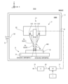
- FIG. 1 is a sectional view showing the appearance of the processing system of this embodiment.
- FIG. 2 is a sectional view showing the structure of the processing system of this embodiment.
- FIG. 3 is a block diagram showing the configuration of the processing system of this embodiment.
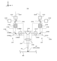
- FIG. 4 is a cross-sectional view showing the structure of the irradiation optical system.
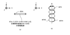
- FIG. 5(a) is a plan view showing the movement trajectory of the target irradiation area within the processing unit area
- FIG. 5(b) is a plan view showing the movement trajectory of the target irradiation area on the modeling surface.
- FIGS. 6(a) and 6(b) is a plan view showing the movement locus of the target irradiation area within the processing unit area
- FIG. 6(c) is a plan view showing the movement locus of the target irradiation area on the modeling surface.
- FIG. 3 is a plan view showing a movement trajectory.
- FIG. 7 is a perspective view showing a housing unit in which the irradiation optical system is housed.
- FIG. 8 is a bottom view showing the positional relationship between the X scanning motor and the Y scanning motor.
- FIG. 9 is a cross-sectional view showing an example of an irradiation optical system housed in a head housing to facilitate maintenance of the irradiation optical system.
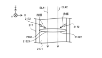
- FIG. 10 is a cross-sectional view showing a coolant supply nozzle that supplies coolant to at least a portion of the irradiation optical system.
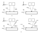
- FIGS. 11(a) to 11(e) is a cross-sectional view showing a situation in which a certain area on a workpiece is irradiated with processing light and a modeling material is supplied.
- FIGS. 11(a) to 11(e) is a cross-sectional view showing a situation in which a certain area on a workpiece is irradiated with processing light and a modeling material is supplied.
- FIGS. 11(a) to 11(e) is a cross-sectional view showing a situation in which a certain area on
- FIG. 12(a) to 12(c) is a cross-sectional view showing the process of modeling a three-dimensional structure.
- FIGS. 13(a) to 13(c) is a cross-sectional view showing two processing lights irradiated onto the modeling surface.
- FIGS. 14(a) and 14(b) is a cross-sectional view showing a three-dimensional structure modeled using a plurality of different types of modeling materials M.
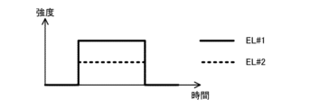
- FIG. 15 is a timing chart showing the intensities of the two processing lights.
- FIG. 16 is a timing chart showing the intensities of the two processing lights.
- FIG. 17 is a timing chart showing the intensities of the two processing lights.
- FIG. 18 is a timing chart showing the intensities of the two processing lights.
- FIG. 15 is a timing chart showing the intensities of the two processing lights.
- FIG. 16 is a timing chart showing the intensities of the two processing lights.
- FIG. 17 is a timing chart showing the intensities of the two processing lights.
- FIG. 19(a) is a plan view showing two beam spots formed on the modeling surface by two processing lights
- FIG. 19(b) is a plan view showing two beam spots (that is, two target irradiation areas). It is a top view which shows the movement locus on a modeling surface.
- FIG. 20(a) is a plan view showing two beam spots formed by two processing lights on the modeling surface
- FIG. 20(b) is a plan view showing two beam spots (that is, two target irradiation areas). It is a top view which shows the movement locus on a modeling surface.
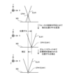
- FIG. 21 is a cross-sectional view showing processing light when a galvano-focus interlock control operation is performed to control the galvano mirror based on the control amount of the focus control optical system.
- FIG. 21 is a cross-sectional view showing processing light when a galvano-focus interlock control operation is performed to control the galvano mirror based on the control amount of the focus control optical system.
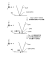
- FIG. 22 is a cross-sectional view showing processing light when a galvano-focus interlock control operation is performed to control the focus control optical system based on the control amount of the galvano mirror.
- FIG. 23 is a cross-sectional view showing the structure of the irradiation optical system included in the processing system in the first modification.
- FIG. 24 is a cross-sectional view showing the structure of the irradiation optical system included in the processing system in the second modification.
- FIG. 25 is a block diagram showing the configuration of a processing system in the third modification.
- FIG. 26 is a cross-sectional view showing the structure of the irradiation optical system included in the processing system in the third modification.
- FIG. 27 is a cross-sectional view showing the structure of the irradiation optical system included in the processing system in the fourth modification.
- FIG. 28 is a cross-sectional view showing the structure of the irradiation optical system included in the processing system in the fifth modification.
- FIG. 29 is a cross-sectional view showing the structure of the irradiation optical system included in the processing system in the fifth modification.
- FIG. 30 is a cross-sectional view showing the structure of the irradiation optical system included in the processing system in the sixth modification.
- a processing apparatus and a processing method will be described using a processing system SYS that can process a workpiece W, which is an example of an object.
- a processing system SYS that performs additional processing based on laser metal deposition (LMD).
- Additional processing based on the laser metallization welding method melts the modeling material M supplied to the workpiece W with processing light EL (that is, an energy beam having the form of light), thereby forming a part that is integrated with the workpiece W or a part of the workpiece W.
- processing light EL that is, an energy beam having the form of light
- each of the X-axis direction and the Y-axis direction is a horizontal direction (that is, a predetermined direction within a horizontal plane), and the Z-axis direction is a vertical direction (that is, a direction perpendicular to the horizontal plane). (and substantially in the vertical direction).
- the rotation directions (in other words, the tilt directions) around the X-axis, Y-axis, and Z-axis are referred to as the ⁇ X direction, the ⁇ Y direction, and the ⁇ Z direction, respectively.
- the Z-axis direction may be the direction of gravity.
- the XY plane may be set in the horizontal direction.
- FIG. 1 is a perspective view schematically showing the appearance of the processing system SYS of this embodiment.
- FIG. 2 is a sectional view schematically showing the structure of the processing system SYS of this embodiment.
- FIG. 3 is a system configuration diagram showing the system configuration of the processing system SYS of this embodiment.
- the processing system SYS is capable of performing additional processing on the workpiece W.
- the processing system SYS can form a molded object that is integrated with (or is separable from) the workpiece W by performing additional processing on the workpiece W.
- the additional processing performed on the workpiece W corresponds to processing for adding a shaped object to the workpiece W that is integrated with (or separable from) the workpiece W.
- the modeled object in this embodiment may mean any object modeled by the processing system SYS.
- the processing system SYS uses a three-dimensional structure (that is, a three-dimensional structure that has a size in any three-dimensional direction) as an example of a modeled object. , a structure having dimensions in the Y-axis direction and the Z-axis direction) ST can be formed.
- the processing system SYS can perform additional processing on the stage 31.
- the workpiece W is a placed object, which is an object placed on the stage 31, the processing system SYS can perform additional processing on the placed object.
- the object placed on the stage 31 may be another three-dimensional structure ST (that is, an existing structure) modeled by the processing system SYS.
- FIGS. 1 and 2 show an example in which the workpiece W is an existing structure placed on a stage 31. Further, the explanation will be continued below using an example in which the workpiece W is an existing structure placed on the stage 31.
- the workpiece W may be an item that requires repair and has a defective part.
- the processing system SYS may perform repair processing to repair the item requiring repair by performing additional processing to form a modeled object to compensate for the missing portion. That is, the additional processing performed by the processing system SYS may include additional processing that adds a shaped object to the workpiece W to compensate for a missing portion.
- the processing system SYS is capable of performing additional processing based on the laser overlay welding method.
- the processing system SYS can be said to be a 3D printer that processes objects using layered processing technology.
- the layered processing technology may also be referred to as rapid prototyping, rapid manufacturing, or additive manufacturing.
- the laser deposition welding method may be referred to as DED (Directed Energy Deposition).
- the processing system SYS using the lamination processing technique forms a three-dimensional structure ST in which the plurality of structural layers SL are stacked by sequentially forming a plurality of structural layers SL (see FIG. 12 described later).
- the processing system SYS first sets the surface of the workpiece W as a modeling surface MS for actually modeling the object, and models the first structural layer SL on the modeling surface MS.
- the processing system SYS sets the surface of the first structural layer SL as a new modeling surface MS, and models the second structural layer SL on the new modeling surface MS.
- the processing system SYS repeats the same operation to form a three-dimensional structure ST in which a plurality of structural layers SL are stacked.
- the processing system SYS performs additional processing by processing the modeling material M using the processing light EL, which is an energy beam.
- the modeling material M is a material that can be melted by irradiation with processing light EL having a predetermined intensity or higher.
- a modeling material M for example, at least one of a metallic material and a resinous material can be used.
- the metallic material include at least one of a material containing copper, a material containing tungsten, and a material containing stainless steel.
- the modeling material M other materials different from metal materials and resin materials may be used.
- the modeling material M is a powder material. That is, the modeling material M is a powder. However, the modeling material M may not be a powder.
- at least one of a wire-shaped modeling material and a gaseous modeling material may be used.
- the workpiece W may also be an object containing a material that can be melted by irradiation with the processing light EL having a predetermined intensity or higher.
- the material of the work W may be the same as the modeling material M, or may be different.
- the material of the workpiece W for example, at least one of a metallic material and a resinous material can be used.
- the metallic material include at least one of a material containing copper, a material containing tungsten, and a material containing stainless steel.
- other materials different from the metallic material and the resinous material may be used.
- the processing system SYS includes a material supply source 1, a processing unit 2, a stage unit 3, a light source 4, a gas supply source 5, and a control device, as shown in FIGS. 1 to 3. 7.
- the processing unit 2 and the stage unit 3 may be housed in a chamber space 63IN inside the housing 6.
- the processing system SYS may perform additional processing in the chamber space 63IN.
- at least one of the processing system SYS and the processing unit 2 may be referred to as a processing device.
- a material supply source 1 supplies a modeling material M to a processing unit 2.
- the material supply source 1 supplies a desired amount of modeling material M according to the required amount so that the amount of modeling material M required per unit time to perform additional processing is supplied to the processing unit 2. do.
- the processing unit 2 processes the modeling material M supplied from the material supply source 1 to create a modeled object.
- the processing unit 2 includes a processing head 21 and a head drive system 22.
- the processing head 21 includes an irradiation optical system 211 and a plurality of material nozzles 212.
- the processing head 21 may include a plurality of irradiation optical systems 211.
- Processing head 21 may include a single material nozzle 212.
- the irradiation optical system 211 is an optical system for emitting processing light EL. Specifically, the irradiation optical system 211 is optically connected to the light source 4 that emits (generates) the processing light EL via the light transmission member 41.
- An example of the optical transmission member 41 is at least one of an optical fiber and a light pipe.
- the processing system SYS includes two light sources 4 (specifically, light sources 4#1 and 4#2), and the irradiation optical system 211 includes a light transmission member 41#1. and 41#2, they are optically connected to light sources 4#1 and 4#2, respectively.
- the irradiation optical system 211 receives processing light EL propagating from the light source 4#1 via the light transmission member 41#1 and processing light EL propagating from the light source 4#2 via the light transmission member 41#2. and eject both.
- processing light EL when it is necessary to distinguish between the two processing lights EL emitted by the irradiation optical system 211, the processing light EL generated by the light source 4#1 may be referred to as “processing light EL” as necessary. #1”, and the processing light EL generated by the light source 4#2 is called “processing light EL#2”.
- the irradiation optical system 211 emits the processing light EL downward (that is, to the ⁇ Z side).
- a stage 31 is arranged below the irradiation optical system 211.
- the irradiation optical system 211 irradiates the molding surface MS with the emitted processing light EL.
- the irradiation optical system 211 may be referred to as an irradiation device.
- the irradiation optical system 211 directs the processing light to a target irradiation area (target irradiation position) EA that is set on the modeling surface MS as an area where the processing light EL is irradiated (typically, focused).
- the irradiation optical system 211 may change the processing light EL as necessary.
- the target irradiation area EA to which the processing light EL#1 is irradiated is referred to as the "target irradiation area EA#1"
- the target irradiation area EA to which the irradiation optical system 211 irradiates the processing light EL#2 is referred to as the "target irradiation area EA#2”. ”.
- the state of the irradiation optical system 211 can be switched between a state in which the target irradiation area EA is irradiated with the processed light EL and a state in which the target irradiation area EA is not irradiated with the processed light EL under the control of the control device 7.
- the direction of the processing light EL emitted from the irradiation optical system 211 is not limited to directly below (that is, coincident with the ⁇ Z-axis direction), but may be, for example, a direction tilted by a predetermined angle with respect to the Z-axis. Good too.
- the third optical system 216 (or the f ⁇ lens 2162 described below), which will be described later, is not limited to an optical system that is telecentric on the object side, but may be an optical system that is non-telecentric on the object side.
- the irradiation optical system 211 may form a molten pool MP on the modeling surface MS by irradiating the processing light EL to the modeling surface MS.
- the irradiation optical system 211 may form the molten pool MP#1 on the modeling surface MS by irradiating the processing light EL#1 onto the modeling surface MS.
- the irradiation optical system 211 may form the molten pool MP#2 on the modeling surface MS by irradiating the processing light EL#2 onto the modeling surface MS.
- Molten pool MP#1 and molten pool MP#2 may be integrated. Alternatively, molten pool MP#1 and molten pool MP#2 may be separated from each other.
- the molten pool MP#1 may not be formed on the modeling surface MS by the irradiation with the processing light EL#1.
- the molten pool MP#2 may not be formed on the modeling surface MS by the irradiation with the processing light EL#2.
- the material nozzle 212 supplies (for example, injects, jets, squirts, or sprays) the modeling material M.
- material nozzle 212 may be referred to as a material supply member.
- the material nozzle 212 is physically connected to the material supply source 1, which is a supply source of the modeling material M, via the supply pipe 11 and the mixing device 12.
- the material nozzle 212 supplies the modeling material M supplied from the material supply source 1 via the supply pipe 11 and the mixing device 12 .
- the material nozzle 212 may force-feed the modeling material M supplied from the material supply source 1 via the supply pipe 11.
- the modeling material M from the material supply source 1 and the transport gas (that is, a pressurized gas, for example, an inert gas such as nitrogen or argon) are mixed in the mixing device 12 and then passed through the supply pipe 11.
- the material may be pumped through the material nozzle 212 .
- the material nozzle 212 supplies the modeling material M together with the transport gas.
- the transport gas for example, purge gas supplied from the gas supply source 5 is used.
- a gas supplied from a gas supply source different from the gas supply source 5 may be used.
- the material nozzle 212 is drawn in a tube shape in FIG. 2, the shape of the material nozzle 212 is not limited to this shape.
- the material nozzle 212 supplies the modeling material M downward (that is, to the -Z side).
- a stage 31 is arranged below the material nozzle 212.
- the material nozzle 212 supplies the modeling material M toward the modeling surface MS. Note that the direction in which the modeling material M supplied from the material nozzle 212 is inclined at a predetermined angle (for example, an acute angle) with respect to the Z-axis direction, but even if it is on the ⁇ Z side (that is, directly below) good.
- the material nozzle 212 applies the modeling material M to a position where at least one of the processing lights EL#1 and EL#2 is irradiated (that is, at least one of the target irradiation areas EA#1 and EA#2). supply Therefore, the target supply area MA, which is set on the modeling surface MS as the area where the material nozzle 212 supplies the modeling material M, is configured to at least partially overlap with at least one of the target irradiation areas EA#1 and EA#2. , the material nozzle 212 and the irradiation optical systems 211#1 and 211#2 are aligned.
- the size of the target supply area MA may be larger than, smaller than, or the same as the size of at least one of the target irradiation areas EA#1 and EA#2.
- the material nozzle 212 may supply the modeling material M to the molten pool MP. Specifically, the material nozzle 212 may supply the modeling material M to at least one of the molten pool MP#1 and the molten pool MP#2. As described above, since the material nozzle 212 supplies the modeling material M from above the workpiece W, the material nozzle 212 supplies the modeling material M from a position away from the molten pool MP formed on the workpiece W. It may be assumed that there is. However, the material nozzle 212 does not need to supply the modeling material M to the molten pool MP.
- the processing system SYS melts the modeling material M from the material nozzle 212 with the processing light EL emitted from the irradiation optical system 211 before the modeling material M reaches the workpiece W, and transfers the melted modeling material M to the workpiece W. It may be attached to W.
- the processing head 21 may be housed in the head housing 23.
- the head housing 23 is a housing in which a housing space 231 (see FIG. 7 described later) for housing the irradiation optical system 211 and the material nozzle 212 is formed.
- the irradiation optical system 211 and the material nozzle 212 may be housed in the head housing 23.
- the head housing 23 may function as a support member that supports the processing head 21.
- the head housing 23 may be adjacent to the processing head 21 along a direction intersecting the Z-axis direction (for example, a direction along the XY plane).
- the head housing 23 may include a member adjacent to the processing head 21 along a direction intersecting the Z-axis direction (for example, a direction along the XY plane). Note that the head housing 23 will be described in detail later with reference to FIG. 7, etc., which will be described later.
- the head drive system 22 moves the processing head 21 under the control of the control device 7. That is, the head drive system 22 moves the irradiation optical system 211 and the material nozzle 212 under the control of the control device 7 .
- the head drive system 22 moves the processing head 21 along at least one of the X-axis direction, the Y-axis direction, the Z-axis direction, the ⁇ X direction, the ⁇ Y direction, and the ⁇ Z direction, for example.
- the operation of moving the processing head 21 along at least one of the ⁇ X direction, ⁇ Y direction, and ⁇ Z direction includes the rotational axis along the X-axis, the Y-axis, and the Z-axis. It may be considered that the operation is equivalent to rotating the processing head 21 around at least one rotation.
- the head drive system 22 moves the processing head 21 along the X-axis direction and the Z-axis direction.
- the head drive system 22 is attached to (or formed on) a column 221, which is a wall-shaped member extending upward along the Z-axis direction from the bed 30, which is the base of the stage unit 3, and the column 221, for example.
- a column 221 which is a wall-shaped member extending upward along the Z-axis direction from the bed 30, which is the base of the stage unit 3, and the column 221, for example.
- an X guide member 222 extending along the X-axis direction
- an X block member 223 attached to the X guide member 222 and movable along the X guide member 222
- a servo motor 224 that generates a force, a Z guide member 225 that is attached to (or formed on) the X block member 223 and extends along the Z-axis direction, and a Z guide member 225 that is attached to the Z guide member 225 and extends along the Z guide member 225.
- the Z-block member 226 may be movable, and a servo motor 227 that generates a driving force for moving the Z-block member 226 may be provided.
- the head drive system 22 particularly the Z block member 226) to which the processing head 21 is attached may be considered to be a support member that supports the processing head 21.
- the processing head 21 may be attached to the Z block member 226.
- the head housing 23 that accommodates the processing head 21 may be attached to the Z block member 226.
- the Z block member 226 may function as a support member that supports the processing head 21.
- the Z block member 226 may be adjacent to the processing head 21 along a direction intersecting the Z-axis direction (for example, a direction along the XY plane).
- the processing head 21 moves in the X-axis direction as the X-block member 223 moves, and moves in the Z-axis direction as the Z-block member 226 moves.
- the position of the processing head 21 in the X-axis direction changes, and as the position of the Z-block member 226 changes in the Z-axis direction, the position of the processing head 21 in the Z-axis direction changes.
- the position of the processing head 21 in is changed.
- the relative positional relationship between the processing head 21 and the stage 31 and the work W placed on the stage 31 changes.
- the positions of the processing head 21 relative to the stage 31 and the workpiece W change.
- the relative positional relationship between each of the target irradiation areas EA#1 and EA#2 and the target supply area MA and the workpiece W also changes.
- the target irradiation areas EA#1 and EA#2 and the target supply area MA are arranged in the X-axis direction and the Y-axis on the surface of the workpiece W (more specifically, the modeling surface MS on which additional processing is performed).
- the head drive system 22 may be considered to be moving the processing head 21 so that each of the target irradiation areas EA#1 and EA#2 and the target supply area MA moves on the modeling surface MS. .
- the stage unit 3 includes a bed 30, a stage 31, and a stage drive system 32.
- the stage 31 may be referred to as a mounting device.
- the stage 31 can support a work W placed on the stage 31.
- the stage 31 may be able to hold the work W placed on the stage 31.
- the stage 31 may include at least one of a mechanical chuck, an electrostatic chuck, a vacuum chuck, etc. to hold the workpiece W.
- the stage 31 does not need to be able to hold the work W placed on the stage 31.
- the work W may be placed on the stage 31 without a clamp.
- the workpiece W may be attached to a holder, or the holder to which the workpiece W is attached may be placed on the stage 31.
- the above-mentioned irradiation optical system 211 emits each of the processing lights EL#1 and EL#2 during at least part of the period during which the workpiece W is placed on the stage 31. Furthermore, the material nozzle 212 described above supplies the modeling material M during at least part of the period when the work W is placed on the stage 31.
- the stage drive system 32 moves the stage 31.
- the stage drive system 32 moves the stage 31 along at least one of the X axis, Y axis, Z axis, ⁇ X direction, ⁇ Y direction, and ⁇ Z direction, for example.
- the operation of moving the stage 31 along at least one of the ⁇ X direction, ⁇ Y direction, and ⁇ Z direction includes a rotation axis along the X axis (that is, the A axis) and a rotation axis along the Y axis (that is, the B axis). This may be considered to be equivalent to the operation of rotating the stage 31 around at least one of the rotation axis (that is, the C axis) and the rotation axis along the Z axis (in other words, the C axis).
- the stage drive system 32 moves the stage 31 along the Y-axis direction, and rotates the stage 31 around the respective rotation axes of the A-axis and the C-axis.
- the stage drive system 32 includes, for example, a Y guide member 321 that is attached to (or formed on) the bed 30 and extends along the Y-axis direction, and a Y guide member 321 that is attached to the Y guide member 321 and extends along the Y guide member 321.
- a trunnion (Y block member) 322 that is movable, a servo motor 323 that generates a driving force for moving the trunnion 322, and a cradle that is attached to the trunnion 322 and that is rotatable around the A axis relative to the trunnion 322.
- 324 and a servo motor (not shown) that generates a driving force for rotating the cradle 324.
- the stage 31 may be attached to the cradle 324 so as to be rotatable around the C-axis relative to the cradle 324 using a driving force generated by a servo motor (not shown).
- the stage 31 moves in the Y-axis direction in accordance with the movement of the trunnion 322, rotates around the A-axis in accordance with the rotation of the cradle 324, and rotates around the C-axis.
- each of the target irradiation areas EA#1 and EA#2 and the target supply area MA and the workpiece W also changes.
- each of the target irradiation areas EA#1 and EA#2 and the target supply area MA is arranged in the X-axis direction, the Y-axis direction, and the Z-axis direction on the surface of the workpiece W (more specifically, the modeling surface MS).
- the stage drive system 32 may be considered to be moving the stage 31 so that each of the target irradiation areas EA#1 and EA#2 and the target supply area MA moves on the modeling surface MS.
- the light source 4 emits, for example, at least one of infrared light, visible light, and ultraviolet light as processing light EL.
- the processing light EL may include a plurality of pulsed lights (that is, a plurality of pulsed beams).
- the processing light EL may be a laser beam.
- the light source 4 may include a laser light source (for example, a semiconductor laser such as a laser diode (LD). Examples of the laser light source include a fiber laser, a CO 2 laser, a YAG laser, an excimer laser, etc.
- the processing light EL does not need to be a laser beam.
- the light source 4 may include any light source (for example, at least one of an LED (Light Emitting Diode) and a discharge lamp). May contain.
- the processing system SYS includes a plurality of light sources 4 (specifically, light sources 4#1 and 4#2).
- the characteristics of the processing light EL#1 emitted by the light source 4#1 and the characteristics of the processing light EL#2 emitted by the light source 4#2 may be the same.
- the wavelength of processing light EL#1 typically, the peak wavelength that is the wavelength at which the intensity is maximum in the wavelength band of processing light EL#1
- the wavelength of processing light EL#2 typically, peak wavelength
- the wavelength band of the processing light EL#1 (typically, the range of wavelengths where the intensity is a certain value or more) and the wavelength band of the processing light EL#2 may be the same.
- the intensity of processing light EL#1 and the intensity of processing light EL#2 may be the same.
- the absorption rate of the workpiece W to the processing light EL#1 (or an object whose surface is the modeling surface MS, the same applies hereinafter) may be the same as the absorption rate of the workpiece W to the processing light EL#2. .
- the absorption rate of the workpiece W with respect to the peak wavelength of the processing light EL#1 and the absorption rate of the workpiece W with respect to the peak wavelength of the processing light EL#2 may be the same.
- the characteristics of the processing light EL#1 emitted by the light source 4#1 and the characteristics of the processing light EL#2 emitted by the light source 4#2 may be different.
- the wavelength (typically, peak wavelength) of processing light EL#1 and the wavelength (typically, peak wavelength) of processing light EL#2 may be different.
- the wavelength band of processing light EL#1 and the wavelength band of processing light EL#2 may be different.
- the intensity of processing light EL#1 and the intensity of processing light EL#2 may be different.
- the absorption rate of the workpiece W to the processing light EL#1 and the absorption rate of the workpiece W to the processing light EL#2 may be different.
- the peak wavelength of processing light EL#2 is shorter than the peak wavelength of processing light EL#1. That is, in this embodiment, an example will be described in which the peak wavelength of processing light EL#1 is longer than the peak wavelength of processing light EL#2.
- the light source 4#1 may emit near-infrared light (for example, light with a peak wavelength of 1070 nm or close to 1070 nm) as the processing light EL#1.
- the light source 4#2 may emit blue visible light (for example, light with a peak wavelength of 450 nm or close to 450 nm) as processing light EL#2.
- the processing system SYS includes a plurality of light sources 4 .
- the processing system SYS does not need to include the plurality of light sources 4.
- the processing system SYS does not need to include a single light source 4.
- the processing system may include, as a single light source 4, a light source that emits (supplies) light in a wide wavelength band or multiple wavelengths.
- the processing system SYS may generate processing light EL#1 and processing light EL#2 having different wavelengths by wavelength-dividing the light emitted from the light source.
- the gas supply source 5 is a purge gas supply source for purging the chamber space 63IN inside the housing 6.
- the purge gas includes an inert gas.
- An example of the inert gas is nitrogen gas or argon gas.
- the gas supply source 5 is connected to the chamber space 63IN via a supply port 62 formed in the partition member 61 of the housing 6 and a supply pipe 51 connecting the gas supply source 5 and the supply port 62.
- the gas supply source 5 supplies purge gas to the chamber space 63IN via the supply pipe 51 and the supply port 62.
- the chamber space 63IN becomes a space purged with the purge gas.
- the purge gas supplied to the chamber space 63IN may be exhausted from an outlet (not shown) formed in the partition member 61.
- the gas supply source 5 may be a cylinder containing an inert gas.
- the gas supply source 5 may be a nitrogen gas generator that generates nitrogen gas using the atmosphere as a raw material.
- the gas supply source 5 supplies the purge gas to the mixing device 12 to which the modeling material M from the material supply source 1 is supplied.
- the gas supply source 5 may be connected to the mixing device 12 via a supply pipe 52 that connects the gas supply source 5 and the mixing device 12.
- the gas supply source 5 supplies purge gas to the mixing device 12 via the supply pipe 52.
- the modeling material M from the material supply source 1 is supplied (specifically, , pumping). That is, the gas supply source 5 may be connected to the material nozzle 212 via the supply pipe 52, the mixing device 12, and the supply pipe 11. In that case, the material nozzle 212 supplies the modeling material M together with the purge gas for pumping the modeling material M.
- the control device 7 controls the operation of the processing system SYS.
- the control device 7 may control the processing unit 2 (for example, at least one of the processing head 21 and the head drive system 22) included in the processing system SYS to perform additional processing on the workpiece W.
- the control device 7 may control the stage unit 3 (for example, the stage drive system 32) included in the processing system SYS to perform additional processing on the workpiece W.
- the control device 7 may include, for example, a calculation device and a storage device.
- the arithmetic device may include, for example, at least one of a CPU (Central Processing Unit) and a GPU (Graphics Processing Unit).
- the storage device may include, for example, memory.
- the control device 7 functions as a device that controls the operation of the processing system SYS by the arithmetic device executing a computer program.
- This computer program is a computer program for causing the arithmetic device to perform (that is, execute) the operation to be performed by the control device 7, which will be described later. That is, this computer program is a computer program for causing the control device 7 to function so as to cause the processing system SYS to perform the operations described below.
- the computer program executed by the arithmetic device may be recorded in a storage device (that is, a recording medium) provided in the control device 7, or may be stored in any storage device built into the control device 7 or externally attachable to the control device 7. It may be recorded on a medium (for example, a hard disk or a semiconductor memory). Alternatively, the computing device may download the computer program to be executed from a device external to the control device 7 via the network interface.
- a storage device that is, a recording medium
- the computing device may download the computer program to be executed from a device external to the control device 7 via the network interface.
- the control device 7 may control the emission mode of the processing light EL by the irradiation optical system 211.
- the injection mode may include, for example, at least one of the intensity of the processing light EL and the emission timing of the processing light EL.
- the emission mode is, for example, the light emission time of the pulsed light, the light emission period of the pulsed light, and the ratio of the length of the light emission time of the pulsed light to the light emission period of the pulsed light. (so-called duty ratio).
- the control device 7 may control the manner in which the processing head 21 is moved by the head drive system 22.
- the control device 7 may control the manner in which the stage 31 is moved by the stage drive system 32.
- the movement mode may include, for example, at least one of a movement amount, a movement speed, a movement direction, and a movement timing (movement timing). Furthermore, the control device 7 may control the manner in which the modeling material M is supplied by the material nozzle 212.
- the supply mode may include, for example, at least one of supply amount (particularly supply amount per unit time) and supply timing (supply timing).
- the control device 7 does not need to be provided inside the processing system SYS.
- the control device 7 may be provided as a server or the like outside the processing system SYS.
- the control device 7 and the processing system SYS may be connected via a wired and/or wireless network (or a data bus and/or a communication line).
- a wired network for example, a network using a serial bus type interface represented by at least one of IEEE1394, RS-232x, RS-422, RS-423, RS-485, and USB may be used.
- a network using a parallel bus interface may be used.
- a network using an interface compliant with Ethernet typified by at least one of 10BASE-T, 100BASE-TX, and 1000BASE-T may be used.
- a network using radio waves may be used.
- An example of a network using radio waves is a network compliant with IEEE802.1x (for example, at least one of a wireless LAN and Bluetooth (registered trademark)).
- a network using infrared rays may be used.
- a network using optical communication may be used as the wireless network.
- the control device 7 and the processing system SYS may be configured to be able to transmit and receive various information via a network.
- control device 7 may be capable of transmitting information such as commands and control parameters to the processing system SYS via a network.
- the processing system SYS may include a receiving device that receives information such as commands and control parameters from the control device 7 via the network.
- the processing system SYS may include a transmitting device (that is, an output device outputting information to the control device 7) that transmits information such as commands and control parameters to the control device 7 via the network. good.
- a first control device that performs some of the processing performed by the control device 7 is provided inside the processing system SYS, while a second control device that performs another part of the processing performed by the control device 7 is provided inside the processing system SYS.
- the control device may be provided outside the processing system SYS.
- An arithmetic model that can be constructed by machine learning may be installed in the control device 7 by the arithmetic device executing a computer program.
- An example of a calculation model that can be constructed by machine learning is a calculation model that includes a neural network (so-called artificial intelligence (AI)).
- learning the computational model may include learning parameters (eg, at least one of weights and biases) of the neural network.
- the control device 7 may control the operation of the processing system SYS using the calculation model. That is, the operation of controlling the operation of the processing system SYS may include the operation of controlling the operation of the processing system SYS using a calculation model.
- the control device 7 may be equipped with an arithmetic model that has been constructed by offline machine learning using teacher data.
- the calculation model installed in the control device 7 may be updated by online machine learning on the control device 7.
- the control device 7 may use a calculation model installed in a device external to the control device 7 (that is, a device provided outside the processing system SYS). may be used to control the operation of the processing system SYS.
- the recording medium for recording the computer program executed by the control device 7 includes CD-ROM, CD-R, CD-RW, flexible disk, MO, DVD-ROM, DVD-RAM, DVD-R, DVD+R, and DVD.
- At least one of optical disks such as RW, DVD+RW and Blu-ray (registered trademark), magnetic media such as magnetic tape, magneto-optical disks, semiconductor memories such as USB memory, and any other arbitrary medium capable of storing programs is used. It's okay to be hit.
- the recording medium may include a device capable of recording a computer program (for example, a general-purpose device or a dedicated device in which a computer program is implemented in an executable state in the form of at least one of software and firmware).
- each process or function included in the computer program may be realized by a logical processing block that is realized within the control device 7 when the control device 7 (that is, the computer) executes the computer program, or It may be realized by hardware such as a predetermined gate array (FPGA (Field Programmable Gate Array), ASIC (Application Specific Integrated Circuit)) included in the control device 7, or it may be realized by a logical processing block and hardware.
- FPGA Field Programmable Gate Array
- ASIC Application Specific Integrated Circuit
- FIG. 4 is a cross-sectional view showing the structure of the irradiation optical system 211.
- the irradiation optical system 211 includes a first optical system 214, a second optical system 215, and a third optical system 216.
- the first optical system 214 is an optical system into which the processing light EL#1 emitted from the light source 4#1 enters.
- the first optical system 214 is an optical system that emits processing light EL#1 emitted from the light source 4#1 toward the third optical system 216.
- the second optical system 215 is an optical system into which the processing light EL#2 emitted from the light source 4#2 enters.
- the second optical system 215 is an optical system that emits processing light EL#2 emitted from the light source 4#2 toward the third optical system 216.
- the third optical system 216 is an optical system into which the processing light EL#1 emitted from the first optical system 214 and the processing light EL#2 emitted from the second optical system 215 enter.
- the third optical system 216 is an optical system that emits processing light EL#1 emitted from the first optical system 214 and processing light EL#2 emitted from the second optical system 215 toward the modeling surface MS. .
- the first optical system 214, the second optical system 215, and the third optical system 216 will be explained in order.
- the first optical system 214 includes a collimator lens 2141, a parallel plate 2142, a power meter 2143, and a galvano scanner 2144.
- the galvano scanner 2144 includes a focus control optical system 2145 and a galvanometer mirror 2146.
- the first optical system 214 does not need to include at least one of the collimator lens 2141, the parallel plate 2142, the power meter 2143, and the galvano scanner 2144.
- the galvano scanner 2144 does not need to include at least one of the focus control optical system 2145 and the galvanometer mirror 2146.
- Processing light EL#1 emitted from light source 4#1 enters collimator lens 2141.
- the collimator lens 2141 converts the processing light EL#1 that has entered the collimator lens 2141 into parallel light. Note that when the processed light EL#1 emitted from the light source 4#1 is parallel light (that is, the processed light EL#1 that is parallel light enters the first optical system 214), the first optical system 214 may not include the collimator lens 2141. In other words, the installation of the collimator lens 2141 may be omitted.
- the front focal point of the collimator lens 2141 is located near the exit end of the optical fiber.
- the collimator lens 2141 may be positioned such that the collimator lens 2141 converts the processing light EL#1 emitted from the optical fiber as a divergent light beam into parallel light. Processing light EL#1 converted into parallel light by the collimator lens 2141 enters the parallel plate 2142. A part of the processing light EL#1 incident on the parallel plate 2142 passes through the parallel plate 2142. Another part of the processing light EL#1 that has entered the parallel plate 2142 is reflected by the parallel plate 2142.
- the processing light EL#1 that has passed through the parallel plate 2142 is incident on the galvano scanner 2144. Specifically, the processing light EL#1 that has passed through the parallel plate 2142 is incident on the focus control optical system 2145 of the galvano scanner 2144.
- the focus control optical system 2145 is an optical member that can change the focusing position CP of the processing light EL#1 (hereinafter referred to as "focusing position CP#1"). For this reason, the focus control optical system 2145 may be referred to as a focusing position changing member. Specifically, the focus control optical system 2145 can change the focusing position CP#1 of the processing light EL#1 along the irradiation direction of the processing light EL#1 irradiated onto the modeling surface MS. In the example shown in FIG. 4, the irradiation direction of the processing light EL#1 irradiated onto the modeling surface MS is a direction in which the Z-axis direction is the main component.
- the focus control optical system 2145 can change the focusing position CP#1 of the processing light EL#1 along the Z-axis direction. Furthermore, since the irradiation optical system 211 irradiates the processing light EL onto the modeling surface MS from above the workpiece W, the irradiation direction of the processing light EL#1 is directed toward the modeling surface MS (for example, the surface of the workpiece W or the structural layer SL). This is the direction that intersects with Therefore, the focus control optical system 2145 can change the focusing position CP#1 of the processing light EL#1 along the direction intersecting the modeling surface MS (for example, the surface of the workpiece W or the structural layer SL). It may be considered as
- the focus control optical system 2145 may change the focusing position CP#1 of the processing light EL#1 so that the focusing position CP#1 of the processing light EL#1 is located on the modeling surface MS. That is, the focus control optical system 2145 may change the focusing position CP#1 of the processing light EL#1 so that the processing light EL#1 in the focused state is irradiated onto the modeling surface MS. In other words, the focus control optical system 2145 may change the focusing position CP#1 of the processing light EL#1 so that the object is modeled by the processing light EL#1 in the focused state.
- the focus control optical system 2145 adjusts the condensing position of the processing light EL#1 so that the condensing position CP#1 of the processing light EL#1 is located at a position away from the modeling surface MS along the Z-axis direction.
- CP#1 may be changed. That is, the focus control optical system 2145 may change the focusing position CP#1 of the processing light EL#1 so that the processing light EL#1 in a defocused state is irradiated onto the modeling surface MS. In other words, the focus control optical system 2145 may change the focusing position CP#1 of the processing light EL#1 so that the object is modeled by the processing light EL#1 in a defocused state.
- the amount of energy transmitted per unit time from the processing light EL#1 in the focused state to the modeling surface MS is the same as the amount of energy transmitted per unit time from the processing light EL#1 in the defocused state to the modeling surface MS. is different. Furthermore, the amount of energy transmitted per unit time from the processing light EL#1 in the defocused state to the modeling surface MS varies depending on the amount of defocus of the processing light EL#1. For this reason, the focus control optical system 2145 sets the condensing position CP# of the processing light L#1 so that the amount of energy transmitted per unit time from the processing light EL#1 to the modeling surface MS becomes a desired amount of energy. 1 may be changed. The focus control optical system 2145 may change the focusing position CP#1 of the processing light L#1 so that the defocus amount of the processing light EL#1 becomes a desired defocus amount.
- the irradiation direction of the processing light EL#1 may mean the irradiation direction of the processing light EL#1 emitted from the third optical system 216.
- the irradiation direction of the processing light EL#1 may be the same as the direction along the optical axis of the third optical system 216.
- the irradiation direction of the processing light EL#1 may be the same as the direction along the optical axis of the final optical member disposed closest to the modeling surface MS among the optical members constituting the third optical system 216.
- the final optical member may be an f ⁇ lens 2162, which will be described later.
- the final optical member may be the optical member disposed closest to the modeling surface MS among the plurality of optical members configuring the f ⁇ lens 2162. good.
- the focus control optical system 2145 may include, for example, a plurality of lenses arranged along the irradiation direction of the processing light EL#1. In this case, the focus control optical system 2145 moves at least one of the plurality of lenses along its optical axis direction to change the focusing position CP#1 of the processing light EL#1. good.
- the focus control optical system 2145 changes the focusing position CP#1 of the processing light EL#1, the positional relationship between the focusing position CP#1 of the processing light EL#1 and the modeling surface MS changes. In particular, the positional relationship between the focusing position CP#1 of the processing light EL#1 and the modeling surface MS in the irradiation direction of the processing light EL#1 changes. Therefore, the focus control optical system 2145 changes the focus position CP#1 of the processing light EL#1 and the modeling surface MS by changing the focus position CP#1 of the processing light EL#1. It may be considered that the positional relationship between the
- the galvano scanner 2144 does not need to include the focus control optical system 2145. Even in this case, if the positional relationship between the irradiation optical system 211 and the modeling surface MS in the irradiation direction of the processing light EL#1 changes, the condensing position of the processing light EL#1 in the irradiation direction of the processing light EL#1 The positional relationship between CP#1 and the modeling surface MS changes.
- the processing system SYS can adjust the focus position CP#1 of the processing light EL#1 in the irradiation direction of the processing light EL#1 and the The positional relationship with the surface MS can be changed.
- the processing system SYS uses the head drive system 22 to move the processing head 21 along the irradiation direction of the processing light EL#1, thereby increasing the processing light EL#1 in the irradiation direction of the processing light EL#1.
- the positional relationship between the condensing position CP#1 and the modeling surface MS may be changed.
- the processing system SYS uses the stage drive system 32 to move the stage 31 along the irradiation direction of the processing light EL#1, thereby concentrating the processing light EL#1 in the irradiation direction of the processing light EL#1.
- the positional relationship between optical position CP#1 and modeling surface MS may be changed.
- Processing light EL#1 emitted from the focus control optical system 2145 enters the galvanometer mirror 2146.
- the galvanometer mirror 2146 changes the emission direction of the processing light EL#1 emitted from the galvano mirror 2146 by deflecting the processing light EL#1. For this reason, galvano mirror 2146 may be referred to as a deflection member.
- the direction of the processing light EL#1 emitted from the galvanometer mirror 2146 is changed, the position from which the processing light EL#1 is emitted from the processing head 21 is changed.
- the target irradiation area EA#1 to which the processing light EL#1 is irradiated on the modeling surface MS moves. That is, the irradiation position on the modeling surface MS where the processing light EL#1 is irradiated is changed. Specifically, target irradiation area EA#1 moves along modeling surface MS. Target irradiation area EA#1 moves along the direction along modeling surface MS.
- the target irradiation area EA#1 moves along the direction intersecting the irradiation direction of the processing light EL#1. .
- the irradiation position of processing light EL#1 is changed along the modeling surface MS.
- the irradiation position of the processing light EL#1 is changed along the direction along the modeling surface MS.
- the irradiation position of processing light EL#1 is changed along the direction intersecting the irradiation direction of processing light EL#1.
- the target irradiation area EA#1 may be an area that is stationary with respect to the irradiation optical system 211 at a certain specific timing.
- the galvanometer mirror 2146 includes, for example, an X-scanning mirror 2146MX, an X-scanning motor 2146AX, a Y-scanning mirror 2146MY, and a Y-scanning motor 2146AY.
- Processing light EL#1 emitted from the focus control optical system 2145 enters the X scanning mirror 2146MX.
- the X-scanning mirror 2146MX reflects the processing light EL#1 that has entered the X-scanning mirror 2146MX toward the Y-scanning mirror 2146MY.
- the Y scanning mirror 2146MY reflects the processing light EL#1 that has entered the Y scanning mirror 2146MY toward the third optical system 216. Note that each of the X scanning mirror 2146MX and the Y scanning mirror 2146MY may be referred to as a galvano mirror.
- the X scanning motor 2146AX is a specific example of an electrical component used to control the processing light EL#1. Specifically, the X scanning motor 2146AX is a drive system that can electrically generate force. The X-scanning motor 2146AX uses electrically generated force to swing or rotate the X-scanning mirror 2146MX around a rotation axis along the Y-axis. As a result, the angle of the X-scanning mirror 2146MX with respect to the optical path of the processing light EL#1 incident on the X-scanning mirror 2146MX is changed.
- the processing light EL#1 scans the modeling surface MS along the X-axis direction by swinging or rotating the X-scanning mirror 2146MX. That is, the target irradiation area EA#1 moves along the X-axis direction on the modeling surface MS.
- the Y scanning motor 2146AY is a specific example of an electrical component used to control the processing light EL#1.
- Y scan motor 2146AY is a drive system that can electrically generate force.
- Y scan motor 2146AY uses electrically generated force to swing or rotate Y scan mirror 2146MY around a rotation axis along the X axis.
- the angle of the Y scanning mirror 2146MY with respect to the optical path of the processing light EL#1 incident on the Y scanning mirror 2146MY is changed.
- the processing light EL#1 scans the modeling surface MS along the Y-axis direction by swinging or rotating the Y-scanning mirror 2146MY. That is, the target irradiation area EA#1 moves along the Y-axis direction on the modeling surface MS.
- the virtual area in which the galvano mirror 2146 moves the target irradiation area EA#1 on the modeling surface MS is referred to as a processing unit area BSA (particularly processing unit area BSA#1).
- the target irradiation area EA#1 may be considered to move on the surface (first surface) of the modeling surface MS that overlaps with the processing unit area BSA#1.
- the galvanometer mirror 2146 moves the target irradiation area EA#1 on the printing surface MS while the positional relationship between the irradiation optical system 211 and the printing surface MS is fixed (that is, without changing).
- This area is referred to as a processing unit area BSA (particularly, processing unit area BSA#1).
- the processing unit area BSA#1 is a virtual area where the processing head 21 actually performs additional processing using the processing light EL#1 while the positional relationship between the irradiation optical system 211 and the modeling surface MS is fixed (in other words, , range).
- the processing unit area BSA#1 is a virtual area (in other words, a range) that the processing head 21 actually scans with the processing light EL#1 while the positional relationship between the irradiation optical system 211 and the modeling surface MS is fixed. show.
- the processing unit area BSA#1 indicates an area (in other words, a range) in which the target irradiation area EA#1 actually moves while the positional relationship between the irradiation optical system 211 and the modeling surface MS is fixed.
- the processing unit area BSA#1 may be considered to be a virtual area determined based on the processing head 21 (in particular, the irradiation optical system 211). That is, the processing unit area BSA#1 may be considered to be a virtual area located on the modeling surface MS at a position determined based on the processing head 21 (in particular, the irradiation optical system 211). Note that the maximum area in which the galvanometer mirror 2146 can move the target irradiation area EA#1 on the printing surface MS with the positional relationship between the irradiation optical system 211 and the printing surface MS fixed is defined as the processing unit area BSA#. It may be called 1.
- the positional relationship between the processing head 21 and the modeling surface MS changes. Therefore, the positional relationship between the galvanometer mirror 2146 provided in the processing head 21 and the modeling surface MS changes.
- the processing unit area BSA#1 determined based on the processing head 21 that is, the processing unit area BSA#1 in which the galvanometer mirror 2146 moves the target irradiation area EA#1 on the printing surface MS
- the operation of moving at least one of the processing head 21 and the stage 31 may be considered to be equivalent to the operation of moving the processing unit area BSA#1 with respect to the modeling surface MS.
- the galvanometer mirror 2146 performs processing under the assumption that the processing unit area BSA#1 is stationary (that is, not moving) on the modeling surface MS. Processing light EL#1 may be deflected so that target irradiation area EA#1 moves along a single direction within unit area BSA#1. In other words, the galvanometer mirror 2146 deflects the processing light EL#1 so that the target irradiation area EA#1 moves along a single direction within the coordinate system determined based on the processing unit area BSA#1. Good too.
- the galvano mirror 2146 is configured to move the target irradiation area EA#1 within the processing unit area BSA#1 under the assumption that the processing unit area BSA is stationary (that is, not moving) on the modeling surface MS.
- the processing light EL#1 may be deflected so that it reciprocates at least once along a single direction (in some cases, reciprocates repeatedly and regularly (that is, periodically)).
- the shape of the processing unit area BSA#1 to which the target irradiation area EA#1 moves may be a rectangular shape in which the moving direction of the target irradiation area EA#1 is the longitudinal direction.
- the galvanometer mirror 2146 is configured such that the processing unit area BSA#1 is stationary (that is, not moving) on the modeling surface MS. Under the assumed situation, processing light EL#1 may be deflected so that target irradiation area EA#1 moves along a plurality of directions within processing unit area BSA#1. In other words, the galvanometer mirror 2146 deflects the processing light EL#1 so that the target irradiation area EA#1 moves along a plurality of directions within the coordinate system determined based on the processing unit area BSA#1. good.
- the galvano mirror 2146 is configured to operate within the processing unit area BSA#1 under the assumption that the processing unit area BSA#1 is stationary (that is, not moving) on the modeling surface MS.
- Processing light EL#1 is set so that target irradiation area EA#1 reciprocates at least once along each of a plurality of directions (in some cases, repeatedly and regularly (that is, periodically) reciprocates). may be deflected.
- the target irradiation area EA#1 is moved in the X-axis direction and in the X-axis direction within the processing unit area BSA#1 so that the movement locus of the target irradiation area EA#1 within the processing unit area BSA#1 is circular.
- FIG. 6(b) shows that the target irradiation area EA#1 within the processing unit area BSA#1 is An example of reciprocating movement along each of the axial direction and the Y-axis direction is shown.
- the shape of the processing unit area BSA#1 to which the target irradiation area EA#1 moves may be rectangular.
- the control device 7 causes the processing unit area BSA#1 to move on the modeling surface MS during the period when the target irradiation area EA#1 is being moved within the processing unit area BSA#1 using the galvanometer mirror 2146. , at least one of the processing head 21 and the stage 31 may be moved. For example, in the example shown in FIG. 5(a), the control device 7 follows a movement trajectory MT0 that intersects (perpendicularly intersects) the movement direction of the target irradiation area EA#1 within the processing unit area BSA#1. Processing unit area BSA#1 may be moved along the same line. As a result, on the modeling surface MS, the target irradiation area EA#1 may move along the movement trajectory MT#1 shown in FIG.
- the target irradiation area EA#1 may move along a direction intersecting the movement trajectory MT0 while moving along the movement trajectory MT0 of the processing unit area BSA#1. That is, the target irradiation area EA#1 may move along a wave-shaped movement trajectory MT#1 that oscillates around the movement trajectory MT0.
- the control device 7 controls the direction along the movement direction of the target irradiation area EA#1 within the processing unit area BSA#1 and the processing unit area BSA.
- the processing unit area BSA#1 is moved along a movement trajectory MT0 extending along at least one of the directions intersecting (in some cases, orthogonal to) the movement direction of the target irradiation area EA#1 within #1.
- FIG. 6(c) shows the target irradiation area EA# on the modeling surface MS when the processing unit area BSA#1 shown in FIG. 6(a) moves along the movement trajectory MT0 on the modeling surface MS.
- 1 shows a movement trajectory MT#1 of No. 1.
- Each of the size in the X-axis direction and the size in the Y-axis direction of the processing unit area BSA#1 may be several millimeters. However, the size of the processing unit area BSA#1 is not limited to several millimeters.
- the processing unit area BSA#1 is scanned by the processing light EL#1 by the galvanometer mirror 2146. Therefore, the amount of energy transmitted from the processing light EL#1 to the processing unit area BSA#1 is greater than when the processing light EL#1 is irradiated onto the modeling surface MS without using the galvanometer mirror 2146.
- the possibility of variation within the processing unit area BSA#1 is reduced. That is, it is possible to equalize the amount of energy transmitted from the processing light EL#1 to the processing unit area BSA#1.
- the processing system SYS is able to model the object on the modeling surface MS with relatively high modeling accuracy.
- the processing system SYS does not need to irradiate the modeling surface MS with the processing light EL#1 in units of processing unit areas BSA#1.
- the processing system SYS may irradiate the modeling surface MS with the processing light EL#1 without using the galvanometer mirror 2146.
- the target irradiation area EA#1 may move on the modeling surface MS as at least one of the processing head 21 and the stage 31 moves.
- Power meter 2143 is a specific example of an electrical component used to control processing light EL#1.
- the power meter 2143 can detect the intensity of the processing light EL#1 that is incident on the power meter 2143.
- the power meter 2143 may include a light receiving element that detects the processing light EL#1 as light.
- the power meter 2143 may detect the intensity of the processing light EL#1 by detecting the processing light EL#1 as heat.
- the power meter 2143 may include a heat detection element that detects the heat of the processing light EL#1.
- the processing light EL#1 reflected by the parallel plate 2142 is incident on the power meter 2143. Therefore, the power meter 2143 detects the intensity of the processing light EL#1 reflected by the parallel plate 2142. Since the parallel plate 2142 is placed on the optical path of the processing light EL#1 between the light source 4#1 and the galvano mirror 2146, the power meter 2143 is arranged on the optical path of the processing light EL#1 between the light source 4#1 and the galvano mirror 2146. It may be assumed that the intensity of the processing light EL#1 traveling is detected.
- the power meter 2143 can stably detect the intensity of the processing light EL#1 without being affected by the deflection of the processing light EL#1 by the galvanometer mirror 2146.
- the arrangement position of the power meter 2143 is not limited to the example shown in FIG. 4.
- the power meter 2143 may detect the intensity of the processing light EL#1 traveling along the optical path between the galvanometer mirror 2146 and the modeling surface MS.
- the power meter 2143 may detect the intensity of the processing light EL#1 traveling along the optical path within the galvanometer mirror 2146.
- the detection result of the power meter 2143 is output to the control device 7.
- the control device 7 may control (in other words, change) the intensity of the processing light EL#1 based on the detection result of the power meter 2143 (that is, the detection result of the intensity of the processing light EL#1).
- the control device 7 may control the intensity of the processing light EL#1 so that the intensity of the processing light EL#1 on the modeling surface MS becomes a desired intensity.
- the control device 7 changes the intensity of the processing light EL#1 emitted from the light source 4#1 based on the detection result of the power meter 2143.
- the light source 4#1 may be controlled.
- the processing system SYS can appropriately model the object on the modeling surface MS by irradiating the processing light EL#1 having an appropriate intensity onto the modeling surface MS.
- the control device 7 that can control (change) the intensity of the processing light EL#1 may be referred to as an intensity changing device.
- an optical attenuator that can actively change the degree of optical attenuation may be disposed between the light source 4 #1 and the parallel plate 2142.
- the control device 7 uses an optical attenuator to change the intensity of the processing light EL#1. You may.
- the processing light EL#1 has an intensity capable of melting the modeling material M. Therefore, the processing light EL#1 incident on the power meter 2143 may have an intensity capable of melting the modeling material M. However, if the processing light EL#1 having an intensity capable of melting the modeling material M is incident on the power meter 2143, the power meter 2143 may be damaged by the processing light EL#1. Therefore, the processing light EL#1 having an intensity that is not strong enough to damage the power meter 2143 may be incident on the power meter 2143.
- the first optical system 214 controls the processing light EL#1 that is incident on the power meter 2143 so that the processing light EL#1 having an intensity that is not strong enough to damage the power meter 2143 is incident on the power meter 2143. You may weaken the strength of
- the reflectance of the parallel plate 2142 for the processing light EL#1 may be set to an appropriate value. Specifically, the lower the reflectance of the parallel plate 2142 for the processing light EL#1, the weaker the intensity of the processing light EL#1 that enters the power meter 2143. Therefore, the reflectance of the parallel plate 2142 is set to a value low enough to allow processing light EL#1 having an intensity that is not strong enough to damage the power meter 2143 to enter the power meter 2143. May be set.
- the reflectance of the parallel plate 2142 may be less than 10%.
- the reflectance of the parallel plate 2142 may be less than a few percent. Raw glass may be used as the parallel flat plate 2142 with low reflectance.
- the first optical system 214 may cause the processed light EL#1 to enter the power meter 2143 via a plurality of parallel plates 2142. good. Specifically, the processing light EL#1 that has been reflected multiple times by each of the parallel flat plates 2142 may be incident on the power meter 2143. In this case, the intensity of the processing light EL#1 reflected multiple times by the plurality of parallel flat plates 2142 is weaker than the intensity of the processing light EL#1 reflected once by one parallel plate 2142. Therefore, there is a high possibility that the processing light EL#1 having an intensity that is not strong enough to damage the power meter 2143 will be incident on the power meter 2143.
- the surface of the parallel plate 2142 (particularly at least one of the incident surface on which the processing light EL#1 is incident and the reflective surface on which the processing light EL#1 is reflected) may be subjected to a desired coating treatment.
- the surface of the parallel plate 2142 may be subjected to anti-reflection coating treatment (AR).
- AR anti-reflection coating treatment
- the second optical system 215 includes a collimator lens 2151, a parallel plate 2152, a power meter 2153, and a galvano scanner 2154.
- the galvano scanner 2154 includes a focus control optical system 2155 and a galvanometer mirror 2156.
- the second optical system 215 does not need to include at least one of the collimator lens 2151, the parallel plate 2152, the power meter 2153, and the galvano scanner 2154.
- the galvano scanner 2154 does not need to include at least one of the focus control optical system 2155 and the galvanometer mirror 2156.
- Processing light EL#2 emitted from light source 4#2 enters collimator lens 2151.
- the collimator lens 2151 converts the processing light EL#2 that has entered the collimator lens 2151 into parallel light. Note that when the processed light EL#2 emitted from the light source 4#2 is parallel light (that is, the processed light EL#2 that is parallel light enters the second optical system 215), the second optical system 215 may not include the collimator lens 2151. In other words, the installation of the collimator lens 2151 may be omitted.
- the front focal point of the collimator lens 2151 is located near the exit end of the optical fiber.
- the collimator lens 2151 may be positioned such that the collimator lens 2151 converts the processed light EL#2 emitted from the optical fiber as a divergent light beam into parallel light. Processing light EL#2 converted into parallel light by the collimator lens 2151 enters the parallel plate 2152. A part of the processing light EL#2 incident on the parallel plate 2152 passes through the parallel plate 2152. Another part of the processing light EL#2 that has entered the parallel plate 2152 is reflected by the parallel plate 2152.
- the processing light EL#2 that has passed through the parallel plate 2152 is incident on the galvano scanner 2154. Specifically, the processing light EL#2 that has passed through the parallel plate 2152 is incident on the focus control optical system 2155 of the galvano scanner 2154.
- the focus control optical system 2155 is an optical member that can change the focusing position CP of the processing light EL#2 (hereinafter referred to as "focusing position CP#2"). For this reason, the focus control optical system 2155 may be referred to as a focusing position changing member. Specifically, the focus control optical system 2155 can change the focusing position CP#2 of the processing light EL#2 along the irradiation direction of the processing light EL#2 that is irradiated onto the modeling surface MS. In the example shown in FIG. 4, the irradiation direction of the processing light EL#2 irradiated onto the modeling surface MS is a direction in which the Z-axis direction is the main component.
- the focus control optical system 2155 can change the focusing position CP#2 of the processing light EL#2 along the Z-axis direction. Furthermore, since the irradiation optical system 211 irradiates the processing light EL onto the modeling surface MS from above the workpiece W, the irradiation direction of the processing light EL#2 is directed toward the modeling surface MS (for example, the surface of the workpiece W or the structural layer SL). This is the direction that intersects with Therefore, the focus control optical system 2155 can change the focusing position CP#2 of the processing light EL#2 along the direction intersecting the modeling surface MS (for example, the surface of the workpiece W or the structural layer SL). It may be considered as
- the focus control optical system 2155 may change the focusing position CP#2 of the processing light EL#2 so that the focusing position CP#2 of the processing light EL#2 is located on the modeling surface MS. That is, the focus control optical system 2155 may change the focusing position CP#2 of the processing light EL#2 so that the processing light EL#2 in the focused state is irradiated onto the modeling surface MS. In other words, the focus control optical system 2155 may change the focusing position CP#2 of the processing light EL#2 so that the object is modeled by the processing light EL#2 in the focused state.
- the focus control optical system 2155 adjusts the condensing position of the processing light EL#2 such that the condensing position CP#2 of the processing light EL#2 is located at a position away from the modeling surface MS along the Z-axis direction.
- CP#2 may be changed. That is, the focus control optical system 2155 may change the focusing position CP#2 of the processing light EL#2 so that the processing light EL#2 in a defocused state is irradiated onto the modeling surface MS. In other words, the focus control optical system 2155 may change the focusing position CP#2 of the processing light EL#2 so that the object is modeled by the processing light EL#2 in a defocused state.
- the amount of energy transmitted per unit time from the processing light EL#2 in the focused state to the modeling surface MS is the same as the amount of energy transmitted per unit time from the processing light EL#2 in the defocused state to the modeling surface MS. is different. Furthermore, the amount of energy transmitted per unit time from the processing light EL#2 in the defocused state to the modeling surface MS varies depending on the amount of defocus of the processing light EL#2. For this reason, the focus control optical system 2155 sets the condensing position CP# of the processing light L#2 so that the amount of energy transmitted per unit time from the processing light EL#2 to the modeling surface MS becomes a desired amount of energy. 2 may be changed. The focus control optical system 2155 may change the focusing position CP#2 of the processing light L#2 so that the defocus amount of the processing light EL#2 becomes a desired defocus amount.
- the irradiation direction of the processing light EL#2 may mean the irradiation direction of the processing light EL#2 emitted from the third optical system 216.
- the irradiation direction of the processing light EL#2 may be the same as the direction along the optical axis of the third optical system 216.
- the irradiation direction of the processing light EL#2 may be the same as the direction along the optical axis of the final optical member disposed closest to the modeling surface MS among the optical members constituting the third optical system 216.
- the final optical member may be an f ⁇ lens 2162, which will be described later.
- the final optical member may be the optical member disposed closest to the modeling surface MS among the plurality of optical members configuring the f ⁇ lens 2162. good.
- the focus control optical system 2155 may include, for example, a plurality of lenses arranged along the irradiation direction of the processing light EL#2. In this case, the focus control optical system 2155 may change the focusing position CP of the processing light EL#2 by moving at least one of the plurality of lenses along its optical axis direction.
- the focus control optical system 2155 changes the focusing position CP#2 of the processing light EL#2, the positional relationship between the focusing position CP#2 of the processing light EL#2 and the modeling surface MS changes. In particular, the positional relationship between the focusing position CP#2 of the processing light EL#2 and the modeling surface MS in the irradiation direction of the processing light EL#2 changes. Therefore, the focus control optical system 2155 changes the focus position CP#2 of the processing light EL#2 and the modeling surface MS by changing the focus position CP#2 of the processing light EL#2. It may be considered that the positional relationship between the two is being changed.
- the galvano scanner 2154 does not need to include the focus control optical system 2155. Even in this case, if the positional relationship between the irradiation optical system 211 and the modeling surface MS in the irradiation direction of the processing light EL#2 changes, the condensing position of the processing light EL#2 in the irradiation direction of the processing light EL#2 The positional relationship between CP#2 and the modeling surface MS changes.
- the processing system SYS can adjust the focus position CP#2 of the processing light EL#2 in the irradiation direction of the processing light EL#2 and the The positional relationship with the surface MS can be changed.
- the processing system SYS uses the head drive system 22 to move the processing head 21 along the irradiation direction of the processing light EL#2, thereby increasing the processing light EL#2 in the irradiation direction of the processing light EL#2.
- the positional relationship between the condensing position CP#2 and the modeling surface MS may be changed.
- the processing system SYS uses the stage drive system 32 to move the stage 31 along the irradiation direction of the processing light EL#2, thereby concentrating the processing light EL#2 in the irradiation direction of the processing light EL#2.
- the positional relationship between optical position CP#2 and modeling surface MS may be changed.
- the galvano mirror 2156 changes the emission direction of the processing light EL#2 emitted from the galvanometer mirror 2156 by deflecting the processing light EL#2. For this reason, galvano mirror 2156 may be referred to as a deflection member.
- the direction of the processing light EL#2 emitted from the galvanometer mirror 2156 is changed, the position from which the processing light EL#2 is emitted from the processing head 21 is changed.
- the target irradiation area EA#2 to which the processing light EL#2 is irradiated on the modeling surface MS moves.
- the irradiation position on the modeling surface MS where the processing light EL#2 is irradiated is changed.
- target irradiation area EA#2 moves along modeling surface MS.
- Target irradiation area EA#2 moves along the direction along modeling surface MS.
- the target irradiation area EA#2 moves along the direction intersecting the irradiation direction of processing light EL#2.
- the irradiation position of processing light EL#2 is changed along the modeling surface MS.
- the irradiation position of the processing light EL#2 is changed along the direction along the modeling surface MS.
- the irradiation position of processing light EL#2 is changed along the direction intersecting the irradiation direction of processing light EL#2.
- the target irradiation area EA#2 may be an area that is stationary with respect to the irradiation optical system 211 at a certain specific timing.
- the galvanometer mirror 2156 includes, for example, an X-scanning mirror 2156MX, an X-scanning motor 2156AX, a Y-scanning mirror 2156MY, and a Y-scanning motor 2156AY.
- Processing light EL#2 emitted from the focus control optical system 2155 enters the X scanning mirror 2156MX.
- the X-scanning mirror 2156MX reflects the processing light EL#2 that has entered the X-scanning mirror 2156MX toward the Y-scanning mirror 2156MY.
- the Y scanning mirror 2156MY reflects the processing light EL#2 that has entered the Y scanning mirror 2156MY toward the third optical system 216. Note that each of the X scanning mirror 2156MX and the Y scanning mirror 2156MY may be referred to as a galvano mirror.
- the X scanning motor 2156AX is a specific example of an electrical component used to control the processing light EL#2. Specifically, the X scanning motor 2156AX is a drive system that can electrically generate force. The X-scanning motor 2156AX uses electrically generated force to swing or rotate the X-scanning mirror 2156MX around the rotation axis along the Y-axis. As a result, the angle of the X-scanning mirror 2156MX with respect to the optical path of the processing light EL#2 incident on the X-scanning mirror 2156MX is changed.
- the processing light EL#2 scans the modeling surface MS along the X-axis direction by swinging or rotating the X-scanning mirror 2156MX. That is, the target irradiation area EA#2 moves along the X-axis direction on the modeling surface MS.
- the Y scanning motor 2156AY is a specific example of an electrical component used to control the processing light EL#2.
- Y scan motor 2156AY is a drive system that can electrically generate force.
- Y scan motor 2156AY uses electrically generated force to swing or rotate Y scan mirror 2156MY around a rotation axis along the X axis.
- the angle of the Y scanning mirror 2156MY with respect to the optical path of the processing light EL#2 incident on the Y scanning mirror 2156MY is changed.
- the processing light EL#2 scans the modeling surface MS along the Y-axis direction by swinging or rotating the Y-scanning mirror 2156MY. That is, the target irradiation area EA#2 moves along the Y-axis direction on the modeling surface MS.
- the virtual area in which the galvano mirror 2156 moves the target irradiation area EA#2 on the modeling surface MS is referred to as a processing unit area BSA (particularly processing unit area BSA#2).
- the target irradiation area EA#2 may be considered to move on the surface (first surface) of the modeling surface MS that overlaps with the processing unit area BSA#2.
- the galvanometer mirror 2156 moves the target irradiation area EA#2 on the printing surface MS while the positional relationship between the irradiation optical system 211 and the printing surface MS is fixed (that is, without changing).
- This area is referred to as a processing unit area BSA (particularly, processing unit area BSA#2).
- the processing unit area BSA#2 is a virtual area where the processing head 21 actually performs additional processing using the processing light EL#2 while the positional relationship between the irradiation optical system 211 and the modeling surface MS is fixed (in other words, , range).
- the processing unit area BSA#2 is a virtual area (in other words, a range) that the processing head 21 actually scans with the processing light EL#2 while the positional relationship between the irradiation optical system 211 and the modeling surface MS is fixed. show.
- the processing unit area BSA#2 indicates an area (in other words, a range) in which the target irradiation area EA#2 actually moves while the positional relationship between the irradiation optical system 211 and the modeling surface MS is fixed.
- the processing unit area BSA#2 may be considered to be a virtual area determined based on the processing head 21 (in particular, the irradiation optical system 211). That is, the processing unit area BSA#2 may be considered to be a virtual area located on the modeling surface MS at a position determined based on the processing head 21 (in particular, the irradiation optical system 211). Note that the maximum area in which the galvanometer mirror 2146 can move the target irradiation area EA#2 on the printing surface MS with the positional relationship between the irradiation optical system 211 and the printing surface MS fixed is defined as the processing unit area BSA#. It may be called 2.
- the positional relationship between the processing head 21 and the modeling surface MS changes. Therefore, the positional relationship between the galvanometer mirror 2156 provided in the processing head 21 and the modeling surface MS changes.
- the processing unit area BSA#2 determined based on the processing head 21 that is, the processing unit area BSA#2 in which the galvanometer mirror 2156 moves the target irradiation area EA#2 on the printing surface MS
- the operation of moving at least one of the processing head 21 and the stage 31 may be considered to be equivalent to the operation of moving the processing unit area BSA#2 with respect to the modeling surface MS.
- the characteristics of the processing unit area BSA#2 may be the same as the characteristics of the processing unit area BSA#1 described above.
- the manner of movement of the target irradiation area EA#2 within the processing unit area BSA#2 is the same as the movement manner of the target irradiation area EA#1 within the processing unit area BSA#1 described above. There may be. Therefore, a detailed explanation of the characteristics of the processing unit area BSA#2 and the movement mode (for example, movement trajectory, etc.) of the target irradiation area EA#2 within the processing unit area BSA#2 will be omitted, but an example thereof is provided below. I will briefly explain about.
- the galvanometer mirror 2156 controls the processing unit area BSA #2 under the assumption that the processing unit area BSA#2 is stationary (that is, not moving) on the modeling surface MS.
- Processing light EL#2 may be deflected so that target irradiation area EA#2 moves along a single direction within #2.
- the target irradiation area EA#2 on the printing surface MS becomes as shown in FIG. 5(b). It is also possible to move along a movement trajectory MT#2 shown (for example, a wave-shaped movement trajectory MT#2 that vibrates around the movement trajectory MT0).
- the galvanometer mirror 2156 operates under the assumption that the processing unit area BSA#2 is stationary (that is, not moving) on the modeling surface MS.
- the processing light EL#2 may be deflected so that the target irradiation area EA#2 moves along a plurality of directions within the processing unit area BSA#2.
- the processing unit area BSA#1 and the processing unit area BSA#2 match. That is, the processing unit area BSA#1 is the same as the processing unit area BSA#2. Therefore, the galvanometer mirror 2156 may be considered to be deflecting the processing light EL#2 so that the target irradiation area EA#2 moves within the processing unit area BSA#1.
- the galvanometer mirror 2146 may be regarded as deflecting the processing light EL#1 so that the target irradiation area EA#1 moves within the processing unit area BSA#2.
- the processing unit area BSA#1 and the processing unit area BSA#2 may be partially different.
- the processing system SYS does not need to irradiate the modeling surface MS with the processing light EL#2 in units of processing unit areas BSA#2.
- the processing system SYS may irradiate the modeling surface MS with the processing light EL#2 without using the galvanometer mirror 2156.
- the target irradiation area EA#2 may move on the modeling surface MS as at least one of the processing head 21 and the stage 31 moves.
- Power meter 2153 is a specific example of an electrical component used to control processing light EL#2.
- the power meter 2153 can detect the intensity of the processing light EL#2 that is incident on the power meter 2153.
- the power meter 2153 may include a light receiving element that detects the processing light EL#2 as light.
- the power meter 2153 may detect the intensity of the processing light EL#2 by detecting the processing light EL#2 as heat.
- the power meter 2153 may include a heat detection element that detects the heat of the processing light EL#2.
- the power meter 2153 detects the intensity of the processing light EL#2 reflected by the parallel plate 2152. Since the parallel plate 2152 is placed on the optical path of the processing light EL#2 between the light source 4#2 and the galvano mirror 2156, the power meter 2153 is arranged on the optical path of the processing light EL#2 between the light source 4#2 and the galvano mirror 2156. It may be considered that the intensity of the processing light EL#2 traveling is detected.
- the power meter 2153 can stably detect the intensity of the processing light EL#2 without being affected by the deflection of the processing light EL#2 by the galvanometer mirror 2156.
- the arrangement position of the power meter 2153 is not limited to the example shown in FIG. 4.
- the power meter 2153 may detect the intensity of the processing light EL#2 traveling on the optical path between the galvanometer mirror 2156 and the modeling surface MS.
- the power meter 2153 may detect the intensity of the processing light EL#2 traveling along the optical path within the galvanometer mirror 2156.
- the detection result of the power meter 2153 is output to the control device 7.
- the control device 7 may control (in other words, change) the intensity of the processing light EL#2 based on the detection result of the power meter 2153 (that is, the detection result of the intensity of the processing light EL#2).
- the control device 7 may control the intensity of the processing light EL#2 so that the intensity of the processing light EL#2 on the modeling surface MS becomes a desired intensity.
- the control device 7 changes the intensity of the processing light EL#2 emitted from the light source 4#2 based on the detection result of the power meter 2153.
- the light source 4#2 may be controlled.
- the processing system SYS can appropriately model a model on the model surface MS by irradiating the model surface MS with the processing light EL#2 having an appropriate intensity.
- the control device 7 that can control (change) the intensity of the processing light EL#2 may be referred to as an intensity changing device.
- an optical attenuator that can actively change the degree of optical attenuation may be disposed between the light source 4 #2 and the parallel plate 2152.
- the control device 7 uses an optical attenuator to change the intensity of the processing light EL#2. You may.
- the processing light EL#2 has an intensity capable of melting the modeling material M. Therefore, the processing light EL#2 that enters the power meter 2153 may have an intensity that can melt the modeling material M. However, if the processing light EL#2 having an intensity capable of melting the modeling material M is incident on the power meter 2153, the power meter 2153 may be damaged by the processing light EL#2. Therefore, the processing light EL#2 having an intensity that is not strong enough to damage the power meter 2153 may be incident on the power meter 2153.
- the second optical system 215 controls the processing light EL#2 that is incident on the power meter 2153 so that the processing light EL#2 having an intensity that is not strong enough to damage the power meter 2153 is incident on the power meter 2153.
- the strength may be weakened.
- the reflectance of the parallel plate 2152 with respect to the processing light EL#2 may be set to an appropriate value. Specifically, the lower the reflectance of the parallel plate 2152 for the processing light EL#2, the weaker the intensity of the processing light EL#2 that enters the power meter 2153. Therefore, the reflectance of the parallel plate 2152 is set to a value low enough to allow processing light EL#2 having an intensity that is not strong enough to damage the power meter 2153 to enter the power meter 2153. May be set.
- the reflectance of the parallel plate 2152 may be less than 10%.
- the reflectance of the parallel plate 2152 may be less than a few percent. Raw glass may be used as the parallel flat plate 2152 with low reflectance.
- the second optical system 215 may cause the processed light EL#2 to enter the power meter 2153 via a plurality of parallel plates 2152. good. Specifically, the processing light EL#2 reflected multiple times by the parallel flat plates 2152 may be incident on the power meter 2153. In this case, the intensity of the processing light EL#2 reflected multiple times by the plurality of parallel flat plates 2152 is weaker than the intensity of the processing light EL#2 reflected once by the single parallel plate 2152. Therefore, there is a high possibility that the processing light EL#2 having an intensity that is not strong enough to damage the power meter 2153 will be incident on the power meter 2153.
- a desired coating treatment may be applied to the surface of the parallel plate 2152 (particularly at least one of the incident surface on which the processing light EL#2 is incident and the reflective surface on which the processing light EL#2 is reflected).
- the surface of the parallel plate 2152 may be subjected to anti-reflection coating treatment (AR).
- the third optical system 216 includes a prism mirror 2161 and an f ⁇ lens 2162.
- the prism mirror 2161 reflects each of the processing lights EL#1 and EL#2 toward the f ⁇ lens 2162.
- the prism mirror 2161 reflects the processing lights EL#1 and EL#2, which are incident on the prism mirror 2161 from different directions, in the same direction (specifically, towards the f ⁇ lens 2162).
- each of the processed light EL#1 emitted from the first optical system 214 and the processed light EL#2 emitted from the second optical system 215 can directly enter the f ⁇ lens 2162,
- the three-optical system 216 does not need to include the prism mirror 2161.
- the f ⁇ lens 2162 is an optical system for emitting each of the processing lights EL#1 and EL#2 reflected by the prism mirror 2161 toward the modeling surface MS. That is, the f ⁇ lens 2162 is an optical system for irradiating each of the processing lights EL#1 and EL#2 reflected by the prism mirror 2161 onto the modeling surface MS. As a result, the processing lights EL#1 and EL#2 that have passed through the f ⁇ lens 2162 are irradiated onto the modeling surface MS. Therefore, the f ⁇ lens 2162 may be referred to as an objective optical member.
- the f ⁇ lens 2162 may be an optical element that can condense each of the processing lights EL#1 and EL#2 onto a condensing surface.
- the f ⁇ lens 2162 may be referred to as a condensing optical system.
- the condensing surface of the f ⁇ lens 2162 may be set, for example, on the modeling surface MS.
- the third optical system 216 may be considered to include a condensing optical system with a projection characteristic of f ⁇ .
- the third optical system 216 may include a condensing optical system whose projection characteristics are different from f ⁇ .
- the third optical system 216 may include a condensing optical system with a projection characteristic of f ⁇ tan ⁇ .
- the third optical system 216 may include a condensing optical system with a projection characteristic of f ⁇ sin ⁇ .
- the optical axis AX of the f ⁇ lens 2162 is an axis along the Z-axis. Therefore, the f ⁇ lens 2162 emits each of the processing lights EL#1 and EL#2 along the Z-axis direction.
- the irradiation direction of the processing light EL#1 and the irradiation direction of the processing light EL#2 may be the same direction. Both the irradiation direction of processing light EL#1 and the irradiation direction of processing light EL#2 may be in the Z-axis direction.
- the irradiation direction of the processing light EL#1 and the irradiation direction of the processing light EL#2 may both be directions along the optical axis AX of the f ⁇ lens 2162. However, the irradiation direction of the processing light EL#1 and the irradiation direction of the processing light EL#2 may not be the same direction. The irradiation direction of processing light EL#1 and the irradiation direction of processing light EL#2 may be different directions.
- the f ⁇ lens 2162 may be composed of a single lens or a plurality of lenses.
- the f ⁇ lens 2162 may include a reflective mirror or a diffractive optical element.
- FIG. 7 is a perspective view showing the housing unit 217 in which the irradiation optical system 211 is housed. Note that the housing unit 217 shown in FIG. 7 is an example, and the structure of the housing unit 217 is not limited to the example shown in FIG. 7.
- the housing unit 217 includes a housing 21741, a housing 21751, a housing 21743, a housing 21753, a housing 21745, a housing 21755, a housing 21761, and a housing. 21762.
- the housing 21741 is a housing for accommodating the collimator lens 2141 inside.
- the housing 21751 is a housing for accommodating the collimator lens 2151 inside.
- the housing 21743 is a housing for accommodating the parallel plate 2142 and the power meter 2143 inside.
- the housing 21753 is a housing for accommodating the parallel plate 2152 and the power meter 2153 inside.
- the housing 21745 is a housing for accommodating the focus control optical system 2145 inside.
- the housing 21755 is a housing for accommodating the focus control optical system 2155 inside.
- the housing 21761 is a housing for accommodating the galvano mirror 2146, the galvano mirror 2156, and the prism mirror 2161 inside.
- the housing 21762 is a housing for accommodating the f ⁇ lens 2162 inside.
- the housing 21741, the housing 21751, the housing 21743, the housing 21753, the housing 21745, the housing 21755, the housing 21761, and the housing 21762 may be connected.
- the case 21741 is connected to the case 21743, the case 21751 is connected to the case 21753, the case 21743 is connected to the case 21745, and the case 21753 is connected to the case 21755.
- the cases 21745 and 21755 are connected to the case 21761, and the case 21761 is connected to the case 21762.
- the two casings that are connected to each other may be connected so that they can be separated from each other.
- two casings connected to each other may be inseparably connected to each other.
- Two casings that are connected to each other may be connected using a fastening member such as a screw.
- the housing 21751, the housing 21743, the housing 21753, the housing 21745, the housing 21755, the housing 21761, and the housing 21762 are arranged in the Z-axis direction (that is, processing lights EL#1 and EL# 2, which is the direction of the optical axis AX of the f ⁇ lens 2162).
- the housings 21741 and 21743 are aligned along the Z-axis direction
- the housings 21751 and 21753 are aligned along the Z-axis direction
- the housings 21743 and 21745 are aligned along the Z-axis direction.
- the housings 21753 and 21755 are lined up along the Z-axis direction
- the housings 21745 and 21755 and the housing 21761 are lined up along the Z-axis direction
- the housings 21761 and the housing 21762 are lined up along the Z-axis direction.
- the size of the housing unit 217 can be reduced in the direction intersecting the Z-axis direction. In other words, it is possible to reduce the size of the irradiation optical system 211 in the direction intersecting the Z-axis direction.
- the positional relationship between the X scanning motors 2146AX and 2156AX and the Y scanning motors 2146AY and 2156AY may be set. For example, as shown in FIG.
- the angles ⁇ 1 and ⁇ 2 may be set so that the size of the irradiation optical system 211 in the direction intersecting the Z-axis direction (in the example shown in FIG. 8, the X-axis direction) becomes a desired size.
- each of the angles ⁇ 1 and ⁇ 2 may be set to be 30° or more, for example.
- the size of the irradiation optical system 211 in the direction intersecting the Z-axis direction is smaller than when at least one of the angles ⁇ 1 and ⁇ 2 is less than 30°.
- the housing unit 217 may be housed in the head housing 23 for housing the processing head 21. That is, the irradiation optical system 211 may be housed in the head housing 23 while the irradiation optical system 211 is housed in the housing unit 217.
- the head housing 23 includes a plate-shaped rear wall member 232 along the XZ plane, and ⁇ Y It includes a pair of side wall members 233 that protrude along the axial direction and extend along the YZ plane. In this case, a space surrounded by the rear wall member 232 and the pair of side wall members 233 becomes the accommodation space 231 for accommodating the processing head 21.
- the housing unit 217 may be housed in a housing space 231 surrounded by a rear wall member 232 and a pair of side wall members 233.
- the head housing 23 may function as a support member that supports the processing head 21.
- each of the rear wall member 232 and the pair of side wall members 233 may also function as a support member that supports the processing head 21 (in particular, the irradiation optical system 211).
- Each of the rear wall member 232 and the pair of side wall members 233 may also be adjacent to the processing head 21 along a direction intersecting the Z-axis direction (for example, a direction along the XY plane).
- the housing unit 217 may be housed in the head housing 23 using an alignment member 2170 for aligning the housing unit 217 with the head housing 23.
- the alignment member 2170 may be a member for positioning the housing unit 217 with respect to the reference coordinates of the head drive system 22 to which the head housing 23 is attached.
- the housing unit 217 (in particular, the irradiation optical system 211 housed in the housing unit 217) is accommodated at an appropriate position within the housing unit 217. Therefore, the load of positioning the irradiation optical system 211 can be reduced.
- the material nozzle 212 is omitted in FIG. 7 to simplify the drawing.
- the material nozzle 212 may also be mounted in a fixed position relative to the irradiation optics 211. That is, the material nozzle 212 may be attached to a fixed position with respect to the housing unit 217 that houses the irradiation optical system 211.
- material nozzle 212 may be attached to alignment member 2170.
- material nozzle 212 may be attached to housing unit 217.
- the material nozzle 212 may be attached to the head housing 23.
- a general machine tool for example, an NC machine tool
- the head housing 23 may be attached to the main shaft of a machine tool as a tool (that is, as an end mill).
- the head housing 23 may be attached to a position secured by removing the main shaft of the machine tool.
- the head housing 23 (that is, the processing head 21) can be attached to a general machine tool.
- the size of the head housing 23 is reduced by arranging the housings 21751 to 21762 in the Z-axis direction as described above, the head housing 23 (that is, the processing head 21) becomes even easier to attach.
- the head housing 23 may house the irradiation optical system 211 so that the irradiation optical system 211 can be easily maintained. That is, the irradiation optical system 211 may be housed in the housing unit 217 so that maintenance of the irradiation optical system 211 is facilitated. In other words, the housing unit 217 housing the irradiation optical system 211 may be housed in the head housing 23 so that maintenance of the irradiation optical system 211 can be facilitated.
- An example of the irradiation optical system 211 housed in the head housing 23 to facilitate maintenance of the irradiation optical system 211 is shown in FIG. As shown in FIG.
- the irradiation optical system 211 is housed in the head housing 23 such that electrical components that are relatively likely to require maintenance are disposed at the front inside the head housing 23. You can leave it there.
- the electrical components is at least one of the power meter 2143, the power meter 2153, the X scan motor 2146AX, the X scan motor 2156AX, the Y scan motor 2146AY, and the Y scan motor 2146AY. be.
- the head housing 23 that accommodates the processing head 21 is also arranged in the chamber space 63IN.
- a door 65 that can be opened and closed may be formed in the partition member 61 of the casing 6 that forms the chamber space 63IN.
- the irradiation optical system 211 is configured such that an operator who performs maintenance of the irradiation optical system 211 can easily access the irradiation optical system 211 from the outside of the housing 6 through the door 65. It may be housed in the head housing 23. As an example, as shown in FIG.
- the head housing 23 is located on the opposite side of the rear wall member 232 of the head housing 23 with respect to the processing head 21 (in particular, the irradiation optical system 211) (in the example shown in FIG. , -Y side) such that the chamber space 63IN is located on the -Y side).
- the door 65 may be placed closer to the chamber space 63IN (in the example shown in FIG. 9, the ⁇ Y side) than the processing head 21 (in particular, the irradiation optical system 211).
- the electrical component may be placed closer to the door 65 than the rear wall member 232.
- the distance D1 between the electrical component and the rear wall member 232 in the direction intersecting the optical axis AX of the f ⁇ lens 2162 (in the example shown in FIG. 9, the direction intersecting the Z axis and the Y axis direction) is
- the irradiation optical system 211 may be housed in the head housing 23 so as to be longer than the distance D2 between the optical axis AX of the f ⁇ lens 2162 and the rear wall member 232 in the direction intersecting the optical axis AX.
- the distance D11 between each of the power meters 2143 and 2153 and the rear wall member 232 is longer than the distance D2 between the optical axis AX and the rear wall member 232.
- the X scanning motors 2146AX and 2156AX are arranged such that the distance D12 between each of the X scanning motors 2146AX and 2156AX and the rear wall member 232 is the same as that between the optical axis AX and the rear wall member 232. They are arranged in the head housing 23 so as to be longer than the distance D2. As a result, electrical components that are more likely to require maintenance are placed closer to the door 65 than when the distance D1 is shorter than the distance D2. As a result, maintenance of electrical components becomes easier.
- the processing system SYS may cool at least a portion of the irradiation optical system 211 housed in the accommodation space 2171. That is, the processing system SYS may cool the optical member included in the irradiation optical system 211. As a result, even if the irradiation optical system 211 is heated due to the processing light EL passing through the irradiation optical system 211, the temperature of the irradiation optical system 211 is maintained at an appropriate temperature. For example, the processing system SYS may cool at least one of the collimator lens 2141, the parallel plate 2142, the power meter 2143, and the galvano scanner 2144.
- the processing system SYS may cool at least one of the collimator lens 2151, the parallel plate 2152, the power meter 2153, and the galvano scanner 2154.
- the processing system SYS may cool at least one of the prism mirror 2161 and the f ⁇ lens 2162. An example in which the processing system SYS cools the f ⁇ lens 2162 will be described below.
- the processing system SYS may cool at least a portion of the irradiation optical system 211 housed in the housing space 2171 by using gas as a coolant.
- the processing system SYS may cool at least a portion of the irradiation optical system 211 housed in the housing space 2171 by using a liquid as a coolant.
- the housing unit 217 includes a refrigerant supply nozzle 2172 that supplies refrigerant to at least a portion of the irradiation optical system 211 (in the example shown in FIG. 10, at least a portion of the f ⁇ lens 2162). may be formed.
- the refrigerant supply nozzle 2172 is oriented diagonally downward so that the refrigerant supply direction by the refrigerant supply nozzle 2172 is directed toward the passing position of the processing lights EL#1 and EL#2 in the f ⁇ lens 2162. It is directed towards.
- the direction in which the refrigerant is supplied by the refrigerant supply nozzle 2172 is not limited to diagonally downward.
- the refrigerant is not limited to gas, and may be, for example, liquid.
- the f ⁇ lens 2162 irradiates each of the processing lights EL#1 and EL#2 onto the modeling surface MS.
- the processing light EL#1 and the characteristics of the processing light EL#2 are different, the processing light EL#1 of the first portion 21621 that is irradiated with the processing light EL#1 of the f ⁇ lens 2162
- the heating manner by the processing light EL#2 of the f ⁇ lens 2162 and the heating manner by the processing light EL#2 of the second portion 21622 that is irradiated with the processing light EL#2 of the f ⁇ lens 2162 may be different.
- the heating mode includes the temperature of the heated part, the temperature distribution of the heated part, the amount of change in temperature of the heated part (for example, the amount of change in temperature per unit time), and the amount of change in temperature of the heated part (for example, the amount of change in temperature per unit time).
- the energy consumption may include at least one of the following amounts of heat (for example, the amount of heat per unit time). For example, if the intensity of processing light EL#1 and the intensity of processing light EL#2 are different, the heating manner of the first portion 21621 and the heating manner of the second portion 21622 may be different. . As a result, the temperature of the first portion 21621 and the temperature of the second portion 21622 may become different.
- the processing system SYS may cool the f ⁇ lens 2162 so that the first portion 21621 and the second portion 21622 are cooled in different manners.
- the processing system SYS changes the cooling mode of the first portion 21621 and the cooling mode of the second portion 21622 so that the difference between the temperature of the first portion 21621 and the temperature of the second portion 21622 does not become excessively large.
- the f ⁇ lens 2162 may be cooled.
- the processing system SYS changes the cooling mode of the first portion 21621 and the cooling mode of the second portion 21622 so that the temperature of the first portion 21621 and the temperature of the second portion 21622 become the same. may be cooled.
- the cooling mode includes the temperature of the cooled part, the temperature distribution of the cooled part, the amount of change in temperature of the cooled part (for example, the amount of change in temperature per unit time), and the absorption from the cooled part. may include at least one of the amount of heat per unit time (for example, the amount of heat per unit time).
- first portion 21621 may be heated faster than second portion 21622.
- the processing system SYS may cool the first portion 21621 faster than the second portion 21622.
- the intensity of processing light EL#1 and the intensity of processing light EL#2 can be detected by power meters 2143 and 2153, respectively. Therefore, the processing system SYS may cool the f ⁇ lens 2162 based on the detection results of the power meters 2143 and 2153. For example, if the detection results of the power meters 2143 and 2153 indicate that the intensity of the processing light EL#1 is higher than the intensity of the processing light EL#2, the processing system SYS It may cool faster than the second portion 21622.
- the gas supplied from the refrigerant supply nozzle 2172 reduces the pressure in the housing space 2171 inside the housing unit 217 to the space outside the housing unit 217 (e.g. , chamber space 63IN). That is, the accommodation space 2171 inside the housing unit 217 may be a positive pressure space.
- unnecessary substances for example, modeling material M
- the possibility that unnecessary substances will adhere to the irradiation optical system 211 is reduced.
- the possibility that unnecessary substances adhering to the irradiation optical system 211 will prevent the irradiation of the processing light EL onto the modeling surface MS is reduced.
- the additional processing performed on the workpiece W corresponds to an operation of forming a formed object such that a formed object integrated with the workpiece W (or separable from it) is added to the workpiece W.
- additional processing for forming a three-dimensional structure ST which is a modeled object having a desired shape, will be described.
- the processing system SYS forms the three-dimensional structure ST by performing additional processing based on the laser overlay welding method. Therefore, the processing system SYS may model the three-dimensional structure ST by performing existing additional processing based on the laser overlay welding method.
- an example of the operation of modeling the three-dimensional structure ST using the laser overlay welding method will be briefly described.
- the processing system SYS forms a three-dimensional structure ST on the workpiece W based on three-dimensional model data (in other words, three-dimensional model information) of the three-dimensional structure ST to be formed.
- three-dimensional model data measurement data of a three-dimensional object measured by at least one of a measuring device provided within the processing system SYS and a three-dimensional shape measuring machine provided separately from the processing system SYS may be used.
- the processing system SYS sequentially models, for example, a plurality of layered partial structures (hereinafter referred to as "structural layers") SL arranged along the Z-axis direction.
- the processing system SYS sequentially shapes a plurality of structural layers SL one layer at a time based on data on the plurality of layers obtained by cutting the three-dimensional model of the three-dimensional structure ST into rounds along the Z-axis direction. To go.
- a three-dimensional structure ST which is a layered structure in which a plurality of structural layers SL are stacked, is modeled.
- the structural layer SL does not necessarily have to be a shaped object having a layered shape.
- a flow of operations for modeling a three-dimensional structure ST by sequentially modeling a plurality of structural layers SL one by one will be described.
- processing unit areas BSA#1 and BSA#2 are set in desired areas on the modeling surface MS corresponding to the surface of the workpiece W or the surface of the structured layer SL that has been modeled. At least one of the processing head 21 and the stage 31 is moved so that the processing head 21 and the stage 31 are moved. After that, the irradiation optical system 211 irradiates the processing unit areas BSA#1 and BSA#2 with processing lights EL#1 and EL#2, respectively.
- condensing positions CP#1 and CP#2 at which processing lights EL#1#1 and EL#2 are condensed, respectively, in the Z-axis direction may coincide with the modeling surface MS.
- the focusing positions CP#1 and CP#2 at which the processing lights EL#1#1 and EL#2 are focused, respectively, in the Z-axis direction may be located outside the modeling surface MS.
- molten pools MP#1 and MP#2 are formed on the modeling surface MS irradiated with the processing beams EL#1 and EL#2, respectively.
- FIG. 11(a) molten pools MP#1 and MP#2 are formed on the modeling surface MS irradiated with the processing beams EL#1 and EL#2, respectively.
- the processing system SYS supplies the modeling material M from the material nozzle 212 under the control of the control device 7.
- the modeling material M is supplied to each of the molten pools MP#1 and MP#2.
- the modeling material M supplied to the molten pool MP#1 is melted by the processing light EL#1 that is irradiated to the molten pool MP#1.
- the modeling material M supplied to the molten pool MP#2 is melted by the processing light EL#2 that is irradiated to the molten pool MP#2.
- the irradiation optical system 211 uses galvano mirrors 2146 and 2156 to move target irradiation areas EA#1 and EA#2 within processing unit areas BSA#1 and BSA#2, respectively. That is, the irradiation optical system 211 scans the processing unit areas BSA#1 and BSA#2 with the processing light beams EL#1 and EL#2, respectively, using the galvanometer mirrors 2146 and 2156, respectively.
- the processing light EL#1 is no longer irradiated to the molten pool MP#1 due to the movement of the target irradiation area EA#1
- the modeling material M melted in the molten pool MP#1 is cooled and solidified (that is, solidified). do.
- the processing light EL#2 stops irradiating the molten pool MP#2 with the movement of the target irradiation area EA#2 with the movement of the target irradiation area EA#2, the modeling material M melted in the molten pool MP#2 is cooled and solidified (i.e. , coagulation). Furthermore, as the target irradiation areas EA#1 and EA#2 move, the molten pools MP#1 and MP#2 also move. As a result, as shown in FIG. 11(c), within the processing unit areas BSA#1 and BSA#2 where the molten pools MP#1 and MP#2 move, a modeled object made of the solidified modeling material M is It is deposited on the modeling surface MS.
- a modeled object is composed of a modeling material M solidified in the processing unit area BSA#1
- a modeled object is composed of a modeling material M solidified in the processing unit area BSA#2.
- the model is physically separated from the model.
- the modeled object made of the solidified modeling material M in the processing unit area BSA#1 and the modeled object made of the solidified modeling material M in the processing unit area BSA#2 may be integrated. .
- the processing unit areas BSA#1 and BSA#2 match (or partially overlap)
- the modeling made of the solidified modeling material M within the processing unit area BSA#1 The object and the modeled object made of the model material M solidified within the processing unit area BSA#2 may be integrated.
- the processing system SYS processes the modeling surface MS. At least one of the processing head 21 and the stage 31 may be moved so that the unit areas BSA#1 and BSA#2 are moved.
- the processing system SYS moves the target irradiation areas EA#1 and EA#2 within the processing unit areas BSA#1 and BSA#2, and moves the processing unit areas BSA#1 and BSA on the modeling surface MS. Movement #2 may be performed in parallel.
- the processing system SYS moves the processing unit area BSA#1 on the modeling surface MS. It is not necessary to move the processing head 21 and the stage 31 so that BSA #2 does not move. In this case, after the additional processing (that is, modeling) is completed within the processing unit areas BSA#1 and BSA#2, the processing system SYS moves the processing unit areas BSA#1 and BSA#1 to another area on the modeling surface MS. At least one of the processing head 21 and the stage 31 may be moved so that BSA #2 is set.
- the processing system SYS may move at least one of the processing head 21 and the stage 31 so that the processing unit areas BSA#1 and BSA#2 move on the modeling surface MS.
- the machining system SYS selects the area where machining unit areas BSA#1 and BSA#2 have already been set on the printing surface MS (that is, the area where additional machining has already been performed), and the machining unit area BSA#1 and BSA#2 on the printing surface MS.
- At least one of the processing head 21 and the stage 31 may be moved so that the areas BSA#1 and BSA#2 are adjacent to the newly set area (that is, the area where additional processing will now be performed).
- the machining system SYS has an area where machining unit areas BSA#1 and BSA#2 have already been set on the printing surface MS, and a newly set machining unit area BSA#1 and BSA#2 on the printing surface MS. At least one of the processing head 21 and the stage 31 may be moved so that the regions do not overlap. However, the machining system SYS is configured so that the machining unit areas BSA#1 and BSA#2 are already set on the printing surface MS, and the machining unit areas BSA#1 and BSA#2 are newly set on the printing surface MS. At least one of the processing head 21 and the stage 31 may be moved so that the regions partially overlap with each other.
- the processing system SYS forms a molten pool MP by irradiating the processing light EL within the processing unit area BSA, supplies the modeling material M to the molten pool MP, melts the supplied modeling material M, and melts the melted modeling material M.
- a series of modeling processes including solidification are repeated while moving the processing head 21 with respect to the modeling surface MS along at least one of the X-axis direction and the Y-axis direction, as shown in FIG. 11(d).
- FIG. 11(e) a structural layer SL corresponding to a modeled object, which is an aggregate of the modeling material M that has been melted and then solidified, is modeled on the model surface MS.
- the structural layer SL corresponds to an aggregate of objects formed on the modeling surface MS in a pattern corresponding to the movement trajectory of the processing unit area BSA (in other words, in a plan view, the structural layer SL corresponds to the movement trajectory of the processing unit area BSA).
- a structural layer SL) having a shape is formed.
- the processing system SYS does not need to irradiate the target irradiation area EA#1 with the processing light EL#1.
- the processing system SYS may irradiate the target irradiation area EA#1 with the processing light EL#1 and stop supplying the modeling material M.
- the processing system SYS may supply the modeling material M to the target irradiation area EA#1, and may also irradiate the target irradiation area EA#1 with processing light EL#1 having an intensity that does not produce the molten pool MP.
- the target irradiation area EA#2 is set in an area where it is not desired to model a modeled object.
- the movement path (in other words, movement trajectory) of the processing unit area BSA may be referred to as a processing path (in other words, a tool path).
- the machining path information may include information (for example, coordinate information) regarding a plurality of positions where the machining unit areas BSA are sequentially set. In this case, each position where the machining unit area BSA is set may be referred to as a unit machining path.
- the control device 7 may move at least one of the processing head 21 and the stage 31 so that the processing unit area BSA moves along the movement path specified by the processing path information. Note that since additional processing (that is, modeling) is performed within the processing unit area BSA, the processing path may mean a path along which the processing unit 2 performs modeling on the modeling surface MS.
- the processing system SYS repeatedly performs operations for modeling the structural layer SL as described above based on the three-dimensional model data under the control of the control device 7. Specifically, first, before performing an operation for modeling the structural layer SL, the control device 7 creates slice data by slicing the three-dimensional model data at a stacking pitch. The processing system SYS performs an operation for modeling the first structural layer SL#1 on the modeling surface MS corresponding to the surface of the work W based on the slice data corresponding to the structural layer SL#1. Specifically, the control device 7 acquires processing path information for modeling the first structural layer SL#1, which is generated based on the slice data corresponding to the structural layer SL#1.
- control device 7 may generate the machining path information after or before the machining system SYS starts additional machining. Thereafter, the control device 7 controls the processing unit 2 and the stage unit 3 to model the first structural layer SL#1 based on the processing path information. As a result, a structural layer SL#1 is formed on the modeling surface MS, as shown in FIG. 12(a). After that, the processing system SYS sets the surface (that is, the upper surface) of the structural layer SL#1 as a new modeling surface MS, and then builds the second structural layer SL#2 on the new modeling surface MS. do.
- the control device 7 In order to print the structural layer SL#2, the control device 7 first operates at least one of the head drive system 22 and the stage drive system 32 so that the processing head 21 moves along the Z-axis relative to the stage 31. Control. Specifically, the control device 7 controls at least one of the head drive system 22 and the stage drive system 32 so that the processing unit areas BSA#1 and BSA#2 are aligned with the surface of the structural layer SL#1 (that is, the new The processing head 21 is moved toward the +Z side and/or the stage 31 is moved toward the ⁇ Z side so as to be set on the modeling surface MS).
- the processing system SYS performs an operation similar to the operation for modeling the structural layer SL#1 to form the structural layer SL#1 based on the slice data corresponding to the structural layer SL#2.
- a structural layer SL#2 is formed.
- the structural layer SL#2 is formed as shown in FIG. 12(b).
- similar operations are repeated until all structural layers SL constituting the three-dimensional structure ST to be modeled on the workpiece W are modeled.
- FIG. 12(c) a three-dimensional structure ST is formed by a layered structure in which a plurality of structural layers SL are stacked.
- the control device 7 determines whether the machining path is a molded object that functions as a wall or a molded object for infill (that is, a tertiary Processing path information may be generated that includes information that allows identification of whether the object is a shaped object (for filling the inside of the original structure ST).
- control device 7 (or another device that generates processing path information, hereinafter the same in this paragraph) generates bead width information that defines the width of the modeled object (which may also be referred to as line width or bead width). Processing path information including the following may be generated. Specifically, the control device 7 controls a plurality of bead widths so that there is no gap between the infill objects and/or a thin object (particularly a object functioning as a wall) can be appropriately formed. Processing path information for modeling a modeled object may be generated by using the processing path information. In this case, the processing unit 2 may model the object for each bead width.
- control device 7 in addition to the machining path information used by the machining unit 2 to mold the molded object, Processing path information used by the processing unit 2 to finish-process the object may be generated.
- the finishing process may include a process of reducing the flatness of the surface of the modeled object (that is, reducing the surface roughness or making the surface close to a flat surface).
- the algorithm for generating the machining path information used by the machining unit 2 to form the object is the algorithm for generating the machining path information used by the machining unit 2 to perform finishing machining of the formed object.
- the algorithm may be the same or different.
- the control device 7 controls the processing unit 2 to perform modeling (processing).
- measurement path information indicating the route to be measured by the measuring device may be generated.
- the algorithm for generating measurement path information may be the same as the algorithm for generating machining path information, or may be different.
- an example of the measurement device is a monitoring device (for example, an imaging device that captures an image of the spot) that monitors the state of a spot formed by measurement light on the modeling surface MS.
- processing system SYS uses processing light EL#1 and processing light EL#2 to It is possible to perform additional processing to create a shape.
- the irradiation position of processing light EL#1 and the irradiation position of processing light EL#2 may be different.
- the processing system SYS irradiates processing light EL#1 onto a first portion of the modeling surface MS, and emits processing light EL#2 which is different from the first portion of the modeling surface MS.
- the second portion may also be irradiated.
- the processing system SYS may perform additional processing using processing light EL#1 and additional processing using processing light EL#2 in parallel.
- the processing system SYS performs additional processing for modeling the first part of the three-dimensional structure ST using the processing light EL#1, and additional processing for modeling the first part of the same three-dimensional structure ST using the processing light EL#2. Additional processing for shaping a second portion different from the first portion may be performed in parallel. For example, during a period of modeling a certain structural layer SL, the processing system SYS performs additional processing for modeling the first part of the structural layer SL using processing light EL#1 and processing light EL#2 for modeling the first part of the structural layer SL. Additional processing for shaping a second portion different from the first portion of the same structural layer SL may be performed in parallel. As a result, the throughput of additional processing is improved.
- the irradiation position of processing light EL#1 and the irradiation position of processing light EL#2 may be the same.
- the processing system SYS may irradiate both processing lights EL#1 and EL#2 to the same part of the modeling surface MS, as shown in FIG. 13(b).
- the processing system SYS may perform additional processing using both processing lights EL#1 and EL#2.
- the processing system SYS may perform additional processing for modeling the same portion of the three-dimensional structure ST using both processing lights EL#1 and EL#2.
- the processing system SYS performs additional processing to model the same portion of the structural layer SL using both processing lights EL#1 and EL#2. Good too.
- processing light EL#1 and the use of processing light EL#2 may be different.
- An example of the use of the processing lights EL#1 and EL#2 will be described below.
- processing system SYS uses processing light EL#2 for preheating the modeling surface MS, while processing light EL#1 is used for preheating the modeling surface MS. It may also be used for forming a molten pool MP on the molding surface MS (as a result, molding a molded object). As a result, even under conditions where it is not possible to increase the amount of energy transmitted from the processing light EL#1 to the modeling surface MS, the processing system SYS can appropriately form the molten pool MP on the modeling surface MS. .
- the modeling surface MS may be preheated using EL#2.
- the absorption rate of the workpiece W to the processing light EL#2 may be higher than the absorption rate of the workpiece W to the processing light EL#1.
- the processing system SYS can efficiently preheat the modeling surface MS using the processing light EL#2, and appropriately form the molten pool MP on the modeling surface MS using the processing light EL#1.
- the processing system SYS may form a molten pool MP on the modeling surface MS by preheating the modeling surface MS using the processing light EL#2.
- the processing system SYS may irradiate the processing light EL#1 to the molten pool MP formed on the modeling surface MS by the processing light EL#2.
- the processing system SYS may expand the molten pool MP by irradiating the processing light EL#1 onto the molten pool MP formed on the modeling surface MS by the processing light EL#2.
- the processing system SYS may preheat the modeling surface MS using the processing light EL#2 without forming the molten pool MP on the modeling surface MS.
- the processing system SYS may form the molten pool MP by irradiating the processing light EL#1 onto the modeling surface MS preheated by the processing light EL#2.
- the processing system SYS uses the processing light EL#1 and the first type of modeling material M#1, as shown in FIG. 13(c).
- the processing light EL#2 is used for modeling a modeled object using a second type of modeling material M#2 different from the first type. May be used in In this case, the absorption rate of the first type of building material M for processing light EL#1 may be higher than the absorption rate of the first type of building material M for processing light EL#2.
- the absorption rate of the second type of building material M for processing light EL#2 may be higher than the absorption rate of the second type of building material M for processing light EL#1.
- the processing system SYS can model a model using each of the plurality of different types of building materials M. For example, due to the low absorption rate of the second type of building material M#2 to the processing light EL#1, the second type of building material M#2 cannot be efficiently processed using the processing light EL#1. Even if it cannot be melted, the processing system SYS can efficiently melt the second type of modeling material M#2 using the processing light EL#2. As a result, the processing system SYS can efficiently model a model using the second type of model material M#2.
- processing light EL#2 may be used to efficiently convert the first type of building material M#1. Even if it cannot be melted, the processing system SYS can efficiently melt the first type of modeling material M#1 using the processing light EL#1. As a result, the processing system SYS can efficiently model a model using the first type of model material M#1.
- the processing system SYS may use the processing light EL#1 including infrared light for modeling a model using a modeling material M including stainless steel.
- the processing system SYS may use the processing light EL#2 containing visible light (for example, blue light) for modeling a model using the modeling material M containing copper.
- visible light for example, blue light
- the processing system SYS uses processing light EL#2 that includes visible light, which is different from infrared light, to properly print the modeled object from the modeling material M containing copper. It can be shaped into. Further, even if the workpiece W is made of copper, the processing system SYS can appropriately form a shaped object on the workpiece W.
- the processing system SYS capable of forming objects using each of a plurality of different types of building materials M is capable of forming a plurality of objects, each of which is formed from a plurality of different types of building materials M.
- a three-dimensional structure ST including a plurality of objects may be formed by sequentially forming objects.
- the processing system SYS supplies the first type of printing material M#1 to the printing surface MS without supplying the second type of printing material M#2 to the printing surface MS, and also supplies the first type of printing material M#1 that is supplied to the printing surface MS.
- the object BO#1 formed from the first type of modeling material M#1 may be modeled.
- the processing system SYS supplies the second type of building material M#2 to the building surface MS without supplying the first type of building material M#1 to the building surface MS, and also supplies the second type of building material M#2 to the modeling surface MS.
- the object BO#2 formed from the second type of object M#2 is formed on the object BO#1. It's okay.
- a three-dimensional structure ST including objects BO#1 and BO#2 is modeled.
- the processing system SYS which can form a model using each of a plurality of different types of building materials M, can create objects by mixing a plurality of different types of building materials M, as shown in FIG. 14(b).
- the three-dimensional structure ST may be modeled by supplying the mixed model material M_mix to the model surface MS.
- the processing system SYS supplies a mixed building material M_mix obtained by mixing a first type of building material M#1 and a second type of building material M#2 at a predetermined mixing ratio to the building surface MS.
- the three-dimensional structure ST formed from the mixed modeling material M_mix may be modeled by irradiating the supplied mixed modeling material M_mix with each of the processing lights EL#1 and EL#2.
- the processing system SYS may change the mixing ratio during the period of modeling the three-dimensional structure ST.
- the processing system SYS may gradually increase or decrease the mixing ratio during the period of modeling the three-dimensional structure ST.
- the processing system SYS can model a three-dimensional structure ST whose linear expansion coefficient changes gradually (in other words, relatively smoothly) along the stacking direction of the structural layers SL.
- the processing system SYS is able to print a three-dimensional structure ST that is less likely to be damaged by heat than a model whose coefficient of linear expansion changes rapidly along the stacking direction of the structural layers SL. can.
- the processing system SYS uses the processing light EL#1 for forming a molded object, while using the processing light EL#2 for processing. It may also be used to smooth the surface of a model formed by the light EL #1. Specifically, the processing system SYS may melt the surface of the object formed by the processing light EL#1 by irradiating the surface of the object with the processing light EL#2. After that, when the surface of the molten object solidifies, the surface of the object becomes smoother than the surface before being irradiated with the processing light EL#2. As a result, the processing system SYS can model objects with smoother surfaces.
- the irradiation control operation processing system SYS (in particular, the control device 7) for controlling the irradiation mode of the two processing lights EL#1 and EL#2 performs additional processing for modeling the object. During at least part of the period, an irradiation control operation may be performed to control the irradiation mode of the processing lights EL#1 and EL#2. Specifically, the control device 7 may perform an irradiation control operation to control the irradiation mode of the two processing lights EL#1 and EL#2 to the modeling surface MS. The irradiation control operation will be explained below.
- the control device 7 performs an irradiation control operation so that the irradiation mode of processing light EL#1 on the modeling surface MS and the irradiation mode of processing light EL#2 on the modeling surface MS are the same. good.
- the control device 7 performs an irradiation control operation so that the irradiation mode of the processing light EL#1 on the modeling surface MS is different from the irradiation mode of the processing light EL#2 on the modeling surface MS. Good too.
- the control device 7 may perform an irradiation control operation so that the irradiation mode of the processing light EL#1 on the modeling surface MS becomes a desired first mode.
- the control device 7 may perform an irradiation control operation so that the irradiation mode of the processing light EL#2 on the modeling surface MS becomes a desired second mode.
- the irradiation mode of the processing light EL may include the intensity of the processing light EL on the modeling surface MS (typically, the peak intensity corresponding to the maximum intensity).
- the irradiation mode of the processing light EL may include the intensity distribution of the processing light EL on the modeling surface MS.
- the irradiation mode of the processing light EL may include an irradiation period of the processing light EL to the modeling surface MS.
- the processing light EL includes a plurality of pulsed lights
- the irradiation period of the processing light EL may mean a series of periods during which the modeling surface MS is continuously irradiated with the plurality of pulsed lights.
- the irradiation mode of the processing light EL may include an irradiation period (that is, a time corresponding to the pulse width) during which the modeling surface MS is irradiated with pulsed light included in the processing light EL.
- the irradiation mode of the processing light EL may include the timing at which the processing light EL starts irradiating the modeling surface MS.
- the irradiation mode of the processing light EL may include the timing at which the irradiation of the processing light EL to the modeling surface MS ends.
- the irradiation mode of the processing light EL may include the position on the modeling surface MS where the processing light EL is irradiated (that is, the position of the target irradiation area EA).
- the irradiation mode of the processing light EL may include the diameter (that is, the size) of the beam spot BS formed by the processing light EL on the modeling surface MS.
- the irradiation mode of the processing light EL may include the movement mode of the processing light EL on the modeling surface MS (that is, the movement mode of the target irradiation area EA).
- the moving manner of the target irradiation area EA may include the moving direction of the target irradiation area EA.
- the movement mode of the target irradiation area EA may include a movement locus (particularly its shape) of the target irradiation area EA.
- the movement mode of the target irradiation area EA may include the movement speed of the target irradiation area EA.
- the first specific example of irradiation control operation is an irradiation control operation for controlling at least the intensity of at least one of processing lights EL#1 and EL#2. .
- the control device 7 controls the processing light EL#1 so that the intensity (e.g., peak intensity) is higher than the processing light EL#2 (e.g., peak intensity).
- an irradiation control operation may be performed.
- the "intensity of the processing light EL" described in the first specific example of the irradiation control operation may mean the intensity of the processing light EL on the modeling surface MS, or the intensity at the focus position of the irradiation optical system 211. It may also mean the intensity of the processing light EL.
- the control device 7 determines that the period during which the processing light EL#1 is irradiated onto the modeling surface MS and the period during which the processing light EL#2 is irradiated onto the modeling surface MS overlap, and The irradiation control operation may be performed so that the intensity of the processing light EL#1 is higher than the intensity of the processing light EL#2. That is, the control device 7 controls the irradiation so that the processing light EL#1 and EL#2 are simultaneously irradiated onto the modeling surface MS, and the intensity of the processing light EL#1 is higher than the intensity of the processing light EL#2. Control operations may also be performed.
- control device 7 may cause the processing light EL#1 to control the modeling during at least part of the period from when the processing light EL#2 starts irradiating the modeling surface MS until the processing light EL#2 finishes irradiating the modeling surface MS.
- the irradiation control operation may be performed so that the surface MS is irradiated and the intensity of the processing light EL#1 is higher than the intensity of the processing light EL#2.
- the control device 7 causes the processing light EL#2 to irradiate one part of the printing surface MS, and then the processing light EL#1 to irradiate the same part of the printing surface MS. , and the irradiation control operation may be performed so that the intensity of the processing light EL#1 is higher than the intensity of the processing light EL#2.
- the control device 7 irradiates the processing light EL#2 onto the modeling surface MS before the processing light EL#1, and the intensity of the processing light EL#1 becomes higher than the intensity of the processing light EL#2.
- the irradiation control operation may be performed as shown in FIG. In addition, in FIG.
- the irradiation period of processing light EL#2 and the irradiation period of processing light EL#1 partially overlap, but the irradiation period of processing light EL#2 and the irradiation period of processing light EL#1 overlap. It does not have to overlap with .
- the irradiation period of the processing light EL#1 may be set between the first irradiation period of the processing light EL#2 and the second irradiation period of the processing light EL#2.
- the control device 7 causes the processing light EL#1 to be irradiated to the modeling surface MS multiple times during at least part of the period in which the processing light EL#2 is irradiated to the modeling surface MS,
- the irradiation control operation may be performed so that the intensity of the processing light EL#1 is higher than the intensity of the processing light EL#2.
- the processing light EL#1 may include a plurality of pulsed lights.
- the processing light EL#2 may include a plurality of pulse lights. The same applies to FIG. 18, which will be described later.
- the control device 7 uses processing light EL#2 for preheating the modeling surface MS, and forms a molten pool MP on the preheated modeling surface MS (as a result, printing a modeled object).
- processing light EL#1 is used for a purpose different from the purpose described above
- the irradiation control operations shown in FIGS. 15 to 17 may be performed.
- the processing system SYS can efficiently preheat the modeling surface MS using the processing light EL#2, and appropriately form the molten pool MP on the modeling surface MS using the processing light EL#1.
- the control device 7 may perform the irradiation mode control operations shown in FIGS.
- the control device 7 controls the processing according to FIG. From this, the irradiation mode control operation shown in FIG. 17 may be performed.
- the control device 7 performs control operation according to the movement of target irradiation areas EA#1 and EA#2.
- An irradiation control operation may be performed to modulate (that is, change) the intensity (for example, peak intensity) of the processing lights EL#1 and EL#2.
- target irradiation areas EA#1 and EA#2 are arranged regularly along the first direction (X-axis direction in FIG. 18) within processing unit areas BSA#1 and BSA#2.
- FIG. 18 shows the relationship between the movement trajectories MT#1 and MT#2 and the intensities of the processing lights EL#1 and EL#2.
- FIG. 18 shows the relationship between the position of the target irradiation area EA#1 on the movement trajectory MT#1 and the processing light EL#1, and the relationship between the position of the target irradiation area EA#2 on the movement trajectory MT#2. It shows the relationship between the position and processing light EL#2.
- the control device 7 operates at a reversal position P1 where the moving direction of the target irradiation area EA#1 is reversed in the first direction and an overlapping position P3 where the target irradiation area EA#1 overlaps with the target irradiation area EA#2.
- the irradiation control operation may be performed such that the intensity of the processing light EL#1 irradiated to at least one of the processing light EL#1 is weaker than the intensity of the processing light EL#1 at a position different from the reversal position P1 and the overlapping position P3. .
- the irradiation control operation may be performed so that the intensity is weaker than the intensity of the processing light EL#1 at a timing different from the first reversal timing and the overlap timing.
- the reversal position P1 may be a position where the sign of the differential value of the moving speed of the target moving area EA#1 (that is, the acceleration of the target moving area EA#1 during movement) changes.
- FIG. 18 shows the intensity of the processing light EL#1, which is pulsed light, when the processing light EL#1 is irradiated onto the modeling surface MS.
- the control device 7 performs an irradiation control operation such that the intensity of the processing light EL#1 increases and then decreases during a period in which the target irradiation area EA#1 moves from the overlapping position P3 toward the reversal position P1. You may do so. Furthermore, the control device 7 performs the irradiation control operation so that the intensity of the processing light EL#1 increases and then decreases during a period when the target irradiation area EA#1 moves from the reversal position P1 toward the overlapping position P3. You may go.
- the control device 7 operates at a reversal position P2 where the moving direction of the target irradiation area EA#2 is reversed in the first direction and at which the target irradiation area EA#2 overlaps the target irradiation area EA#1.
- the irradiation control operation may be performed such that the intensity of the processing light EL#2 at at least one of the overlapping positions P3 is weaker than the intensity of the processing light EL#2 at a position different from the reversal position P2 and the overlapping position P3. .
- the irradiation control operation may be performed such that the intensity is weaker than the intensity of the processing light EL#2 at a timing different from the second reversal timing and the overlap timing.
- the reversal position P2 may be a position where the sign of the differential value of the moving speed of the target moving area EA#2 (that is, the acceleration of the target moving area EA#1 during movement) changes.
- FIG. 18 shows the intensity of the processing light EL#2, which is pulsed light, when the processing light EL#2 is irradiated onto the modeling surface MS.
- the control device 7 performs an irradiation control operation such that the intensity of the processing light EL#2 increases and then decreases during a period in which the target irradiation area EA#2 moves from the overlap position P3 toward the reversal position P2. You may do so. Furthermore, the control device 7 performs the irradiation control operation so that the intensity of the processing light EL#2 increases and then decreases during the period when the target irradiation area EA#2 moves from the reversal position P2 toward the overlapping position P3. You may go.
- the processing system SYS increases the amount of energy transmitted from each of the processing lights EL#1 and EL#2 to the printing surface MS per unit time on the printing surface MS. It is possible to reduce the possibility that the target irradiation areas EA#1 and EA#2 vary depending on their respective positions. The technical reasons for this will be explained below.
- the moving direction of the target irradiation area EA#1 is reversed at the reversal position P1. Therefore, the moving speed of the target irradiation area EA#1, which moves toward the reversal position P1, decreases in the vicinity of the reversal position P1 and becomes zero at the reversal position P1.
- the moving speed of the target irradiation area EA#1, which moves away from the reversal position P1 after reaching the reversal position P1 increases from zero. That is, the moving speed of the target irradiation area EA#1 changes in the vicinity of the reversal position P1.
- the amount of energy transmitted from processing light EL#1 to the modeling surface MS per unit time increases. Therefore, if the intensity of processing light EL#1 is not modulated (that is, fixed to a constant value), the amount of energy transmitted from processing light EL#1 to the modeling surface MS per unit time will be It may vary depending on the position of the target irradiation area EA#1 on the surface MS. Typically, the amount of energy transmitted from the processing light EL#1 to the modeling surface MS per unit time at the reversal position P1 is the same as the amount of energy transmitted from the processing light EL#1 to the molding surface MS per unit time at a position away from the reversal position P1.
- the amount of energy transmitted from the processing light EL#2 to the modeling surface MS per unit time at the reversal position P2 is the same as the amount of energy transmitted from the processing light EL#2 to the molding surface per unit time at a position away from the reversal position P2. may be greater than the amount of energy transferred to the MS.
- the target irradiation areas EA#1 and EA#2 overlap at the overlapping position P3. Therefore, at the overlapping position P3, energy is transmitted from both processing lights EL#1 and EL#2 to the modeling surface MS. Therefore, the amount of energy transmitted from both processing lights EL#1 and EL#2 to the modeling surface MS per unit time at the overlap position P3 is equal to the amount of energy transmitted to the modeling surface MS from both processing lights EL#1 and EL#2 per unit time at a position away from the overlap position P3.
- the amount of energy transmitted from either one of EL #1 and EL #2 to the modeling surface MS may be greater than the amount of energy transmitted to the modeling surface MS.
- the processing system SYS has the intensity of the processing light EL#1 at the reversal position P1 higher than the intensity of the processing light EL#1 at a position different from the reversal position P1 and the overlapping position P3.
- the irradiation control operation is performed so that the irradiation is also weakened. Therefore, the amount of energy transmitted from the processing light EL#1 to the modeling surface MS per unit time at the reversal position P1, and the amount of energy transmitted from the processing light EL#1 to the molding surface MS per unit time at a position away from the reversal position P1. The difference between the amount of energy transmitted becomes smaller.
- the processing system SYS is configured such that the intensity of the processing light EL#2 at the reversal position P2 is weaker than the intensity of the processing light EL#1 at a position different from the reversal position P2 and the overlapping position P3. Then, the irradiation control operation is performed. Therefore, the amount of energy transmitted from the processing light EL#2 to the modeling surface MS per unit time at the reversal position P2, and the amount of energy transmitted from the processing light EL#2 to the molding surface MS per unit time at a position away from the reversal position P2. The difference between the amount of energy transmitted becomes smaller.
- the intensity of the processing lights EL#1 and EL#2 at the overlapping position P3 is different from that of the processing lights EL#1 and EL#2 at the reversal position P1, the reversal position P2, and the overlapping position P3, respectively.
- the irradiation control operation is performed so that the intensity is lower than that of EL#1 and EL#2. Therefore, the amount of energy transmitted from both processing lights EL#1 and EL#2 to the modeling surface MS per unit time at the overlapping position P3, and the amount of energy transmitted to the modeling surface MS from both processing lights EL#1 and EL#2 per unit time at a position away from the overlapping position P3 are determined.
- the processing system SYS is configured such that the amount of energy transmitted from each of the processing lights EL#1 and EL#2 to the modeling surface MS per unit time is the same as that of the target irradiation areas EA#1 and EA# on the modeling surface MS. It is possible to reduce the possibility of variation depending on the respective positions of 2.
- the second specific example of irradiation control operation is irradiation for controlling at least the diameter of the beam spot BS of at least one of the processing lights EL#1 and EL#2. It is a control operation.
- the irradiation control operation may be performed so that the diameter is larger than that of (BS#1).
- the control device 7 may control the focus control optical system 2145 so that the diameter of the beam spot BS#2 becomes larger than the diameter of the beam spot BS#1. That is, changing the diameter of the beam spot BS#1 may include changing the focusing position CP#1 of the processing light EL#1 (that is, changing the focus).
- the control device 7 may control the focus control optical system 2155 so that the diameter of the beam spot BS#2 is larger than the diameter of the beam spot BS#1. That is, changing the diameter of the beam spot BS#2 may include changing the focusing position CP#2 of the processing light EL#2 (that is, changing the focus).
- the diameter of beam spot BS#2 is The irradiation control operation that makes the diameter of the beam spot BS#1 larger than the diameter of the beam spot BS#1 may be considered to be substantially equivalent to the irradiation control operation that makes the target irradiation area EA#2 wider than the target irradiation area EA#1.
- the irradiation control operation that makes the diameter of beam spot BS#2 larger than the diameter of beam spot BS#1 is equivalent to the irradiation control operation that makes the target irradiation area EA#1 narrower than the target irradiation area EA#2. It may be considered as
- the width of the beam spots BS#1 and BS#2 in the direction along the axis perpendicular to the optical axis of the irradiation optical system 211 is different from the circular shape.
- the maximum widths of the beam spots BS#1 and BS#2 in the direction along the axis orthogonal to the optical axis of the irradiation optical system 211 may be used as the diameters of the beam spots BS#1 and BS#2, respectively. good.
- the average value of the widths of beam spots BS#1 and BS#2 in the direction along the axis orthogonal to the optical axis of the irradiation optical system 211 may be used as the diameter of beam spots BS#1 and BS#2, respectively. Good too.
- the control device 7 uses processing light EL#2 for preheating the modeling surface MS, and forms a molten pool MP on the preheated modeling surface MS (as a result, printing a modeled object).
- processing light EL#1 is used for a purpose different from the purpose described above, the irradiation control operations shown in FIGS. 19 to 20 may be performed.
- the processing system SYS can efficiently preheat the modeling surface MS using the processing light EL#2, and appropriately form the molten pool MP on the modeling surface MS using the processing light EL#1.
- the processing system SYS preheats the relatively wide area by irradiating the processing light EL#2 onto a relatively wide area on the modeling surface MS, and the molten pool MP within the preheated area. This is because the molten pool MP can be formed by irradiating the processing light EL#1 onto the part where it is desired to form.
- the control device 7 performs the irradiation mode control operations shown in FIGS. 19(a) and 20(a). You may do so.
- the control device 7 performs the process shown in FIG.
- the irradiation mode control operation shown in FIG. 20(a) and FIG. 20(a) may be performed.
- the control device 7 may perform the irradiation control operation so that the diameter of the beam spot BS#1 is larger than the diameter of the beam spot BS#2. In other words, the control device 7 controls the irradiation so that the target irradiation area EA#1 is wider than the target irradiation area EA#2 (in other words, the target irradiation area EA#2 is narrower than the target irradiation area EA#1). Control operations may also be performed. Alternatively, the control device 7 may perform the irradiation control operation so that the diameter of the beam spot BS#1 is the same as the diameter of the beam spot BS#2. That is, the control device 7 may perform the irradiation control operation so that the target irradiation area EA#1 has the same size as the target irradiation area EA#2.
- the control device 7 may also control the position of at least one of beam spots BS#1 and BS#2. Since the beam spots BS#1 and BS#2 are formed in the target irradiation areas EA#1 and EA#2, respectively, the control device 7 controls at least one position of the target irradiation areas EA#1 and EA#2. may be changed. For example, as shown in FIGS. 19(a) and 20(a), the control device 7 performs the irradiation control operation so that at least a portion of the beam spot BS#1 overlaps with the beam spot BS#2. Good too. That is, the control device 7 may perform the irradiation control operation so that at least a portion of the target irradiation area EA#1 overlaps with the target irradiation area EA#2.
- the entire beam spot BS#1 with a small diameter is included in the beam spot BS#2 with a large diameter.
- the beam spot BS#1 with a smaller diameter may move inside the beam spot BS#2 with a larger diameter.
- the processing system SYS can appropriately irradiate the area preheated by the processing light EL#2 with the processing light EL#1, it is not possible to efficiently form the molten pool MP on the modeling surface MS. can.
- the entire beam spot BS#2 which has a smaller diameter, is included in beam spot BS#1, which has a larger diameter. Good too. In this case, the beam spot BS#2 with a small diameter may move inside the beam spot BS#1 with a large diameter.
- the control device 7 controls the beam spot BS#1 included in the beam spot BS#2. The diameter may be changed. For example, the control device 7 may change the diameter of the beam spot BS#1 included in the beam spot BS#2 while moving the beam spots BS#1 and BS#2 on the modeling surface MS.
- the control device 7 changes the diameter of beam spot BS#2 included in beam spot BS#1. You can. For example, the control device 7 may change the diameter of the beam spot BS#2 included in the beam spot BS#1 while moving the beam spots BS#1 and BS#2 on the modeling surface MS.
- the control device 7 controls the moving direction of beam spot BS#1 within processing unit area BSA#1 and processing unit area BSA#. At least one of the moving directions of the beam spot BS#2 within the beam spot BS#2 may be controlled (for example, changed). Note that the moving direction of the beam spot BS#1 within the processing unit area BSA#1 is equivalent to the moving direction of the target irradiation area #1 within the processing unit area BSA#1. The moving direction of beam spot BS#2 within processing unit area BSA#2 is equivalent to the moving direction of target irradiation area #2 within processing unit area BSA#2.
- the control device 7 moves the beam spot BS#1 (target irradiation area EA#1) along the Y axis that intersects with the moving direction of the processing unit areas BSA#1 and BSA#2
- the beam spot BS#2 (target irradiation area EA#2) moves along the X-axis direction along the moving direction of the processing unit areas BSA#1 and BSA#2.
- the irradiation control operation may be performed so as to regularly move back and forth. As a result, as shown in FIG.
- the beam spot BS#2 (target irradiation area EA#2) is A wave-shaped movement trajectory MT in which the beam spot BS#1 (target irradiation area EA#1) vibrates around the movement trajectory MT#2, which moves along a linear movement trajectory MT#2 along the axial direction. Move along #1.
- the processing system SYS can appropriately irradiate the area preheated by the processing light EL#2 with the processing light EL#1, it is not possible to efficiently form the molten pool MP on the modeling surface MS. can.
- the control device 7 controls the movement trajectory of the beam spot BS#1 within the processing unit area BSA#1 and the processing unit area BSA#. At least one of the movement trajectories of the beam spot BS#2 within the beam spot BS#2 may be controlled (for example, changed). Note that the movement trajectory of the beam spot BS#1 within the processing unit area BSA#1 is equivalent to the movement trajectory of the target irradiation area #1 within the processing unit area BSA#1. The movement trajectory of beam spot BS#2 within processing unit area BSA#2 is equivalent to the movement trajectory of target irradiation area #2 within processing unit area BSA#2.
- the control device 7 moves the beam spot BS#1 (target irradiation area EA#1) along the Y axis that intersects the moving direction of the processing unit areas BSA#1 and BSA#2.
- the beam spot BS#2 (target irradiation area EA#2) moves along a circular movement trajectory (see FIG. 6(a)) within the processing unit area BSA#2.
- the irradiation control operation may be performed so as to move. As a result, as shown in FIG.
- the beam spot BS#2 (target irradiation area EA#2) is A wave-shaped movement trajectory MT in which the beam spot BS#1 (target irradiation area EA#1) vibrates around the movement trajectory MT#2, which moves along a spiral movement trajectory MT#2 along the axial direction. Move along #1.
- the processing system SYS can appropriately irradiate the area preheated by the processing light EL#2 with the processing light EL#1, it is not possible to efficiently form the molten pool MP on the modeling surface MS. can.
- the moving direction of beam spot BS#1 (target irradiation area EA#1) and the moving direction of beam spot BS#2 (target irradiation area EA#2) are If the moving directions are different, it may be assumed that beam spot BS#1 (target irradiation area EA#1) and beam spot BS#2 (target irradiation area EA#2) are moving relative to each other.
- beam spot BS#1 (target irradiation area EA#1) and the movement trajectory of beam spot BS#2 (target irradiation area EA#2) are different, beam spot BS#1 ( It may be assumed that the target irradiation area EA#1) and the beam spot BS#2 (target irradiation area EA#2) are moving relative to each other.
- the control device 7 changes the movement mode of at least one of the beam spot BS#1 (target irradiation area EA#1) and the beam spot BS#2 (target irradiation area EA#2).
- #1 (target irradiation area EA#1) and beam spot BS#2 (target irradiation area EA#2) may be considered to be moving relative to each other.
- the control device 7 controls (for example, changes) the shape of at least one of beam spots BS#1 and BS#2. Good too. That is, the control device 7 may control (for example, change) the shape of at least one of the target irradiation areas EA#1 and EA#2.
- the irradiation optical system 211 may include an optical system that can control (for example, change) the shape of at least one of the beam spots BS#1 and BS#2.
- the control device 7 may perform control to change the diameters of the beam spots BS#1 and BS#2 while the beam spots BS#1 and/or BS#2 are moving. For example, the control device 7 may change the diameters of the beam spots BS#1 and BS#2 depending on their positions on the processing path.
- the processing system SYS uses the focus control optical system 2145 to control the processing light EL#1 at the condensing position CP#1 in the direction intersecting the modeling surface MS. is changed, and the target irradiation area EA#1 is moved in the direction along the modeling surface MS using the galvanometer mirror 2146.
- the processing system SYS (in particular, the control device 7) controls either the focus control optical system 2145 or the galvano mirror 2146 based on the control amount of either the focus control optical system 2145 or the galvano mirror 2146.
- a galvano-focus interlocking control operation may also be performed.
- control device 7 may perform a galvano-focus interlock control operation to control the galvanometer mirror 2146 based on the control amount of the focus control optical system 2145 (for example, the amount of change in the condensing position CP#1).
- control device 7 controls the focus control optical system 2145 based on the control amount of the galvano mirror 2146 (for example, the amount of movement of the target irradiation area EA#1, and the amount of change in the position of the target irradiation area EA#1).
- a galvano-focus interlocking control operation may be performed.
- the processing system SYS controls either the focus control optical system 2155 or the galvano mirror 2156 based on the control amount of either the focus control optical system 2155 or the galvano mirror 2156.
- a galvano-focus interlocking control operation may also be performed.
- the control device 7 may perform a galvano-focus interlock control operation to control the galvanometer mirror 2156 based on the control amount of the focus control optical system 2155 (for example, the amount of change in the condensing position CP#2).
- control device 7 controls the focus control optical system 2145 based on the control amount of the galvanometer mirror 2156 (for example, the amount of movement of the target irradiation area EA#2, and the amount of change in the position of the target irradiation area EA#2).
- a galvano-focus interlocking control operation may be performed to control the control amount.
- FIG. 21 An example of a galvano-focus interlock control operation for controlling the galvano mirror 2146 based on the control amount of the focus control optical system 2145 is shown in FIG. Specifically, the first diagram in FIG. 21 shows the positional relationship between the condensing position CP#1 and the modeling surface MS before the focus control optical system 2145 changes the condensing position CP#1. . The second diagram in FIG. 21 shows the positional relationship between the condensing position CP#1 and the modeling surface MS after the focus control optical system 2145 changes the condensing position CP#1. As shown in FIG. 21, when the focus control optical system 2145 changes the light focusing position CP#1 along the direction intersecting the modeling surface MS (in FIG.
- the focusing position CP#1 may change depending on the case.
- #1 moves unintentionally along the direction along the modeling surface MS (in FIG. 21, the direction intersecting the Z axis). That is, there is a possibility that the target irradiation area #1 moves unintentionally along the direction along the modeling surface MS. Therefore, as shown in the third diagram in FIG.
- the galvanometer mirror 2146 may be controlled so that the movement of the condensing position CP#1 (that is, the movement of the irradiation position of the processing light EL#1) in the direction along the modeling surface MS is offset.
- control device 7 controls the focus control optical system 2145 to change the focus position CP#1 along the direction intersecting the build surface MS.
- the galvanometer mirror 2146 may be controlled so as to correct the positional deviation of CP#1 (that is, the positional deviation of the irradiation position of processing light EL#1).
- the processing system SYS can appropriately irradiate the processing light EL#1 to a desired position on the modeling surface MS.
- the focus control optical system 2145 changes the focus position CP#1 along the direction intersecting the build surface MS, and the focus position CP#1 moves in the direction along the build surface MS.
- the processing system SYS moves the light condensing position CP#1 in the direction along the modeling surface MS (i.e., by moving the processing head 21 in the direction along the modeling surface MS using the head drive system 22).
- movement of the irradiation position of processing light EL#1 can also be offset.
- the processing head 21 is moved, the supply position of the modeling material M will also be moved.
- a technical problem may arise in that the processing system SYS may not be able to supply the modeling material M to the irradiation position of the processing light EL#1.
- the processing system SYS may not be able to supply the modeling material M to the irradiation position of the processing light EL#1.
- the irradiation position of the processing light EL#1 is moved independently of the supply position of the modeling material M, such a technical problem does not occur.
- the control device 7 controls the galvano mirror 2146 based on the control amount of the focus control optical system 2145.
- the same operation as the galvano-focus interlocking control operation may be performed.
- the control device 7 controls the focus control optical system 2155 to change the focus position CP#2 along the direction intersecting the build surface MS.
- the galvanometer mirror 2156 may be controlled so that the movement of CP#2 (that is, the movement of the irradiation position of processing light EL#2) is offset.
- control device 7 controls the focus control optical system 2155 to change the focus position CP#2 along the direction intersecting the build surface MS.
- the galvanometer mirror 2156 may be controlled so as to correct the positional deviation of CP#2 (that is, the positional deviation of the irradiation position of processing light EL#2).
- the processing system SYS can appropriately irradiate the desired position on the modeling surface MS with the processing light EL#2.
- FIG. 22 An example of a galvano-focus interlock control operation for controlling the focus control optical system 2145 based on the control amount of the galvano mirror 2146 is shown in FIG. Specifically, the first diagram in FIG. 22 shows the position of target irradiation area EA#1 on modeling surface MS before galvanometer mirror 2146 moves target irradiation area EA#1. The second diagram in FIG. 22 shows the position of the target irradiation area EA#1 on the modeling surface MS after the galvanometer mirror 2146 has moved the target irradiation area EA#1. As shown in FIG.
- the control device 7 is configured to control the problem caused by the movement of the galvanometer mirror 2146 in the target irradiation area EA#1 along the direction along the modeling surface MS.
- the focus control optical system 2145 may be controlled so that the movement of the condensing position CP#1 in the direction intersecting the modeling surface MS is offset.
- the control device 7 controls the light convergence position CP# in the direction intersecting the modeling surface MS, which is caused by the galvanometer mirror 2146 moving the target irradiation area EA#1 along the direction along the modeling surface MS.
- the focus control optical system 2145 may be controlled to correct the positional deviation of 1.
- the processing system SYS can set the light condensing position CP#1 at a desired position in the direction intersecting the modeling surface MS. That is, the processing system SYS can irradiate the modeling surface MS with the processing light EL#1 in a desired focus state.
- the processing system SYS uses the head drive system 22 to move the processing head 21 in the direction intersecting the printing surface MS, thereby offsetting the movement of the condensing position CP#1 in the direction intersecting the printing surface MS. You can also do it.
- the processing head 21 is moved, the supply position of the modeling material M will also be moved. As a result, a technical problem may arise in that the processing system SYS may not be able to supply the modeling material M to the irradiation position of the processing light EL#1. In this embodiment, since the irradiation position of the processing light EL#1 is moved independently of the supply position of the modeling material M, such a technical problem does not occur.
- the control device 7 controls the focus control optical system 2145 based on the control amount of the galvano mirror 2146.
- the same operation as the galvano-focus interlocking control operation may be performed.
- the control device 7 controls the light convergence position CP# in the direction intersecting the modeling surface MS, which is caused by the movement of the galvano mirror 2156 in the target irradiation area EA#2 along the direction along the modeling surface MS.
- the focus control optical system 2155 may be controlled so that the movements of 2 are offset.
- control device 7 controls the light convergence position CP# in the direction intersecting the modeling surface MS, which is caused by the movement of the galvano mirror 2156 in the target irradiation area EA#2 along the direction along the modeling surface MS.
- the focus control optical system 2155 may be controlled to correct the positional deviation of 2.
- the processing system SYS can set the light condensing position CP#2 at a desired position in the direction intersecting the modeling surface MS.
- the processing system SYS can irradiate the modeling surface MS with the processing light EL#2 in a desired focus state.
- the processing system SYS of this embodiment can perform additional processing using the two processing lights EL#1 and EL#2. That is, the processing system SYS can model a shaped object using the two processing lights EL#1 and EL#2. For this reason, the processing system SYS can appropriately model a modeled object compared to the case where a modeled object is modeled using a single processing light EL. For example, as described above, the processing system SYS performs additional processing using processing light EL#1 and processing light EL#2 in parallel, thereby increasing the throughput of additional processing (i.e., Throughput for modeling a modeled object) can be improved.
- additional processing i.e., Throughput for modeling a modeled object
- the processing system SYS efficiently preheats the modeling surface MS using the processing light EL#2, and appropriately forms the molten pool MP on the modeling surface MS using the processing light EL#1.
- the processing system SYS can model a model using each of a plurality of different types of modeling materials M that have different absorption rates for the two processing lights EL#1 and EL#2. .
- the processing system SYS uses the processing light EL#1 to form a modeled object, and uses the processing light EL#2 to create a model formed by the processing light EL#1. By using it for purposes of smoothing the surface, it is possible to create objects with smoother surfaces.
- the processing system SYS is separately and independently equipped with a first optical system 214 for controlling the processing light EL#1 and a second optical system 215 for controlling the processing light EL#2. ing. Therefore, the processing system SYS can control the processing lights EL#1 and EL#2 separately and independently. As a result, the processing system SYS can flexibly control the irradiation mode of processing lights EL#1 and EL#2 compared to the case where processing lights EL#1 and EL#2 cannot be controlled separately. Can be done.
- the processing system SYSa differs from the processing system SYS described above in that it includes a processing unit 2a instead of the processing unit 2. Other characteristics of the processing system SYSa may be the same as other characteristics of the processing system SYS.
- the processing unit 2a differs from the processing unit 2 described above in that it includes a processing head 21a instead of the processing head 21. Other features of the processing unit 2a may be the same as other features of the processing unit 2.
- the processing head 21a differs from the processing head 21 described above in that it includes an irradiation optical system 211a instead of the irradiation optical system 211.
- Other features of the processing head 21a may be the same as other features of the processing head 21. Therefore, the irradiation optical system 211a in the first modification will be described below with reference to FIG. 23.
- FIG. 23 is a cross-sectional view showing the structure of the irradiation optical system 211a in the first modification.
- the irradiation optical system 211a differs from the irradiation optical system 211 described above in that it includes a third optical system 216a instead of the third optical system 216.
- Other features of the irradiation optical system 211a may be the same as other features of the irradiation optical system 211.
- the third optical system 216a differs from the third optical system 216 described above in that it includes two f ⁇ lenses 2162 (specifically, f ⁇ lenses 2162#1 and 2162#2). Other features of the third optical system 216a may be the same as other features of the third optical system 216.
- processing light EL#1 emitted from the first optical system 214 enters the f ⁇ lens 2162#1.
- Processing light EL#2 emitted from the second optical system 215 enters the f ⁇ lens 2162#2.
- Processing light EL#1 that has passed through f ⁇ lens 2162#1 and processing light EL#2 that has passed through f ⁇ lens 2162#2 are each incident on prism mirror 2161.
- the prism mirror 2161 reflects each of the processing lights EL#1 and EL#2 toward the modeling surface MS.
- the f ⁇ lens 2162#1 emits the processing light EL#1 toward the modeling surface MS via the prism mirror 2161
- the f ⁇ lens 2162#2 emits the processing light EL#1 via the prism mirror 2161.
- the irradiation optical system 211a emits the processed light EL#1 emitted from the f ⁇ lens 2162#1 and the processed light EL# emitted from the f ⁇ lens 2162#2 without passing through the prism mirror 2161. 2 may be irradiated onto the modeling surface MS. In this case, the irradiation optical system 211a does not need to include the prism mirror 2161. Further, f ⁇ lenses 2162#1 and 2162#2 are positioned such that the optical axis of f ⁇ lens 2162#1 and the optical axis of f ⁇ lens 2162#2 intersect on or near the modeling surface MS. You can.
- each of the f ⁇ lenses 2162#1 and 2161#2 is connected to the final optical member. It may also be called. Furthermore, when each of the f ⁇ lenses 2162#1 and 2161#2 is composed of a plurality of optical members, the most modeling surface MS of the plurality of optical members included in each of the f ⁇ lenses 2162#1 and 2162#2 is The optical element arranged on the side may be referred to as the final optical element.
- the processing system SYSb differs from the processing system SYSa described above in that it includes a processing unit 2a instead of the processing unit 2a. Other characteristics of the processing system SYSb may be the same as other characteristics of the processing system SYSa.
- the processing unit 2b differs from the processing unit 2a described above in that it includes a processing head 21b instead of the processing head 21a. Other features of the processing unit 2b may be the same as other features of the processing unit 2a.
- the processing head 21b differs from the processing head 21a described above in that it includes an irradiation optical system 211b instead of the irradiation optical system 211a.
- Other features of the processing head 21b may be the same as other features of the processing head 21a. Therefore, the irradiation optical system 211b in the second modification will be described below with reference to FIG. 24.
- FIG. 24 is a cross-sectional view showing the structure of the irradiation optical system 211b in the second modification.
- the irradiation optical system 211b includes a first optical system 214b instead of the first optical system 214, the second optical system 215, and the third optical system 216a. , is different in that it includes a second optical system 215b and a third optical system 216b.
- Other features of the irradiation optical system 211b may be the same as other features of the irradiation optical system 211a.
- the first optical system 214b differs from the first optical system 214 described above in that it includes an f ⁇ lens 2162#1.
- the f ⁇ lens 2162#1 is arranged on the optical path of the processing light EL#1 between the parallel plate 2142 and the galvano scanner 2144.
- the arrangement position of the f ⁇ lens 2162#1 is not limited to the position shown in FIG. 24.
- Other features of the first optical system 214b may be the same as other features of the first optical system 214a.
- the second optical system 215b differs from the second optical system 215 described above in that it includes an f ⁇ lens 2162#2.
- the f ⁇ lens 2162#2 is arranged on the optical path of the processing light EL#2 between the parallel plate 2152 and the galvano scanner 2154.
- the arrangement position of the f ⁇ lens 2162#2 is not limited to the position shown in FIG. 24.
- Other features of the second optical system 215b may be the same as other features of the second optical system 215a.
- the third optical system 216b differs from the third optical system 216a described above in that it does not need to include the two f ⁇ lenses 2162#1 and 2162#2. Other features of the third optical system 216b may be the same as other features of the third optical system 216a.
- the prism mirror 2161 having a plurality of reflective surfaces may be referred to as the final optical member.
- the processing system SYSb of the second modification example does not need to include the third optical system 216b.
- the first optical system 214b is arranged such that the exit-side optical axis of the first optical system 214b and the exit-side optical axis of the second optical system 215b intersect on or near the modeling surface MS. and the second optical system 215b may be positioned.
- the optical axis of the third optical system 2161 may be an axis extending in the direction of a vector obtained by combining the normal vectors of each reflective surface of the prism mirror 2161.
- the irradiation direction of the processing light EL#1 is It may mean the optical axis direction of the exit side after bending of the first optical system 214b, and the irradiation direction of the processing light EL#2 may mean the optical axis direction of the exit side of the second optical system 215b after bending. It may also mean the optical axis direction.
- the irradiation optical system 211b differs from the irradiation optical system 211a in that the positions of the two f ⁇ lenses 2162#1 and 2162#2 have been changed. Even the processing system SYSb in the second modified example including such an irradiation optical system 211b can enjoy the same effects as the above-mentioned processing system SYSa.
- FIG. 25 is a block diagram showing the configuration of a third modified example of the processing system SYS.
- the third modification of the processing system SYS will be referred to as the "processing system SYSc.”
- the processing system SYSc differs from the processing system SYS described above in that it includes a processing unit 2c instead of the processing unit 2. Furthermore, the processing system SYSc differs from the processing system SYS described above in that it does not need to include a plurality of light sources 4 (that is, it may include a single light source 4). Other characteristics of the processing system SYSc may be the same as other characteristics of the processing system SYS.
- the processing unit 2c differs from the processing unit 2 described above in that it includes a processing head 21c instead of the processing head 21. Other features of the processing unit 2c may be the same as other features of the processing unit 2.
- the processing head 21c differs from the processing head 21 described above in that it includes an irradiation optical system 211c instead of the irradiation optical system 211. Other features of the processing head 21c may be the same as other features of the processing head 21.
- FIG. 26 is a cross-sectional view showing the structure of the irradiation optical system 211c in the third modification.
- the irradiation optical system 211c differs from the irradiation optical system 211 described above in that it further includes a fourth optical system 218c.
- Other features of the irradiation optical system 211c may be the same as other features of the irradiation optical system 211.
- the fourth optical system 218c includes a wavelength plate 2181c, a polarizing beam splitter 2182c, and a mirror 2183c.
- the processing light EL emitted from the light source 4 enters the polarizing beam splitter 2182c via the wavelength plate 2181c.
- the p-polarized light included in the processing light EL0 passes through the polarization beam splitter 2182c.
- the s-polarized light included in the processing light EL0 is reflected by the polarization beam splitter 2182c.
- the p-polarized light that has passed through the polarization beam splitter 2182c enters the first optical system 214 as processed light EL#1.
- the s-polarized light reflected by the polarizing beam splitter 2182c enters the second optical system 215 as processing light EL#2 via a mirror 2183c.
- the irradiation optical system 211c uses a wavelength plate 2181c to determine the polarization state (typically the polarization direction, in the case of elliptically polarized light, of the elliptically polarized light) of the processed light EL0 that enters the polarizing beam splitter 2182c. (may be in the long axis direction) to change the intensity of the processing light EL#1 incident on the first optical system 214 and the intensity of the processing light EL#2 incident on the second optical system 215. Good too.
- a 1/2 wavelength plate may be used as the wavelength plate 2181c.
- the irradiation optical system 211c may change the polarization direction of the processed light EL0 emitted from the wavelength plate 2181c by rotating the wavelength plate 2181c, which is a 1/2 wavelength plate, around its optical axis.
- the collimator lenses 2141 and 2151 in the third modification convert the processing lights EL#1 and EL#2 split by the fourth optical system 218c into parallel lights, respectively.
- at least one of the collimator lenses 2141 and 2151 may convert the processed light EL0 that is not split by the polarizing beam splitter 2182c into parallel light.
- a collimator lens instead of the collimator lenses 2141 and 2151, a collimator lens may be placed in the optical path of the wavelength plate 2181c on the light source side.
- a collimator lens may be placed in the optical path between the wavelength plate 2181c and the polarizing beam splitter 2182c.
- the processing system SYSc can divide the processing light EL0 emitted from the single light source 4 into two processing lights EL#1 and EL#2. Therefore, the processing system SYSc does not need to be provided with two light sources 4, so the cost of the processing system SYSc can be reduced.
- the processing system SYSd differs from the above-described processing system SYSc in that it includes a processing unit 2d instead of the processing unit 2c. Other characteristics of the processing system SYSd may be the same as other characteristics of the processing system SYSc.
- the processing unit 2d differs from the processing unit 2c described above in that it includes a processing head 21d instead of the processing head 21c. Other features of the processing unit 2d may be the same as other features of the processing unit 2c.
- the processing head 21d differs from the processing head 21c described above in that it includes an irradiation optical system 211d instead of the irradiation optical system 211c.
- Other features of the processing head 21d may be the same as other features of the processing head 21c. Therefore, the irradiation optical system 211d in the fourth modification will be described below with reference to FIG. 27.
- FIG. 27 is a cross-sectional view showing the structure of the irradiation optical system 211d in the fourth modification.
- the irradiation optical system 211d includes a third optical system 216d and a fourth optical system 218d instead of the third optical system 216 and the fourth optical system 218c. It is different in that it is equipped with Other features of the irradiation optical system 211d may be the same as other features of the irradiation optical system 211c.
- the fourth optical system 218d differs from the fourth optical system 218c described above in that it includes an f ⁇ lens 2162.
- the f ⁇ lens 2162 is placed on the optical path of the processing light EL0 between the wavelength plate 2181c and the polarizing beam splitter 2182c.
- the arrangement position of the f ⁇ lens 2162 is not limited to the position shown in FIG. 27.
- Other features of the fourth optical system 218d may be the same as other features of the fourth optical system 218c.
- the third optical system 216d differs from the third optical system 216 described above in that it does not need to include the f ⁇ lens 2162. Other features of the third optical system 216d may be the same as other features of the third optical system 216.
- the processing system SYSe differs from the processing system SYS (or processing systems SYSa to SYSd) described above in that it includes a processing unit 2e instead of the processing unit 2. Other characteristics of the processing system SYSe may be the same as other characteristics of the processing system SYS.
- the processing unit 2e differs from the processing unit 2 described above in that it includes a processing head 21e instead of the processing head 21. Other features of the processing unit 2e may be the same as other features of the processing unit 2.
- the processing head 21e differs from the processing head 21 described above in that it includes an irradiation optical system 211e instead of the irradiation optical system 211.
- Other features of the processing head 21e may be the same as other features of the processing head 21. Therefore, the irradiation optical system 211e in the fifth modification will be described below with reference to FIG. 28.
- FIG. 28 is a cross-sectional view showing the structure of the irradiation optical system 211e in the fifth modification.
- the irradiation optical system 211e includes a first optical system 214e and a second optical system 215e instead of the first optical system 214 and the second optical system 215. It is different in that it is equipped with Other features of the irradiation optical system 211e may be the same as other features of the irradiation optical system 211.
- the first optical system 214e differs from the first optical system 214 described above in that it includes a collimator lens 2141e and a beam splitter 2147e. Other features of the first optical system 214e may be the same as other features of the first optical system 214.
- the processing light EL#3 is incident on the collimator lens 2141e.
- Processing light EL#3 may be light in the same wavelength band as that of processing light EL#2 that enters the second optical system 215e.
- processing light EL#2 emitted from light source 4#2 may be incident on collimator lens 2141e as processing light EL#3.
- the processing system SYSe may include a light source that generates the processing light EL#3, separately from the light source 4#2.
- the processing light EL#3 may be any type of light as long as it can be used for processing the workpiece W.
- the collimator lens 2141e converts the processing light EL#3 incident on the collimator lens 2141e into parallel light. Note that when the processing light EL#3, which is parallel light, enters the first optical system 214e, the first optical system 214e does not need to include the collimator lens 2141e. In other words, the installation of the collimator lens 2141e may be omitted.
- the collimator lens 2141e is arranged so that the front focal point of the collimator lens 2141e is located near the exit end of the optical fiber.
- the collimator lens 2141e may convert the processed light EL#3 emitted from the optical fiber as a divergent light beam into parallel light. Processing light EL#3 converted into parallel light by the collimator lens 2141e enters the beam splitter 2147e. Furthermore, the processing light EL#1 converted into parallel light by the collimator lens 2141 also enters the beam splitter 2147e.
- the beam splitter 2147e functions as a combining optical system that combines the processing lights EL#1 and EL#3. Specifically, processing light EL#1 passes through beam splitter 2147e. Processing light EL#3 is reflected by beam splitter 2147e.
- the processing lights EL#1 and EL#3 that have entered the parallel plate 2142 are irradiated onto the modeling surface MS via the galvano scanner 2144 and the third optical system 216. Therefore, in the fifth modification, the first optical system 214e emits the processing lights EL#1 and EL#3 toward the third optical system 216, and the third optical system 216 emits the processing lights EL#1 and EL#3. and EL#3 are irradiated onto the modeling surface MS.
- the irradiation direction of processing light EL#1 and the irradiation direction of processing light EL#3 may be the same direction.
- the irradiation direction of each of the processing lights EL#1 and EL#3 may be along the optical axis AX of the f ⁇ lens 2162 (in FIG. 28, the Z-axis direction).
- the irradiation direction of the processing light EL#1 and the irradiation direction of the processing light EL#3 may be different from each other.
- the irradiation optical system 211e may irradiate the processing light EL#1 and EL#3 onto the modeling surface MS at the same time. That is, the irradiation optical system 211e may irradiate the processing light EL#3 to the modeling surface MS during at least part of the period in which the processing light EL#1 is irradiating the modeling surface MS. The irradiation optical system 211e may irradiate the processing light EL#1 onto the modeling surface MS during at least part of the period in which the processing light EL#3 is irradiated onto the modeling surface MS.
- the irradiation optical system 211e may separately irradiate the processing light EL#1 and EL#3 onto the modeling surface MS. That is, the irradiation optical system 211e may irradiate the processing light EL#3 to the modeling surface MS during at least part of the period in which the processing light EL#1 is not irradiated to the modeling surface MS. The irradiation optical system 211e may irradiate the processing light EL#1 to the modeling surface MS during at least part of the period in which the processing light EL#3 is not irradiating the modeling surface MS.
- processing light EL#1 is irradiated onto the modeling surface MS via the first optical system 214e and the third optical system 216.
- the focusing position CP of the processing light EL#3 irradiated onto the modeling surface MS via the first optical system 214e and the third optical system 216 are the processing light EL#1 and the processing light EL#3.
- the position of the beam spot BS#1 formed on the modeling surface MS by the processing light EL#1 irradiated onto the modeling surface MS via the first optical system 214e and the third optical system 216, and the first optical system 214e There is a possibility that the position of the beam spot BS#3 (not shown in FIG. 28) formed on the modeling surface MS by the processing light EL#3 irradiated onto the modeling surface MS via the third optical system 216 is not the same. be. That is, chromatic aberration (especially lateral chromatic aberration or lateral chromatic aberration) may occur. Therefore, as shown in FIG. 29, the first optical system 214e may include an aberration correction member 2148e that corrects such chromatic aberration.
- the aberration correction member 2148e may include at least one of an achromatic lens, a coloring lens, a direct viewing prism, or the like.
- the processing system SYSe can irradiate the modeling surface MS with the processing lights EL#1 and EL#3 while reducing the influence of chromatic aberration.
- the control device 7 may correct chromatic aberration by controlling the amount of drive of the galvano mirror 2146 (that is, the amount of rotation of at least one of the X scanning mirror 2146MX and the Y scanning mirror 2146MY). For example, the control device 7 determines the driving amount of the galvano mirror 2146 when the processing light EL#1 is irradiated onto the modeling surface MS, and the driving amount of the galvano mirror 2146 when the processing light EL#3 is irradiating the printing surface MS. Chromatic aberration may be corrected by controlling the drive amount of the galvano mirror 2146 so that the values are different. As a result, the processing system SYSe can irradiate the modeling surface MS with the processing lights EL#1 and EL#3 while reducing the influence of chromatic aberration.
- the second optical system 215e differs from the second optical system 215 described above in that it includes a collimator lens 2151e and a beam splitter 2157e. Other features of the second optical system 215e may be the same as other features of the second optical system 215.
- Processing light EL#4 is incident on the collimator lens 2151e.
- Processing light EL#4 may be light in the same wavelength band as that of processing light EL#1 that enters the first optical system 214e.
- processing light EL#1 emitted from light source 4#1 may be incident on collimator lens 2151e as processing light EL#4.
- the processing system SYSe may include a light source that generates the processing light EL#4, separately from the light source 4#1.
- the processing light EL#4 may be any type of light as long as it can be used for processing the workpiece W.
- the collimator lens 2151e converts the processing light EL#4 incident on the collimator lens 2151e into parallel light. Note that when the parallel processing light EL#4 is incident on the second optical system 215e, the second optical system 215e does not need to include the collimator lens 2151e. In other words, the installation of the collimator lens 2151e may be omitted. In addition, when an optical fiber is interposed on the incident side of the beam splitter 2157e as a light transmission member for transmitting the processing light EL#4, the collimator lens 2151e is arranged so that the front focal point of the collimator lens 2151e is located near the exit end of the optical fiber.
- the collimator lens 2151e may convert the processing light EL#4 emitted from the optical fiber as a divergent beam into parallel light. Processing light EL#4 converted into parallel light by the collimator lens 2151e enters the beam splitter 2157e. Further, the processing light EL#2 converted into parallel light by the collimator lens 2151 also enters the beam splitter 2157e.
- the beam splitter 2157e functions as a combining optical system that combines the processing lights EL#2 and EL#4. Specifically, processing light EL#2 passes through beam splitter 2157e. Processing light EL#4 is reflected by beam splitter 2157e.
- the processing light EL#2 that has passed through the beam splitter 2157e and the processing light EL#4 that has been reflected by the beam splitter 2157e both enter the parallel plate 2152.
- the processing lights EL#2 and EL#4 that have entered the parallel plate 2152 are irradiated onto the modeling surface MS via the galvano scanner 2154 and the third optical system 216. Therefore, in the fifth modification, the second optical system 215e emits the processing lights EL#2 and EL#4 toward the third optical system 216, and the third optical system 216 emits the processing lights EL#2 and EL#4. and EL#4 are irradiated onto the modeling surface MS.
- the irradiation direction of processing light EL#2 and the irradiation direction of processing light EL#4 may be the same direction.
- the irradiation direction of each of the processing lights EL#2 and EL#4 may be along the optical axis AX of the f ⁇ lens 2162 (in FIG. 28, the Z-axis direction).
- the irradiation direction of the processing light EL#2 and the irradiation direction of the processing light EL#4 may be different from each other.
- the irradiation optical system 211e may irradiate the processing light EL#2 and EL#4 onto the modeling surface MS at the same time. That is, the irradiation optical system 211e may irradiate the processing light EL#4 to the modeling surface MS during at least part of the period in which the processing light EL#2 is irradiating the modeling surface MS. The irradiation optical system 211e may irradiate the processing light EL#2 onto the modeling surface MS during at least part of the period in which the processing light EL#4 is irradiated onto the modeling surface MS.
- the irradiation optical system 211e may separately irradiate the processing light EL#2 and EL#4 onto the modeling surface MS. That is, the irradiation optical system 211e may irradiate the processing light EL#4 to the modeling surface MS during at least part of the period in which the processing light EL#2 is not irradiating the modeling surface MS. The irradiation optical system 211e may irradiate the processing light EL#2 onto the modeling surface MS during at least part of the period in which the processing light EL#4 is not irradiated onto the modeling surface MS.
- the processing light EL#2 irradiated onto the modeling surface MS via the second optical system 215e and the third optical system 216 is The condensing position CP of the processing light EL#4 irradiated onto the modeling surface MS via the second optical system 215e and the third optical system 216 is the same as that of the processing light EL#2 and EL#4.
- the position of the beam spot BS#2 formed on the modeling surface MS by the processing light EL#2 irradiated onto the modeling surface MS via the second optical system 215e and the third optical system 216, and the second optical system 215e There is a possibility that the position of the beam spot BS#4 (not shown in FIG. 28) formed on the modeling surface MS by the processing light EL#4 irradiated onto the modeling surface MS via the third optical system 216 is not the same. be. That is, chromatic aberration (especially lateral chromatic aberration or lateral chromatic aberration) may occur. Therefore, as shown in FIG. 28, the second optical system 215e may include an aberration correction member 2158e that corrects such chromatic aberration.
- the aberration correction member 2158e may include at least one of an achromatic lens, a coloring lens, a direct viewing prism, or the like.
- the processing system SYSe can irradiate the modeling surface MS with the processing lights EL#2 and EL#4 while reducing the influence of chromatic aberration.
- the control device 7 may correct chromatic aberration by controlling the amount of drive of the galvano mirror 2156 (that is, the amount of rotation of at least one of the X scanning mirror 2156MX and the Y scanning mirror 2156MY). For example, the control device 7 determines the driving amount of the galvano mirror 2156 when the processing light EL#2 is irradiated onto the modeling surface MS, and the driving amount of the galvano mirror 2156 when the processing light EL#4 is irradiating the printing surface MS. Chromatic aberration may be corrected by controlling the driving amount of the galvano mirror 2156 so that the values are different. As a result, the processing system SYSe can irradiate the modeling surface MS with the processing lights EL#2 and EL#4 while reducing the influence of chromatic aberration.
- the first optical system 214e includes a focus control optical system 2145 for collectively changing the focusing position CP of the processing light EL#1 and the focusing position of the processing light EL#3.
- a focus control optical system 2145e#1 may be provided to change the focusing position CP of the processing light EL#1 separately and independently from the focusing position of the processing light EL#3.
- the first optical system 214e provides focus control for changing the focusing position CP of the processing light EL#3 separately and independently from the focusing position of the processing light EL#1.
- An optical system 2145e#3 may be provided. In this case, the processing system SYSe can irradiate the modeling surface MS with the processing lights EL#1 and EL#3 while reducing the influence of chromatic aberration.
- the second optical system 215e provides processing light
- a focus control optical system 2155e#2 may be provided for changing the focusing position CP of EL#2 independently from the focusing position of processing light EL#4.
- the second optical system 215e provides focus control for changing the focusing position CP of the processing light EL#4 separately and independently from the focusing position of the processing light EL#2.
- An optical system 2155e#4 may be included. In this case, the processing system SYSe can irradiate the modeling surface MS with the processing lights EL#2 and EL#4 while reducing the influence of chromatic aberration.
- the first optical system 214e may separately include a power meter for detecting the intensity of the processing light EL#1 and a power meter for detecting the intensity of the processing light EL#3.
- the processing lights EL#1 and EL#3 reflected by the parallel plate 2142 enter the two power meters through an optical member for separating the processing lights EL#1 and EL#3.
- a dichroic mirror is an example of an optical member for separating the processing lights EL#1 and EL#3.
- the second optical system 215e may separately include a power meter for detecting the intensity of the processing light EL#2 and a power meter for detecting the intensity of the processing light EL#4.
- the processing lights EL#2 and EL#4 reflected by the parallel plate 2152 enter the two power meters through an optical member for separating the processing lights EL#2 and EL#4.
- a dichroic mirror is an example of an optical member for separating the processing lights EL#2 and EL#4.
- the processing system SYSf differs from the processing system SYSe described above in that it includes a processing unit 2f instead of the processing unit 2e. Other characteristics of the processing system SYSf may be the same as other characteristics of the processing system SYSe.
- the processing unit 2f differs from the processing unit 2e described above in that it includes a processing head 21f instead of the processing head 21e. Other features of the processing unit 2f may be the same as other features of the processing unit 2e.
- the processing head 21f differs from the processing head 21e described above in that it includes an irradiation optical system 211f instead of the irradiation optical system 211e.
- Other features of the processing head 21f may be the same as other features of the processing head 21e. Therefore, the irradiation optical system 211f in the sixth modification will be described below with reference to FIG. 30.
- FIG. 30 is a cross-sectional view showing the structure of the irradiation optical system 211f in the sixth modification.
- the irradiation optical system 211e includes the first optical system 214e that emits the processing lights EL#1 and EL#3 toward the third optical system 216.
- the irradiation optical system 211f includes a first optical system 214 (214#1) that emits processing light EL#1 toward a third optical system 216; A first optical system 214 (214#2) that emits processing light EL#3 toward a third optical system 216 is separately provided.
- the irradiation optical system 211e includes a second optical system 215e that emits processing lights EL#2 and EL#4 toward the third optical system 216.
- the irradiation optical system 211f includes a second optical system 215 (215#1) that emits the processing light EL#2 toward the third optical system 216; A second optical system 215 (215#2) that emits processing light EL#4 toward a third optical system 216 is separately provided.
- the irradiation optical system 211f has four optical systems (that is, the first optical It differs in that it includes systems 214#1 and 214#2 and second optical systems 215#1 and 215#2).
- Other features of the irradiation optical system 211f may be the same as other features of the irradiation optical system 211e.
- the processing system SYSf in the sixth modification can also enjoy the same effects as the processing system SYSe described above.
- the light source 4 included in the processing system SYS may be replaceable.
- the first light source 4 when the processing system SYS includes a first light source 4 that emits processing light EL having a first wavelength, the first light source 4 emits a second wavelength different from the first wavelength.
- the second light source 4 may be replaced with a second light source 4 that emits the processing light EL.
- the processing system SYS includes a third light source 4 that emits processing light EL having a first intensity
- the third light source 4 emits a fourth wavelength different from the first intensity.
- the fourth light source 4 may be replaced with a fourth light source 4 that emits the processing light EL. If the processing system SYS includes a light source 4 that has deteriorated over time, the light source 4 may be replaced with a new light source 4.
- the processing unit 2 melts the modeling material M by irradiating the modeling material M with the processing light EL.
- the processing unit 2 may melt the modeling material M by irradiating the modeling material M with an arbitrary energy beam.
- arbitrary energy beams include at least one of charged particle beams and electromagnetic waves.
- charged particle beams include at least one of electron beams and ion beams.
- the processing unit 2 forms the three-dimensional structure ST by performing additional processing based on the laser overlay welding method.
- the processing unit 2 may model the three-dimensional structure ST by performing additional processing based on other methods capable of modeling the three-dimensional structure ST.
- other methods capable of manufacturing the three-dimensional structure ST include powder bed fusion methods such as powder sintering additive manufacturing method (SLS: Selective Laser Sintering), and binder jetting method. At least one of the following methods may be used: Binder Jetting, Material Jetting, Stereolithography, and Laser Metal Fusion (LMF).
- the processing unit 2 may model the three-dimensional structure ST by performing removal processing in addition to or instead of performing additional processing.
- the processing unit 2 may model the three-dimensional structure ST by performing machining in addition to or instead of performing at least one of addition processing and removal processing.
- the processing system SYS may perform both addition processing and removal processing.
- the processing system SYS shown in FIGS. 1 to 3 performs additional processing using either the processing light EL#1 or EL#2, and the processing
- the removal process may be performed using
- the removal process may be performed using at least one of the above. In this case, the processing system SYS, SYSe, or SYSf can perform addition processing and removal processing at the same time.
- the machining system SYS, SYSe or SYSf can perform the additive machining and the removal machining using the same machining light EL. You may do so.
- the processing system SYS reduces the flatness of the surface of the workpiece W (or the object formed on the workpiece W) processed by the addition processing or the removal processing. , to reduce surface roughness, or to make the surface close to a flat surface).
- the processing system SYS shown in FIGS. 1 to 3 performs at least one of addition processing and removal processing using one of processing lights EL#1 and EL#2, and also performs at least one of addition processing and removal processing using processing lights EL#1 and EL#2.
- Remelt processing may be performed using either #2.
- Remelt processing may be performed using at least one of EL#1 to EL#4.
- the processing system SYS, SYSe, or SYSf can simultaneously perform at least one of the addition processing and the removal processing, and the remelt processing.
- the processing system SYS, SYSe or SYSf uses the same processing light EL, At least one of addition processing and removal processing and remelt processing may be performed.
- the processing unit 2 (particularly the processing head 21) described above may be attached to a robot.
- the processing unit 2 (particularly the processing head 21) may be attached to a welding robot for performing welding.
- the processing unit 2 (particularly the processing head 21) may be attached to a self-propelled mobile robot.
- a first processing light emitted from a first light source and a second processing light emitted from a second light source different from the first light source and having a different peak wavelength from the first processing light can be irradiated onto the object.
- an irradiation optical system a material supply member capable of supplying a modeling material to the molten pool formed by the first and second processing lights, The peak wavelength of the second processing light is shorter than the peak wavelength of the first processing light, A second region irradiated with the second processing light is wider than a first region irradiated with the first processing light.
- the irradiation optical system is a first optical system that emits the first processing light; and a second optical system that emits the second processing light.
- the irradiation optical system is configured to receive the first processing light emitted from the first optical system and the second processing light emitted from the second optical system, and to The processing apparatus according to appendix 6, further comprising a third optical system that irradiates the object with two processing lights.
- the third optical system includes a final optical member through which the first processing light and the second processing light pass, and which is disposed closest to the object side among the optical members constituting the third optical system. 7.
- the processing device according to 7.
- the processing apparatus according to appendix 7 or 8, wherein the third optical system includes a focusing optical system that focuses the first processing light and the second processing light on the object.
- the first optical system includes a first focusing position changing member capable of changing a focusing position of the first processing light along an irradiation direction of the first processing light, and a first processing light that is irradiated with the first processing light.
- the second optical system includes a second focusing position changing member that can change the focusing position of the second processing light along the irradiation direction of the first processing light, and the second processing light is irradiated with the second processing light. and a second deflection member capable of deflecting the second processing light so as to change the second irradiation position along a direction intersecting the irradiation direction of the first processing light.
- the irradiation optical system applies the first processing light and the second processing light to the surface of the object such that the irradiation mode of the first processing light and the irradiation mode of the second processing light are different.
- the processing device according to any one of Supplementary Notes 1 to 10, which irradiates.
- the irradiation mode includes at least one of intensity, intensity distribution, irradiation period, irradiation time, the diameter of a spot formed on the surface of the object, and the movement mode of the irradiation position on the surface of the object. Processing equipment described.
- the irradiation optical system irradiates the object with the first processing light and the second processing light such that the peak intensity of the first processing light is higher than the peak intensity of the second processing light.
- Supplementary Note 1 The processing device according to any one of 12 to 12.
- the irradiation optical system is configured such that the size of the area scanned by the second processing light per unit time on the surface of the object is larger than the size of the area scanned by the first processing light per unit time on the surface of the object.
- the processing apparatus according to any one of Supplementary notes 1 to 13, wherein the object is irradiated with the first processing light and the second processing light so that the size of the object increases.
- the irradiation optical system is configured such that (i) a period in which the object is irradiated with the first processing light overlaps a period in which the object is irradiated with the second processing light, and (ii) a period in which the object is irradiated with the first processing light.
- the irradiation optical system is configured such that (i) the first processing light is irradiated to the one part of the object after the second processing light is irradiated to the one part of the object, and (ii) the first processing light is irradiated to the one part of the object.
- the object is irradiated with the first processing light and the second processing light so that the intensity of the first processing light is higher than the intensity of the second processing light. processing equipment.
- the irradiation optical system is configured such that (i) the object is irradiated with the first processing light a plurality of times during at least part of the period in which the object is irradiated with the second processing light, and (ii) the object is irradiated with the first processing light a plurality of times; 16.
- the first processing light and the second processing light are irradiated onto the object such that the intensity of the first processing light is higher than the intensity of the second processing light. Processing equipment.
- the irradiation optical system includes (i) a first irradiation position where the first processing light is irradiated on a first surface intersecting the irradiation direction of the first processing light and a second irradiation position where the second processing light is irradiated; Each of the positions reciprocates regularly along the movement direction within the first plane, and (ii) a first reversal timing and the first irradiation at which the movement direction of the first irradiation position is reversed in the movement direction.
- the intensity of the first processing light at at least one of the overlapping timings where the position and the second irradiation position overlap is weaker than the intensity of the first processing light at a timing different from the first reversal timing and the overlapping timing.
- the intensity of the second processed light at at least one of the second reversal timing and the overlapping timing at which the moving direction of the second irradiation position is reversed in the moving direction is different from the second reversing timing and the overlapping timing.
- the first processing light and the second processing light are irradiated onto the object so that the intensity is weaker than the intensity of the second processing light at a timing different from the timing. Processing equipment.
- the irradiation optical system is configured such that (i) a first irradiation position where the first processing light is irradiated on a first surface intersecting the irradiation direction of the first processing light is in a first movement direction within the first surface; (ii) a second irradiation position at which the second processing light is irradiated on the first surface is along the first surface and intersects with the first movement direction; (iii) the diameter of the spot formed on the object by the second processing light is the diameter of the spot formed on the object by the first processing light; 18.
- the processing apparatus according to any one of Supplementary Notes 1 to 17, wherein the object is irradiated with the first processing light and the second processing light so that the processing light becomes larger than the first processing light.
- the irradiation optical system is configured such that (i) a first irradiation position where the first processing light is irradiated on a first surface intersecting the irradiation direction of the first processing light moves regularly along a first movement trajectory; (ii) a second irradiation position on the first surface where the second processing light is irradiated moves regularly along a second movement trajectory different from the first movement trajectory, and (iii) ) the first processing light and the second processing light such that the diameter of the spot formed on the object by the second processing light is larger than the diameter of the spot formed on the object by the first processing light;
- the processing device according to any one of Supplementary Notes 1 to 17, wherein the processing device irradiates the object with light.
- the irradiation optical system further irradiates the object with third processing light having the same wavelength band as the second processing light and fourth processing light having the same wavelength band as the first processing light.
- the processing device according to any one of Supplementary Notes 1 to 20.
- the irradiation optical system is a first optical system that emits the first and third processing lights; and a second optical system that emits the second and fourth processing lights.
- the first optical system includes a first light focusing position changing member that can change the focusing position of each of the first and third processing lights along the irradiation direction of the first processing light; the first irradiation position such that the first irradiation position where the light is irradiated and the third irradiation position where the third processing light is irradiated are changed along a direction intersecting the irradiation direction of the first processing light; and a first deflection member capable of deflecting the third processing light
- the second optical system includes a second light focusing position changing member that can change the focusing position of each of the second and fourth processing lights along the irradiation direction of the first processing light; the second irradiation position to which the light is irradiated and the fourth irradiation position to which the fourth processing light is irradiated are changed along a direction intersecting the irradiation direction of the first processing light; and a second deflection member capable of deflecting the
- the first optical system includes a first aberration correction member for correcting chromatic aberration caused by the first and third processing lights
- the processing apparatus according to any one of appendices 22 to 24, wherein the second optical system includes a second aberration correction member for correcting chromatic aberration caused by the second and fourth processing lights.
- the irradiation optical system is a first optical system that emits the first processing light; a second optical system that emits the second processing light; a third optical system that emits the third processing light; and a fourth optical system that emits the fourth processing light.
- the first optical system includes a first focusing position changing member capable of changing a focusing position of the first processing light along an irradiation direction of the first processing light, and a first processing light that is irradiated with the first processing light.
- a first deflection member capable of deflecting the first processing light so as to change the first irradiation position along a direction intersecting the irradiation direction of the first processing light;
- the second optical system includes a second focusing position changing member that can change the focusing position of the second processing light along the irradiation direction of the first processing light, and the second processing light is irradiated with the second processing light.
- the third optical system includes a third focusing position changing member that can change the focusing position of the third processing light along the irradiation direction of the first processing light, and the third processing light is irradiated with the third processing light.
- the fourth optical system includes a fourth light focusing position changing member that can change the focusing position of the fourth processing light along the irradiation direction of the first processing light, and the fourth processing light is irradiated.
- FIG. 28 further comprising a cooling device capable of cooling optical members included in the irradiation optical system, In the cooling device, a cooling mode of a first portion of the optical member into which the first processing light is incident is different from a cooling mode of a second portion of the optical member into which the second processing light is incident.
- the processing device according to any one of Supplementary Notes 1 to 27, wherein the optical member is cooled so as to cool the optical member.
- the processing device according to attachment 28, wherein the first portion can be cooled faster than the second portion by the cooling device.
- a processing device that performs additional processing on an object, a first optical system capable of irradiating the object with first processing light emitted from a first light source; a second optical system capable of irradiating the object with second processing light emitted from a second light source different from the first light source and having a peak wavelength different from that of the first processing light; a material supply member capable of supplying a modeling material to the molten pool formed by the first and second processing lights;
- the first optical system includes a first focusing position changing member capable of changing a focusing position of the first processing light along an irradiation direction of the first processing light, and a first processing light that is irradiated with the first processing light.
- the second optical system includes a second focusing position changing member that can change a focusing position of the second processing light along an irradiation direction of the second processing light, and a second processing light that is irradiated with the second processing light. and a second deflection member capable of deflecting the second processing light so as to change the second irradiation position along a direction intersecting the irradiation direction of the second processing light.
- a processing device that performs additional processing on an object, A first processing light emitted from a first light source can be irradiated onto the object, and a second processing light emitted from a second light source different from the first light source and having a peak wavelength different from the first processing light is emitted.
- the first optical system is a first light focusing position changing member capable of changing the focusing position of the first processing light along the irradiation direction of the first processing light; a second light focusing position changing member capable of changing the focusing position of the second processing light along the irradiation direction of the second processing light; A first irradiation position where the first processing light is irradiated and a second irradiation position where the second processing light is irradiated along a direction intersecting the irradiation directions of the first processing light and the second processing light.
- a processing device that performs additional processing on an object, a first optical system capable of irradiating the object with a first processing light, and capable of irradiating the object with a second processing light having a different peak wavelength from the first processing light; a second optical system capable of irradiating the object with a third processing light, and capable of irradiating the object with a fourth processing light having a different peak wavelength from the third processing light; a material supply member capable of supplying a modeling material to the molten pool formed by the first processing light, the second processing light, the third processing light, and the fourth processing light;
- the first optical system is a first light focusing position changing member capable of changing the focusing position of the first processing light along the irradiation direction of the first processing light; a second light focusing position changing member capable of changing the focusing position of the second processing light along the irradi
- the second optical system is a third light focusing position changing member capable of changing the focusing position of the third processing light along the irradiation direction of the third processing light; a fourth light focusing position changing member capable of changing the focusing position of the fourth processing light along the irradiation direction of the fourth processing light; A third irradiation position where the third processing light is irradiated and a fourth irradiation position where the fourth processing light is irradiated are arranged along a direction intersecting the irradiation directions of the third processing light and the fourth processing light.
- a processing device that performs additional processing on an object, a first optical system capable of irradiating the object with a first processing light; a second optical system capable of irradiating the object with second processing light; a material supply member capable of supplying a modeling material to the molten pool formed by the first and second processing lights;
- the first optical system includes a first focusing position changing member capable of changing a focusing position of the first processing light along an irradiation direction of the first processing light, and a first processing light that is irradiated with the first processing light.
- the second optical system includes a second focusing position changing member that can change a focusing position of the second processing light along an irradiation direction of the second processing light, and a second processing light that is irradiated with the second processing light. and a second deflection member capable of deflecting the second processing light so as to change the second irradiation position along a second direction intersecting the irradiation direction of the second processing light.
- the first deflection member is controlled based on the amount of change in the focusing position of the first processing light by the first focusing position changing member, The processing device according to attachment 33, wherein the second deflection member is controlled based on the amount of change in the focusing position of the second processing light by the second focusing position changing member.
- the first deflection member corrects a deviation of the first irradiation position in the direction along the surface of the object, which is caused by the first focusing position changing member changing the focusing position of the first processing light.
- the second deflection member corrects a deviation of the second irradiation position in the direction along the surface of the object, which is caused by the second focusing position changing member changing the focusing position of the second processing light.
- the processing apparatus according to appendix 33 or 34, wherein the second irradiation position is changed along a direction along the surface of the object.
- the first light collection position changing member is controlled based on the amount of change in the first irradiation position by the first deflection member, The processing apparatus according to any one of appendices 33 to 35, wherein the second light collection position changing member is controlled based on the amount of change in the second irradiation position by the second deflection member.
- the first focusing position changing member corrects a shift in the focusing position of the first processing light in a direction intersecting the surface of the object, which is caused by the first deflection member changing the first irradiation position.
- the second focusing position changing member corrects a shift in the focusing position of the second processing light in a direction intersecting the surface of the object, which is caused by the second deflection member changing the second irradiation position.
- the processing apparatus according to any one of appendices 33 to 36, wherein the condensing position of the second processing light is changed along a direction intersecting the surface of the object.
- the first optical system includes a first detector capable of detecting the intensity of the first processing light
- the processing apparatus according to any one of Supplementary Notes 33 to 37, wherein the second optical system includes a second detector capable of detecting the intensity of the second processing light.
- a processing device that performs additional processing on an object, a first optical system capable of irradiating the object with a first processing light; a second optical system capable of irradiating the object with second processing light; a material supply member capable of supplying a modeling material to the molten pool formed by the first and second processing lights,
- the first optical system is capable of deflecting the first processing light so as to change a first irradiation position where the first processing light is irradiated along a direction intersecting an irradiation direction of the first processing light.
- the second optical system is capable of deflecting the second processing light so as to change a second irradiation position where the second processing light is irradiated along a direction intersecting the irradiation direction of the second processing light. and a second detector capable of detecting the intensity of the second processing light.
- the first detector is capable of detecting the intensity of the first processing light traveling on an optical path between a first light source that emits the first processing light and the first deflection member
- the second detector is capable of detecting the intensity of the second processing light that travels on an optical path between the second light source that emits the second processing light and the second deflection member. processing equipment.
- the processing device includes: an objective optical member for irradiating the object with the first processing light and the second processing light; further comprising a cooling device capable of cooling the objective optical member, The processing device according to any one of appendices 38 to 41, wherein the cooling device cools the objective optical member based on a detection result of at least one of the first detector and the second detector.
- a processing head comprising a condensing optical system that focuses processing light on an object, and an electrical component used to control the processing light; a support member adjacent to the processing head along the direction intersecting the optical axis of the condensing optical system and supporting the processing head; A first distance between the electrical component and the support member in the direction intersecting the optical axis is longer than a second distance between the optical axis and the support member in the direction intersecting the optical axis.
- the electrical component includes a detector capable of detecting the intensity of the processing light.
- the electric component is configured to drive a deflection member capable of deflecting the processing light so as to change an irradiation position on the surface of the object at which the processing light is irradiated along a direction along the surface of the object.
- the processing device according to appendix 43 or 44, including a drive system.
- the processing apparatus according to any one of appendices 43 to 45, wherein the processing head can change its position with respect to the object.
- the processing device further includes a drive device that changes the position of the support member, The processing device according to any one of appendices 43 to 46, wherein the position of the processing head is changed in conjunction with the change in the position of the support member.
- an irradiation device capable of irradiating an object with first processing light and second processing light having a peak wavelength different from the first processing light
- a processing device comprising: a material supply member capable of supplying a modeling material to a molten pool formed by at least one of the first and second processing lights.
- an irradiation device capable of irradiating an object with first processing light and second processing light having a peak wavelength different from the first processing light;
- a processing device comprising: a material supply member capable of supplying a modeling material to a position irradiated with the first and second processing light by the irradiation device.
- an irradiation device capable of irradiating an object with first processing light and second processing light having a peak wavelength different from the first processing light; a material supply member capable of supplying a modeling material to an irradiation area to which the first processing light is irradiated by the irradiation device; The irradiation area to which the first processing light is irradiated at least partially overlaps the area to which the second processing light is irradiated.
- the processing apparatus according to any one of appendices 51 to 53, wherein the first region irradiated with the first processing light is the same as the second region irradiated with the second processing light.
- the processing apparatus according to any one of appendices 51 to 53, wherein the first region irradiated with the first processing light is narrower than the second region irradiated with the second processing light.
- the processing device according to attachment 55, wherein the first processing light is movable inside the second region.
- the processing apparatus according to attachment 55 or 56, wherein the size of the first processing light is changed within the second region.
- the processing apparatus according to any one of appendices 51 to 53, wherein the second region to which the second processing light is irradiated is narrower than the first region to which the first processing light is irradiated.
- Changing the size of the irradiation area of at least one of the first processing light and the second processing light means changing the focus of at least one of the first processing light and the second processing light.
- a processing device that performs additional processing on an object, a first optical system capable of irradiating the object with a first processing light; a second optical system capable of irradiating the object with second processing light having a different peak wavelength from the first processing light; a material supply member capable of supplying a modeling material to a molten pool formed by at least one of the first and second processing lights,
- the first optical system includes a first focusing position changing member capable of changing a focusing position of the first processing light along an irradiation direction of the first processing light, and a first processing light that is irradiated with the first processing light.
- the second optical system includes a second focusing position changing member that can change a focusing position of the second processing light along an irradiation direction of the second processing light, and a second processing light that is irradiated with the second processing light.
- a processing device including at least one of a second deflection member capable of deflecting the second processing light so as to change the second irradiation position along a direction intersecting the irradiation direction of the second processing light.
- a processing device that performs additional processing on an object, a first optical system capable of irradiating the object with a first processing light, and capable of irradiating the object with a second processing light having a different peak wavelength from the first processing light; a material supply member capable of supplying a modeling material to a molten pool formed by at least one of the first and second processing lights,
- the first optical system includes a first light focusing position changing member that can change the focusing position of the first processing light along the irradiation direction of the first processing light, and a focusing position of the second processing light.
- a second light focusing position changing member that can be changed along the irradiation direction of the second processing light; a first irradiation position that is irradiated with the first processing light; and a second irradiation position that is irradiated with the second processing light; a first deflection member capable of deflecting the first processing light and the second processing light so as to change the irradiation position along a direction intersecting the irradiation direction of the first processing light and the second processing light; Processing equipment including at least one of the following.
- a processing device that performs additional processing on an object, a first optical system capable of irradiating the object with a first processing light, and capable of irradiating the object with a second processing light having a different peak wavelength from the first processing light; a second optical system capable of irradiating the object with a third processing light, and capable of irradiating the object with a fourth t processing light having a different peak wavelength from the third processing light; a material supply member capable of supplying a modeling material to a molten pool formed by at least one of the first processing light, the second processing light, the third processing light, and the fourth processing light; Equipped with The first optical system includes a first light focusing position changing member that can change the focusing position of the first processing light along the irradiation direction of the first processing light, and a focusing position of the second processing light.
- the second optical system includes a third light focusing position changing member that can change the focusing position of the third processing light along the irradiation direction of the third processing light, and a focusing position of the fourth processing light.
- a fourth light focusing position changing member that can be changed along the irradiation direction of the second processing light; a third irradiation position where the third processing light is irradiated; and a fourth light collection position where the fourth processing light is irradiated; a second deflection member capable of deflecting the third processing light and the fourth processing light so as to change the irradiation position along a direction intersecting the irradiation direction of the third processing light and the fourth processing light; Processing equipment including at least one of the following.
- a processing device that performs additional processing on an object, a first optical system capable of irradiating the object with a first processing light; a second optical system capable of irradiating the object with second processing light having a different peak wavelength from the first processing light; a material supply member capable of supplying a modeling material at a position irradiated with at least one of the first and second processing light;
- the first optical system includes a first focusing position changing member capable of changing a focusing position of the first processing light along an irradiation direction of the first processing light, and a first processing light that is irradiated with the first processing light.
- the second optical system includes a second focusing position changing member that can change a focusing position of the second processing light along an irradiation direction of the second processing light, and a second processing light that is irradiated with the second processing light.
- a processing device including at least one of a second deflection member capable of deflecting the second processing light so as to change the second irradiation position along a direction intersecting the irradiation direction of the second processing light.
- a processing device that performs additional processing on an object, A first processing light emitted from a first light source can be irradiated onto the object, and a second processing light emitted from a second light source different from the first light source and having a peak wavelength different from the first processing light is emitted.
- a first optical system capable of irradiating the object; a material supply member capable of supplying a modeling material at a position irradiated with at least one of the first and second processing light;
- the first optical system includes a first light focusing position changing member that can change the focusing position of the first processing light along the irradiation direction of the first processing light, and a focusing position of the second processing light.
- a second light focusing position changing member that can be changed along the irradiation direction of the second processing light; a first irradiation position that is irradiated with the first processing light; and a second irradiation position that is irradiated with the second processing light; a first deflection member capable of deflecting the first processing light and the second processing light so as to change the irradiation position along a direction intersecting the irradiation direction of the first processing light and the second processing light; Processing equipment including at least one of the following.
- a processing device that performs additional processing on an object, a first optical system capable of irradiating the object with a first processing light, and capable of irradiating the object with a second processing light having a different peak wavelength from the first processing light; a second optical system capable of irradiating the object with a third processing light, and capable of irradiating the object with a fourth processing light having a different peak wavelength from the third processing light; a material supply member capable of supplying a modeling material to a position irradiated with at least one of the first processing light, the second processing light, the third processing light, and the fourth processing light; Equipped with The first optical system includes a first light focusing position changing member that can change the focusing position of the first processing light along the irradiation direction of the first processing light, and a focusing position of the second processing light.
- the second optical system includes a third light focusing position changing member that can change the focusing position of the third processing light along the irradiation direction of the third processing light, and a focusing position of the fourth processing light.
- a fourth light focusing position changing member that can be changed along the irradiation direction of the second processing light; a third irradiation position where the third processing light is irradiated; and a fourth light collection position where the fourth processing light is irradiated; a second deflection member capable of deflecting the third processing light and the fourth processing light so as to change the irradiation position along a direction intersecting the irradiation direction of the third processing light and the fourth processing light; Processing equipment including at least one of the following.
- a processing device that performs additional processing on an object, a first optical system capable of irradiating the object with a first processing light; a second optical system capable of irradiating the object with second processing light; a material supply member capable of supplying a modeling material to a molten pool formed by at least one of the first and second processing lights,
- the first optical system includes a first focusing position changing member that can change the focusing position of the first processing light along the irradiation direction of the first processing light
- the second optical system includes a second light focusing position changing member that can change the focusing position of the second processing light along the irradiation direction of the second processing light.
- a processing device that performs additional processing on an object, a first optical system capable of irradiating the object with a first processing light; a second optical system capable of irradiating the object with second processing light; a material supply member capable of supplying a modeling material at a position irradiated with at least one of the first and second processing light;
- the first optical system includes a first focusing position changing member that can change the focusing position of the first processing light along the irradiation direction of the first processing light
- the second optical system includes a second light focusing position changing member that can change the focusing position of the second processing light along the irradiation direction of the second processing light.
- a processing device that performs additional processing on an object, a first optical system capable of irradiating the object with a first processing light and including a first detector capable of detecting the intensity of the first processing light; a second optical system capable of irradiating the object with a second processing light and including a second detector capable of detecting the intensity of the second processing light;
- a processing device comprising: a material supply member capable of supplying a modeling material to a molten pool formed by at least one of the first and second processing lights.
- a processing device that performs additional processing on an object, a first optical system capable of irradiating the object with a first processing light and including a first detector capable of detecting the intensity of the first processing light; a second optical system capable of irradiating the object with a second processing light and including a second detector capable of detecting the intensity of the second processing light;
- a processing device comprising: a material supply member capable of supplying a modeling material to a position where at least one of the first and second processing light is irradiated.
- a processing device that performs additional processing on an object, a first optical system capable of irradiating the object with a first processing light; a second optical system capable of irradiating the object with second processing light; a material supply member capable of supplying a modeling material to a molten pool formed by at least one of the first and second processing lights,
- the first optical system includes a first focusing position changing member that can change the focusing position of the first processing light along the irradiation direction of the first processing light
- the second optical system includes: , a processing device including a second light focusing position changing member capable of changing the focusing position of the second processing light along the irradiation direction of the second processing light.
- a processing device that performs additional processing on an object, a first optical system capable of irradiating the object with a first processing light; a second optical system capable of irradiating the object with second processing light; a material supply member capable of supplying a modeling material at a position irradiated with at least one of the first and second processing light;
- the first optical system includes a first focusing position changing member that can change the focusing position of the first processing light along the irradiation direction of the first processing light
- the second optical system includes: , a processing device including a second light focusing position changing member capable of changing the focusing position of the second processing light along the irradiation direction of the second processing light.
- a processing device that performs additional processing on an object, a first optical system capable of irradiating the object with a first processing light; a second optical system capable of irradiating the object with second processing light; a material supply member capable of supplying a modeling material to a molten pool formed by at least one of the first and second processing lights,
- the first optical system is capable of deflecting the first processing light so as to change a first irradiation position where the first processing light is irradiated along a direction intersecting an irradiation direction of the first processing light.
- the second optical system is capable of deflecting the second processing light so as to change a second irradiation position where the second processing light is irradiated along a direction intersecting the irradiation direction of the second processing light.
- a processing device including a second deflection member.
- a processing device that performs additional processing on an object, a first optical system capable of irradiating the object with a first processing light; a second optical system capable of irradiating the object with second processing light; a material supply member capable of supplying a modeling material at a position irradiated with at least one of the first and second processing light;
- the first optical system is capable of deflecting the first processing light so as to change a first irradiation position where the first processing light is irradiated along a direction intersecting an irradiation direction of the first processing light.
- the second optical system is capable of deflecting the second processing light so as to change a second irradiation position where the second processing light is irradiated along a direction intersecting the irradiation direction of the second processing light.
- a processing device including a second deflection member.
- the processing apparatus according to any one of appendices 76 to 83, wherein the first region irradiated with the first processing light is narrower than the second region irradiated with the second processing light.
- the processing apparatus according to any one of appendices 76 to 83, wherein the second region to which the second processing light is irradiated is narrower than the first region to which the first processing light is irradiated.
- the processing apparatus according to any one of appendices 76 to 92, wherein the second processing light is irradiated onto the object before the first processing light.
- [Additional note 94] 94.
- Appendix 95 95.
- the processing device according to any one of appendices 76 to 94, wherein the processing device modulates the peak intensity of at least one of the first processing light and the second processing light.
- Changing the size of the irradiation area of at least one of the first processing light and the second processing light means changing the focus of at least one of the first processing light and the second processing light.
- the processing device according to any one of appendices 76 to 98.
- the peak wavelength of the second processing light is shorter than the peak wavelength of the first processing light, A processing method in which a second area irradiated with the second processing light is wider than a first area irradiated with the first processing light.
- a processing method that performs additional processing on an object, irradiating the object with first processing light emitted from a first light source using a first optical system; irradiating the object with second processing light emitted from a second light source different from the first light source and having a different peak wavelength than the first processing light using a second optical system; supplying a modeling material to the molten pool formed by the first and second processing lights,
- the first optical system includes a first focusing position changing member capable of changing a focusing position of the first processing light along an irradiation direction of the first processing light, and a first processing light that is irradiated with the first processing light.
- the second optical system includes a second focusing position changing member that can change a focusing position of the second processing light along an irradiation direction of the second processing light, and a second processing light that is irradiated with the second processing light.
- a second deflection member capable of deflecting the second processing light so as to change the second irradiation position along a direction intersecting the irradiation direction of the second processing light.
- a processing method that performs additional processing on an object, irradiating the object with first processing light emitted from a first light source using a first optical system; Using the first optical system, irradiating the object with second processing light that is emitted from a second light source different from the first light source and has a peak wavelength different from that of the first processing light; supplying a modeling material to the molten pool formed by the first and second processing lights,
- the first optical system is a first light focusing position changing member capable of changing the focusing position of the first processing light along the irradiation direction of the first processing light; a second light focusing position changing member capable of changing the focusing position of the second processing light along the irradiation direction of the second processing light; A first irradiation position where the first processing light is irradiated and a second irradiation position where the second processing light is irradiated along a direction intersecting the irradiation directions of the first processing light and the second processing
- a processing method that performs additional processing on an object, Irradiating the object with a first processing light using a first optical system; irradiating the object with second processing light having a different peak wavelength from the first processing light using the first optical system; Irradiating the object with third processing light using a second optical system; irradiating the object with fourth processing light having a different peak wavelength from the third processing light using the second optical system; Supplying a modeling material to a molten pool formed by the first processing light, the second processing light, the third processing light, and the fourth processing light,
- the first optical system is a first light focusing position changing member capable of changing the focusing position of the first processing light along the irradiation direction of the first processing light; a second light focusing position changing member capable of changing the focusing position of the second processing light along the irradiation direction of the second processing light;
- a first optical system is a first light focusing position changing member capable of changing the focusing position of the first processing light along the irradiation direction of
- the second optical system is a third light focusing position changing member capable of changing the focusing position of the third processing light along the irradiation direction of the third processing light; a fourth light focusing position changing member capable of changing the focusing position of the fourth processing light along the irradiation direction of the fourth processing light; A third irradiation position where the third processing light is irradiated and a fourth irradiation position where the fourth processing light is irradiated are arranged along a direction intersecting the irradiation directions of the third processing light and the fourth processing light.
- a processing method that performs additional processing on an object Irradiating the object with a first processing light using a first optical system; Irradiating the object with second processing light using a second optical system; supplying a modeling material to the molten pool formed by the first and second processing lights,
- the first optical system includes a first focusing position changing member capable of changing a focusing position of the first processing light along an irradiation direction of the first processing light, and a first processing light that is irradiated with the first processing light.
- the second optical system includes a second focusing position changing member that can change a focusing position of the second processing light along an irradiation direction of the second processing light, and a second processing light that is irradiated with the second processing light.
- a second deflection member capable of deflecting the second processing light so as to change the second irradiation position along a second direction intersecting the irradiation direction of the second processing light.
- a processing method that performs additional processing on an object, Irradiating the object with a first processing light using a first optical system; Irradiating the object with second processing light using a second optical system; supplying a modeling material to the molten pool formed by the first and second processing lights,
- the first optical system is capable of deflecting the first processing light so as to change a first irradiation position where the first processing light is irradiated along a direction intersecting an irradiation direction of the first processing light.
- the second optical system is capable of deflecting the second processing light so as to change a second irradiation position where the second processing light is irradiated along a direction intersecting the irradiation direction of the second processing light.
- a processing head comprising a condensing optical system that focuses processing light on an object, and an electrical component used to control the processing light;
- a processing method using a processing device comprising: a support member adjacent to the processing head along a direction intersecting the optical axis of the condensing optical system and supporting the processing head, A first distance between the electrical component and the support member in the direction intersecting the optical axis is longer than a second distance between the optical axis and the support member in the direction intersecting the optical axis.
- a processing method comprising: supplying a modeling material to a molten pool formed by at least one of the first and second processing lights.
- a processing method comprising: supplying a modeling material to a position irradiated with the first and second processing light.
- a processing method that performs additional processing on an object, Irradiating the object with a first processing light using a first optical system; irradiating the object with a second processing light having a different peak wavelength from the first processing light using a second optical system; supplying a modeling material to a molten pool formed by at least one of the first and second processing lights,
- the first optical system includes a first focusing position changing member capable of changing a focusing position of the first processing light along an irradiation direction of the first processing light, and a first processing light that is irradiated with the first processing light.
- the second optical system includes a second focusing position changing member that can change a focusing position of the second processing light along an irradiation direction of the second processing light, and a second processing light that is irradiated with the second processing light.
- a processing method including at least one of a second deflection member capable of deflecting the second processing light so as to change the second irradiation position along a direction intersecting the irradiation direction of the second processing light.
- a processing method that performs additional processing on an object, Irradiating the object with a first processing light using a first optical system; irradiating the object with second processing light having a different peak wavelength from the first processing light using the first optical system; supplying a modeling material to a molten pool formed by at least one of the first and second processing lights,
- the first optical system includes a first light focusing position changing member that can change the focusing position of the first processing light along the irradiation direction of the first processing light, and a focusing position of the second processing light.
- a processing method including at least one of the following.
- a processing method that performs additional processing on an object, Irradiating the object with a first processing light using a first optical system; irradiating the object with second processing light having a different peak wavelength from the first processing light using the first optical system; Irradiating the object with third processing light using a second optical system; irradiating the object with fourth processing light having a different peak wavelength from the third processing light using the second optical system; Supplying a modeling material to a molten pool formed by at least one of the first processing light, the second processing light, the third processing light, and the fourth processing light; Equipped with The first optical system includes a first light focusing position changing member that can change the focusing position of the first processing light along the irradiation direction of the first processing light, and a focusing position of the second processing light.
- the second optical system includes a third light focusing position changing member that can change the focusing position of the third processing light along the irradiation direction of the third processing light, and a focusing position of the fourth processing light.
- a processing method including at least one of the following.
- a processing method that performs additional processing on an object, Irradiating the object with a first processing light using a first optical system; irradiating the object with a second processing light having a different peak wavelength from the first processing light using a second optical system; supplying a modeling material to a position irradiated with at least one of the first and second processing light;
- the first optical system includes a first focusing position changing member capable of changing a focusing position of the first processing light along an irradiation direction of the first processing light, and a first processing light that is irradiated with the first processing light.
- the second optical system includes a second focusing position changing member that can change a focusing position of the second processing light along an irradiation direction of the second processing light, and a second processing light that is irradiated with the second processing light.
- a processing method including at least one of a second deflection member capable of deflecting the second processing light so as to change the second irradiation position along a direction intersecting the irradiation direction of the second processing light.
- a processing method that performs additional processing on an object, irradiating the object with first processing light emitted from a first light source using a first optical system; Using the first optical system, irradiating the object with second processing light that is emitted from a second light source different from the first light source and has a peak wavelength different from that of the first processing light; supplying a modeling material to a position irradiated with at least one of the first and second processing light;
- the first optical system includes a first light focusing position changing member that can change the focusing position of the first processing light along the irradiation direction of the first processing light, and a focusing position of the second processing light.
- a processing method including at least one of the following.
- a processing method that performs additional processing on an object, Irradiating the object with a first processing light using a first optical system; irradiating the object with second processing light having a different peak wavelength from the first processing light using the first optical system; Irradiating the object with third processing light using a second optical system; irradiating the object with fourth processing light having a different peak wavelength from the third processing light using the second optical system; supplying a modeling material to a position irradiated with at least one of the first processing light, the second processing light, the third processing light, and the fourth processing light; Equipped with The first optical system includes a first light focusing position changing member that can change the focusing position of the first processing light along the irradiation direction of the first processing light, and a focusing position of the second processing light.
- the second optical system includes a third light focusing position changing member that can change the focusing position of the third processing light along the irradiation direction of the third processing light, and a focusing position of the fourth processing light.
- a processing method including at least one of the following.
- a processing method that performs additional processing on an object, Irradiating the object with a first processing light using a first optical system; Irradiating the object with second processing light using a second optical system; supplying a modeling material to a molten pool formed by at least one of the first and second processing lights,
- the first optical system includes a first focusing position changing member that can change the focusing position of the first processing light along the irradiation direction of the first processing light
- the second optical system includes a second light focusing position changing member that can change the focusing position of the second processing light along the irradiation direction of the second processing light.
- a processing method that performs additional processing on an object, Irradiating the object with a first processing light using a first optical system; Irradiating the object with second processing light using a second optical system; supplying a modeling material to a position irradiated with at least one of the first and second processing light;
- the first optical system includes a first focusing position changing member that can change the focusing position of the first processing light along the irradiation direction of the first processing light
- the second optical system includes a second light focusing position changing member that can change the focusing position of the second processing light along the irradiation direction of the second processing light.
- a processing method that performs additional processing on an object, Irradiating the object with a first processing light using a first optical system; Irradiating the object with second processing light using a second optical system; supplying a modeling material to a molten pool formed by at least one of the first and second processing lights,
- the first optical system includes a first detector capable of detecting the intensity of the first processing light
- the second optical system includes a second detector capable of detecting the intensity of the second processing light.
- a processing method that performs additional processing on an object, Irradiating the object with a first processing light using a first optical system; Irradiating the object with second processing light using a second optical system; supplying a modeling material to a position irradiated with at least one of the first and second processing light;
- the first optical system includes a first detector capable of detecting the intensity of the first processing light
- the second optical system includes a second detector capable of detecting the intensity of the second processing light.
- a processing method that performs additional processing on an object, Irradiating the object with a first processing light using a first optical system; Irradiating the object with second processing light using a second optical system; supplying a modeling material to a molten pool formed by at least one of the first and second processing lights,
- the first optical system includes a first focusing position changing member that can change the focusing position of the first processing light along the irradiation direction of the first processing light
- the second optical system includes: A processing method comprising: a second light focusing position changing member capable of changing a focusing position of the second processing light along an irradiation direction of the second processing light.
- a processing method that performs additional processing on an object, Irradiating the object with a first processing light using a first optical system; Irradiating the object with second processing light using a second optical system; supplying a modeling material to a position irradiated with at least one of the first and second processing light;
- the first optical system includes a first focusing position changing member that can change the focusing position of the first processing light along the irradiation direction of the first processing light
- the second optical system includes: A processing method comprising: a second light focusing position changing member capable of changing a focusing position of the second processing light along an irradiation direction of the second processing light.
- a processing method that performs additional processing on an object, Irradiating the object with a first processing light using a first optical system; Irradiating the object with second processing light using a second optical system; supplying a modeling material to a molten pool formed by at least one of the first and second processing lights,
- the first optical system is capable of deflecting the first processing light so as to change a first irradiation position where the first processing light is irradiated along a direction intersecting an irradiation direction of the first processing light.
- the second optical system is capable of deflecting the second processing light so as to change a second irradiation position where the second processing light is irradiated along a direction intersecting the irradiation direction of the second processing light.
- a processing method including a second deflection member.
- a processing method that performs additional processing on an object, Irradiating the object with a first processing light using a first optical system; Irradiating the object with second processing light using a second optical system; supplying a modeling material to a position irradiated with at least one of the first and second processing light;
- the first optical system is capable of deflecting the first processing light so as to change a first irradiation position where the first processing light is irradiated along a direction intersecting an irradiation direction of the first processing light.
- the second optical system is capable of deflecting the second processing light so as to change a second irradiation position where the second processing light is irradiated along a direction intersecting the irradiation direction of the second processing light.
- a processing method including a second deflection member.
- SYS Processing system 2 Processing unit 21 Processing head 211 Irradiation optical system 212 Material nozzle 214 First optical system 2143 Power meter 2144 Galvano scanner 2145 Focus control optical system 2146 Galvano mirror 215 Second optical system 2153 Power meter 2154 Galvano scanner 2155 Focus control optical system System 2156 Galvano mirror 216 Third optical system 2162 f ⁇ lens 212 Material nozzle 22 Head drive system 23 Head housing 231 Accommodation space 232 Rear wall member 233 Side wall member 3 Stage unit 31 Stage 32 Stage drive system 6 Housing 63IN Chamber space W Work MS Modeling surface EL, EL#1, EL#2, EL#3, EL#4 Processing light MP Molten pool EA, EA#1, EA#2 Target irradiation area
Landscapes
- Physics & Mathematics (AREA)
- Optics & Photonics (AREA)
- Engineering & Computer Science (AREA)
- Mechanical Engineering (AREA)
- Plasma & Fusion (AREA)
Priority Applications (5)
| Application Number | Priority Date | Filing Date | Title |
|---|---|---|---|
| PCT/JP2022/015889 WO2023188082A1 (ja) | 2022-03-30 | 2022-03-30 | 加工装置 |
| EP22935228.1A EP4501521A1 (en) | 2022-03-30 | 2022-03-30 | Processing device |
| US18/851,706 US20250214177A1 (en) | 2022-03-30 | 2022-03-30 | Processing apparatus |
| CN202280092914.8A CN118785997A (zh) | 2022-03-30 | 2022-03-30 | 加工装置 |
| JP2024510867A JPWO2023188082A1 (https=) | 2022-03-30 | 2022-03-30 |
Applications Claiming Priority (1)
| Application Number | Priority Date | Filing Date | Title |
|---|---|---|---|
| PCT/JP2022/015889 WO2023188082A1 (ja) | 2022-03-30 | 2022-03-30 | 加工装置 |
Publications (1)
| Publication Number | Publication Date |
|---|---|
| WO2023188082A1 true WO2023188082A1 (ja) | 2023-10-05 |
Family
ID=88200169
Family Applications (1)
| Application Number | Title | Priority Date | Filing Date |
|---|---|---|---|
| PCT/JP2022/015889 Ceased WO2023188082A1 (ja) | 2022-03-30 | 2022-03-30 | 加工装置 |
Country Status (5)
| Country | Link |
|---|---|
| US (1) | US20250214177A1 (https=) |
| EP (1) | EP4501521A1 (https=) |
| JP (1) | JPWO2023188082A1 (https=) |
| CN (1) | CN118785997A (https=) |
| WO (1) | WO2023188082A1 (https=) |
Families Citing this family (1)
| Publication number | Priority date | Publication date | Assignee | Title |
|---|---|---|---|---|
| US20240168454A1 (en) * | 2022-11-21 | 2024-05-23 | International Business Machines Corporation | Dynamic computer-based management of additive manufacturing |
Citations (12)
| Publication number | Priority date | Publication date | Assignee | Title |
|---|---|---|---|---|
| JPS63144889A (ja) * | 1986-12-05 | 1988-06-17 | Nikon Corp | レ−ザ加工装置 |
| JP2005014089A (ja) * | 2003-05-30 | 2005-01-20 | Central Glass Co Ltd | レーザマーキング方法 |
| JP2009032780A (ja) * | 2007-07-25 | 2009-02-12 | Sumitomo Heavy Ind Ltd | 光軸入れ替え装置、ビーム照射装置、及び、ビーム照射方法 |
| JP2014024105A (ja) * | 2012-07-30 | 2014-02-06 | Miyachi Technos Corp | レーザ加工システム及びレーザ加工方法 |
| JP2014161902A (ja) * | 2013-02-27 | 2014-09-08 | Mitsubishi Heavy Ind Ltd | 加工装置、加工方法 |
| JP2016026881A (ja) * | 2014-06-23 | 2016-02-18 | 三菱電機株式会社 | レーザ加工装置 |
| US20160311059A1 (en) | 2014-03-18 | 2016-10-27 | Kabushiki Kaisha Toshiba | Nozzle device and manufacturing method of layered object |
| US20180345413A1 (en) * | 2015-02-10 | 2018-12-06 | Trumpf Laser- Und Systemtechnik Gmbh | Irradiation devices, machines, and methods for producing three-dimensional components |
| JP2019536635A (ja) * | 2016-11-21 | 2019-12-19 | ゼネラル・エレクトリック・カンパニイ | 直接金属レーザ溶接の冷却速度制御のためのインラインレーザスキャナ |
| WO2020075632A1 (ja) * | 2018-10-12 | 2020-04-16 | 株式会社アマダホールディングス | レーザ加工機及びレーザ加工方法 |
| JP2021030253A (ja) * | 2019-08-21 | 2021-03-01 | パナソニックIpマネジメント株式会社 | レーザ加工装置、レーザ加工方法、および補正データ生成方法 |
| JP2021186861A (ja) * | 2020-06-04 | 2021-12-13 | 古河電気工業株式会社 | 溶接方法、溶接装置、および製品 |
-
2022
- 2022-03-30 US US18/851,706 patent/US20250214177A1/en not_active Abandoned
- 2022-03-30 WO PCT/JP2022/015889 patent/WO2023188082A1/ja not_active Ceased
- 2022-03-30 EP EP22935228.1A patent/EP4501521A1/en not_active Withdrawn
- 2022-03-30 CN CN202280092914.8A patent/CN118785997A/zh active Pending
- 2022-03-30 JP JP2024510867A patent/JPWO2023188082A1/ja not_active Withdrawn
Patent Citations (12)
| Publication number | Priority date | Publication date | Assignee | Title |
|---|---|---|---|---|
| JPS63144889A (ja) * | 1986-12-05 | 1988-06-17 | Nikon Corp | レ−ザ加工装置 |
| JP2005014089A (ja) * | 2003-05-30 | 2005-01-20 | Central Glass Co Ltd | レーザマーキング方法 |
| JP2009032780A (ja) * | 2007-07-25 | 2009-02-12 | Sumitomo Heavy Ind Ltd | 光軸入れ替え装置、ビーム照射装置、及び、ビーム照射方法 |
| JP2014024105A (ja) * | 2012-07-30 | 2014-02-06 | Miyachi Technos Corp | レーザ加工システム及びレーザ加工方法 |
| JP2014161902A (ja) * | 2013-02-27 | 2014-09-08 | Mitsubishi Heavy Ind Ltd | 加工装置、加工方法 |
| US20160311059A1 (en) | 2014-03-18 | 2016-10-27 | Kabushiki Kaisha Toshiba | Nozzle device and manufacturing method of layered object |
| JP2016026881A (ja) * | 2014-06-23 | 2016-02-18 | 三菱電機株式会社 | レーザ加工装置 |
| US20180345413A1 (en) * | 2015-02-10 | 2018-12-06 | Trumpf Laser- Und Systemtechnik Gmbh | Irradiation devices, machines, and methods for producing three-dimensional components |
| JP2019536635A (ja) * | 2016-11-21 | 2019-12-19 | ゼネラル・エレクトリック・カンパニイ | 直接金属レーザ溶接の冷却速度制御のためのインラインレーザスキャナ |
| WO2020075632A1 (ja) * | 2018-10-12 | 2020-04-16 | 株式会社アマダホールディングス | レーザ加工機及びレーザ加工方法 |
| JP2021030253A (ja) * | 2019-08-21 | 2021-03-01 | パナソニックIpマネジメント株式会社 | レーザ加工装置、レーザ加工方法、および補正データ生成方法 |
| JP2021186861A (ja) * | 2020-06-04 | 2021-12-13 | 古河電気工業株式会社 | 溶接方法、溶接装置、および製品 |
Also Published As
| Publication number | Publication date |
|---|---|
| US20250214177A1 (en) | 2025-07-03 |
| EP4501521A1 (en) | 2025-02-05 |
| CN118785997A (zh) | 2024-10-15 |
| JPWO2023188082A1 (https=) | 2023-10-05 |
Similar Documents
| Publication | Publication Date | Title |
|---|---|---|
| US11135680B2 (en) | Irradiation devices, machines, and methods for producing three-dimensional components | |
| JP6896193B1 (ja) | 積層造形装置 | |
| US11980970B2 (en) | Visible laser additive manufacturing | |
| JP7639823B2 (ja) | 加工システム | |
| US20170361405A1 (en) | Irradiation system for an additive manufacturing device | |
| CN112313079B (zh) | 用于制造三维物体的设备和方法 | |
| JP7186898B2 (ja) | 積層造形装置 | |
| WO2023188082A1 (ja) | 加工装置 | |
| WO2023188005A1 (ja) | 造形システム、照射条件設定方法、入力システム、コンピュータプログラム及び記録媒体 | |
| US12472583B2 (en) | System and method for adding material to a determined surface of a workpiece by means of a laser beam directed by a laser scanning head and lateral powder injection | |
| WO2023238319A1 (ja) | 加工システム及び加工方法 | |
| WO2023042341A1 (ja) | 造形システム | |
| JP2024038158A (ja) | 加工システム及び光学装置 | |
| JP7786586B2 (ja) | 造形システム | |
| WO2025115135A1 (ja) | 加工システム、加工方法、造形方法 | |
| WO2025203621A1 (ja) | 付加加工装置、粉体供給方法、および粉体供給装置 | |
| WO2024013930A1 (ja) | 造形システム、加工システム、造形方法及び加工方法 | |
| EP4588607A1 (en) | Processing system, data structure, and processing method | |
| WO2025027849A1 (ja) | 造形システムおよび造形方法 | |
| WO2025069364A1 (ja) | ビーム走査装置、加工装置及び加工方法 | |
| WO2025069363A1 (en) | Beam scanning apparatus, processing apparatus, and processing method | |
| WO2025203459A1 (ja) | 造形方法及び造形装置 | |
| US20250050582A1 (en) | Device for the additive manufacturing of components | |
| KR102942756B1 (ko) | 조사 시스템을 작동시키는 방법, 조사 시스템 및 3차원 워크피스를 편광 제어로 생산하기 위한 장치 | |
| WO2026094215A1 (ja) | 造形装置及び材料供給部材 |
Legal Events
| Date | Code | Title | Description |
|---|---|---|---|
| 121 | Ep: the epo has been informed by wipo that ep was designated in this application |
Ref document number: 22935228 Country of ref document: EP Kind code of ref document: A1 |
|
| WWE | Wipo information: entry into national phase |
Ref document number: 202280092914.8 Country of ref document: CN |
|
| ENP | Entry into the national phase |
Ref document number: 2024510867 Country of ref document: JP Kind code of ref document: A |
|
| WWE | Wipo information: entry into national phase |
Ref document number: 18851706 Country of ref document: US |
|
| WWE | Wipo information: entry into national phase |
Ref document number: 2022935228 Country of ref document: EP |
|
| NENP | Non-entry into the national phase |
Ref country code: DE |
|
| ENP | Entry into the national phase |
Ref document number: 2022935228 Country of ref document: EP Effective date: 20241030 |
|
| WWP | Wipo information: published in national office |
Ref document number: 18851706 Country of ref document: US |
|
| WWW | Wipo information: withdrawn in national office |
Ref document number: 2022935228 Country of ref document: EP |