WO2023181983A1 - 内視鏡管路の状態判定方法、内視鏡管路の状態判定装置、及び内視鏡洗浄消毒装置 - Google Patents
内視鏡管路の状態判定方法、内視鏡管路の状態判定装置、及び内視鏡洗浄消毒装置 Download PDFInfo
- Publication number
- WO2023181983A1 WO2023181983A1 PCT/JP2023/009248 JP2023009248W WO2023181983A1 WO 2023181983 A1 WO2023181983 A1 WO 2023181983A1 JP 2023009248 W JP2023009248 W JP 2023009248W WO 2023181983 A1 WO2023181983 A1 WO 2023181983A1
- Authority
- WO
- WIPO (PCT)
- Prior art keywords
- endoscope
- change
- rate
- state
- fluid
- Prior art date
- Legal status (The legal status is an assumption and is not a legal conclusion. Google has not performed a legal analysis and makes no representation as to the accuracy of the status listed.)
- Ceased
Links
Images



Classifications
-
- B—PERFORMING OPERATIONS; TRANSPORTING
- B08—CLEANING
- B08B—CLEANING IN GENERAL; PREVENTION OF FOULING IN GENERAL
- B08B9/00—Cleaning hollow articles by methods or apparatus specially adapted thereto
- B08B9/02—Cleaning pipes or tubes or systems of pipes or tubes
- B08B9/027—Cleaning the internal surfaces; Removal of blockages
- B08B9/032—Cleaning the internal surfaces; Removal of blockages by the mechanical action of a moving fluid, e.g. by flushing
- B08B9/0321—Cleaning the internal surfaces; Removal of blockages by the mechanical action of a moving fluid, e.g. by flushing using pressurised, pulsating or purging fluid
- B08B9/0325—Control mechanisms therefor
-
- A—HUMAN NECESSITIES
- A61—MEDICAL OR VETERINARY SCIENCE; HYGIENE
- A61B—DIAGNOSIS; SURGERY; IDENTIFICATION
- A61B1/00—Instruments for performing medical examinations of the interior of cavities or tubes of the body by visual or photographical inspection, e.g. endoscopes; Illuminating arrangements therefor
- A61B1/12—Instruments for performing medical examinations of the interior of cavities or tubes of the body by visual or photographical inspection, e.g. endoscopes; Illuminating arrangements therefor with cooling or rinsing arrangements
- A61B1/121—Instruments for performing medical examinations of the interior of cavities or tubes of the body by visual or photographical inspection, e.g. endoscopes; Illuminating arrangements therefor with cooling or rinsing arrangements provided with means for cleaning post-use
- A61B1/123—Instruments for performing medical examinations of the interior of cavities or tubes of the body by visual or photographical inspection, e.g. endoscopes; Illuminating arrangements therefor with cooling or rinsing arrangements provided with means for cleaning post-use using washing machines
-
- A—HUMAN NECESSITIES
- A61—MEDICAL OR VETERINARY SCIENCE; HYGIENE
- A61B—DIAGNOSIS; SURGERY; IDENTIFICATION
- A61B1/00—Instruments for performing medical examinations of the interior of cavities or tubes of the body by visual or photographical inspection, e.g. endoscopes; Illuminating arrangements therefor
- A61B1/00002—Operational features of endoscopes
- A61B1/00057—Operational features of endoscopes provided with means for testing or calibration
-
- A—HUMAN NECESSITIES
- A61—MEDICAL OR VETERINARY SCIENCE; HYGIENE
- A61B—DIAGNOSIS; SURGERY; IDENTIFICATION
- A61B1/00—Instruments for performing medical examinations of the interior of cavities or tubes of the body by visual or photographical inspection, e.g. endoscopes; Illuminating arrangements therefor
- A61B1/12—Instruments for performing medical examinations of the interior of cavities or tubes of the body by visual or photographical inspection, e.g. endoscopes; Illuminating arrangements therefor with cooling or rinsing arrangements
- A61B1/121—Instruments for performing medical examinations of the interior of cavities or tubes of the body by visual or photographical inspection, e.g. endoscopes; Illuminating arrangements therefor with cooling or rinsing arrangements provided with means for cleaning post-use
- A61B1/125—Instruments for performing medical examinations of the interior of cavities or tubes of the body by visual or photographical inspection, e.g. endoscopes; Illuminating arrangements therefor with cooling or rinsing arrangements provided with means for cleaning post-use using fluid circuits
Definitions
- the present invention relates to a method for determining the state of an endoscope conduit, a device for determining the state of an endoscope conduit, and an endoscope cleaning/disinfecting device.
- the present invention relates to a method for determining the state of an endoscope conduit, an apparatus for determining the state of an endoscope conduit, and an endoscope cleaning and disinfecting device for determining whether the state is open or blocked.
- An endoscope cleaning and disinfecting device is known as a device for cleaning and disinfecting used endoscopes.
- An endoscope cleaning and disinfecting device typically performs cleaning and disinfection through multiple steps such as cleaning, disinfection, and rinsing.
- cleaning liquid and disinfectant solution are also supplied to multiple pipes inside the endoscope, such as air and water supply pipes, suction pipes, treatment instrument insertion pipes, etc. This will clean and disinfect.
- air and water supply pipes such as air and water supply pipes, suction pipes, treatment instrument insertion pipes, etc.
- suction pipes such as suction pipes
- treatment instrument insertion pipes etc.
- This will clean and disinfect.
- the duct of the endoscope is clogged, it is difficult for the cleaning liquid and disinfectant to be supplied to the duct, so that sufficient cleaning and disinfection are not performed.
- a test is performed to determine whether the duct of the endoscope is open or blocked.
- Patent Document 1 discloses that by supplying fluid into the pipe line of an endoscope, measuring the pressure or flow rate of the fluid flowing inside the pipe line, and calculating the comparison between the measured value and the set value, It is described that the clogging situation of the endoscope is detected.
- Patent Document 2 discloses that by sending pressurized fluid to a channel in an endoscope, monitoring the back pressure, and monitoring the time until the back pressure drops to a predetermined value, the channel is connected and opened. It describes how to determine whether the connection is connected or not.
- Patent Document 3 describes that a series of pressure pulses is applied to an endoscope conduit, and the patency of the endoscope conduit is tested based on the maximum and minimum values of the pressure pulses.
- Patent Document 4 describes that a fluid is supplied into an internal conduit of an endoscope and an abnormality is determined by comparing the pressure or flow rate of the fluid with a threshold value.
- the present invention has been made in view of the above circumstances, and provides a method for determining the state of an endoscope duct, which can determine whether the endoscope duct is open or blocked with high accuracy, and an endoscope.
- An object of the present invention is to provide a conduit condition determination device and an endoscope cleaning/disinfecting device.
- the method for determining the state of an endoscope conduit includes a supply step of supplying pressurized fluid to an endoscope conduit, and a unit time of the physical quantity of the fluid during a determination period after stopping the supply of the fluid.
- the present invention includes a change rate acquisition step of acquiring a change rate that is the amount of change per hit, and a determination step of determining whether the endoscopic channel is open or blocked based on the change rate acquired in the change rate acquisition step.
- the physical quantity is the pressure or flow rate of the fluid.
- the supply of fluid is stopped after the endoscope conduit is filled with fluid in the supply step.
- the rate of change acquisition step includes a detection step of detecting physical quantity data indicating the physical quantity of the fluid corresponding to each of a plurality of times within the determination period; and a calculation step of calculating a rate of change based on the physical quantity data obtained.
- the calculation step includes a conversion process that converts the rate of change into a constant.
- the calculation step includes, as a conversion process, logarithmically converting at least one of the physical quantity data and the time data indicating the elapsed time from the start of the determination period. By doing this, the rate of change is made constant.
- the calculation step calculates the rate of change based on time-sharing data obtained by time-sharing the physical quantity data.
- the calculation step calculates the rate of change by performing linear approximation of the time-shared data.
- the calculation step calculates the rate of change based on the slope between two points included in the time-shared data.
- the calculation step calculates the rate of change by performing linear approximation based on the residual of the time-sharing data.
- the calculation step calculates the rate of change by performing a linear approximation that minimizes the sum of squares of residual errors of the time-shared data.
- an outlier included in the physical quantity data is identified based on the physical quantity data after conversion processing is performed, and the outlier is excluded from the physical quantity data. Includes an exclusion process.
- the method for determining the state of an endoscope conduit according to the thirteenth aspect includes a dispersion determining step of determining the degree of dispersion of the physical quantity data based on the physical quantity data after the conversion process has been performed.
- the determination step is performed by comparing the rate of change made constant by the conversion process with a determination threshold value indicating whether the endoscope conduit is open or blocked. I do.
- the determination period is a period after a preset exclusion period has elapsed after the fluid supply was stopped.
- a state determination device for an endoscope conduit includes a supply conduit connected to an endoscope conduit and supplying pressurized fluid to the endoscope conduit, and a physical quantity for detecting a physical quantity of the fluid.
- the processor includes a detection sensor and a processor, and the processor determines the amount of change in the physical quantity of the fluid per unit time in a determination period after stopping the supply of the supplied fluid, based on the physical quantity of the fluid detected by the physical quantity detection sensor. A rate of change is obtained, and the state of the endoscope channel is determined based on the calculated rate of change.
- the physical quantity is the pressure or flow rate of the fluid.
- the supply of fluid is stopped after the endoscope channel is filled with fluid.
- the processor detects physical quantity data indicating physical quantities of the fluid corresponding to a plurality of times within the determination period, and calculates a rate of change based on the detected physical quantity data. calculate.
- the processor performs conversion processing to make the rate of change constant.
- the endoscope cleaning and disinfecting device includes the endoscope conduit state determination device described above.
- FIG. 1 is an overall view of an endoscope that is cleaned by an endoscope cleaning device according to an embodiment.
- FIG. 2 is a perspective view of the main parts showing the distal end side of the insertion section of the endoscope.
- FIG. 3 is a schematic diagram of the cleaning device.
- FIG. 4 is a block diagram of the controller.
- FIG. 5 shows a connection configuration between the state determining device and the endoscope channel of the endoscope.
- FIG. 6 is a flowchart of a method for determining the state of an endoscope channel.
- FIG. 7 is a flowchart of the supply process.
- FIG. 8 is a graph showing changes in pressure within the supply pipe line during the supply process shown in FIG.
- FIG. 9 is a graph of actual pressure values versus the determination period of FIG.
- FIG. 8 is a graph showing changes in pressure within the supply pipe line during the supply process shown in FIG.
- FIG. 9 is a graph of actual pressure values versus the determination period of FIG. FIG.
- FIG. 10 is a flowchart of the change rate acquisition process.
- FIG. 11 is a semi-logarithmic graph in which the horizontal axis is the time axis and the vertical axis is the logarithmic axis of pressure.
- FIG. 12 is a graph obtained by converting the graph shown in FIG. 11 so that the rate of change becomes a constant.
- FIG. 13 is a flowchart of the determination process.
- FIG. 14 is a diagram for explaining a comparison between the rate of change and the threshold value.
- FIG. 1 is an overall view of an endoscope 10 in which the state of the conduit is determined by the endoscope conduit state determination method according to the embodiment, and particularly schematically shows the conduit configuration of the endoscope 10. There is. First, the configuration of the endoscope 10 will be briefly described with reference to FIG.
- the endoscope 10 includes an insertion section 12 that is inserted into a patient's lumen, for example, into a gastrointestinal tract such as the stomach or large intestine, and a hand operation section 14 that is connected to the insertion section 12. Equipped with A universal cable 16 is connected to the hand operation unit 14, and an LG connector 18 is provided at the tip of the universal cable 16.
- the LG connector 18 By connecting the LG connector 18 to the light source device 20, illumination light is transmitted to the illumination windows 22, 22 (see FIG. 2).
- the LG connector 18 has an electrical connector (not shown), and this electrical connector is detachably connected to a processor (not shown). Note that the LG connector 18 is connected to a conduit 24 for air and water supply and a conduit 26 for suction.
- the hand operation unit 14 is provided with an air/water supply button 28, a suction button 30, and a shutter button 32 in parallel, as well as a pair of angle knobs (not shown) and a forceps insertion port 34.
- FIG. 2 is a perspective view of the main parts showing the distal end side of the insertion section 12.
- the insertion section 12 includes a distal end section 36, a curved section 38, and a flexible section 40. Curving is controlled remotely. Thereby, the distal end surface 42 of the distal end portion 36 can be directed in a desired direction.
- the distal end surface 42 of the distal end portion 36 is provided with an observation window 44, illumination windows 22, 22, an air/water supply nozzle 46, and a forceps port 48.
- An imaging device (not shown) is arranged behind the observation window 44 (on the proximal end side).
- the image sensor is supported by a substrate (not shown), and a signal cable is connected to the substrate.
- the signal cable is inserted through the insertion section 12, the hand-operated section 14, and the universal cable 16 in FIG. 1, and is extended to the electrical connector and connected to the processor. Therefore, the observed image taken in from the observation window 44 in FIG. 2 is focused on the light receiving surface of the image sensor and converted into an electrical signal, and this electrical signal is outputted to the processor via the signal cable to produce a video signal.
- the observed image is displayed on a monitor (not shown) connected to the processor.
- a CCD (Charge Coupled Device) type image sensor or a CMOS (Complementary Metal Oxide Semiconductor) type image sensor is used as the image sensor.
- An output end of a light guide (not shown) is provided behind (on the proximal end side) of the illumination windows 22, 22.
- This light guide is inserted into the insertion section 12, the hand operation section 14, and the universal cable 16 in FIG. Then, the incident end of the light guide is connected to the light guide rod 50 of the LG connector 18. Therefore, by connecting the light guide rod 50 of the LG connector 18 to the light source device 20, the illumination light emitted from the light source device 20 is transmitted to the illumination windows 22, 22 via the light guide, and from the illumination windows 22, 22. irradiated.
- the above is the schematic configuration of the endoscope 10.
- an air/water supply conduit 52 is inserted into the insertion portion 12 of the endoscope 10, and an air/water supply nozzle 46 is connected to an opening on the distal end side of the air/water supply conduit 52.
- the base end side of the air and water supply pipe 52 is branched into an air supply pipe 54 and a water supply pipe 56, and the base end side of these pipes is connected to a cylinder 58 for air and water supply provided in the hand operation unit 14. communicated with the inside of the That is, one end of each of the air supply pipe 54 and the water supply pipe 56 is communicated with the interior of the cylinder 58, and the other end of each is joined to the air and water supply pipe 52, which is one pipe.
- the respective distal ends of the air supply pipe line 60 and the water supply pipe line 62 are communicated with each other, and the air/water supply button 28 is detachably attached.
- the air/water supply button 28 is protruded, the air supply pipe 54 and the air supply pipe 60 are communicated via the cylinder 58, and by pressing the air/water supply button 28, the water supply pipe 56 and the water supply pipe 62 are communicated with each other via the cylinder 58. are communicated via the cylinder 58.
- a ventilation hole (not shown) is formed in the air/water supply button 28, and the air supply pipe line 60 is communicated with the outside air through the ventilation hole.
- the air supply pipe line 60 and the water supply pipe line 62 are inserted into the universal cable 16 and extend toward the water supply connector 64 of the LG connector 18.
- a conduit 24 is detachably connected to the water supply connector 64 , and the tip of the conduit 24 is connected to a water storage tank 66 .
- the water supply pipe 62 is communicated below the liquid level of the water storage tank 66, and the air supply pipe 60 is communicated above the liquid level.
- An air conduit 68 is connected to the water supply connector 64, and this air conduit 68 communicates with the air supply conduit 60. Furthermore, the air pipe line 68 is communicated with an air pump 70 in the light source device 20 by connecting the LG connector 18 to the light source device 20 . Therefore, when the air pump 70 is driven to supply air, the air is supplied to the air supply pipe 60 via the air pipe 68. When the air and water supply button 28 is not operated, this air is released to the outside air through a vent hole (not shown) of the air and water supply button 28, but when the operator closes the vent hole, the air supply pipe 60 The air is supplied to the air supply pipe line 54, and the air is injected from the air and water supply nozzle 46.
- the air and water supply button 28 is pressed, the air supply line 60 and the air supply line 54 are cut off, so that the air supplied to the air line 68 is supplied above the liquid level of the water storage tank 66. .
- the internal pressure of the water storage tank 66 increases and water is sent to the water supply pipe 62.
- water is injected from the air/water supply nozzle 46 via the water supply pipe line 56. In this way, air or water is injected from the air/water supply nozzle 46 and is blown onto the observation window 44, thereby cleaning the observation window 44.
- a forceps channel 72 is inserted into the insertion section 12 of the endoscope 10, and a forceps port 48 is opened at the distal end side of the forceps channel 72.
- the side is branched into two pipe lines 72A and 72B, the proximal end side of one pipe line 72A is communicated with the forceps insertion port 34, and the proximal end side of the other pipe line 72B is communicated with the inside of the cylinder 74 for suction. be done. Therefore, when a treatment tool such as forceps is inserted through the forceps insertion port 34, the treatment tool can be taken out from the forceps port 48.
- the proximal end side of the suction conduit 76 is communicated, and the suction button 30 is attached.
- the suction button 30 is protruded, the suction line 76 is communicated with the outside air, and by pressing down the suction button 30, the suction line 76 and the forceps line 72 are communicated via the cylinder 74 and the line 72B. be done.
- the suction line 76 extends to a suction connector 78 of the LG connector 18, and by connecting the line 26 to this suction connector 78, it communicates with a suction device (not shown). Therefore, by pressing down the suction button 30 while the suction device is driven, the lesion or the like can be suctioned from the forceps port 48 through the forceps conduit 72.
- the endoscope 10 includes a plurality of air and water supply system pipes (air supply pipe 60, water supply pipe 62, cylinder 58, air supply pipe 54, water supply pipe 56) that constitute the air and water supply system. and an air/water supply pipe 52).
- the plurality of air and water supply system pipes are to be cleaned, and in order to clean the plurality of air and water supply system pipes, the air and water supply button 28 including the valve body is removable from the cylinder 58.
- a plurality of suction system conduits suction conduit 76, cylinder 74, conduit 72B, conduit 72A, and forceps conduit 72 constituting the suction system are provided.
- the plurality of suction system conduits are to be cleaned, and in order to clean the plurality of suction system conduits, the suction button 30 including the valve body is also removable from the cylinder 74.
- FIG. 4 is a block diagram showing a schematic configuration of the cleaning device 200.
- FIG. 4 shows a configuration related to cleaning the endoscope channel and determining the state of the endoscope channel, and the detailed configuration of the cleaning device 200 will not be described.
- the cleaning device 200 disinfects and cleans the air and water supply system conduit, the suction system conduit, and other conduits (these may be collectively referred to as an endoscope conduit) of the endoscope 10, and cleans the endoscope 10.
- the state of the pipeline can be determined.
- the cleaning device 200 includes a box-shaped device main body 202, a cleaning tank 204 and a display operation panel 206 provided at the top of the device main body 202.
- the cleaning tank 204 is a water tank with an open top, and accommodates the endoscope 10 after use.
- the cleaning tank 204 is made of a metal with excellent heat resistance and corrosion resistance, such as stainless steel, and can store a liquid such as a cleaning solution or a disinfectant solution.
- the display operation panel 206 includes a large number of buttons for various settings related to cleaning, disinfection, and status determination of the endoscope 10, and for instructing to start or stop cleaning and disinfection. Further, the display operation panel 206 includes, for example, a liquid crystal display, and displays various setting screens, the remaining time of each process, a warning message when a trouble occurs, and the like. The display operation panel 206 may be separated into a display panel and an operation panel.
- the display operation panel 206 is connected to the controller 208.
- Controller 208 receives instructions from display operation panel 206 and controls the entire cleaning apparatus 200 according to the instructions. Further, the controller 208 controls the display operation panel 206 to display various information.
- the cleaning device 200 includes a liquid storage tank 210, a liquid supply path 212 whose one end side is connected to the liquid storage tank 210, and a pump 214 and a solenoid valve 216 arranged in the liquid supply path 212.
- the liquid storage tank 210 stores a liquid 218 such as cleaning liquid, disinfectant liquid, or alcohol.
- Pump 214 sucks liquid 218 from liquid storage tank 210 and supplies liquid 218 to liquid supply path 212 .
- By switching the electromagnetic valve 216 between an open state and a closed state supply and stop of the liquid 218 to the liquid supply path 212 are switched.
- the cleaning device 200 includes an air pump 220, an air supply path 222 whose one end is connected to the air pump 220, and a filter 224 and a solenoid valve 226 arranged in the air supply path 222.
- the air pump 220 supplies air as a gas to the air supply path 222.
- the filter 224 is disposed downstream of the air pump 220 and upstream of the solenoid valve 226, and purifies the air by capturing bacteria in the air. By switching the electromagnetic valve 226 between an open state and a closed state, supply and stop of air to the air supply path 222 can be switched.
- the cleaning device 200 includes a main pipe 230, a check valve 232 and a pressure sensor 234 arranged in the main pipe 230.
- the check valve 232 prevents backflow of fluid (liquid and gas) in the main conduit 230.
- the pressure sensor 234 detects the pressure value, which is one of the physical quantities of the fluid supplied to the main pipe 230.
- Pressure sensor 234 is arranged downstream of check valve 232 .
- the cleaning device 200 includes branch pipes 241, 242, 243, 244, and 245, supply ports 251, 252, 253, 254, and 255, and a circulation path 246.
- Branch pipes 241, 242, 243, 244 and 245 are connected to main pipe 230 at one end of each.
- Supply ports 251, 252, 253, 254 and 255 are connected to the other end sides of branch lines 241, 242, 243, 244 and 245, respectively.
- Supply ports 251 , 252 , 253 , 254 and 255 are arranged in cleaning tank 204 .
- Solenoid valves 261, 262, 263, 264 and 265 are arranged in branch pipes 241, 242, 243, 244 and 245, respectively.
- a check valve 271 and a pressure sensor 272 are arranged in the branch pipe 243.
- the check valve 271 is arranged upstream of the electromagnetic valve 263, and the pressure sensor 272 is arranged downstream of the electromagnetic valve 263.
- the check valve 271 prevents backflow of fluid in the branch line 243 .
- the pressure sensor 272 detects the pressure value, which is one of the physical quantities of the fluid supplied to the branch pipe line 243.
- the endoscope 10 shown in FIG. 3 includes a plurality of ducts similarly to the endoscope 10 shown in FIG. 1. Note that the endoscope 10 shown in FIG. 3 includes a sub-water supply system conduit in addition to the suction system conduit and the air/water supply system conduit.
- Tubes 281, 282, 283, 284 and 285 are connected to the supply ports 251, 252, 253, 254 and 255, respectively.
- the supply port 251 is connected to the suction system conduit of the endoscope 10 via a tube 281.
- the supply port 252 is connected to the air and water supply system conduit of the endoscope 10 via a tube 282.
- the supply port 253 is connected to the air and water supply system conduit of the endoscope 10 via a tube 283.
- the supply port 254 is connected to the sub-water supply line of the endoscope 10 via a tube 284.
- the supply port 255 is connected to the suction system line of the endoscope 10 via a tube 285.
- the supply pipeline in the cleaning device 200 can be regarded as a pipeline from the fluid supply source to the supply port.
- the liquid supply line 212, the main line 230, and the branch line 241 that connect the liquid storage tank 210 and the supply port 251 constitute a supply line.
- the air supply line 222 connecting the air pump 220 and the supply port 251, the main line 230, and the branch line 241 constitute a supply line.
- the other supply ports 252, 253, 254, and 255 can also be regarded as the supply pipeline in the cleaning device 200, as the pipeline from the fluid supply source to the supply port.
- the suction system conduit, the air/water supply system conduit, and the sub-water supply system conduit each constitute an endoscope conduit of the endoscope 10.
- the circulation path 246 is connected to the main pipe 230 at one end thereof.
- the circulation path 246 is connected to the main pipe 230 on the side opposite to the side to which the branch pipes 241, 242, 243, 244, and 245 are connected.
- a circulation port 256 is connected to the other end of the circulation path 246 .
- a pump 273 is arranged in the circulation path 246. Pump 273 sucks the liquid from cleaning tank 204 through circulation port 256 and supplies it to main pipe 230 .
- the solenoid valves 216, 226, 261, 262, 263, 264, and 265 are connected to the controller 208, and the controller 208 controls the open and closed states of each solenoid valve 216, 226, 261, 262, 263, 264, and 265. Switch.
- the pumps 214, 273 and the air pump 220 are connected to the controller 208, and the controller 208 controls the driving of the pumps 214, 273 and the air pump 220.
- the pressure sensors 234 and 272 are connected to the controller 208, and the controller 208 is configured to be able to obtain the pressure values of the fluid detected by the pressure sensors 234 and 272.
- the pressure sensors 234 and 272 are examples of physical quantity detection sensors.
- the controller 208 includes an arithmetic circuit made up of various processors, memories, and the like.
- processors include CPUs (Central Processing Unit), GPUs (Graphics Processing Unit), ASICs (Application Specific Integrated Circuits), and programmable logic devices [such as SPLDs (Simple Programmable Logic Devices), CPLDs (Complex Programmable Logic Devices), and FPGA (Field Programmable Gate Arrays).
- SPLDs Simple Programmable Logic Devices
- CPLDs Complex Programmable Logic Devices
- FPGA Field Programmable Gate Arrays
- FIG. 4 is a block diagram showing a schematic configuration of a controller (referred to as a control device) 208 of the cleaning device 200.
- a display operation panel 206, a pressure sensor 300, a solenoid valve 302, and a pump 304 are connected to the control device 208.
- the pressure sensor 300 corresponds to, for example, the pressure sensors 234 and 272 (see FIG. 3) arranged in the cleaning device 200.
- the solenoid valve 302 corresponds to the solenoid valves 216, 226, 261, 262, 263, 264, and 265 arranged in the cleaning device 200.
- Pump 304 corresponds to pumps 214 and 273 and air pump 220 arranged in cleaning device 200.
- the control device 208 mainly includes an input/output I/F (interface) 306, a sensor information acquisition section 308, a solenoid valve control section 310, a pump control section 312, a storage section 314, a control section 316, a pressure change rate calculation section 318, and an internal
- the endoscope duct state determining unit 320 is provided, and by executing a control program (not shown) read from the storage unit 314, each function is realized and processing is executed.
- the control unit 316 controls the overall processing of the control device 208.
- the input/output interface 306 can input various data (information) to the cleaning device 200 via the display operation panel 206, and can output various data (information) from the cleaning device 200. Further, the input/output interface 306 can input/output data to/from a network other than the display operation panel 206 or other devices via wired or wireless communication.
- the sensor information acquisition unit 308 acquires the pressure value detected by the pressure sensor 300.
- the sensor information acquisition unit 308 is configured to be able to acquire a physical quantity other than the pressure value detected by the pressure sensor 300, for example, a flow rate value when a flow rate sensor is provided. That is, the sensor information acquisition unit 308 has a configuration corresponding to the physical quantity to be acquired.
- the solenoid valve control unit 310 switches the solenoid valve 302 between an open state and a closed state based on a control signal from the control unit 316.
- the pump control unit 312 controls the rotation speed of the pump 304 and the like, based on the control signal from the control unit 316, and controls the amount of fluid supplied.
- the storage unit 314 stores a control program used to control the entire cleaning device 200, a control program used to determine the state of the endoscope channel, various control information, past usage conditions, and the like.
- the pressure change rate calculation unit 318 calculates the rate of pressure change, as described later, based on the pressure value detected by the pressure sensor 300 and acquired by the sensor information acquisition unit 308.
- the endoscope channel state determination unit 320 determines the state of the endoscope channel based on the rate of change calculated by the pressure change rate calculation unit 318, as described below.
- FIG. 5 shows a connection configuration between the state determination device 100 and the endoscope channel 10A of the endoscope 10.
- the state determination device 100 switches between an open state and a closed state, a supply pipe line 102 to which fluid is supplied, a controller 104, a pump 106 that supplies fluid, and a pressure sensor 108 that detects the pressure of the fluid. It includes an electromagnetic valve 110 that switches between supplying and stopping fluid, a supply port 112, and a check valve 114.
- the supply conduit 102 of the state determining device 100 and the endoscope conduit 10A of the endoscope 10 are connected via a supply port 112.
- the supply conduit 102 and the endoscope conduit 10A may be connected via a tube in addition to the supply port 112.
- the supply line 102 corresponds to the supply line explained in FIG. 3, the controller 104 corresponds to the controller 208 explained in FIG. 4, the pump 106 corresponds to the pump 304 explained in FIG. 4, the solenoid valve 110 corresponds to the solenoid valve 302 described in FIG. 4, the check valve 114 corresponds to the check valves 232 and 271 described in FIG. This corresponds to the supply ports 251 to 255 described in 3.
- the endoscope conduit 10A corresponds to the suction system conduit, the air/water supply system conduit, and the sub-water supply system conduit explained in FIG.
- the supply conduit 102 and the endoscope conduit 10A are connected via the supply port 112, the solenoid valve 110 is opened, the pump 106 is driven, and the fluid is supplied to the supply conduit. 102 and by supplying fluid from the supply port 112 to the endoscope conduit 10A.
- the cleaning of the endoscope 10 is performed, for example, by a cleaning process, a disinfection process, and a rinsing process, and a predetermined amount of fluid such as a cleaning liquid, a disinfectant liquid, or water flows through the endoscope conduit 10A.
- the inside of the endoscope channel 10A is cleaned.
- the predetermined amount does not flow into the endoscope conduit 10A, that is, if the endoscope conduit 10A is blocked, not only will sufficient cleaning not be performed, but the fluid supply will be interrupted during use. Or, suction cannot be performed. Therefore, before cleaning the endoscope 10, it is important to determine the state of the endoscope channel 10A.
- FIG. 6 is a flowchart of a method for determining the state of an endoscope channel.
- FIG. 7 is a flowchart of the supply process.
- FIG. 8 is a graph showing changes in pressure within the supply pipe line during the supply process shown in FIG.
- FIG. 9 is a graph of actual pressure values versus the determination period of FIG.
- FIG. 10 is a flowchart of the change rate acquisition process.
- FIG. 11 is a flowchart of the determination process.
- the method for determining the state of the endoscope channel includes a supply step (step S10), a rate of change acquisition step (step S20), and a determination step (step S30).
- the supply step (step S10) is a step of supplying pressurized fluid to the endoscope conduit 10A.
- the rate of change acquisition step (step S20) is a step of acquiring a rate of change, which is the amount of change in fluid pressure per unit time during the determination period after the supply of fluid is stopped in the supply step.
- the determination step (step S30) is a step of determining the state (open state or closed state) of the endoscope conduit 10A based on the change rate acquired in the change rate acquisition step. Each step will be explained below.
- the supply step (step S10) includes, for example, a step of operating the pump with the solenoid valve open to fill the endoscope channel with fluid (step S11), and closing the solenoid valve. (step S12), stopping the pump (step S13), and opening the solenoid valve (step S14).
- step S10 in the state determination device 100 shown in FIG. 5, the solenoid valve 110 is opened, the pump 106 is operated, and the fluid is supplied from the supply conduit 102 into the endoscope conduit 10A, The endoscope conduit 10A is filled with fluid (step S11).
- step S11 based on the control signal from the controller 104, the solenoid valve 110 is opened and the pump 106 is operated.
- a pump 106 supplies fluid to the supply line 102 .
- Supply line 102 supplies fluid to endoscope line 10A via supply port 112.
- the pump 106 By operating the pump 106 with the electromagnetic valve 110 open, the supply conduit 102 and the endoscope conduit 10A are filled with fluid over time.
- FIG. 8 shows the change in pressure in step S11 in period I.
- the pressure of the fluid in the supply conduit 102 increases.
- the pressure of the fluid within supply line 102 is detected by pressure sensor 108 .
- the pressure increases until the supply conduit 102 and the endoscope conduit 10A are filled with fluid. After the endoscope channel 10A is filled with fluid, the pressure becomes constant.
- step S12 the solenoid valve 110 is closed (step S12).
- step S12 the solenoid valve 110 is closed based on a control signal from the controller 104. Solenoid valve 110 remains closed while pump 106 continues to operate, supplying fluid into supply line 102 .
- FIG. 8 shows the change in pressure in step S12 in period II. Since the pump 106 supplies fluid into the supply line 102 with the solenoid valve 110 closed, the pressure within the supply line 102 increases compared to the pressure in step S11 and remains constant, as shown in FIG. pressure.
- step S13 after the pressure in step S12 becomes constant, the pump 106 is stopped based on the control signal from the controller 104. With solenoid valve 110 closed, pump 106 is stopped.
- FIG. 8 shows the change in pressure in step S13 in period III. Since the pump 106 is stopped and the fluid supply is stopped, the pressure within the supply line 102 decreases, as shown in FIG. On the other hand, inside the supply conduit 102, the fluid is kept pressurized at a constant pressure, which is a so-called maintained pressure state. Fluid is stored within the supply pipe line 102 .
- step S14 the solenoid valve 110 is opened (step S14).
- step S14 the solenoid valve 110 is opened based on the control signal from the controller 104.
- pressurized fluid is supplied from the supply conduit 102 to the endoscope conduit 10A via the supply port 112.
- the pressure of the fluid in the supply conduit 102 changes.
- FIG. 8 shows the change in pressure in step S14 in period IV. Since the pump 106 is in a stopped state and the solenoid valve 110 is in an open state, the pressure in the supply line 102 decreases, as shown in FIG.
- the controller 104 determines the state of the endoscope conduit 10A based on the change in pressure (attenuation) during the period when this pressurized fluid is being supplied to the endoscope conduit 10A.
- period IV in FIG. 8 corresponds to a determination period, and during this determination period, the continuous supply of fluid by the pump 106 is stopped. The rate of change in the physical quantity within the supply conduit 102 during this determination period is acquired, and the state of the endoscope conduit 10A is determined based on this rate of change.
- the pressure inside the supply conduit 102 is rapidly reduced as shown in condition 1.
- the pressure is not reduced unless there is a leak elsewhere.
- the pressure will be gradually reduced as in Condition 2 even if the endoscope conduit 10A is in a closed state.
- the change (transition) in the attenuation of the pressure value is different when the endoscope conduit 10A is in the open state (condition 1) and the closed state (condition 2). It is considered possible to determine whether the endoscope channel 10A is open or closed.
- FIG. 9 is an actual graph of pressure values during period IV (judgment period) in FIG. 8.
- the horizontal axis shows time, and the vertical axis shows pressure value.
- pressure values detected by the pressure sensor 108 and corresponding to a plurality of times during the determination period are plotted.
- the graph plots changes (transitions) in pressure values including the open state (condition 1) and the closed state (condition 2). According to the change (transition) of the ideal pressure value shown in FIG. 8, it is possible to determine the open state (condition 1) and the closed state (condition 2).
- the change (transition) of the pressure value shown in FIG. 9 is substantially difficult to determine. If the length of the endoscope conduit 10A, its thickness, or the pressure before the solenoid valve 110 is opened in step S13 vary, this will affect the change (transition) of the attenuation.
- the graph in FIG. 9 plots changes (transitions) in pressure values for dozens of data series with different conditions. In fact, half of the dozens of data series belong to the open state (condition 1), and the remaining half of the data series belong to the closed state (condition 2). For example, when comparing the times at which the pressure reaches P1, there are variations such as t1 and t2 even if they belong to the same closed state (condition 2). Moreover, in the case of t1, there is almost no difference from the open state (condition 1). Therefore, it is difficult to determine whether the endoscope channel 10A is open or closed based on the change (transition) of the pressure value over time.
- the inventors have diligently studied this problem and focused on the rate of change, which is the amount of change in physical quantities per unit time, rather than the change (transition) of physical quantities such as pressure values, and based on the rate of change, The inventors have discovered that it is effective to determine the state (open state or closed state) of the duct 10A, leading to the present invention.
- step S20 the change rate acquisition step (step S20) and the determination step (step S30) will be explained.
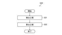
- the rate of change acquisition step (step S20) includes, for example, a detection step (step S21) and a calculation step (step S22).
- step S21 physical quantity data indicating the physical quantity of the fluid corresponding to each of a plurality of times within the determination period is detected (step S21).
- step S21 in the state determination device 100, the pressure sensor 108 detects, as physical quantity data, pressure values indicating pressures, which are physical quantities of the fluid, corresponding to a plurality of times within the determination period.
- the pressure value detected by the pressure sensor 108 is acquired by the sensor information acquisition unit 308.
- the sensor information acquisition unit 308 acquires, for example, a pressure value as shown in the graph of FIG. 9 as the pressure within the supply pipe line 102.
- a rate of change (rate of pressure change), which is the amount of change in the pressure value per unit time, is calculated based on the pressure value, which is the physical quantity data detected in the detection step (step S22).
- the pressure change rate calculation unit 318 calculates the pressure change rate based on the pressure value acquired by the sensor information acquisition unit 308 (that is, the pressure value detected by the pressure sensor 108 in step S21).
- the rate of pressure change can also be referred to as the rate of decrease in the pressure value per unit time.
- the pressure change rate calculation unit 318 performs a conversion process to make the change rate constant so that it can be compared with a predetermined threshold (for example, a constant threshold).
- Constantizing the rate of change means making the rate of change approach a predetermined constant, for example, making the slope of the rate of change approach a straight line.
- the conversion process is not limited and includes any process as long as the rate of change can be made constant.
- the conversion process includes, for example, setting an appropriate range so that the rate of change is approximately constant, converting the rate of change into a constant so that it can be compared with a single threshold, and In order to eliminate false detections, this includes excluding ranges that are difficult to stabilize, and performing time-sharing and arithmetic processing to eliminate outliers and variations.
- the rate of change is made constant by logarithmically converting at least one of the physical quantity data and the time data indicating the elapsed time from the start of the determination period.
- FIG. 11 is a semi-logarithmic graph in which the vertical axis is the logarithmic axis of pressure values and the horizontal axis is the time axis.
- the pressure value is plotted on the logarithmic axis for the pressure change (transition) shown in FIG.
- This is a graph in which conversion processing is performed so that the rate of change of physical quantity data is approximately constant.
- logarithmic transformation is shown as the conversion process in FIG. 11, as long as the rate of change can be made constant, the time interval (horizontal axis) may be changed as appropriate, and the interval between physical quantities (vertical axis) may be changed as appropriate. Alternatively, these may be combined and changed as appropriate. That is, the unit intervals of each parameter (time and physical quantity) may be equal intervals, logarithmic intervals, or any predetermined intervals, and can be selected depending on the characteristics of the rate of change.
- the state determination device 100 prepares a constantization pattern of several combinations of time intervals (horizontal axis) and physical quantity intervals (vertical axis) that can constantize the rate of change, and calculates the physical quantity data of the supply pipe 102 during the determination period. When detected, the physical quantity data may be applied to a constantization pattern to constantize the rate of change.
- the flow rate of the supply pipe 102 may be used as the physical quantity data.
- the state determination device 100 in FIG. 5 is provided with a flow rate sensor that detects the flow rate of the fluid flowing through the supply pipe line 102, and the sensor information acquisition unit 308 acquires the detected value of this flow rate sensor.
- the calculation step may include a process of converting the approximately constant rate of change into a constant in order to facilitate comparison with a predetermined threshold (constant).
- FIG. 12 is a graph in which the rates of change of a plurality of data series that are approximately constant as shown in the graph of FIG. 11 are converted so that the slope A of each data series becomes a constant, as will be described later.
- the rate of change can be expressed as a slope A (constant).
- FIG. 12 it can be seen that the slope A is divided into two point sets depending on its magnitude.
- the two point sets are formed by the state (open state and closed state) of the endoscope conduit 10A being reflected in the magnitude of the rate of change (inclination A) of the pressure value of the supply conduit 102. Conversely, if a set of two points can be formed according to the magnitude of the rate of change (inclination A) in the pressure value of the supply conduit 102, the state of the endoscope conduit 10A (open state and closed state) can be determined. .
- FIG. 12 shows a case where the approximately constant rate of change shown in the graph of FIG. 11 is converted into a constant by performing a conversion process. Preferred embodiments are shown below.
- the pressure change rate calculation unit 318 applies the following preferred aspects singly or in combination.
- the rate of change can be calculated for the graph of FIG. 11 based on time-divided data obtained by time-dividing the physical quantity data for each time period.
- the physical quantity data does not need to be continuous in time; as long as it is acquired at intervals long enough to obtain the rate of change, the constant rate of change shown in FIG. 12 can be obtained. .
- the rate of change can be calculated by linearly approximating the time-shared data to the graph of FIG. 11. If linear approximation is possible, the slope A of the rate of change can be obtained as a constant.
- the rate of change can be calculated for the graph of FIG. 11 based on the slope between two points included in the time-sharing data. Since it is a slope between two points, the slope A of the rate of change can be obtained as a constant.
- the rate of change can be calculated by performing linear approximation to the graph of FIG. 11 based on the residual of the time-sharing data. If linear approximation is possible, the slope A of the rate of change can be obtained as a constant.
- the rate of change can be calculated by performing linear approximation to the graph of FIG. 11 such that the sum of squares of the residuals of the time-sharing data is minimized.
- the graph shown in FIG. 12 shows the result of linear approximation to the graph of FIG. 11 in which the sum of squares of the residual errors of the time-sharing data is minimized. It can be understood that the slope A of the rate of change can be obtained as a constant.
- the calculation step may include, for example, (5) an outlier exclusion step of identifying outliers included in the physical quantity data based on the physical quantity data after the conversion process and excluding the outliers from the physical quantity data. preferable.
- the maximum outlier value from the pressure value in the same data series is Preferably, values and minimum values are excluded.
- outliers from the data series when converting from a semilogarithmic graph in which the vertical axis is pressure value and the horizontal axis is time in Figure 11 to the graph with slope A of the rate of change shown in Figure 12, it is possible to correct The slope A of the rate of change can be obtained, and as a result, false detection can be suppressed.
- the calculation step includes (6) a dispersion determination step of determining the degree of dispersion of the physical quantity data based on the physical quantity data after the conversion process has been performed.
- a threshold value is set in advance, and it can be determined whether the physical quantity data is in error based on the threshold value. If it is an error, it is possible to identify the cause and re-measure to prevent false positives.
- the determination period is divided into D1, D2, and D3, and within the range of each divided period D1, D2, and D3, conversions (1) to (6) in the calculation step described above
- conversion processing may be performed such that the slope A of the rate of change of the data series is a constant.
- the determination period is a period after a preset exclusion period has elapsed since the fluid supply was stopped.
- the exclusion period D4 is a certain period after the solenoid valve is opened in step S14.
- the exclusion period D4 is a certain period after the solenoid valve is opened in step S14.
- this fixed period there is a change point in the change (transition) of the pressure value, and the position of the change point varies depending on the model of the endoscope and the opening state of the duct.
- pressure values for this certain period it is possible to exclude ranges in which physical quantity data are difficult to stabilize. Therefore, when performing conversion processing such that the slope A of the pressure change rate of each data series is a constant, the correct slope A can be obtained, and as a result, false detection can be suppressed.
- the determination step (step S30) is a step of determining the state of the endoscope channel, and determines whether the endoscope channel is in an open state or a closed state.
- the determination step (step S30) includes a change rate information acquisition step (step S31) for acquiring the calculated change rate, a comparison step (step S32) for comparing the change rate with a threshold value, and a step in which the endoscope conduit 10A is It includes an open state determining step (step S33) for determining that the endoscope channel 10A is in the open state, and a closed state determining step (step S34) for determining that the endoscope channel 10A is in the closed state.
- the threshold value used in the comparison step is an example of a determination threshold value that indicates opening or occlusion of the endoscopic channel.
- the change rate information acquisition step acquires the change rate calculated in the change rate acquisition step (step S20) (step S31).
- step S31 in the state determining device 100, the endoscope channel state determining unit 320 acquires the rate of change (inclination A) calculated by the rate of pressure change calculating unit 318.
- the comparison step of comparing the rate of change and the threshold value compares the rate of change (slope A) acquired in step S31 with a preset threshold value, and determines whether the rate of change (slope A) satisfies the threshold value (step S32).
- the endoscope channel state determination unit 320 compares the acquired rate of change (inclination A) with a threshold value, and determines whether the threshold value is satisfied.
- the process proceeds to step S33 and determines that the endoscope channel 10A is in an open state.
- step S34 determines that the endoscope channel 10A is in a closed state.
- the result information of the determination process is sent to the control unit 316, for example.
- the control unit 316 stores the result information in the storage unit 314 and displays it on the display operation panel 206 via the input/output I/F.
- the determination process ends as described above.
- FIG. 14 is a diagram for explaining the comparison between the rate of change and the threshold value, and is a diagram in which the threshold value and the state of the endoscope channel are added to FIG. 12. Note that the vertical axis in FIG. 14 indicates the absolute value of the rate of change (inclination A).
- the endoscope duct state determining unit 320 determines the state of the endoscope duct (open state and closed state) by comparing the rate of change (inclination A) with a predetermined threshold value. For example, in the example of FIG. 14, if the rate of change (inclination A) is larger than the threshold value, it is determined that the threshold value is satisfied, and the endoscope channel state determination unit 320 determines that the state of the endoscope channel 10A is in the open state. judge. On the other hand, if the rate of change (inclination A) is smaller than the threshold, the endoscope channel state determining unit 320 determines that the threshold is not satisfied and determines that the state of the endoscope channel 10A is a closed state.
- the time-divided physical quantity data is set as a constant called slope A, and this constant is compared with a predetermined threshold (constant), making it easy to detect abnormal points such as waveform disturbances and outliers. becomes easier. Furthermore, it is also possible to exclude the influence of initial value variations and the like. It is possible to accurately determine the state of the endoscope channel.
- FIG. 14 describes the case where one threshold value is set in advance, the occlusion determination threshold value for determining the occlusion state and the occlusion determination threshold value for determining the open state may be set separately.
- the threshold value in FIG. 14 serves both as a threshold value for determining occlusion and a threshold value for determining opening.
- the physical quantity of the fluid in the present invention is the pressure or flow rate of the fluid, but the physical quantity of the fluid is not limited to this, for example, the physical quantity of the fluid may be the temperature of the fluid.
- a certain aspect (first modification) and an aspect (second modification) in which the physical quantity of the fluid is the flow velocity (kinetic energy) of the fluid may be adopted.
- a temperature sensor (not shown) provided in the supply pipeline 102 detects a temporal change in the temperature of the fluid flowing through the supply pipeline 102, and the temperature change is the amount of change in temperature per unit time.
- the state of patency or occlusion of the endoscopic channel is determined based on the rate.
- the temporal change in the temperature of the fluid detected by the temperature sensor is preferably such that the temperature of the fluid gradually decreases over time, and the rate of temperature change is the rate of decrease in temperature per unit time. Further, when the temperature of the fluid gradually increases over time, the rate of temperature change is the rate of increase in temperature per unit time.
- a flow velocity sensor (not shown) provided in the supply pipeline 102 detects a temporal change in the velocity of the fluid flowing through the supply pipeline 102, and the velocity change is the amount of change in velocity per unit time.
- the state of patency or occlusion of the endoscopic channel is determined based on the rate.
- the temporal change in the fluid velocity detected by the flow velocity sensor is preferably such that the fluid velocity gradually increases over time, and the velocity change rate is the rate of increase in the flow velocity per unit time. Further, when the velocity of the fluid gradually decreases over time, the velocity change rate is the rate of decrease in the flow velocity per unit time.
Landscapes
- Health & Medical Sciences (AREA)
- Life Sciences & Earth Sciences (AREA)
- Surgery (AREA)
- Engineering & Computer Science (AREA)
- Biomedical Technology (AREA)
- Molecular Biology (AREA)
- Pathology (AREA)
- Radiology & Medical Imaging (AREA)
- Nuclear Medicine, Radiotherapy & Molecular Imaging (AREA)
- Biophysics (AREA)
- Physics & Mathematics (AREA)
- Heart & Thoracic Surgery (AREA)
- Medical Informatics (AREA)
- Optics & Photonics (AREA)
- Animal Behavior & Ethology (AREA)
- General Health & Medical Sciences (AREA)
- Public Health (AREA)
- Veterinary Medicine (AREA)
- Mechanical Engineering (AREA)
- Endoscopes (AREA)
- Signal Processing (AREA)
Priority Applications (4)
| Application Number | Priority Date | Filing Date | Title |
|---|---|---|---|
| CN202380029189.4A CN118900661A (zh) | 2022-03-22 | 2023-03-10 | 内窥镜管路的状态判定方法、内窥镜管路的状态判定装置及内窥镜清洗消毒装置 |
| JP2024509995A JPWO2023181983A1 (https=) | 2022-03-22 | 2023-03-10 | |
| DE112023000686.5T DE112023000686T5 (de) | 2022-03-22 | 2023-03-10 | Zustandsbestimmungsverfahren für endoskop-rohrleitung, zustandsbestimmungsvorrichtung für endoskop-rohrleitung und endoskop-wasch- und desinfektionsvorrichtung |
| US18/889,335 US20250009204A1 (en) | 2022-03-22 | 2024-09-18 | State determination method for endoscope pipe line, state determination device for endoscope pipe line, and endoscope washing and disinfection device |
Applications Claiming Priority (2)
| Application Number | Priority Date | Filing Date | Title |
|---|---|---|---|
| JP2022045702 | 2022-03-22 | ||
| JP2022-045702 | 2022-03-22 |
Related Child Applications (1)
| Application Number | Title | Priority Date | Filing Date |
|---|---|---|---|
| US18/889,335 Continuation US20250009204A1 (en) | 2022-03-22 | 2024-09-18 | State determination method for endoscope pipe line, state determination device for endoscope pipe line, and endoscope washing and disinfection device |
Publications (1)
| Publication Number | Publication Date |
|---|---|
| WO2023181983A1 true WO2023181983A1 (ja) | 2023-09-28 |
Family
ID=88101289
Family Applications (1)
| Application Number | Title | Priority Date | Filing Date |
|---|---|---|---|
| PCT/JP2023/009248 Ceased WO2023181983A1 (ja) | 2022-03-22 | 2023-03-10 | 内視鏡管路の状態判定方法、内視鏡管路の状態判定装置、及び内視鏡洗浄消毒装置 |
Country Status (5)
| Country | Link |
|---|---|
| US (1) | US20250009204A1 (https=) |
| JP (1) | JPWO2023181983A1 (https=) |
| CN (1) | CN118900661A (https=) |
| DE (1) | DE112023000686T5 (https=) |
| WO (1) | WO2023181983A1 (https=) |
Cited By (2)
| Publication number | Priority date | Publication date | Assignee | Title |
|---|---|---|---|---|
| WO2025134240A1 (ja) * | 2023-12-19 | 2025-06-26 | 晴洋 井上 | 制御装置、内視鏡システム、及び体内の圧力測定方法 |
| WO2025166882A1 (zh) * | 2024-02-06 | 2025-08-14 | 深圳市博为医疗机器人有限公司 | 内窥镜的自动清洗系统 |
Families Citing this family (1)
| Publication number | Priority date | Publication date | Assignee | Title |
|---|---|---|---|---|
| CN120859415B (zh) * | 2025-09-26 | 2025-11-28 | 北京中研海康科技有限公司 | 乳管镜检查中导管内压力实时监测与控制方法及系统 |
Citations (7)
| Publication number | Priority date | Publication date | Assignee | Title |
|---|---|---|---|---|
| JP2007125385A (ja) * | 2005-10-31 | 2007-05-24 | Ethicon Inc | 内視鏡内の流路に流動を与えるための装置および方法 |
| JP2009514611A (ja) * | 2005-11-02 | 2009-04-09 | ミンテック コーポレーション | 内視鏡再処理装置の接続装置、並びに接続方法 |
| JP2009226193A (ja) * | 2008-02-27 | 2009-10-08 | Olympus Medical Systems Corp | 内視鏡洗浄消毒装置 |
| JP2012504431A (ja) * | 2008-09-30 | 2012-02-23 | プリンストン トレード アンド テクノロジー インコーポレイテッド | 液体及び気体の流動を使用して内視鏡のチャネルなどの通路を洗浄する装置及び方法 |
| WO2015068515A1 (ja) * | 2013-11-08 | 2015-05-14 | オリンパスメディカルシステムズ株式会社 | 内視鏡リプロセス装置 |
| JP2016209461A (ja) * | 2015-05-13 | 2016-12-15 | オリンパス株式会社 | 気腹システム |
| US20200187768A1 (en) * | 2018-02-09 | 2020-06-18 | Gyrus Acmi, Inc. D/B/A Olympus Surgical Technologies America | Endoscope unclogging system and method |
Family Cites Families (3)
| Publication number | Priority date | Publication date | Assignee | Title |
|---|---|---|---|---|
| JP4633274B2 (ja) | 2000-02-17 | 2011-02-16 | オリンパス株式会社 | 内視鏡洗滌消毒装置 |
| JP4652844B2 (ja) | 2005-02-24 | 2011-03-16 | オリンパスメディカルシステムズ株式会社 | 内視鏡洗滌消毒装置及び内視鏡洗滌消毒方法 |
| DE102008026445A1 (de) | 2008-06-03 | 2009-12-10 | Olympus Winter & Ibe Gmbh | Verfahren zur Prüfung der Durchgängigkeit eines Endoskopkanales und Endoskopwaschmaschine dafür |
-
2023
- 2023-03-10 JP JP2024509995A patent/JPWO2023181983A1/ja active Pending
- 2023-03-10 WO PCT/JP2023/009248 patent/WO2023181983A1/ja not_active Ceased
- 2023-03-10 CN CN202380029189.4A patent/CN118900661A/zh active Pending
- 2023-03-10 DE DE112023000686.5T patent/DE112023000686T5/de active Pending
-
2024
- 2024-09-18 US US18/889,335 patent/US20250009204A1/en active Pending
Patent Citations (7)
| Publication number | Priority date | Publication date | Assignee | Title |
|---|---|---|---|---|
| JP2007125385A (ja) * | 2005-10-31 | 2007-05-24 | Ethicon Inc | 内視鏡内の流路に流動を与えるための装置および方法 |
| JP2009514611A (ja) * | 2005-11-02 | 2009-04-09 | ミンテック コーポレーション | 内視鏡再処理装置の接続装置、並びに接続方法 |
| JP2009226193A (ja) * | 2008-02-27 | 2009-10-08 | Olympus Medical Systems Corp | 内視鏡洗浄消毒装置 |
| JP2012504431A (ja) * | 2008-09-30 | 2012-02-23 | プリンストン トレード アンド テクノロジー インコーポレイテッド | 液体及び気体の流動を使用して内視鏡のチャネルなどの通路を洗浄する装置及び方法 |
| WO2015068515A1 (ja) * | 2013-11-08 | 2015-05-14 | オリンパスメディカルシステムズ株式会社 | 内視鏡リプロセス装置 |
| JP2016209461A (ja) * | 2015-05-13 | 2016-12-15 | オリンパス株式会社 | 気腹システム |
| US20200187768A1 (en) * | 2018-02-09 | 2020-06-18 | Gyrus Acmi, Inc. D/B/A Olympus Surgical Technologies America | Endoscope unclogging system and method |
Cited By (2)
| Publication number | Priority date | Publication date | Assignee | Title |
|---|---|---|---|---|
| WO2025134240A1 (ja) * | 2023-12-19 | 2025-06-26 | 晴洋 井上 | 制御装置、内視鏡システム、及び体内の圧力測定方法 |
| WO2025166882A1 (zh) * | 2024-02-06 | 2025-08-14 | 深圳市博为医疗机器人有限公司 | 内窥镜的自动清洗系统 |
Also Published As
| Publication number | Publication date |
|---|---|
| DE112023000686T5 (de) | 2024-11-14 |
| US20250009204A1 (en) | 2025-01-09 |
| JPWO2023181983A1 (https=) | 2023-09-28 |
| CN118900661A (zh) | 2024-11-05 |
Similar Documents
| Publication | Publication Date | Title |
|---|---|---|
| WO2023181983A1 (ja) | 内視鏡管路の状態判定方法、内視鏡管路の状態判定装置、及び内視鏡洗浄消毒装置 | |
| JP4504198B2 (ja) | 内視鏡洗滌消毒装置および内視鏡洗滌消毒方法 | |
| US7879289B2 (en) | Automated endoscope reprocessor self-disinfection connection | |
| US7686761B2 (en) | Method of detecting proper connection of an endoscope to an endoscope processor | |
| AU2008296521B2 (en) | Automated endoscope reprocessor | |
| WO2010010787A1 (ja) | 内視鏡自動洗浄消毒装置 | |
| CA2800400C (en) | An apparatus to decontaminate equipment containing internal channels | |
| EP1779770A1 (en) | Apparatus and method for providing flow to endoscope channels | |
| AU2006222761B2 (en) | Method of detecting connection of test port on an endoscope | |
| AU2011258880A1 (en) | An apparatus to decontaminate equipment containing internal channels | |
| AU2006201276A1 (en) | Automated endoscope reprocessor connection integrity testing via liquid suction | |
| WO2013031388A1 (ja) | 内視鏡処理装置 | |
| CN102264274B (zh) | 用于内窥镜清洗机的测试设备 | |
| JP7713525B2 (ja) | 灌流状態検出装置の作動方法、灌流状態検出装置及び内視鏡システム | |
| US20240260823A1 (en) | Systems and methods for the identification, evaluation, and/or closed-loop reprocessing of lumens | |
| JP7654572B2 (ja) | 可変オリフィス装置を有する再処理装置 | |
| JPH07184840A (ja) | 内視鏡カバー気密検査装置 | |
| AU2012211468B2 (en) | Automated endoscope reprocessor self-disinfection connection |
Legal Events
| Date | Code | Title | Description |
|---|---|---|---|
| 121 | Ep: the epo has been informed by wipo that ep was designated in this application |
Ref document number: 23774582 Country of ref document: EP Kind code of ref document: A1 |
|
| ENP | Entry into the national phase |
Ref document number: 2024509995 Country of ref document: JP Kind code of ref document: A |
|
| WWE | Wipo information: entry into national phase |
Ref document number: 112023000686 Country of ref document: DE |
|
| WWE | Wipo information: entry into national phase |
Ref document number: 202380029189.4 Country of ref document: CN |
|
| 122 | Ep: pct application non-entry in european phase |
Ref document number: 23774582 Country of ref document: EP Kind code of ref document: A1 |