WO2023181983A1 - Endoscope conduit condition determination method, endoscope conduit condition determination device, and endoscope cleaning/disinfecting device - Google Patents
Endoscope conduit condition determination method, endoscope conduit condition determination device, and endoscope cleaning/disinfecting device Download PDFInfo
- Publication number
- WO2023181983A1 WO2023181983A1 PCT/JP2023/009248 JP2023009248W WO2023181983A1 WO 2023181983 A1 WO2023181983 A1 WO 2023181983A1 JP 2023009248 W JP2023009248 W JP 2023009248W WO 2023181983 A1 WO2023181983 A1 WO 2023181983A1
- Authority
- WO
- WIPO (PCT)
- Prior art keywords
- endoscope
- change
- rate
- state
- fluid
- Prior art date
Links
- 238000000034 method Methods 0.000 title claims abstract description 87
- 238000004140 cleaning Methods 0.000 title claims abstract description 59
- 230000000249 desinfective effect Effects 0.000 title claims abstract description 12
- 230000008859 change Effects 0.000 claims abstract description 162
- 239000012530 fluid Substances 0.000 claims abstract description 109
- 230000008569 process Effects 0.000 claims description 45
- 238000006243 chemical reaction Methods 0.000 claims description 28
- 238000001514 detection method Methods 0.000 claims description 14
- 230000007717 exclusion Effects 0.000 claims description 8
- XLYOFNOQVPJJNP-UHFFFAOYSA-N water Substances O XLYOFNOQVPJJNP-UHFFFAOYSA-N 0.000 description 66
- 239000007788 liquid Substances 0.000 description 30
- 238000003780 insertion Methods 0.000 description 15
- 230000037431 insertion Effects 0.000 description 15
- 238000012545 processing Methods 0.000 description 10
- 230000007704 transition Effects 0.000 description 10
- 230000007423 decrease Effects 0.000 description 8
- 238000010586 diagram Methods 0.000 description 7
- 238000005286 illumination Methods 0.000 description 7
- 238000004659 sterilization and disinfection Methods 0.000 description 7
- 239000000645 desinfectant Substances 0.000 description 5
- 239000006185 dispersion Substances 0.000 description 4
- 238000012986 modification Methods 0.000 description 4
- 230000004048 modification Effects 0.000 description 4
- 230000002123 temporal effect Effects 0.000 description 4
- 238000003825 pressing Methods 0.000 description 3
- 238000013459 approach Methods 0.000 description 2
- 230000006870 function Effects 0.000 description 2
- 238000012544 monitoring process Methods 0.000 description 2
- 239000000758 substrate Substances 0.000 description 2
- 238000011144 upstream manufacturing Methods 0.000 description 2
- 238000009423 ventilation Methods 0.000 description 2
- 241000894006 Bacteria Species 0.000 description 1
- LFQSCWFLJHTTHZ-UHFFFAOYSA-N Ethanol Chemical compound CCO LFQSCWFLJHTTHZ-UHFFFAOYSA-N 0.000 description 1
- 230000002159 abnormal effect Effects 0.000 description 1
- 230000005856 abnormality Effects 0.000 description 1
- 238000003491 array Methods 0.000 description 1
- 238000004891 communication Methods 0.000 description 1
- 230000000295 complement effect Effects 0.000 description 1
- 230000007797 corrosion Effects 0.000 description 1
- 238000005260 corrosion Methods 0.000 description 1
- 210000001035 gastrointestinal tract Anatomy 0.000 description 1
- 238000003384 imaging method Methods 0.000 description 1
- 210000002429 large intestine Anatomy 0.000 description 1
- 230000003902 lesion Effects 0.000 description 1
- 239000004973 liquid crystal related substance Substances 0.000 description 1
- 230000015654 memory Effects 0.000 description 1
- 239000002184 metal Substances 0.000 description 1
- 229910044991 metal oxide Inorganic materials 0.000 description 1
- 150000004706 metal oxides Chemical class 0.000 description 1
- 239000004065 semiconductor Substances 0.000 description 1
- 229910001220 stainless steel Inorganic materials 0.000 description 1
- 239000010935 stainless steel Substances 0.000 description 1
- 210000002784 stomach Anatomy 0.000 description 1
- 238000012360 testing method Methods 0.000 description 1
- 230000009466 transformation Effects 0.000 description 1
Images


Classifications
-
- A—HUMAN NECESSITIES
- A61—MEDICAL OR VETERINARY SCIENCE; HYGIENE
- A61B—DIAGNOSIS; SURGERY; IDENTIFICATION
- A61B1/00—Instruments for performing medical examinations of the interior of cavities or tubes of the body by visual or photographical inspection, e.g. endoscopes; Illuminating arrangements therefor
- A61B1/012—Instruments for performing medical examinations of the interior of cavities or tubes of the body by visual or photographical inspection, e.g. endoscopes; Illuminating arrangements therefor characterised by internal passages or accessories therefor
- A61B1/018—Instruments for performing medical examinations of the interior of cavities or tubes of the body by visual or photographical inspection, e.g. endoscopes; Illuminating arrangements therefor characterised by internal passages or accessories therefor for receiving instruments
-
- A—HUMAN NECESSITIES
- A61—MEDICAL OR VETERINARY SCIENCE; HYGIENE
- A61B—DIAGNOSIS; SURGERY; IDENTIFICATION
- A61B1/00—Instruments for performing medical examinations of the interior of cavities or tubes of the body by visual or photographical inspection, e.g. endoscopes; Illuminating arrangements therefor
- A61B1/12—Instruments for performing medical examinations of the interior of cavities or tubes of the body by visual or photographical inspection, e.g. endoscopes; Illuminating arrangements therefor with cooling or rinsing arrangements
Definitions
- the present invention relates to a method for determining the state of an endoscope conduit, a device for determining the state of an endoscope conduit, and an endoscope cleaning/disinfecting device.
- the present invention relates to a method for determining the state of an endoscope conduit, an apparatus for determining the state of an endoscope conduit, and an endoscope cleaning and disinfecting device for determining whether the state is open or blocked.
- An endoscope cleaning and disinfecting device is known as a device for cleaning and disinfecting used endoscopes.
- An endoscope cleaning and disinfecting device typically performs cleaning and disinfection through multiple steps such as cleaning, disinfection, and rinsing.
- cleaning liquid and disinfectant solution are also supplied to multiple pipes inside the endoscope, such as air and water supply pipes, suction pipes, treatment instrument insertion pipes, etc. This will clean and disinfect.
- air and water supply pipes such as air and water supply pipes, suction pipes, treatment instrument insertion pipes, etc.
- suction pipes such as suction pipes
- treatment instrument insertion pipes etc.
- This will clean and disinfect.
- the duct of the endoscope is clogged, it is difficult for the cleaning liquid and disinfectant to be supplied to the duct, so that sufficient cleaning and disinfection are not performed.
- a test is performed to determine whether the duct of the endoscope is open or blocked.
- Patent Document 1 discloses that by supplying fluid into the pipe line of an endoscope, measuring the pressure or flow rate of the fluid flowing inside the pipe line, and calculating the comparison between the measured value and the set value, It is described that the clogging situation of the endoscope is detected.
- Patent Document 2 discloses that by sending pressurized fluid to a channel in an endoscope, monitoring the back pressure, and monitoring the time until the back pressure drops to a predetermined value, the channel is connected and opened. It describes how to determine whether the connection is connected or not.
- Patent Document 3 describes that a series of pressure pulses is applied to an endoscope conduit, and the patency of the endoscope conduit is tested based on the maximum and minimum values of the pressure pulses.
- Patent Document 4 describes that a fluid is supplied into an internal conduit of an endoscope and an abnormality is determined by comparing the pressure or flow rate of the fluid with a threshold value.
- the present invention has been made in view of the above circumstances, and provides a method for determining the state of an endoscope duct, which can determine whether the endoscope duct is open or blocked with high accuracy, and an endoscope.
- An object of the present invention is to provide a conduit condition determination device and an endoscope cleaning/disinfecting device.
- the method for determining the state of an endoscope conduit includes a supply step of supplying pressurized fluid to an endoscope conduit, and a unit time of the physical quantity of the fluid during a determination period after stopping the supply of the fluid.
- the present invention includes a change rate acquisition step of acquiring a change rate that is the amount of change per hit, and a determination step of determining whether the endoscopic channel is open or blocked based on the change rate acquired in the change rate acquisition step.
- the physical quantity is the pressure or flow rate of the fluid.
- the supply of fluid is stopped after the endoscope conduit is filled with fluid in the supply step.
- the rate of change acquisition step includes a detection step of detecting physical quantity data indicating the physical quantity of the fluid corresponding to each of a plurality of times within the determination period; and a calculation step of calculating a rate of change based on the physical quantity data obtained.
- the calculation step includes a conversion process that converts the rate of change into a constant.
- the calculation step includes, as a conversion process, logarithmically converting at least one of the physical quantity data and the time data indicating the elapsed time from the start of the determination period. By doing this, the rate of change is made constant.
- the calculation step calculates the rate of change based on time-sharing data obtained by time-sharing the physical quantity data.
- the calculation step calculates the rate of change by performing linear approximation of the time-shared data.
- the calculation step calculates the rate of change based on the slope between two points included in the time-shared data.
- the calculation step calculates the rate of change by performing linear approximation based on the residual of the time-sharing data.
- the calculation step calculates the rate of change by performing a linear approximation that minimizes the sum of squares of residual errors of the time-shared data.
- an outlier included in the physical quantity data is identified based on the physical quantity data after conversion processing is performed, and the outlier is excluded from the physical quantity data. Includes an exclusion process.
- the method for determining the state of an endoscope conduit according to the thirteenth aspect includes a dispersion determining step of determining the degree of dispersion of the physical quantity data based on the physical quantity data after the conversion process has been performed.
- the determination step is performed by comparing the rate of change made constant by the conversion process with a determination threshold value indicating whether the endoscope conduit is open or blocked. I do.
- the determination period is a period after a preset exclusion period has elapsed after the fluid supply was stopped.
- a state determination device for an endoscope conduit includes a supply conduit connected to an endoscope conduit and supplying pressurized fluid to the endoscope conduit, and a physical quantity for detecting a physical quantity of the fluid.
- the processor includes a detection sensor and a processor, and the processor determines the amount of change in the physical quantity of the fluid per unit time in a determination period after stopping the supply of the supplied fluid, based on the physical quantity of the fluid detected by the physical quantity detection sensor. A rate of change is obtained, and the state of the endoscope channel is determined based on the calculated rate of change.
- the physical quantity is the pressure or flow rate of the fluid.
- the supply of fluid is stopped after the endoscope channel is filled with fluid.
- the processor detects physical quantity data indicating physical quantities of the fluid corresponding to a plurality of times within the determination period, and calculates a rate of change based on the detected physical quantity data. calculate.
- the processor performs conversion processing to make the rate of change constant.
- the endoscope cleaning and disinfecting device includes the endoscope conduit state determination device described above.
- FIG. 1 is an overall view of an endoscope that is cleaned by an endoscope cleaning device according to an embodiment.
- FIG. 2 is a perspective view of the main parts showing the distal end side of the insertion section of the endoscope.
- FIG. 3 is a schematic diagram of the cleaning device.
- FIG. 4 is a block diagram of the controller.
- FIG. 5 shows a connection configuration between the state determining device and the endoscope channel of the endoscope.
- FIG. 6 is a flowchart of a method for determining the state of an endoscope channel.
- FIG. 7 is a flowchart of the supply process.
- FIG. 8 is a graph showing changes in pressure within the supply pipe line during the supply process shown in FIG.
- FIG. 9 is a graph of actual pressure values versus the determination period of FIG.
- FIG. 8 is a graph showing changes in pressure within the supply pipe line during the supply process shown in FIG.
- FIG. 9 is a graph of actual pressure values versus the determination period of FIG. FIG.
- FIG. 10 is a flowchart of the change rate acquisition process.
- FIG. 11 is a semi-logarithmic graph in which the horizontal axis is the time axis and the vertical axis is the logarithmic axis of pressure.
- FIG. 12 is a graph obtained by converting the graph shown in FIG. 11 so that the rate of change becomes a constant.
- FIG. 13 is a flowchart of the determination process.
- FIG. 14 is a diagram for explaining a comparison between the rate of change and the threshold value.
- FIG. 1 is an overall view of an endoscope 10 in which the state of the conduit is determined by the endoscope conduit state determination method according to the embodiment, and particularly schematically shows the conduit configuration of the endoscope 10. There is. First, the configuration of the endoscope 10 will be briefly described with reference to FIG.
- the endoscope 10 includes an insertion section 12 that is inserted into a patient's lumen, for example, into a gastrointestinal tract such as the stomach or large intestine, and a hand operation section 14 that is connected to the insertion section 12. Equipped with A universal cable 16 is connected to the hand operation unit 14, and an LG connector 18 is provided at the tip of the universal cable 16.
- the LG connector 18 By connecting the LG connector 18 to the light source device 20, illumination light is transmitted to the illumination windows 22, 22 (see FIG. 2).
- the LG connector 18 has an electrical connector (not shown), and this electrical connector is detachably connected to a processor (not shown). Note that the LG connector 18 is connected to a conduit 24 for air and water supply and a conduit 26 for suction.
- the hand operation unit 14 is provided with an air/water supply button 28, a suction button 30, and a shutter button 32 in parallel, as well as a pair of angle knobs (not shown) and a forceps insertion port 34.
- FIG. 2 is a perspective view of the main parts showing the distal end side of the insertion section 12.
- the insertion section 12 includes a distal end section 36, a curved section 38, and a flexible section 40. Curving is controlled remotely. Thereby, the distal end surface 42 of the distal end portion 36 can be directed in a desired direction.
- the distal end surface 42 of the distal end portion 36 is provided with an observation window 44, illumination windows 22, 22, an air/water supply nozzle 46, and a forceps port 48.
- An imaging device (not shown) is arranged behind the observation window 44 (on the proximal end side).
- the image sensor is supported by a substrate (not shown), and a signal cable is connected to the substrate.
- the signal cable is inserted through the insertion section 12, the hand-operated section 14, and the universal cable 16 in FIG. 1, and is extended to the electrical connector and connected to the processor. Therefore, the observed image taken in from the observation window 44 in FIG. 2 is focused on the light receiving surface of the image sensor and converted into an electrical signal, and this electrical signal is outputted to the processor via the signal cable to produce a video signal.
- the observed image is displayed on a monitor (not shown) connected to the processor.
- a CCD (Charge Coupled Device) type image sensor or a CMOS (Complementary Metal Oxide Semiconductor) type image sensor is used as the image sensor.
- An output end of a light guide (not shown) is provided behind (on the proximal end side) of the illumination windows 22, 22.
- This light guide is inserted into the insertion section 12, the hand operation section 14, and the universal cable 16 in FIG. Then, the incident end of the light guide is connected to the light guide rod 50 of the LG connector 18. Therefore, by connecting the light guide rod 50 of the LG connector 18 to the light source device 20, the illumination light emitted from the light source device 20 is transmitted to the illumination windows 22, 22 via the light guide, and from the illumination windows 22, 22. irradiated.
- the above is the schematic configuration of the endoscope 10.
- an air/water supply conduit 52 is inserted into the insertion portion 12 of the endoscope 10, and an air/water supply nozzle 46 is connected to an opening on the distal end side of the air/water supply conduit 52.
- the base end side of the air and water supply pipe 52 is branched into an air supply pipe 54 and a water supply pipe 56, and the base end side of these pipes is connected to a cylinder 58 for air and water supply provided in the hand operation unit 14. communicated with the inside of the That is, one end of each of the air supply pipe 54 and the water supply pipe 56 is communicated with the interior of the cylinder 58, and the other end of each is joined to the air and water supply pipe 52, which is one pipe.
- the respective distal ends of the air supply pipe line 60 and the water supply pipe line 62 are communicated with each other, and the air/water supply button 28 is detachably attached.
- the air/water supply button 28 is protruded, the air supply pipe 54 and the air supply pipe 60 are communicated via the cylinder 58, and by pressing the air/water supply button 28, the water supply pipe 56 and the water supply pipe 62 are communicated with each other via the cylinder 58. are communicated via the cylinder 58.
- a ventilation hole (not shown) is formed in the air/water supply button 28, and the air supply pipe line 60 is communicated with the outside air through the ventilation hole.
- the air supply pipe line 60 and the water supply pipe line 62 are inserted into the universal cable 16 and extend toward the water supply connector 64 of the LG connector 18.
- a conduit 24 is detachably connected to the water supply connector 64 , and the tip of the conduit 24 is connected to a water storage tank 66 .
- the water supply pipe 62 is communicated below the liquid level of the water storage tank 66, and the air supply pipe 60 is communicated above the liquid level.
- An air conduit 68 is connected to the water supply connector 64, and this air conduit 68 communicates with the air supply conduit 60. Furthermore, the air pipe line 68 is communicated with an air pump 70 in the light source device 20 by connecting the LG connector 18 to the light source device 20 . Therefore, when the air pump 70 is driven to supply air, the air is supplied to the air supply pipe 60 via the air pipe 68. When the air and water supply button 28 is not operated, this air is released to the outside air through a vent hole (not shown) of the air and water supply button 28, but when the operator closes the vent hole, the air supply pipe 60 The air is supplied to the air supply pipe line 54, and the air is injected from the air and water supply nozzle 46.
- the air and water supply button 28 is pressed, the air supply line 60 and the air supply line 54 are cut off, so that the air supplied to the air line 68 is supplied above the liquid level of the water storage tank 66. .
- the internal pressure of the water storage tank 66 increases and water is sent to the water supply pipe 62.
- water is injected from the air/water supply nozzle 46 via the water supply pipe line 56. In this way, air or water is injected from the air/water supply nozzle 46 and is blown onto the observation window 44, thereby cleaning the observation window 44.
- a forceps channel 72 is inserted into the insertion section 12 of the endoscope 10, and a forceps port 48 is opened at the distal end side of the forceps channel 72.
- the side is branched into two pipe lines 72A and 72B, the proximal end side of one pipe line 72A is communicated with the forceps insertion port 34, and the proximal end side of the other pipe line 72B is communicated with the inside of the cylinder 74 for suction. be done. Therefore, when a treatment tool such as forceps is inserted through the forceps insertion port 34, the treatment tool can be taken out from the forceps port 48.
- the proximal end side of the suction conduit 76 is communicated, and the suction button 30 is attached.
- the suction button 30 is protruded, the suction line 76 is communicated with the outside air, and by pressing down the suction button 30, the suction line 76 and the forceps line 72 are communicated via the cylinder 74 and the line 72B. be done.
- the suction line 76 extends to a suction connector 78 of the LG connector 18, and by connecting the line 26 to this suction connector 78, it communicates with a suction device (not shown). Therefore, by pressing down the suction button 30 while the suction device is driven, the lesion or the like can be suctioned from the forceps port 48 through the forceps conduit 72.
- the endoscope 10 includes a plurality of air and water supply system pipes (air supply pipe 60, water supply pipe 62, cylinder 58, air supply pipe 54, water supply pipe 56) that constitute the air and water supply system. and an air/water supply pipe 52).
- the plurality of air and water supply system pipes are to be cleaned, and in order to clean the plurality of air and water supply system pipes, the air and water supply button 28 including the valve body is removable from the cylinder 58.
- a plurality of suction system conduits suction conduit 76, cylinder 74, conduit 72B, conduit 72A, and forceps conduit 72 constituting the suction system are provided.
- the plurality of suction system conduits are to be cleaned, and in order to clean the plurality of suction system conduits, the suction button 30 including the valve body is also removable from the cylinder 74.
- FIG. 4 is a block diagram showing a schematic configuration of the cleaning device 200.
- FIG. 4 shows a configuration related to cleaning the endoscope channel and determining the state of the endoscope channel, and the detailed configuration of the cleaning device 200 will not be described.
- the cleaning device 200 disinfects and cleans the air and water supply system conduit, the suction system conduit, and other conduits (these may be collectively referred to as an endoscope conduit) of the endoscope 10, and cleans the endoscope 10.
- the state of the pipeline can be determined.
- the cleaning device 200 includes a box-shaped device main body 202, a cleaning tank 204 and a display operation panel 206 provided at the top of the device main body 202.
- the cleaning tank 204 is a water tank with an open top, and accommodates the endoscope 10 after use.
- the cleaning tank 204 is made of a metal with excellent heat resistance and corrosion resistance, such as stainless steel, and can store a liquid such as a cleaning solution or a disinfectant solution.
- the display operation panel 206 includes a large number of buttons for various settings related to cleaning, disinfection, and status determination of the endoscope 10, and for instructing to start or stop cleaning and disinfection. Further, the display operation panel 206 includes, for example, a liquid crystal display, and displays various setting screens, the remaining time of each process, a warning message when a trouble occurs, and the like. The display operation panel 206 may be separated into a display panel and an operation panel.
- the display operation panel 206 is connected to the controller 208.
- Controller 208 receives instructions from display operation panel 206 and controls the entire cleaning apparatus 200 according to the instructions. Further, the controller 208 controls the display operation panel 206 to display various information.
- the cleaning device 200 includes a liquid storage tank 210, a liquid supply path 212 whose one end side is connected to the liquid storage tank 210, and a pump 214 and a solenoid valve 216 arranged in the liquid supply path 212.
- the liquid storage tank 210 stores a liquid 218 such as cleaning liquid, disinfectant liquid, or alcohol.
- Pump 214 sucks liquid 218 from liquid storage tank 210 and supplies liquid 218 to liquid supply path 212 .
- By switching the electromagnetic valve 216 between an open state and a closed state supply and stop of the liquid 218 to the liquid supply path 212 are switched.
- the cleaning device 200 includes an air pump 220, an air supply path 222 whose one end is connected to the air pump 220, and a filter 224 and a solenoid valve 226 arranged in the air supply path 222.
- the air pump 220 supplies air as a gas to the air supply path 222.
- the filter 224 is disposed downstream of the air pump 220 and upstream of the solenoid valve 226, and purifies the air by capturing bacteria in the air. By switching the electromagnetic valve 226 between an open state and a closed state, supply and stop of air to the air supply path 222 can be switched.
- the cleaning device 200 includes a main pipe 230, a check valve 232 and a pressure sensor 234 arranged in the main pipe 230.
- the check valve 232 prevents backflow of fluid (liquid and gas) in the main conduit 230.
- the pressure sensor 234 detects the pressure value, which is one of the physical quantities of the fluid supplied to the main pipe 230.
- Pressure sensor 234 is arranged downstream of check valve 232 .
- the cleaning device 200 includes branch pipes 241, 242, 243, 244, and 245, supply ports 251, 252, 253, 254, and 255, and a circulation path 246.
- Branch pipes 241, 242, 243, 244 and 245 are connected to main pipe 230 at one end of each.
- Supply ports 251, 252, 253, 254 and 255 are connected to the other end sides of branch lines 241, 242, 243, 244 and 245, respectively.
- Supply ports 251 , 252 , 253 , 254 and 255 are arranged in cleaning tank 204 .
- Solenoid valves 261, 262, 263, 264 and 265 are arranged in branch pipes 241, 242, 243, 244 and 245, respectively.
- a check valve 271 and a pressure sensor 272 are arranged in the branch pipe 243.
- the check valve 271 is arranged upstream of the electromagnetic valve 263, and the pressure sensor 272 is arranged downstream of the electromagnetic valve 263.
- the check valve 271 prevents backflow of fluid in the branch line 243 .
- the pressure sensor 272 detects the pressure value, which is one of the physical quantities of the fluid supplied to the branch pipe line 243.
- the endoscope 10 shown in FIG. 3 includes a plurality of ducts similarly to the endoscope 10 shown in FIG. 1. Note that the endoscope 10 shown in FIG. 3 includes a sub-water supply system conduit in addition to the suction system conduit and the air/water supply system conduit.
- Tubes 281, 282, 283, 284 and 285 are connected to the supply ports 251, 252, 253, 254 and 255, respectively.
- the supply port 251 is connected to the suction system conduit of the endoscope 10 via a tube 281.
- the supply port 252 is connected to the air and water supply system conduit of the endoscope 10 via a tube 282.
- the supply port 253 is connected to the air and water supply system conduit of the endoscope 10 via a tube 283.
- the supply port 254 is connected to the sub-water supply line of the endoscope 10 via a tube 284.
- the supply port 255 is connected to the suction system line of the endoscope 10 via a tube 285.
- the supply pipeline in the cleaning device 200 can be regarded as a pipeline from the fluid supply source to the supply port.
- the liquid supply line 212, the main line 230, and the branch line 241 that connect the liquid storage tank 210 and the supply port 251 constitute a supply line.
- the air supply line 222 connecting the air pump 220 and the supply port 251, the main line 230, and the branch line 241 constitute a supply line.
- the other supply ports 252, 253, 254, and 255 can also be regarded as the supply pipeline in the cleaning device 200, as the pipeline from the fluid supply source to the supply port.
- the suction system conduit, the air/water supply system conduit, and the sub-water supply system conduit each constitute an endoscope conduit of the endoscope 10.
- the circulation path 246 is connected to the main pipe 230 at one end thereof.
- the circulation path 246 is connected to the main pipe 230 on the side opposite to the side to which the branch pipes 241, 242, 243, 244, and 245 are connected.
- a circulation port 256 is connected to the other end of the circulation path 246 .
- a pump 273 is arranged in the circulation path 246. Pump 273 sucks the liquid from cleaning tank 204 through circulation port 256 and supplies it to main pipe 230 .
- the solenoid valves 216, 226, 261, 262, 263, 264, and 265 are connected to the controller 208, and the controller 208 controls the open and closed states of each solenoid valve 216, 226, 261, 262, 263, 264, and 265. Switch.
- the pumps 214, 273 and the air pump 220 are connected to the controller 208, and the controller 208 controls the driving of the pumps 214, 273 and the air pump 220.
- the pressure sensors 234 and 272 are connected to the controller 208, and the controller 208 is configured to be able to obtain the pressure values of the fluid detected by the pressure sensors 234 and 272.
- the pressure sensors 234 and 272 are examples of physical quantity detection sensors.
- the controller 208 includes an arithmetic circuit made up of various processors, memories, and the like.
- processors include CPUs (Central Processing Unit), GPUs (Graphics Processing Unit), ASICs (Application Specific Integrated Circuits), and programmable logic devices [such as SPLDs (Simple Programmable Logic Devices), CPLDs (Complex Programmable Logic Devices), and FPGA (Field Programmable Gate Arrays).
- SPLDs Simple Programmable Logic Devices
- CPLDs Complex Programmable Logic Devices
- FPGA Field Programmable Gate Arrays
- FIG. 4 is a block diagram showing a schematic configuration of a controller (referred to as a control device) 208 of the cleaning device 200.
- a display operation panel 206, a pressure sensor 300, a solenoid valve 302, and a pump 304 are connected to the control device 208.
- the pressure sensor 300 corresponds to, for example, the pressure sensors 234 and 272 (see FIG. 3) arranged in the cleaning device 200.
- the solenoid valve 302 corresponds to the solenoid valves 216, 226, 261, 262, 263, 264, and 265 arranged in the cleaning device 200.
- Pump 304 corresponds to pumps 214 and 273 and air pump 220 arranged in cleaning device 200.
- the control device 208 mainly includes an input/output I/F (interface) 306, a sensor information acquisition section 308, a solenoid valve control section 310, a pump control section 312, a storage section 314, a control section 316, a pressure change rate calculation section 318, and an internal
- the endoscope duct state determining unit 320 is provided, and by executing a control program (not shown) read from the storage unit 314, each function is realized and processing is executed.
- the control unit 316 controls the overall processing of the control device 208.
- the input/output interface 306 can input various data (information) to the cleaning device 200 via the display operation panel 206, and can output various data (information) from the cleaning device 200. Further, the input/output interface 306 can input/output data to/from a network other than the display operation panel 206 or other devices via wired or wireless communication.
- the sensor information acquisition unit 308 acquires the pressure value detected by the pressure sensor 300.
- the sensor information acquisition unit 308 is configured to be able to acquire a physical quantity other than the pressure value detected by the pressure sensor 300, for example, a flow rate value when a flow rate sensor is provided. That is, the sensor information acquisition unit 308 has a configuration corresponding to the physical quantity to be acquired.
- the solenoid valve control unit 310 switches the solenoid valve 302 between an open state and a closed state based on a control signal from the control unit 316.
- the pump control unit 312 controls the rotation speed of the pump 304 and the like, based on the control signal from the control unit 316, and controls the amount of fluid supplied.
- the storage unit 314 stores a control program used to control the entire cleaning device 200, a control program used to determine the state of the endoscope channel, various control information, past usage conditions, and the like.
- the pressure change rate calculation unit 318 calculates the rate of pressure change, as described later, based on the pressure value detected by the pressure sensor 300 and acquired by the sensor information acquisition unit 308.
- the endoscope channel state determination unit 320 determines the state of the endoscope channel based on the rate of change calculated by the pressure change rate calculation unit 318, as described below.
- FIG. 5 shows a connection configuration between the state determination device 100 and the endoscope channel 10A of the endoscope 10.
- the state determination device 100 switches between an open state and a closed state, a supply pipe line 102 to which fluid is supplied, a controller 104, a pump 106 that supplies fluid, and a pressure sensor 108 that detects the pressure of the fluid. It includes an electromagnetic valve 110 that switches between supplying and stopping fluid, a supply port 112, and a check valve 114.
- the supply conduit 102 of the state determining device 100 and the endoscope conduit 10A of the endoscope 10 are connected via a supply port 112.
- the supply conduit 102 and the endoscope conduit 10A may be connected via a tube in addition to the supply port 112.
- the supply line 102 corresponds to the supply line explained in FIG. 3, the controller 104 corresponds to the controller 208 explained in FIG. 4, the pump 106 corresponds to the pump 304 explained in FIG. 4, the solenoid valve 110 corresponds to the solenoid valve 302 described in FIG. 4, the check valve 114 corresponds to the check valves 232 and 271 described in FIG. This corresponds to the supply ports 251 to 255 described in 3.
- the endoscope conduit 10A corresponds to the suction system conduit, the air/water supply system conduit, and the sub-water supply system conduit explained in FIG.
- the supply conduit 102 and the endoscope conduit 10A are connected via the supply port 112, the solenoid valve 110 is opened, the pump 106 is driven, and the fluid is supplied to the supply conduit. 102 and by supplying fluid from the supply port 112 to the endoscope conduit 10A.
- the cleaning of the endoscope 10 is performed, for example, by a cleaning process, a disinfection process, and a rinsing process, and a predetermined amount of fluid such as a cleaning liquid, a disinfectant liquid, or water flows through the endoscope conduit 10A.
- the inside of the endoscope channel 10A is cleaned.
- the predetermined amount does not flow into the endoscope conduit 10A, that is, if the endoscope conduit 10A is blocked, not only will sufficient cleaning not be performed, but the fluid supply will be interrupted during use. Or, suction cannot be performed. Therefore, before cleaning the endoscope 10, it is important to determine the state of the endoscope channel 10A.
- FIG. 6 is a flowchart of a method for determining the state of an endoscope channel.
- FIG. 7 is a flowchart of the supply process.
- FIG. 8 is a graph showing changes in pressure within the supply pipe line during the supply process shown in FIG.
- FIG. 9 is a graph of actual pressure values versus the determination period of FIG.
- FIG. 10 is a flowchart of the change rate acquisition process.
- FIG. 11 is a flowchart of the determination process.
- the method for determining the state of the endoscope channel includes a supply step (step S10), a rate of change acquisition step (step S20), and a determination step (step S30).
- the supply step (step S10) is a step of supplying pressurized fluid to the endoscope conduit 10A.
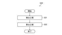
- the rate of change acquisition step (step S20) is a step of acquiring a rate of change, which is the amount of change in fluid pressure per unit time during the determination period after the supply of fluid is stopped in the supply step.
- the determination step (step S30) is a step of determining the state (open state or closed state) of the endoscope conduit 10A based on the change rate acquired in the change rate acquisition step. Each step will be explained below.
- the supply step (step S10) includes, for example, a step of operating the pump with the solenoid valve open to fill the endoscope channel with fluid (step S11), and closing the solenoid valve. (step S12), stopping the pump (step S13), and opening the solenoid valve (step S14).
- step S10 in the state determination device 100 shown in FIG. 5, the solenoid valve 110 is opened, the pump 106 is operated, and the fluid is supplied from the supply conduit 102 into the endoscope conduit 10A, The endoscope conduit 10A is filled with fluid (step S11).
- step S11 based on the control signal from the controller 104, the solenoid valve 110 is opened and the pump 106 is operated.
- a pump 106 supplies fluid to the supply line 102 .
- Supply line 102 supplies fluid to endoscope line 10A via supply port 112.
- the pump 106 By operating the pump 106 with the electromagnetic valve 110 open, the supply conduit 102 and the endoscope conduit 10A are filled with fluid over time.
- FIG. 8 shows the change in pressure in step S11 in period I.
- the pressure of the fluid in the supply conduit 102 increases.
- the pressure of the fluid within supply line 102 is detected by pressure sensor 108 .
- the pressure increases until the supply conduit 102 and the endoscope conduit 10A are filled with fluid. After the endoscope channel 10A is filled with fluid, the pressure becomes constant.
- step S12 the solenoid valve 110 is closed (step S12).
- step S12 the solenoid valve 110 is closed based on a control signal from the controller 104. Solenoid valve 110 remains closed while pump 106 continues to operate, supplying fluid into supply line 102 .
- FIG. 8 shows the change in pressure in step S12 in period II. Since the pump 106 supplies fluid into the supply line 102 with the solenoid valve 110 closed, the pressure within the supply line 102 increases compared to the pressure in step S11 and remains constant, as shown in FIG. pressure.
- step S13 after the pressure in step S12 becomes constant, the pump 106 is stopped based on the control signal from the controller 104. With solenoid valve 110 closed, pump 106 is stopped.
- FIG. 8 shows the change in pressure in step S13 in period III. Since the pump 106 is stopped and the fluid supply is stopped, the pressure within the supply line 102 decreases, as shown in FIG. On the other hand, inside the supply conduit 102, the fluid is kept pressurized at a constant pressure, which is a so-called maintained pressure state. Fluid is stored within the supply pipe line 102 .
- step S14 the solenoid valve 110 is opened (step S14).
- step S14 the solenoid valve 110 is opened based on the control signal from the controller 104.
- pressurized fluid is supplied from the supply conduit 102 to the endoscope conduit 10A via the supply port 112.
- the pressure of the fluid in the supply conduit 102 changes.
- FIG. 8 shows the change in pressure in step S14 in period IV. Since the pump 106 is in a stopped state and the solenoid valve 110 is in an open state, the pressure in the supply line 102 decreases, as shown in FIG.
- the controller 104 determines the state of the endoscope conduit 10A based on the change in pressure (attenuation) during the period when this pressurized fluid is being supplied to the endoscope conduit 10A.
- period IV in FIG. 8 corresponds to a determination period, and during this determination period, the continuous supply of fluid by the pump 106 is stopped. The rate of change in the physical quantity within the supply conduit 102 during this determination period is acquired, and the state of the endoscope conduit 10A is determined based on this rate of change.
- the pressure inside the supply conduit 102 is rapidly reduced as shown in condition 1.
- the pressure is not reduced unless there is a leak elsewhere.
- the pressure will be gradually reduced as in Condition 2 even if the endoscope conduit 10A is in a closed state.
- the change (transition) in the attenuation of the pressure value is different when the endoscope conduit 10A is in the open state (condition 1) and the closed state (condition 2). It is considered possible to determine whether the endoscope channel 10A is open or closed.
- FIG. 9 is an actual graph of pressure values during period IV (judgment period) in FIG. 8.
- the horizontal axis shows time, and the vertical axis shows pressure value.
- pressure values detected by the pressure sensor 108 and corresponding to a plurality of times during the determination period are plotted.
- the graph plots changes (transitions) in pressure values including the open state (condition 1) and the closed state (condition 2). According to the change (transition) of the ideal pressure value shown in FIG. 8, it is possible to determine the open state (condition 1) and the closed state (condition 2).
- the change (transition) of the pressure value shown in FIG. 9 is substantially difficult to determine. If the length of the endoscope conduit 10A, its thickness, or the pressure before the solenoid valve 110 is opened in step S13 vary, this will affect the change (transition) of the attenuation.
- the graph in FIG. 9 plots changes (transitions) in pressure values for dozens of data series with different conditions. In fact, half of the dozens of data series belong to the open state (condition 1), and the remaining half of the data series belong to the closed state (condition 2). For example, when comparing the times at which the pressure reaches P1, there are variations such as t1 and t2 even if they belong to the same closed state (condition 2). Moreover, in the case of t1, there is almost no difference from the open state (condition 1). Therefore, it is difficult to determine whether the endoscope channel 10A is open or closed based on the change (transition) of the pressure value over time.
- the inventors have diligently studied this problem and focused on the rate of change, which is the amount of change in physical quantities per unit time, rather than the change (transition) of physical quantities such as pressure values, and based on the rate of change, The inventors have discovered that it is effective to determine the state (open state or closed state) of the duct 10A, leading to the present invention.
- step S20 the change rate acquisition step (step S20) and the determination step (step S30) will be explained.
- the rate of change acquisition step (step S20) includes, for example, a detection step (step S21) and a calculation step (step S22).
- step S21 physical quantity data indicating the physical quantity of the fluid corresponding to each of a plurality of times within the determination period is detected (step S21).
- step S21 in the state determination device 100, the pressure sensor 108 detects, as physical quantity data, pressure values indicating pressures, which are physical quantities of the fluid, corresponding to a plurality of times within the determination period.
- the pressure value detected by the pressure sensor 108 is acquired by the sensor information acquisition unit 308.
- the sensor information acquisition unit 308 acquires, for example, a pressure value as shown in the graph of FIG. 9 as the pressure within the supply pipe line 102.
- a rate of change (rate of pressure change), which is the amount of change in the pressure value per unit time, is calculated based on the pressure value, which is the physical quantity data detected in the detection step (step S22).
- the pressure change rate calculation unit 318 calculates the pressure change rate based on the pressure value acquired by the sensor information acquisition unit 308 (that is, the pressure value detected by the pressure sensor 108 in step S21).
- the rate of pressure change can also be referred to as the rate of decrease in the pressure value per unit time.
- the pressure change rate calculation unit 318 performs a conversion process to make the change rate constant so that it can be compared with a predetermined threshold (for example, a constant threshold).
- Constantizing the rate of change means making the rate of change approach a predetermined constant, for example, making the slope of the rate of change approach a straight line.
- the conversion process is not limited and includes any process as long as the rate of change can be made constant.
- the conversion process includes, for example, setting an appropriate range so that the rate of change is approximately constant, converting the rate of change into a constant so that it can be compared with a single threshold, and In order to eliminate false detections, this includes excluding ranges that are difficult to stabilize, and performing time-sharing and arithmetic processing to eliminate outliers and variations.
- the rate of change is made constant by logarithmically converting at least one of the physical quantity data and the time data indicating the elapsed time from the start of the determination period.
- FIG. 11 is a semi-logarithmic graph in which the vertical axis is the logarithmic axis of pressure values and the horizontal axis is the time axis.
- the pressure value is plotted on the logarithmic axis for the pressure change (transition) shown in FIG.
- This is a graph in which conversion processing is performed so that the rate of change of physical quantity data is approximately constant.
- logarithmic transformation is shown as the conversion process in FIG. 11, as long as the rate of change can be made constant, the time interval (horizontal axis) may be changed as appropriate, and the interval between physical quantities (vertical axis) may be changed as appropriate. Alternatively, these may be combined and changed as appropriate. That is, the unit intervals of each parameter (time and physical quantity) may be equal intervals, logarithmic intervals, or any predetermined intervals, and can be selected depending on the characteristics of the rate of change.
- the state determination device 100 prepares a constantization pattern of several combinations of time intervals (horizontal axis) and physical quantity intervals (vertical axis) that can constantize the rate of change, and calculates the physical quantity data of the supply pipe 102 during the determination period. When detected, the physical quantity data may be applied to a constantization pattern to constantize the rate of change.
- the flow rate of the supply pipe 102 may be used as the physical quantity data.
- the state determination device 100 in FIG. 5 is provided with a flow rate sensor that detects the flow rate of the fluid flowing through the supply pipe line 102, and the sensor information acquisition unit 308 acquires the detected value of this flow rate sensor.
- the calculation step may include a process of converting the approximately constant rate of change into a constant in order to facilitate comparison with a predetermined threshold (constant).
- FIG. 12 is a graph in which the rates of change of a plurality of data series that are approximately constant as shown in the graph of FIG. 11 are converted so that the slope A of each data series becomes a constant, as will be described later.
- the rate of change can be expressed as a slope A (constant).
- FIG. 12 it can be seen that the slope A is divided into two point sets depending on its magnitude.
- the two point sets are formed by the state (open state and closed state) of the endoscope conduit 10A being reflected in the magnitude of the rate of change (inclination A) of the pressure value of the supply conduit 102. Conversely, if a set of two points can be formed according to the magnitude of the rate of change (inclination A) in the pressure value of the supply conduit 102, the state of the endoscope conduit 10A (open state and closed state) can be determined. .
- FIG. 12 shows a case where the approximately constant rate of change shown in the graph of FIG. 11 is converted into a constant by performing a conversion process. Preferred embodiments are shown below.
- the pressure change rate calculation unit 318 applies the following preferred aspects singly or in combination.
- the rate of change can be calculated for the graph of FIG. 11 based on time-divided data obtained by time-dividing the physical quantity data for each time period.
- the physical quantity data does not need to be continuous in time; as long as it is acquired at intervals long enough to obtain the rate of change, the constant rate of change shown in FIG. 12 can be obtained. .
- the rate of change can be calculated by linearly approximating the time-shared data to the graph of FIG. 11. If linear approximation is possible, the slope A of the rate of change can be obtained as a constant.
- the rate of change can be calculated for the graph of FIG. 11 based on the slope between two points included in the time-sharing data. Since it is a slope between two points, the slope A of the rate of change can be obtained as a constant.
- the rate of change can be calculated by performing linear approximation to the graph of FIG. 11 based on the residual of the time-sharing data. If linear approximation is possible, the slope A of the rate of change can be obtained as a constant.
- the rate of change can be calculated by performing linear approximation to the graph of FIG. 11 such that the sum of squares of the residuals of the time-sharing data is minimized.
- the graph shown in FIG. 12 shows the result of linear approximation to the graph of FIG. 11 in which the sum of squares of the residual errors of the time-sharing data is minimized. It can be understood that the slope A of the rate of change can be obtained as a constant.
- the calculation step may include, for example, (5) an outlier exclusion step of identifying outliers included in the physical quantity data based on the physical quantity data after the conversion process and excluding the outliers from the physical quantity data. preferable.
- the maximum outlier value from the pressure value in the same data series is Preferably, values and minimum values are excluded.
- outliers from the data series when converting from a semilogarithmic graph in which the vertical axis is pressure value and the horizontal axis is time in Figure 11 to the graph with slope A of the rate of change shown in Figure 12, it is possible to correct The slope A of the rate of change can be obtained, and as a result, false detection can be suppressed.
- the calculation step includes (6) a dispersion determination step of determining the degree of dispersion of the physical quantity data based on the physical quantity data after the conversion process has been performed.
- a threshold value is set in advance, and it can be determined whether the physical quantity data is in error based on the threshold value. If it is an error, it is possible to identify the cause and re-measure to prevent false positives.
- the determination period is divided into D1, D2, and D3, and within the range of each divided period D1, D2, and D3, conversions (1) to (6) in the calculation step described above
- conversion processing may be performed such that the slope A of the rate of change of the data series is a constant.
- the determination period is a period after a preset exclusion period has elapsed since the fluid supply was stopped.
- the exclusion period D4 is a certain period after the solenoid valve is opened in step S14.
- the exclusion period D4 is a certain period after the solenoid valve is opened in step S14.
- this fixed period there is a change point in the change (transition) of the pressure value, and the position of the change point varies depending on the model of the endoscope and the opening state of the duct.
- pressure values for this certain period it is possible to exclude ranges in which physical quantity data are difficult to stabilize. Therefore, when performing conversion processing such that the slope A of the pressure change rate of each data series is a constant, the correct slope A can be obtained, and as a result, false detection can be suppressed.
- the determination step (step S30) is a step of determining the state of the endoscope channel, and determines whether the endoscope channel is in an open state or a closed state.
- the determination step (step S30) includes a change rate information acquisition step (step S31) for acquiring the calculated change rate, a comparison step (step S32) for comparing the change rate with a threshold value, and a step in which the endoscope conduit 10A is It includes an open state determining step (step S33) for determining that the endoscope channel 10A is in the open state, and a closed state determining step (step S34) for determining that the endoscope channel 10A is in the closed state.
- the threshold value used in the comparison step is an example of a determination threshold value that indicates opening or occlusion of the endoscopic channel.
- the change rate information acquisition step acquires the change rate calculated in the change rate acquisition step (step S20) (step S31).
- step S31 in the state determining device 100, the endoscope channel state determining unit 320 acquires the rate of change (inclination A) calculated by the rate of pressure change calculating unit 318.
- the comparison step of comparing the rate of change and the threshold value compares the rate of change (slope A) acquired in step S31 with a preset threshold value, and determines whether the rate of change (slope A) satisfies the threshold value (step S32).
- the endoscope channel state determination unit 320 compares the acquired rate of change (inclination A) with a threshold value, and determines whether the threshold value is satisfied.
- the process proceeds to step S33 and determines that the endoscope channel 10A is in an open state.
- step S34 determines that the endoscope channel 10A is in a closed state.
- the result information of the determination process is sent to the control unit 316, for example.
- the control unit 316 stores the result information in the storage unit 314 and displays it on the display operation panel 206 via the input/output I/F.
- the determination process ends as described above.
- FIG. 14 is a diagram for explaining the comparison between the rate of change and the threshold value, and is a diagram in which the threshold value and the state of the endoscope channel are added to FIG. 12. Note that the vertical axis in FIG. 14 indicates the absolute value of the rate of change (inclination A).
- the endoscope duct state determining unit 320 determines the state of the endoscope duct (open state and closed state) by comparing the rate of change (inclination A) with a predetermined threshold value. For example, in the example of FIG. 14, if the rate of change (inclination A) is larger than the threshold value, it is determined that the threshold value is satisfied, and the endoscope channel state determination unit 320 determines that the state of the endoscope channel 10A is in the open state. judge. On the other hand, if the rate of change (inclination A) is smaller than the threshold, the endoscope channel state determining unit 320 determines that the threshold is not satisfied and determines that the state of the endoscope channel 10A is a closed state.
- the time-divided physical quantity data is set as a constant called slope A, and this constant is compared with a predetermined threshold (constant), making it easy to detect abnormal points such as waveform disturbances and outliers. becomes easier. Furthermore, it is also possible to exclude the influence of initial value variations and the like. It is possible to accurately determine the state of the endoscope channel.
- FIG. 14 describes the case where one threshold value is set in advance, the occlusion determination threshold value for determining the occlusion state and the occlusion determination threshold value for determining the open state may be set separately.
- the threshold value in FIG. 14 serves both as a threshold value for determining occlusion and a threshold value for determining opening.
- the physical quantity of the fluid in the present invention is the pressure or flow rate of the fluid, but the physical quantity of the fluid is not limited to this, for example, the physical quantity of the fluid may be the temperature of the fluid.
- a certain aspect (first modification) and an aspect (second modification) in which the physical quantity of the fluid is the flow velocity (kinetic energy) of the fluid may be adopted.
- a temperature sensor (not shown) provided in the supply pipeline 102 detects a temporal change in the temperature of the fluid flowing through the supply pipeline 102, and the temperature change is the amount of change in temperature per unit time.
- the state of patency or occlusion of the endoscopic channel is determined based on the rate.
- the temporal change in the temperature of the fluid detected by the temperature sensor is preferably such that the temperature of the fluid gradually decreases over time, and the rate of temperature change is the rate of decrease in temperature per unit time. Further, when the temperature of the fluid gradually increases over time, the rate of temperature change is the rate of increase in temperature per unit time.
- a flow velocity sensor (not shown) provided in the supply pipeline 102 detects a temporal change in the velocity of the fluid flowing through the supply pipeline 102, and the velocity change is the amount of change in velocity per unit time.
- the state of patency or occlusion of the endoscopic channel is determined based on the rate.
- the temporal change in the fluid velocity detected by the flow velocity sensor is preferably such that the fluid velocity gradually increases over time, and the velocity change rate is the rate of increase in the flow velocity per unit time. Further, when the velocity of the fluid gradually decreases over time, the velocity change rate is the rate of decrease in the flow velocity per unit time.
Abstract
The present invention provides an endoscope conduit condition determination method, an endoscope conduit condition determination device, and an endoscope cleaning/disinfecting device with which it is possible to determine, in a highly accurate manner, whether an endoscope conduit is in an open or closed state. The endoscope conduit condition determination method comprises a feeding step for feeding a compressed fluid to an endoscope conduit, a change rate acquisition step for acquiring the change rate in a physical quantity of the fluid during a determining period after the feeding of the fluid has been stopped, and a determining step for determining whether the endoscope conduit is in an open or closed state on the basis of the change rate acquired in the change rate acquisition step.
Description
本発明は、内視鏡管路の状態判定方法、内視鏡管路の状態判定装置、及び内視鏡洗浄消毒装置に係り、特に、内視鏡の洗浄処理において、内視鏡管路の開通又は閉塞の状態を判定する内視鏡管路の状態判定方法、内視鏡管路の状態判定装置、及び内視鏡洗浄消毒装置に関する。
The present invention relates to a method for determining the state of an endoscope conduit, a device for determining the state of an endoscope conduit, and an endoscope cleaning/disinfecting device. The present invention relates to a method for determining the state of an endoscope conduit, an apparatus for determining the state of an endoscope conduit, and an endoscope cleaning and disinfecting device for determining whether the state is open or blocked.
医療分野で使用される内視鏡は、検査及び治療を目的として、体腔内に挿入されて使用されるものである。そのため、使用後、再度使用するためには洗浄消毒が必要となる。使用済みの内視鏡を洗浄消毒する装置として、内視鏡洗浄消毒装置が知られている。内視鏡洗浄消毒装置は、通常、洗浄、消毒及びすすぎ等の複数の工程を経て洗浄消毒を行う。
Endoscopes used in the medical field are inserted into body cavities for the purpose of examination and treatment. Therefore, after use, it must be cleaned and disinfected before it can be used again. An endoscope cleaning and disinfecting device is known as a device for cleaning and disinfecting used endoscopes. An endoscope cleaning and disinfecting device typically performs cleaning and disinfection through multiple steps such as cleaning, disinfection, and rinsing.
この際、内視鏡の内部に設けられる送気送水管路、吸引管路、処置具挿通管路等の複数の内視鏡内の管路に対しても、洗浄液及び消毒液が供給されることで、洗浄消毒が行われる。その際、内視鏡の管路の閉塞(詰まり)が発生している場合は、洗浄液及び消毒液が管路に供給されにくいため、十分な洗浄及び消毒が行われない。また、洗浄後の内視鏡の操作時に、管路を通して流体等の供給及び吸引が行えなくなる。したがって、内視鏡の管路の開通又は閉塞の状態を判定するための試験が行われる。
At this time, cleaning liquid and disinfectant solution are also supplied to multiple pipes inside the endoscope, such as air and water supply pipes, suction pipes, treatment instrument insertion pipes, etc. This will clean and disinfect. At that time, if the duct of the endoscope is clogged, it is difficult for the cleaning liquid and disinfectant to be supplied to the duct, so that sufficient cleaning and disinfection are not performed. Further, when operating the endoscope after cleaning, it becomes impossible to supply or aspirate fluid through the conduit. Therefore, a test is performed to determine whether the duct of the endoscope is open or blocked.
例えば、下記の特許文献1には、内視鏡の管路内に流体を供給し、管路内を流れる流体の圧力又は流量を測定し、測定値と設定値を比較演算することで、内視鏡の詰まり状況を検出することが記載されている。特許文献2には、内視鏡内のチャンネルに加圧された流体を送り、その背圧をモニターし、背圧が所定値に下がるまでの時間をモニターすることで、チャンネルが接続されて開通しているか、または接続されていないかを判定することが記載されている。
For example, Patent Document 1 below discloses that by supplying fluid into the pipe line of an endoscope, measuring the pressure or flow rate of the fluid flowing inside the pipe line, and calculating the comparison between the measured value and the set value, It is described that the clogging situation of the endoscope is detected. Patent Document 2 discloses that by sending pressurized fluid to a channel in an endoscope, monitoring the back pressure, and monitoring the time until the back pressure drops to a predetermined value, the channel is connected and opened. It describes how to determine whether the connection is connected or not.
また、特許文献3には、内視鏡管路に一連の圧力パルスが印加され、この圧力パルスの最大値及び最小値により、内視鏡管路の開通性を試験することが記載されている。特許文献4には、内視鏡の内部管路内に流体を供給し、流体の圧力又は流量を閾値と比較することで異常を判定することが記載されている。
Further, Patent Document 3 describes that a series of pressure pulses is applied to an endoscope conduit, and the patency of the endoscope conduit is tested based on the maximum and minimum values of the pressure pulses. . Patent Document 4 describes that a fluid is supplied into an internal conduit of an endoscope and an abnormality is determined by comparing the pressure or flow rate of the fluid with a threshold value.
内視鏡の管路の開通又は閉塞の状態を判定する場合は、特許文献1から4に記載されているように、内視鏡の管路内に供給する流体の圧力又は流量の値、あるいは、圧力又は流量が所定の値となる時間により、内視鏡の管路の状態を判定していた。
When determining whether the duct of the endoscope is open or blocked, as described in Patent Documents 1 to 4, the value of the pressure or flow rate of the fluid supplied into the duct of the endoscope, or The state of the duct of the endoscope has been determined based on the time it takes for the pressure or flow rate to reach a predetermined value.
しかしながら、流体の圧力又は流量の測定は、以下の要因により、圧力又は流量の値にばらつきが生じる場合がある。(1)減衰波形には、変化点が存在するが、この変化点の位置は、内視鏡の種類、又は、管路の開通状態で異なる。(2)測定器のばらつき、又は、管路乱流などの影響で減衰中の波形が乱れる。(3)ノイズ等の影響で外れ値が生じる。そのため、流体の圧力又は流量の値にばらつきが生じると誤判定が発生する可能性があった。
However, when measuring the pressure or flow rate of a fluid, variations may occur in the pressure or flow rate values due to the following factors. (1) There is a change point in the attenuation waveform, but the position of this change point differs depending on the type of endoscope or the opening state of the duct. (2) The attenuating waveform is disturbed due to variations in measuring instruments or turbulent flow in the pipeline. (3) Outliers occur due to the influence of noise, etc. Therefore, if variations occur in the values of the pressure or flow rate of the fluid, there is a possibility that an erroneous determination will occur.
本発明はこのような事情に鑑みてなされたものであり、高い精度で、内視鏡管路の開通又は閉塞の状態を判定することができる内視鏡管路の状態判定方法、内視鏡管路の状態判定装置、及び内視鏡洗浄消毒装置を提供することを目的とする。
The present invention has been made in view of the above circumstances, and provides a method for determining the state of an endoscope duct, which can determine whether the endoscope duct is open or blocked with high accuracy, and an endoscope. An object of the present invention is to provide a conduit condition determination device and an endoscope cleaning/disinfecting device.
第1態様の内視鏡管路の状態判定方法は、加圧された流体を内視鏡管路に供給する供給工程と、流体の供給を停止した後の判定期間における流体の物理量の単位時間当たりの変化量である変化率を取得する変化率取得工程と、変化率取得工程で取得した変化率に基づき、内視鏡管路の開通又は閉塞の状態を判定する判定工程と、を備える。
The method for determining the state of an endoscope conduit according to the first aspect includes a supply step of supplying pressurized fluid to an endoscope conduit, and a unit time of the physical quantity of the fluid during a determination period after stopping the supply of the fluid. The present invention includes a change rate acquisition step of acquiring a change rate that is the amount of change per hit, and a determination step of determining whether the endoscopic channel is open or blocked based on the change rate acquired in the change rate acquisition step.
第2態様の内視鏡管路の状態判定方法において、物理量は、流体の圧力又は流量である。
In the method for determining the state of an endoscope conduit according to the second aspect, the physical quantity is the pressure or flow rate of the fluid.
第3態様の内視鏡管路の状態判定方法において、流体の供給の停止は、供給工程により内視鏡管路が流体で満たされた後に行われる。
In the method for determining the state of an endoscope conduit according to the third aspect, the supply of fluid is stopped after the endoscope conduit is filled with fluid in the supply step.
第4態様の内視鏡管路の状態判定方法において、変化率取得工程は、判定期間内の複数の時刻にそれぞれ対応する流体の物理量を示す物理量データを検出する検出工程と、検出工程で検出した物理量データに基づいて変化率を算出する算出工程と、を含む。
In the method for determining the state of an endoscope conduit according to the fourth aspect, the rate of change acquisition step includes a detection step of detecting physical quantity data indicating the physical quantity of the fluid corresponding to each of a plurality of times within the determination period; and a calculation step of calculating a rate of change based on the physical quantity data obtained.
第5態様の内視鏡管路の状態判定方法において、算出工程は、変化率を定数化する変換処理を含む。
In the endoscope channel state determination method of the fifth aspect, the calculation step includes a conversion process that converts the rate of change into a constant.
第6態様の内視鏡管路の状態判定方法において、算出工程は、変換処理として、物理量データと、判定期間の開始からの経過時間を示す時間データと、の少なくともいずれか一方を対数変換することによって、変化率を定数化する。
In the method for determining the state of an endoscope conduit according to the sixth aspect, the calculation step includes, as a conversion process, logarithmically converting at least one of the physical quantity data and the time data indicating the elapsed time from the start of the determination period. By doing this, the rate of change is made constant.
第7態様の内視鏡管路の状態判定方法において、算出工程は、物理量データを時間毎に時分割した時分割データに基づいて変化率を算出する。
In the method for determining the state of an endoscope conduit according to the seventh aspect, the calculation step calculates the rate of change based on time-sharing data obtained by time-sharing the physical quantity data.
第8態様の内視鏡管路の状態判定方法において、算出工程は、時分割データの直線近似を行うことで変化率を算出する。
In the method for determining the state of an endoscope conduit according to the eighth aspect, the calculation step calculates the rate of change by performing linear approximation of the time-shared data.
第9態様の内視鏡管路の状態判定方法において、算出工程は、時分割データに含まれる2点間の傾きに基づいて変化率を算出する。
In the method for determining the state of an endoscope conduit according to the ninth aspect, the calculation step calculates the rate of change based on the slope between two points included in the time-shared data.
第10態様の内視鏡管路の状態判定方法において、算出工程は、時分割データの残差に基づいて直線近似を行うことで変化率を算出する。
In the endoscope channel state determination method of the tenth aspect, the calculation step calculates the rate of change by performing linear approximation based on the residual of the time-sharing data.
第11態様の内視鏡管路の状態判定方法において、算出工程は、時分割データの残差の二乗和が最小となる直線近似を行うことで変化率を算出する。
In the method for determining the state of an endoscope conduit according to the eleventh aspect, the calculation step calculates the rate of change by performing a linear approximation that minimizes the sum of squares of residual errors of the time-shared data.
第12態様の内視鏡管路の状態判定方法において、変換処理が行われた後の物理量データに基づいて物理量データに含まれる外れ値を特定して、物理量データから外れ値を除外する外れ値除外工程を備える。
In the method for determining the state of an endoscope conduit according to the twelfth aspect, an outlier included in the physical quantity data is identified based on the physical quantity data after conversion processing is performed, and the outlier is excluded from the physical quantity data. Includes an exclusion process.
第13態様の内視鏡管路の状態判定方法において、変換処理が行われた後の物理量データに基づいて、物理量データのばらつき度合いを判定するばらつき判定工程を備える。
The method for determining the state of an endoscope conduit according to the thirteenth aspect includes a dispersion determining step of determining the degree of dispersion of the physical quantity data based on the physical quantity data after the conversion process has been performed.
第14態様の内視鏡管路の状態判定方法において、判定工程は、変換処理により定数化された変化率と、内視鏡管路の開通又は閉塞を示す判定閾値とを比較することによって判定を行う。
In the method for determining the state of an endoscope conduit according to the fourteenth aspect, the determination step is performed by comparing the rate of change made constant by the conversion process with a determination threshold value indicating whether the endoscope conduit is open or blocked. I do.
第15態様の内視鏡管路の状態判定方法において、判定期間は、流体の供給を停止してから予め設定された除外期間が経過した後の期間である。
In the method for determining the state of an endoscope conduit according to the fifteenth aspect, the determination period is a period after a preset exclusion period has elapsed after the fluid supply was stopped.
第16態様の内視鏡管路の状態判定装置は、内視鏡管路に接続され、加圧された流体を内視鏡管路に供給する供給管路と、流体の物理量を検出する物理量検出センサと、プロセッサと、を備え、プロセッサは、物理量検出センサで検出した流体の物理量に基づいて、供給された流体の供給を停止した後の判定期間における流体の物理量の単位時間当たりの変化量である変化率を取得し、算出した変化率に基づき、内視鏡管路の状態を判定する。
A state determination device for an endoscope conduit according to a sixteenth aspect includes a supply conduit connected to an endoscope conduit and supplying pressurized fluid to the endoscope conduit, and a physical quantity for detecting a physical quantity of the fluid. The processor includes a detection sensor and a processor, and the processor determines the amount of change in the physical quantity of the fluid per unit time in a determination period after stopping the supply of the supplied fluid, based on the physical quantity of the fluid detected by the physical quantity detection sensor. A rate of change is obtained, and the state of the endoscope channel is determined based on the calculated rate of change.
第17態様の内視鏡管路の状態判定装置において、物理量は、流体の圧力又は流量である。
In the endoscope channel state determination device of the seventeenth aspect, the physical quantity is the pressure or flow rate of the fluid.
第18態様の内視鏡管路の状態判定装置において、流体の供給の停止は、内視鏡管路が流体で満たされた後である。
In the endoscope channel state determination device of the eighteenth aspect, the supply of fluid is stopped after the endoscope channel is filled with fluid.
第19態様の内視鏡管路の状態判定装置において、プロセッサは、判定期間内の複数の時刻にそれぞれ対応する流体の物理量を示す物理量データを検出し、検出した物理量データに基づいて変化率を算出する。
In the endoscope conduit state determination device according to the nineteenth aspect, the processor detects physical quantity data indicating physical quantities of the fluid corresponding to a plurality of times within the determination period, and calculates a rate of change based on the detected physical quantity data. calculate.
第20態様の内視鏡管路の状態判定装置において、プロセッサは、変化率を定数化する変換処理をする。
In the endoscope channel state determination device of the twentieth aspect, the processor performs conversion processing to make the rate of change constant.
第21態様の内視鏡洗浄消毒装置は上述に記載の内視鏡管路の状態判定装置を備える。
The endoscope cleaning and disinfecting device according to the twenty-first aspect includes the endoscope conduit state determination device described above.
本発明によれば、高い精度で、内視鏡管路の開通又は閉塞の状態を判定することができる。
According to the present invention, it is possible to determine the open or closed state of an endoscope channel with high accuracy.
以下、添付図面に従って、本発明に係る内視鏡管路の状態判定方法、内視鏡管路の状態判定装置、及び内視鏡洗浄消毒装置の好ましい実施形態について説明する。
Hereinafter, preferred embodiments of the method for determining the state of an endoscope conduit, the device for determining the state of an endoscope conduit, and the endoscope cleaning and disinfecting device according to the present invention will be described with reference to the accompanying drawings.
図1は、実施形態の内視鏡管路の状態判定方法によって管路の状態が判定される内視鏡10の全体図であり、特に内視鏡10の管路構成を模式的に示している。まず、図1を参照して内視鏡10の構成について簡単に説明する。
FIG. 1 is an overall view of an endoscope 10 in which the state of the conduit is determined by the endoscope conduit state determination method according to the embodiment, and particularly schematically shows the conduit configuration of the endoscope 10. There is. First, the configuration of the endoscope 10 will be briefly described with reference to FIG.
図1に示すように、内視鏡10は、患者の管腔内、例えば胃又は大腸等の消化管内に挿入される挿入部12と、挿入部12に連設される手元操作部14と、を備える。手元操作部14には、ユニバーサルケーブル16が接続され、ユニバーサルケーブル16の先端にはLGコネクタ18が設けられる。LGコネクタ18を光源装置20に接続することにより、照明窓22、22(図2参照)に照明光が伝送される。また、LGコネクタ18は電気コネクタ(不図示)を有しており、この電気コネクタがプロセッサ(不図示)に着脱自在に接続される。なお、LGコネクタ18には、送気送水用の管路24及び吸引用の管路26が接続される。
As shown in FIG. 1, the endoscope 10 includes an insertion section 12 that is inserted into a patient's lumen, for example, into a gastrointestinal tract such as the stomach or large intestine, and a hand operation section 14 that is connected to the insertion section 12. Equipped with A universal cable 16 is connected to the hand operation unit 14, and an LG connector 18 is provided at the tip of the universal cable 16. By connecting the LG connector 18 to the light source device 20, illumination light is transmitted to the illumination windows 22, 22 (see FIG. 2). Further, the LG connector 18 has an electrical connector (not shown), and this electrical connector is detachably connected to a processor (not shown). Note that the LG connector 18 is connected to a conduit 24 for air and water supply and a conduit 26 for suction.
手元操作部14には、送気送水ボタン28、吸引ボタン30及びシャッターボタン32が並設されるとともに、一対のアングルノブ(不図示)及び鉗子挿入口34が設けられている。
The hand operation unit 14 is provided with an air/water supply button 28, a suction button 30, and a shutter button 32 in parallel, as well as a pair of angle knobs (not shown) and a forceps insertion port 34.
図2は、挿入部12の先端側を示した要部斜視図である。図2に示すように、挿入部12は、先端部36、湾曲部38及び軟性部40によって構成され、湾曲部38は、手元操作部14に設けられた上記のアングルノブを回動することによって遠隔的に湾曲操作される。これにより、先端部36の先端面42を所望の方向に向けることができる。
FIG. 2 is a perspective view of the main parts showing the distal end side of the insertion section 12. As shown in FIG. 2, the insertion section 12 includes a distal end section 36, a curved section 38, and a flexible section 40. Curving is controlled remotely. Thereby, the distal end surface 42 of the distal end portion 36 can be directed in a desired direction.
先端部36の先端面42には、観察窓44、照明窓22、22、送気送水ノズル46、及び鉗子口48が設けられる。観察窓44の後方(基端側)には撮像素子(不図示)が配置される。撮像素子は基板(不図示)に支持され、基板には信号ケーブルが接続される。信号ケーブルは図1の挿入部12、手元操作部14、及びユニバーサルケーブル16に挿通されて電気コネクタまで延設され、プロセッサに接続される。したがって、図2の観察窓44から取り込まれた観察像は、撮像素子の受光面に結像されて電気信号に変換され、そして、この電気信号が信号ケーブルを介してプロセッサに出力され、映像信号に変換される。これにより、プロセッサに接続されたモニタ(不図示)に観察画像が表示される。なお、撮像素子としては、CCD(Charge Coupled Device)型のイメージセンサ、又はCMOS(Complementary Metal Oxide Semiconductor)型のイメージセンサが用いられる。
The distal end surface 42 of the distal end portion 36 is provided with an observation window 44, illumination windows 22, 22, an air/water supply nozzle 46, and a forceps port 48. An imaging device (not shown) is arranged behind the observation window 44 (on the proximal end side). The image sensor is supported by a substrate (not shown), and a signal cable is connected to the substrate. The signal cable is inserted through the insertion section 12, the hand-operated section 14, and the universal cable 16 in FIG. 1, and is extended to the electrical connector and connected to the processor. Therefore, the observed image taken in from the observation window 44 in FIG. 2 is focused on the light receiving surface of the image sensor and converted into an electrical signal, and this electrical signal is outputted to the processor via the signal cable to produce a video signal. is converted to As a result, the observed image is displayed on a monitor (not shown) connected to the processor. Note that as the image sensor, a CCD (Charge Coupled Device) type image sensor or a CMOS (Complementary Metal Oxide Semiconductor) type image sensor is used.
照明窓22、22の後方(基端側)にはライトガイド(不図示)の出射端が配設されている。このライトガイドは、図1の挿入部12、手元操作部14、及びユニバーサルケーブル16に挿通される。そして、ライトガイドの入射端がLGコネクタ18のライトガイド棒50に接続される。したがって、LGコネクタ18のライトガイド棒50を光源装置20に接続することによって、光源装置20から照射された照明光がライトガイドを介して照明窓22、22に伝送され、照明窓22、22から照射される。以上が内視鏡10の概略構成である。
An output end of a light guide (not shown) is provided behind (on the proximal end side) of the illumination windows 22, 22. This light guide is inserted into the insertion section 12, the hand operation section 14, and the universal cable 16 in FIG. Then, the incident end of the light guide is connected to the light guide rod 50 of the LG connector 18. Therefore, by connecting the light guide rod 50 of the LG connector 18 to the light source device 20, the illumination light emitted from the light source device 20 is transmitted to the illumination windows 22, 22 via the light guide, and from the illumination windows 22, 22. irradiated. The above is the schematic configuration of the endoscope 10.
次に、内視鏡10の管路構成について説明する。
Next, the duct configuration of the endoscope 10 will be explained.
図1に示すように、内視鏡10の挿入部12には、送気送水管路52が挿通され、この送気送水管路52の先端側の開口に送気送水ノズル46が接続される。送気送水管路52の基端側は、送気管路54と送水管路56とに分岐され、これらの管路の基端側が、手元操作部14に設けられた送気送水用のシリンダ58の内部に連通される。すなわち、送気管路54と送水管路56は、それぞれの一端側がシリンダ58の内部に連通され、且つそれぞれの他端側が1つの管路である送気送水管路52に合流される。
As shown in FIG. 1, an air/water supply conduit 52 is inserted into the insertion portion 12 of the endoscope 10, and an air/water supply nozzle 46 is connected to an opening on the distal end side of the air/water supply conduit 52. . The base end side of the air and water supply pipe 52 is branched into an air supply pipe 54 and a water supply pipe 56, and the base end side of these pipes is connected to a cylinder 58 for air and water supply provided in the hand operation unit 14. communicated with the inside of the That is, one end of each of the air supply pipe 54 and the water supply pipe 56 is communicated with the interior of the cylinder 58, and the other end of each is joined to the air and water supply pipe 52, which is one pipe.
また、シリンダ58の内部には、給気管路60と給水管路62のそれぞれの先端側が連通されるとともに、送気送水ボタン28が着脱自在に取り付けられる。送気送水ボタン28が突出した状態では送気管路54と給気管路60とがシリンダ58を介して連通され、送気送水ボタン28を押下操作することによって、送水管路56と給水管路62とがシリンダ58を介して連通される。送気送水ボタン28には通気孔(不図示)が形成されており、この通気孔を介して給気管路60が外気に連通されている。
Further, inside the cylinder 58, the respective distal ends of the air supply pipe line 60 and the water supply pipe line 62 are communicated with each other, and the air/water supply button 28 is detachably attached. When the air/water supply button 28 is protruded, the air supply pipe 54 and the air supply pipe 60 are communicated via the cylinder 58, and by pressing the air/water supply button 28, the water supply pipe 56 and the water supply pipe 62 are communicated with each other via the cylinder 58. are communicated via the cylinder 58. A ventilation hole (not shown) is formed in the air/water supply button 28, and the air supply pipe line 60 is communicated with the outside air through the ventilation hole.
給気管路60と給水管路62は、ユニバーサルケーブル16に挿通され、LGコネクタ18の送水コネクタ64に向けて延設される。送水コネクタ64には、管路24が着脱自在に接続され、管路24の先端が貯水タンク66に連結される。そして、給水管路62が貯水タンク66の液面下に連通され、給気管路60が液面上に連通される。
The air supply pipe line 60 and the water supply pipe line 62 are inserted into the universal cable 16 and extend toward the water supply connector 64 of the LG connector 18. A conduit 24 is detachably connected to the water supply connector 64 , and the tip of the conduit 24 is connected to a water storage tank 66 . The water supply pipe 62 is communicated below the liquid level of the water storage tank 66, and the air supply pipe 60 is communicated above the liquid level.
送水コネクタ64には、エア管路68が接続されており、このエア管路68は、給気管路60に連通されている。また、エア管路68は、LGコネクタ18を光源装置20に接続することによって、光源装置20内のエアポンプ70に連通される。したがって、エアポンプ70を駆動してエアを送気すると、エア管路68を介して給気管路60にエアが送気される。このエアは、送気送水ボタン28の非操作時には、送気送水ボタン28の通気孔(不図示)を介して外気に放出されるが、術者が通気孔を塞ぐことによって、給気管路60のエアが送気管路54に送気され、送気送水ノズル46からエアが噴射される。また、送気送水ボタン28を押下操作すると、給気管路60と送気管路54が遮断されるため、エア管路68に給気されたエアは、貯水タンク66の液面上に供給される。これにより、貯水タンク66の内圧が高まって給水管路62に水が送液される。そして、送水管路56を介して送気送水ノズル46から水が噴射される。このように送気送水ノズル46からエア又は水が噴射され、これらが観察窓44に吹き付けられることによって観察窓44が洗浄される。
An air conduit 68 is connected to the water supply connector 64, and this air conduit 68 communicates with the air supply conduit 60. Furthermore, the air pipe line 68 is communicated with an air pump 70 in the light source device 20 by connecting the LG connector 18 to the light source device 20 . Therefore, when the air pump 70 is driven to supply air, the air is supplied to the air supply pipe 60 via the air pipe 68. When the air and water supply button 28 is not operated, this air is released to the outside air through a vent hole (not shown) of the air and water supply button 28, but when the operator closes the vent hole, the air supply pipe 60 The air is supplied to the air supply pipe line 54, and the air is injected from the air and water supply nozzle 46. Furthermore, when the air and water supply button 28 is pressed, the air supply line 60 and the air supply line 54 are cut off, so that the air supplied to the air line 68 is supplied above the liquid level of the water storage tank 66. . As a result, the internal pressure of the water storage tank 66 increases and water is sent to the water supply pipe 62. Then, water is injected from the air/water supply nozzle 46 via the water supply pipe line 56. In this way, air or water is injected from the air/water supply nozzle 46 and is blown onto the observation window 44, thereby cleaning the observation window 44.
図1に示すように、内視鏡10の挿入部12には、鉗子管路72が挿通され、この鉗子管路72の先端側に鉗子口48が開口される、鉗子管路72の基端側は、2本の管路72A及び72Bに分岐され、一方の管路72Aの基端側が鉗子挿入口34に連通され、他方の管路72Bの基端側が吸引用のシリンダ74の内部に連通される。したがって、鉗子挿入口34から鉗子等の処置具を挿入した場合には、鉗子口48から処置具を導出することができる。
As shown in FIG. 1, a forceps channel 72 is inserted into the insertion section 12 of the endoscope 10, and a forceps port 48 is opened at the distal end side of the forceps channel 72. The side is branched into two pipe lines 72A and 72B, the proximal end side of one pipe line 72A is communicated with the forceps insertion port 34, and the proximal end side of the other pipe line 72B is communicated with the inside of the cylinder 74 for suction. be done. Therefore, when a treatment tool such as forceps is inserted through the forceps insertion port 34, the treatment tool can be taken out from the forceps port 48.
シリンダ74の内部には、吸引管路76の基端側が連通されるとともに、吸引ボタン30が取り付けられる。吸引ボタン30が突出した状態では、吸引管路76が外気に連通され、吸引ボタン30を押下操作することによって、吸引管路76と鉗子管路72とがシリンダ74及び管路72Bを介して連通される。
Inside the cylinder 74, the proximal end side of the suction conduit 76 is communicated, and the suction button 30 is attached. When the suction button 30 is protruded, the suction line 76 is communicated with the outside air, and by pressing down the suction button 30, the suction line 76 and the forceps line 72 are communicated via the cylinder 74 and the line 72B. be done.
吸引管路76は、LGコネクタ18の吸引コネクタ78まで延設されており、この吸引コネクタ78に管路26を接続することによって、不図示の吸引装置に連通される。したがって、吸引装置を駆動した状態で吸引ボタン30を押下操作することによって、鉗子口48から病変部等を、鉗子管路72を介して吸引することができる。
The suction line 76 extends to a suction connector 78 of the LG connector 18, and by connecting the line 26 to this suction connector 78, it communicates with a suction device (not shown). Therefore, by pressing down the suction button 30 while the suction device is driven, the lesion or the like can be suctioned from the forceps port 48 through the forceps conduit 72.
既述したように、内視鏡10は、送気送水系を構成する複数の送気送水系管路(給気管路60、給水管路62、シリンダ58、送気管路54、送水管路56及び送気送水管路52)を備える。複数の送気送水系管路は洗浄の対象となり、複数の送気送水系管路を洗浄するため、弁体を含む送気送水ボタン28が、シリンダ58から取り外し可能となっている。同様に、吸引系を構成する複数の吸引系管路(吸引管路76、シリンダ74、管路72B、管路72A及び鉗子管路72)を備える。複数の吸引系管路は洗浄の対象となり、複数の吸引系管路を洗浄するため、弁体を含む吸引ボタン30もシリンダ74から取り外し可能となっている。
As described above, the endoscope 10 includes a plurality of air and water supply system pipes (air supply pipe 60, water supply pipe 62, cylinder 58, air supply pipe 54, water supply pipe 56) that constitute the air and water supply system. and an air/water supply pipe 52). The plurality of air and water supply system pipes are to be cleaned, and in order to clean the plurality of air and water supply system pipes, the air and water supply button 28 including the valve body is removable from the cylinder 58. Similarly, a plurality of suction system conduits (suction conduit 76, cylinder 74, conduit 72B, conduit 72A, and forceps conduit 72) constituting the suction system are provided. The plurality of suction system conduits are to be cleaned, and in order to clean the plurality of suction system conduits, the suction button 30 including the valve body is also removable from the cylinder 74.
次に、図4を参照して実施形態の内視鏡洗浄消毒装置(以下、洗浄装置と言う。)200について説明する。図4は、洗浄装置200の概略構成を示すブロック図である。図4では、内視鏡管路の洗浄及び内視鏡管路の状態の判定に関連する構成を示し、洗浄装置200の詳細な構成は説明を省略する。洗浄装置200は、内視鏡10の送気送水系管路、吸引系管路及びその他管路(これらを合わせて内視鏡管路を称する場合がある。)を消毒、洗浄及び内視鏡管路の状態の判定を行うことができる。
Next, an endoscope cleaning and disinfecting device (hereinafter referred to as cleaning device) 200 of the embodiment will be described with reference to FIG. FIG. 4 is a block diagram showing a schematic configuration of the cleaning device 200. FIG. 4 shows a configuration related to cleaning the endoscope channel and determining the state of the endoscope channel, and the detailed configuration of the cleaning device 200 will not be described. The cleaning device 200 disinfects and cleans the air and water supply system conduit, the suction system conduit, and other conduits (these may be collectively referred to as an endoscope conduit) of the endoscope 10, and cleans the endoscope 10. The state of the pipeline can be determined.
図4に示すように、洗浄装置200は、箱型の装置本体202と、装置本体202の上部に設けられた洗浄槽204及び表示操作パネル206と、を備える。洗浄槽204は上部が開放された水槽であり、使用後の内視鏡10を収容する。洗浄槽204は例えばステンレス等の耐熱性及び耐蝕性等に優れた金属で形成され、洗浄液又は消毒液等の液体を貯留できる。
As shown in FIG. 4, the cleaning device 200 includes a box-shaped device main body 202, a cleaning tank 204 and a display operation panel 206 provided at the top of the device main body 202. The cleaning tank 204 is a water tank with an open top, and accommodates the endoscope 10 after use. The cleaning tank 204 is made of a metal with excellent heat resistance and corrosion resistance, such as stainless steel, and can store a liquid such as a cleaning solution or a disinfectant solution.
表示操作パネル206は、内視鏡10の洗浄、消毒及び状態の判定に関する各種設定や、洗浄及び消毒の開始または停止等を指示するための多数のボタンを備える。また、表示操作パネル206は、例えば液晶ディスプレイを備え、各種設定画面、各工程の残り時間又はトラブル発生時の警告メッセージ等を表示する。表示操作パネル206は表示パネルと操作パネルとに分離されていてもよい。
The display operation panel 206 includes a large number of buttons for various settings related to cleaning, disinfection, and status determination of the endoscope 10, and for instructing to start or stop cleaning and disinfection. Further, the display operation panel 206 includes, for example, a liquid crystal display, and displays various setting screens, the remaining time of each process, a warning message when a trouble occurs, and the like. The display operation panel 206 may be separated into a display panel and an operation panel.
表示操作パネル206は、コントローラ208と接続される。コントローラ208は表示操作パネル206から指示を受付け、指示に従って洗浄装置200の全体を制御する。また、コントローラ208は表示操作パネル206を制御し、各種情報を表示させる。
The display operation panel 206 is connected to the controller 208. Controller 208 receives instructions from display operation panel 206 and controls the entire cleaning apparatus 200 according to the instructions. Further, the controller 208 controls the display operation panel 206 to display various information.
洗浄装置200は、液体貯留タンク210と、液体貯留タンク210に一端の側が接続された液体供給路212と、液体供給路212に配置されたポンプ214及び電磁弁216と、を備える。液体貯留タンク210は、洗浄液、消毒液又はアルコール等の液体218を貯留する。ポンプ214は液体貯留タンク210から液体218を吸引し、液体供給路212に液体218を供給する。電磁弁216の開状態と閉状態とを切り換えることで、液体供給路212への液体218の供給と停止とが切り換えられる。
The cleaning device 200 includes a liquid storage tank 210, a liquid supply path 212 whose one end side is connected to the liquid storage tank 210, and a pump 214 and a solenoid valve 216 arranged in the liquid supply path 212. The liquid storage tank 210 stores a liquid 218 such as cleaning liquid, disinfectant liquid, or alcohol. Pump 214 sucks liquid 218 from liquid storage tank 210 and supplies liquid 218 to liquid supply path 212 . By switching the electromagnetic valve 216 between an open state and a closed state, supply and stop of the liquid 218 to the liquid supply path 212 are switched.
洗浄装置200は、エアポンプ220と、エアポンプ220に一端の側が接続されたエア供給路222と、エア供給路222に配置されたフィルタ224及び電磁弁226と、を備える。エアポンプ220はエア供給路222に気体としてエアを供給する。フィルタ224は、エアポンプ220の下流側で且つ電磁弁226の上流側に配置され、エア中の雑菌を補足してエアを浄化する。電磁弁226の開状態と閉状態とを切り換えることで、エア供給路222へのエアの供給と停止とが切り換えられる。
The cleaning device 200 includes an air pump 220, an air supply path 222 whose one end is connected to the air pump 220, and a filter 224 and a solenoid valve 226 arranged in the air supply path 222. The air pump 220 supplies air as a gas to the air supply path 222. The filter 224 is disposed downstream of the air pump 220 and upstream of the solenoid valve 226, and purifies the air by capturing bacteria in the air. By switching the electromagnetic valve 226 between an open state and a closed state, supply and stop of air to the air supply path 222 can be switched.
洗浄装置200は、主管路230と、主管路230に配置された逆止弁232及び圧力センサ234と、を備える。逆止弁232は主管路230における流体(液体及び気体)の逆流を防止する。圧力センサ234は主管路230に供給された流体の物理量の一つである圧力の圧力値を検出する。圧力センサ234は、逆止弁232の下流側に配置される。
The cleaning device 200 includes a main pipe 230, a check valve 232 and a pressure sensor 234 arranged in the main pipe 230. The check valve 232 prevents backflow of fluid (liquid and gas) in the main conduit 230. The pressure sensor 234 detects the pressure value, which is one of the physical quantities of the fluid supplied to the main pipe 230. Pressure sensor 234 is arranged downstream of check valve 232 .
洗浄装置200は、分岐管路241、242、243、244及び245と、供給ポート251、252、253、254及び255と、循環路246と、を備える。分岐管路241、242、243、244及び245は、それぞれの一端の側で主管路230と接続される。供給ポート251、252、253、254及び255は、分岐管路241、242、243、244及び245のそれぞれの他端の側に接続される。供給ポート251、252、253、254及び255は洗浄槽204に配置される。分岐管路241、242、243、244及び245には、電磁弁261、262、263、264及び265がそれぞれ配置される。電磁弁261、262、263、264及び265の開状態と閉状態とを切り換えることで、分岐管路241、242、243、244及び245のそれぞれへの流体の供給と停止とが切り換えられる。
The cleaning device 200 includes branch pipes 241, 242, 243, 244, and 245, supply ports 251, 252, 253, 254, and 255, and a circulation path 246. Branch pipes 241, 242, 243, 244 and 245 are connected to main pipe 230 at one end of each. Supply ports 251, 252, 253, 254 and 255 are connected to the other end sides of branch lines 241, 242, 243, 244 and 245, respectively. Supply ports 251 , 252 , 253 , 254 and 255 are arranged in cleaning tank 204 . Solenoid valves 261, 262, 263, 264 and 265 are arranged in branch pipes 241, 242, 243, 244 and 245, respectively. By switching the electromagnetic valves 261, 262, 263, 264, and 265 between open and closed states, supply and stop of fluid to each of the branch pipes 241, 242, 243, 244, and 245 can be switched.
分岐管路243には、逆止弁271と圧力センサ272とが配置される。逆止弁271は電磁弁263の上流側に配置され、圧力センサ272は電磁弁263の下流側に配置される。逆止弁271は分岐管路243における流体の逆流を防止する。圧力センサ272は分岐管路243に供給された流体の物理量の一つである圧力の圧力値を検出する。
A check valve 271 and a pressure sensor 272 are arranged in the branch pipe 243. The check valve 271 is arranged upstream of the electromagnetic valve 263, and the pressure sensor 272 is arranged downstream of the electromagnetic valve 263. The check valve 271 prevents backflow of fluid in the branch line 243 . The pressure sensor 272 detects the pressure value, which is one of the physical quantities of the fluid supplied to the branch pipe line 243.
図3に示される内視鏡10は、図1に示される内視鏡10と同様に複数の管路を備えている。なお、図3に示される内視鏡10は、吸引系管路及び送気送水系管路以外に副送水系管路を備えている。
The endoscope 10 shown in FIG. 3 includes a plurality of ducts similarly to the endoscope 10 shown in FIG. 1. Note that the endoscope 10 shown in FIG. 3 includes a sub-water supply system conduit in addition to the suction system conduit and the air/water supply system conduit.
供給ポート251、252、253、254及び255には、それぞれチューブ281、282、283、284及び285が接続される。供給ポート251はチューブ281を介して内視鏡10の吸引系管路に接続される。供給ポート252はチューブ282を介して内視鏡10の送気送水系管路に接続される。供給ポート253はチューブ283を介して内視鏡10の送気送水系管路に接続される。供給ポート254はチューブ284を介して内視鏡10の副送水系管路に接続される。供給ポート255はチューブ285を介して内視鏡10の吸引系管路に接続される。
Tubes 281, 282, 283, 284 and 285 are connected to the supply ports 251, 252, 253, 254 and 255, respectively. The supply port 251 is connected to the suction system conduit of the endoscope 10 via a tube 281. The supply port 252 is connected to the air and water supply system conduit of the endoscope 10 via a tube 282. The supply port 253 is connected to the air and water supply system conduit of the endoscope 10 via a tube 283. The supply port 254 is connected to the sub-water supply line of the endoscope 10 via a tube 284. The supply port 255 is connected to the suction system line of the endoscope 10 via a tube 285.
洗浄装置200における供給管路は、流体の供給源から供給ポートまでの管路と見做すことができる。例えば、流体が液体の場合、液体貯留タンク210と供給ポート251とを接続する液体供給路212と主管路230と分岐管路241とが供給管路を構成する。また、流体が気体の場合、エアポンプ220と供給ポート251とを接続するエア供給路222と主管路230と分岐管路241とが供給管路を構成する。
The supply pipeline in the cleaning device 200 can be regarded as a pipeline from the fluid supply source to the supply port. For example, when the fluid is a liquid, the liquid supply line 212, the main line 230, and the branch line 241 that connect the liquid storage tank 210 and the supply port 251 constitute a supply line. Furthermore, when the fluid is gas, the air supply line 222 connecting the air pump 220 and the supply port 251, the main line 230, and the branch line 241 constitute a supply line.
他の供給ポート252、253、254及び255も、供給ポート251と同様に、流体の供給源から供給ポートとまでの管路を洗浄装置200における供給管路と見做すことができる。
Similarly to the supply port 251, the other supply ports 252, 253, 254, and 255 can also be regarded as the supply pipeline in the cleaning device 200, as the pipeline from the fluid supply source to the supply port.
既述したように、吸引系管路、送気送水系管路及び副送水系管路がそれぞれ内視鏡10の内視鏡管路を構成する。
As described above, the suction system conduit, the air/water supply system conduit, and the sub-water supply system conduit each constitute an endoscope conduit of the endoscope 10.
循環路246は、その一端の側で、主管路230に接続される。循環路246は、主管路230において、分岐管路241、242、243、244及び245が接続される側と反対の側で接続される。循環路246は、他端の側に循環ポート256が接続される。循環路246にはポンプ273が配置される。ポンプ273は循環ポート256から洗浄槽204の液体を吸引し、主管路230に供給する。
The circulation path 246 is connected to the main pipe 230 at one end thereof. The circulation path 246 is connected to the main pipe 230 on the side opposite to the side to which the branch pipes 241, 242, 243, 244, and 245 are connected. A circulation port 256 is connected to the other end of the circulation path 246 . A pump 273 is arranged in the circulation path 246. Pump 273 sucks the liquid from cleaning tank 204 through circulation port 256 and supplies it to main pipe 230 .
電磁弁216、226、261、262、263、264及び265はコントローラ208に接続され、コントローラ208がそれぞれの電磁弁216、226、261、262、263、264及び265の開状態と閉状態とを切り換える。
The solenoid valves 216, 226, 261, 262, 263, 264, and 265 are connected to the controller 208, and the controller 208 controls the open and closed states of each solenoid valve 216, 226, 261, 262, 263, 264, and 265. Switch.
また、ポンプ214、273及びエアポンプ220はコントローラ208に接続され、コントローラ208が、ポンプ214、273及びエアポンプ220の駆動を制御する。
Further, the pumps 214, 273 and the air pump 220 are connected to the controller 208, and the controller 208 controls the driving of the pumps 214, 273 and the air pump 220.
圧力センサ234及び272はコントローラ208に接続され、コントローラ208は圧力センサ234及び272が検出した流体の圧力値を取得できるよう構成されている。圧力センサ234及び272は物理量検出センサの一例である。
The pressure sensors 234 and 272 are connected to the controller 208, and the controller 208 is configured to be able to obtain the pressure values of the fluid detected by the pressure sensors 234 and 272. The pressure sensors 234 and 272 are examples of physical quantity detection sensors.
なお、コントローラ208は、各種のプロセッサ(Processor)及びメモリ等から構成された演算回路を備える。各種のプロセッサには、CPU(Central Processing Unit)、GPU(Graphics Processing Unit)、ASIC(Application Specific Integrated Circuit)、及びプログラマブル論理デバイス[例えばSPLD(Simple Programmable Logic Devices)、CPLD(Complex Programmable Logic Device)、及びFPGA(Field Programmable Gate Arrays)]等が含まれる。なお、コントローラ208の各種機能は、1つのプロセッサにより実現されてもよいし、同種または異種の複数のプロセッサで実現されてもよい。
Note that the controller 208 includes an arithmetic circuit made up of various processors, memories, and the like. Various types of processors include CPUs (Central Processing Unit), GPUs (Graphics Processing Unit), ASICs (Application Specific Integrated Circuits), and programmable logic devices [such as SPLDs (Simple Programmable Logic Devices), CPLDs (Complex Programmable Logic Devices), and FPGA (Field Programmable Gate Arrays). Note that the various functions of the controller 208 may be realized by one processor, or may be realized by multiple processors of the same type or different types.
次に、コントローラ208の概略構成について説明する。図4は、洗浄装置200のコントローラ(制御装置と称する)208の概略構成を示すブロック図である。制御装置208には、表示操作パネル206、圧力センサ300、電磁弁302、及びポンプ304が接続されている。圧力センサ300は、例えば、洗浄装置200に配置される圧力センサ234及び272(図3参照)に相当する。電磁弁302は洗浄装置200に配置される電磁弁216、226、261、262、263、264及び265に相当する。ポンプ304は、洗浄装置200に配置されるポンプ214、273及びエアポンプ220に相当する。
Next, the schematic configuration of the controller 208 will be explained. FIG. 4 is a block diagram showing a schematic configuration of a controller (referred to as a control device) 208 of the cleaning device 200. A display operation panel 206, a pressure sensor 300, a solenoid valve 302, and a pump 304 are connected to the control device 208. The pressure sensor 300 corresponds to, for example, the pressure sensors 234 and 272 (see FIG. 3) arranged in the cleaning device 200. The solenoid valve 302 corresponds to the solenoid valves 216, 226, 261, 262, 263, 264, and 265 arranged in the cleaning device 200. Pump 304 corresponds to pumps 214 and 273 and air pump 220 arranged in cleaning device 200.
制御装置208は、主として、入出力I/F(インターフェイス)306、センサ情報取得部308、電磁弁制御部310、ポンプ制御部312、記憶部314、制御部316、圧力変化率算出部318及び内視鏡管路状態判定部320を備え、記憶部314から読み出した不図示の制御プログラムを実行することで、それぞれの機能を実現し、処理を実行する。制御部316は制御装置208の全体の処理を制御する。
The control device 208 mainly includes an input/output I/F (interface) 306, a sensor information acquisition section 308, a solenoid valve control section 310, a pump control section 312, a storage section 314, a control section 316, a pressure change rate calculation section 318, and an internal The endoscope duct state determining unit 320 is provided, and by executing a control program (not shown) read from the storage unit 314, each function is realized and processing is executed. The control unit 316 controls the overall processing of the control device 208.
入出力インターフェイス306は、表示操作パネル206を介して洗浄装置200に様々なデータ(情報)を入力でき、また洗浄装置200から様々なデータ(情報)を出力できる。また、入出力インターフェイス306は、表示操作パネル206以外のネットワーク、または他のデバイスなどと有線及び無線通信を介してデータの入出力を行うことができる。
The input/output interface 306 can input various data (information) to the cleaning device 200 via the display operation panel 206, and can output various data (information) from the cleaning device 200. Further, the input/output interface 306 can input/output data to/from a network other than the display operation panel 206 or other devices via wired or wireless communication.
センサ情報取得部308は、圧力センサ300が検出した圧力値を取得する。センサ情報取得部308は、圧力センサ300が検出する圧力値以外の物理量、例えば、流量センサを備える場合は流量値を取得できるよう構成される。すなわち、センサ情報取得部308は、取得する物理量に相応する構成とされる。
The sensor information acquisition unit 308 acquires the pressure value detected by the pressure sensor 300. The sensor information acquisition unit 308 is configured to be able to acquire a physical quantity other than the pressure value detected by the pressure sensor 300, for example, a flow rate value when a flow rate sensor is provided. That is, the sensor information acquisition unit 308 has a configuration corresponding to the physical quantity to be acquired.
電磁弁制御部310は、制御部316からの制御信号に基づき、電磁弁302の開状態と閉状態とを切り換える。ポンプ制御部312は、制御部316からの制御信号に基づき、ポンプ304の回転数などを制御し、流体の供給量を制御する。
The solenoid valve control unit 310 switches the solenoid valve 302 between an open state and a closed state based on a control signal from the control unit 316. The pump control unit 312 controls the rotation speed of the pump 304 and the like, based on the control signal from the control unit 316, and controls the amount of fluid supplied.
記憶部314は、洗浄装置200全体の制御に用いられる制御プログラムの他、内視鏡管路の状態判定に用いられる制御プログラム、各種制御情報、過去の使用状況などを記憶する。
The storage unit 314 stores a control program used to control the entire cleaning device 200, a control program used to determine the state of the endoscope channel, various control information, past usage conditions, and the like.
圧力変化率算出部318は、圧力センサ300が検出しセンサ情報取得部308により取得された圧力値に基づいて、後述するように、圧力の変化率を算出する。
The pressure change rate calculation unit 318 calculates the rate of pressure change, as described later, based on the pressure value detected by the pressure sensor 300 and acquired by the sensor information acquisition unit 308.
内視鏡管路状態判定部320は、圧力変化率算出部318で算出した変化率に基づいて、後述するように、内視鏡管路の状態を判定する。
The endoscope channel state determination unit 320 determines the state of the endoscope channel based on the rate of change calculated by the pressure change rate calculation unit 318, as described below.
次に、実施形態の状態判定装置100について説明する。なお、状態判定装置100は、洗浄装置200に含まれるもの(洗浄装置200の構成要素によって実現されるもの)であり、以下では、内視鏡管路の状態判定を行うために必要な構成要素を備えたものを状態判定装置と称する。図5は状態判定装置100と内視鏡10の内視鏡管路10Aとの接続構成を示す。状態判定装置100は、流体が供給される供給管路102と、コントローラ104と、流体を供給するポンプ106と、流体の圧力を検出する圧力センサ108と、開状態と閉状態とを切り換えることで流体の供給と停止とを切り換える電磁弁110と、供給ポート112と、逆止弁114と、を備える。状態判定装置100の供給管路102と内視鏡10の内視鏡管路10Aとが供給ポート112を介して接続される。供給管路102と内視鏡管路10Aとは供給ポート112に加えてチューブを介して接続されてもよい。
Next, the state determination device 100 of the embodiment will be described. Note that the state determination device 100 is included in the cleaning device 200 (realized by the components of the cleaning device 200), and the components necessary for determining the state of the endoscope channel will be described below. A device equipped with this is called a state determination device. FIG. 5 shows a connection configuration between the state determination device 100 and the endoscope channel 10A of the endoscope 10. The state determination device 100 switches between an open state and a closed state, a supply pipe line 102 to which fluid is supplied, a controller 104, a pump 106 that supplies fluid, and a pressure sensor 108 that detects the pressure of the fluid. It includes an electromagnetic valve 110 that switches between supplying and stopping fluid, a supply port 112, and a check valve 114. The supply conduit 102 of the state determining device 100 and the endoscope conduit 10A of the endoscope 10 are connected via a supply port 112. The supply conduit 102 and the endoscope conduit 10A may be connected via a tube in addition to the supply port 112.
供給管路102は図3で説明した供給管路に相当し、コントローラ104は図4で説明したコントローラ208に相当し、ポンプ106は図4で説明したポンプ304に相当し、圧力センサ108は図4で説明した圧力センサ300に相当し、電磁弁110は図4で説明した電磁弁302し、逆止弁114は図3で説明した逆止弁232、271に相当し、供給ポート112は図3で説明した供給ポート251~255に相当する。内視鏡管路10Aは図3で説明した吸引系管路、送気送水系管路及び副送水系管路に相当する。
The supply line 102 corresponds to the supply line explained in FIG. 3, the controller 104 corresponds to the controller 208 explained in FIG. 4, the pump 106 corresponds to the pump 304 explained in FIG. 4, the solenoid valve 110 corresponds to the solenoid valve 302 described in FIG. 4, the check valve 114 corresponds to the check valves 232 and 271 described in FIG. This corresponds to the supply ports 251 to 255 described in 3. The endoscope conduit 10A corresponds to the suction system conduit, the air/water supply system conduit, and the sub-water supply system conduit explained in FIG.
次に内視鏡管路の状態判定方法について説明する。内視鏡10の洗浄は、例えば、供給管路102と内視鏡管路10Aとを供給ポート112を介して接続し、電磁弁110を開状態でポンプ106を駆動し、流体を供給管路102に供給し、供給ポート112から内視鏡管路10Aに流体を供給することで実施される。内視鏡10の洗浄は、例えば、洗浄工程、消毒工程、及びすすぎ工程により実施され、洗浄液、消毒液、又は水等の流体が、内視鏡管路10Aに所定の量が流れることによって、内視鏡管路10A内の洗浄が行われる。一方で、内視鏡管路10Aに所定の量が流れない、すなわち、内視鏡管路10Aが閉塞している場合は、十分な洗浄が行われないのみでなく、使用時に流体の供給、又は、吸引を行えないことになる。したがって、内視鏡10の洗浄を行う前に、内視鏡管路10Aの状態判定を行うことが重要となる。
Next, a method for determining the state of the endoscope channel will be explained. To clean the endoscope 10, for example, the supply conduit 102 and the endoscope conduit 10A are connected via the supply port 112, the solenoid valve 110 is opened, the pump 106 is driven, and the fluid is supplied to the supply conduit. 102 and by supplying fluid from the supply port 112 to the endoscope conduit 10A. The cleaning of the endoscope 10 is performed, for example, by a cleaning process, a disinfection process, and a rinsing process, and a predetermined amount of fluid such as a cleaning liquid, a disinfectant liquid, or water flows through the endoscope conduit 10A. The inside of the endoscope channel 10A is cleaned. On the other hand, if the predetermined amount does not flow into the endoscope conduit 10A, that is, if the endoscope conduit 10A is blocked, not only will sufficient cleaning not be performed, but the fluid supply will be interrupted during use. Or, suction cannot be performed. Therefore, before cleaning the endoscope 10, it is important to determine the state of the endoscope channel 10A.
図6は、内視鏡管路の状態判定方法のフローチャートである。図7は供給工程のフローチャートである。図8は、図7に示す供給工程における、供給管路内の圧力の変化を示すグラフである。図9は、図8の判定期間に対する実際の圧力値のグラフである。図10は、変化率取得工程のフローチャートである。図11は、判定工程のフローチャートである。
FIG. 6 is a flowchart of a method for determining the state of an endoscope channel. FIG. 7 is a flowchart of the supply process. FIG. 8 is a graph showing changes in pressure within the supply pipe line during the supply process shown in FIG. FIG. 9 is a graph of actual pressure values versus the determination period of FIG. FIG. 10 is a flowchart of the change rate acquisition process. FIG. 11 is a flowchart of the determination process.
内視鏡管路の状態判定方法は、図6に示すように、供給工程(ステップS10)と、変化率取得工程(ステップS20)と、判定工程(ステップS30)と、を含む。供給工程(ステップS10)は、加圧された流体を内視鏡管路10Aに供給する工程である。変化率取得工程(ステップS20)は、供給工程において、流体の供給を停止した後の判定期間における流体の圧力の単位時間の変化量である変化率を取得する工程である。判定工程(ステップS30)は、変化率取得工程で取得した変化率に基づいて、内視鏡管路10Aの状態(開通状態と閉塞状態)を判定する工程である。以下、各工程について説明する。
As shown in FIG. 6, the method for determining the state of the endoscope channel includes a supply step (step S10), a rate of change acquisition step (step S20), and a determination step (step S30). The supply step (step S10) is a step of supplying pressurized fluid to the endoscope conduit 10A. The rate of change acquisition step (step S20) is a step of acquiring a rate of change, which is the amount of change in fluid pressure per unit time during the determination period after the supply of fluid is stopped in the supply step. The determination step (step S30) is a step of determining the state (open state or closed state) of the endoscope conduit 10A based on the change rate acquired in the change rate acquisition step. Each step will be explained below.
<供給工程(ステップS10)>
図7に示すように、供給工程(ステップS10)は、一例として、電磁弁を開状態でポンプを稼働し内視鏡管路内を流体で満たす工程(ステップS11)、電磁弁を閉状態にする工程(ステップS12)、ポンプを停止する工程(ステップS13)及び電磁弁を開状態にする工程(ステップS14)を備える。 <Supply process (step S10)>
As shown in FIG. 7, the supply step (step S10) includes, for example, a step of operating the pump with the solenoid valve open to fill the endoscope channel with fluid (step S11), and closing the solenoid valve. (step S12), stopping the pump (step S13), and opening the solenoid valve (step S14).
供給工程(ステップS10)では、図5に示す状態判定装置100において、電磁弁110を開状態とし、ポンプ106を稼働させ、流体を供給管路102から内視鏡管路10A内に供給し、内視鏡管路10A内を流体で満たす(ステップS11)。
In the supply step (step S10), in the state determination device 100 shown in FIG. 5, the solenoid valve 110 is opened, the pump 106 is operated, and the fluid is supplied from the supply conduit 102 into the endoscope conduit 10A, The endoscope conduit 10A is filled with fluid (step S11).
ステップS11では、コントローラ104からの制御信号に基づいて、電磁弁110を開状態とし、ポンプ106を稼働させる。ポンプ106により流体が供給管路102に供給される。供給管路102は供給ポート112を介して流体を内視鏡管路10Aに供給する。電磁弁110を開状態でポンプ106を稼働することで、時間の経過に伴い供給管路102及び内視鏡管路10Aが流体で満たされる。
In step S11, based on the control signal from the controller 104, the solenoid valve 110 is opened and the pump 106 is operated. A pump 106 supplies fluid to the supply line 102 . Supply line 102 supplies fluid to endoscope line 10A via supply port 112. By operating the pump 106 with the electromagnetic valve 110 open, the supply conduit 102 and the endoscope conduit 10A are filled with fluid over time.
図8は、ステップS11における圧力の変化を期間Iで示している。図8に示すように、ポンプ106を稼働し、流体が供給管路102及び内視鏡管路10Aに供給されると、供給管路102内における流体の圧力は上昇する。供給管路102内の流体の圧力は圧力センサ108により検出される。供給管路102及び内視鏡管路10A内が流体で満たされるまで圧力が上昇する。内視鏡管路10Aは、内視鏡管路10A内が流体で満たされた後は、一定の圧力となる。
FIG. 8 shows the change in pressure in step S11 in period I. As shown in FIG. 8, when the pump 106 is operated and fluid is supplied to the supply conduit 102 and the endoscope conduit 10A, the pressure of the fluid in the supply conduit 102 increases. The pressure of the fluid within supply line 102 is detected by pressure sensor 108 . The pressure increases until the supply conduit 102 and the endoscope conduit 10A are filled with fluid. After the endoscope channel 10A is filled with fluid, the pressure becomes constant.
次に、図7に示すように、電磁弁110を閉状態にする(ステップS12)。ステップS12では、コントローラ104からの制御信号に基づいて、電磁弁110を閉状態にする。電磁弁110は閉状態である一方、ポンプ106は稼働し続け、流体を供給管路102内に供給する。
Next, as shown in FIG. 7, the solenoid valve 110 is closed (step S12). In step S12, the solenoid valve 110 is closed based on a control signal from the controller 104. Solenoid valve 110 remains closed while pump 106 continues to operate, supplying fluid into supply line 102 .
図8は、ステップS12における圧力の変化を期間IIで示している。電磁弁110が閉状態でポンプ106が流体を供給管路102内に供給するので、図8に示すように、供給管路102内の圧力は、ステップS11の圧力と比較して上昇し、一定の圧力となる。
FIG. 8 shows the change in pressure in step S12 in period II. Since the pump 106 supplies fluid into the supply line 102 with the solenoid valve 110 closed, the pressure within the supply line 102 increases compared to the pressure in step S11 and remains constant, as shown in FIG. pressure.
次に、図7に示すように、ポンプ106を停止する(ステップS13)。ステップS13では、ステップS12における圧力が一定になった後、コントローラ104からの制御信号に基づいて、ポンプ106を停止する。電磁弁110が閉状態で、ポンプ106が停止される。
Next, as shown in FIG. 7, the pump 106 is stopped (step S13). In step S13, after the pressure in step S12 becomes constant, the pump 106 is stopped based on the control signal from the controller 104. With solenoid valve 110 closed, pump 106 is stopped.
図8は、ステップS13における圧力の変化を期間IIIで示している。ポンプ106を停止し、流体の供給が停止されるので、図8に示すように、供給管路102内の圧力は低下する。一方で、供給管路102内では、流体が一定の圧力で加圧された状態が維持された、いわゆる保圧された状態となる。供給管路102内には流体が貯留されている。
FIG. 8 shows the change in pressure in step S13 in period III. Since the pump 106 is stopped and the fluid supply is stopped, the pressure within the supply line 102 decreases, as shown in FIG. On the other hand, inside the supply conduit 102, the fluid is kept pressurized at a constant pressure, which is a so-called maintained pressure state. Fluid is stored within the supply pipe line 102 .
次に、図7に示すように、電磁弁110を開状態にする(ステップS14)。ステップS14では、コントローラ104からの制御信号に基づいて、電磁弁110を開状態にする。これにより、供給管路102から加圧された流体が供給ポート112を介して内視鏡管路10Aに供給される。ポンプ106が停止状態で、加圧された流体が内視鏡管路10Aに供給されると、供給管路102内の流体の圧力が変化する。
Next, as shown in FIG. 7, the solenoid valve 110 is opened (step S14). In step S14, the solenoid valve 110 is opened based on the control signal from the controller 104. As a result, pressurized fluid is supplied from the supply conduit 102 to the endoscope conduit 10A via the supply port 112. When pressurized fluid is supplied to the endoscope conduit 10A with the pump 106 in a stopped state, the pressure of the fluid in the supply conduit 102 changes.
図8は、ステップS14における圧力の変化を期間IVで示している。ポンプ106が停止状態で、電磁弁110が開状態であるので、図8に示すように、供給管路102内の圧力は低下する。コントローラ104は、この加圧された流体が内視鏡管路10Aに供給されている期間の圧力の変化(減衰)に基づいて、内視鏡管路10Aの状態を判定する。ここで、図8の期間IVが、判定期間に相当し、この判定期間では、ポンプ106による連続的な流体の供給は停止されている。この判定期間における、供給管路102内の物理量の変化率を取得し、この変化率に基づき内視鏡管路10Aの状態を判定する。
FIG. 8 shows the change in pressure in step S14 in period IV. Since the pump 106 is in a stopped state and the solenoid valve 110 is in an open state, the pressure in the supply line 102 decreases, as shown in FIG. The controller 104 determines the state of the endoscope conduit 10A based on the change in pressure (attenuation) during the period when this pressurized fluid is being supplied to the endoscope conduit 10A. Here, period IV in FIG. 8 corresponds to a determination period, and during this determination period, the continuous supply of fluid by the pump 106 is stopped. The rate of change in the physical quantity within the supply conduit 102 during this determination period is acquired, and the state of the endoscope conduit 10A is determined based on this rate of change.
例えば、内視鏡管路10Aが開通状態であれば、供給管路内102の圧力は条件1で示すように、急激に減圧する。それに対し、内視鏡管路10Aが閉塞状態の場合、他にリークする箇所が無ければ、減圧しない。ただし、内視鏡管路10Aとチューブとの接続部であえて流体をリークさせる場合は、内視鏡管路10Aが閉塞状態の場合でも、条件2のように、徐々に減圧される。内視鏡管路10Aが開通状態(条件1)と閉塞状態(条件2)とでは、基本的には圧力値の減衰の変化(推移)が異なるので、圧力値の減衰の変化(推移)から内視鏡管路10Aの開通状態と閉塞状態を判定することが可能と考えられている。
For example, if the endoscope conduit 10A is in an open state, the pressure inside the supply conduit 102 is rapidly reduced as shown in condition 1. On the other hand, when the endoscope conduit 10A is in a closed state, the pressure is not reduced unless there is a leak elsewhere. However, if fluid is intentionally leaked at the connection between the endoscope conduit 10A and the tube, the pressure will be gradually reduced as in Condition 2 even if the endoscope conduit 10A is in a closed state. Basically, the change (transition) in the attenuation of the pressure value is different when the endoscope conduit 10A is in the open state (condition 1) and the closed state (condition 2). It is considered possible to determine whether the endoscope channel 10A is open or closed.
図9は、図8の期間IV(判定期間)の時間における圧力値の実際のグラフである。横軸が時間を示しており、縦軸は圧力値を示している。グラフには、判定期間中に、圧力センサ108で検出された、複数の時刻にそれぞれ対応する圧力値がプロットされている。
FIG. 9 is an actual graph of pressure values during period IV (judgment period) in FIG. 8. The horizontal axis shows time, and the vertical axis shows pressure value. In the graph, pressure values detected by the pressure sensor 108 and corresponding to a plurality of times during the determination period are plotted.
グラフは、開通状態(条件1)と閉塞状態(条件2)と含む圧力値の変化(推移)がプロットされている。図8の理想的な圧力値の変化(推移)によれば、開通状態(条件1)と閉塞状態(条件2)と判定可能とも考えられる。
The graph plots changes (transitions) in pressure values including the open state (condition 1) and the closed state (condition 2). According to the change (transition) of the ideal pressure value shown in FIG. 8, it is possible to determine the open state (condition 1) and the closed state (condition 2).
しかしながら、図9に示す圧力値の変化(推移)では、判定は実質的に困難である。内視鏡管路10Aの長さ、その太さ、又はステップS13における電磁弁110を開状態前の圧力等がばらつくと、減衰の変化(推移)に影響を与える。図9のグラフには、こられの条件を変えた数十種類のデータ系列の圧力値の変化(推移)がプロットされている。実際、数十種類のデータ系列の半数が開通状態(条件1)に属し、残りの半数のデータ系列が閉塞状態(条件2)にデータ系列に属している。例えば、P1の圧力に至った時間を比較した場合、同じ閉塞状態(条件2)に属していても、t1とt2とのようにばらつきがある。また、t1の場合は、開通状態(条件1)とほとんど差がない。したがって、時間に対する圧力値の変化(推移)から、内視鏡管路10Aの開通状態、又は、閉塞状態を判定するのは困難であった。
However, the change (transition) of the pressure value shown in FIG. 9 is substantially difficult to determine. If the length of the endoscope conduit 10A, its thickness, or the pressure before the solenoid valve 110 is opened in step S13 vary, this will affect the change (transition) of the attenuation. The graph in FIG. 9 plots changes (transitions) in pressure values for dozens of data series with different conditions. In fact, half of the dozens of data series belong to the open state (condition 1), and the remaining half of the data series belong to the closed state (condition 2). For example, when comparing the times at which the pressure reaches P1, there are variations such as t1 and t2 even if they belong to the same closed state (condition 2). Moreover, in the case of t1, there is almost no difference from the open state (condition 1). Therefore, it is difficult to determine whether the endoscope channel 10A is open or closed based on the change (transition) of the pressure value over time.
そこで発明者等はこの問題を鋭意検討し、圧力値などの物理量の変化(推移)ではなく、物理量の単位時間当たりの変化量である変化率に着目し、変化率に基づいて内視鏡管路10Aの状態(開通状態、又は、閉塞状態)を判定することが効果的であることを見出し本発明に至った。
Therefore, the inventors have diligently studied this problem and focused on the rate of change, which is the amount of change in physical quantities per unit time, rather than the change (transition) of physical quantities such as pressure values, and based on the rate of change, The inventors have discovered that it is effective to determine the state (open state or closed state) of the duct 10A, leading to the present invention.
以下、変化率取得工程(ステップS20)及び判定工程(ステップS30)について説明する。
Hereinafter, the change rate acquisition step (step S20) and the determination step (step S30) will be explained.
<変化率取得工程(ステップS20)>
次に変化率取得工程(ステップS20)について、図10の変化率取得工程のフローチャートにより説明する。変化率取得工程は(ステップS20)は、一例として、検出工程(ステップS21)と算出工程(ステップS22)とを備える。 <Change rate acquisition step (step S20)>
Next, the change rate acquisition step (step S20) will be explained with reference to the flowchart of the change rate acquisition step in FIG. The rate of change acquisition step (step S20) includes, for example, a detection step (step S21) and a calculation step (step S22).
検出工程では、判定期間内の複数の時刻にそれぞれ対応する流体の物理量を示す物理量データを検出する(ステップS21)。ステップS21では、状態判定装置100において、圧力センサ108が判定期間内の複数の時刻にそれぞれ対応する流体の物理量である圧力を示す圧力値を物理量データとして検出する。圧力センサ108で検出された圧力値はセンサ情報取得部308により取得される。
In the detection step, physical quantity data indicating the physical quantity of the fluid corresponding to each of a plurality of times within the determination period is detected (step S21). In step S21, in the state determination device 100, the pressure sensor 108 detects, as physical quantity data, pressure values indicating pressures, which are physical quantities of the fluid, corresponding to a plurality of times within the determination period. The pressure value detected by the pressure sensor 108 is acquired by the sensor information acquisition unit 308.
センサ情報取得部308は、例えば、供給管路102内の圧力として、図9のグラフに示すような圧力値を取得する。
The sensor information acquisition unit 308 acquires, for example, a pressure value as shown in the graph of FIG. 9 as the pressure within the supply pipe line 102.
算出工程では、検出工程で検出した物理量データである圧力値に基づいて、圧力値の単位時間当たりの変化量である変化率(圧力変化率)を算出する(ステップS22)。ステップS22では、圧力変化率算出部318は、センサ情報取得部308により取得された圧力値(すなわち、ステップS21において圧力センサ108で検出された圧力値)に基づいて、圧力変化率を算出する。なお、実施形態において、圧力センサ108で検出される圧力値は時間の経過に従って漸次減少するものであるので、圧力変化率を、圧力値の単位時間当たりの減少率ということもできる。
In the calculation step, a rate of change (rate of pressure change), which is the amount of change in the pressure value per unit time, is calculated based on the pressure value, which is the physical quantity data detected in the detection step (step S22). In step S22, the pressure change rate calculation unit 318 calculates the pressure change rate based on the pressure value acquired by the sensor information acquisition unit 308 (that is, the pressure value detected by the pressure sensor 108 in step S21). In the embodiment, since the pressure value detected by the pressure sensor 108 gradually decreases over time, the rate of pressure change can also be referred to as the rate of decrease in the pressure value per unit time.
圧力変化率算出部318は、予め定められた閾値(例えば、定数となる閾値)と比較可能なように、変化率を定数化する変換処理を行う。変化率の定数化は、変化率が所定の定数に近づくように、例えば、変化率の傾きが直線に近づくようすることを意味する。変化率の定数化が可能な限り、変換処理は限定されず、あらゆる処理が含まれる。変換処理には、例えば、変化率が概略一定になるように適宜範囲を設定すること、1つの閾値と比較できるようにするため変化率を定数化する変換処理をすること、変換処理の際に誤検知を無くすために、安定しにくい範囲を除外したり、外れ値やばらつきを無くすような時分割及び演算処理したりすること等が含まれる。
The pressure change rate calculation unit 318 performs a conversion process to make the change rate constant so that it can be compared with a predetermined threshold (for example, a constant threshold). Constantizing the rate of change means making the rate of change approach a predetermined constant, for example, making the slope of the rate of change approach a straight line. The conversion process is not limited and includes any process as long as the rate of change can be made constant. The conversion process includes, for example, setting an appropriate range so that the rate of change is approximately constant, converting the rate of change into a constant so that it can be compared with a single threshold, and In order to eliminate false detections, this includes excluding ranges that are difficult to stabilize, and performing time-sharing and arithmetic processing to eliminate outliers and variations.
次に、変化率を定数化する変換処理の一例について説明する。変換処理の一例として、物理量データと、判定期間の開始からの経過時間を示す時間データと、の少なくともいずれか一方を対数変換することによって、変化率を定数化する例を挙げることができる。
Next, an example of a conversion process for converting the rate of change into a constant will be described. As an example of the conversion process, an example may be given in which the rate of change is made constant by logarithmically converting at least one of the physical quantity data and the time data indicating the elapsed time from the start of the determination period.
図11は、縦軸を圧力値の対数軸とし、横軸を時間軸とする片対数グラフである。図11は、横軸を判定期間の開始からの経過時間を示す時間データ、縦軸を物理量データである圧力値とする図9に示す圧力の変化(推移)に対して、圧力値を対数軸としたグラフであり、物理量データの変化率が概略一定になるよう変換処理がなされている。
FIG. 11 is a semi-logarithmic graph in which the vertical axis is the logarithmic axis of pressure values and the horizontal axis is the time axis. In FIG. 11, the pressure value is plotted on the logarithmic axis for the pressure change (transition) shown in FIG. This is a graph in which conversion processing is performed so that the rate of change of physical quantity data is approximately constant.
圧力値と時間とが図11のグラフに示すような関係性を有する場合、(1)測定器のばらつきや管路の乱流などの影響で圧力の減衰中の波形が乱れたり、また(2)ノイズなどの影響で外れ値が発生したりしても、圧力値と時間との関係が読み取りやすくなる。
When the pressure value and time have a relationship as shown in the graph of Fig. 11, (1) the waveform during pressure decay may be disturbed due to variations in measuring instruments or turbulence in the pipeline, or (2) ) Even if outliers occur due to noise, etc., the relationship between pressure values and time becomes easier to read.
なお、図11では、図9の物理量データの圧力値を示す縦軸を対数変換したが、変化率を定数化できれば、時間軸を対数変換してもよく、両方の軸を対数変換してもよい。
In addition, in FIG. 11, the vertical axis indicating the pressure value of the physical quantity data in FIG. good.
図11では変換処理として対数変換を示したが、変化率を定数化できる限りにおいて、時間の間隔(横軸)を適宜変更してもよく、また物理量の間隔(縦軸)を適宜変更してもよく、またこれらを組み合わせて適宜変更してもよい。すなわち、各パラメータ(時間及び物理量)の単位間隔は、等間隔でも対数間隔でもよいし、あらかじめ定めた任意の間隔でもよく、変化率の特性に応じて選択可能である。
Although logarithmic transformation is shown as the conversion process in FIG. 11, as long as the rate of change can be made constant, the time interval (horizontal axis) may be changed as appropriate, and the interval between physical quantities (vertical axis) may be changed as appropriate. Alternatively, these may be combined and changed as appropriate. That is, the unit intervals of each parameter (time and physical quantity) may be equal intervals, logarithmic intervals, or any predetermined intervals, and can be selected depending on the characteristics of the rate of change.
状態判定装置100は、変化率を定数化できるいくつかの時間の間隔(横軸)及び物理量の間隔(縦軸)の組み合わせの定数化パターンを準備し、供給管路102の判定期間の物理量データを検出した際に、物理量データを定数化パターンに適用し、変化率を定数化してもよい。
The state determination device 100 prepares a constantization pattern of several combinations of time intervals (horizontal axis) and physical quantity intervals (vertical axis) that can constantize the rate of change, and calculates the physical quantity data of the supply pipe 102 during the determination period. When detected, the physical quantity data may be applied to a constantization pattern to constantize the rate of change.
図9及び図11では物理量データとして圧力値を示したが、供給管路102の流量を物理量データとして使用してもよい。この場合、図5の状態判定装置100には、供給管路102を流れる流体の流量を検出する流量センサが設けられ、この流量センサの検出値をセンサ情報取得部308が取得する。
Although pressure values are shown as the physical quantity data in FIGS. 9 and 11, the flow rate of the supply pipe 102 may be used as the physical quantity data. In this case, the state determination device 100 in FIG. 5 is provided with a flow rate sensor that detects the flow rate of the fluid flowing through the supply pipe line 102, and the sensor information acquisition unit 308 acquires the detected value of this flow rate sensor.
また、算出工程では、予め定めた閾値(定数)との比較を容易にするため、概略一定となった変化率を、定数にする処理を含んでいてもよい。図12は、図11のグラフに示す概略一定となった複数のデータ系列の変化率に対して、後述するように、それぞれデータ系列の傾きAが定数となるよう変換処理したグラフである。変換処理した結果、変化率は傾きA(定数)として表現が可能となる。図12に示すように、傾きAはその大きさにより2つの点集合に分かれることが理解できる。2つの点集合は、内視鏡管路10Aの状態(開通状態と閉塞状態)が供給管路102の圧力値の変化率(傾きA)の大きさに反映されて形成されたものといえる。逆に、供給管路102の圧力値の変化率(傾きA)の大きさに応じて、2つの点の集合を形成できれば内視鏡管路10Aの状態(開通状態と閉塞状態)を判定できる。
Additionally, the calculation step may include a process of converting the approximately constant rate of change into a constant in order to facilitate comparison with a predetermined threshold (constant). FIG. 12 is a graph in which the rates of change of a plurality of data series that are approximately constant as shown in the graph of FIG. 11 are converted so that the slope A of each data series becomes a constant, as will be described later. As a result of the conversion process, the rate of change can be expressed as a slope A (constant). As shown in FIG. 12, it can be seen that the slope A is divided into two point sets depending on its magnitude. It can be said that the two point sets are formed by the state (open state and closed state) of the endoscope conduit 10A being reflected in the magnitude of the rate of change (inclination A) of the pressure value of the supply conduit 102. Conversely, if a set of two points can be formed according to the magnitude of the rate of change (inclination A) in the pressure value of the supply conduit 102, the state of the endoscope conduit 10A (open state and closed state) can be determined. .
算出工程の一例として、図12は、図11のグラフに示す概略一定となった変化率に対して、変換処理をすることで定数化する場合を示している。以下、好ましい態様を示す。算出工程では、圧力変化率算出部318により、以下の好ましい態様が単独で、また組み合わせて適用される。
As an example of the calculation process, FIG. 12 shows a case where the approximately constant rate of change shown in the graph of FIG. 11 is converted into a constant by performing a conversion process. Preferred embodiments are shown below. In the calculation step, the pressure change rate calculation unit 318 applies the following preferred aspects singly or in combination.
算出工程では、例えば、図11のグラフに対して、物理量データを時間毎に時分割した時分割データに基づいて変化率を算出することができる。図11において、物理量データは時間的に連続的している必要はなく、変化率を取得できる程度に時間間隔を開けて取得されていれば、図12に示す定数化された変化率を取得できる。
In the calculation step, for example, the rate of change can be calculated for the graph of FIG. 11 based on time-divided data obtained by time-dividing the physical quantity data for each time period. In FIG. 11, the physical quantity data does not need to be continuous in time; as long as it is acquired at intervals long enough to obtain the rate of change, the constant rate of change shown in FIG. 12 can be obtained. .
算出工程では、例えば、(1)図11のグラフに対して、時分割データの直線近似を行うことで変化率を算出することができる。直線近似できれば、変化率の傾きAを定数として取得できる。
In the calculation step, for example, (1) the rate of change can be calculated by linearly approximating the time-shared data to the graph of FIG. 11. If linear approximation is possible, the slope A of the rate of change can be obtained as a constant.
算出工程では、例えば、(2)図11のグラフに対して、時分割データに含まれる2点間の傾きに基づいて変化率を算出することができる。2点間の傾きであるので、変化率の傾きAを定数として取得できる。
In the calculation step, for example, (2) the rate of change can be calculated for the graph of FIG. 11 based on the slope between two points included in the time-sharing data. Since it is a slope between two points, the slope A of the rate of change can be obtained as a constant.
算出工程では、例えば、(3)図11のグラフに対して、時分割データの残差に基づいて直線近似を行うことで変化率を算出することができる。直線近似できれば、変化率の傾きAを定数として取得できる。
In the calculation step, for example, (3) the rate of change can be calculated by performing linear approximation to the graph of FIG. 11 based on the residual of the time-sharing data. If linear approximation is possible, the slope A of the rate of change can be obtained as a constant.
算出工程では、例えば、(4)図11のグラフに対して、時分割データの残差の二乗和が最小となる直線近似を行うことで変化率を算出することができる。図12に示したグラフは、図11のグラフに対して、時分割データの残差の二乗和が最小となる直線近似を行った結果を示している。変化率の傾きAが定数として取得できることが理解できる。
In the calculation step, for example, (4) the rate of change can be calculated by performing linear approximation to the graph of FIG. 11 such that the sum of squares of the residuals of the time-sharing data is minimized. The graph shown in FIG. 12 shows the result of linear approximation to the graph of FIG. 11 in which the sum of squares of the residual errors of the time-sharing data is minimized. It can be understood that the slope A of the rate of change can be obtained as a constant.
算出工程は、例えば、(5)変換処理が行われた後の物理量データに基づいて物理量データに含まれる外れ値を特定して、物理量データから外れ値を除外する外れ値除外工程を備えることが好ましい。
The calculation step may include, for example, (5) an outlier exclusion step of identifying outliers included in the physical quantity data based on the physical quantity data after the conversion process and excluding the outliers from the physical quantity data. preferable.
例えば、図9で示す縦軸が圧力値と横軸が時間とするグラフから、図11に示す変化率が概略一定のグラフに変換処理した際、同じデータ系列内の圧力値から外れ値として最大値及び最小値を除外することが好ましい。データ系列内から外れ値を除外することにより、図11の縦軸が圧力値と横軸が時間とする片対数グラフから、図12に示す変化率の傾きAのグラフに変換処理する際、正しい変化率の傾きAを得ることができ、結果として誤検出を抑制できる。
For example, when converting the graph in which the vertical axis is pressure value and the horizontal axis is time as shown in Figure 9 to the graph in which the rate of change is approximately constant as shown in Figure 11, the maximum outlier value from the pressure value in the same data series is Preferably, values and minimum values are excluded. By excluding outliers from the data series, when converting from a semilogarithmic graph in which the vertical axis is pressure value and the horizontal axis is time in Figure 11 to the graph with slope A of the rate of change shown in Figure 12, it is possible to correct The slope A of the rate of change can be obtained, and as a result, false detection can be suppressed.
算出工程は、(6)変換処理が行われた後の物理量データに基づいて、物理量データのばらつき度合いを判定するばらつき判定工程を備えることが好ましい。ばらつき判定工程において、例えば、閾値を予め設定し、閾値に基づいて物理量データとしてエラーであるか判定できる。エラーである場合、原因を特定し、再測定するなどの誤検出を未然に抑制できる。
It is preferable that the calculation step includes (6) a dispersion determination step of determining the degree of dispersion of the physical quantity data based on the physical quantity data after the conversion process has been performed. In the variation determination step, for example, a threshold value is set in advance, and it can be determined whether the physical quantity data is in error based on the threshold value. If it is an error, it is possible to identify the cause and re-measure to prevent false positives.
算出工程において、図11に示すように、判定期間をD1、D2及びD3に分割し、各分割期間D1、D2及びD3の範囲で、既述した算出工程における(1)から(6)の変換処理し、図12に示すように、データ系列の変化率の傾きAが定数とるような変換処理をしてもよい。
In the calculation step, as shown in FIG. 11, the determination period is divided into D1, D2, and D3, and within the range of each divided period D1, D2, and D3, conversions (1) to (6) in the calculation step described above As shown in FIG. 12, conversion processing may be performed such that the slope A of the rate of change of the data series is a constant.
算出工程において、判定期間は、流体の供給を停止してから予め設定された除外期間が経過した後の期間である、ことが好ましい。
In the calculation step, it is preferable that the determination period is a period after a preset exclusion period has elapsed since the fluid supply was stopped.
図11に示すように、除外期間D4を経過した後を判定期間として、既述した算出工程における(1)から(6)の変換処理し、図12に示すように、各データ系列の傾きAが定数とるような変換処理をしてもよい。例えば、除外期間D4は、ステップS14の電磁弁を開状態にした後の一定期間である。この一定期間では、圧力値の変化(推移)には変化点が存在し、変化点の位置は内視鏡の機種や管路の開通状態によってばらつく。この一定期間の圧力値を含めないことで、物理量データが安定しにくい範囲を除外できる。したがって、各データ系列の圧力変化率の傾きAが定数とるような変換処理をした際、正しい傾きAを得ることができ、結果として誤検出を抑制できる。
As shown in FIG. 11, after the exclusion period D4 is set as the determination period, the conversion process (1) to (6) in the calculation process described above is performed, and as shown in FIG. 12, the slope A of each data series is It is also possible to perform a conversion process such that the value is a constant. For example, the exclusion period D4 is a certain period after the solenoid valve is opened in step S14. During this fixed period, there is a change point in the change (transition) of the pressure value, and the position of the change point varies depending on the model of the endoscope and the opening state of the duct. By not including pressure values for this certain period, it is possible to exclude ranges in which physical quantity data are difficult to stabilize. Therefore, when performing conversion processing such that the slope A of the pressure change rate of each data series is a constant, the correct slope A can be obtained, and as a result, false detection can be suppressed.
<判定工程(ステップS30)>
次に、判定工程(ステップS30)について図13により説明する。判定工程(ステップS30)は、内視鏡管路の状態を判定する工程であり、内視鏡管路の状態として、内視鏡管路が開通状態か閉塞状態かを判定する。 <Determination process (step S30)>
Next, the determination step (step S30) will be explained with reference to FIG. 13. The determination step (step S30) is a step of determining the state of the endoscope channel, and determines whether the endoscope channel is in an open state or a closed state.
判定工程(ステップS30)は、算出された変化率を取得する変化率情報取得工程(ステップS31)と、変化率と閾値とを比較する比較工程(ステップS32)と、内視鏡管路10Aが開通状態であると判定する開通状態判定工程(ステップS33)と、内視鏡管路10Aが閉塞状態であると判定する閉塞状態判定工程(ステップS34)と、を備える。なお、比較工程で用いられる閾値は、内視鏡管路の開通又は閉塞を示す判定閾値の一例である。
The determination step (step S30) includes a change rate information acquisition step (step S31) for acquiring the calculated change rate, a comparison step (step S32) for comparing the change rate with a threshold value, and a step in which the endoscope conduit 10A is It includes an open state determining step (step S33) for determining that the endoscope channel 10A is in the open state, and a closed state determining step (step S34) for determining that the endoscope channel 10A is in the closed state. Note that the threshold value used in the comparison step is an example of a determination threshold value that indicates opening or occlusion of the endoscopic channel.
変化率情報取得工程は、変化率取得工程(ステップS20)で算出された変化率を取得する(ステップS31)。ステップS31では、状態判定装置100において、内視鏡管路状態判定部320が、圧力変化率算出部318により算出された変化率(傾きA)を取得する。
The change rate information acquisition step acquires the change rate calculated in the change rate acquisition step (step S20) (step S31). In step S31, in the state determining device 100, the endoscope channel state determining unit 320 acquires the rate of change (inclination A) calculated by the rate of pressure change calculating unit 318.
変化率と閾値とを比較する比較工程は、ステップS31で取得された変化率(傾きA)と予め設定された閾値とを比較し、変化率(傾きA)が閾値を満たすか判断する(ステップS32)。ステップS32では、内視鏡管路状態判定部320が、取得された変化率(傾きA)と閾値とを比較し、閾値を満たすかを判断する。内視鏡管路状態判定部320が、閾値を満たすと判断すると、ステップS33に進み、内視鏡管路10Aは開通状態であると判定する。一方で、内視鏡管路状態判定部320が、閾値を満たさないと判断すると、ステップS34に進み、内視鏡管路10Aは閉塞状態であると判定する。判定工程の結果情報は、例えば、制御部316に送られる。制御部316は結果情報を記憶部314に記憶し、また入出力I/Fを介して表示操作パネル206に表示させる。以上のようにして判定工程が終了する。
The comparison step of comparing the rate of change and the threshold value compares the rate of change (slope A) acquired in step S31 with a preset threshold value, and determines whether the rate of change (slope A) satisfies the threshold value (step S32). In step S32, the endoscope channel state determination unit 320 compares the acquired rate of change (inclination A) with a threshold value, and determines whether the threshold value is satisfied. When the endoscope channel state determination unit 320 determines that the threshold value is satisfied, the process proceeds to step S33 and determines that the endoscope channel 10A is in an open state. On the other hand, if the endoscope channel state determining unit 320 determines that the threshold value is not satisfied, the process proceeds to step S34 and determines that the endoscope channel 10A is in a closed state. The result information of the determination process is sent to the control unit 316, for example. The control unit 316 stores the result information in the storage unit 314 and displays it on the display operation panel 206 via the input/output I/F. The determination process ends as described above.
図14は、変化率と閾値との比較を説明するための図であり、図12に閾値と内視鏡管路の状態を追加した図である。なお、図14における縦軸は、変化率(傾きA)の絶対値を示している。
FIG. 14 is a diagram for explaining the comparison between the rate of change and the threshold value, and is a diagram in which the threshold value and the state of the endoscope channel are added to FIG. 12. Note that the vertical axis in FIG. 14 indicates the absolute value of the rate of change (inclination A).
内視鏡管路状態判定部320は、予め定められた閾値と変化率(傾きA)と比較することで、内視鏡管路の状態(開通状態と閉塞状態)を判定する。例えば、図14の例では、変化率(傾きA)が閾値より大きい場合、閾値を満たすとし、内視鏡管路状態判定部320は、内視鏡管路10Aの状態を開通状態であると判定する。一方、内視鏡管路状態判定部320は、変化率(傾きA)が閾値より小さい場合、閾値を満たさないとし、内視鏡管路10Aの状態を閉塞状態であると判定する。
The endoscope duct state determining unit 320 determines the state of the endoscope duct (open state and closed state) by comparing the rate of change (inclination A) with a predetermined threshold value. For example, in the example of FIG. 14, if the rate of change (inclination A) is larger than the threshold value, it is determined that the threshold value is satisfied, and the endoscope channel state determination unit 320 determines that the state of the endoscope channel 10A is in the open state. judge. On the other hand, if the rate of change (inclination A) is smaller than the threshold, the endoscope channel state determining unit 320 determines that the threshold is not satisfied and determines that the state of the endoscope channel 10A is a closed state.
図14に示すように、時分割した物理量データを傾きAという定数とし、この定数と予め定めた閾値(定数)と比較するので、波形の乱れや外れ値などの異常なポイントを検知するのが容易になる。また、初期値ばらつきなどによる影響を除外することもできる。内視鏡管路状態の判定を精度よく行うことができる。
As shown in Figure 14, the time-divided physical quantity data is set as a constant called slope A, and this constant is compared with a predetermined threshold (constant), making it easy to detect abnormal points such as waveform disturbances and outliers. becomes easier. Furthermore, it is also possible to exclude the influence of initial value variations and the like. It is possible to accurately determine the state of the endoscope channel.
図14では一つの閾値を予め設定する場合を説明したが、閉塞状態を判定するための閉塞判定用閾値と、開通状態を判定するための開通判定用閾値とを別々に設定してもよい。図14の閾値は、閉塞判定用閾値と開通判定用閾値とを兼ねている。
Although FIG. 14 describes the case where one threshold value is set in advance, the occlusion determination threshold value for determining the occlusion state and the occlusion determination threshold value for determining the open state may be set separately. The threshold value in FIG. 14 serves both as a threshold value for determining occlusion and a threshold value for determining opening.
図14では、一例として、変化率(傾きA)の絶対値をとって閾値と比較した場合について説明したが、これに限らず、変化率(傾きA)の絶対値をとらずに閾値と比較する場合であってもよい。いずれの場合においても、内視鏡管路の開通又は閉塞の状態を判定するための閾値を適宜定めることにより、内視鏡管路の開通又は閉塞の状態を判定することが可能である。
In FIG. 14, as an example, the case where the absolute value of the rate of change (slope A) is taken and compared with the threshold value is explained, but the present invention is not limited to this, and the absolute value of the rate of change (slope A) is not taken and compared with the threshold value. This may be the case. In either case, it is possible to determine whether the endoscopic channel is open or blocked by appropriately setting a threshold value for determining whether the endoscopic channel is open or blocked.
なお、上述した実施形態では、好ましい態様の1つとして、本発明における流体の物理量が流体の圧力又流量である態様を示したが、これに限らず、例えば、流体の物理量が流体の温度である態様(第1変形例)と、流体の物理量が流体の流速(運動エネルギー)である態様(第2変形例)とを採用し得る。
In addition, in the above-mentioned embodiment, as one of the preferred aspects, the physical quantity of the fluid in the present invention is the pressure or flow rate of the fluid, but the physical quantity of the fluid is not limited to this, for example, the physical quantity of the fluid may be the temperature of the fluid. A certain aspect (first modification) and an aspect (second modification) in which the physical quantity of the fluid is the flow velocity (kinetic energy) of the fluid may be adopted.
第1変形例では、供給管路102に設けた温度センサ(不図示)によって供給管路102を流れる流体の温度の時間的な変化を検出し、温度の単位時間当たりの変化量である温度変化率に基づいて内視鏡管路の開通又は閉塞の状態を判定する。この場合、温度センサによって検出される流体の温度の時間的な変化は、好ましくは流体の温度が時間の経過に従って漸次減少していき、温度変化率は温度の単位時間当たりの減少割合となる。また、流体の温度が時間の経過に従って漸次増加する場合には、温度変化率は温度の単位時間当たりの増加割合となる。
In the first modification, a temperature sensor (not shown) provided in the supply pipeline 102 detects a temporal change in the temperature of the fluid flowing through the supply pipeline 102, and the temperature change is the amount of change in temperature per unit time. The state of patency or occlusion of the endoscopic channel is determined based on the rate. In this case, the temporal change in the temperature of the fluid detected by the temperature sensor is preferably such that the temperature of the fluid gradually decreases over time, and the rate of temperature change is the rate of decrease in temperature per unit time. Further, when the temperature of the fluid gradually increases over time, the rate of temperature change is the rate of increase in temperature per unit time.
第2変形例では、供給管路102に設けた流速センサ(不図示)によって供給管路102を流れる流体の速度の時間的な変化を検出し、速度の単位時間当たりの変化量である速度変化率に基づいて内視鏡管路の開通又は閉塞の状態を判定する。この場合、流速センサによって検出される流体の速度の時間的な変化は、好ましくは流体の速度が時間の経過に従って漸次増加していき、速度変化率は流速の単位時間当たりの増加割合となる。また、流体の速度が時間の経過に従って漸次減少する場合には、速度変化率は流速の単位時間当たりの減少割合となる。
In the second modification, a flow velocity sensor (not shown) provided in the supply pipeline 102 detects a temporal change in the velocity of the fluid flowing through the supply pipeline 102, and the velocity change is the amount of change in velocity per unit time. The state of patency or occlusion of the endoscopic channel is determined based on the rate. In this case, the temporal change in the fluid velocity detected by the flow velocity sensor is preferably such that the fluid velocity gradually increases over time, and the velocity change rate is the rate of increase in the flow velocity per unit time. Further, when the velocity of the fluid gradually decreases over time, the velocity change rate is the rate of decrease in the flow velocity per unit time.
10 内視鏡
10A 内視鏡管路
12 挿入部
14 手元操作部
16 ユニバーサルケーブル
18 LGコネクタ
20 光源装置
22 照明窓
24 管路
26 管路
28 送気送水ボタン
30 吸引ボタン
32 シャッターボタン
34 鉗子挿入口
36 先端部
38 湾曲部
40 軟性部
42 先端面
44 観察窓
46 送気送水ノズル
48 鉗子口
50 ライトガイド棒
52 送気送水管路
54 送気管路
56 送水管路
58 シリンダ
60 給気管路
62 給水管路
64 送水コネクタ
66 貯水タンク
68 エア管路
70 エアポンプ
72 鉗子管路
72A 管路
72B 管路
74 シリンダ
76 吸引管路
78 吸引コネクタ
100 状態判定装置
102 供給管路
104 コントローラ
106 ポンプ
108 圧力センサ
110 電磁弁
112 供給ポート
114 逆止弁
200 内視鏡洗浄消毒装置
202 装置本体
204 洗浄槽
206 表示操作パネル
208 制御装置
208 コントローラ
210 液体貯留タンク
212 液体供給路
214 ポンプ
216 電磁弁
218 液体
220 エアポンプ
222 エア供給路
224 フィルタ
226 電磁弁
230 主管路
232 逆止弁
234 圧力センサ
241 分岐管路
242 分岐管路
243 分岐管路
244 分岐管路
245 分岐管路
246 循環路
251 供給ポート
252 供給ポート
253 供給ポート
254 供給ポート
255 供給ポート
256 循環ポート
261 電磁弁
262 電磁弁
263 電磁弁
264 電磁弁
265 電磁弁
271 逆止弁
272 圧力センサ
273 ポンプ
281 チューブ
282 チューブ
283 チューブ
284 チューブ
285 チューブ
300 圧力センサ
302 電磁弁
304 ポンプ
306 入出力インターフェイス
308 センサ情報取得部
310 電磁弁制御部
312 ポンプ制御部
314 記憶部
316 制御部
318 圧力変化率算出部
320 内視鏡管路状態判定部 10 Endoscope 10A Endoscope conduit 12 Insertion section 14 Hand operation section 16 Universal cable 18 LG connector 20 Light source device 22 Lighting window 24 Conduit 26 Conduit 28 Air and water supply button 30 Suction button 32 Shutter button 34 Forceps insertion port 36 Tip part 38 Curved part 40 Soft part 42 Tip surface 44 Observation window 46 Air and water supply nozzle 48 Forceps port 50 Light guide rod 52 Air and water supply pipe 54 Air supply pipe 56 Water supply pipe 58 Cylinder 60 Air supply pipe 62 Water supply pipe Channel 64 Water supply connector 66 Water storage tank 68 Air line 70 Air pump 72 Forceps line 72A Line 72B Line 74 Cylinder 76 Suction line 78 Suction connector 100 Status determination device 102 Supply line 104 Controller 106 Pump 108 Pressure sensor 110 Solenoid valve 112 Supply port 114 Check valve 200 Endoscope cleaning and disinfection device 202 Device main body 204 Cleaning tank 206 Display operation panel 208 Control device 208 Controller 210 Liquid storage tank 212 Liquid supply path 214 Pump 216 Solenoid valve 218 Liquid 220 Air pump 222 Air supply path 224 Filter 226 Solenoid valve 230 Main pipeline 232 Check valve 234 Pressure sensor 241 Branch pipeline 242 Branch pipeline 243 Branch pipeline 244 Branch pipeline 245 Branch pipeline 246 Circulation route 251 Supply port 252 Supply port 253 Supply port 254 Supply port 255 Supply port 256 Circulation port 261 Solenoid valve 262 Solenoid valve 263 Solenoid valve 264 Solenoid valve 265 Solenoid valve 271 Check valve 272 Pressure sensor 273 Pump 281 Tube 282 Tube 283 Tube 284 Tube 285 Tube 300 Pressure sensor 302 Solenoid valve 304 Pump 306 In Output interface 308 Sensor information acquisition section 310 Solenoid valve control section 312 Pump control section 314 Storage section 316 Control section 318 Pressure change rate calculation section 320 Endoscope pipe state determination section
Claims (21)
- 加圧された流体を内視鏡管路に供給する供給工程と、
前記流体の供給を停止した後の判定期間における前記流体の物理量の単位時間当たりの変化量である変化率を取得する変化率取得工程と、
前記変化率取得工程で取得した前記変化率に基づき、前記内視鏡管路の開通又は閉塞の状態を判定する判定工程と、
を備える、内視鏡管路の状態判定方法。 a supply step of supplying pressurized fluid to the endoscope conduit;
a rate of change acquisition step of acquiring a rate of change that is the amount of change per unit time in the physical quantity of the fluid during a determination period after stopping the supply of the fluid;
a determination step of determining whether the endoscopic duct is open or blocked based on the rate of change acquired in the rate of change acquisition step;
A method for determining the state of an endoscope conduit, comprising: - 前記物理量は、前記流体の圧力又は流量である、
請求項1に記載の内視鏡管路の状態判定方法。 The physical quantity is the pressure or flow rate of the fluid,
The method for determining the state of an endoscope conduit according to claim 1. - 前記流体の供給の停止は、前記供給工程により前記内視鏡管路が前記流体で満たされた後に行われる、
請求項1又は2に記載の内視鏡管路の状態判定方法。 Stopping the supply of the fluid is performed after the endoscope conduit is filled with the fluid in the supply step,
The method for determining the state of an endoscope channel according to claim 1 or 2. - 前記変化率取得工程は、
前記判定期間内の複数の時刻にそれぞれ対応する前記流体の物理量を示す物理量データを検出する検出工程と、
前記検出工程で検出した前記物理量データに基づいて前記変化率を算出する算出工程と、
を含む、請求項1から3のいずれか1項に記載の内視鏡管路の状態判定方法。 The rate of change obtaining step includes:
a detection step of detecting physical quantity data indicating physical quantities of the fluid corresponding to a plurality of times within the determination period;
a calculation step of calculating the rate of change based on the physical quantity data detected in the detection step;
The method for determining the state of an endoscope channel according to any one of claims 1 to 3, comprising: - 前記算出工程は、前記変化率を定数化する変換処理を含む、
請求項4に記載の内視鏡管路の状態判定方法。 The calculation step includes a conversion process that constantizes the rate of change.
The method for determining the state of an endoscope channel according to claim 4. - 前記算出工程は、前記変換処理として、前記物理量データと、前記判定期間の開始からの経過時間を示す時間データと、の少なくともいずれか一方を対数変換することによって、前記変化率を定数化する、
請求項5に記載の内視鏡管路の状態判定方法。 In the calculation step, as the conversion process, the rate of change is made constant by logarithmically converting at least one of the physical quantity data and time data indicating the elapsed time from the start of the determination period.
The method for determining the state of an endoscope conduit according to claim 5. - 前記算出工程は、前記物理量データを時間毎に時分割した時分割データに基づいて前記変化率を算出する、
請求項5又は6に記載の内視鏡管路の状態判定方法。 The calculation step calculates the rate of change based on time-sharing data obtained by time-sharing the physical quantity data.
The method for determining the state of an endoscope channel according to claim 5 or 6. - 前記算出工程は、前記時分割データの直線近似を行うことで前記変化率を算出する、
請求項7に記載の内視鏡管路の状態判定方法。 The calculation step calculates the rate of change by performing a linear approximation of the time-shared data.
The method for determining the state of an endoscope conduit according to claim 7. - 前記算出工程は、前記時分割データに含まれる2点間の傾きに基づいて前記変化率を算出する、
請求項7に記載の内視鏡管路の状態判定方法。 The calculation step calculates the rate of change based on the slope between two points included in the time-shared data.
The method for determining the state of an endoscope conduit according to claim 7. - 前記算出工程は、前記時分割データの残差に基づいて直線近似を行うことで前記変化率を算出する、
請求項7に記載の内視鏡管路の状態判定方法。 The calculation step calculates the rate of change by performing linear approximation based on the residual of the time-shared data.
The method for determining the state of an endoscope conduit according to claim 7. - 前記算出工程は、前記時分割データの残差の二乗和が最小となる直線近似を行うことで前記変化率を算出する、
請求項7に記載の内視鏡管路の状態判定方法。 The calculation step calculates the rate of change by performing a linear approximation that minimizes the sum of squares of residual errors of the time-shared data.
The method for determining the state of an endoscope conduit according to claim 7. - 前記変換処理が行われた後の前記物理量データに基づいて前記物理量データに含まれる外れ値を特定して、前記物理量データから前記外れ値を除外する外れ値除外工程を備える、
請求項5から11のいずれか1項に記載の内視鏡管路の状態判定方法。 an outlier exclusion step of identifying outliers included in the physical quantity data based on the physical quantity data after the conversion process and excluding the outliers from the physical quantity data;
The method for determining the state of an endoscope channel according to any one of claims 5 to 11. - 前記変換処理が行われた後の前記物理量データに基づいて、前記物理量データのばらつき度合いを判定するばらつき判定工程を備える、
請求項5から12のいずれか1項に記載の内視鏡管路の状態判定方法。 a variation determination step of determining a degree of variation in the physical quantity data based on the physical quantity data after the conversion process;
The method for determining the state of an endoscope channel according to any one of claims 5 to 12. - 前記判定工程は、前記変換処理により定数化された前記変化率と、前記内視鏡管路の開通又は閉塞を示す判定閾値とを比較することによって前記判定を行う、
請求項5から13のいずれか1項に記載の内視鏡管路の状態判定方法。 In the determination step, the determination is made by comparing the rate of change made constant by the conversion process with a determination threshold indicating whether the endoscopic channel is open or blocked.
The method for determining the state of an endoscope channel according to any one of claims 5 to 13. - 前記判定期間は、前記流体の供給を停止してから予め設定された除外期間が経過した後の期間である、
請求項1から14のいずれか1項に記載の内視鏡管路の状態判定方法。 The determination period is a period after a preset exclusion period has elapsed since the supply of the fluid was stopped.
The method for determining the state of an endoscope channel according to any one of claims 1 to 14. - 内視鏡管路に接続され、加圧された流体を前記内視鏡管路に供給する供給管路と、
前記流体の物理量を検出する物理量検出センサと、
プロセッサと、
を備え、
前記プロセッサは、
前記物理量検出センサで検出した前記流体の物理量に基づいて、供給された前記流体の供給を停止した後の判定期間における前記流体の物理量の単位時間当たりの変化量である変化率を取得し、
算出した前記変化率に基づき、前記内視鏡管路の状態を判定する、
内視鏡管路の状態判定装置。 a supply conduit connected to an endoscope conduit and supplying pressurized fluid to the endoscope conduit;
a physical quantity detection sensor that detects a physical quantity of the fluid;
a processor;
Equipped with
The processor includes:
Based on the physical quantity of the fluid detected by the physical quantity detection sensor, obtain a rate of change that is the amount of change in the physical quantity of the fluid per unit time in a determination period after stopping the supply of the fluid;
determining the state of the endoscope channel based on the calculated rate of change;
Endoscope channel condition determination device. - 前記物理量は、前記流体の圧力又は流量である、
請求項16に記載の内視鏡管路の状態判定装置。 The physical quantity is the pressure or flow rate of the fluid,
The endoscope channel state determination device according to claim 16. - 前記流体の供給の停止は、前記内視鏡管路が前記流体で満たされた後である、
請求項16又は17に記載の内視鏡管路の状態判定装置。 The supply of the fluid is stopped after the endoscope conduit is filled with the fluid,
The endoscope channel state determination device according to claim 16 or 17. - 前記プロセッサは、
前記判定期間内の複数の時刻にそれぞれ対応する前記流体の物理量を示す物理量データを検出し、
検出した前記物理量データに基づいて前記変化率を算出する、
請求項16から18のいずれか1項に記載の内視鏡管路の状態判定装置。 The processor includes:
detecting physical quantity data indicating physical quantities of the fluid corresponding to a plurality of times within the determination period;
calculating the rate of change based on the detected physical quantity data;
The endoscope channel state determination device according to any one of claims 16 to 18. - 前記プロセッサは、
前記変化率を定数化する変換処理をする、
請求項19に記載の内視鏡管路の状態判定装置。 The processor includes:
performing a conversion process to constantize the rate of change;
The endoscope channel state determination device according to claim 19. - 請求項16から20のいずれか1項に記載の内視鏡管路の状態判定装置を備える内視鏡洗浄消毒装置。 An endoscope cleaning and disinfecting device comprising the endoscope channel state determination device according to any one of claims 16 to 20.
Applications Claiming Priority (2)
| Application Number | Priority Date | Filing Date | Title |
|---|---|---|---|
| JP2022-045702 | 2022-03-22 | ||
| JP2022045702 | 2022-03-22 |
Publications (1)
| Publication Number | Publication Date |
|---|---|
| WO2023181983A1 true WO2023181983A1 (en) | 2023-09-28 |
Family
ID=88101289
Family Applications (1)
| Application Number | Title | Priority Date | Filing Date |
|---|---|---|---|
| PCT/JP2023/009248 WO2023181983A1 (en) | 2022-03-22 | 2023-03-10 | Endoscope conduit condition determination method, endoscope conduit condition determination device, and endoscope cleaning/disinfecting device |
Country Status (1)
| Country | Link |
|---|---|
| WO (1) | WO2023181983A1 (en) |
Citations (7)
| Publication number | Priority date | Publication date | Assignee | Title |
|---|---|---|---|---|
| JP2007125385A (en) * | 2005-10-31 | 2007-05-24 | Ethicon Inc | Device and method for giving flow in flow passage in endoscope |
| JP2009514611A (en) * | 2005-11-02 | 2009-04-09 | ミンテック コーポレーション | Endoscope reprocessing apparatus connection device and connection method |
| JP2009226193A (en) * | 2008-02-27 | 2009-10-08 | Olympus Medical Systems Corp | Endoscope washing and disinfecting apparatus |
| JP2012504431A (en) * | 2008-09-30 | 2012-02-23 | プリンストン トレード アンド テクノロジー インコーポレイテッド | Apparatus and method for cleaning a passageway, such as a channel of an endoscope, using liquid and gas flows |
| WO2015068515A1 (en) * | 2013-11-08 | 2015-05-14 | オリンパスメディカルシステムズ株式会社 | Endoscope reprocessing device |
| JP2016209461A (en) * | 2015-05-13 | 2016-12-15 | オリンパス株式会社 | Pneumoperitoneum system |
| US20200187768A1 (en) * | 2018-02-09 | 2020-06-18 | Gyrus Acmi, Inc. D/B/A Olympus Surgical Technologies America | Endoscope unclogging system and method |
-
2023
- 2023-03-10 WO PCT/JP2023/009248 patent/WO2023181983A1/en unknown
Patent Citations (7)
| Publication number | Priority date | Publication date | Assignee | Title |
|---|---|---|---|---|
| JP2007125385A (en) * | 2005-10-31 | 2007-05-24 | Ethicon Inc | Device and method for giving flow in flow passage in endoscope |
| JP2009514611A (en) * | 2005-11-02 | 2009-04-09 | ミンテック コーポレーション | Endoscope reprocessing apparatus connection device and connection method |
| JP2009226193A (en) * | 2008-02-27 | 2009-10-08 | Olympus Medical Systems Corp | Endoscope washing and disinfecting apparatus |
| JP2012504431A (en) * | 2008-09-30 | 2012-02-23 | プリンストン トレード アンド テクノロジー インコーポレイテッド | Apparatus and method for cleaning a passageway, such as a channel of an endoscope, using liquid and gas flows |
| WO2015068515A1 (en) * | 2013-11-08 | 2015-05-14 | オリンパスメディカルシステムズ株式会社 | Endoscope reprocessing device |
| JP2016209461A (en) * | 2015-05-13 | 2016-12-15 | オリンパス株式会社 | Pneumoperitoneum system |
| US20200187768A1 (en) * | 2018-02-09 | 2020-06-18 | Gyrus Acmi, Inc. D/B/A Olympus Surgical Technologies America | Endoscope unclogging system and method |
Similar Documents
| Publication | Publication Date | Title |
|---|---|---|
| JP4504198B2 (en) | Endoscope cleaning and disinfecting apparatus and endoscope cleaning and disinfecting method | |
| US7879289B2 (en) | Automated endoscope reprocessor self-disinfection connection | |
| US7686761B2 (en) | Method of detecting proper connection of an endoscope to an endoscope processor | |
| US7918788B2 (en) | Apparatus and method for providing flow to endoscope channels | |
| AU2008296521B2 (en) | Automated endoscope reprocessor | |
| WO2010010787A1 (en) | Device for automatically cleaning and sterilizing endoscope | |
| AU2006222761B2 (en) | Method of detecting connection of test port on an endoscope | |
| US20090220377A1 (en) | Endoscope washing and disinfecting apparatus and endoscope washing and disinfecting method | |
| CA2800400C (en) | An apparatus to decontaminate equipment containing internal channels | |
| AU2006201276A1 (en) | Automated endoscope reprocessor connection integrity testing via liquid suction | |
| JP2015058120A (en) | Gas feeding device | |
| AU2011258880A1 (en) | An apparatus to decontaminate equipment containing internal channels | |
| WO2013031388A1 (en) | Endoscope processing device | |
| WO2023181983A1 (en) | Endoscope conduit condition determination method, endoscope conduit condition determination device, and endoscope cleaning/disinfecting device | |
| US20220249720A1 (en) | Reprocessor having a variable orifice device | |
| CA3219380A1 (en) | Systems and methods for the identification, evaluation, and/or closed-loop reprocessing of lumens | |
| AU2012211468B2 (en) | Automated endoscope reprocessor self-disinfection connection | |
| JPH07184840A (en) | Airtightness inspector for endoscope cover |
Legal Events
| Date | Code | Title | Description |
|---|---|---|---|
| 121 | Ep: the epo has been informed by wipo that ep was designated in this application |
Ref document number: 23774582 Country of ref document: EP Kind code of ref document: A1 |