WO2023181979A1 - Dispositif thérapeutique pour maladies cérébrales, raccord pour dispositifs thérapeutiques, et outil de fixation de raccord pour dispositifs thérapeutiques - Google Patents
Dispositif thérapeutique pour maladies cérébrales, raccord pour dispositifs thérapeutiques, et outil de fixation de raccord pour dispositifs thérapeutiques Download PDFInfo
- Publication number
- WO2023181979A1 WO2023181979A1 PCT/JP2023/009221 JP2023009221W WO2023181979A1 WO 2023181979 A1 WO2023181979 A1 WO 2023181979A1 JP 2023009221 W JP2023009221 W JP 2023009221W WO 2023181979 A1 WO2023181979 A1 WO 2023181979A1
- Authority
- WO
- WIPO (PCT)
- Prior art keywords
- tube
- treatment device
- lumen
- connector
- patient
- Prior art date
Links
- 208000014644 Brain disease Diseases 0.000 title claims abstract description 56
- 230000001225 therapeutic effect Effects 0.000 title claims abstract description 28
- 210000001175 cerebrospinal fluid Anatomy 0.000 claims abstract description 88
- 239000007788 liquid Substances 0.000 claims abstract description 22
- 239000001301 oxygen Substances 0.000 claims description 59
- 229910052760 oxygen Inorganic materials 0.000 claims description 59
- QVGXLLKOCUKJST-UHFFFAOYSA-N atomic oxygen Chemical compound [O] QVGXLLKOCUKJST-UHFFFAOYSA-N 0.000 claims description 55
- 210000002330 subarachnoid space Anatomy 0.000 claims description 48
- 238000003780 insertion Methods 0.000 claims description 29
- 230000037431 insertion Effects 0.000 claims description 29
- 230000007423 decrease Effects 0.000 claims description 11
- 239000000243 solution Substances 0.000 description 41
- 238000002347 injection Methods 0.000 description 25
- 239000007924 injection Substances 0.000 description 25
- 238000000034 method Methods 0.000 description 15
- 210000003703 cisterna magna Anatomy 0.000 description 13
- 206010008118 cerebral infarction Diseases 0.000 description 11
- 208000026106 cerebrovascular disease Diseases 0.000 description 11
- 239000012530 fluid Substances 0.000 description 11
- 210000004958 brain cell Anatomy 0.000 description 7
- 238000001802 infusion Methods 0.000 description 7
- 210000001519 tissue Anatomy 0.000 description 7
- 230000005587 bubbling Effects 0.000 description 6
- 230000000222 hyperoxic effect Effects 0.000 description 6
- 238000006213 oxygenation reaction Methods 0.000 description 6
- 238000010586 diagram Methods 0.000 description 4
- 210000004556 brain Anatomy 0.000 description 3
- 239000012510 hollow fiber Substances 0.000 description 3
- 102000003978 Tissue Plasminogen Activator Human genes 0.000 description 2
- 108090000373 Tissue Plasminogen Activator Proteins 0.000 description 2
- 230000017531 blood circulation Effects 0.000 description 2
- 230000037237 body shape Effects 0.000 description 2
- 239000000839 emulsion Substances 0.000 description 2
- 238000007917 intracranial administration Methods 0.000 description 2
- 238000009593 lumbar puncture Methods 0.000 description 2
- 235000015097 nutrients Nutrition 0.000 description 2
- 229960000187 tissue plasminogen activator Drugs 0.000 description 2
- 208000006011 Stroke Diseases 0.000 description 1
- 230000015572 biosynthetic process Effects 0.000 description 1
- BPKIGYQJPYCAOW-FFJTTWKXSA-I calcium;potassium;disodium;(2s)-2-hydroxypropanoate;dichloride;dihydroxide;hydrate Chemical compound O.[OH-].[OH-].[Na+].[Na+].[Cl-].[Cl-].[K+].[Ca+2].C[C@H](O)C([O-])=O BPKIGYQJPYCAOW-FFJTTWKXSA-I 0.000 description 1
- 230000003247 decreasing effect Effects 0.000 description 1
- 230000002950 deficient Effects 0.000 description 1
- 238000007599 discharging Methods 0.000 description 1
- 201000010099 disease Diseases 0.000 description 1
- 208000037265 diseases, disorders, signs and symptoms Diseases 0.000 description 1
- 238000001990 intravenous administration Methods 0.000 description 1
- 210000003140 lateral ventricle Anatomy 0.000 description 1
- 230000000149 penetrating effect Effects 0.000 description 1
- 239000011148 porous material Substances 0.000 description 1
- 238000005381 potential energy Methods 0.000 description 1
- 230000010410 reperfusion Effects 0.000 description 1
- 210000003625 skull Anatomy 0.000 description 1
- 238000002560 therapeutic procedure Methods 0.000 description 1
- 238000013151 thrombectomy Methods 0.000 description 1
Images


Classifications
-
- A—HUMAN NECESSITIES
- A61—MEDICAL OR VETERINARY SCIENCE; HYGIENE
- A61M—DEVICES FOR INTRODUCING MEDIA INTO, OR ONTO, THE BODY; DEVICES FOR TRANSDUCING BODY MEDIA OR FOR TAKING MEDIA FROM THE BODY; DEVICES FOR PRODUCING OR ENDING SLEEP OR STUPOR
- A61M1/00—Suction or pumping devices for medical purposes; Devices for carrying-off, for treatment of, or for carrying-over, body-liquids; Drainage systems
-
- A—HUMAN NECESSITIES
- A61—MEDICAL OR VETERINARY SCIENCE; HYGIENE
- A61M—DEVICES FOR INTRODUCING MEDIA INTO, OR ONTO, THE BODY; DEVICES FOR TRANSDUCING BODY MEDIA OR FOR TAKING MEDIA FROM THE BODY; DEVICES FOR PRODUCING OR ENDING SLEEP OR STUPOR
- A61M25/00—Catheters; Hollow probes
Definitions
- the present invention relates to a brain disease treatment device used for the treatment of brain diseases, a treatment device connector connected to the treatment device, and a treatment device connector fixture for fixing the treatment device connector to the body surface of a patient.
- a cerebral infarction occurs as a brain disease
- the blood flow that supplies oxygen to brain cells is blocked, potentially causing damage to the brain cells. Therefore, when cerebral infarction occurs, early reperfusion of blood flow is necessary.
- hyperacute treatment e.g., tissue plasminogen activator (t-PA) administration, mechanical thrombectomy therapy (MT), etc.
- t-PA tissue plasminogen activator
- MT mechanical thrombectomy therapy
- Patent Document 1 discloses a method and system for providing early stroke treatment.
- a nutrient emulsion is withdrawn from the cisterna magna via a conduit whose tip is inserted in the vicinity of the cisterna magna.
- the oxygenated nutrient emulsion is also injected into the lateral ventricle through an infusion cannula attached to the skull via a retainer.
- the injection position of the high oxygen solution and the suction position of the cerebrospinal fluid (in other words, it is desirable to adjust the catheter position (i.e., the ejection position) independently in the insertion direction (i.e., the longitudinal direction) of the catheter.
- the present invention has been made in view of the above-mentioned circumstances, and it is possible to inject and discharge at one puncture site, and the injection and discharge positions can be adjusted independently after being inserted into a living body. It is an object of the present invention to provide a disease treatment device, a treatment device connector connected to the treatment device, and a treatment device connector fixture for fixing the treatment device connector to the body surface of a patient.
- the problem is to provide a first tube having an outer diameter smaller than an inner diameter of the first tube, which can be placed in the inner lumen of the first tube, and which is movable in the inner lumen of the first tube.
- a second tube the first tube is inserted into the subarachnoid space of the patient, and the cerebrospinal fluid present in the subarachnoid space is transferred between the lumen of the first tube and the second tube. and the second tube is inserted into the subarachnoid space and directs liquid through the lumen of the second tube into the subarachnoid space. and the end of the second tube is exposed from the end of the first tube in the longitudinal direction of the first tube.
- the outer diameter of the second tube is smaller than the inner diameter of the first tube.
- the second tube is positionable and movable within the lumen of the first tube.
- the first tube is inserted into the patient's subarachnoid space and directs the cerebrospinal fluid present in the subarachnoid space through the space between the lumen of the first tube and the outside of the second tube to outside the patient's body. to be discharged.
- a second tube is inserted into the subarachnoid space and injects fluid through the lumen of the second tube into the cerebrospinal fluid present in the subarachnoid space.
- the end of the second tube can be exposed from the end of the first tube in the longitudinal direction of the first tube.
- the second tube can move within the lumen of the first tube and Can be exposed from the ends. This allows for the injection of fluid into the cerebrospinal fluid and the drainage of the cerebrospinal fluid at one puncture point, and the injection location of the second tube for injecting the fluid into the cerebrospinal fluid and the cerebrospinal fluid.
- the discharge position of the first tube which discharges the patient's body from the patient's body can be adjusted independently.
- the longitudinal direction between the end of the first tube and the end of the second tube exposed from the end of the first tube is is characterized in that the distance can be adjusted to a predetermined distance or more.
- the longitudinal distance between the end of the first tube and the end of the second tube exposed from the end of the first tube is a predetermined distance. It is possible to adjust more than that. Therefore, the discharge position of the first tube and the injection position of the second tube can be separated by a predetermined distance or more in the longitudinal direction. Therefore, it is possible to prevent the fluid injected into the cerebrospinal fluid through the second tube from being immediately sucked into the first tube and discharged from the patient's body. Thereby, it is possible to efficiently discharge the cerebrospinal fluid and inject fluid into the cerebrospinal fluid.
- a cross-sectional area of a space between the inner lumen of the first tube and the outside of the second tube in a cut plane perpendicular to the longitudinal direction. is within a predetermined ratio to the cross-sectional area of the inner lumen of the second tube.
- the cross-sectional area of the space between the lumen of the first tube and the outside of the second tube in the cut plane in the direction perpendicular to the longitudinal direction is the same as that of the second tube. is within a predetermined ratio to the cross-sectional area of the lumen of the tube.
- the first tube has a plurality of holes that communicate between the inner lumen of the first tube and the outside of the first tube.
- the plurality of holes are provided at different positions in the circumferential direction of the first tube and spaced apart from each other at substantially equal intervals.
- the first tube connects the cerebrospinal cord from the outside of the first tube to the inner lumen of the first tube through the plurality of holes provided on the side surface of the first tube. Aspirate the fluid and drain it out of the patient's body.
- the plurality of holes in the first tube are provided at different positions in the circumferential direction of the first tube and spaced apart from each other at substantially equal intervals. Therefore, when the first tube is inserted into the subarachnoid space to aspirate cerebrospinal fluid, even if the tissue in the patient's body sticks to one of the multiple holes, all of the multiple holes are covered with tissue. It is possible to prevent blockage due to This can prevent the first tube from being unable to suction and drain the cerebrospinal fluid.
- the plurality of holes are provided at different positions in the longitudinal direction and spaced apart from each other at substantially equal intervals.
- the plurality of holes of the first tube are located at different positions in the circumferential direction and longitudinal direction of the first tube and are spaced apart from each other at substantially equal intervals. established in The plurality of holes are therefore arranged in a helical manner on the side of the first tube. Therefore, when the first tube is inserted into the subarachnoid space to aspirate cerebrospinal fluid, even if the tissue in the patient's body sticks to one of the multiple holes, all of the multiple holes are covered with tissue. It is possible to further suppress the occurrence of blockage. Thereby, it is possible to further prevent the first tube from being unable to suction and drain the cerebrospinal fluid.
- the brain disease treatment device is preferably characterized in that the liquid is a high oxygen solution.
- the brain disease treatment device it is possible to inject a high oxygen solution into the cerebrospinal fluid and to discharge the cerebrospinal fluid at one puncture site, and the high oxygen solution can be injected into the cerebrospinal fluid.
- the injection position of the second tube for draining the cerebrospinal fluid and the discharge position of the first tube for draining the cerebrospinal fluid out of the patient's body can be adjusted independently.
- a cerebral infarction it becomes possible to adopt an arrangement that can efficiently deliver a high-oxygen solution depending on the patient's body shape and the area where the cerebral infarction occurs, thereby reducing the amount of oxygen that occurs in brain cells. Damage can be suppressed.
- a cerebral infarction it becomes possible to arrange a tube appropriately according to the location of the onset, and it is possible to efficiently administer a high oxygen solution and suppress damage caused to brain cells.
- the problem is to provide a first tube having an outer diameter smaller than an inner diameter of the first tube, which can be placed in the inner lumen of the first tube, and which is movable in the inner lumen of the first tube.
- a second tube the first tube is inserted into a biological lumen of a patient, and the liquid present in the biological lumen is transferred between the lumen of the first tube and the second tube.
- the second tube is inserted into the body lumen, injecting a liquid into the body lumen through the lumen of the second tube;
- a second holding portion that holds the second tube inserted from the second insertion port in the second close contact portion; and an inner lumen of the first tube and an outside of the second tube.
- the second close contact portion is located inside the first close contact portion when viewed along the axial direction of any one of the second tubes held in the second tube. Solved by connectors for therapeutic devices.
- the first holding portion has a first contact portion whose inner diameter is equal to or less than the outer diameter of the first tube of the treatment device, and the first holding portion is inserted through the first insertion port.
- the first tube of the treated treatment device is held in the first contact portion.
- the second holding part has a second close contact part whose inner diameter is less than or equal to the outer diameter of the second tube of the treatment device, and the second holding part has a second contact part whose inner diameter is less than or equal to the outer diameter of the second tube of the treatment device, and the second holding part has a second contact part that has an inner diameter that is less than or equal to the outer diameter of the second tube of the treatment device. Hold at the close contact part.
- the first holding part is inserted into the patient's body from the first insertion port.
- the inserted first tube of the treatment device can be held in the first abutment.
- the second holding portion can hold the second tube of the treatment device inserted from the second insertion port in the second close contact portion.
- the second tube The close contact portion exists inside the first close contact portion.
- the second tube of the treatment device can be easily placed in the lumen of the first tube of the treatment device through the second close contact portion, and can be easily moved through the lumen of the first tube of the treatment device. I can do it.
- the outlet portion has a flow path through which a liquid passes through the space between the inner lumen of the first tube of the treatment device and the outside of the second tube of the treatment device, and has an outlet of the flow path. .
- the connector for a therapeutic device according to the present invention allows the first tube of the therapeutic device to be inserted into a patient's body using a spinal needle, for example, after the spinal needle is removed. It is said that it can be attached to the first tube.
- the second tube of the treatment device can be easily placed in the inner lumen of the first tube of the treatment device. and the lumen of the first tube of the treatment device can be easily moved.
- the first tube is fixable inside the first holding part, and the second tube inserted from the second insertion port is , capable of being inserted into the inner lumen of the first tube fixed to the first holding part, capable of penetrating the first pipe, and fixed to the first holding part.
- the liquid discharged from the proximal end of the tube passes through the flow path.
- the first tube of the treatment device can be fixed inside the first holding part.
- the second tube of the treatment device inserted from the second insertion port can be inserted into the lumen of the first tube of the treatment device fixed to the first holding part, and the second tube of the treatment device can be penetrated. Then, the liquid discharged from the proximal end of the first tube of the treatment device fixed to the first holding part passes through the flow path of the outlet part.
- the connector for a therapeutic device when the first tube of the therapeutic device is inserted into a patient's body using a spinal needle, for example, after the spinal needle is removed, the first tube of the therapeutic device By being attached to the tube and the second tube, the liquid discharged from the proximal end of the first tube of the treatment device can be discharged out of the body through the flow path of the outlet section.
- the first holding part has a first pinching part that pinches and fixes the first tube
- the second holding part has a first holding part that pinches and fixes the first tube.
- the second tube is characterized by having a second pinching part that pinches and fixes the second tube.
- the first pinching portion of the first holding portion sandwiches and fixes the first tube of the treatment device.
- the second clamping part of the second holding part clamps and fixes the second tube of the treatment device.
- the first close contact portion has a portion whose inner diameter gradually decreases in the direction in which the first tube is inserted from the first insertion port.
- the second close contact portion has a portion whose inner diameter gradually decreases in the direction in which the second tube is inserted from the second insertion port.
- the first close contact portion has a portion whose inner diameter gradually decreases in the direction in which the first tube of the treatment device is inserted from the first insertion port. Therefore, the first tube of the treatment device reliably comes into close contact with the portion where the inner diameter gradually decreases in the first contact portion.
- the second close contact portion has a portion whose inner diameter gradually decreases in the direction in which the second tube of the treatment device is inserted from the second insertion port. Therefore, the second tube of the treatment device reliably comes into close contact with the portion where the inner diameter gradually decreases in the second close contact portion.
- the gap between the first tube of the treatment device and the first contact portion is reduced. Also, it is possible to suppress the formation of a gap between the second tube and the second close contact portion of the treatment device. As a result, when the first tube of the treatment device aspirates the liquid present in the biological lumen and discharges it out of the patient's body, there is a gap between the first tube of the treatment device and the first close contact part, and the treatment device. It is possible to prevent air from entering the first pipe of the treatment device from between the second pipe and the second close contact portion, and to prevent the efficiency of liquid discharge from decreasing.
- the object is to provide a connector fixing device for a treatment device that fixes a connector connected to a treatment device having a tube inserted into a living body lumen of a patient to the body surface of the patient, the fixture being attached to the body surface of the patient.
- a connector fixing device for a treatment device that fixes a connector connected to a treatment device having a tube inserted into a living body lumen of a patient to the body surface of the patient, the fixture being attached to the body surface of the patient.
- the connector fixing device for a treatment device characterized in that the connector attachment part allows the attachment position of the connector to be adjusted along the axial direction of the tube.
- the body surface attachment portion is attached to the patient's body surface.
- the tube holding section holds a tube of a treatment device inserted into a patient's biological lumen.
- the connector attachment portion attaches a connector to be connected to the treatment device.
- the connector attachment part is capable of adjusting the attachment position of the connector along the axial direction of the tube of the treatment device. Therefore, the therapeutic device connector fixing device according to the present invention is suitable for the position where the therapeutic device tube is inserted into the patient's biological lumen, regardless of the length at which the therapeutic device tube is inserted into the patient's biological lumen.
- the tube holding portion has a curved portion provided at a portion that comes into contact with the tube of the treatment device. Therefore, it is possible to suppress the tube of the treatment device from kinking near the puncture site.
- injection and evacuation can be performed at one puncture site, and the injection position and ejection position can be adjusted independently after insertion into a living body. It is possible to provide a therapeutic device connector that fixes the therapeutic device connector to a patient's body surface.
- FIG. 1 is a block diagram showing an overview of a brain disease treatment system in which a brain disease treatment device according to the present embodiment is used.
- FIG. 1 is a schematic diagram showing a brain disease treatment device according to the present embodiment.
- FIG. 2 is a plan view showing the distal end portion of the brain disease treatment device according to the present embodiment.
- FIG. 2 is a plan view showing the proximal end of the brain disease treatment device according to the present embodiment.
- 5 is a cross-sectional view taken along the cut plane A23-A23 shown in FIG. 4.
- FIG. FIG. 3 is a perspective view illustrating a specific example of the first tube of the present embodiment. It is a top view showing the 1st pipe
- FIG. 2 is a perspective view showing a specific example of the treatment device connector fixture according to the present embodiment and the treatment device connector according to the present embodiment.
- FIG. 1 is a block diagram showing an overview of a brain disease treatment system using a brain disease treatment device according to this embodiment.
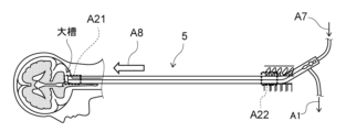
- FIG. 2 is a schematic diagram showing the brain disease treatment device according to this embodiment.
- the brain disease treatment system using the brain disease treatment device 5 includes a spinal subarachnoid space catheter system 2, a pump system 3, and an oxygenation mechanism 4. .
- the brain disease treatment device 5 is used in the spinal subarachnoid catheter system 2.
- the brain disease treatment device 5 is inserted into the subarachnoid space from near the lumbar vertebrae in a lateral position and delivered to the vicinity of the cisterna magna, and a high oxygen solution (oxygenated cerebrospinal fluid in this embodiment) is delivered to the distal end. is injected into the cerebrospinal fluid (CSF) present in the subarachnoid space, and the cerebrospinal fluid present in the subarachnoid space is aspirated at the proximal end and drained out of the patient's body.
- the high oxygen solution of this embodiment is an example of the "liquid" of the present invention.
- the pump system 3 includes a discharge pump 31 and an injection pump 32. As shown by arrow A1, arrow A2, and arrow A3 shown in FIG.
- the flow rate when aspirating (that is, discharging) cerebrospinal fluid from the subarachnoid space is, for example, approximately 0.1 mL/min or more and 500 mL/min or less.
- the suction flow rate (that is, the discharge flow rate) is not limited to 0.1 mL/min or more and 500 mL/min or less.
- the infusion pump 32 sucks the high oxygen solution supplied from the oxygenation mechanism 4 and injects it into the cerebrospinal fluid via the brain disease treatment device 5.
- the flow rate when injecting the high oxygen solution into the cerebrospinal fluid is, for example, approximately 0.1 mL/min or more and 500 mL/min or less. However, the injection rate is not limited to 0.1 mL/min or more and 500 mL/min or less.
- injection and drainage may be performed by a method in which a pump is used to perform natural injection, or a method in which injection and drainage are performed using potential energy, such as an intravenous drip, without using a pump.
- the oxygenation mechanism 4 includes an oxygen bubbling 41, an artificial cerebrospinal fluid bag 42, and an oxygen supply source 43.
- the artificial cerebrospinal fluid bag 42 stores artificial cerebrospinal fluid (aCSF) and supplies the artificial cerebrospinal fluid to the oxygen bubbling 41 as indicated by arrow A4 in FIG.
- the artificial cerebrospinal fluid can be composed of a liquid containing, for example, lactated Ringer's solution.
- the oxygen supply source 43 supplies oxygen to the oxygen bubbling 41 as indicated by arrow A5 shown in FIG.
- the oxygen bubbling 41 mixes cerebrospinal fluid supplied from the discharge pump 31, artificial cerebrospinal fluid supplied from the artificial cerebrospinal fluid bag 42, and oxygen supplied from the oxygen supply source 43 to generate oxygen.
- Oxygenated cerebrospinal fluid is produced, and the oxygenated cerebrospinal fluid is supplied to the injection pump 32 as a high oxygen solution as indicated by arrow A6 in FIG.
- the oxygenation mechanism 4 uses oxygen bubbling 41, but the hollow fibers are immersed in cerebrospinal fluid, oxygen is passed through the hollow fibers, and the cerebrospinal fluid is absorbed through the pores on the surface of the hollow fibers.
- the liquid may be oxygenated.
- the brain disease treatment device 5 is inserted into the subarachnoid space from near the lumbar vertebrae of the patient.
- the tip of the brain disease treatment device 5 is delivered near the patient's cisterna magna.
- the high oxygen solution is sent to the distal end of the brain disease treatment device 5 and injected into the cerebrospinal fluid present in the subarachnoid space.
- the arrow A1 shown in FIG. 2 corresponds to the arrow A1 shown in FIG.
- Arrow A7 shown in FIG. 2 corresponds to arrow A7 shown in FIG.
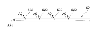
- FIG. 3 is a plan view showing the distal end portion of the brain disease treatment device according to this embodiment.
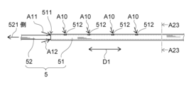
- FIG. 4 is a plan view showing the proximal end of the brain disease treatment device according to this embodiment.
- FIG. 5 is a sectional view taken along the cut plane A23-A23 shown in FIG. Note that FIG. 3 is an enlarged view showing the brain disease treatment device 5 in the area A21 shown in FIG. 2 in an enlarged manner.
- FIG. 4 is an enlarged view showing the brain disease treatment device 5 in area A22 shown in FIG. 2. As shown in FIG.
- the brain disease treatment device 5 includes a first tube 51 and a second tube 52.
- the first tube 51 has a plurality of holes 512 on the side surface thereof.
- the hole 512 communicates the inner lumen 513 (see FIG. 5) of the first tube 51 with the outside of the first tube 51.
- the distal end 511 of the first tube 51 is open and placed in the subarachnoid space near the lumbar vertebrae. As shown by arrows A10, A11, and A12 shown in FIG. 511 and the plurality of holes 512 into the space 53 (see FIG. 5) between the inner lumen 513 of the first tube 51 and the outside of the second tube 52. Note that, as described above with reference to FIG.
- the force for sucking the cerebrospinal fluid is provided by the discharge pump 31. Then, as indicated by the arrow A1 shown in FIGS. 1 and 2, the first tube 51 drains the cerebrospinal fluid out of the patient's body through the space 53.
- the outer diameter of the second tube 52 is smaller than the inner diameter of the first tube 51.
- the second tube 52 is positionable in the lumen 513 of the first tube 51 .
- the second pipe 52 is not connected to the first pipe 51 and is movable in the lumen 513 of the first pipe 51 along the longitudinal direction D1 (see FIG. 4) of the first pipe 51. It is. Since the tip 511 of the first tube 51 is open, the tip 521 of the second tube 52 can pass through the opening of the tip 511 of the first tube 51, as shown in FIG. be.
- the tip 521 of the second tube 52 can be exposed from the tip 511 of the first tube 51 in the longitudinal direction D1 of the first tube 51.
- the distance in the longitudinal direction D1 between the tip 511 of the first tube 51 and the tip 521 of the second tube 52 exposed from the tip 511 of the first tube 51 can be adjusted to a predetermined distance. be.
- the "predetermined distance” includes, for example, approximately 0 cm or more and 30 cm or less. If the distance between the tip 521 of the second tube 52 and the tip 511 of the first tube 51 is too close, the high oxygen solution injected into the cerebrospinal fluid through the second tube 52 will be sucked out by the first tube. This reduces the effectiveness of high oxygen solution injection.
- the maximum adjustable distance between the distal end 511 of the first tube 51 and the distal end 521 of the second tube 52 be 10 cm or more. Also, a position several centimeters cranial from the lumbar puncture site, which is assumed to be the placement position of the tip 511 of the first tube 51, from the cisterna magna, which is assumed to be the placement position of the tip 521 of the second tube 52. The distance to this point is thought to be 30cm to 50cm.
- the brain disease treatment device 5 can , is more preferable because it can accommodate various procedure policies that take into consideration the risks and the like during delivery of the second tube 52. For example, this includes one in which the distance between the distal end 511 of the first tube 51 and the distal end 521 of the second tube 52 can be adjusted from 0 cm to 30 cm. Moreover, if the maximum adjustable distance is 50 cm, the brain disease treatment device 5 is considered to be applicable to most patients. However, the "predetermined distance" in this specification is not limited to 0 cm or more and 30 cm or less.
- the second tube 52 has a plurality of holes 522 on the side surface of the second tube 52.
- the hole 522 communicates the inner lumen 523 (see FIG. 5) of the second tube 52 with the outside of the second tube 52.
- the distal end 521 of the second tube 52 is closed, passes through the opening of the distal end 511 of the first tube 51, and is disposed near the cisterna magna.
- the second tube 52 is inserted into the subarachnoid space of the patient and directs the high oxygen solution through the lumen 523 and the plurality of holes 522 into the vicinity of the cisterna magna. injected into the cerebrospinal fluid present in the subarachnoid space. Note that, as discussed above with respect to FIG. 1, the force for injecting the hyperoxic solution into the cerebrospinal fluid is provided by the infusion pump 32.
- the second tube 52 diffuses the oxygen-rich solution in all directions through the plurality of holes 522 around the injection point into the large space of the cisterna magna. It is thought that it is possible to do so.
- the configuration in which the distal end portion 521 of the second tube 52 is closed has been described, but the distal end portion 521 of the second tube 52 may have an open configuration. For example, if the space into which the high-oxygen solution is injected is not large, and if the tip 521 of the second tube 52 is configured to be open, the second tube 52 will inject the high-oxygen solution toward the front. High oxygen solution can be delivered deeper.
- the cross-sectional area of the space 53 between the outside of the second tube 52 and the inside of the first tube 51 is ICP (ICP).
- ICP intraluminal pressure
- the "predetermined ratio” is preferably about 0.5 times or more and 2 times or less, for example. However, the "predetermined ratio" in this specification is not limited to 0.5 times or more and 2 times or less.
- a first specific example of a treatment method using the brain disease treatment device 5 of this embodiment will be described below with reference to FIGS. 1 and 4.
- a puncture needle of a puncture device (not shown) is inserted into the subarachnoid space through the patient's lumbar vertebrae.
- the first tube 51 is inserted into the inner lumen of the puncture needle of the puncture device and inserted into the subarachnoid space, and the distal end 511 of the first tube 51 is placed at a position several centimeters cephalad from the lumbar puncture site. Detained at.
- the puncture needle is removed from the lumbar vertebrae, and the proximal end of the first tube 51 is inserted into the first insertion port 612 of the treatment device connector 6 and fixed.
- the second tube 52 is inserted into the inner cavity of the first tube 51 by inserting the second tube 52 into the second insertion port 622 of the therapeutic device connector 6, and the second tube 52 is inserted into the inner cavity of the first tube 51.
- the distal end 521 of is delivered cranially into the subarachnoid space and placed near the cisterna magna.
- the infusion pump 32 connected to the proximal end of the lumen of the second tube 52 is activated to infuse the high oxygen solution into the cerebrospinal cord in the cisterna magna of the subarachnoid space through the hole 522 of the second tube 52.
- the evacuation pump 31 connected to the proximal end of the lumen of the first tube 51 is activated, and the distal end of the first tube 51 is activated. Through opening 511 and hole 512, approximately the same amount of cerebrospinal fluid as the amount of hyperoxic solution injected is drained out of the body.
- a puncture needle of a puncture device (not shown) is inserted into the subarachnoid space through the patient's lumbar vertebrae.
- a guide wire (not shown) is inserted into the lumen of the puncture needle of the puncture device and inserted into the subarachnoid space.
- only the puncture device is removed from the lumbar vertebrae while the guide wire remains inserted into the subarachnoid space.
- only the guide wire is inserted from the lumbar vertebrae to the subarachnoid space.
- a guide wire is inserted into the lumen of the first tube 51, the first tube 51 is advanced along the guide wire, and the first tube 51 is inserted into the subarachnoid space.
- only the guide wire is removed while the first tube 51 remains inserted into the subarachnoid space from the lumbar vertebrae. In this case, only the first tube 51 is inserted into the subarachnoid space from the lumbar vertebrae.
- the second tube 52 is inserted into the lumen of the first tube 51, and the distal end 521 of the second tube 52 is delivered toward the cranial side of the subarachnoid space and placed near the cisterna magna. . Then, the infusion pump 32 connected to the proximal end of the lumen of the second tube 52 is activated to infuse the high oxygen solution into the cerebrospinal cord in the cisterna magna of the subarachnoid space through the hole 522 of the second tube 52.
- the evacuation pump 31 connected to the proximal end of the lumen of the first tube 51 is activated, and the distal end of the first tube 51 is activated.
- the distal end of the first tube 51 is activated.
- approximately the same amount of cerebrospinal fluid as the amount of hyperoxic solution injected is drained out of the body. This increases the oxygen concentration in the cerebrospinal fluid and supplies oxygen to areas of the brain that lack oxygen, thereby preventing or reducing the progression of cerebral infarction.
- the first tube 51 and the second tube 52 are removed from the patient's lumbar vertebrae.
- the first tube 51 and the second tube 52 are inserted into the subarachnoid space from the patient's lumbar vertebrae.
- the first tube 51 and the second tube 52 may be inserted into the subarachnoid space from the head.
- two pumps, the infusion pump 32 and the discharge pump 31 are used to inject a high oxygen solution and discharge the cerebrospinal fluid.
- the patient may then inject a hyperoxic solution and drain the cerebrospinal fluid.
- cerebrospinal fluid discharged from the patient's subarachnoid space may be oxygenated by the oxygenation mechanism 4 and injected into the patient's subarachnoid space.
- the brain disease treatment device 5 according to the present embodiment, after the first tube 51 and the second tube 52 are inserted into the subarachnoid space from one puncture site near the lumbar vertebrae, the second tube 52 is inserted into the subarachnoid space. , can move through the lumen 513 of the first tube 51 and can be exposed from the distal end 511 of the first tube 51 in the longitudinal direction D1. As a result, the brain disease treatment device 5 according to the present embodiment can inject the high oxygen solution into the cerebrospinal fluid and discharge the cerebrospinal fluid at one puncture site, and can inject the high oxygen solution into the brain.
- the injection position of the second tube 52 for injecting the spinal fluid and the discharge position of the first tube 51 for draining the cerebrospinal fluid out of the patient's body can be adjusted independently.
- a cerebral infarction it becomes possible to adopt an arrangement that can efficiently deliver a high-oxygen solution depending on the patient's body shape and the area where the cerebral infarction occurs, thereby reducing the amount of oxygen that occurs in brain cells. Damage can be suppressed.
- a cerebral infarction it becomes possible to arrange a tube appropriately according to the location of the onset, and it is possible to efficiently administer a high oxygen solution and suppress damage caused to brain cells.
- the brain disease treatment device 5 there is a gap between the distal end 511 of the first tube 51 and the distal end 521 of the second tube 52 exposed from the distal end 511 of the first tube 51.
- the distance in the longitudinal direction D1 can be adjusted to a predetermined distance or more. Therefore, the discharge position of the first tube 51 and the injection position of the second tube 52 can be separated by a predetermined distance or more in the longitudinal direction D1. Therefore, it is possible to prevent the high oxygen solution injected into the cerebrospinal fluid through the second tube 52 from being immediately sucked into the first tube 51 and discharged from the patient's body. Thereby, it is possible to efficiently discharge the cerebrospinal fluid and inject the high oxygen solution into the cerebrospinal fluid.
- the cross-sectional area of the space 53 is within a predetermined ratio to the cross-sectional area of the lumen 523 of the second tube 52, so that the cerebrospinal fluid is Cerebrospinal fluid can be efficiently drained and injected while maintaining a balance between draining and injecting fluid into the cerebrospinal fluid.
- FIG. 6 is a perspective view illustrating a specific example of the first tube of this embodiment.
- FIG. 7 is a plan view showing the first tube of this specific example. Note that FIG. 7 schematically shows a state in which each hole 512 that appears when the first tube 51 is rotated in the circumferential direction about the axis A31 of the first tube 51 is projected onto a predetermined plane.
- the plurality of holes 512 are arranged in a spiral shape on the side surface of the first tube 51. Specifically, as shown in FIG. 7, the plurality of holes 512 are provided at different positions in the circumferential direction of the first pipe 51 and spaced apart from each other by substantially equal intervals L1. ing. Further, the plurality of holes 512 are provided at mutually different positions in the longitudinal direction D1 (that is, in the direction of the axis A31) and at positions separated from each other by substantially equal intervals L2. Note that the direction of the spiral may be either right-handed or left-handed toward the tip.
- the plurality of holes 512 are arranged spirally on the side of the first tube 51, when the first tube 51 is inserted into the subarachnoid space and aspirates cerebrospinal fluid, the patient's Even if tissue in the living body sticks to any of the plurality of holes 512, it is possible to prevent all of the plurality of holes 512 from being blocked by the tissue. This can prevent the first tube 51 from being unable to suction and drain the cerebrospinal fluid.
- FIG. 6 and FIG. 7 illustrate the case where the plurality of holes 512 are arranged in a spiral shape
- the arrangement form of the plurality of holes 512 is not limited to the spiral shape.
- the plurality of holes 512 may be randomly arranged in the longitudinal direction D1 and the circumferential direction.
- the plurality of holes 512 are located at the same position in the circumferential direction of the first tube 51, but at different positions in the longitudinal direction D1, and are spaced apart from each other at substantially equal intervals L2. It may be provided in a different position.
- the plurality of holes 512 may be provided at the same position in the longitudinal direction D1, at different positions in the circumferential direction of the first tube 51, and at substantially equal intervals L1 apart from each other. . Even in such a case, as in the case where the plurality of holes 512 are arranged spirally, it is possible to prevent all of the plurality of holes 512 from being blocked by tissue, and the first tube 51 This can prevent the inability to aspirate and drain cerebrospinal fluid.
- FIG. 8 is a cross-sectional view showing the connector for a treatment device according to this embodiment.
- the treatment device connector 6 has a first holding part 61 , a second holding part 62 , and an outlet part 63 .
- the first holding part 61 has a first contact part 611.
- the inner diameter of the first close contact portion 611 is equal to or less than the outer diameter of the first tube 51 .
- the first holding portion 61 holds the first tube 51 inserted from the first insertion port 612 in the direction of arrow A13 shown in FIG. 8 at the first close contact portion 611.
- the first contact portion 611 has a first tapered portion 613.
- the first tapered portion 613 is a portion whose inner diameter gradually decreases in the direction in which the first tube 51 is inserted from the first insertion port 612 (ie, in the direction of arrow A13).
- the first tube 51 is reliably brought into close contact with the first tapered portion 613 of the first close contact portion 611 in a fluid-tight manner. Thereby, the first tube 51 can be fixed inside the first holding part 61.
- the second holding part 62 has a second contact part 621.
- the inner diameter of the second close contact portion 621 is equal to or less than the outer diameter of the second tube 52 .
- the second holding portion 62 holds the second tube 52 inserted from the second insertion port 622 in the direction of arrow A14 shown in FIG. 8 at the second close contact portion 621.
- the second contact portion 621 has a second tapered portion 623.
- the second tapered portion 623 is a portion whose inner diameter gradually decreases in the direction in which the second tube 52 is inserted from the second insertion port 622 (ie, in the direction of arrow A14). Since the second close contact portion 621 has the second tapered portion 623, the second pipe 52 is reliably brought into close contact with the second tapered portion 623 of the second close contact portion 621 in a liquid-tight manner.
- the outlet part 63 is sandwiched between the first holding part 61 and the second holding part 62 and is fixed to the first holding part 61 and the second holding part 62.
- the first holding part 61, the second holding part 62, and the outlet part 63 may be formed integrally, or may be formed separately and joined to each other.
- the outlet portion 63 has a flow path 631 through which the cerebrospinal fluid passing through the space 53 flows.
- the cerebrospinal fluid passing through space 53 is cerebrospinal fluid that has been aspirated into space 53 through the opening in tip 511 and the plurality of holes 512.
- the cerebrospinal fluid that has flowed through the channel 631 is discharged from an outlet 632 provided in the outlet section 63. Note that the arrow A1 shown in FIG. 8 corresponds to the arrow A1 shown in FIGS. 1 and 2.
- the second The close contact portion 621 exists inside the first close contact portion 611 .
- the second tube 52 inserted from the second insertion port 622 can be inserted into the lumen 513 of the first tube 51 fixed to the first holding part 61, It is possible to penetrate the first tube 51.
- the high oxygen solution is injected into the cerebrospinal fluid present in the subarachnoid space near the cisterna magna through the lumen 523 of the second tube 52.
- arrow A7 shown in FIG. 8 corresponds to arrow A7 shown in FIGS. 1 and 2.
- the arrow A1 shown in FIG. is discharged from the outlet 632.
- the first tube 51 of the brain disease treatment device 5 is inserted into the patient's body through a spinal needle punctured into the patient's body, and the spinal needle is removed.
- the first holding part 61 can hold the first tube 51 inserted through the first insertion port 612 at the first close contact part 611 .
- the second holding portion 62 can hold the second tube 52 inserted through the second insertion port 622 at the second close contact portion 621 .
- the second close contact portion 621 exists inside the first close contact portion 611.
- the second tube 52 can be easily placed through the second close contact portion 621 without having to be aligned with the inner lumen 513 of the first tube 51. can be moved longitudinally (axially).
- the outlet portion 63 has a channel 631 through which the cerebrospinal fluid passing through the space 53 flows, and also has an outlet 632 of the channel 631.
- the therapeutic device connector 6 according to the present embodiment is configured such that, after the spinal needle is removed, the first tube 51 It is said that it can be attached to the pipe 51.
- the second tube 52 can be easily placed in the inner cavity 513 of the first tube 51, and the second tube 52 can be easily placed in the inner cavity 513 of the first tube 51.
- the inner lumen 513 of the tube 51 of No. 1 can be easily moved in the longitudinal direction (axial direction).
- the therapeutic device connector 6 is configured to insert the first tube 51 into the patient's body after the spinal needle is removed.
- the cerebrospinal fluid discharged from the proximal end 514 of the first tube 51 can pass through the channel 631 of the outlet section 63 and be discharged out of the body.
- the first tube 51 is reliably and fluid-tightly adhered to the first tapered portion 613 of the first contact portion 611.
- the second pipe 52 is in close contact with the second tapered portion 623 of the second close contact portion 621 in a liquid-tight manner. Therefore, due to the negative pressure generated when the first tube 51 aspirates cerebrospinal fluid and discharges it out of the patient's body, the gap between the first tube 51 and the first contact portion 611 and between the second tube 52 and It is possible to prevent a gap from forming between the second contact portion 621 and the second contact portion 621 .
- the space between the first tube 51 and the first contact portion 611 and between the second tube 52 and the second It is possible to suppress air from entering the inside of the first tube 51 from between the close contact portion 621 and a decrease in the efficiency of draining the cerebrospinal fluid.
- the connector fixed to the patient's body surface by the treatment device connector fixing tool 7 affixed to an appropriate location on the patient's body surface is the treatment device connector 6 described above with reference to FIG.
- the treatment device connected to the treatment device connector 6 is the brain disease treatment device 5 described above with reference to FIGS. 1 to 7. Therefore, descriptions of the connector fixed to the patient's body surface by the treatment device connector fixture 7 and the treatment device connected to the treatment device connector 6 will be omitted as appropriate, and the following will focus on the treatment device connector fixture 7.
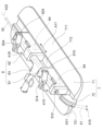
- FIG. 9 is a perspective view showing a specific example of the treatment device connector fixture according to the present embodiment and the treatment device connector according to the present embodiment.
- the treatment device connector fixture 7 includes a fixture main body 71 and a tube holding part 72.
- the fixture main body 71 has a body surface attachment portion 711 and a connector attachment portion 712. As shown in FIG. 9, the body surface attachment portion 711 has a plate shape and is attached to the patient's body surface.
- the connector attachment portion 712 attaches the treatment device connector 6 to the fixture body 71.
- the connector attachment portion 712 is a groove formed in the fixture main body 71 along the longitudinal direction D1 (see FIG. 4).
- a magnet 64 is attached to the lower surface of each of the first holding part 61 and the second holding part 62.
- the lower surface of each of the first holding part 61 and the second holding part 62 is a surface facing the connector attachment part 712.
- the treatment device connector 6 is attached to the connector attachment portion 712 by attracting the magnet 64 to the connector attachment portion 712 .
- an arrow A17 shown in FIG. The second tube 52 held by the second holding part 62 can be adjusted along the direction of the axis A32.
- the tube holding part 72 is fixed to the distal end of the fixture body 71 and can hold the first tube 51.
- a groove having substantially the same diameter as the outer diameter of the first tube 51 is formed in a portion where the tube holding portion 72 holds the first tube 51 .
- the tube holding portion 72 has a curved portion 721 provided at a portion with which the first tube 51 comes into contact. Thereby, the tube holding part 72 can suppress the first tube 51 from kinking (breaking, etc.) in the vicinity of the puncture site 515.
- the connector attachment portion 712 positions the attachment position of the treatment device connector 6 on the axis A31 of the first tube 51 held by the first holding portion 61. and along the direction of the axis A32 of the second tube 52 held by the second holding part 62. Therefore, regardless of the length of the first tube 51 inserted into the subarachnoid space, the therapeutic device connector fixing tool 7 can be used at the position where the first tube 51 is inserted into the subarachnoid space (i.e., the puncture point). 515) to the patient's body surface at any position within a certain range along the direction of the axis A31 of the first tube 51. This can prevent the first tube 51 from kinking or falling off.
- the first holding part 61 has a first pinching part 614.
- the first pinching portion 614 is rotatably supported by a first support shaft 615 provided on the first holding portion 61.
- the first pinching part 614 pinches and fixes the first tube 51 by rotating in the closing direction with respect to the first holding part 61.
- the second holding portion 62 has a second sandwiching portion 624 .
- the second pinching portion 624 is rotatably supported by a second support shaft 625 provided on the second holding portion 62.
- the second pinching part 624 pinches and fixes the second tube 52 by rotating in the closing direction with respect to the second holding part 62 .
- the treatment device connector 6 can fix the injection position of the high oxygen solution through the second tube 52 and the discharge position (i.e., suction position) of the cerebrospinal fluid through the first tube 51 after adjusting them. can.
Abstract
Le dispositif thérapeutique pour maladies cérébrales (5) selon la présente invention est pourvu d'un premier tube (51) et d'un second tube (52) qui a un diamètre externe plus petit que le diamètre interne du premier tube (51), peut être placé dans une cavité interne du premier tube (51) et peut se déplacer dans la cavité interne du premier tube (51). Le premier tube (51) est inséré dans une cavité subarachnoïdienne chez un patient, et évacue un fluide céphalorachidien présent dans la cavité subarachnoïdienne vers l'extérieur du corps du patient à travers un espace formé entre la cavité interne du premier tube (51) et l'extérieur du second tube (52). Le second tube (52) est inséré dans la cavité subarachnoïdienne, et injecte un liquide dans le liquide céphalorachidien présent dans la cavité subarachnoïdienne à travers la cavité interne du second tube (52). Une partie d'extrémité (521) du second tube (52) peut être exposée à partir d'une partie d'extrémité (511) du premier tube (51) dans la direction de la longueur (D1) du premier tube (51).
Applications Claiming Priority (2)
| Application Number | Priority Date | Filing Date | Title |
|---|---|---|---|
| JP2022-047262 | 2022-03-23 | ||
| JP2022047262 | 2022-03-23 |
Publications (1)
| Publication Number | Publication Date |
|---|---|
| WO2023181979A1 true WO2023181979A1 (fr) | 2023-09-28 |
Family
ID=88101275
Family Applications (1)
| Application Number | Title | Priority Date | Filing Date |
|---|---|---|---|
| PCT/JP2023/009221 WO2023181979A1 (fr) | 2022-03-23 | 2023-03-10 | Dispositif thérapeutique pour maladies cérébrales, raccord pour dispositifs thérapeutiques, et outil de fixation de raccord pour dispositifs thérapeutiques |
Country Status (1)
| Country | Link |
|---|---|
| WO (1) | WO2023181979A1 (fr) |
Citations (8)
| Publication number | Priority date | Publication date | Assignee | Title |
|---|---|---|---|---|
| JP2002501792A (ja) * | 1998-02-03 | 2002-01-22 | セイラント インターベンショナル システムズ, インコーポレイテッド | 虚血を処理するための方法およびシステム |
| JP2005535393A (ja) * | 2002-08-12 | 2005-11-24 | ブレグ インコーポレイテッド | 一体化された注入・吸引システムとその方法 |
| JP2009506817A (ja) * | 2005-09-02 | 2009-02-19 | エステル エンタープライゼズ リミテッド | 流動体置換カテーテルシステム |
| JP2015524321A (ja) * | 2012-08-10 | 2015-08-24 | イラス アクチエボラグ | 流体交換カテーテルおよび流体交換カテーテルの閉塞を除去する方法 |
| JP2015211828A (ja) * | 2014-04-14 | 2015-11-26 | 国立大学法人 岡山大学 | 溶質および/または溶媒の局所での浸透および拡散を制御する装置、システム、および方法 |
| JP2020536618A (ja) * | 2017-10-05 | 2020-12-17 | ミネトロニクス, インコーポレイテッド | 中枢神経系に沿って治療を行うためのシステム、カテーテル、及び方法 |
| WO2021192539A1 (fr) * | 2020-03-27 | 2021-09-30 | テルモ株式会社 | Cathéter et système de cathéter |
| WO2021192538A1 (fr) * | 2020-03-27 | 2021-09-30 | テルモ株式会社 | Cathéter |
-
2023
- 2023-03-10 WO PCT/JP2023/009221 patent/WO2023181979A1/fr unknown
Patent Citations (8)
| Publication number | Priority date | Publication date | Assignee | Title |
|---|---|---|---|---|
| JP2002501792A (ja) * | 1998-02-03 | 2002-01-22 | セイラント インターベンショナル システムズ, インコーポレイテッド | 虚血を処理するための方法およびシステム |
| JP2005535393A (ja) * | 2002-08-12 | 2005-11-24 | ブレグ インコーポレイテッド | 一体化された注入・吸引システムとその方法 |
| JP2009506817A (ja) * | 2005-09-02 | 2009-02-19 | エステル エンタープライゼズ リミテッド | 流動体置換カテーテルシステム |
| JP2015524321A (ja) * | 2012-08-10 | 2015-08-24 | イラス アクチエボラグ | 流体交換カテーテルおよび流体交換カテーテルの閉塞を除去する方法 |
| JP2015211828A (ja) * | 2014-04-14 | 2015-11-26 | 国立大学法人 岡山大学 | 溶質および/または溶媒の局所での浸透および拡散を制御する装置、システム、および方法 |
| JP2020536618A (ja) * | 2017-10-05 | 2020-12-17 | ミネトロニクス, インコーポレイテッド | 中枢神経系に沿って治療を行うためのシステム、カテーテル、及び方法 |
| WO2021192539A1 (fr) * | 2020-03-27 | 2021-09-30 | テルモ株式会社 | Cathéter et système de cathéter |
| WO2021192538A1 (fr) * | 2020-03-27 | 2021-09-30 | テルモ株式会社 | Cathéter |
Similar Documents
| Publication | Publication Date | Title |
|---|---|---|
| US8246587B2 (en) | Infiltration cannula | |
| US10549068B2 (en) | Catheter hole having an inclined trailing edge | |
| CA2467406C (fr) | Ensemble catheter d'administration de medicament a ballonnet gonflable | |
| ES2809236T3 (es) | Sistemas para mejorar la eficiencia de distribuciones de agujeros de catéter | |
| US8512292B2 (en) | Infiltration cannula | |
| CA2639956C (fr) | Catheter pour reflux reduit dans l'application tissulaire ciblee d'un agent therapeutique | |
| US11020526B2 (en) | Sprinkler cannula | |
| US5997524A (en) | Catheter assembly for percutaneous access to subcutaneous port | |
| US20100100061A1 (en) | Method and system for the use of hollow fiber catheters in topical applications | |
| EP2385854B1 (fr) | Cathéters intracrâniens optimisés pour apport d'agents thérapeutiques renforcé par convection | |
| US20190167964A1 (en) | Percutaneous access apparatus | |
| CA2825375C (fr) | Orifice de catheter ayant un bord de fuite incline | |
| AU2011279479A1 (en) | A catheter hole having an inclined trailing edge | |
| WO2023181979A1 (fr) | Dispositif thérapeutique pour maladies cérébrales, raccord pour dispositifs thérapeutiques, et outil de fixation de raccord pour dispositifs thérapeutiques | |
| JP6418645B2 (ja) | 溶質および/または溶媒の局所での浸透および拡散を制御する装置、システム、および方法 | |
| WO2001091830A1 (fr) | Systeme implantable d'administration de liquides | |
| WO2014128824A1 (fr) | Instrument pour traitement médical |
Legal Events
| Date | Code | Title | Description |
|---|---|---|---|
| 121 | Ep: the epo has been informed by wipo that ep was designated in this application |
Ref document number: 23774578 Country of ref document: EP Kind code of ref document: A1 |