WO2023181979A1 - Therapeutic device for brain diseases, connector for therapeutic devices, and connector fixing tool for therapeutic devices - Google Patents
Therapeutic device for brain diseases, connector for therapeutic devices, and connector fixing tool for therapeutic devices Download PDFInfo
- Publication number
- WO2023181979A1 WO2023181979A1 PCT/JP2023/009221 JP2023009221W WO2023181979A1 WO 2023181979 A1 WO2023181979 A1 WO 2023181979A1 JP 2023009221 W JP2023009221 W JP 2023009221W WO 2023181979 A1 WO2023181979 A1 WO 2023181979A1
- Authority
- WO
- WIPO (PCT)
- Prior art keywords
- tube
- treatment device
- lumen
- connector
- patient
- Prior art date
Links
- 208000014644 Brain disease Diseases 0.000 title claims abstract description 56
- 230000001225 therapeutic effect Effects 0.000 title claims abstract description 28
- 210000001175 cerebrospinal fluid Anatomy 0.000 claims abstract description 88
- 239000007788 liquid Substances 0.000 claims abstract description 22
- 239000001301 oxygen Substances 0.000 claims description 59
- 229910052760 oxygen Inorganic materials 0.000 claims description 59
- QVGXLLKOCUKJST-UHFFFAOYSA-N atomic oxygen Chemical compound [O] QVGXLLKOCUKJST-UHFFFAOYSA-N 0.000 claims description 55
- 210000002330 subarachnoid space Anatomy 0.000 claims description 48
- 238000003780 insertion Methods 0.000 claims description 29
- 230000037431 insertion Effects 0.000 claims description 29
- 230000007423 decrease Effects 0.000 claims description 11
- 239000000243 solution Substances 0.000 description 41
- 238000002347 injection Methods 0.000 description 25
- 239000007924 injection Substances 0.000 description 25
- 238000000034 method Methods 0.000 description 15
- 210000003703 cisterna magna Anatomy 0.000 description 13
- 206010008118 cerebral infarction Diseases 0.000 description 11
- 208000026106 cerebrovascular disease Diseases 0.000 description 11
- 239000012530 fluid Substances 0.000 description 11
- 210000004958 brain cell Anatomy 0.000 description 7
- 238000001802 infusion Methods 0.000 description 7
- 210000001519 tissue Anatomy 0.000 description 7
- 230000005587 bubbling Effects 0.000 description 6
- 230000000222 hyperoxic effect Effects 0.000 description 6
- 238000006213 oxygenation reaction Methods 0.000 description 6
- 238000010586 diagram Methods 0.000 description 4
- 210000004556 brain Anatomy 0.000 description 3
- 239000012510 hollow fiber Substances 0.000 description 3
- 102000003978 Tissue Plasminogen Activator Human genes 0.000 description 2
- 108090000373 Tissue Plasminogen Activator Proteins 0.000 description 2
- 230000017531 blood circulation Effects 0.000 description 2
- 230000037237 body shape Effects 0.000 description 2
- 239000000839 emulsion Substances 0.000 description 2
- 238000007917 intracranial administration Methods 0.000 description 2
- 238000009593 lumbar puncture Methods 0.000 description 2
- 235000015097 nutrients Nutrition 0.000 description 2
- 229960000187 tissue plasminogen activator Drugs 0.000 description 2
- 208000006011 Stroke Diseases 0.000 description 1
- 230000015572 biosynthetic process Effects 0.000 description 1
- BPKIGYQJPYCAOW-FFJTTWKXSA-I calcium;potassium;disodium;(2s)-2-hydroxypropanoate;dichloride;dihydroxide;hydrate Chemical compound O.[OH-].[OH-].[Na+].[Na+].[Cl-].[Cl-].[K+].[Ca+2].C[C@H](O)C([O-])=O BPKIGYQJPYCAOW-FFJTTWKXSA-I 0.000 description 1
- 230000003247 decreasing effect Effects 0.000 description 1
- 230000002950 deficient Effects 0.000 description 1
- 238000007599 discharging Methods 0.000 description 1
- 201000010099 disease Diseases 0.000 description 1
- 208000037265 diseases, disorders, signs and symptoms Diseases 0.000 description 1
- 238000001990 intravenous administration Methods 0.000 description 1
- 210000003140 lateral ventricle Anatomy 0.000 description 1
- 230000000149 penetrating effect Effects 0.000 description 1
- 239000011148 porous material Substances 0.000 description 1
- 238000005381 potential energy Methods 0.000 description 1
- 230000010410 reperfusion Effects 0.000 description 1
- 210000003625 skull Anatomy 0.000 description 1
- 238000002560 therapeutic procedure Methods 0.000 description 1
- 238000013151 thrombectomy Methods 0.000 description 1
Images


Classifications
-
- A—HUMAN NECESSITIES
- A61—MEDICAL OR VETERINARY SCIENCE; HYGIENE
- A61M—DEVICES FOR INTRODUCING MEDIA INTO, OR ONTO, THE BODY; DEVICES FOR TRANSDUCING BODY MEDIA OR FOR TAKING MEDIA FROM THE BODY; DEVICES FOR PRODUCING OR ENDING SLEEP OR STUPOR
- A61M1/00—Suction or pumping devices for medical purposes; Devices for carrying-off, for treatment of, or for carrying-over, body-liquids; Drainage systems
-
- A—HUMAN NECESSITIES
- A61—MEDICAL OR VETERINARY SCIENCE; HYGIENE
- A61M—DEVICES FOR INTRODUCING MEDIA INTO, OR ONTO, THE BODY; DEVICES FOR TRANSDUCING BODY MEDIA OR FOR TAKING MEDIA FROM THE BODY; DEVICES FOR PRODUCING OR ENDING SLEEP OR STUPOR
- A61M25/00—Catheters; Hollow probes
Definitions
- the present invention relates to a brain disease treatment device used for the treatment of brain diseases, a treatment device connector connected to the treatment device, and a treatment device connector fixture for fixing the treatment device connector to the body surface of a patient.
- a cerebral infarction occurs as a brain disease
- the blood flow that supplies oxygen to brain cells is blocked, potentially causing damage to the brain cells. Therefore, when cerebral infarction occurs, early reperfusion of blood flow is necessary.
- hyperacute treatment e.g., tissue plasminogen activator (t-PA) administration, mechanical thrombectomy therapy (MT), etc.
- t-PA tissue plasminogen activator
- MT mechanical thrombectomy therapy
- Patent Document 1 discloses a method and system for providing early stroke treatment.
- a nutrient emulsion is withdrawn from the cisterna magna via a conduit whose tip is inserted in the vicinity of the cisterna magna.
- the oxygenated nutrient emulsion is also injected into the lateral ventricle through an infusion cannula attached to the skull via a retainer.
- the injection position of the high oxygen solution and the suction position of the cerebrospinal fluid (in other words, it is desirable to adjust the catheter position (i.e., the ejection position) independently in the insertion direction (i.e., the longitudinal direction) of the catheter.
- the present invention has been made in view of the above-mentioned circumstances, and it is possible to inject and discharge at one puncture site, and the injection and discharge positions can be adjusted independently after being inserted into a living body. It is an object of the present invention to provide a disease treatment device, a treatment device connector connected to the treatment device, and a treatment device connector fixture for fixing the treatment device connector to the body surface of a patient.
- the problem is to provide a first tube having an outer diameter smaller than an inner diameter of the first tube, which can be placed in the inner lumen of the first tube, and which is movable in the inner lumen of the first tube.
- a second tube the first tube is inserted into the subarachnoid space of the patient, and the cerebrospinal fluid present in the subarachnoid space is transferred between the lumen of the first tube and the second tube. and the second tube is inserted into the subarachnoid space and directs liquid through the lumen of the second tube into the subarachnoid space. and the end of the second tube is exposed from the end of the first tube in the longitudinal direction of the first tube.
- the outer diameter of the second tube is smaller than the inner diameter of the first tube.
- the second tube is positionable and movable within the lumen of the first tube.
- the first tube is inserted into the patient's subarachnoid space and directs the cerebrospinal fluid present in the subarachnoid space through the space between the lumen of the first tube and the outside of the second tube to outside the patient's body. to be discharged.
- a second tube is inserted into the subarachnoid space and injects fluid through the lumen of the second tube into the cerebrospinal fluid present in the subarachnoid space.
- the end of the second tube can be exposed from the end of the first tube in the longitudinal direction of the first tube.
- the second tube can move within the lumen of the first tube and Can be exposed from the ends. This allows for the injection of fluid into the cerebrospinal fluid and the drainage of the cerebrospinal fluid at one puncture point, and the injection location of the second tube for injecting the fluid into the cerebrospinal fluid and the cerebrospinal fluid.
- the discharge position of the first tube which discharges the patient's body from the patient's body can be adjusted independently.
- the longitudinal direction between the end of the first tube and the end of the second tube exposed from the end of the first tube is is characterized in that the distance can be adjusted to a predetermined distance or more.
- the longitudinal distance between the end of the first tube and the end of the second tube exposed from the end of the first tube is a predetermined distance. It is possible to adjust more than that. Therefore, the discharge position of the first tube and the injection position of the second tube can be separated by a predetermined distance or more in the longitudinal direction. Therefore, it is possible to prevent the fluid injected into the cerebrospinal fluid through the second tube from being immediately sucked into the first tube and discharged from the patient's body. Thereby, it is possible to efficiently discharge the cerebrospinal fluid and inject fluid into the cerebrospinal fluid.
- a cross-sectional area of a space between the inner lumen of the first tube and the outside of the second tube in a cut plane perpendicular to the longitudinal direction. is within a predetermined ratio to the cross-sectional area of the inner lumen of the second tube.
- the cross-sectional area of the space between the lumen of the first tube and the outside of the second tube in the cut plane in the direction perpendicular to the longitudinal direction is the same as that of the second tube. is within a predetermined ratio to the cross-sectional area of the lumen of the tube.
- the first tube has a plurality of holes that communicate between the inner lumen of the first tube and the outside of the first tube.
- the plurality of holes are provided at different positions in the circumferential direction of the first tube and spaced apart from each other at substantially equal intervals.
- the first tube connects the cerebrospinal cord from the outside of the first tube to the inner lumen of the first tube through the plurality of holes provided on the side surface of the first tube. Aspirate the fluid and drain it out of the patient's body.
- the plurality of holes in the first tube are provided at different positions in the circumferential direction of the first tube and spaced apart from each other at substantially equal intervals. Therefore, when the first tube is inserted into the subarachnoid space to aspirate cerebrospinal fluid, even if the tissue in the patient's body sticks to one of the multiple holes, all of the multiple holes are covered with tissue. It is possible to prevent blockage due to This can prevent the first tube from being unable to suction and drain the cerebrospinal fluid.
- the plurality of holes are provided at different positions in the longitudinal direction and spaced apart from each other at substantially equal intervals.
- the plurality of holes of the first tube are located at different positions in the circumferential direction and longitudinal direction of the first tube and are spaced apart from each other at substantially equal intervals. established in The plurality of holes are therefore arranged in a helical manner on the side of the first tube. Therefore, when the first tube is inserted into the subarachnoid space to aspirate cerebrospinal fluid, even if the tissue in the patient's body sticks to one of the multiple holes, all of the multiple holes are covered with tissue. It is possible to further suppress the occurrence of blockage. Thereby, it is possible to further prevent the first tube from being unable to suction and drain the cerebrospinal fluid.
- the brain disease treatment device is preferably characterized in that the liquid is a high oxygen solution.
- the brain disease treatment device it is possible to inject a high oxygen solution into the cerebrospinal fluid and to discharge the cerebrospinal fluid at one puncture site, and the high oxygen solution can be injected into the cerebrospinal fluid.
- the injection position of the second tube for draining the cerebrospinal fluid and the discharge position of the first tube for draining the cerebrospinal fluid out of the patient's body can be adjusted independently.
- a cerebral infarction it becomes possible to adopt an arrangement that can efficiently deliver a high-oxygen solution depending on the patient's body shape and the area where the cerebral infarction occurs, thereby reducing the amount of oxygen that occurs in brain cells. Damage can be suppressed.
- a cerebral infarction it becomes possible to arrange a tube appropriately according to the location of the onset, and it is possible to efficiently administer a high oxygen solution and suppress damage caused to brain cells.
- the problem is to provide a first tube having an outer diameter smaller than an inner diameter of the first tube, which can be placed in the inner lumen of the first tube, and which is movable in the inner lumen of the first tube.
- a second tube the first tube is inserted into a biological lumen of a patient, and the liquid present in the biological lumen is transferred between the lumen of the first tube and the second tube.
- the second tube is inserted into the body lumen, injecting a liquid into the body lumen through the lumen of the second tube;
- a second holding portion that holds the second tube inserted from the second insertion port in the second close contact portion; and an inner lumen of the first tube and an outside of the second tube.
- the second close contact portion is located inside the first close contact portion when viewed along the axial direction of any one of the second tubes held in the second tube. Solved by connectors for therapeutic devices.
- the first holding portion has a first contact portion whose inner diameter is equal to or less than the outer diameter of the first tube of the treatment device, and the first holding portion is inserted through the first insertion port.
- the first tube of the treated treatment device is held in the first contact portion.
- the second holding part has a second close contact part whose inner diameter is less than or equal to the outer diameter of the second tube of the treatment device, and the second holding part has a second contact part whose inner diameter is less than or equal to the outer diameter of the second tube of the treatment device, and the second holding part has a second contact part that has an inner diameter that is less than or equal to the outer diameter of the second tube of the treatment device. Hold at the close contact part.
- the first holding part is inserted into the patient's body from the first insertion port.
- the inserted first tube of the treatment device can be held in the first abutment.
- the second holding portion can hold the second tube of the treatment device inserted from the second insertion port in the second close contact portion.
- the second tube The close contact portion exists inside the first close contact portion.
- the second tube of the treatment device can be easily placed in the lumen of the first tube of the treatment device through the second close contact portion, and can be easily moved through the lumen of the first tube of the treatment device. I can do it.
- the outlet portion has a flow path through which a liquid passes through the space between the inner lumen of the first tube of the treatment device and the outside of the second tube of the treatment device, and has an outlet of the flow path. .
- the connector for a therapeutic device according to the present invention allows the first tube of the therapeutic device to be inserted into a patient's body using a spinal needle, for example, after the spinal needle is removed. It is said that it can be attached to the first tube.
- the second tube of the treatment device can be easily placed in the inner lumen of the first tube of the treatment device. and the lumen of the first tube of the treatment device can be easily moved.
- the first tube is fixable inside the first holding part, and the second tube inserted from the second insertion port is , capable of being inserted into the inner lumen of the first tube fixed to the first holding part, capable of penetrating the first pipe, and fixed to the first holding part.
- the liquid discharged from the proximal end of the tube passes through the flow path.
- the first tube of the treatment device can be fixed inside the first holding part.
- the second tube of the treatment device inserted from the second insertion port can be inserted into the lumen of the first tube of the treatment device fixed to the first holding part, and the second tube of the treatment device can be penetrated. Then, the liquid discharged from the proximal end of the first tube of the treatment device fixed to the first holding part passes through the flow path of the outlet part.
- the connector for a therapeutic device when the first tube of the therapeutic device is inserted into a patient's body using a spinal needle, for example, after the spinal needle is removed, the first tube of the therapeutic device By being attached to the tube and the second tube, the liquid discharged from the proximal end of the first tube of the treatment device can be discharged out of the body through the flow path of the outlet section.
- the first holding part has a first pinching part that pinches and fixes the first tube
- the second holding part has a first holding part that pinches and fixes the first tube.
- the second tube is characterized by having a second pinching part that pinches and fixes the second tube.
- the first pinching portion of the first holding portion sandwiches and fixes the first tube of the treatment device.
- the second clamping part of the second holding part clamps and fixes the second tube of the treatment device.
- the first close contact portion has a portion whose inner diameter gradually decreases in the direction in which the first tube is inserted from the first insertion port.
- the second close contact portion has a portion whose inner diameter gradually decreases in the direction in which the second tube is inserted from the second insertion port.
- the first close contact portion has a portion whose inner diameter gradually decreases in the direction in which the first tube of the treatment device is inserted from the first insertion port. Therefore, the first tube of the treatment device reliably comes into close contact with the portion where the inner diameter gradually decreases in the first contact portion.
- the second close contact portion has a portion whose inner diameter gradually decreases in the direction in which the second tube of the treatment device is inserted from the second insertion port. Therefore, the second tube of the treatment device reliably comes into close contact with the portion where the inner diameter gradually decreases in the second close contact portion.
- the gap between the first tube of the treatment device and the first contact portion is reduced. Also, it is possible to suppress the formation of a gap between the second tube and the second close contact portion of the treatment device. As a result, when the first tube of the treatment device aspirates the liquid present in the biological lumen and discharges it out of the patient's body, there is a gap between the first tube of the treatment device and the first close contact part, and the treatment device. It is possible to prevent air from entering the first pipe of the treatment device from between the second pipe and the second close contact portion, and to prevent the efficiency of liquid discharge from decreasing.
- the object is to provide a connector fixing device for a treatment device that fixes a connector connected to a treatment device having a tube inserted into a living body lumen of a patient to the body surface of the patient, the fixture being attached to the body surface of the patient.
- a connector fixing device for a treatment device that fixes a connector connected to a treatment device having a tube inserted into a living body lumen of a patient to the body surface of the patient, the fixture being attached to the body surface of the patient.
- the connector fixing device for a treatment device characterized in that the connector attachment part allows the attachment position of the connector to be adjusted along the axial direction of the tube.
- the body surface attachment portion is attached to the patient's body surface.
- the tube holding section holds a tube of a treatment device inserted into a patient's biological lumen.
- the connector attachment portion attaches a connector to be connected to the treatment device.
- the connector attachment part is capable of adjusting the attachment position of the connector along the axial direction of the tube of the treatment device. Therefore, the therapeutic device connector fixing device according to the present invention is suitable for the position where the therapeutic device tube is inserted into the patient's biological lumen, regardless of the length at which the therapeutic device tube is inserted into the patient's biological lumen.
- the tube holding portion has a curved portion provided at a portion that comes into contact with the tube of the treatment device. Therefore, it is possible to suppress the tube of the treatment device from kinking near the puncture site.
- injection and evacuation can be performed at one puncture site, and the injection position and ejection position can be adjusted independently after insertion into a living body. It is possible to provide a therapeutic device connector that fixes the therapeutic device connector to a patient's body surface.
- FIG. 1 is a block diagram showing an overview of a brain disease treatment system in which a brain disease treatment device according to the present embodiment is used.
- FIG. 1 is a schematic diagram showing a brain disease treatment device according to the present embodiment.
- FIG. 2 is a plan view showing the distal end portion of the brain disease treatment device according to the present embodiment.
- FIG. 2 is a plan view showing the proximal end of the brain disease treatment device according to the present embodiment.
- 5 is a cross-sectional view taken along the cut plane A23-A23 shown in FIG. 4.
- FIG. FIG. 3 is a perspective view illustrating a specific example of the first tube of the present embodiment. It is a top view showing the 1st pipe
- FIG. 2 is a perspective view showing a specific example of the treatment device connector fixture according to the present embodiment and the treatment device connector according to the present embodiment.
- FIG. 1 is a block diagram showing an overview of a brain disease treatment system using a brain disease treatment device according to this embodiment.
- FIG. 2 is a schematic diagram showing the brain disease treatment device according to this embodiment.
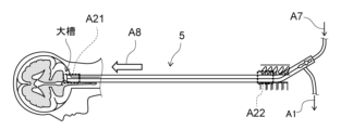
- the brain disease treatment system using the brain disease treatment device 5 includes a spinal subarachnoid space catheter system 2, a pump system 3, and an oxygenation mechanism 4. .
- the brain disease treatment device 5 is used in the spinal subarachnoid catheter system 2.
- the brain disease treatment device 5 is inserted into the subarachnoid space from near the lumbar vertebrae in a lateral position and delivered to the vicinity of the cisterna magna, and a high oxygen solution (oxygenated cerebrospinal fluid in this embodiment) is delivered to the distal end. is injected into the cerebrospinal fluid (CSF) present in the subarachnoid space, and the cerebrospinal fluid present in the subarachnoid space is aspirated at the proximal end and drained out of the patient's body.
- the high oxygen solution of this embodiment is an example of the "liquid" of the present invention.
- the pump system 3 includes a discharge pump 31 and an injection pump 32. As shown by arrow A1, arrow A2, and arrow A3 shown in FIG.
- the flow rate when aspirating (that is, discharging) cerebrospinal fluid from the subarachnoid space is, for example, approximately 0.1 mL/min or more and 500 mL/min or less.
- the suction flow rate (that is, the discharge flow rate) is not limited to 0.1 mL/min or more and 500 mL/min or less.
- the infusion pump 32 sucks the high oxygen solution supplied from the oxygenation mechanism 4 and injects it into the cerebrospinal fluid via the brain disease treatment device 5.
- the flow rate when injecting the high oxygen solution into the cerebrospinal fluid is, for example, approximately 0.1 mL/min or more and 500 mL/min or less. However, the injection rate is not limited to 0.1 mL/min or more and 500 mL/min or less.
- injection and drainage may be performed by a method in which a pump is used to perform natural injection, or a method in which injection and drainage are performed using potential energy, such as an intravenous drip, without using a pump.
- the oxygenation mechanism 4 includes an oxygen bubbling 41, an artificial cerebrospinal fluid bag 42, and an oxygen supply source 43.
- the artificial cerebrospinal fluid bag 42 stores artificial cerebrospinal fluid (aCSF) and supplies the artificial cerebrospinal fluid to the oxygen bubbling 41 as indicated by arrow A4 in FIG.
- the artificial cerebrospinal fluid can be composed of a liquid containing, for example, lactated Ringer's solution.
- the oxygen supply source 43 supplies oxygen to the oxygen bubbling 41 as indicated by arrow A5 shown in FIG.
- the oxygen bubbling 41 mixes cerebrospinal fluid supplied from the discharge pump 31, artificial cerebrospinal fluid supplied from the artificial cerebrospinal fluid bag 42, and oxygen supplied from the oxygen supply source 43 to generate oxygen.
- Oxygenated cerebrospinal fluid is produced, and the oxygenated cerebrospinal fluid is supplied to the injection pump 32 as a high oxygen solution as indicated by arrow A6 in FIG.
- the oxygenation mechanism 4 uses oxygen bubbling 41, but the hollow fibers are immersed in cerebrospinal fluid, oxygen is passed through the hollow fibers, and the cerebrospinal fluid is absorbed through the pores on the surface of the hollow fibers.
- the liquid may be oxygenated.
- the brain disease treatment device 5 is inserted into the subarachnoid space from near the lumbar vertebrae of the patient.
- the tip of the brain disease treatment device 5 is delivered near the patient's cisterna magna.
- the high oxygen solution is sent to the distal end of the brain disease treatment device 5 and injected into the cerebrospinal fluid present in the subarachnoid space.
- the arrow A1 shown in FIG. 2 corresponds to the arrow A1 shown in FIG.
- Arrow A7 shown in FIG. 2 corresponds to arrow A7 shown in FIG.
- FIG. 3 is a plan view showing the distal end portion of the brain disease treatment device according to this embodiment.
- FIG. 4 is a plan view showing the proximal end of the brain disease treatment device according to this embodiment.
- FIG. 5 is a sectional view taken along the cut plane A23-A23 shown in FIG. Note that FIG. 3 is an enlarged view showing the brain disease treatment device 5 in the area A21 shown in FIG. 2 in an enlarged manner.
- FIG. 4 is an enlarged view showing the brain disease treatment device 5 in area A22 shown in FIG. 2. As shown in FIG.
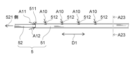
- the brain disease treatment device 5 includes a first tube 51 and a second tube 52.
- the first tube 51 has a plurality of holes 512 on the side surface thereof.
- the hole 512 communicates the inner lumen 513 (see FIG. 5) of the first tube 51 with the outside of the first tube 51.
- the distal end 511 of the first tube 51 is open and placed in the subarachnoid space near the lumbar vertebrae. As shown by arrows A10, A11, and A12 shown in FIG. 511 and the plurality of holes 512 into the space 53 (see FIG. 5) between the inner lumen 513 of the first tube 51 and the outside of the second tube 52. Note that, as described above with reference to FIG.
- the force for sucking the cerebrospinal fluid is provided by the discharge pump 31. Then, as indicated by the arrow A1 shown in FIGS. 1 and 2, the first tube 51 drains the cerebrospinal fluid out of the patient's body through the space 53.
- the outer diameter of the second tube 52 is smaller than the inner diameter of the first tube 51.
- the second tube 52 is positionable in the lumen 513 of the first tube 51 .
- the second pipe 52 is not connected to the first pipe 51 and is movable in the lumen 513 of the first pipe 51 along the longitudinal direction D1 (see FIG. 4) of the first pipe 51. It is. Since the tip 511 of the first tube 51 is open, the tip 521 of the second tube 52 can pass through the opening of the tip 511 of the first tube 51, as shown in FIG. be.
- the tip 521 of the second tube 52 can be exposed from the tip 511 of the first tube 51 in the longitudinal direction D1 of the first tube 51.
- the distance in the longitudinal direction D1 between the tip 511 of the first tube 51 and the tip 521 of the second tube 52 exposed from the tip 511 of the first tube 51 can be adjusted to a predetermined distance. be.
- the "predetermined distance” includes, for example, approximately 0 cm or more and 30 cm or less. If the distance between the tip 521 of the second tube 52 and the tip 511 of the first tube 51 is too close, the high oxygen solution injected into the cerebrospinal fluid through the second tube 52 will be sucked out by the first tube. This reduces the effectiveness of high oxygen solution injection.
- the maximum adjustable distance between the distal end 511 of the first tube 51 and the distal end 521 of the second tube 52 be 10 cm or more. Also, a position several centimeters cranial from the lumbar puncture site, which is assumed to be the placement position of the tip 511 of the first tube 51, from the cisterna magna, which is assumed to be the placement position of the tip 521 of the second tube 52. The distance to this point is thought to be 30cm to 50cm.
- the brain disease treatment device 5 can , is more preferable because it can accommodate various procedure policies that take into consideration the risks and the like during delivery of the second tube 52. For example, this includes one in which the distance between the distal end 511 of the first tube 51 and the distal end 521 of the second tube 52 can be adjusted from 0 cm to 30 cm. Moreover, if the maximum adjustable distance is 50 cm, the brain disease treatment device 5 is considered to be applicable to most patients. However, the "predetermined distance" in this specification is not limited to 0 cm or more and 30 cm or less.
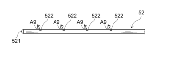
- the second tube 52 has a plurality of holes 522 on the side surface of the second tube 52.
- the hole 522 communicates the inner lumen 523 (see FIG. 5) of the second tube 52 with the outside of the second tube 52.
- the distal end 521 of the second tube 52 is closed, passes through the opening of the distal end 511 of the first tube 51, and is disposed near the cisterna magna.
- the second tube 52 is inserted into the subarachnoid space of the patient and directs the high oxygen solution through the lumen 523 and the plurality of holes 522 into the vicinity of the cisterna magna. injected into the cerebrospinal fluid present in the subarachnoid space. Note that, as discussed above with respect to FIG. 1, the force for injecting the hyperoxic solution into the cerebrospinal fluid is provided by the infusion pump 32.
- the second tube 52 diffuses the oxygen-rich solution in all directions through the plurality of holes 522 around the injection point into the large space of the cisterna magna. It is thought that it is possible to do so.
- the configuration in which the distal end portion 521 of the second tube 52 is closed has been described, but the distal end portion 521 of the second tube 52 may have an open configuration. For example, if the space into which the high-oxygen solution is injected is not large, and if the tip 521 of the second tube 52 is configured to be open, the second tube 52 will inject the high-oxygen solution toward the front. High oxygen solution can be delivered deeper.
- the cross-sectional area of the space 53 between the outside of the second tube 52 and the inside of the first tube 51 is ICP (ICP).
- ICP intraluminal pressure
- the "predetermined ratio” is preferably about 0.5 times or more and 2 times or less, for example. However, the "predetermined ratio" in this specification is not limited to 0.5 times or more and 2 times or less.
- a first specific example of a treatment method using the brain disease treatment device 5 of this embodiment will be described below with reference to FIGS. 1 and 4.
- a puncture needle of a puncture device (not shown) is inserted into the subarachnoid space through the patient's lumbar vertebrae.
- the first tube 51 is inserted into the inner lumen of the puncture needle of the puncture device and inserted into the subarachnoid space, and the distal end 511 of the first tube 51 is placed at a position several centimeters cephalad from the lumbar puncture site. Detained at.
- the puncture needle is removed from the lumbar vertebrae, and the proximal end of the first tube 51 is inserted into the first insertion port 612 of the treatment device connector 6 and fixed.
- the second tube 52 is inserted into the inner cavity of the first tube 51 by inserting the second tube 52 into the second insertion port 622 of the therapeutic device connector 6, and the second tube 52 is inserted into the inner cavity of the first tube 51.
- the distal end 521 of is delivered cranially into the subarachnoid space and placed near the cisterna magna.
- the infusion pump 32 connected to the proximal end of the lumen of the second tube 52 is activated to infuse the high oxygen solution into the cerebrospinal cord in the cisterna magna of the subarachnoid space through the hole 522 of the second tube 52.
- the evacuation pump 31 connected to the proximal end of the lumen of the first tube 51 is activated, and the distal end of the first tube 51 is activated. Through opening 511 and hole 512, approximately the same amount of cerebrospinal fluid as the amount of hyperoxic solution injected is drained out of the body.
- a puncture needle of a puncture device (not shown) is inserted into the subarachnoid space through the patient's lumbar vertebrae.
- a guide wire (not shown) is inserted into the lumen of the puncture needle of the puncture device and inserted into the subarachnoid space.
- only the puncture device is removed from the lumbar vertebrae while the guide wire remains inserted into the subarachnoid space.
- only the guide wire is inserted from the lumbar vertebrae to the subarachnoid space.
- a guide wire is inserted into the lumen of the first tube 51, the first tube 51 is advanced along the guide wire, and the first tube 51 is inserted into the subarachnoid space.
- only the guide wire is removed while the first tube 51 remains inserted into the subarachnoid space from the lumbar vertebrae. In this case, only the first tube 51 is inserted into the subarachnoid space from the lumbar vertebrae.
- the second tube 52 is inserted into the lumen of the first tube 51, and the distal end 521 of the second tube 52 is delivered toward the cranial side of the subarachnoid space and placed near the cisterna magna. . Then, the infusion pump 32 connected to the proximal end of the lumen of the second tube 52 is activated to infuse the high oxygen solution into the cerebrospinal cord in the cisterna magna of the subarachnoid space through the hole 522 of the second tube 52.
- the evacuation pump 31 connected to the proximal end of the lumen of the first tube 51 is activated, and the distal end of the first tube 51 is activated.
- the distal end of the first tube 51 is activated.
- approximately the same amount of cerebrospinal fluid as the amount of hyperoxic solution injected is drained out of the body. This increases the oxygen concentration in the cerebrospinal fluid and supplies oxygen to areas of the brain that lack oxygen, thereby preventing or reducing the progression of cerebral infarction.
- the first tube 51 and the second tube 52 are removed from the patient's lumbar vertebrae.
- the first tube 51 and the second tube 52 are inserted into the subarachnoid space from the patient's lumbar vertebrae.
- the first tube 51 and the second tube 52 may be inserted into the subarachnoid space from the head.
- two pumps, the infusion pump 32 and the discharge pump 31 are used to inject a high oxygen solution and discharge the cerebrospinal fluid.
- the patient may then inject a hyperoxic solution and drain the cerebrospinal fluid.
- cerebrospinal fluid discharged from the patient's subarachnoid space may be oxygenated by the oxygenation mechanism 4 and injected into the patient's subarachnoid space.
- the brain disease treatment device 5 according to the present embodiment, after the first tube 51 and the second tube 52 are inserted into the subarachnoid space from one puncture site near the lumbar vertebrae, the second tube 52 is inserted into the subarachnoid space. , can move through the lumen 513 of the first tube 51 and can be exposed from the distal end 511 of the first tube 51 in the longitudinal direction D1. As a result, the brain disease treatment device 5 according to the present embodiment can inject the high oxygen solution into the cerebrospinal fluid and discharge the cerebrospinal fluid at one puncture site, and can inject the high oxygen solution into the brain.
- the injection position of the second tube 52 for injecting the spinal fluid and the discharge position of the first tube 51 for draining the cerebrospinal fluid out of the patient's body can be adjusted independently.
- a cerebral infarction it becomes possible to adopt an arrangement that can efficiently deliver a high-oxygen solution depending on the patient's body shape and the area where the cerebral infarction occurs, thereby reducing the amount of oxygen that occurs in brain cells. Damage can be suppressed.
- a cerebral infarction it becomes possible to arrange a tube appropriately according to the location of the onset, and it is possible to efficiently administer a high oxygen solution and suppress damage caused to brain cells.
- the brain disease treatment device 5 there is a gap between the distal end 511 of the first tube 51 and the distal end 521 of the second tube 52 exposed from the distal end 511 of the first tube 51.
- the distance in the longitudinal direction D1 can be adjusted to a predetermined distance or more. Therefore, the discharge position of the first tube 51 and the injection position of the second tube 52 can be separated by a predetermined distance or more in the longitudinal direction D1. Therefore, it is possible to prevent the high oxygen solution injected into the cerebrospinal fluid through the second tube 52 from being immediately sucked into the first tube 51 and discharged from the patient's body. Thereby, it is possible to efficiently discharge the cerebrospinal fluid and inject the high oxygen solution into the cerebrospinal fluid.
- the cross-sectional area of the space 53 is within a predetermined ratio to the cross-sectional area of the lumen 523 of the second tube 52, so that the cerebrospinal fluid is Cerebrospinal fluid can be efficiently drained and injected while maintaining a balance between draining and injecting fluid into the cerebrospinal fluid.
- FIG. 6 is a perspective view illustrating a specific example of the first tube of this embodiment.
- FIG. 7 is a plan view showing the first tube of this specific example. Note that FIG. 7 schematically shows a state in which each hole 512 that appears when the first tube 51 is rotated in the circumferential direction about the axis A31 of the first tube 51 is projected onto a predetermined plane.
- the plurality of holes 512 are arranged in a spiral shape on the side surface of the first tube 51. Specifically, as shown in FIG. 7, the plurality of holes 512 are provided at different positions in the circumferential direction of the first pipe 51 and spaced apart from each other by substantially equal intervals L1. ing. Further, the plurality of holes 512 are provided at mutually different positions in the longitudinal direction D1 (that is, in the direction of the axis A31) and at positions separated from each other by substantially equal intervals L2. Note that the direction of the spiral may be either right-handed or left-handed toward the tip.
- the plurality of holes 512 are arranged spirally on the side of the first tube 51, when the first tube 51 is inserted into the subarachnoid space and aspirates cerebrospinal fluid, the patient's Even if tissue in the living body sticks to any of the plurality of holes 512, it is possible to prevent all of the plurality of holes 512 from being blocked by the tissue. This can prevent the first tube 51 from being unable to suction and drain the cerebrospinal fluid.
- FIG. 6 and FIG. 7 illustrate the case where the plurality of holes 512 are arranged in a spiral shape
- the arrangement form of the plurality of holes 512 is not limited to the spiral shape.
- the plurality of holes 512 may be randomly arranged in the longitudinal direction D1 and the circumferential direction.
- the plurality of holes 512 are located at the same position in the circumferential direction of the first tube 51, but at different positions in the longitudinal direction D1, and are spaced apart from each other at substantially equal intervals L2. It may be provided in a different position.
- the plurality of holes 512 may be provided at the same position in the longitudinal direction D1, at different positions in the circumferential direction of the first tube 51, and at substantially equal intervals L1 apart from each other. . Even in such a case, as in the case where the plurality of holes 512 are arranged spirally, it is possible to prevent all of the plurality of holes 512 from being blocked by tissue, and the first tube 51 This can prevent the inability to aspirate and drain cerebrospinal fluid.
- FIG. 8 is a cross-sectional view showing the connector for a treatment device according to this embodiment.
- the treatment device connector 6 has a first holding part 61 , a second holding part 62 , and an outlet part 63 .
- the first holding part 61 has a first contact part 611.
- the inner diameter of the first close contact portion 611 is equal to or less than the outer diameter of the first tube 51 .
- the first holding portion 61 holds the first tube 51 inserted from the first insertion port 612 in the direction of arrow A13 shown in FIG. 8 at the first close contact portion 611.
- the first contact portion 611 has a first tapered portion 613.
- the first tapered portion 613 is a portion whose inner diameter gradually decreases in the direction in which the first tube 51 is inserted from the first insertion port 612 (ie, in the direction of arrow A13).
- the first tube 51 is reliably brought into close contact with the first tapered portion 613 of the first close contact portion 611 in a fluid-tight manner. Thereby, the first tube 51 can be fixed inside the first holding part 61.
- the second holding part 62 has a second contact part 621.
- the inner diameter of the second close contact portion 621 is equal to or less than the outer diameter of the second tube 52 .
- the second holding portion 62 holds the second tube 52 inserted from the second insertion port 622 in the direction of arrow A14 shown in FIG. 8 at the second close contact portion 621.
- the second contact portion 621 has a second tapered portion 623.
- the second tapered portion 623 is a portion whose inner diameter gradually decreases in the direction in which the second tube 52 is inserted from the second insertion port 622 (ie, in the direction of arrow A14). Since the second close contact portion 621 has the second tapered portion 623, the second pipe 52 is reliably brought into close contact with the second tapered portion 623 of the second close contact portion 621 in a liquid-tight manner.
- the outlet part 63 is sandwiched between the first holding part 61 and the second holding part 62 and is fixed to the first holding part 61 and the second holding part 62.
- the first holding part 61, the second holding part 62, and the outlet part 63 may be formed integrally, or may be formed separately and joined to each other.
- the outlet portion 63 has a flow path 631 through which the cerebrospinal fluid passing through the space 53 flows.
- the cerebrospinal fluid passing through space 53 is cerebrospinal fluid that has been aspirated into space 53 through the opening in tip 511 and the plurality of holes 512.
- the cerebrospinal fluid that has flowed through the channel 631 is discharged from an outlet 632 provided in the outlet section 63. Note that the arrow A1 shown in FIG. 8 corresponds to the arrow A1 shown in FIGS. 1 and 2.
- the second The close contact portion 621 exists inside the first close contact portion 611 .
- the second tube 52 inserted from the second insertion port 622 can be inserted into the lumen 513 of the first tube 51 fixed to the first holding part 61, It is possible to penetrate the first tube 51.
- the high oxygen solution is injected into the cerebrospinal fluid present in the subarachnoid space near the cisterna magna through the lumen 523 of the second tube 52.
- arrow A7 shown in FIG. 8 corresponds to arrow A7 shown in FIGS. 1 and 2.
- the arrow A1 shown in FIG. is discharged from the outlet 632.
- the first tube 51 of the brain disease treatment device 5 is inserted into the patient's body through a spinal needle punctured into the patient's body, and the spinal needle is removed.
- the first holding part 61 can hold the first tube 51 inserted through the first insertion port 612 at the first close contact part 611 .
- the second holding portion 62 can hold the second tube 52 inserted through the second insertion port 622 at the second close contact portion 621 .
- the second close contact portion 621 exists inside the first close contact portion 611.
- the second tube 52 can be easily placed through the second close contact portion 621 without having to be aligned with the inner lumen 513 of the first tube 51. can be moved longitudinally (axially).
- the outlet portion 63 has a channel 631 through which the cerebrospinal fluid passing through the space 53 flows, and also has an outlet 632 of the channel 631.
- the therapeutic device connector 6 according to the present embodiment is configured such that, after the spinal needle is removed, the first tube 51 It is said that it can be attached to the pipe 51.
- the second tube 52 can be easily placed in the inner cavity 513 of the first tube 51, and the second tube 52 can be easily placed in the inner cavity 513 of the first tube 51.
- the inner lumen 513 of the tube 51 of No. 1 can be easily moved in the longitudinal direction (axial direction).
- the therapeutic device connector 6 is configured to insert the first tube 51 into the patient's body after the spinal needle is removed.
- the cerebrospinal fluid discharged from the proximal end 514 of the first tube 51 can pass through the channel 631 of the outlet section 63 and be discharged out of the body.
- the first tube 51 is reliably and fluid-tightly adhered to the first tapered portion 613 of the first contact portion 611.
- the second pipe 52 is in close contact with the second tapered portion 623 of the second close contact portion 621 in a liquid-tight manner. Therefore, due to the negative pressure generated when the first tube 51 aspirates cerebrospinal fluid and discharges it out of the patient's body, the gap between the first tube 51 and the first contact portion 611 and between the second tube 52 and It is possible to prevent a gap from forming between the second contact portion 621 and the second contact portion 621 .
- the space between the first tube 51 and the first contact portion 611 and between the second tube 52 and the second It is possible to suppress air from entering the inside of the first tube 51 from between the close contact portion 621 and a decrease in the efficiency of draining the cerebrospinal fluid.
- the connector fixed to the patient's body surface by the treatment device connector fixing tool 7 affixed to an appropriate location on the patient's body surface is the treatment device connector 6 described above with reference to FIG.
- the treatment device connected to the treatment device connector 6 is the brain disease treatment device 5 described above with reference to FIGS. 1 to 7. Therefore, descriptions of the connector fixed to the patient's body surface by the treatment device connector fixture 7 and the treatment device connected to the treatment device connector 6 will be omitted as appropriate, and the following will focus on the treatment device connector fixture 7.
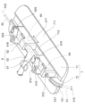
- FIG. 9 is a perspective view showing a specific example of the treatment device connector fixture according to the present embodiment and the treatment device connector according to the present embodiment.
- the treatment device connector fixture 7 includes a fixture main body 71 and a tube holding part 72.
- the fixture main body 71 has a body surface attachment portion 711 and a connector attachment portion 712. As shown in FIG. 9, the body surface attachment portion 711 has a plate shape and is attached to the patient's body surface.
- the connector attachment portion 712 attaches the treatment device connector 6 to the fixture body 71.
- the connector attachment portion 712 is a groove formed in the fixture main body 71 along the longitudinal direction D1 (see FIG. 4).
- a magnet 64 is attached to the lower surface of each of the first holding part 61 and the second holding part 62.
- the lower surface of each of the first holding part 61 and the second holding part 62 is a surface facing the connector attachment part 712.
- the treatment device connector 6 is attached to the connector attachment portion 712 by attracting the magnet 64 to the connector attachment portion 712 .
- an arrow A17 shown in FIG. The second tube 52 held by the second holding part 62 can be adjusted along the direction of the axis A32.
- the tube holding part 72 is fixed to the distal end of the fixture body 71 and can hold the first tube 51.
- a groove having substantially the same diameter as the outer diameter of the first tube 51 is formed in a portion where the tube holding portion 72 holds the first tube 51 .
- the tube holding portion 72 has a curved portion 721 provided at a portion with which the first tube 51 comes into contact. Thereby, the tube holding part 72 can suppress the first tube 51 from kinking (breaking, etc.) in the vicinity of the puncture site 515.
- the connector attachment portion 712 positions the attachment position of the treatment device connector 6 on the axis A31 of the first tube 51 held by the first holding portion 61. and along the direction of the axis A32 of the second tube 52 held by the second holding part 62. Therefore, regardless of the length of the first tube 51 inserted into the subarachnoid space, the therapeutic device connector fixing tool 7 can be used at the position where the first tube 51 is inserted into the subarachnoid space (i.e., the puncture point). 515) to the patient's body surface at any position within a certain range along the direction of the axis A31 of the first tube 51. This can prevent the first tube 51 from kinking or falling off.
- the first holding part 61 has a first pinching part 614.
- the first pinching portion 614 is rotatably supported by a first support shaft 615 provided on the first holding portion 61.
- the first pinching part 614 pinches and fixes the first tube 51 by rotating in the closing direction with respect to the first holding part 61.
- the second holding portion 62 has a second sandwiching portion 624 .
- the second pinching portion 624 is rotatably supported by a second support shaft 625 provided on the second holding portion 62.
- the second pinching part 624 pinches and fixes the second tube 52 by rotating in the closing direction with respect to the second holding part 62 .
- the treatment device connector 6 can fix the injection position of the high oxygen solution through the second tube 52 and the discharge position (i.e., suction position) of the cerebrospinal fluid through the first tube 51 after adjusting them. can.
Abstract
This therapeutic device for brain diseases (5) is provided with a first tube (51) and a second tube (52) that has an outer diameter smaller than the inner diameter of the first tube (51), can be placed in an inner cavity of the first tube (51) and can move in the inner cavity of the first tube (51). The first tube (51) is inserted into a subarachrnoid cavity in a patient, and discharges a cerebrospinal fluid present in the subarachrnoid cavity to the outside of the body of the patient through a space formed between the inner cavity of the first tube (51) and the outside of the second tube (52). The second tube (52) is inserted into the subarachrnoid cavity, and injects a liquid into the cerebrospinal fluid present in the subarachrnoid cavity through the inner cavity of the second tube (52). An end part (521) of the second tube (52) can be exposed from an end part (511) of the first tube (51) in the length direction (D1) of the first tube (51).
Description
本発明は、脳疾患の治療に用いられる脳疾患治療デバイス、治療デバイスに接続される治療デバイス用コネクタ、および治療デバイス用コネクタを患者の体表に固定する治療デバイス用コネクタ固定具に関する。
The present invention relates to a brain disease treatment device used for the treatment of brain diseases, a treatment device connector connected to the treatment device, and a treatment device connector fixture for fixing the treatment device connector to the body surface of a patient.
脳疾患として例えば脳梗塞が発症すると、脳細胞に酸素を供給する血流が遮断され、脳細胞にダメージが発生するおそれがある。したがって、脳梗塞が発症した場合には、血流の早期再灌流が必要である。しかし、現在臨床で行われている高いエビデンスレベルの超急性期治療(例えば組織プラスミノーゲンアクチベーター(t-PA)投与や機械的血栓回収療法(MT)など)を受けるための条件が満たされる患者の割合が低い。そのため、多くの患者は、保存療法しか選択できていない。
When a cerebral infarction occurs as a brain disease, for example, the blood flow that supplies oxygen to brain cells is blocked, potentially causing damage to the brain cells. Therefore, when cerebral infarction occurs, early reperfusion of blood flow is necessary. However, the conditions for receiving hyperacute treatment (e.g., tissue plasminogen activator (t-PA) administration, mechanical thrombectomy therapy (MT), etc.) that are currently performed in clinical practice and have a high level of evidence are met. A low proportion of patients. Therefore, conservative treatment is the only option for many patients.
脳梗塞の治療の1つとして、酸素化した脳脊髄液などの高酸素溶液を患者の髄腔内に注入し、酸素が欠乏している脳細胞に酸素を直接供給することが提案されている。ここで、特許文献1には、早期脳卒中治療を提供するための方法およびシステムが開示されている。特許文献1に記載された方法およびシステムでは、栄養エマルジョンは、先端部が大槽の付近に挿入された導管を介して大槽から回収される。また、酸素化栄養素エマルジョンは、保持具を介して頭蓋骨に取り付けられた注入カニューレを通して側脳室へ注入される。
As one treatment for cerebral infarction, it has been proposed to inject a highly oxygenated solution such as oxygenated cerebrospinal fluid into the patient's spinal cavity to directly supply oxygen to oxygen-deficient brain cells. . Here, Patent Document 1 discloses a method and system for providing early stroke treatment. In the method and system described in U.S. Pat. No. 5,601,307, a nutrient emulsion is withdrawn from the cisterna magna via a conduit whose tip is inserted in the vicinity of the cisterna magna. The oxygenated nutrient emulsion is also injected into the lateral ventricle through an infusion cannula attached to the skull via a retainer.
特許文献1に記載された方法およびシステムは、2つの穿刺箇所で高酸素溶液の注入と脳脊髄液の排出とを行う。しかし、患者侵襲を考慮すると、1つの穿刺箇所で高酸素溶液の注入と脳脊髄液の排出とを可能にすることが望ましい。
そこで、1つのカテーテルを1つの穿刺箇所から患者の髄腔内に挿入し、高酸素溶液の注入と脳脊髄液の排出とを行う手段が考えられる。この場合には、高酸素溶液の注入と脳脊髄液の排出との効率を考慮すると、1つのカテーテルを患者の生体内に挿入した後、高酸素溶液の注入位置と脳脊髄液の吸引位置(すなわち排出位置)とをカテーテルの挿入方向(すなわち長手方向)において独立して調整することが望ましい。 The method and system described in U.S. Pat. No. 5,300,301 performs injection of a hyperoxic solution and drainage of cerebrospinal fluid at two puncture sites. However, considering patient invasiveness, it is desirable to be able to inject a hyperoxic solution and drain cerebrospinal fluid at a single puncture site.
Therefore, a possible method is to insert one catheter into the patient's spinal cavity from one puncture site to inject a high oxygen solution and drain cerebrospinal fluid. In this case, considering the efficiency of injecting the high oxygen solution and draining the cerebrospinal fluid, after inserting one catheter into the patient's body, the injection position of the high oxygen solution and the suction position of the cerebrospinal fluid ( In other words, it is desirable to adjust the catheter position (i.e., the ejection position) independently in the insertion direction (i.e., the longitudinal direction) of the catheter.
本発明は、前記事情に鑑みてなされたものであり、1つの穿刺箇所で注入と排出とが可能であり、生体内に挿入した後に注入位置と排出位置とを独立して調整可能である脳疾患治療デバイス、治療デバイスに接続される治療デバイス用コネクタ、および治療デバイス用コネクタを患者の体表に固定する治療デバイス用コネクタ固定具を提供することを目的とする。
The present invention has been made in view of the above-mentioned circumstances, and it is possible to inject and discharge at one puncture site, and the injection and discharge positions can be adjusted independently after being inserted into a living body. It is an object of the present invention to provide a disease treatment device, a treatment device connector connected to the treatment device, and a treatment device connector fixture for fixing the treatment device connector to the body surface of a patient.
前記課題は、第1の管と、外径が前記第1の管の内径よりも小さく、前記第1の管の内腔に配置可能であるとともに前記第1の管の内腔を移動可能な第2の管と、を備え、前記第1の管は、患者のクモ膜下腔に挿入され、前記クモ膜下腔に存在する脳脊髄液を前記第1の管の内腔と前記第2の管の外側との間の空間を通して前記患者の体外に排出し、前記第2の管は、前記クモ膜下腔に挿入され、液体を前記第2の管の内腔を通して前記クモ膜下腔に存在する前記脳脊髄液に注入し、前記第2の管の端部は、前記第1の管の長手方向において前記第1の管の端部から露出可能とされてなることを特徴とする本発明に係る脳疾患治療デバイスにより解決される。
The problem is to provide a first tube having an outer diameter smaller than an inner diameter of the first tube, which can be placed in the inner lumen of the first tube, and which is movable in the inner lumen of the first tube. a second tube, the first tube is inserted into the subarachnoid space of the patient, and the cerebrospinal fluid present in the subarachnoid space is transferred between the lumen of the first tube and the second tube. and the second tube is inserted into the subarachnoid space and directs liquid through the lumen of the second tube into the subarachnoid space. and the end of the second tube is exposed from the end of the first tube in the longitudinal direction of the first tube. This problem is solved by the brain disease treatment device according to the present invention.
本発明に係る脳疾患治療デバイスによれば、第2の管の外径は、第1の管の内径よりも小さい。第2の管は、第1の管の内腔に配置可能であるとともに第1の管の内腔を移動可能である。第1の管は、患者のクモ膜下腔に挿入され、クモ膜下腔に存在する脳脊髄液を第1の管の内腔と第2の管の外側との間の空間を通して患者の体外に排出する。第2の管は、クモ膜下腔に挿入され、液体を第2の管の内腔を通してクモ膜下腔に存在する脳脊髄液に注入する。ここで、第2の管の端部は、第1の管の長手方向において第1の管の端部から露出可能とされている。そのため、第1の管および第2の管が患者のクモ膜下腔に挿入された後、第2の管は、第1の管の内腔を移動することができるとともに、第1の管の端部から露出することができる。これにより、1つの穿刺箇所で、脳脊髄液に対する液体の注入と、脳脊髄液の排出と、が可能であり、液体を脳脊髄液に注入する第2の管の注入位置と、脳脊髄液を患者の体外に排出する第1の管の排出位置と、を独立して調整することができる。
According to the brain disease treatment device according to the present invention, the outer diameter of the second tube is smaller than the inner diameter of the first tube. The second tube is positionable and movable within the lumen of the first tube. The first tube is inserted into the patient's subarachnoid space and directs the cerebrospinal fluid present in the subarachnoid space through the space between the lumen of the first tube and the outside of the second tube to outside the patient's body. to be discharged. A second tube is inserted into the subarachnoid space and injects fluid through the lumen of the second tube into the cerebrospinal fluid present in the subarachnoid space. Here, the end of the second tube can be exposed from the end of the first tube in the longitudinal direction of the first tube. Therefore, after the first tube and the second tube are inserted into the patient's subarachnoid space, the second tube can move within the lumen of the first tube and Can be exposed from the ends. This allows for the injection of fluid into the cerebrospinal fluid and the drainage of the cerebrospinal fluid at one puncture point, and the injection location of the second tube for injecting the fluid into the cerebrospinal fluid and the cerebrospinal fluid. The discharge position of the first tube which discharges the patient's body from the patient's body can be adjusted independently.
本発明に係る脳疾患治療デバイスにおいて、好ましくは、前記第1の管の端部と、前記第1の管の端部から露出した前記第2の管の端部と、の間の前記長手方向の距離が所定距離以上に調整可能であることを特徴とする。
In the brain disease treatment device according to the present invention, preferably, the longitudinal direction between the end of the first tube and the end of the second tube exposed from the end of the first tube is is characterized in that the distance can be adjusted to a predetermined distance or more.
本発明に係る脳疾患治療デバイスによれば、第1の管の端部と、第1の管の端部から露出した第2の管の端部と、の間の長手方向の距離が所定距離以上に調整可能である。そのため、第1の管の排出位置と、第2の管の注入位置と、を長手方向において所定距離以上に離すことができる。そのため、第2の管により脳脊髄液に注入された液体が、すぐに第1の管により吸引され患者の体外に排出されることを抑えることができる。これにより、脳脊髄液の排出と、脳脊髄液に対する液体の注入と、を効率的に行うことができる。
According to the brain disease treatment device according to the present invention, the longitudinal distance between the end of the first tube and the end of the second tube exposed from the end of the first tube is a predetermined distance. It is possible to adjust more than that. Therefore, the discharge position of the first tube and the injection position of the second tube can be separated by a predetermined distance or more in the longitudinal direction. Therefore, it is possible to prevent the fluid injected into the cerebrospinal fluid through the second tube from being immediately sucked into the first tube and discharged from the patient's body. Thereby, it is possible to efficiently discharge the cerebrospinal fluid and inject fluid into the cerebrospinal fluid.
本発明に係る脳疾患治療デバイスにおいて、好ましくは、前記長手方向に対して垂直方向の切断面において、前記第1の管の内腔と前記第2の管の外側との間の空間の断面積は、前記第2の管の内腔の断面積に対して所定比率の範囲内であることを特徴とする。
In the brain disease treatment device according to the present invention, preferably, a cross-sectional area of a space between the inner lumen of the first tube and the outside of the second tube in a cut plane perpendicular to the longitudinal direction. is within a predetermined ratio to the cross-sectional area of the inner lumen of the second tube.
本発明に係る脳疾患治療デバイスによれば、長手方向に対して垂直方向の切断面において、第1の管の内腔と第2の管の外側との間の空間の断面積は、第2の管の内腔の断面積に対して所定比率の範囲内である。これにより、脳脊髄液の排出と、脳脊髄液に対する液体の注入と、の均衡を保ちつつ脳脊髄液の排出および注入を効率的に行うことができる。
According to the brain disease treatment device according to the present invention, the cross-sectional area of the space between the lumen of the first tube and the outside of the second tube in the cut plane in the direction perpendicular to the longitudinal direction is the same as that of the second tube. is within a predetermined ratio to the cross-sectional area of the lumen of the tube. Thereby, the cerebrospinal fluid can be efficiently discharged and injected while maintaining a balance between the discharge of the cerebrospinal fluid and the injection of fluid into the cerebrospinal fluid.
本発明に係る脳疾患治療デバイスにおいて、好ましくは、前記第1の管は、前記第1の管の内腔と前記第1の管の外側とを連通させる複数の孔を前記第1の管の側面に有し、前記複数の孔は、前記第1の管の周方向において互いに異なる位置であって互いに実質的に均等な間隔で離れた位置に設けられたことを特徴とする。
In the brain disease treatment device according to the present invention, preferably, the first tube has a plurality of holes that communicate between the inner lumen of the first tube and the outside of the first tube. The plurality of holes are provided at different positions in the circumferential direction of the first tube and spaced apart from each other at substantially equal intervals.
本発明に係る脳疾患治療デバイスによれば、第1の管は、第1の管の側面に設けられた複数の孔を通して、第1の管の外側から第1の管の内腔に脳脊髄液を吸引し患者の体外に排出する。第1の管の複数の孔は、第1の管の周方向において互いに異なる位置であって互いに実質的に均等な間隔で離れた位置に設けられている。そのため、第1の管がクモ膜下腔に挿入され脳脊髄液を吸引する際に、患者の生体内の組織が複数の孔のいずれかに吸い付いた場合でも、複数の孔のすべてが組織により塞がれることを抑えることができる。これにより、第1の管が脳脊髄液を吸引できず排出できなくなることを抑えることができる。
According to the brain disease treatment device according to the present invention, the first tube connects the cerebrospinal cord from the outside of the first tube to the inner lumen of the first tube through the plurality of holes provided on the side surface of the first tube. Aspirate the fluid and drain it out of the patient's body. The plurality of holes in the first tube are provided at different positions in the circumferential direction of the first tube and spaced apart from each other at substantially equal intervals. Therefore, when the first tube is inserted into the subarachnoid space to aspirate cerebrospinal fluid, even if the tissue in the patient's body sticks to one of the multiple holes, all of the multiple holes are covered with tissue. It is possible to prevent blockage due to This can prevent the first tube from being unable to suction and drain the cerebrospinal fluid.
本発明に係る脳疾患治療デバイスにおいて、好ましくは、前記複数の孔は、前記長手方向において互いに異なる位置であって互いに実質的に均等な間隔で離れた位置に設けられたことを特徴とする。
In the brain disease treatment device according to the present invention, preferably, the plurality of holes are provided at different positions in the longitudinal direction and spaced apart from each other at substantially equal intervals.
本発明に係る脳疾患治療デバイスによれば、第1の管の複数の孔は、第1の管の周方向および長手方向において互いに異なる位置であって互いに実質的に均等な間隔で離れた位置に設けられる。そのため、複数の孔は、第1の管の側面において螺旋状に配置される。そのため、第1の管がクモ膜下腔に挿入され脳脊髄液を吸引する際に、患者の生体内の組織が複数の孔のいずれかに吸い付いた場合でも、複数の孔のすべてが組織により塞がれることをより一層抑えることができる。これにより、第1の管が脳脊髄液を吸引できず排出できなくなることをより一層抑えることができる。
According to the brain disease treatment device according to the present invention, the plurality of holes of the first tube are located at different positions in the circumferential direction and longitudinal direction of the first tube and are spaced apart from each other at substantially equal intervals. established in The plurality of holes are therefore arranged in a helical manner on the side of the first tube. Therefore, when the first tube is inserted into the subarachnoid space to aspirate cerebrospinal fluid, even if the tissue in the patient's body sticks to one of the multiple holes, all of the multiple holes are covered with tissue. It is possible to further suppress the occurrence of blockage. Thereby, it is possible to further prevent the first tube from being unable to suction and drain the cerebrospinal fluid.
本発明に係る脳疾患治療デバイスにおいて、好ましくは、前記液体は、高酸素溶液であることを特徴する。
The brain disease treatment device according to the present invention is preferably characterized in that the liquid is a high oxygen solution.
本発明に係る脳疾患治療デバイスによれば、1つの穿刺箇所で、脳脊髄液に対する高酸素溶液の注入と、脳脊髄液の排出と、が可能であり、高酸素溶液を脳脊髄液に注入する第2の管の注入位置と、脳脊髄液を患者の体外に排出する第1の管の排出位置と、を独立して調整することができる。これにより、脳梗塞が発症した場合において、患者の体型や脳梗塞が発症した部位に応じて、効率的に高酸素溶液を届けることができる配置を取ることが可能となるため、脳細胞に生ずるダメージを抑えることができる。また、脳梗塞が発症した場合において、その発症場所に合わせた適切な管の配置が可能となり、効率的に高酸素溶液を投与して脳細胞に生ずるダメージを抑えることができる。
According to the brain disease treatment device according to the present invention, it is possible to inject a high oxygen solution into the cerebrospinal fluid and to discharge the cerebrospinal fluid at one puncture site, and the high oxygen solution can be injected into the cerebrospinal fluid. The injection position of the second tube for draining the cerebrospinal fluid and the discharge position of the first tube for draining the cerebrospinal fluid out of the patient's body can be adjusted independently. As a result, in the event of a cerebral infarction, it becomes possible to adopt an arrangement that can efficiently deliver a high-oxygen solution depending on the patient's body shape and the area where the cerebral infarction occurs, thereby reducing the amount of oxygen that occurs in brain cells. Damage can be suppressed. Furthermore, when a cerebral infarction occurs, it becomes possible to arrange a tube appropriately according to the location of the onset, and it is possible to efficiently administer a high oxygen solution and suppress damage caused to brain cells.
前記課題は、第1の管と、外径が前記第1の管の内径よりも小さく、前記第1の管の内腔に配置可能であるとともに前記第1の管の内腔を移動可能な第2の管と、を有し、前記第1の管は、患者の生体管腔に挿入され、前記生体管腔に存在する液体を前記第1の管の内腔と前記第2の管の外側との間の空間を通して前記患者の体外に排出し、前記第2の管は、前記生体管腔に挿入され、液体を前記第2の管の内腔を通して前記生体管腔に注入し、前記第1の管と前記第2の管とを有する治療デバイスに接続される治療デバイス用コネクタであって、内径が前記第1の管の外径以下である第1の密着部を有し、第1の挿入口から挿入された前記第1の管を前記第1の密着部において保持する第1の保持部と、内径が前記第2の管の外径以下である第2の密着部を有し、第2の挿入口から挿入された前記第2の管を前記第2の密着部において保持する第2の保持部と、前記第1の管の内腔と前記第2の管の外側との間の空間を通過する液体が流れる流路を有するとともに前記流路の出口を有する出口部と、を備え、前記第1の保持部に保持された前記第1の管および前記第2の保持部に保持された前記第2の管のいずれかの軸方向に沿ってみたとき、前記第2の密着部は、前記第1の密着部の内側に存在することを特徴とする本発明に係る治療デバイス用コネクタにより解決される。
The problem is to provide a first tube having an outer diameter smaller than an inner diameter of the first tube, which can be placed in the inner lumen of the first tube, and which is movable in the inner lumen of the first tube. a second tube, the first tube is inserted into a biological lumen of a patient, and the liquid present in the biological lumen is transferred between the lumen of the first tube and the second tube. the second tube is inserted into the body lumen, injecting a liquid into the body lumen through the lumen of the second tube; A connector for a treatment device connected to a treatment device having a first tube and the second tube, the connector having a first close contact portion having an inner diameter equal to or less than an outer diameter of the first tube; a first holding part that holds the first tube inserted through the first insertion port in the first tight fitting part; and a second tight fitting part having an inner diameter equal to or less than an outer diameter of the second tube. a second holding portion that holds the second tube inserted from the second insertion port in the second close contact portion; and an inner lumen of the first tube and an outside of the second tube. an outlet section having a flow path through which liquid passes through a space between the tubes and an outlet of the flow path, the first tube held by the first holding section and the second holding section; According to the present invention, the second close contact portion is located inside the first close contact portion when viewed along the axial direction of any one of the second tubes held in the second tube. Solved by connectors for therapeutic devices.
本発明に係る治療デバイス用コネクタによれば、第1の保持部は、内径が治療デバイスの第1の管の外径以下である第1の密着部を有し、第1の挿入口から挿入された治療デバイスの第1の管を第1の密着部において保持する。第2の保持部は、内径が治療デバイスの第2の管の外径以下である第2の密着部を有し、第2の挿入口から挿入された治療デバイスの第2の管を第2の密着部において保持する。そのため、例えば患者の生体に穿刺されたスパイナル針を通して治療デバイスの第1の管が患者の生体内に挿入され、スパイナル針が抜去された後、第1の保持部は、第1の挿入口から挿入された治療デバイスの第1の管を第1の密着部において保持することができる。また、第2の保持部は、第2の挿入口から挿入された治療デバイスの第2の管を第2の密着部において保持することができる。ここで、第1の保持部に保持された治療デバイスの第1の管および第2の保持部に保持された治療デバイスの第2の管のいずれかの軸方向に沿ってみたとき、第2の密着部は、第1の密着部の内側に存在する。そのため、治療デバイスの第2の管は、第2の密着部を通して治療デバイスの第1の管の内腔に容易に配置されるとともに治療デバイスの第1の管の内腔を容易に移動することができる。そして、出口部は、治療デバイスの第1の管の内腔と、治療デバイスの第2の管の外側と、の間の空間を通過する液体が流れる流路を有するとともに流路の出口を有する。このように、本発明に係る治療デバイス用コネクタは、例えばスパイナル針を用いて治療デバイスの第1の管が患者の生体内に挿入される場合において、スパイナル針が抜去された後、治療デバイスの第1の管に装着可能とされている。そして、本発明に係る治療デバイス用コネクタは、治療デバイスの第1の管に装着された後、治療デバイスの第2の管を治療デバイスの第1の管の内腔に容易に配置させることができるとともに治療デバイスの第1の管の内腔を容易に移動させることができる。
According to the connector for a treatment device according to the present invention, the first holding portion has a first contact portion whose inner diameter is equal to or less than the outer diameter of the first tube of the treatment device, and the first holding portion is inserted through the first insertion port. The first tube of the treated treatment device is held in the first contact portion. The second holding part has a second close contact part whose inner diameter is less than or equal to the outer diameter of the second tube of the treatment device, and the second holding part has a second contact part whose inner diameter is less than or equal to the outer diameter of the second tube of the treatment device, and the second holding part has a second contact part that has an inner diameter that is less than or equal to the outer diameter of the second tube of the treatment device. Hold at the close contact part. Therefore, for example, after the first tube of the treatment device is inserted into the patient's body through a spinal needle punctured into the patient's body and the spinal needle is removed, the first holding part is inserted into the patient's body from the first insertion port. The inserted first tube of the treatment device can be held in the first abutment. Further, the second holding portion can hold the second tube of the treatment device inserted from the second insertion port in the second close contact portion. Here, when viewed along the axial direction of either the first tube of the treatment device held by the first holding part or the second tube of the treatment device held by the second holding part, the second tube The close contact portion exists inside the first close contact portion. Therefore, the second tube of the treatment device can be easily placed in the lumen of the first tube of the treatment device through the second close contact portion, and can be easily moved through the lumen of the first tube of the treatment device. I can do it. The outlet portion has a flow path through which a liquid passes through the space between the inner lumen of the first tube of the treatment device and the outside of the second tube of the treatment device, and has an outlet of the flow path. . As described above, the connector for a therapeutic device according to the present invention allows the first tube of the therapeutic device to be inserted into a patient's body using a spinal needle, for example, after the spinal needle is removed. It is said that it can be attached to the first tube. Then, after the connector for a treatment device according to the present invention is attached to the first tube of the treatment device, the second tube of the treatment device can be easily placed in the inner lumen of the first tube of the treatment device. and the lumen of the first tube of the treatment device can be easily moved.
本発明に係る治療デバイス用コネクタにおいて、好ましくは、前記第1の管は、前記第1の保持部の内部に固定可能とされ、前記第2の挿入口から挿入された前記第2の管は、前記第1の保持部に固定された前記第1の管の内腔に挿入可能とされ、前記第1の管を貫通可能であり、前記第1の保持部に固定された前記第1の管の基端部から排出された液体が、前記流路を通過することを特徴とする。
In the therapeutic device connector according to the present invention, preferably, the first tube is fixable inside the first holding part, and the second tube inserted from the second insertion port is , capable of being inserted into the inner lumen of the first tube fixed to the first holding part, capable of penetrating the first pipe, and fixed to the first holding part. The liquid discharged from the proximal end of the tube passes through the flow path.
本発明に係る治療デバイス用コネクタによれば、治療デバイスの第1の管は、第1の保持部の内部に固定可能とされている。第2の挿入口から挿入された治療デバイスの第2の管は、第1の保持部に固定された治療デバイスの第1の管の内腔に挿入可能とされ、治療デバイスの第1の管を貫通可能である。そして、第1の保持部に固定された治療デバイスの第1の管の基端部から排出された液体が、出口部の流路を通過する。そのため、本発明に係る治療デバイス用コネクタは、例えばスパイナル針を用いて治療デバイスの第1の管が患者の生体内に挿入される場合において、スパイナル針が抜去された後、治療デバイスの第1の管および第2の管に装着されることで、治療デバイスの第1の管の基端部から排出された液体を出口部の流路を通過させて体外に排出することができる。
According to the connector for a treatment device according to the present invention, the first tube of the treatment device can be fixed inside the first holding part. The second tube of the treatment device inserted from the second insertion port can be inserted into the lumen of the first tube of the treatment device fixed to the first holding part, and the second tube of the treatment device can be penetrated. Then, the liquid discharged from the proximal end of the first tube of the treatment device fixed to the first holding part passes through the flow path of the outlet part. Therefore, in the connector for a therapeutic device according to the present invention, when the first tube of the therapeutic device is inserted into a patient's body using a spinal needle, for example, after the spinal needle is removed, the first tube of the therapeutic device By being attached to the tube and the second tube, the liquid discharged from the proximal end of the first tube of the treatment device can be discharged out of the body through the flow path of the outlet section.
本発明に係る治療デバイス用コネクタにおいて、好ましくは、前記第1の保持部は、前記第1の管を挟み込んで固定する第1の挟み込み部を有し、前記第2の保持部は、前記第2の管を挟み込んで固定する第2の挟み込み部を有することを特徴とする。
In the therapeutic device connector according to the present invention, preferably, the first holding part has a first pinching part that pinches and fixes the first tube, and the second holding part has a first holding part that pinches and fixes the first tube. The second tube is characterized by having a second pinching part that pinches and fixes the second tube.
本発明に係る治療デバイス用コネクタによれば、第1の保持部の第1の挟み込み部は、治療デバイスの第1の管を挟み込んで固定する。第2の保持部の第2の挟み込み部は、治療デバイスの第2の管を挟み込んで固定する。これにより、治療デバイスの第2の管が治療デバイスの第1の管の内腔に配置され治療デバイスの第1の管の内腔を移動した後、本発明に係る治療デバイス用コネクタは、治療デバイスの第1の管および第2の管の位置を固定することができる。これにより、本発明に係る治療デバイス用コネクタは、治療デバイスの第2の管の注入位置と、治療デバイスの第1の管の排出位置と、を調整後に固定することができる。
According to the connector for a treatment device according to the present invention, the first pinching portion of the first holding portion sandwiches and fixes the first tube of the treatment device. The second clamping part of the second holding part clamps and fixes the second tube of the treatment device. Thereby, after the second tube of the treatment device is placed in the lumen of the first tube of the treatment device and moves through the lumen of the first tube of the treatment device, the connector for a treatment device according to the present invention can be used for treatment. The position of the first tube and second tube of the device can be fixed. Thereby, the connector for a treatment device according to the present invention can fix the injection position of the second tube of the treatment device and the discharge position of the first tube of the treatment device after adjustment.
本発明に係る治療デバイス用コネクタにおいて、好ましくは、前記第1の密着部は、前記第1の管が前記第1の挿入口から挿入される方向に向かって内径が次第に小さくなる部分を有し、前記第2の密着部は、前記第2の管が前記第2の挿入口から挿入される方向に向かって内径が次第に小さくなる部分を有することを特徴とする。
In the connector for a therapeutic device according to the present invention, preferably, the first close contact portion has a portion whose inner diameter gradually decreases in the direction in which the first tube is inserted from the first insertion port. , the second close contact portion has a portion whose inner diameter gradually decreases in the direction in which the second tube is inserted from the second insertion port.
本発明に係る治療デバイス用コネクタによれば、第1の密着部は、治療デバイスの第1の管が第1の挿入口から挿入される方向に向かって内径が次第に小さくなる部分を有する。そのため、治療デバイスの第1の管は、第1の密着部において内径が次第に小さくなる部分に確実に密着する。また、第2の密着部は、治療デバイスの第2の管が第2の挿入口から挿入される方向に向かって内径が次第に小さくなる部分を有する。そのため、治療デバイスの第2の管は、第2の密着部において内径が次第に小さくなる部分に確実に密着する。そのため、治療デバイスの第1の管が生体管腔に存在する液体を吸引し患者の体外に排出する際に生ずる陰圧によって、治療デバイスの第1の管と第1の密着部との間、および治療デバイスの第2の管と第2密着部との間に、隙間が生ずることを抑えることができる。これにより、治療デバイスの第1の管が生体管腔に存在する液体を吸引し患者の体外に排出する際に、治療デバイスの第1の管と第1の密着部との間、および治療デバイスの第2の管と第2密着部との間から空気が治療デバイスの第1の管の内部に進入することを抑え、液体の排出の効率が低下することを抑えることができる。
According to the connector for a treatment device according to the present invention, the first close contact portion has a portion whose inner diameter gradually decreases in the direction in which the first tube of the treatment device is inserted from the first insertion port. Therefore, the first tube of the treatment device reliably comes into close contact with the portion where the inner diameter gradually decreases in the first contact portion. Further, the second close contact portion has a portion whose inner diameter gradually decreases in the direction in which the second tube of the treatment device is inserted from the second insertion port. Therefore, the second tube of the treatment device reliably comes into close contact with the portion where the inner diameter gradually decreases in the second close contact portion. Therefore, due to the negative pressure generated when the first tube of the treatment device aspirates the liquid present in the living body lumen and discharges it out of the patient's body, the gap between the first tube of the treatment device and the first contact portion is reduced. Also, it is possible to suppress the formation of a gap between the second tube and the second close contact portion of the treatment device. As a result, when the first tube of the treatment device aspirates the liquid present in the biological lumen and discharges it out of the patient's body, there is a gap between the first tube of the treatment device and the first close contact part, and the treatment device. It is possible to prevent air from entering the first pipe of the treatment device from between the second pipe and the second close contact portion, and to prevent the efficiency of liquid discharge from decreasing.
前記課題は、患者の生体管腔に挿入される管を有する治療デバイスに接続されるコネクタを前記患者の体表に固定する治療デバイス用コネクタ固定具であって、前記患者の体表に取り付けられる体表取付部と、前記管を保持する管保持部と、前記コネクタを取り付けるコネクタ取付部と、を備え、前記管保持部は、前記管が接触する部分に設けられた湾曲部を有し、前記コネクタ取付部は、前記コネクタの取り付け位置を前記管の軸方向に沿って調整可能とすることを特徴とする本発明に係る治療デバイス用コネクタ固定具により解決される。
The object is to provide a connector fixing device for a treatment device that fixes a connector connected to a treatment device having a tube inserted into a living body lumen of a patient to the body surface of the patient, the fixture being attached to the body surface of the patient. comprising a body surface attachment part, a tube holding part that holds the tube, and a connector attachment part to which the connector is attached, the tube holding part having a curved part provided at a portion with which the tube comes into contact; The present invention is solved by the connector fixing device for a treatment device, characterized in that the connector attachment part allows the attachment position of the connector to be adjusted along the axial direction of the tube.
本発明に係る治療デバイス用コネクタ固定具によれば、体表取付部は、患者の体表に取り付けられる。管保持部は、患者の生体管腔に挿入される治療デバイスの管を保持する。コネクタ取付部は、治療デバイスに接続されるコネクタを取り付ける。ここで、コネクタ取付部は、コネクタの取り付け位置を治療デバイスの管の軸方向に沿って調整可能である。そのため、本発明に係る治療デバイス用コネクタ固定具は、治療デバイスの管が患者の生体管腔に挿入される長さにかかわらず、治療デバイスの管が患者の生体管腔に挿入される位置(すなわち穿刺箇所)から治療デバイスの管の軸方向に沿って一定範囲内の自由な位置で患者の体表に固定可能とされ、治療デバイスの管がキンクしたり抜け落ちたりすることを抑えることができる。また、管保持部は、治療デバイスの管が接触する部分に設けられた湾曲部を有する。そのため、治療デバイスの管が穿刺箇所の近傍でキンクすることを抑えることができる。
According to the therapeutic device connector fixture according to the present invention, the body surface attachment portion is attached to the patient's body surface. The tube holding section holds a tube of a treatment device inserted into a patient's biological lumen. The connector attachment portion attaches a connector to be connected to the treatment device. Here, the connector attachment part is capable of adjusting the attachment position of the connector along the axial direction of the tube of the treatment device. Therefore, the therapeutic device connector fixing device according to the present invention is suitable for the position where the therapeutic device tube is inserted into the patient's biological lumen, regardless of the length at which the therapeutic device tube is inserted into the patient's biological lumen. In other words, it can be fixed to the patient's body surface at any position within a certain range along the axial direction of the treatment device tube from the puncture point), and can prevent the treatment device tube from kinking or falling out. . Moreover, the tube holding portion has a curved portion provided at a portion that comes into contact with the tube of the treatment device. Therefore, it is possible to suppress the tube of the treatment device from kinking near the puncture site.
本発明によれば、1つの穿刺箇所で注入と排出とが可能であり、生体内に挿入した後に注入位置と排出位置とを独立して調整可能である脳疾患治療デバイス、治療デバイスに接続される治療デバイス用コネクタ、および治療デバイス用コネクタを患者の体表に固定する治療デバイス用コネクタ固定具を提供することができる。
According to the present invention, injection and evacuation can be performed at one puncture site, and the injection position and ejection position can be adjusted independently after insertion into a living body. It is possible to provide a therapeutic device connector that fixes the therapeutic device connector to a patient's body surface.
以下に、本発明の好ましい実施形態を、手技的内容(操作方法,操作・取り扱いの手順)を含めた形で図面を参照して詳しく説明する。
なお、以下に説明する実施形態は、本発明の好適な具体例であるから、技術的に好ましい種々の限定が付されているが、本発明の範囲は、以下の説明において特に本発明を限定する旨の記載がない限り、これらの態様に限られるものではない。また、各図面中、同様の構成要素には同一の符号を付して詳細な説明は適宜省略する。 Hereinafter, preferred embodiments of the present invention will be described in detail, including technical details (operation method, operation/handling procedure), with reference to the drawings.
The embodiments described below are preferred specific examples of the present invention, and therefore have various technically preferable limitations. However, the scope of the present invention does not particularly limit the present invention in the following description. Unless otherwise specified, the embodiments are not limited to these embodiments. Further, in each drawing, similar components are denoted by the same reference numerals, and detailed description thereof will be omitted as appropriate.
図1は、本実施形態に係る脳疾患治療デバイスが用いられる脳疾患治療システムの概要を表すブロック図である。
図2は、本実施形態に係る脳疾患治療デバイスを表す模式図である。 FIG. 1 is a block diagram showing an overview of a brain disease treatment system using a brain disease treatment device according to this embodiment.
FIG. 2 is a schematic diagram showing the brain disease treatment device according to this embodiment.
図2は、本実施形態に係る脳疾患治療デバイスを表す模式図である。 FIG. 1 is a block diagram showing an overview of a brain disease treatment system using a brain disease treatment device according to this embodiment.
FIG. 2 is a schematic diagram showing the brain disease treatment device according to this embodiment.
図1に表したように、本実施形態に係る脳疾患治療デバイス5が用いられる脳疾患治療システムは、脊髄クモ膜下腔カテーテルシステム2と、ポンプシステム3と、酸素化機構4と、を備える。脳疾患治療デバイス5は、脊髄クモ膜下腔カテーテルシステム2において使用される。
As shown in FIG. 1, the brain disease treatment system using the brain disease treatment device 5 according to the present embodiment includes a spinal subarachnoid space catheter system 2, a pump system 3, and an oxygenation mechanism 4. . The brain disease treatment device 5 is used in the spinal subarachnoid catheter system 2.
脳疾患治療デバイス5は、側臥位の状態にした腰椎付近からクモ膜下腔に挿入されて大槽付近まで送達され、先端部において高酸素溶液(本実施形態では酸素化された脳脊髄液)をクモ膜下腔に存在する脳脊髄液(CSF:Cerebrospinal Fluid)に注入するとともに、基端部においてクモ膜下腔に存在する脳脊髄液を吸引し患者の体外に排出する。本実施形態の高酸素溶液は、本発明の「液体」の一例である。
The brain disease treatment device 5 is inserted into the subarachnoid space from near the lumbar vertebrae in a lateral position and delivered to the vicinity of the cisterna magna, and a high oxygen solution (oxygenated cerebrospinal fluid in this embodiment) is delivered to the distal end. is injected into the cerebrospinal fluid (CSF) present in the subarachnoid space, and the cerebrospinal fluid present in the subarachnoid space is aspirated at the proximal end and drained out of the patient's body. The high oxygen solution of this embodiment is an example of the "liquid" of the present invention.
ポンプシステム3は、排出用ポンプ31と、注入用ポンプ32と、を有する。図1に表した矢印A1、矢印A2および矢印A3のように、排出用ポンプ31は、脳疾患治療デバイス5を介して脳脊髄液を吸引し、酸素化機構4に送り出す。クモ膜下腔から脳脊髄液を吸引(すなわち排出)するときの流速は、例えば約0.1mL/min以上、500mL/min以下程度である。但し、吸引流速(すなわち排出流速)は、0.1mL/min以上、500mL/min以下だけに限定されるわけではない。
The pump system 3 includes a discharge pump 31 and an injection pump 32. As shown by arrow A1, arrow A2, and arrow A3 shown in FIG. The flow rate when aspirating (that is, discharging) cerebrospinal fluid from the subarachnoid space is, for example, approximately 0.1 mL/min or more and 500 mL/min or less. However, the suction flow rate (that is, the discharge flow rate) is not limited to 0.1 mL/min or more and 500 mL/min or less.
図1に表した矢印A6および矢印A7のように、注入用ポンプ32は、酸素化機構4から供給された高酸素溶液を吸引し、脳疾患治療デバイス5を介して脳脊髄液に注入する。高酸素溶液を脳脊髄液に注入するときの流速は、例えば約0.1mL/min以上、500mL/min以下程度である。但し、注入速度は、0.1mL/min以上、500mL/min以下だけに限定されるわけではない。
As shown by arrows A6 and A7 in FIG. 1, the infusion pump 32 sucks the high oxygen solution supplied from the oxygenation mechanism 4 and injects it into the cerebrospinal fluid via the brain disease treatment device 5. The flow rate when injecting the high oxygen solution into the cerebrospinal fluid is, for example, approximately 0.1 mL/min or more and 500 mL/min or less. However, the injection rate is not limited to 0.1 mL/min or more and 500 mL/min or less.
なお、本実施形態のように排出用ポンプ31と注入用ポンプ32との2つのポンプを使用する方法以外に、1つのポンプで注入と排出とを行う方法、注入のみポンプを用いて自然排出させる方法、逆に排出のみポンプを用いて自然注入させる方法、ポンプを使用せずに点滴のように位置エネルギーを利用して注入、排出を行う方法で注入、排出を行ってもよい。
In addition to the method of using two pumps, the discharge pump 31 and the injection pump 32, as in this embodiment, there is also a method of performing injection and discharge using one pump, and a method of performing natural discharge using a pump only for injection. Conversely, injection and drainage may be performed by a method in which a pump is used to perform natural injection, or a method in which injection and drainage are performed using potential energy, such as an intravenous drip, without using a pump.
酸素化機構4は、酸素バブリング41と、人工脳脊髄液バッグ42と、酸素供給源43と、を有する。人工脳脊髄液バッグ42は、人工脳脊髄液(aCSF:artificial Cerebrospinal Fluid)を貯留し、図1に表した矢印A4のように酸素バブリング41に人工脳脊髄液を供給する。人工脳脊髄液は、例えば乳酸リンゲル液を含んだ液体で構成することができる。酸素供給源43は、図1に表した矢印A5のように酸素バブリング41に酸素を供給する。酸素バブリング41は、排出用ポンプ31から供給された脳脊髄液と、人工脳脊髄液バッグ42から供給された人工脳脊髄液と、酸素供給源43から供給された酸素と、を混合して酸素化された脳脊髄液を生成し、図1に表した矢印A6のように酸素化された脳脊髄液を高酸素溶液として注入用ポンプ32に供給する。
なお、本実施形態では酸素化機構4を酸素バブリング41を使用した方式としているが、中空糸を脳脊髄液に浸し、中空糸の中に酸素を通過させ、中空糸表面の細孔を通じて脳脊髄液を酸素化してもよい。 Theoxygenation mechanism 4 includes an oxygen bubbling 41, an artificial cerebrospinal fluid bag 42, and an oxygen supply source 43. The artificial cerebrospinal fluid bag 42 stores artificial cerebrospinal fluid (aCSF) and supplies the artificial cerebrospinal fluid to the oxygen bubbling 41 as indicated by arrow A4 in FIG. The artificial cerebrospinal fluid can be composed of a liquid containing, for example, lactated Ringer's solution. The oxygen supply source 43 supplies oxygen to the oxygen bubbling 41 as indicated by arrow A5 shown in FIG. The oxygen bubbling 41 mixes cerebrospinal fluid supplied from the discharge pump 31, artificial cerebrospinal fluid supplied from the artificial cerebrospinal fluid bag 42, and oxygen supplied from the oxygen supply source 43 to generate oxygen. Oxygenated cerebrospinal fluid is produced, and the oxygenated cerebrospinal fluid is supplied to the injection pump 32 as a high oxygen solution as indicated by arrow A6 in FIG.
In this embodiment, theoxygenation mechanism 4 uses oxygen bubbling 41, but the hollow fibers are immersed in cerebrospinal fluid, oxygen is passed through the hollow fibers, and the cerebrospinal fluid is absorbed through the pores on the surface of the hollow fibers. The liquid may be oxygenated.
なお、本実施形態では酸素化機構4を酸素バブリング41を使用した方式としているが、中空糸を脳脊髄液に浸し、中空糸の中に酸素を通過させ、中空糸表面の細孔を通じて脳脊髄液を酸素化してもよい。 The
In this embodiment, the
図2に表したように、脳疾患治療デバイス5は、患者の腰椎付近からクモ膜下腔に挿入される。脳疾患治療デバイス5の先端部は、患者の大槽付近に送達される。そして、図2に表した矢印A8のように、高酸素溶液が脳疾患治療デバイス5の先端部に送られ、クモ膜下腔に存在する脳脊髄液に注入される。なお、図2に表した矢印A1は、図1に表した矢印A1に対応している。図2に表した矢印A7は、図1に表した矢印A7に対応している。
As shown in FIG. 2, the brain disease treatment device 5 is inserted into the subarachnoid space from near the lumbar vertebrae of the patient. The tip of the brain disease treatment device 5 is delivered near the patient's cisterna magna. Then, as indicated by arrow A8 in FIG. 2, the high oxygen solution is sent to the distal end of the brain disease treatment device 5 and injected into the cerebrospinal fluid present in the subarachnoid space. Note that the arrow A1 shown in FIG. 2 corresponds to the arrow A1 shown in FIG. Arrow A7 shown in FIG. 2 corresponds to arrow A7 shown in FIG.
図3は、本実施形態に係る脳疾患治療デバイスの先端部を表す平面図である。
図4は、本実施形態に係る脳疾患治療デバイスの基端部を表す平面図である。
図5は、図4に表した切断面A23-A23における断面図である。
なお、図3は、図2に表した領域A21における脳疾患治療デバイス5を拡大して表した拡大図である。図4は、図2に表した領域A22における脳疾患治療デバイス5を拡大して表した拡大図である。 FIG. 3 is a plan view showing the distal end portion of the brain disease treatment device according to this embodiment.
FIG. 4 is a plan view showing the proximal end of the brain disease treatment device according to this embodiment.
FIG. 5 is a sectional view taken along the cut plane A23-A23 shown in FIG.
Note that FIG. 3 is an enlarged view showing the braindisease treatment device 5 in the area A21 shown in FIG. 2 in an enlarged manner. FIG. 4 is an enlarged view showing the brain disease treatment device 5 in area A22 shown in FIG. 2. As shown in FIG.
図4は、本実施形態に係る脳疾患治療デバイスの基端部を表す平面図である。
図5は、図4に表した切断面A23-A23における断面図である。
なお、図3は、図2に表した領域A21における脳疾患治療デバイス5を拡大して表した拡大図である。図4は、図2に表した領域A22における脳疾患治療デバイス5を拡大して表した拡大図である。 FIG. 3 is a plan view showing the distal end portion of the brain disease treatment device according to this embodiment.
FIG. 4 is a plan view showing the proximal end of the brain disease treatment device according to this embodiment.
FIG. 5 is a sectional view taken along the cut plane A23-A23 shown in FIG.
Note that FIG. 3 is an enlarged view showing the brain
図4に表したように、脳疾患治療デバイス5は、第1の管51と、第2の管52と、を有する。
第1の管51は、複数の孔512を第1の管51の側面に有する。孔512は、第1の管51の内腔513(図5参照)と、第1の管51の外側と、を連通させている。第1の管51の先端部511は、開口しており、腰椎付近のクモ膜下腔に配置される。図4に表した矢印A10、矢印A11および矢印A12のように、第1の管51は、患者のクモ膜下腔に挿入され、腰椎付近のクモ膜下腔に存在する脳脊髄液を先端部511の開口および複数の孔512を通して第1の管51の内腔513と第2の管52の外側との間の空間53(図5参照)に吸引する。なお、図1に関して前述したように、脳脊髄液を吸引する力は、排出用ポンプ31により与えられる。そして、図1および図2に表した矢印A1のように、第1の管51は、脳脊髄液を空間53を通して患者の体外に排出する。 As shown in FIG. 4, the braindisease treatment device 5 includes a first tube 51 and a second tube 52.
Thefirst tube 51 has a plurality of holes 512 on the side surface thereof. The hole 512 communicates the inner lumen 513 (see FIG. 5) of the first tube 51 with the outside of the first tube 51. The distal end 511 of the first tube 51 is open and placed in the subarachnoid space near the lumbar vertebrae. As shown by arrows A10, A11, and A12 shown in FIG. 511 and the plurality of holes 512 into the space 53 (see FIG. 5) between the inner lumen 513 of the first tube 51 and the outside of the second tube 52. Note that, as described above with reference to FIG. 1, the force for sucking the cerebrospinal fluid is provided by the discharge pump 31. Then, as indicated by the arrow A1 shown in FIGS. 1 and 2, the first tube 51 drains the cerebrospinal fluid out of the patient's body through the space 53.
第1の管51は、複数の孔512を第1の管51の側面に有する。孔512は、第1の管51の内腔513(図5参照)と、第1の管51の外側と、を連通させている。第1の管51の先端部511は、開口しており、腰椎付近のクモ膜下腔に配置される。図4に表した矢印A10、矢印A11および矢印A12のように、第1の管51は、患者のクモ膜下腔に挿入され、腰椎付近のクモ膜下腔に存在する脳脊髄液を先端部511の開口および複数の孔512を通して第1の管51の内腔513と第2の管52の外側との間の空間53(図5参照)に吸引する。なお、図1に関して前述したように、脳脊髄液を吸引する力は、排出用ポンプ31により与えられる。そして、図1および図2に表した矢印A1のように、第1の管51は、脳脊髄液を空間53を通して患者の体外に排出する。 As shown in FIG. 4, the brain
The
第2の管52の外径は、第1の管51の内径よりも小さい。第2の管52は、第1の管51の内腔513に配置可能である。また、第2の管52は、第1の管51と接続されておらず、第1の管51の長手方向D1(図4参照)に沿って第1の管51の内腔513を移動可能である。第1の管51の先端部511が開口しているため、図4に表したように、第2の管52の先端部521は、第1の管51の先端部511の開口を通過可能である。
The outer diameter of the second tube 52 is smaller than the inner diameter of the first tube 51. The second tube 52 is positionable in the lumen 513 of the first tube 51 . Further, the second pipe 52 is not connected to the first pipe 51 and is movable in the lumen 513 of the first pipe 51 along the longitudinal direction D1 (see FIG. 4) of the first pipe 51. It is. Since the tip 511 of the first tube 51 is open, the tip 521 of the second tube 52 can pass through the opening of the tip 511 of the first tube 51, as shown in FIG. be.
これにより、第2の管52の先端部521は、第1の管51の長手方向D1において第1の管51の先端部511から露出可能とされている。第1の管51の先端部511と、第1の管51の先端部511から露出した第2の管52の先端部521と、の間の長手方向D1の距離は、所定距離に調整可能である。本願明細書における「所定距離」としては、例えば0cm以上、30cm以下程度が挙げられる。第2の管52の先端部521と第1の管51の先端部511との距離が近すぎると、第2の管52を通して脳脊髄液に注入された高酸素溶液が第1の管により吸引されてしまい、高酸素溶液注入の効果が減少する。したがって、第1の管51の先端部511と第2の管52の先端部521との間の調整可能な最大距離を10cm以上とすることが好ましい。また、第2の管52の先端部521の留置位置として想定されている大槽から第1の管51の先端部511の留置位置として想定されている腰椎穿刺部より数センチメートル頭側の位置までの距離は、30cm~50cmと考えられる。したがって、第1の管51の先端部511と第2の管52の先端部521との間の調整可能な最大距離を30cm以上とすれば、脳疾患治療デバイス5は、患者の体型や治療効果、第2の管52の送達時のリスク等を考慮した様々な手技の方針に対応することができるため、より好ましい。例えば、第1の管51の先端部511と第2の管52の先端部521との間の距離を0cm~30cmに調整可能なものがこれに含まれる。また、上記の調整可能な最大距離が50cmあれば、脳疾患治療デバイス5は、ほとんどの患者に適用できると考えられる。但し、本願明細書における「所定距離」は、0cm以上、30cm以下に限定されるわけではない。
Thereby, the tip 521 of the second tube 52 can be exposed from the tip 511 of the first tube 51 in the longitudinal direction D1 of the first tube 51. The distance in the longitudinal direction D1 between the tip 511 of the first tube 51 and the tip 521 of the second tube 52 exposed from the tip 511 of the first tube 51 can be adjusted to a predetermined distance. be. In the present specification, the "predetermined distance" includes, for example, approximately 0 cm or more and 30 cm or less. If the distance between the tip 521 of the second tube 52 and the tip 511 of the first tube 51 is too close, the high oxygen solution injected into the cerebrospinal fluid through the second tube 52 will be sucked out by the first tube. This reduces the effectiveness of high oxygen solution injection. Therefore, it is preferable that the maximum adjustable distance between the distal end 511 of the first tube 51 and the distal end 521 of the second tube 52 be 10 cm or more. Also, a position several centimeters cranial from the lumbar puncture site, which is assumed to be the placement position of the tip 511 of the first tube 51, from the cisterna magna, which is assumed to be the placement position of the tip 521 of the second tube 52. The distance to this point is thought to be 30cm to 50cm. Therefore, if the maximum adjustable distance between the distal end 511 of the first tube 51 and the distal end 521 of the second tube 52 is 30 cm or more, the brain disease treatment device 5 can , is more preferable because it can accommodate various procedure policies that take into consideration the risks and the like during delivery of the second tube 52. For example, this includes one in which the distance between the distal end 511 of the first tube 51 and the distal end 521 of the second tube 52 can be adjusted from 0 cm to 30 cm. Moreover, if the maximum adjustable distance is 50 cm, the brain disease treatment device 5 is considered to be applicable to most patients. However, the "predetermined distance" in this specification is not limited to 0 cm or more and 30 cm or less.
第2の管52は、複数の孔522を第2の管52の側面に有する。孔522は、第2の管52の内腔523(図5参照)と、第2の管52の外側と、を連通させている。第2の管52の先端部521は、閉じており、第1の管51の先端部511の開口を通過して大槽付近に配置される。図3に表した矢印A9のように、第2の管52は、患者のクモ膜下腔に挿入され、高酸素溶液を第2の管52の内腔523および複数の孔522を通して大槽付近のクモ膜下腔に存在する脳脊髄液に注入する。なお、図1に関して前述したように、高酸素溶液を脳脊髄液に注入する力は、注入用ポンプ32により与えられる。
The second tube 52 has a plurality of holes 522 on the side surface of the second tube 52. The hole 522 communicates the inner lumen 523 (see FIG. 5) of the second tube 52 with the outside of the second tube 52. The distal end 521 of the second tube 52 is closed, passes through the opening of the distal end 511 of the first tube 51, and is disposed near the cisterna magna. As indicated by arrow A9 in FIG. 3, the second tube 52 is inserted into the subarachnoid space of the patient and directs the high oxygen solution through the lumen 523 and the plurality of holes 522 into the vicinity of the cisterna magna. injected into the cerebrospinal fluid present in the subarachnoid space. Note that, as discussed above with respect to FIG. 1, the force for injecting the hyperoxic solution into the cerebrospinal fluid is provided by the infusion pump 32.
第2の管52の先端部521が閉じていることにより、第2の管52は、大槽の広い空間に対して注入点を中心に複数の孔522を通して全方向に高酸素溶液を拡散させることができると考えられる。本実施形態では、第2の管52の先端部521が閉じた構成を説明したが、第2の管52の先端部521は開いた構成となっていてもよい。例えば、高酸素溶液を注入する空間が広くはない場合、第2の管52の先端部521が開いた構成となれば、第2の管52は、前方に向かって高酸素溶液を注入し、より奥に高酸素溶液を到達させることができる。
With the distal end 521 of the second tube 52 closed, the second tube 52 diffuses the oxygen-rich solution in all directions through the plurality of holes 522 around the injection point into the large space of the cisterna magna. It is thought that it is possible to do so. In this embodiment, the configuration in which the distal end portion 521 of the second tube 52 is closed has been described, but the distal end portion 521 of the second tube 52 may have an open configuration. For example, if the space into which the high-oxygen solution is injected is not large, and if the tip 521 of the second tube 52 is configured to be open, the second tube 52 will inject the high-oxygen solution toward the front. High oxygen solution can be delivered deeper.
長手方向D1に対して垂直方向の切断面A23-A23(図5参照)において、第2の管52の外側と第1の管51の内側との間の空間53の断面積は、ICP(髄腔内圧)をある範囲内に一定に保つために、第2の管52の内腔523の断面積に対して所定比率の範囲内に設定されている。ICPが限界範囲を超えて高くなる、あるいは低くなることは好ましくないため、内腔523の断面積に対する空間53の断面積の比率は、1倍を中心に一定範囲に設定することが好ましい。本願明細書における「所定比率」としては、例えば0.5倍以上、2倍以下程度とすることが好ましい。但し、本願明細書における「所定比率」は、0.5倍以上、2倍以下に限定されるわけではない。
In the cross section A23-A23 (see FIG. 5) perpendicular to the longitudinal direction D1, the cross-sectional area of the space 53 between the outside of the second tube 52 and the inside of the first tube 51 is ICP (ICP). In order to keep the intraluminal pressure (intraluminal pressure) constant within a certain range, it is set within a predetermined ratio range with respect to the cross-sectional area of the inner lumen 523 of the second pipe 52. Since it is undesirable for ICP to become high or low beyond the limit range, it is preferable that the ratio of the cross-sectional area of space 53 to the cross-sectional area of lumen 523 be set within a certain range centered around 1. In the present specification, the "predetermined ratio" is preferably about 0.5 times or more and 2 times or less, for example. However, the "predetermined ratio" in this specification is not limited to 0.5 times or more and 2 times or less.
以下、本実施形態の脳疾患治療デバイス5を使用した治療方法の第1の具体例について、図1および図4を用いて説明する。
まず、患者の腰椎から穿刺デバイス(図示せず。)の穿刺針をクモ膜下腔まで穿刺する。その後、第1の管51を穿刺デバイスの穿刺針の内腔に挿入し、クモ膜下腔まで挿入し、第1の管51の先端部511を、腰椎穿刺部から数センチメートル頭側の位置で留置する。その後、穿刺針を腰椎から抜去し、第1の管51の基端部を治療デバイス用コネクタ6の第1の挿入口612に挿入して固定する。その後、治療用デバイス用コネクタ6の第2の挿入口622に第2の管52を挿入することにより第1の管51の内腔に、第2の管52を挿入し、第2の管52の先端部521をクモ膜下腔の頭側に向かって送達し、大槽付近に留置する。そして、第2の管52のルーメンの基端側に接続されている注入用ポンプ32を作動させて第2の管52の孔522を通して高酸素溶液をクモ膜下腔の大槽中の脳脊髄液に注入するのと同時に、頭蓋内圧を適切な範囲に保つために、第1の管51のルーメンの基端側に接続された排出用ポンプ31を作動させ、第1の管51の先端部511の開口および孔512を通して、注入した高酸素溶液の量と概ね同量の脳脊髄液を体外に排出する。これにより、脳脊髄液の酸素濃度を高め、脳の酸素が不足している部位に酸素を供給して脳梗塞の進行を防止または軽減する。治療が終了したら、第1の管51と第2の管52は患者の腰椎から抜去する。
本実施形態の脳疾患治療デバイス5を使用した治療方法の第2の具体例について説明する。
まず、患者の腰椎から穿刺デバイス(図示せず。)の穿刺針をクモ膜下腔まで穿刺する。その後、ガイドワイヤ(図示せず。)を穿刺デバイスの穿刺針の内腔に挿入し、クモ膜下腔まで挿入する。その後、ガイドワイヤがクモ膜下腔に挿入された状態を維持したまま、穿刺デバイスのみを腰椎から抜去する。そうすると、ガイドワイヤのみが腰椎からクモ膜下腔まで刺さった状態となる。その後、第1の管51の内腔にガイドワイヤを入れて、第1の管51をガイドワイヤに沿って進め、第1の管51をクモ膜下腔まで挿入する。その後、第1の管51が腰椎からクモ膜下腔に挿入された状態を維持したまま、ガイドワイヤのみを抜去する。そうすると、第1の管51のみが腰椎からクモ膜下腔に挿入された状態となる。その後、第1の管51の内腔に、第2の管52を挿入し、第2の管52の先端部521をクモ膜下腔の頭側に向かって送達し、大槽付近に留置する。そして、第2の管52のルーメンの基端側に接続されている注入用ポンプ32を作動させて第2の管52の孔522を通して高酸素溶液をクモ膜下腔の大槽中の脳脊髄液に注入するのと同時に、頭蓋内圧を適切な範囲に保つために、第1の管51のルーメンの基端側に接続された排出用ポンプ31を作動させ、第1の管51の先端部511の開口および孔512を通して、注入した高酸素溶液の量と概ね同量の脳脊髄液を体外に排出する。これにより、脳脊髄液の酸素濃度を高め、脳の酸素が不足している部位に酸素を供給して脳梗塞の進行を防止または軽減する。治療が終了したら、第1の管51と第2の管52は患者の腰椎から抜去する。
上記の治療方法の第1の具体例及び第2の具体例では、患者の腰椎から第1の管51および第2の管52をクモ膜下腔内に挿入する例を説明したが、患者の頭部から第1の管51と第2の管52をクモ膜下腔内に挿入してもよい。
また、上記の説明では、注入用ポンプ32と排出用ポンプ31との2つのポンプを使用して高酸素溶液の注入と脳脊髄液の排出とを行う例を説明したが、1つのポンプを使用して高酸素溶液の注入と脳脊髄液の排出とを行っても良い。また、高酸素溶液の代わりに、または高酸素溶液とともに、患者のクモ膜下腔から排出した脳脊髄液を酸素化機構4により酸素化して患者のクモ膜下腔に注入しても良い。 A first specific example of a treatment method using the braindisease treatment device 5 of this embodiment will be described below with reference to FIGS. 1 and 4.
First, a puncture needle of a puncture device (not shown) is inserted into the subarachnoid space through the patient's lumbar vertebrae. Thereafter, thefirst tube 51 is inserted into the inner lumen of the puncture needle of the puncture device and inserted into the subarachnoid space, and the distal end 511 of the first tube 51 is placed at a position several centimeters cephalad from the lumbar puncture site. Detained at. Thereafter, the puncture needle is removed from the lumbar vertebrae, and the proximal end of the first tube 51 is inserted into the first insertion port 612 of the treatment device connector 6 and fixed. Thereafter, the second tube 52 is inserted into the inner cavity of the first tube 51 by inserting the second tube 52 into the second insertion port 622 of the therapeutic device connector 6, and the second tube 52 is inserted into the inner cavity of the first tube 51. The distal end 521 of is delivered cranially into the subarachnoid space and placed near the cisterna magna. Then, the infusion pump 32 connected to the proximal end of the lumen of the second tube 52 is activated to infuse the high oxygen solution into the cerebrospinal cord in the cisterna magna of the subarachnoid space through the hole 522 of the second tube 52. At the same time as injecting the fluid, in order to maintain the intracranial pressure within an appropriate range, the evacuation pump 31 connected to the proximal end of the lumen of the first tube 51 is activated, and the distal end of the first tube 51 is activated. Through opening 511 and hole 512, approximately the same amount of cerebrospinal fluid as the amount of hyperoxic solution injected is drained out of the body. This increases the oxygen concentration in the cerebrospinal fluid and supplies oxygen to areas of the brain that lack oxygen, thereby preventing or reducing the progression of cerebral infarction. When the treatment is completed, the first tube 51 and the second tube 52 are removed from the patient's lumbar vertebrae.
A second specific example of a treatment method using the braindisease treatment device 5 of this embodiment will be described.
First, a puncture needle of a puncture device (not shown) is inserted into the subarachnoid space through the patient's lumbar vertebrae. Thereafter, a guide wire (not shown) is inserted into the lumen of the puncture needle of the puncture device and inserted into the subarachnoid space. Thereafter, only the puncture device is removed from the lumbar vertebrae while the guide wire remains inserted into the subarachnoid space. In this case, only the guide wire is inserted from the lumbar vertebrae to the subarachnoid space. Thereafter, a guide wire is inserted into the lumen of thefirst tube 51, the first tube 51 is advanced along the guide wire, and the first tube 51 is inserted into the subarachnoid space. Thereafter, only the guide wire is removed while the first tube 51 remains inserted into the subarachnoid space from the lumbar vertebrae. In this case, only the first tube 51 is inserted into the subarachnoid space from the lumbar vertebrae. Thereafter, the second tube 52 is inserted into the lumen of the first tube 51, and the distal end 521 of the second tube 52 is delivered toward the cranial side of the subarachnoid space and placed near the cisterna magna. . Then, the infusion pump 32 connected to the proximal end of the lumen of the second tube 52 is activated to infuse the high oxygen solution into the cerebrospinal cord in the cisterna magna of the subarachnoid space through the hole 522 of the second tube 52. At the same time as injecting the fluid, in order to maintain the intracranial pressure within an appropriate range, the evacuation pump 31 connected to the proximal end of the lumen of the first tube 51 is activated, and the distal end of the first tube 51 is activated. Through opening 511 and hole 512, approximately the same amount of cerebrospinal fluid as the amount of hyperoxic solution injected is drained out of the body. This increases the oxygen concentration in the cerebrospinal fluid and supplies oxygen to areas of the brain that lack oxygen, thereby preventing or reducing the progression of cerebral infarction. When the treatment is completed, the first tube 51 and the second tube 52 are removed from the patient's lumbar vertebrae.
In the first and second specific examples of the treatment method described above, thefirst tube 51 and the second tube 52 are inserted into the subarachnoid space from the patient's lumbar vertebrae. The first tube 51 and the second tube 52 may be inserted into the subarachnoid space from the head.
In addition, in the above explanation, an example was explained in which two pumps, theinfusion pump 32 and the discharge pump 31, are used to inject a high oxygen solution and discharge the cerebrospinal fluid. The patient may then inject a hyperoxic solution and drain the cerebrospinal fluid. Further, instead of or together with the high oxygen solution, cerebrospinal fluid discharged from the patient's subarachnoid space may be oxygenated by the oxygenation mechanism 4 and injected into the patient's subarachnoid space.
まず、患者の腰椎から穿刺デバイス(図示せず。)の穿刺針をクモ膜下腔まで穿刺する。その後、第1の管51を穿刺デバイスの穿刺針の内腔に挿入し、クモ膜下腔まで挿入し、第1の管51の先端部511を、腰椎穿刺部から数センチメートル頭側の位置で留置する。その後、穿刺針を腰椎から抜去し、第1の管51の基端部を治療デバイス用コネクタ6の第1の挿入口612に挿入して固定する。その後、治療用デバイス用コネクタ6の第2の挿入口622に第2の管52を挿入することにより第1の管51の内腔に、第2の管52を挿入し、第2の管52の先端部521をクモ膜下腔の頭側に向かって送達し、大槽付近に留置する。そして、第2の管52のルーメンの基端側に接続されている注入用ポンプ32を作動させて第2の管52の孔522を通して高酸素溶液をクモ膜下腔の大槽中の脳脊髄液に注入するのと同時に、頭蓋内圧を適切な範囲に保つために、第1の管51のルーメンの基端側に接続された排出用ポンプ31を作動させ、第1の管51の先端部511の開口および孔512を通して、注入した高酸素溶液の量と概ね同量の脳脊髄液を体外に排出する。これにより、脳脊髄液の酸素濃度を高め、脳の酸素が不足している部位に酸素を供給して脳梗塞の進行を防止または軽減する。治療が終了したら、第1の管51と第2の管52は患者の腰椎から抜去する。
本実施形態の脳疾患治療デバイス5を使用した治療方法の第2の具体例について説明する。
まず、患者の腰椎から穿刺デバイス(図示せず。)の穿刺針をクモ膜下腔まで穿刺する。その後、ガイドワイヤ(図示せず。)を穿刺デバイスの穿刺針の内腔に挿入し、クモ膜下腔まで挿入する。その後、ガイドワイヤがクモ膜下腔に挿入された状態を維持したまま、穿刺デバイスのみを腰椎から抜去する。そうすると、ガイドワイヤのみが腰椎からクモ膜下腔まで刺さった状態となる。その後、第1の管51の内腔にガイドワイヤを入れて、第1の管51をガイドワイヤに沿って進め、第1の管51をクモ膜下腔まで挿入する。その後、第1の管51が腰椎からクモ膜下腔に挿入された状態を維持したまま、ガイドワイヤのみを抜去する。そうすると、第1の管51のみが腰椎からクモ膜下腔に挿入された状態となる。その後、第1の管51の内腔に、第2の管52を挿入し、第2の管52の先端部521をクモ膜下腔の頭側に向かって送達し、大槽付近に留置する。そして、第2の管52のルーメンの基端側に接続されている注入用ポンプ32を作動させて第2の管52の孔522を通して高酸素溶液をクモ膜下腔の大槽中の脳脊髄液に注入するのと同時に、頭蓋内圧を適切な範囲に保つために、第1の管51のルーメンの基端側に接続された排出用ポンプ31を作動させ、第1の管51の先端部511の開口および孔512を通して、注入した高酸素溶液の量と概ね同量の脳脊髄液を体外に排出する。これにより、脳脊髄液の酸素濃度を高め、脳の酸素が不足している部位に酸素を供給して脳梗塞の進行を防止または軽減する。治療が終了したら、第1の管51と第2の管52は患者の腰椎から抜去する。
上記の治療方法の第1の具体例及び第2の具体例では、患者の腰椎から第1の管51および第2の管52をクモ膜下腔内に挿入する例を説明したが、患者の頭部から第1の管51と第2の管52をクモ膜下腔内に挿入してもよい。
また、上記の説明では、注入用ポンプ32と排出用ポンプ31との2つのポンプを使用して高酸素溶液の注入と脳脊髄液の排出とを行う例を説明したが、1つのポンプを使用して高酸素溶液の注入と脳脊髄液の排出とを行っても良い。また、高酸素溶液の代わりに、または高酸素溶液とともに、患者のクモ膜下腔から排出した脳脊髄液を酸素化機構4により酸素化して患者のクモ膜下腔に注入しても良い。 A first specific example of a treatment method using the brain
First, a puncture needle of a puncture device (not shown) is inserted into the subarachnoid space through the patient's lumbar vertebrae. Thereafter, the
A second specific example of a treatment method using the brain
First, a puncture needle of a puncture device (not shown) is inserted into the subarachnoid space through the patient's lumbar vertebrae. Thereafter, a guide wire (not shown) is inserted into the lumen of the puncture needle of the puncture device and inserted into the subarachnoid space. Thereafter, only the puncture device is removed from the lumbar vertebrae while the guide wire remains inserted into the subarachnoid space. In this case, only the guide wire is inserted from the lumbar vertebrae to the subarachnoid space. Thereafter, a guide wire is inserted into the lumen of the
In the first and second specific examples of the treatment method described above, the
In addition, in the above explanation, an example was explained in which two pumps, the
本実施形態に係る脳疾患治療デバイス5によれば、第1の管51および第2の管52が腰椎付近の1つの穿刺箇所からクモ膜下腔に挿入された後、第2の管52は、第1の管51の内腔513を移動することができるとともに、長手方向D1において第1の管51の先端部511から露出することができる。これにより、本実施形態に係る脳疾患治療デバイス5は、1つの穿刺箇所で、脳脊髄液に対する高酸素溶液の注入と、脳脊髄液の排出と、を行うことができ、高酸素溶液を脳脊髄液に注入する第2の管52の注入位置と、脳脊髄液を患者の体外に排出する第1の管51の排出位置と、を独立して調整することができる。これにより、脳梗塞が発症した場合において、患者の体型や脳梗塞が発症した部位に応じて、効率的に高酸素溶液を届けることができる配置を取ることが可能となるため、脳細胞に生ずるダメージを抑えることができる。また、脳梗塞が発症した場合において、その発症場所に合わせた適切な管の配置が可能となり、効率的に高酸素溶液を投与して脳細胞に生ずるダメージを抑えることができる。
According to the brain disease treatment device 5 according to the present embodiment, after the first tube 51 and the second tube 52 are inserted into the subarachnoid space from one puncture site near the lumbar vertebrae, the second tube 52 is inserted into the subarachnoid space. , can move through the lumen 513 of the first tube 51 and can be exposed from the distal end 511 of the first tube 51 in the longitudinal direction D1. As a result, the brain disease treatment device 5 according to the present embodiment can inject the high oxygen solution into the cerebrospinal fluid and discharge the cerebrospinal fluid at one puncture site, and can inject the high oxygen solution into the brain. The injection position of the second tube 52 for injecting the spinal fluid and the discharge position of the first tube 51 for draining the cerebrospinal fluid out of the patient's body can be adjusted independently. As a result, in the event of a cerebral infarction, it becomes possible to adopt an arrangement that can efficiently deliver a high-oxygen solution depending on the patient's body shape and the area where the cerebral infarction occurs, thereby reducing the amount of oxygen that occurs in brain cells. Damage can be suppressed. Furthermore, when a cerebral infarction occurs, it becomes possible to arrange a tube appropriately according to the location of the onset, and it is possible to efficiently administer a high oxygen solution and suppress damage caused to brain cells.
また、本実施形態に係る脳疾患治療デバイス5では、第1の管51の先端部511と、第1の管51の先端部511から露出した第2の管52の先端部521と、の間の長手方向D1の距離が所定距離以上に調整可能である。そのため、第1の管51の排出位置と、第2の管52の注入位置と、を長手方向D1において所定距離以上に離すことができる。そのため、第2の管52により脳脊髄液に注入された高酸素溶液が、すぐに第1の管51により吸引され患者の体外に排出されることを抑えることができる。これにより、脳脊髄液の排出と、脳脊髄液に対する高酸素溶液の注入と、を効率的に行うことができる。
Furthermore, in the brain disease treatment device 5 according to the present embodiment, there is a gap between the distal end 511 of the first tube 51 and the distal end 521 of the second tube 52 exposed from the distal end 511 of the first tube 51. The distance in the longitudinal direction D1 can be adjusted to a predetermined distance or more. Therefore, the discharge position of the first tube 51 and the injection position of the second tube 52 can be separated by a predetermined distance or more in the longitudinal direction D1. Therefore, it is possible to prevent the high oxygen solution injected into the cerebrospinal fluid through the second tube 52 from being immediately sucked into the first tube 51 and discharged from the patient's body. Thereby, it is possible to efficiently discharge the cerebrospinal fluid and inject the high oxygen solution into the cerebrospinal fluid.
長手方向D1に対して垂直方向の切断面A23-A23において、空間53の断面積が第2の管52の内腔523の断面積に対して所定比率の範囲内であるため、脳脊髄液の排出と、脳脊髄液に対する液体の注入と、の均衡を保ちつつ脳脊髄液の排出および注入を効率的に行うことができる。
In the cross-sectional plane A23-A23 perpendicular to the longitudinal direction D1, the cross-sectional area of the space 53 is within a predetermined ratio to the cross-sectional area of the lumen 523 of the second tube 52, so that the cerebrospinal fluid is Cerebrospinal fluid can be efficiently drained and injected while maintaining a balance between draining and injecting fluid into the cerebrospinal fluid.
図6は、本実施形態の第1の管の具体例を例示する斜視図である。
図7は、本具体例の第1の管を表す平面図である。
なお、図7では、第1の管51の軸A31を中心として第1の管51を周方向に回転させたときに現れる各孔512を所定平面に投影した状態を模式的に表している。 FIG. 6 is a perspective view illustrating a specific example of the first tube of this embodiment.
FIG. 7 is a plan view showing the first tube of this specific example.
Note that FIG. 7 schematically shows a state in which eachhole 512 that appears when the first tube 51 is rotated in the circumferential direction about the axis A31 of the first tube 51 is projected onto a predetermined plane.
図7は、本具体例の第1の管を表す平面図である。
なお、図7では、第1の管51の軸A31を中心として第1の管51を周方向に回転させたときに現れる各孔512を所定平面に投影した状態を模式的に表している。 FIG. 6 is a perspective view illustrating a specific example of the first tube of this embodiment.
FIG. 7 is a plan view showing the first tube of this specific example.
Note that FIG. 7 schematically shows a state in which each
図6に表したように、複数の孔512は、第1の管51の側面において螺旋状に配置されている。具体的に説明すると、図7に表したように、複数の孔512は、第1の管51の周方向において互いに異なる位置であって互いに実質的に均等な間隔L1で離れた位置に設けられている。さらに、複数の孔512は、長手方向D1(すなわち軸A31の方向)において互いに異なる位置であって互いに実質的に均等な間隔L2で離れた位置に設けられている。なお、螺旋の方向は、先端方向に向かって右巻き、左巻きのいずれの方向でもかまわない。
As shown in FIG. 6, the plurality of holes 512 are arranged in a spiral shape on the side surface of the first tube 51. Specifically, as shown in FIG. 7, the plurality of holes 512 are provided at different positions in the circumferential direction of the first pipe 51 and spaced apart from each other by substantially equal intervals L1. ing. Further, the plurality of holes 512 are provided at mutually different positions in the longitudinal direction D1 (that is, in the direction of the axis A31) and at positions separated from each other by substantially equal intervals L2. Note that the direction of the spiral may be either right-handed or left-handed toward the tip.
このように、複数の孔512が第1の管51の側面において螺旋状に配置されているため、第1の管51がクモ膜下腔に挿入され脳脊髄液を吸引する際に、患者の生体内の組織が複数の孔512のいずれかに吸い付いた場合でも、複数の孔512のすべてが組織により塞がれることを抑えることができる。これにより、第1の管51が脳脊髄液を吸引できず排出できなくなることを抑えることができる。
In this way, since the plurality of holes 512 are arranged spirally on the side of the first tube 51, when the first tube 51 is inserted into the subarachnoid space and aspirates cerebrospinal fluid, the patient's Even if tissue in the living body sticks to any of the plurality of holes 512, it is possible to prevent all of the plurality of holes 512 from being blocked by the tissue. This can prevent the first tube 51 from being unable to suction and drain the cerebrospinal fluid.
図6および図7では、複数の孔512が螺旋状に配置されている場合を例示したが、複数の孔512の配置形態は、螺旋状だけに限定されるわけではない。例えば、複数の孔512は、長手方向D1および周方向
において無作為に配置されていてもよい。あるいは、例えば図4に表したように、複数の孔512は、第1の管51の周方向において同じ位置で、長手方向D1において互いに異なる位置であって互いに実質的に均等な間隔L2で離れた位置に設けられていてもよい。あるいは、複数の孔512は、長手方向D1において同じ位置で、第1の管51の周方向において互いに異なる位置であって互いに実質的に均等な間隔L1で離れた位置に設けられていてもよい。このような場合であっても、複数の孔512が螺旋状に配置されている場合と同様に、複数の孔512のすべてが組織により塞がれることを抑えることができ、第1の管51が脳脊髄液を吸引できず排出できなくなることを抑えることができる。 Although FIG. 6 and FIG. 7 illustrate the case where the plurality ofholes 512 are arranged in a spiral shape, the arrangement form of the plurality of holes 512 is not limited to the spiral shape. For example, the plurality of holes 512 may be randomly arranged in the longitudinal direction D1 and the circumferential direction. Alternatively, as shown in FIG. 4, for example, the plurality of holes 512 are located at the same position in the circumferential direction of the first tube 51, but at different positions in the longitudinal direction D1, and are spaced apart from each other at substantially equal intervals L2. It may be provided in a different position. Alternatively, the plurality of holes 512 may be provided at the same position in the longitudinal direction D1, at different positions in the circumferential direction of the first tube 51, and at substantially equal intervals L1 apart from each other. . Even in such a case, as in the case where the plurality of holes 512 are arranged spirally, it is possible to prevent all of the plurality of holes 512 from being blocked by tissue, and the first tube 51 This can prevent the inability to aspirate and drain cerebrospinal fluid.
において無作為に配置されていてもよい。あるいは、例えば図4に表したように、複数の孔512は、第1の管51の周方向において同じ位置で、長手方向D1において互いに異なる位置であって互いに実質的に均等な間隔L2で離れた位置に設けられていてもよい。あるいは、複数の孔512は、長手方向D1において同じ位置で、第1の管51の周方向において互いに異なる位置であって互いに実質的に均等な間隔L1で離れた位置に設けられていてもよい。このような場合であっても、複数の孔512が螺旋状に配置されている場合と同様に、複数の孔512のすべてが組織により塞がれることを抑えることができ、第1の管51が脳脊髄液を吸引できず排出できなくなることを抑えることができる。 Although FIG. 6 and FIG. 7 illustrate the case where the plurality of
次に、本実施形態に係る治療デバイス用コネクタを、図面を参照して説明する。
なお、本実施形態の説明では、治療デバイス用コネクタ6に接続される治療デバイスが、図1~図7に関して前述した脳疾患治療デバイス5である場合を例に挙げる。そのため、治療デバイス用コネクタ6に接続される治療デバイスについての説明は適宜省略し、以下、治療デバイス用コネクタ6を中心に説明する。 Next, a connector for a treatment device according to this embodiment will be explained with reference to the drawings.
In the description of this embodiment, a case will be exemplified in which the treatment device connected to thetreatment device connector 6 is the brain disease treatment device 5 described above with respect to FIGS. 1 to 7. Therefore, a description of the treatment device connected to the treatment device connector 6 will be omitted as appropriate, and the treatment device connector 6 will be mainly described below.
なお、本実施形態の説明では、治療デバイス用コネクタ6に接続される治療デバイスが、図1~図7に関して前述した脳疾患治療デバイス5である場合を例に挙げる。そのため、治療デバイス用コネクタ6に接続される治療デバイスについての説明は適宜省略し、以下、治療デバイス用コネクタ6を中心に説明する。 Next, a connector for a treatment device according to this embodiment will be explained with reference to the drawings.
In the description of this embodiment, a case will be exemplified in which the treatment device connected to the
図8は、本実施形態に係る治療デバイス用コネクタを表す断面図である。
治療デバイス用コネクタ6は、第1の保持部61と、第2の保持部62と、出口部63と、を有する。 FIG. 8 is a cross-sectional view showing the connector for a treatment device according to this embodiment.
Thetreatment device connector 6 has a first holding part 61 , a second holding part 62 , and an outlet part 63 .
治療デバイス用コネクタ6は、第1の保持部61と、第2の保持部62と、出口部63と、を有する。 FIG. 8 is a cross-sectional view showing the connector for a treatment device according to this embodiment.
The
第1の保持部61は、第1の密着部611を有する。第1の密着部611の内径は、第1の管51の外径以下である。第1の保持部61は、図8に表した矢印A13の方向に向かって第1の挿入口612から挿入された第1の管51を第1の密着部611において保持する。第1の密着部611は、第1のテーパ部613を有する。第1のテーパ部613は、第1の管51が第1の挿入口612から挿入される方向(すなわち矢印A13の方向)に向かって内径が次第に小さくなる部分である。第1の密着部611が第1のテーパ部613を有することにより、第1の管51は、第1の密着部611の第1のテーパ部613に確実に液密に密着する。これにより、第1の管51は、第1の保持部61の内部に固定可能とされる。
The first holding part 61 has a first contact part 611. The inner diameter of the first close contact portion 611 is equal to or less than the outer diameter of the first tube 51 . The first holding portion 61 holds the first tube 51 inserted from the first insertion port 612 in the direction of arrow A13 shown in FIG. 8 at the first close contact portion 611. The first contact portion 611 has a first tapered portion 613. The first tapered portion 613 is a portion whose inner diameter gradually decreases in the direction in which the first tube 51 is inserted from the first insertion port 612 (ie, in the direction of arrow A13). Since the first close contact portion 611 has the first tapered portion 613, the first tube 51 is reliably brought into close contact with the first tapered portion 613 of the first close contact portion 611 in a fluid-tight manner. Thereby, the first tube 51 can be fixed inside the first holding part 61.
第2の保持部62は、第2の密着部621を有する。第2の密着部621の内径は、第2の管52の外径以下である。第2の保持部62は、図8に表した矢印A14の方向に向かって第2の挿入口622から挿入された第2の管52を第2の密着部621において保持する。第2の密着部621は、第2のテーパ部623を有する。第2のテーパ部623は、第2の管52が第2の挿入口622から挿入される方向(すなわち矢印A14の方向)に向かって内径が次第に小さくなる部分である。第2の密着部621が第2のテーパ部623を有することにより、第2の管52は、第2の密着部621の第2のテーパ部623に確実に液密に密着する。
The second holding part 62 has a second contact part 621. The inner diameter of the second close contact portion 621 is equal to or less than the outer diameter of the second tube 52 . The second holding portion 62 holds the second tube 52 inserted from the second insertion port 622 in the direction of arrow A14 shown in FIG. 8 at the second close contact portion 621. The second contact portion 621 has a second tapered portion 623. The second tapered portion 623 is a portion whose inner diameter gradually decreases in the direction in which the second tube 52 is inserted from the second insertion port 622 (ie, in the direction of arrow A14). Since the second close contact portion 621 has the second tapered portion 623, the second pipe 52 is reliably brought into close contact with the second tapered portion 623 of the second close contact portion 621 in a liquid-tight manner.
出口部63は、第1の保持部61と第2の保持部62との間に挟設され、第1の保持部61および第2の保持部62に固定されている。第1の保持部61、第2の保持部62および出口部63は、一体的に形成されていてもよく、互いに別体として形成され接合されていてもよい。
The outlet part 63 is sandwiched between the first holding part 61 and the second holding part 62 and is fixed to the first holding part 61 and the second holding part 62. The first holding part 61, the second holding part 62, and the outlet part 63 may be formed integrally, or may be formed separately and joined to each other.
出口部63は、空間53を通過する脳脊髄液が流れる流路631を有する。図3~図5に関して前述したように、空間53を通過する脳脊髄液は、先端部511の開口および複数の孔512を通して空間53に吸引された脳脊髄液である。図8に表した矢印A1のように、流路631を流れた脳脊髄液は、出口部63に設けられた出口632から排出される。なお、図8に表した矢印A1は、図1および図2に表した矢印A1に対応している。
The outlet portion 63 has a flow path 631 through which the cerebrospinal fluid passing through the space 53 flows. As previously discussed with respect to FIGS. 3-5, the cerebrospinal fluid passing through space 53 is cerebrospinal fluid that has been aspirated into space 53 through the opening in tip 511 and the plurality of holes 512. As indicated by arrow A1 in FIG. 8, the cerebrospinal fluid that has flowed through the channel 631 is discharged from an outlet 632 provided in the outlet section 63. Note that the arrow A1 shown in FIG. 8 corresponds to the arrow A1 shown in FIGS. 1 and 2.
第1の保持部61に保持された第1の管51の軸A31の方向または第2の保持部62に保持された第2の管52の軸A32の方向に沿ってみたとき、第2の密着部621は、第1の密着部611の内側に存在する。図8に表したように、第2の挿入口622から挿入された第2の管52は、第1の保持部61に固定された第1の管51の内腔513に挿入可能とされ、第1の管51を貫通可能である。そして、図8に表した矢印A7のように、高酸素溶液は、第2の管52の内腔523を通して大槽付近のクモ膜下腔に存在する脳脊髄液に注入される。なお、図8に表した矢印A7は、図1および図2に表した矢印A7に対応している。一方で、図8に表した矢印A1のように、第1の保持部61に固定された第1の管51の基端部514から排出された脳脊髄液は、出口部63の流路631を通過し出口632から排出される。
When viewed along the axis A31 direction of the first tube 51 held by the first holding part 61 or along the axis A32 direction of the second pipe 52 held by the second holding part 62, the second The close contact portion 621 exists inside the first close contact portion 611 . As shown in FIG. 8, the second tube 52 inserted from the second insertion port 622 can be inserted into the lumen 513 of the first tube 51 fixed to the first holding part 61, It is possible to penetrate the first tube 51. Then, as indicated by arrow A7 in FIG. 8, the high oxygen solution is injected into the cerebrospinal fluid present in the subarachnoid space near the cisterna magna through the lumen 523 of the second tube 52. Note that arrow A7 shown in FIG. 8 corresponds to arrow A7 shown in FIGS. 1 and 2. On the other hand, as indicated by the arrow A1 shown in FIG. and is discharged from the outlet 632.
本実施形態に係る治療デバイス用コネクタ6によれば、例えば患者の生体に穿刺されたスパイナル針を通して脳疾患治療デバイス5の第1の管51が患者の生体内に挿入され、スパイナル針が抜去された後、第1の保持部61は、第1の挿入口612から挿入された第1の管51を第1の密着部611において保持することができる。また、第2の保持部62は、第2の挿入口622から挿入された第2の管52を第2の密着部621において保持することができる。ここで、第1の保持部61に保持された第1の管51の軸A31の方向または第2の保持部62に保持された第2の管52の軸A32の方向に沿ってみたとき、第2の密着部621は、第1の密着部611の内側に存在する。そのため、第2の管52は、第2の密着部621を通して第1の管51の内腔513に位置合わせを行わなくても容易に配置されるとともに第1の管51の内腔513を容易に長手方向(軸方向)に移動することができる。そして、出口部63は、空間53を通過する脳脊髄液が流れる流路631を有するとともに流路631の出口632を有する。このように、本実施形態に係る治療デバイス用コネクタ6は、例えばスパイナル針を用いて第1の管51が患者の生体内に挿入される場合において、スパイナル針が抜去された後、第1の管51に装着可能とされている。そして、本実施形態に係る治療デバイス用コネクタ6は、第1の管51に装着された後、第2の管52を第1の管51の内腔513に容易に配置させることができるとともに第1の管51の内腔513を容易に長手方向(軸方向)に移動させることができる。
According to the treatment device connector 6 according to the present embodiment, the first tube 51 of the brain disease treatment device 5 is inserted into the patient's body through a spinal needle punctured into the patient's body, and the spinal needle is removed. After that, the first holding part 61 can hold the first tube 51 inserted through the first insertion port 612 at the first close contact part 611 . Further, the second holding portion 62 can hold the second tube 52 inserted through the second insertion port 622 at the second close contact portion 621 . Here, when viewed along the axis A31 direction of the first tube 51 held by the first holding part 61 or along the axis A32 direction of the second tube 52 held by the second holding part 62, The second close contact portion 621 exists inside the first close contact portion 611. Therefore, the second tube 52 can be easily placed through the second close contact portion 621 without having to be aligned with the inner lumen 513 of the first tube 51. can be moved longitudinally (axially). The outlet portion 63 has a channel 631 through which the cerebrospinal fluid passing through the space 53 flows, and also has an outlet 632 of the channel 631. As described above, in the case where the first tube 51 is inserted into a patient's living body using a spinal needle, for example, the therapeutic device connector 6 according to the present embodiment is configured such that, after the spinal needle is removed, the first tube 51 It is said that it can be attached to the pipe 51. After the therapeutic device connector 6 according to the present embodiment is attached to the first tube 51, the second tube 52 can be easily placed in the inner cavity 513 of the first tube 51, and the second tube 52 can be easily placed in the inner cavity 513 of the first tube 51. The inner lumen 513 of the tube 51 of No. 1 can be easily moved in the longitudinal direction (axial direction).
また、本実施形態に係る治療デバイス用コネクタ6は、例えばスパイナル針を用いて第1の管51が患者の生体内に挿入される場合において、スパイナル針が抜去された後、第1の管51および第2の管52に装着されることで、第1の管51の基端部514から排出された脳脊髄液を出口部63の流路631を通過させて体外に排出することができる。
In addition, in the case where the first tube 51 is inserted into a patient's body using a spinal needle, for example, the therapeutic device connector 6 according to the present embodiment is configured to insert the first tube 51 into the patient's body after the spinal needle is removed. By being attached to the second tube 52, the cerebrospinal fluid discharged from the proximal end 514 of the first tube 51 can pass through the channel 631 of the outlet section 63 and be discharged out of the body.
また、本実施形態に係る治療デバイス用コネクタ6では、前述したように、第1の管51は、第1の密着部611の第1のテーパ部613に確実に液密に密着する。第2の管52は、第2の密着部621の第2のテーパ部623に確実に液密に密着する。
そのため、第1の管51が脳脊髄液を吸引し患者の体外に排出する際に生ずる陰圧によって、第1の管51と第1の密着部611との間、および第2の管52と第2の密着部621との間に、隙間が生ずることを抑えることができる。これにより、第1の管51が脳脊髄液を吸引し患者の体外に排出する際に、第1の管51と第1の密着部611との間、および第2の管52と第2の密着部621との間から空気が第1の管51の内部に進入することを抑え、脳脊髄液の排出の効率が低下することを抑えることができる。 Furthermore, in thetreatment device connector 6 according to the present embodiment, as described above, the first tube 51 is reliably and fluid-tightly adhered to the first tapered portion 613 of the first contact portion 611. The second pipe 52 is in close contact with the second tapered portion 623 of the second close contact portion 621 in a liquid-tight manner.
Therefore, due to the negative pressure generated when thefirst tube 51 aspirates cerebrospinal fluid and discharges it out of the patient's body, the gap between the first tube 51 and the first contact portion 611 and between the second tube 52 and It is possible to prevent a gap from forming between the second contact portion 621 and the second contact portion 621 . As a result, when the first tube 51 aspirates cerebrospinal fluid and discharges it out of the patient's body, the space between the first tube 51 and the first contact portion 611 and between the second tube 52 and the second It is possible to suppress air from entering the inside of the first tube 51 from between the close contact portion 621 and a decrease in the efficiency of draining the cerebrospinal fluid.
そのため、第1の管51が脳脊髄液を吸引し患者の体外に排出する際に生ずる陰圧によって、第1の管51と第1の密着部611との間、および第2の管52と第2の密着部621との間に、隙間が生ずることを抑えることができる。これにより、第1の管51が脳脊髄液を吸引し患者の体外に排出する際に、第1の管51と第1の密着部611との間、および第2の管52と第2の密着部621との間から空気が第1の管51の内部に進入することを抑え、脳脊髄液の排出の効率が低下することを抑えることができる。 Furthermore, in the
Therefore, due to the negative pressure generated when the
次に、本実施形態に係る治療デバイス用コネクタ固定具および本実施形態に係る治療デバイス用コネクタの具体例を、図面を参照して説明する。
なお、本実施形態の説明では、患者の体表の適所に貼り付けられた治療デバイス用コネクタ固定具7によって患者の体表に固定されるコネクタが、図8に関して前述した治療デバイス用コネクタ6である場合を例に挙げる。また、治療デバイス用コネクタ6に接続される治療デバイスが、図1~図7に関して前述した脳疾患治療デバイス5である場合を例に挙げる。そのため、治療デバイス用コネクタ固定具7によって患者の体表に固定されるコネクタおよび治療デバイス用コネクタ6に接続される治療デバイスについての説明は適宜省略し、以下、治療デバイス用コネクタ固定具7を中心に説明する。 Next, specific examples of the treatment device connector fixture according to the present embodiment and the treatment device connector according to the present embodiment will be described with reference to the drawings.
In the description of this embodiment, the connector fixed to the patient's body surface by the treatment deviceconnector fixing tool 7 affixed to an appropriate location on the patient's body surface is the treatment device connector 6 described above with reference to FIG. Let's take a case as an example. Further, a case will be exemplified in which the treatment device connected to the treatment device connector 6 is the brain disease treatment device 5 described above with reference to FIGS. 1 to 7. Therefore, descriptions of the connector fixed to the patient's body surface by the treatment device connector fixture 7 and the treatment device connected to the treatment device connector 6 will be omitted as appropriate, and the following will focus on the treatment device connector fixture 7. Explain.
なお、本実施形態の説明では、患者の体表の適所に貼り付けられた治療デバイス用コネクタ固定具7によって患者の体表に固定されるコネクタが、図8に関して前述した治療デバイス用コネクタ6である場合を例に挙げる。また、治療デバイス用コネクタ6に接続される治療デバイスが、図1~図7に関して前述した脳疾患治療デバイス5である場合を例に挙げる。そのため、治療デバイス用コネクタ固定具7によって患者の体表に固定されるコネクタおよび治療デバイス用コネクタ6に接続される治療デバイスについての説明は適宜省略し、以下、治療デバイス用コネクタ固定具7を中心に説明する。 Next, specific examples of the treatment device connector fixture according to the present embodiment and the treatment device connector according to the present embodiment will be described with reference to the drawings.
In the description of this embodiment, the connector fixed to the patient's body surface by the treatment device
図9は、本実施形態に係る治療デバイス用コネクタ固定具および本実施形態に係る治療デバイス用コネクタの具体例を表す斜視図である。
治療デバイス用コネクタ固定具7は、固定具本体71と、管保持部72と、を有する。 FIG. 9 is a perspective view showing a specific example of the treatment device connector fixture according to the present embodiment and the treatment device connector according to the present embodiment.
The treatmentdevice connector fixture 7 includes a fixture main body 71 and a tube holding part 72.
治療デバイス用コネクタ固定具7は、固定具本体71と、管保持部72と、を有する。 FIG. 9 is a perspective view showing a specific example of the treatment device connector fixture according to the present embodiment and the treatment device connector according to the present embodiment.
The treatment
固定具本体71は、体表取付部711と、コネクタ取付部712と、を有する。図9に表したように、体表取付部711は、プレート状を呈し、患者の体表に取り付けられる。コネクタ取付部712は、治療デバイス用コネクタ6を固定具本体71に取り付ける。図9に表した治療デバイス用コネクタ固定具7では、コネクタ取付部712は、固定具本体71において長手方向D1(図4参照)に沿って形成された溝である。
The fixture main body 71 has a body surface attachment portion 711 and a connector attachment portion 712. As shown in FIG. 9, the body surface attachment portion 711 has a plate shape and is attached to the patient's body surface. The connector attachment portion 712 attaches the treatment device connector 6 to the fixture body 71. In the treatment device connector fixture 7 shown in FIG. 9, the connector attachment portion 712 is a groove formed in the fixture main body 71 along the longitudinal direction D1 (see FIG. 4).
例えば図9に表したように、磁石64が、第1の保持部61および第2の保持部62のそれぞれの下面に付設されている。第1の保持部61および第2の保持部62のそれぞれの下面は、コネクタ取付部712に対向する面である。磁石64がコネクタ取付部712に吸着されることにより、治療デバイス用コネクタ6は、コネクタ取付部712に取り付けられる。そして、図9に表した矢印A17のように、コネクタ取付部712は、治療デバイス用コネクタ6の取り付け位置を、第1の保持部61に保持された第1の管51の軸A31の方向および第2の保持部62に保持された第2の管52の軸A32の方向に沿って調整可能である。
For example, as shown in FIG. 9, a magnet 64 is attached to the lower surface of each of the first holding part 61 and the second holding part 62. The lower surface of each of the first holding part 61 and the second holding part 62 is a surface facing the connector attachment part 712. The treatment device connector 6 is attached to the connector attachment portion 712 by attracting the magnet 64 to the connector attachment portion 712 . Then, as indicated by an arrow A17 shown in FIG. The second tube 52 held by the second holding part 62 can be adjusted along the direction of the axis A32.
図9に表したように、管保持部72は、固定具本体71の先端部に固定され、第1の管51を保持することができる。例えば、管保持部72が第1の管51を保持する部分には、第1の管51の外径と略同じ径を有する溝が形成されている。また、管保持部72は、第1の管51が接触する部分に設けられた湾曲部721を有する。これにより、管保持部72は、第1の管51が穿刺箇所515の近傍でキンク(折れる等)することを抑えることができる。
As shown in FIG. 9, the tube holding part 72 is fixed to the distal end of the fixture body 71 and can hold the first tube 51. For example, a groove having substantially the same diameter as the outer diameter of the first tube 51 is formed in a portion where the tube holding portion 72 holds the first tube 51 . Further, the tube holding portion 72 has a curved portion 721 provided at a portion with which the first tube 51 comes into contact. Thereby, the tube holding part 72 can suppress the first tube 51 from kinking (breaking, etc.) in the vicinity of the puncture site 515.
本実施形態に係る治療デバイス用コネクタ固定具7によれば、コネクタ取付部712は、治療デバイス用コネクタ6の取り付け位置を、第1の保持部61に保持された第1の管51の軸A31の方向および第2の保持部62に保持された第2の管52の軸A32の方向に沿って調整可能である。そのため、治療デバイス用コネクタ固定具7は、第1の管51がクモ膜下腔に挿入される長さにかかわらず、第1の管51がクモ膜下腔に挿入される位置(すなわち穿刺箇所515)から第1の管51の軸A31の方向に沿って一定範囲内の自由な位置で患者の体表に固定可能とされる。これにより、第1の管51がキンクしたり抜け落ちたりすることを抑えることができる。
According to the treatment device connector fixing tool 7 according to the present embodiment, the connector attachment portion 712 positions the attachment position of the treatment device connector 6 on the axis A31 of the first tube 51 held by the first holding portion 61. and along the direction of the axis A32 of the second tube 52 held by the second holding part 62. Therefore, regardless of the length of the first tube 51 inserted into the subarachnoid space, the therapeutic device connector fixing tool 7 can be used at the position where the first tube 51 is inserted into the subarachnoid space (i.e., the puncture point). 515) to the patient's body surface at any position within a certain range along the direction of the axis A31 of the first tube 51. This can prevent the first tube 51 from kinking or falling off.
また、図9に表した治療デバイス用コネクタ6の具体例では、第1の保持部61は、第1の挟み込み部614を有する。図9に表した矢印A15のように、第1の挟み込み部614は、第1の保持部61に設けられた第1の支持軸615に回動自在に支持されている。第1の挟み込み部614は、第1の保持部61に対して閉じる方向に回動することにより、第1の管51を挟み込んで固定する。また、第2の保持部62は、第2の挟み込み部624を有する。図9に表した矢印A16のように、第2の挟み込み部624は、第2の保持部62に設けられた第2の支持軸625に回動自在に支持されている。第2の挟み込み部624は、第2の保持部62に対して閉じる方向に回動することにより、第2の管52を挟み込んで固定する。
Furthermore, in the specific example of the treatment device connector 6 shown in FIG. 9, the first holding part 61 has a first pinching part 614. As indicated by an arrow A15 shown in FIG. 9, the first pinching portion 614 is rotatably supported by a first support shaft 615 provided on the first holding portion 61. The first pinching part 614 pinches and fixes the first tube 51 by rotating in the closing direction with respect to the first holding part 61. Further, the second holding portion 62 has a second sandwiching portion 624 . As indicated by an arrow A16 shown in FIG. 9, the second pinching portion 624 is rotatably supported by a second support shaft 625 provided on the second holding portion 62. The second pinching part 624 pinches and fixes the second tube 52 by rotating in the closing direction with respect to the second holding part 62 .
これにより、第2の管52が第1の管51の内腔513に配置され第1の管51の内腔513を移動した後、治療デバイス用コネクタ6は、第1の管51および第2の管52の位置を固定することができる。これにより、治療デバイス用コネクタ6は、第2の管52による高酸素溶液の注入位置と、第1の管51による脳脊髄液の排出位置(すなわち吸引位置)と、を調整後に固定することができる。
As a result, after the second tube 52 is placed in the lumen 513 of the first tube 51 and moved through the lumen 513 of the first tube 51, the treatment device connector 6 The position of the tube 52 can be fixed. Thereby, the treatment device connector 6 can fix the injection position of the high oxygen solution through the second tube 52 and the discharge position (i.e., suction position) of the cerebrospinal fluid through the first tube 51 after adjusting them. can.
以上、本発明の実施形態について説明した。しかし、本発明は、上記実施形態に限定されず、特許請求の範囲を逸脱しない範囲で種々の変更を行うことができる。上記実施形態の構成は、その一部を省略したり、上記とは異なるように任意に組み合わせたりすることができる。
The embodiments of the present invention have been described above. However, the present invention is not limited to the above embodiments, and various changes can be made without departing from the scope of the claims. A part of the configuration of the above embodiment may be omitted or may be arbitrarily combined in a manner different from that described above.
2:脊髄クモ膜下腔カテーテルシステム、 3:ポンプシステム、 4:酸素化機構、 5:脳疾患治療デバイス、 6:治療デバイス用コネクタ、 7:治療デバイス用コネクタ固定具、 31:排出用ポンプ、 32:注入用ポンプ、 41:酸素バブリング、 42:人工脳脊髄液バッグ、 43:酸素供給源、 51:第1の管、 52:第2の管、 53:空間、 61:第1の保持部、 62:第2の保持部、 63:出口部、 64:磁石、 71:固定具本体、 72:管保持部、 511:先端部、 512:孔、 513:内腔、 514:基端部、 515:穿刺箇所、 521:先端部、 522:孔、 523:内腔、 611:第1の密着部、 612:第1の挿入口、 613:第1のテーパ部、 614:第1の挟み込み部、 615:第1の支持軸、 621:第2の密着部、 622:第2の挿入口、 623:第2のテーパ部、 624:第2の挟み込み部、 625:第2の支持軸、 631:流路、 632:出口、 711:体表取付部、 712:コネクタ取付部、 721:湾曲部
2: Spinal subarachnoid catheter system, 3: Pump system, 4: Oxygenation mechanism, 5: Brain disease treatment device, 6: Connector for treatment device, 7: Connector fixture for treatment device, 31: Exhaust pump, 32: Infusion pump, 41: Oxygen bubbling, 42: Artificial cerebrospinal fluid bag, 43: Oxygen supply source, 51: First tube, 52: Second tube, 53: Space, 61: First holding part , 62: second holding part, 63: outlet part, 64: magnet, 71: fixture main body, 72: tube holding part, 511: tip part, 512: hole, 513: lumen, 514: proximal end part, 515: puncture point, 521: tip, 522: hole, 523: lumen, 611: first close contact part, 612: first insertion port, 613: first tapered part, 614: first pinching part , 615: First support shaft, 621: Second contact portion, 622: Second insertion port, 623: Second tapered portion, 624: Second pinching portion, 625: Second support shaft, 631 : Channel, 632: Outlet, 711: Body surface attachment part, 712: Connector attachment part, 721: Curved part
Claims (11)
- 第1の管と、
外径が前記第1の管の内径よりも小さく、前記第1の管の内腔に配置可能であるとともに前記第1の管の内腔を移動可能な第2の管と、
を備え、
前記第1の管は、患者のクモ膜下腔に挿入され、前記クモ膜下腔に存在する脳脊髄液を前記第1の管の内腔と前記第2の管の外側との間の空間を通して前記患者の体外に排出し、
前記第2の管は、前記クモ膜下腔に挿入され、液体を前記第2の管の内腔を通して前記クモ膜下腔に存在する前記脳脊髄液に注入し、
前記第2の管の端部は、前記第1の管の長手方向において前記第1の管の端部から露出可能とされてなることを特徴とする脳疾患治療デバイス。 a first tube;
a second tube having an outer diameter smaller than the inner diameter of the first tube and capable of being placed in the inner lumen of the first tube and movable within the inner lumen of the first tube;
Equipped with
The first tube is inserted into the subarachnoid space of the patient, and the cerebrospinal fluid present in the subarachnoid space is transferred to the space between the lumen of the first tube and the outside of the second tube. discharged from the patient's body through
the second tube is inserted into the subarachnoid space and injects a liquid through the lumen of the second tube into the cerebrospinal fluid present in the subarachnoid space;
A brain disease treatment device, wherein an end of the second tube is exposed from the end of the first tube in the longitudinal direction of the first tube. - 前記第1の管の端部と、前記第1の管の端部から露出した前記第2の管の端部と、の間の前記長手方向の距離が調整可能であることを特徴とする請求項1に記載の脳疾患治療デバイス。 Claim characterized in that the longitudinal distance between the end of the first tube and the end of the second tube exposed from the end of the first tube is adjustable. Item 1. The brain disease treatment device according to item 1.
- 前記長手方向に対して垂直方向の切断面において、前記第1の管の内腔と前記第2の管の外側との間の空間の断面積は、前記第2の管の内腔の断面積に対して所定比率の範囲内であることを特徴とする請求項1または2に記載の脳疾患治療デバイス。 In a cut plane perpendicular to the longitudinal direction, the cross-sectional area of the space between the inner lumen of the first tube and the outside of the second tube is equal to the cross-sectional area of the inner lumen of the second tube. 3. The brain disease treatment device according to claim 1, wherein the brain disease treatment device is within a predetermined ratio.
- 前記第1の管は、前記第1の管の内腔と前記第1の管の外側とを連通させる複数の孔を前記第1の管の側面に有し、
前記複数の孔は、前記第1の管の周方向において互いに異なる位置であって互いに実質的に均等な間隔で離れた位置に設けられたことを特徴とする請求項1~3のいずれか1項に記載の脳疾患治療デバイス。 The first tube has a plurality of holes on the side surface of the first tube that communicate the inner lumen of the first tube with the outside of the first tube,
4. The plurality of holes are provided at different positions in the circumferential direction of the first tube and spaced apart from each other at substantially equal intervals. Brain disease treatment device described in Section 1. - 前記複数の孔は、前記長手方向において互いに異なる位置であって互いに実質的に均等な間隔で離れた位置に設けられたことを特徴とする請求項4に記載の脳疾患治療デバイス。 5. The brain disease treatment device according to claim 4, wherein the plurality of holes are provided at different positions in the longitudinal direction and spaced apart from each other at substantially equal intervals.
- 前記液体は、高酸素溶液であることを特徴する請求項1~5のいずれか1項に記載の脳疾患治療デバイス。 The brain disease treatment device according to any one of claims 1 to 5, wherein the liquid is a high oxygen solution.
- 第1の管と、外径が前記第1の管の内径よりも小さく、前記第1の管の内腔に配置可能であるとともに前記第1の管の内腔を移動可能な第2の管と、を有し、前記第1の管は、患者の生体管腔に挿入され、前記生体管腔に存在する液体を前記第1の管の内腔と前記第2の管の外側との間の空間を通して前記患者の体外に排出し、前記第2の管は、前記生体管腔に挿入され、液体を前記第2の管の内腔を通して前記生体管腔に注入する治療デバイスに接続される治療デバイス用コネクタであって、
内径が前記第1の管の外径以下である第1の密着部を有し、第1の挿入口から挿入された前記第1の管を前記第1の密着部において保持する第1の保持部と、
内径が前記第2の管の外径以下である第2の密着部を有し、第2の挿入口から挿入された前記第2の管を前記第2の密着部において保持する第2の保持部と、
前記第1の管の内腔と前記第2の管の外側との間の空間を通過する液体が流れる流路を有するとともに前記流路の出口を有する出口部と、
を備え、
前記第1の保持部に保持された前記第1の管および前記第2の保持部に保持された前記第2の管のいずれかの軸方向に沿ってみたとき、前記第2の密着部は、前記第1の密着部の内側に存在することを特徴とする治療デバイス用コネクタ。 a first tube; and a second tube having an outer diameter smaller than the inner diameter of the first tube and capable of being placed in the lumen of the first tube and movable within the lumen of the first tube. and, the first tube is inserted into a biological lumen of a patient, and the liquid present in the biological lumen is transferred between the lumen of the first tube and the outside of the second tube. the second tube is inserted into the body lumen and connected to a treatment device for injecting liquid into the body lumen through the lumen of the second tube. A connector for a therapeutic device,
a first holding portion having a first close contact portion having an inner diameter equal to or less than an outer diameter of the first tube, and holding the first tube inserted through the first insertion port in the first close contact portion; Department and
a second holding portion having a second close contact portion whose inner diameter is equal to or less than the outer diameter of the second tube, and holding the second tube inserted through the second insertion port in the second close contact portion; Department and
an outlet portion having a flow path through which a liquid passes through a space between the inner lumen of the first tube and the outside of the second tube, and having an outlet of the flow path;
Equipped with
When viewed along the axial direction of either the first tube held by the first holding part or the second tube held by the second holding part, the second close contact part is , a connector for a treatment device, which is present inside the first close contact portion. - 前記第1の管は、前記第1の保持部の内部に固定可能とされ、
前記第2の挿入口から挿入された前記第2の管は、前記第1の保持部に固定された前記第1の管の内腔に挿入可能とされ、前記第1の管を貫通可能であり、
前記第1の保持部に固定された前記第1の管の基端部から排出された液体が、前記流路を通過することを特徴とする請求項7に記載の治療デバイス用コネクタ。 The first tube can be fixed inside the first holding part,
The second tube inserted from the second insertion port can be inserted into the lumen of the first tube fixed to the first holding part, and can penetrate the first tube. can be,
8. The connector for a treatment device according to claim 7, wherein liquid discharged from a proximal end of the first tube fixed to the first holding part passes through the flow path. - 前記第1の保持部は、前記第1の管を挟み込んで固定する第1の挟み込み部を有し、
前記第2の保持部は、前記第2の管を挟み込んで固定する第2の挟み込み部を有することを特徴とする請求項7または8に記載の治療デバイス用コネクタ。 The first holding part has a first pinching part that pinches and fixes the first pipe,
The connector for a treatment device according to claim 7 or 8, wherein the second holding part has a second pinching part that pinches and fixes the second tube. - 前記第1の密着部は、前記第1の管が前記第1の挿入口から挿入される方向に向かって内径が次第に小さくなる部分を有し、
前記第2の密着部は、前記第2の管が前記第2の挿入口から挿入される方向に向かって内径が次第に小さくなる部分を有することを特徴とする請求項7~9のいずれか1項に記載の治療デバイス用コネクタ。 The first close contact portion has a portion whose inner diameter gradually decreases in the direction in which the first tube is inserted from the first insertion port,
Any one of claims 7 to 9, wherein the second close contact portion has a portion whose inner diameter gradually decreases in the direction in which the second tube is inserted from the second insertion port. Connectors for therapeutic devices as described in Section. - 患者の生体管腔に挿入される管を有する治療デバイスに接続されるコネクタを前記患者の体表に固定する治療デバイス用コネクタ固定具であって、
前記患者の体表に取り付けられる体表取付部と、
前記管を保持する管保持部と、
前記コネクタを取り付けるコネクタ取付部と、
を備え、
前記管保持部は、前記管が接触する部分に設けられた湾曲部を有し、
前記コネクタ取付部は、前記コネクタの取り付け位置を前記管の軸方向に沿って調整可能とすることを特徴とする治療デバイス用コネクタ固定具。 A connector fixing device for a therapeutic device that fixes a connector connected to a therapeutic device having a tube inserted into a patient's body lumen to the patient's body surface,
a body surface attachment part attached to the patient's body surface;
a tube holding part that holds the tube;
a connector attachment part for attaching the connector;
Equipped with
The tube holding portion has a curved portion provided at a portion with which the tube comes into contact,
The connector fixing device for a treatment device, wherein the connector attachment portion allows adjustment of the attachment position of the connector along the axial direction of the tube.
Applications Claiming Priority (2)
| Application Number | Priority Date | Filing Date | Title |
|---|---|---|---|
| JP2022047262 | 2022-03-23 | ||
| JP2022-047262 | 2022-03-23 |
Publications (1)
| Publication Number | Publication Date |
|---|---|
| WO2023181979A1 true WO2023181979A1 (en) | 2023-09-28 |
Family
ID=88101275
Family Applications (1)
| Application Number | Title | Priority Date | Filing Date |
|---|---|---|---|
| PCT/JP2023/009221 WO2023181979A1 (en) | 2022-03-23 | 2023-03-10 | Therapeutic device for brain diseases, connector for therapeutic devices, and connector fixing tool for therapeutic devices |
Country Status (1)
| Country | Link |
|---|---|
| WO (1) | WO2023181979A1 (en) |
Citations (8)
| Publication number | Priority date | Publication date | Assignee | Title |
|---|---|---|---|---|
| JP2002501792A (en) * | 1998-02-03 | 2002-01-22 | セイラント インターベンショナル システムズ, インコーポレイテッド | Methods and systems for treating ischemia |
| JP2005535393A (en) * | 2002-08-12 | 2005-11-24 | ブレグ インコーポレイテッド | Integrated infusion and aspiration system and method |
| JP2009506817A (en) * | 2005-09-02 | 2009-02-19 | エステル エンタープライゼズ リミテッド | Fluid replacement catheter system |
| JP2015524321A (en) * | 2012-08-10 | 2015-08-24 | イラス アクチエボラグ | Fluid exchange catheter and method for removing obstruction of fluid exchange catheter |
| JP2015211828A (en) * | 2014-04-14 | 2015-11-26 | 国立大学法人 岡山大学 | Device, system, and method for controlling topical permeation and diffusion of solute and/or solvent |
| JP2020536618A (en) * | 2017-10-05 | 2020-12-17 | ミネトロニクス, インコーポレイテッド | Systems, catheters, and methods for performing treatments along the central nervous system |
| WO2021192539A1 (en) * | 2020-03-27 | 2021-09-30 | テルモ株式会社 | Catheter and catheter system |
| WO2021192538A1 (en) * | 2020-03-27 | 2021-09-30 | テルモ株式会社 | Catheter |
-
2023
- 2023-03-10 WO PCT/JP2023/009221 patent/WO2023181979A1/en unknown
Patent Citations (8)
| Publication number | Priority date | Publication date | Assignee | Title |
|---|---|---|---|---|
| JP2002501792A (en) * | 1998-02-03 | 2002-01-22 | セイラント インターベンショナル システムズ, インコーポレイテッド | Methods and systems for treating ischemia |
| JP2005535393A (en) * | 2002-08-12 | 2005-11-24 | ブレグ インコーポレイテッド | Integrated infusion and aspiration system and method |
| JP2009506817A (en) * | 2005-09-02 | 2009-02-19 | エステル エンタープライゼズ リミテッド | Fluid replacement catheter system |
| JP2015524321A (en) * | 2012-08-10 | 2015-08-24 | イラス アクチエボラグ | Fluid exchange catheter and method for removing obstruction of fluid exchange catheter |
| JP2015211828A (en) * | 2014-04-14 | 2015-11-26 | 国立大学法人 岡山大学 | Device, system, and method for controlling topical permeation and diffusion of solute and/or solvent |
| JP2020536618A (en) * | 2017-10-05 | 2020-12-17 | ミネトロニクス, インコーポレイテッド | Systems, catheters, and methods for performing treatments along the central nervous system |
| WO2021192539A1 (en) * | 2020-03-27 | 2021-09-30 | テルモ株式会社 | Catheter and catheter system |
| WO2021192538A1 (en) * | 2020-03-27 | 2021-09-30 | テルモ株式会社 | Catheter |
Similar Documents
| Publication | Publication Date | Title |
|---|---|---|
| US8246587B2 (en) | Infiltration cannula | |
| US10549068B2 (en) | Catheter hole having an inclined trailing edge | |
| CA2467406C (en) | Drug delivery catheter assembly with inflatable balloon | |
| ES2809236T3 (en) | Systems to improve the efficiency of catheter hole distributions | |
| US8512292B2 (en) | Infiltration cannula | |
| CA2639956C (en) | Catheter for reduced reflux in targeted tissue delivery of a therapeutic agent | |
| US11020526B2 (en) | Sprinkler cannula | |
| US5997524A (en) | Catheter assembly for percutaneous access to subcutaneous port | |
| US20100100061A1 (en) | Method and system for the use of hollow fiber catheters in topical applications | |
| EP2385854B1 (en) | Optimized intracranial catheters for convection-enhanced delivery of therapeutics | |
| US20190167964A1 (en) | Percutaneous access apparatus | |
| CA2825375C (en) | A catheter hole having an inclined trailing edge | |
| AU2011279479A1 (en) | A catheter hole having an inclined trailing edge | |
| WO2023181979A1 (en) | Therapeutic device for brain diseases, connector for therapeutic devices, and connector fixing tool for therapeutic devices | |
| JP6418645B2 (en) | Apparatus, system, and method for controlling local penetration and diffusion of solutes and / or solvents | |
| WO2001091830A1 (en) | Implantable fluid delivery system | |
| CN112691279A (en) | Catheter for abdominal cavity implantation type drug administration device |
Legal Events
| Date | Code | Title | Description |
|---|---|---|---|
| 121 | Ep: the epo has been informed by wipo that ep was designated in this application |
Ref document number: 23774578 Country of ref document: EP Kind code of ref document: A1 |