WO2023181903A1 - 変倍光学系、光学機器及び変倍光学系の製造方法 - Google Patents
変倍光学系、光学機器及び変倍光学系の製造方法 Download PDFInfo
- Publication number
- WO2023181903A1 WO2023181903A1 PCT/JP2023/008475 JP2023008475W WO2023181903A1 WO 2023181903 A1 WO2023181903 A1 WO 2023181903A1 JP 2023008475 W JP2023008475 W JP 2023008475W WO 2023181903 A1 WO2023181903 A1 WO 2023181903A1
- Authority
- WO
- WIPO (PCT)
- Prior art keywords
- lens group
- optical system
- lens
- focal length
- variable magnification
- Prior art date
- Legal status (The legal status is an assumption and is not a legal conclusion. Google has not performed a legal analysis and makes no representation as to the accuracy of the status listed.)
- Ceased
Links
Images



Classifications
-
- G—PHYSICS
- G02—OPTICS
- G02B—OPTICAL ELEMENTS, SYSTEMS OR APPARATUS
- G02B13/00—Optical objectives specially designed for the purposes specified below
- G02B13/001—Miniaturised objectives for electronic devices, e.g. portable telephones, webcams, PDAs, small digital cameras
- G02B13/0015—Miniaturised objectives for electronic devices, e.g. portable telephones, webcams, PDAs, small digital cameras characterised by the lens design
- G02B13/002—Miniaturised objectives for electronic devices, e.g. portable telephones, webcams, PDAs, small digital cameras characterised by the lens design having at least one aspherical surface
- G02B13/0045—Miniaturised objectives for electronic devices, e.g. portable telephones, webcams, PDAs, small digital cameras characterised by the lens design having at least one aspherical surface having five or more lenses
-
- G—PHYSICS
- G02—OPTICS
- G02B—OPTICAL ELEMENTS, SYSTEMS OR APPARATUS
- G02B13/00—Optical objectives specially designed for the purposes specified below
- G02B13/001—Miniaturised objectives for electronic devices, e.g. portable telephones, webcams, PDAs, small digital cameras
- G02B13/0055—Miniaturised objectives for electronic devices, e.g. portable telephones, webcams, PDAs, small digital cameras employing a special optical element
- G02B13/006—Miniaturised objectives for electronic devices, e.g. portable telephones, webcams, PDAs, small digital cameras employing a special optical element at least one element being a compound optical element, e.g. cemented elements
-
- G—PHYSICS
- G02—OPTICS
- G02B—OPTICAL ELEMENTS, SYSTEMS OR APPARATUS
- G02B13/00—Optical objectives specially designed for the purposes specified below
- G02B13/001—Miniaturised objectives for electronic devices, e.g. portable telephones, webcams, PDAs, small digital cameras
- G02B13/009—Miniaturised objectives for electronic devices, e.g. portable telephones, webcams, PDAs, small digital cameras having zoom function
-
- G—PHYSICS
- G02—OPTICS
- G02B—OPTICAL ELEMENTS, SYSTEMS OR APPARATUS
- G02B13/00—Optical objectives specially designed for the purposes specified below
- G02B13/18—Optical objectives specially designed for the purposes specified below with lenses having one or more non-spherical faces, e.g. for reducing geometrical aberration
-
- G—PHYSICS
- G02—OPTICS
- G02B—OPTICAL ELEMENTS, SYSTEMS OR APPARATUS
- G02B15/00—Optical objectives with means for varying the magnification
- G02B15/14—Optical objectives with means for varying the magnification by axial movement of one or more lenses or groups of lenses relative to the image plane for continuously varying the equivalent focal length of the objective
- G02B15/144—Optical objectives with means for varying the magnification by axial movement of one or more lenses or groups of lenses relative to the image plane for continuously varying the equivalent focal length of the objective having four groups only
- G02B15/1441—Optical objectives with means for varying the magnification by axial movement of one or more lenses or groups of lenses relative to the image plane for continuously varying the equivalent focal length of the objective having four groups only the first group being positive
- G02B15/144113—Optical objectives with means for varying the magnification by axial movement of one or more lenses or groups of lenses relative to the image plane for continuously varying the equivalent focal length of the objective having four groups only the first group being positive arranged +-++
-
- G—PHYSICS
- G02—OPTICS
- G02B—OPTICAL ELEMENTS, SYSTEMS OR APPARATUS
- G02B15/00—Optical objectives with means for varying the magnification
- G02B15/14—Optical objectives with means for varying the magnification by axial movement of one or more lenses or groups of lenses relative to the image plane for continuously varying the equivalent focal length of the objective
- G02B15/144—Optical objectives with means for varying the magnification by axial movement of one or more lenses or groups of lenses relative to the image plane for continuously varying the equivalent focal length of the objective having four groups only
- G02B15/1445—Optical objectives with means for varying the magnification by axial movement of one or more lenses or groups of lenses relative to the image plane for continuously varying the equivalent focal length of the objective having four groups only the first group being negative
- G02B15/144511—Optical objectives with means for varying the magnification by axial movement of one or more lenses or groups of lenses relative to the image plane for continuously varying the equivalent focal length of the objective having four groups only the first group being negative arranged -+-+
-
- G—PHYSICS
- G02—OPTICS
- G02B—OPTICAL ELEMENTS, SYSTEMS OR APPARATUS
- G02B15/00—Optical objectives with means for varying the magnification
- G02B15/14—Optical objectives with means for varying the magnification by axial movement of one or more lenses or groups of lenses relative to the image plane for continuously varying the equivalent focal length of the objective
- G02B15/144—Optical objectives with means for varying the magnification by axial movement of one or more lenses or groups of lenses relative to the image plane for continuously varying the equivalent focal length of the objective having four groups only
- G02B15/1445—Optical objectives with means for varying the magnification by axial movement of one or more lenses or groups of lenses relative to the image plane for continuously varying the equivalent focal length of the objective having four groups only the first group being negative
- G02B15/144515—Optical objectives with means for varying the magnification by axial movement of one or more lenses or groups of lenses relative to the image plane for continuously varying the equivalent focal length of the objective having four groups only the first group being negative arranged -+++
-
- G—PHYSICS
- G02—OPTICS
- G02B—OPTICAL ELEMENTS, SYSTEMS OR APPARATUS
- G02B15/00—Optical objectives with means for varying the magnification
- G02B15/14—Optical objectives with means for varying the magnification by axial movement of one or more lenses or groups of lenses relative to the image plane for continuously varying the equivalent focal length of the objective
- G02B15/16—Optical objectives with means for varying the magnification by axial movement of one or more lenses or groups of lenses relative to the image plane for continuously varying the equivalent focal length of the objective with interdependent non-linearly related movements between one lens or lens group, and another lens or lens group
- G02B15/20—Optical objectives with means for varying the magnification by axial movement of one or more lenses or groups of lenses relative to the image plane for continuously varying the equivalent focal length of the objective with interdependent non-linearly related movements between one lens or lens group, and another lens or lens group having an additional movable lens or lens group for varying the objective focal length
-
- G—PHYSICS
- G02—OPTICS
- G02B—OPTICAL ELEMENTS, SYSTEMS OR APPARATUS
- G02B7/00—Mountings, adjusting means, or light-tight connections, for optical elements
- G02B7/02—Mountings, adjusting means, or light-tight connections, for optical elements for lenses
- G02B7/025—Mountings, adjusting means, or light-tight connections, for optical elements for lenses using glue
Definitions
- variable magnification optical systems that can be applied to video shooting have been proposed (for example, see Patent Document 1).
- Patent Document 1 variable magnification optical systems that can be applied to video shooting.
- further improvements in optical performance as well as further miniaturization and weight reduction.
- the variable power optical system includes, in order from the object side, a first lens group having negative refractive power, a second lens group having positive refractive power, and a third lens group, a fourth lens group having positive refractive power, the distance between adjacent lens groups changes during zooming, the first lens group is fixed with respect to the image plane, and the fourth lens group has a positive refractive power.
- the lens group moves along the optical axis, and during focusing, at least the second lens group moves along the optical axis and satisfies the following condition.
- a variable power optical system includes, in order from the object side, a first lens group having negative refractive power, a second lens group having positive refractive power, and a third lens group, a fourth lens group having positive refractive power, the distance between adjacent lens groups changes during zooming, the first lens group is fixed with respect to the image plane, and the fourth lens group has a positive refractive power.
- the lens group moves along the optical axis, and during focusing, at least the second lens group moves along the optical axis and satisfies the following condition.
- a method for manufacturing a variable power optical system includes, in order from the object side, a first lens group having a negative refractive power, a second lens group having a positive refractive power, and a third lens group. and a fourth lens group having positive refractive power, the method of manufacturing a variable magnification optical system having a fourth lens group having a positive refractive power, the distance between each adjacent lens group changes during zooming, and the first lens group is fixed relative to the image plane, the fourth lens group is arranged to move along the optical axis, and at least the second lens group is arranged to move along the optical axis during focusing.
- f1 Focal length of the first lens group
- f2 Focal length of the second lens group
- f3 Focal length of the third lens group
- f4 Focal length of the fourth lens group
- the variable magnification optical system ZL includes, in order from the object side, a first lens group G1 having a negative refractive power and a second lens group G2 having a positive refractive power. , a third lens group G3, and a fourth lens group G4 having positive refractive power. Further, during zooming, the distance between adjacent lens groups changes, the first lens group G1 is fixed with respect to the image plane, and the fourth lens group G4 moves along the optical axis. Further, during focusing, at least the second lens group G2 moves along the optical axis. With this configuration, zooming and focusing are performed using lens groups other than the first lens group G1, which has a large diameter and is heavy, so each lens group can be easily moved, making it suitable for shooting videos, etc. be.
- variable magnification optical system ZL satisfies conditional expression (1) shown below.
- Conditional expression (1) defines the ratio of the focal length of the first lens group G1 to the focal length of the second lens group G2. By satisfying conditional expression (1), it is possible to achieve good optical performance while realizing miniaturization of the variable magnification optical system ZL. If the upper limit of conditional expression (1) is exceeded, the focal length of the second lens group G2 becomes shorter, which increases the spherical aberration, coma aberration, and curvature of field that occur in the second lens group G2, which causes problems during zooming. This is not preferred because good optical performance cannot be obtained. Note that in order to ensure the effect of conditional expression (1), it is more desirable that the upper limit of conditional expression (1) is set to 0.800, more preferably 0.650.
- the lower limit of conditional expression (1) is set to 0.100, more preferably 0.150.
- ft Focal length of the entire system when focusing on infinity of the variable power optical system ZL in the telephoto end state
- Bft Back focus (air equivalent length) of the variable power optical system ZL in the telephoto end state
- Conditional expression (2) defines the ratio of the focal length of the entire system at infinity focusing to the back focus of the variable power optical system ZL in the telephoto end state. By satisfying conditional expression (2), it is possible to achieve good optical performance while realizing miniaturization of the variable magnification optical system ZL. In addition, in order to ensure the effect of conditional expression (2), it is more desirable that the upper limit of conditional expression (2) is set to 1.300, more preferably 1.100. Further, in order to ensure the effect of conditional expression (2), it is more desirable that the lower limit value of conditional expression (2) is set to 0.300, more preferably 0.600.
- the variable magnification optical system ZL includes, in order from the object side, a first lens group G1 having a negative refractive power and a second lens group G2 having a positive refractive power. , a third lens group G3, and a fourth lens group G4 having positive refractive power. Further, during zooming, the distance between adjacent lens groups changes, the first lens group G1 is fixed with respect to the image plane, and the fourth lens group G4 moves along the optical axis. Further, during focusing, at least the second lens group G2 moves along the optical axis. With this configuration, zooming and focusing are performed using lens groups other than the first lens group G1, which has a large diameter and is heavy, so each lens group can be easily moved, making it suitable for shooting videos, etc. be.
- variable magnification optical system ZL satisfies conditional expression (3) shown below.
- Conditional expression (3) defines the ratio of the focal length of the first lens group G1 to the focal length of the third lens group G3. By satisfying conditional expression (3), it is possible to achieve good optical performance while realizing miniaturization of the variable magnification optical system ZL. If the upper limit of conditional expression (3) is exceeded, the focal length of the third lens group G3 becomes shorter, which increases the spherical aberration, coma aberration, and field curvature that occur in the third lens group G3, making it suitable for zooming. This is not preferable because good optical performance cannot be obtained. In addition, in order to ensure the effect of conditional expression (3), it is more desirable that the upper limit of conditional expression (3) is set to 0.500, more preferably 0.250.
- the lower limit of conditional expression (3) is set to 0.040, more preferably 0.070.
- conditional expression (5) is set to 0.070, more preferably 0.130.
- Conditional expression (7) defines the ratio of the focal length of the second lens group G2 to the focal length of the third lens group G3. By satisfying conditional expression (7), it is possible to achieve good optical performance while realizing miniaturization of the variable magnification optical system ZL. If the upper limit of conditional expression (7) is exceeded, the focal length of the third lens group G3 becomes shorter, which increases the spherical aberration, coma aberration, and field curvature that occur in the third lens group G3, making it suitable for zooming. This is not preferable because good optical performance cannot be obtained. Note that, in order to ensure the effect of conditional expression (7), it is more desirable that the upper limit of conditional expression (7) be set to 1.500, and more preferably 1.200.
- ft Focal length of the entire zooming optical system ZL when focused at infinity in the telephoto end state
- TL Optical total length of the zooming optical system ZL (air equivalent length)
- fw Focal length of the entire system when focusing on infinity of the variable power optical system ZL in the wide-angle end state
- Bfw Back focus (air equivalent length) of the variable power optical system ZL in the wide-angle end state
- ft Focal length of the entire system when focusing on infinity of the variable power optical system ZL in the telephoto end state
- TLGt From the lens surface closest to the object side to the lens surface closest to the image plane of the variable power optical system ZL in the telephoto end state distance on the optical axis of
- variable magnification optical system ZL it is desirable that the third lens group G3 has positive refractive power. With such a configuration, it is possible to achieve good optical performance while realizing miniaturization of the variable magnification optical system ZL.
- variable magnification optical system ZL it is desirable that the second lens group G2 is composed of one lens component. With such a configuration, it is possible to achieve good optical performance while realizing miniaturization of the variable magnification optical system ZL.
- the second lens group G2 is preferably composed of one positive lens and one negative lens. With such a configuration, it is possible to achieve good optical performance while realizing miniaturization of the variable magnification optical system ZL.
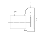
- This camera 1 is a so-called mirrorless camera of an interchangeable lens type, which is equipped with a variable magnification optical system ZL according to the present embodiment as a photographic lens 2.
- this camera 1 light from an object (subject) (not shown) is collected by a photographing lens 2, and is passed through an OLPF (optical low pass filter) (not shown) onto the imaging surface of the imaging unit 3. form an image of the subject.
- the subject image is photoelectrically converted by a photoelectric conversion element (imaging element) provided in the imaging unit 3, and an image of the subject is generated.
- This image is displayed on an EVF (Electronic view finder) 4 provided in the camera 1. This allows the photographer to observe the subject through the EVF4.
- EVF Electronic view finder
- variable magnification optical system ZL may be applied to a single-lens reflex camera that has a quick return mirror in the camera body and observes a subject using a finder optical system. Even when the camera is equipped with the camera 1, the same effects as the camera 1 described above can be achieved.
- variable magnification optical system ZL with a four-group configuration is shown, but the above configuration conditions can also be applied to other group configurations such as a five-group, a six-group, etc.
- a configuration in which a lens or lens group is added closest to the object side, or a configuration in which a lens or lens group is added closest to the image plane side may be used.
- a configuration may be considered in which a lens group whose position with respect to the image plane is fixed during zooming is added to the closest to the image plane.
- a lens group refers to a portion having at least one lens separated by an air gap that changes during zooming or focusing.
- the lens component refers to a single lens or a cemented lens in which a plurality of lenses are cemented together.
- image blur caused by camera shake can be corrected by moving the lens group or partial lens group so that it has a displacement component perpendicular to the optical axis, or rotating (swinging) it in a plane that includes the optical axis. It may also be used as a vibration isolation group. In particular, it is preferable that at least a portion of the third lens group G3 be an anti-vibration group.
- the aperture diaphragm S is arranged within or near the third lens group G3, the role may be replaced by a lens frame without providing a member as an aperture diaphragm.
- a method for manufacturing the variable magnification optical system ZL according to this embodiment will be outlined with reference to FIG. 10.
- a first lens group G1 having a negative refractive power, a second lens group G2 having a positive refractive power, a third lens group G3, and a fourth lens group G4 having a positive refractive power (Step S100).
- the distance between adjacent lens groups changes, and the first lens group G1 is fixed with respect to the image plane, and the fourth lens group G4 is arranged so as to move along the optical axis.
- Step S200 the second lens group G2 is arranged so as to move along the optical axis during focusing
- these lens groups are arranged so as to satisfy predetermined conditions (for example, the above-mentioned conditional expressions (1) and (2) and conditional expressions (3) and (4)) (step S400).
- variable magnification optical system As described above, it is possible to provide a variable magnification optical system, an optical device, and a method for manufacturing a variable magnification optical system that is suitable for video shooting, is small, lightweight, and can obtain good optical performance.
- the height of the aspherical surface in the direction perpendicular to the optical axis is y
- the distance along the optical axis from the tangent plane of the vertex of each aspherical surface to each aspherical surface at the height y is S(y)
- the radius of curvature of the reference sphere is r
- the conic constant is K
- the nth-order aspheric coefficient is An, it is expressed by the following formula (a).
- "E-n" indicates " ⁇ 10 -n ".
- the second-order aspheric coefficient A2 is 0.
- aspherical surfaces are marked with * on the right side of the surface number.
- FIG. 1 is a diagram showing the configuration of a variable magnification optical system ZL1 according to a first embodiment.
- This variable magnification optical system ZL1 includes, in order from the object side, a first lens group G1 having a negative refractive power, a second lens group G2 having a positive refractive power, and a third lens group G3 having a positive refractive power. and a fourth lens group having positive refractive power.
- the first lens group G1 includes, in order from the object side, an aspherical negative lens L11 in which the object side lens surface and the image surface side lens surface are formed in an aspherical shape, and a negative meniscus lens shape with a convex surface facing the object side;
- An aspherical negative lens L12 having an aspherical lens surface on the image side and a negative meniscus lens shape with a convex surface facing the object side, a biconcave negative lens L13, and a positive meniscus lens with a convex surface facing the object side. It is composed of L14.
- the second lens group G2 is composed of a cemented positive lens made by cementing, in order from the object side, a negative meniscus lens L21 with a convex surface facing the object side and a biconvex positive lens L22.
- the third lens group G3 includes, in order from the object side, a positive meniscus lens L31 with a convex surface facing the object side, a cemented positive lens made by cementing a negative meniscus lens L32 with a convex surface facing the object side, and a biconvex positive lens L33, and an object lens. It is composed of a negative meniscus lens L34 with a concave surface facing the side, a biconcave negative lens L35, and a positive meniscus lens L36 with a convex surface facing the object side.
- the fourth lens group G4 includes, in order from the object side, a cemented positive lens obtained by cementing a negative meniscus lens L41 with a convex surface facing the object side and a biconvex positive lens L42, a biconvex positive lens L43, and a biconcave negative lens L44.
- the distance between adjacent lens groups changes when zooming from the wide-angle end state to the telephoto end state.
- the first lens group G1 is fixed with respect to the image plane I, and the second lens group G2, the third lens group G3, and the fourth lens group G4 are fixed to the optical axis when changing the magnification. move along.
- the second lens group G2 moves toward the image plane side when focusing from infinity to a close object.
- Table 1 below lists the values of the specifications of the variable magnification optical system ZL1.
- f shown in the overall specifications is the focal length of the entire system
- Fno is the F number
- ⁇ is the half angle of view [°]
- Y is the maximum image height
- TL is the optical total length
- Bf is the back focus.
- the values represent values at infinity focus in the wide-angle end state, intermediate focal length state, and telephoto end state.
- the optical total length TL indicates the distance on the optical axis from the lens surface (first surface) closest to the object side to the image surface I.
- the back focus Bf indicates the distance on the optical axis from the lens surface (35th surface) closest to the image side to the image surface I.
- the values of the optical total length TL and the back focus Bf are air equivalent lengths.
- the first column m in the lens data indicates the order (surface number) of the lens surfaces from the object side along the direction in which the light ray travels
- the second column r indicates the radius of curvature of each lens surface.
- d is the distance on the optical axis from each optical surface to the next optical surface (interface spacing)
- the radius of curvature ⁇ indicates a plane, and the refractive index of air, 1.00000, is omitted.
- the lens group focal length indicates the surface number and focal length of the starting surface of each lens group.
- mm is generally used for the focal length f, radius of curvature r, surface spacing d, and other length units listed in all the specification values below, but the optical system Since the same optical performance can be obtained even if the size is reduced, the present invention is not limited to this. Further, the explanations of these symbols and the specifications table are the same in the following embodiments.
- the first surface, the second surface, the fourth surface, the 33rd surface, and the 35th surface are aspheric surfaces.
- Table 2 below shows aspherical surface data with respect to the surface number, ie, the values of the conic constant K and each aspherical constant A4 to A12.
- variable magnification optical system ZL1 an axial air distance D8 between the first lens group G1 and the second lens group G2, an axial air distance D11 between the second lens group G2 and the third lens group G3, and an axial air distance D11 between the second lens group G2 and the third lens group G3;
- the axial air distance D23 between the lens group G3 and the fourth lens group G4 and the back focus Bf change during zooming and focusing.
- Table 3 shows variable intervals in the wide-angle end state, intermediate focal length state, and telephoto end state when focusing on infinity and when focusing on a short-distance object.
- D0 indicates the distance from the lens surface (first surface) closest to the object side of the variable magnification optical system ZL1 to the object
- f indicates the focal length
- ⁇ indicates the photographing magnification.
- the third lens group G3 includes, in order from the object side, a positive meniscus lens L31 with a convex surface facing the object side, a cemented positive lens made by cementing a negative meniscus lens L32 with a convex surface facing the object side, and a biconvex positive lens L33; , a biconcave negative lens L34.
- variable magnification optical system ZL2 the second lens group G2 moves toward the image plane side when focusing from infinity to a close object.
- Table 4 lists the values of the specifications of the variable magnification optical system ZL2.
- the first surface, the second surface, the fourth surface, the 29th surface, and the 31st surface are aspheric surfaces.
- Table 5 shows aspherical data with respect to the surface number, that is, the values of the conic constant K and each of the aspherical constants A4 to A12.
- variable magnification optical system ZL2 the axial air distance D8 between the first lens group G1 and the second lens group G2, the axial air distance D11 between the second lens group G2 and the third lens group G3, and the axial air distance D11 between the second lens group G2 and the third lens group G3,
- the axial air distance D19 between the lens group G3 and the fourth lens group G4 and the back focus Bf change during zooming and focusing.
- Table 6 shows variable intervals in the wide-angle end state, intermediate focal length state, and telephoto end state when focusing on infinity and when focusing on a short distance object.
- FIG. 4 shows a spherical aberration diagram, an astigmatism diagram, a distortion aberration diagram, a magnification chromatic aberration diagram, and a coma aberration diagram when focusing on infinity in the wide-angle end state and telephoto end state of this variable magnification optical system ZL2. From these aberration diagrams, it can be seen that the variable magnification optical system ZL2 has various aberrations well corrected and has excellent imaging performance.
- FIG. 5 is a diagram showing the configuration of a variable magnification optical system ZL3 according to the third embodiment.
- This variable magnification optical system ZL3 includes, in order from the object side, a first lens group G1 having a negative refractive power, a second lens group G2 having a positive refractive power, and a third lens group G3 having a negative refractive power. and a fourth lens group having positive refractive power.
- the first lens group G1 includes, in order from the object side, an aspherical negative lens L11 having an aspherical lens surface on the image side and a negative meniscus lens shape with a convex surface facing the object side, a biconcave negative lens L12,
- the image plane side lens surface is formed into an aspherical shape, and is composed of an aspherical positive lens L13 having a positive meniscus lens shape with a convex surface facing the object side.
- the second lens group G2 includes, in order from the object side, an aspherical negative lens L21 having an aspherical lens surface on the object side and a negative meniscus lens shape with a convex surface facing the object side, and a biconvex positive lens L22. It consists of a cemented positive lens.
- the third lens group G3 is composed of, in order from the object side, a negative meniscus lens L31 with a convex surface facing the object side, a negative meniscus lens L32 with a concave surface facing the object side, and a biconvex positive lens L33.
- the fourth lens group G4 includes, in order from the object side, a cemented positive lens consisting of a double-convex positive lens L41 and a negative meniscus lens L42 with a concave surface facing the object side, a double-convex positive lens L43, and a double-convex positive lens L43 with a concave surface facing the object side.
- a cemented negative lens made by cementing a positive meniscus lens L44 and a biconcave negative lens L45, and a negative meniscus lens in which the object side lens surface and the image surface side lens surface are formed into an aspherical shape, and the convex surface faces the object side. It is composed of an aspherical negative lens L46.
- the distance between adjacent lens groups changes when zooming from the wide-angle end state to the telephoto end state.
- the first lens group G1 is fixed with respect to the image plane I, and the second lens group G2, third lens group G3, and fourth lens group G4 are fixed to the optical axis. move along.
- variable magnification optical system ZL3 when focusing from infinity to a close object, the second lens group G2 moves toward the image plane side, and the third lens group G3 moves toward the object side.
- the aperture stop S is arranged between the negative meniscus lens L31 and the negative meniscus lens L32 of the third lens group G3, and the third lens It moves along the optical axis together with group G3.
- Table 7 below lists the values of the specifications of the variable magnification optical system ZL3.
- the second surface, the sixth surface, the seventh surface, the 25th surface, and the 26th surface are aspheric surfaces.
- Table 8 shows aspherical surface data with respect to the surface number, that is, the values of the conic constant K and each of the aspherical constants A4 to A12.
- variable magnification optical system ZL3 the axial air distance D6 between the first lens group G1 and the second lens group G2, the axial air distance D9 between the second lens group G2 and the third lens group G3, and the axial air distance D9 between the second lens group G2 and the third lens group G3,
- the axial air distance D16 between the lens group G3 and the fourth lens group G4 and the back focus Bf change during zooming and focusing.
- Table 9 shows variable intervals in the wide-angle end state, intermediate focal length state, and telephoto end state when focusing on infinity and when focusing on a short-distance object.
- FIG. 7 is a diagram showing the configuration of a variable magnification optical system ZL4 according to the fourth embodiment.
- This variable magnification optical system ZL4 includes, in order from the object side, a first lens group G1 having a negative refractive power, a second lens group G2 having a positive refractive power, and a third lens group G3 having a negative refractive power. and a fourth lens group having positive refractive power.
- the fourth lens group G4 includes, in order from the object side, a cemented positive lens consisting of a double-convex positive lens L41 and a negative meniscus lens L42 with a concave surface facing the object side, a double-convex positive lens L43, a double-convex positive lens L44, and a double-convex positive lens L44. It is composed of a cemented negative lens that is cemented with a concave negative lens L45, and an aspherical negative lens L46 whose object-side lens surface and image-side lens surface are formed into an aspherical shape and which is a biconcave negative lens shape. .
- the aperture stop S is arranged on the object side of the third lens group G3, and moves along the optical axis together with the third lens group G3 during zooming and focusing.
- FIG. 8 shows a spherical aberration diagram, an astigmatism diagram, a distortion aberration diagram, a magnification chromatic aberration diagram, and a coma aberration diagram when focusing on infinity in the wide-angle end state and telephoto end state of this variable magnification optical system ZL4. From these aberration diagrams, it can be seen that the variable magnification optical system ZL4 has various aberrations well corrected and has excellent imaging performance.
Landscapes
- Physics & Mathematics (AREA)
- General Physics & Mathematics (AREA)
- Optics & Photonics (AREA)
- Nonlinear Science (AREA)
- Lenses (AREA)
Priority Applications (3)
| Application Number | Priority Date | Filing Date | Title |
|---|---|---|---|
| JP2024509953A JP7821409B2 (ja) | 2022-03-24 | 2023-03-07 | 変倍光学系及び光学機器 |
| US18/849,524 US20250199275A1 (en) | 2022-03-24 | 2023-03-07 | Zoom optical system, optical apparatus, and method for manufacturing zoom optical system |
| CN202380027500.1A CN118805114A (zh) | 2022-03-24 | 2023-03-07 | 变倍光学系统、光学设备及变倍光学系统的制造方法 |
Applications Claiming Priority (2)
| Application Number | Priority Date | Filing Date | Title |
|---|---|---|---|
| JP2022047890 | 2022-03-24 | ||
| JP2022-047890 | 2022-03-24 |
Publications (1)
| Publication Number | Publication Date |
|---|---|
| WO2023181903A1 true WO2023181903A1 (ja) | 2023-09-28 |
Family
ID=88100717
Family Applications (1)
| Application Number | Title | Priority Date | Filing Date |
|---|---|---|---|
| PCT/JP2023/008475 Ceased WO2023181903A1 (ja) | 2022-03-24 | 2023-03-07 | 変倍光学系、光学機器及び変倍光学系の製造方法 |
Country Status (4)
| Country | Link |
|---|---|
| US (1) | US20250199275A1 (https=) |
| JP (1) | JP7821409B2 (https=) |
| CN (1) | CN118805114A (https=) |
| WO (1) | WO2023181903A1 (https=) |
Cited By (2)
| Publication number | Priority date | Publication date | Assignee | Title |
|---|---|---|---|---|
| JP2023145843A (ja) * | 2022-03-29 | 2023-10-12 | 株式会社シグマ | 大口径比超広角ズームレンズ及びこれを備える撮像装置 |
| WO2026053931A1 (ja) * | 2024-09-03 | 2026-03-12 | キヤノン株式会社 | ズームレンズ及び撮像装置 |
Families Citing this family (1)
| Publication number | Priority date | Publication date | Assignee | Title |
|---|---|---|---|---|
| JP2024076793A (ja) * | 2022-11-25 | 2024-06-06 | キヤノン株式会社 | ズームレンズ、およびそれを有する撮像装置、撮像システム |
Citations (5)
| Publication number | Priority date | Publication date | Assignee | Title |
|---|---|---|---|---|
| JPH09152552A (ja) * | 1995-11-28 | 1997-06-10 | Nikon Corp | ズームレンズ |
| JPH1048521A (ja) * | 1996-08-08 | 1998-02-20 | Konica Corp | ズームレンズ |
| JP2004069808A (ja) * | 2002-08-02 | 2004-03-04 | Olympus Corp | ズームレンズ及びそれを用いた電子撮像装置 |
| JP2007183664A (ja) * | 2001-05-14 | 2007-07-19 | Olympus Corp | 電子撮像装置 |
| JP2009162809A (ja) * | 2007-12-28 | 2009-07-23 | Canon Inc | 光学系及びそれを有する光学機器 |
Family Cites Families (6)
| Publication number | Priority date | Publication date | Assignee | Title |
|---|---|---|---|---|
| JP4573945B2 (ja) * | 2000-05-10 | 2010-11-04 | キヤノン株式会社 | ズームレンズ及びそれを用いた光学機器 |
| JP2004037925A (ja) * | 2002-07-04 | 2004-02-05 | Minolta Co Ltd | 撮像装置 |
| JP5560624B2 (ja) * | 2009-08-31 | 2014-07-30 | カシオ計算機株式会社 | ズームレンズ及び投射型表示装置 |
| JP6198172B2 (ja) * | 2012-12-25 | 2017-09-20 | 株式会社リコー | 投射用ズームレンズ、投射光学系および画像表示装置 |
| JP7506498B2 (ja) * | 2020-03-17 | 2024-06-26 | 株式会社タムロン | ズームレンズおよび撮像装置 |
| JP7551444B2 (ja) * | 2020-10-15 | 2024-09-17 | キヤノン株式会社 | ズームレンズおよび撮像装置 |
-
2023
- 2023-03-07 WO PCT/JP2023/008475 patent/WO2023181903A1/ja not_active Ceased
- 2023-03-07 JP JP2024509953A patent/JP7821409B2/ja active Active
- 2023-03-07 US US18/849,524 patent/US20250199275A1/en active Pending
- 2023-03-07 CN CN202380027500.1A patent/CN118805114A/zh active Pending
Patent Citations (5)
| Publication number | Priority date | Publication date | Assignee | Title |
|---|---|---|---|---|
| JPH09152552A (ja) * | 1995-11-28 | 1997-06-10 | Nikon Corp | ズームレンズ |
| JPH1048521A (ja) * | 1996-08-08 | 1998-02-20 | Konica Corp | ズームレンズ |
| JP2007183664A (ja) * | 2001-05-14 | 2007-07-19 | Olympus Corp | 電子撮像装置 |
| JP2004069808A (ja) * | 2002-08-02 | 2004-03-04 | Olympus Corp | ズームレンズ及びそれを用いた電子撮像装置 |
| JP2009162809A (ja) * | 2007-12-28 | 2009-07-23 | Canon Inc | 光学系及びそれを有する光学機器 |
Cited By (3)
| Publication number | Priority date | Publication date | Assignee | Title |
|---|---|---|---|---|
| JP2023145843A (ja) * | 2022-03-29 | 2023-10-12 | 株式会社シグマ | 大口径比超広角ズームレンズ及びこれを備える撮像装置 |
| JP7819912B2 (ja) | 2022-03-29 | 2026-02-25 | 株式会社シグマ | 大口径比超広角ズームレンズ及びこれを備える撮像装置 |
| WO2026053931A1 (ja) * | 2024-09-03 | 2026-03-12 | キヤノン株式会社 | ズームレンズ及び撮像装置 |
Also Published As
| Publication number | Publication date |
|---|---|
| CN118805114A (zh) | 2024-10-18 |
| JPWO2023181903A1 (https=) | 2023-09-28 |
| US20250199275A1 (en) | 2025-06-19 |
| JP7821409B2 (ja) | 2026-02-27 |
Similar Documents
| Publication | Publication Date | Title |
|---|---|---|
| WO2010018727A1 (ja) | ズームレンズ、このズームレンズを備えた光学機器、及び、ズームレンズの製造方法 | |
| JP5557092B2 (ja) | ズームレンズ、光学機器、およびズームレンズの製造方法 | |
| JP7821409B2 (ja) | 変倍光学系及び光学機器 | |
| JP5648894B2 (ja) | ズームレンズ、光学機器及びズームレンズの製造方法 | |
| JP5344291B2 (ja) | ズームレンズ、光学機器及びズームレンズの製造方法 | |
| WO2015016112A1 (ja) | 変倍光学系、光学装置及び変倍光学系の製造方法 | |
| JP5594607B2 (ja) | ズームレンズおよび撮像装置 | |
| WO2015162883A1 (ja) | 変倍光学系、光学機器及び変倍光学系の製造方法 | |
| JP2018101156A (ja) | ズームレンズおよび光学機器 | |
| JP2017156428A (ja) | 変倍光学系、光学機器及び変倍光学系の製造方法 | |
| JP6507471B2 (ja) | 光学系、及び光学装置 | |
| JP2017156426A (ja) | 変倍光学系、光学機器及び変倍光学系の製造方法 | |
| JP5668409B2 (ja) | ズームレンズおよび光学機器 | |
| JP5713227B2 (ja) | ズームレンズ、光学機器及びズームレンズの製造方法 | |
| JP6467804B2 (ja) | ズームレンズ、及び光学機器 | |
| CN104272163A (zh) | 变焦光学系统、光学设备和用于制造变焦光学系统的方法 | |
| JP7272433B2 (ja) | 変倍光学系および光学機器 | |
| JP5906759B2 (ja) | ズームレンズ、光学機器及びズームレンズの製造方法 | |
| JP7259956B2 (ja) | 変倍光学系および光学機器 | |
| JP6265022B2 (ja) | 変倍光学系、光学機器及び変倍光学系の製造方法 | |
| JP6446821B2 (ja) | 変倍光学系及び光学機器 | |
| JP7211440B2 (ja) | 変倍光学系および光学機器 | |
| JP5594606B2 (ja) | ズームレンズおよび撮像装置 | |
| JP6627915B2 (ja) | 変倍光学系及び光学機器 | |
| JPWO2016194811A1 (ja) | 変倍光学系、光学機器及び変倍光学系の製造方法 |
Legal Events
| Date | Code | Title | Description |
|---|---|---|---|
| 121 | Ep: the epo has been informed by wipo that ep was designated in this application |
Ref document number: 23774502 Country of ref document: EP Kind code of ref document: A1 |
|
| ENP | Entry into the national phase |
Ref document number: 2024509953 Country of ref document: JP Kind code of ref document: A |
|
| WWE | Wipo information: entry into national phase |
Ref document number: 202380027500.1 Country of ref document: CN |
|
| WWE | Wipo information: entry into national phase |
Ref document number: 18849524 Country of ref document: US |
|
| NENP | Non-entry into the national phase |
Ref country code: DE |
|
| 122 | Ep: pct application non-entry in european phase |
Ref document number: 23774502 Country of ref document: EP Kind code of ref document: A1 |
|
| WWP | Wipo information: published in national office |
Ref document number: 18849524 Country of ref document: US |